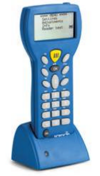
Nordic ID RF650 Wireless data collection terminal User Manual RF650 Manual Version 1 1 ENG
Nordic ID Oy Wireless data collection terminal RF650 Manual Version 1 1 ENG
User manual
Nordic ID RF650 User’s Manual
Version 1.0
June 1st, 2004
Nordic ID Copyright © 2004
All rights reserved.
Nordic ID assumes no responsibility for any errors, which may appear in this
manual. Furthermore, Nordic ID reserves the right to alter the hardware,
software, and/or specifications detailed herein at any time without notice, and do
not make any commitment to update the information contained herein.
Updates to this manual may be checked from the Nordic ID Internet pages
(http://www.nordicid.com).
Nordic ID products are not authorized for use as critical components in life
support devices or systems.
The WRAP is a registered trademark of Bluegiga Technologies.
The Bluetooth trademark is owned by the Bluetooth SIG Inc., USA, and is
licensed to Nordic ID.
All other trademarks listed herein belong to their respective owners.
3
Table of Contents
1 EC Declaration of Conformity.......................................................................................5
2 General information.......................................................................................................6
2.1 The purpose of the use of the Nordic ID RF650................................................6
2.2 Copyright and Disclaimer ..................................................................................6
2.3 Version information...........................................................................................6
2.4 User safety information......................................................................................6
2.5 FCC related information....................................................................................8
2.5.1 FCC Compliance Statement............................................................................8
2.5.2 FCC Class B Part 15 and WRAP...................................................................9
2.6 IC related information........................................................................................9
2.7 Warranty.............................................................................................................9
2.8 Restrictions on use ...........................................................................................10
3 About this manual........................................................................................................11
3.1 Checking for latest version of this manual ......................................................11
4 Introduction..................................................................................................................12
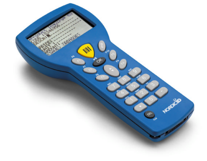
4.1 System components.........................................................................................12
4.1.1 Versions of RF650 ........................................................................................12
4.1.2 Product identification label and serial number .............................................12
4.2 Basic system operation.....................................................................................13
4.3 General operation of the Hand Terminal.........................................................13
4.4 Communication between the WRAP and the Host Computer.........................14
4.4.1 Transaction Start...........................................................................................14
4.4.2 The WRAP receives a message from the Hand Terminal ............................14
4.4.3 The HOST application receives the frame from the WRAP.........................14
4.4.4 The HOST application handles the frame.....................................................15
4.4.5 HOST sends an answer to the Hand Terminal via WRAP ...........................15
4.4.6 The WRAP sends the frame to the Hand Terminal ......................................15
4.4.7 The Hand Terminal receives a frame from the WRAP.................................15
4.4.8 Transaction End ............................................................................................15
5 Getting Started.............................................................................................................16
5.1 Unpacking the unit...........................................................................................16
5.2 Charging the batteries ......................................................................................16
5.3 Activating the Hand Terminal..........................................................................16
5.4 Resetting the Hand Terminal...........................................................................17
5.5 Symbols of the display.....................................................................................17
5.6 Sound ...............................................................................................................17
5.7 Keyboard..........................................................................................................18
5.8 F-Keys ..............................................................................................................19
5.9 Character map..................................................................................................19
5.10 Initial display....................................................................................................19
5.11 Setting the PIN-code ........................................................................................21
5.12 Searching for the Base Stations .......................................................................21
5.13 Input fields .......................................................................................................22
5.14 Locked fields....................................................................................................23
4
5.15 Filling fields using the laser scanner................................................................23
5.16 Writing text in a field .......................................................................................23
5.17 Writing letters ..................................................................................................23
5.18 Removing letters ..............................................................................................23
5.19 Moving between fields.....................................................................................24
5.20 Menu................................................................................................................24
5.21 Main user settings ............................................................................................24
5.22 Adjustments .....................................................................................................24
5.23 Info...................................................................................................................24
5.24 Versions of the RF650 .....................................................................................24
6 Desk Top Charger ........................................................................................................26
6.1 General information.........................................................................................26
6.2 Safety information............................................................................................26
6.3 Desk Top Charger system components............................................................26
6.4 Connectors .......................................................................................................27
6.5 Charging indicator............................................................................................27
6.6 Battery types ....................................................................................................27
6.7 Charging the batteries ......................................................................................28
6.7.1 Audio signals and the Charging Indicator LED............................................29
7 Installation and use.......................................................................................................30
7.1 Basic installation of the RF650 Hand Terminal ..............................................30
7.2 Installation of the WRAP.................................................................................30
8 Appendix......................................................................................................................31
8.1 Technical specifications of the RF650 Hand Terminal ...................................32
8.2 Technical specifications of the Desk Top Charger..........................................33
8.3 Minimum system requirements for software installation................................34
8.4 Useful links ......................................................................................................34
8.5 Trademarks.......................................................................................................35
8.6 Programming the RF650 laser scanner module ...............................................35
8.7 Default factory settings of the Laser engine ....................................................37
8.8 Status messages of RF650 Hand Terminal......................................................39
8.9 “Out of Range!” ...............................................................................................39
8.10 “Searching” ......................................................................................................39
8.11 “Connecting…”................................................................................................39
8.12 “Connected! .....................................................................................................40
8.13 “Processing data!..............................................................................................40
8.14 “No answer from Host”....................................................................................40
8.15 “Battery low” ...................................................................................................40
8.16 Frequently asked questions ..............................................................................41
8.17 Service and Support contacts ...........................................................................41
8.18 Sending the unit to service (Service Report Form)..........................................42
8.19 Contact information.........................................................................................45

5
1 EC Declaration of Conformity
Nordic ID hereby declares, that Nordic ID RF650
wireless data collection systems
have been tested according to the standards EN 300 328-2 and EN 301 489-17.
The equipment conforms to the essential requirements of the
Directive
1999/5/EC.
Salo 1.6.2004,
Jorma Lalla, Managing Director
Nordic ID Oy
6
2 General information
2.1 The purpose of the use of the Nordic ID RF650
The Nordic ID RF650 Hand Terminal (RF650) and Wireless Remote Access
Platform (WRAP, Access Server) are designed to be used as a part of a
Nordic ID Wireless Data Collection and Communication System in accordance
with this User’s Manual. Any inappropriate use of the equipment for any other
purpose is strictly prohibited.
Please note that national and/or local regulations and/or laws may limit or
regulate the use of all or any part of the RF650 Hand Terminal, WRAP or the
system.
2.2 Copyright and Disclaimer
All rights to this manual are owned solely by Nordic ID Oy (referred to in this
user's guide also as Nordic ID). All rights reserved. The copying of this manual
without the written permission from Nordic ID by any means is strictly prohibited
excluding cases where the copying is related to end-customer or system
integrator use.
In order to enhance the functionality of its products, Nordic ID reserves the right
to change the technical specifications or functions of its products within the scope
of any existing applicable standards or regulations.
Nordic ID assumes no responsibility if any of its products is used in unlawful
ways.
2.3 Version information
The reader of this manual is advised to check for possible newer editions of this
User’s Manual. For more information on latest version, please visit our Internet-
pages at http://www.nordicid.com.
2.4 User safety information
Nordic ID products have not been designed, intended nor inspected to be used in
any life support related device or system related function nor as a part of any
other critical system and are granted no functional warranty if used in any of the
applications mentioned above.
7
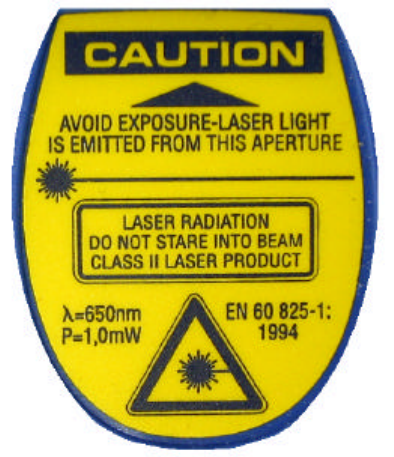
Specific versions of RF650 Hand Terminal contain a Laser Scanner Module, an
RFID reader/writer or both. The laser of the Laser Scanner Module is a Class II
Laser, which are deemed safe for the use they are applied for in this product.
User’s should never look directly into the laser and must refrain from directing the
laser at the eyes of other persons or animals. It should also be noted, that some
electronic sensors may be effected by laser light. Please note that shiny surfaces
may reflect the laser beam into unexpected directions.
The RFID reader/writer used in specific versions of the RF650 emit RF-energy
and may thus cause disturbances to electronic equipment when used
inappropriately.
The radio parts of the RF650 Hand Terminal and the WRAP emit radio frequency
energy. Although the radio frequency energy levels normally emitted from these
products comply with applicable regulations, users with pacemakers are warned
of possible interference to pacemaker functions. Customers of systems using the
RF650 Hand Terminal and/or WRAP are advised to educate the end-users of
possible danger to pacemakers in order to avoid personal injury.
The RF650 Hand Terminal is supplied with a Laser light warning label located in
the back of the unit. See below.
ENGLISH SUOMI
LASER LIGHT VAARA LASERSATEILYÄ
DO NOT STARE INTO BEAM ÄLÄ TUIJOTA SÄTEESEEN
CLASS 2 LASER LUOKKA 2 LASER
DEUTCH SVENSKA
8
LASERSTRAHLEN VARNING LASERSTÅLNING
NICHT DIREKT IN DEN LASERSTRAHL SCHAUEN STIRRA EJ IN I STRÅLEN
LASERPRODUKT DER KLASSE 2 KLASS 2 LASER
DANSK ITALIANO
LASERLYF LUCE LASER
SE IKKE IND I STRÅLEN NON FISSARE IL RAGGIOPRODOTTO
KLASSE 2 LASER AL LASER DI CLASSE 2
FRANÇAIS ESPAÑOL
LUMIERE LASER LUZ LASER
NE PAS REGARDER LE RAYON FIXEMENT NO MIRE FIJAMENTE EL HAZ
PRODUIT LASER DE CLASSE 2 PRODUCTO LASER DE LA CLASE 2
NEDERLANDS NORSK
LASERLICHT NIET IN STRAAL STAREN LASERLYS IKKE STIRR INN I LYSSTRÅLEN
KLASSE-2 LASER LASER, KLASSE 2
PORTUGUÊS
LUZ DE LASER NÃO FIXAR O RAIO LUMINOSO
PRODUTO LASER DA CLASSE 2
Please check the WRAP User’s Manual for specific instructions relating to the
installation and placement of the WRAP unit.
2.5 FCC related information
The RF650 has been tested according to FCC regulations.
2.5.1 FCC Compliance Statement
This equipment has been tested and found to comply with the limits for a Class B
digital device, pursuant to Part 15 of FCC Rules.
These limits are designed to provide reasonable protection against harmful
interference in a residential installation.
This equipment generates, uses and can radiate radio frequency energy and, if not
installed and used in accordance with the instructions, may cause harmful interference
to radio communications. However, there is no guarantee that interference will not
occur in a particular installation. If this equipment does cause harmful interference to
radio or television reception, which can be determined by turning the equipment off
and on, the user is encouraged to try to correct the interference by one or more of the
following measures:
• Reorient or relocate the receiving antenna.
• Increase the separation between the equipment and receiver.
9
• Connect the equipment into an outlet on a circuit different from that to which the
receiver in connected.
• Consult the dealer or an experienced radio/TV technician for help.
FCC NOTICE
1. Use only the power cord and connector cables supplied by Nordic ID
to connect the equipment.
2. Use only shielded cables to connect I/O devices to this equipment.
3. Changes or modifications not expressly approved by the party
responsible for compliance could void the user’s authority to operate
the equipment.
2.5.2 FCC Class B Part 15 and WRAP
The radiated output power of the WRAP is far below the FCC radio frequency
exposure limits. Nevertheless, the WRAP should be used in such a manner that
the potential for human contact during normal operation is minimized.
2.6 IC related information
This device complies with Part 15 of the FCC Rules and with RSS-210 of
Industry Canada.
Operation is subject to the following two conditions:
1. This device may not cause harmful interference, and
2. This device must accept any interference received, including interference
that may cause undesired operation.
2.7 Warranty
Nordic ID grants warranty to its products according to the Nordic ID General
Sales Conditions.
Warranty will be void, should the Nordic ID products be used in ways in
contradiction with the instructions laid out in this User’s Manual, or should the
products’ housing be opened or tampered with.
10
The products mentioned in this User's Manual are to be used only according to
the instructions described in this manual. Faultless and safe operation of the
products can be guaranteed only if the transport, storage, operation and handling
of the devices are appropriate. This also applies to the maintenance of the
products.
To prevent damage to products please follow normal ESD related procedures
when handling the products. Switch off power from devices (remove
rechargeable batteries from Hand Terminal or remove the Hand Terminal from
the Desk Top Charger and disconnect the power input from the WRAP) when
connecting or disconnecting serial cable connections.
2.8 Restrictions on use
Nordic ID products have been designed to operate on frequency ranges
allocated to the use in questions by local and international laws, regulations and
standards. The users of the products are responsible for taking care that all local
and international regulations regarding EMI and electrical safety are followed
regarding the installation and operation of the products by themselves and/or as
part of a system.
Any modifications to the internal parts or the antenna, hardware or software
related, other than described by the original manufacturer of the product in
question, are strictly prohibited. Nordic ID will not bear any responsibility for use
of its products, which have been tampered with.
11
3 About this manual
This User’s Manual contains information about the Nordic ID RF650 Hand
Terminal and the RF650 Access Server (WRAP).
Chapter ###
Chapter 3 (About this manual) includes information about this manual and
instructions on how to download the latest version of the manual via Internet.
Chapter 4 (Introduction) contains an overview of the RF650 Hand Terminal and
the RF650 Access Server. A default basic solution is described and the relation
between the RF650 system and the host application is also explained.
Chapter 5 (Getting Started) contains instructions on how to start using your RF
650 Hand Terminal and the RF650 Access Server.
Chapter 6 (Desk Top Charger) contains instructions on how to start using your
Desktop Charger.
Chapter 7 (Installation and use) explains the basic installation of the Hand
Terminal and WRAP
Chapter 8 (Appendix) Contains useful additional information and contact
addresses.
3.1 Checking for latest version of this manual
You can check the latest version of this manual at our Internet-pages at
http://www.nordicid.com.
The version and date of the manual are indicated on the front page of the
manual. Please note that some functions and characteristics described in any
version of this manual might not reflect the functions of the Hand Terminal or the
WRAP, if they have firmware relating to earlier versions.
Information concerning the updating of the firmware of the RF650 Hand Terminal
and the WRAP are available at the Nordic ID Technical Support web pages at
http://www.nordicid.com.
12
4 Introduction
This chapter contains an overview of the Nordic ID RF650 Wireless Data
Collection System, which consists of one or more RF650 Hand Terminal and one
or more RF650 Wireless Remote Access Platform (WRAP). The principle of
operation and the relation between the RF650 Hand Terminal and WRAP and the
Application Software running in the Host Computer are also shortly explained.
4.1 System components
The Nordic ID RF650 Wireless Data Collection System consists of three principal
components:
• Nordic ID RF650 Hand Terminal(s)
• Wireless Remote Access Platform(s) (WRAP)
• The Application Software, which runs on the Host Computer. Application
Software and Host Computer are not delivered by Nordic ID.
4.1.1 Versions of RF650
The RF650 is available in three different production versions:
• RF650 with Laser Scanner for bar codes
• RF650 with RFID for RFID tags
• RF650 with Laser Scanner and RFID both of the above
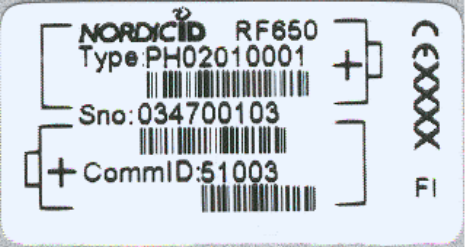
4.1.2 Product identification label and serial number
A product ID label is located inside the casing at the bottom of the rechargeable
battery holder. The label may be read by opening the battery cover and by
removing the batteries. Serial number can be used for tracing product
information and service history.
13
4.2 Basic system operation
The Hand Terminals communicate with the Host computer via the Wireless
Remote Access Platform(s) (WRAP). The system can include one or more Hand
Terminals and one or more WRAPs. A WRAP can be interfaced directly to the
Host Computer using an RS232 interface, or indirectly via different networks
(WLAN, GPRS etc.) with network cable or with third party adapters. The Hand
Terminals can send/receive data to/from the Host Computer.
The integrity of data transfers between the systems components are always
checked using the check sum method. Data transfers are always acknowledged,
which assures that possible data loss due to e.g. radio interference is always
detected. Detection of data loss generates a resending process.
The maximum number of Hand Terminals per WRAP depends on the make and
model of the WRAP. The number of WRAPs is limited by the Bluetooth standard,
but may also depend on the make and model of WRAPs.
4.3 General operation of the Hand Terminal
Nordic ID RF650 is a thin client terminal. It is used as a user interface to a
Software application in Host Computer. The terminal cannot be utilized without
an application and a host computer.
The initial screen of the Hand Terminal displays a prompt (user configurable
header text) and an input field. This field can be filled with data from the
keyboard or by activating the Laser Scanner for a reading of a bar code or by
activating the RFID reader for a reading of an RFID tag.
Any text sent by the Host Computer will clear the screen and show the text
received from the Host Computer. Any user input (from the keyboard or the Laser
Scanner) would clear the text received from the Host Computer and the initial
screen will be displayed again.
The user starts a transaction by using the Hand Terminal keyboard to make an
entry, or by scanning a barcode or an RFID tag. The Hand Terminal then sends
this data to the Host Computer (via the WRAP and a possible network) and waits
for a message from the Host. If the Hand Terminal does not receive a correct
message within the specified time-out period, it will generate a “HOST NOT
ANSWER” status message on the screen.
14
4.4 Communication between the WRAP and the Host Computer
4.4.1 Transaction Start
The user of the Hand Terminal sends data to the HOST. The user has
executed an action, e.g. pressed the OK-button or scanned a bar code.
The Hand Terminal user initiates sending by:
• Pressing the OK-button when the display shows the start frame
• Pressing a function key (F1-F10), which has been specified to
send a character string
• From input field which has been specified to send by pressing OK
or after reading with a laser scanner.
Sending sequence of the Hand Terminal consists of:
1. Counting and adding to the frame to be sent the CRC checksum
2. Generating a “processing data” text to the Hand Terminal’s
screen
3. Sending of the frame
4. Waiting for an answer from the HOST for a time defined by the
user as the limit for the timeout.
NOTE: It is not possible to execute any functions while waiting for the ack from
the Host system.
4.4.2 The WRAP receives a message from the Hand Terminal
Upon receiving a message from the Hand Terminal, the WRAP will:
• Verify the integrity of the data frame using the CRC method.
If the frame is flawless, it will be forwarded to the RS232 serial interface and to
the network connection.
4.4.3 The HOST application receives the frame from the WRAP
The HOST application will receive the frame according to the RF650 HOST
protocol.
The HOST application has to execute the following checks before the frame
data can be given to business logic handling:
15
• CRC value is received with the frame. It is needed for checking the cable
connection between the WRAP and the HOST. This checking is necessary only
when the RS232 cable connection is > 25 m.
• The processing of two similar messages must be avoided in the HOST
application. Depending on CRC, MN (message number) and ID (own IP
number) values can be checked to detect if the frame is the same as the one
already in process.
4.4.4 The HOST application handles the frame
HOST application handles the frame data. The HOST application must have
the commID number of the Hand Terminal during the whole data processing
time so that application is able to answer to the correct Hand Terminal.
4.4.5 HOST sends an answer to the Hand Terminal via WRAP
When the HOST application has processed the Hand Terminal’s frame it sends
an answer to the Hand Terminal of the frame according to the command HOST
RF650 protocol.
It is recommended that the HOST application is programmed to keep in
memory the last frame sent for each Hand Terminal, so that the host can
answer any retransmission requests of Hand Terminals as quickly as possible.
4.4.6 The WRAP sends the frame to the Hand Terminal
When the WRAP has received the frame from the HOST it does the following:
• The CRC is checked
• A frame is sent to the Hand Terminal.
4.4.7 The Hand Terminal receives a frame from the WRAP
When the Hand Terminal has received the frame from the WRAP it does the
following:
• The CRC is checked
• Frame commands are executed
• A short beep is generated.
4.4.8 Transaction End
The Hand Terminal and the WRAP are ready for a new transaction.
1
6
5 Getting Started
5.1 Unpacking the unit
Nordic ID products are packaged in carton boxes (boxes include the Nordic ID
logo and colors). The standard package includes typically the RF650 Hand
Terminal, rechargeable batteries (2 pcs), Desk Top Charger, the power supply
for the charger with power cord and the connector cable for the Hand Terminal.
The WRAP is packaged separately. The package contains the WRAP and the
power supply together with the power cord.
Please check the equipment upon arrival. Check that the boxes are intact and
contain no visibly damaged parts. If you note any parts, which seem damaged,
please contact your local Nordic ID Sales Representative or Nordic ID
Technical Support.
5.2 Charging the batteries
Before using the RF650 Hand Terminal you must place the rechargeable
batteries into the Hand Terminal battery compartment. Open the battery case
cover in the back of the Hand Terminal and place the batteries in the battery
holder. Place the batteries according to the polarity indicators in the holder.
When charging the batteries from fully discharged status, the charging process
takes approximately 2,5 hours.
Charging alkaline batteries in the charger may damage the charger as well as
the batteries.
5.3 Activating the Hand Terminal
The Hand Terminal does not have a separate power switch (ON/OFF). With
adequately charged batteries, the Hand Terminal is always ready to function by
pressing any key. The Hand Terminal will resume its standby state 90 seconds
after the last user function (key press).
The Start up screen asks for a 4 digit PIN-code. The default factory setting of
the PIN-code is 1234.

17
5.4 Resetting the Hand Terminal
The Hand Terminal can be reset by pressing SHIFT+DEL (press SHIFT and
while keeping the SHIFT-key down press DEL). The Hand Terminal will
automatically reset when installing new batteries.
During reset, the Hand Terminal will beep twice.
5.5 Symbols of the display
Special symbols will be shown on the right side of the display depending on the
function:
SHIFTLOCK. This function will be ON or OFF by pressing the
shift key.
TRANSACTION. This sign shows up, when the Hand
Terminal is communicating with the HOST.
EXTERNAL READER. This sign shows up, when the external
reader is activated. (SHIFTLOCK + laser button).
5.6 Sound
Resetting Hand Terminal 2 beeps
Transaction failure 5 beeps
Bad battery condition 1 beeps with “low battery” text
Reception of message At least 1 beep, can be more.
Successful reading of laser scanner 1 beep
Opening keylock 1 long beep
Wrong password 3 fast beeps

18
5.7 Keyboard
Key function table:
Key
Function with shift
key (shift + key
pressed at the same
time ).
Function with
SHIFTLOCK Normal function
Laser *** External reader will be
activated if allowed by
the current input field.
In scanner mode: The Laser
reader will be activated if allowed
by the current input field.
In light mode: The bright led will
be on as long as key is down.
F1 *** F6 F1
F2 *** F7 F2
F3 *** F8 F3
F4 *** F9 F4
F5 *** F10 F5
OK Keylock ON / OFF Normal function
The cursor will be moved to the
next field and/or the content of the
field sent to the HOST if allowed
by the current field definition
Arrow up
Scrolls display
upward Moves the cursor step
by step to the left. Displays the previous field of the
form.
Arrow
down Scrolls display
downward Moves the cursor step
by step to the right. Displays the next field of the form.
Shift *** SHIFTLOCK OFF SHIFTLOCK ON
7 *** ABC abc 7
8 *** DEF def 8
9 *** GHI ghi 9
4 *** JKL jkl 4
5 *** MNO mno 5
6 *** PQR pqr 6
1 Receiver mode
on/off STU stu 1
2 *** VWX vwx 2
3 *** YZÅÄÖ yzåäö 3
. Scanner / Light ↵ : ; ! ? " # & @ | .
0 MENU < > [ ] Ü { } ( ) ü 0
- Backlight (option) Spc + * / % = $ £ ± ½ -
DEL Reset Normal function Removes a character from the
current field.
19
5.8 F-Keys
The F-Keys F1 - F10 can be programmed to include recurring strings.
The F-Keys function in two different ways:
1. By pressing an F-Key, a string is printed in the current field. If the
length of the string exceeds the length of the field, the excess
characters will be omitted. If the field already contains a text, this will
be replaced by the new text.
2. By pressing an F-key, the string of characters is sent to the HOST.
5.9 Character map
The picture below contains the default character map of the RF650 Hand
Terminal.
Nordic ID is able to add customer specific or language specific characters to
the character map or provide tools for character map modification. Nordic ID
may charge an extra fee for the character map modification or the tools.
5.10 Initial display
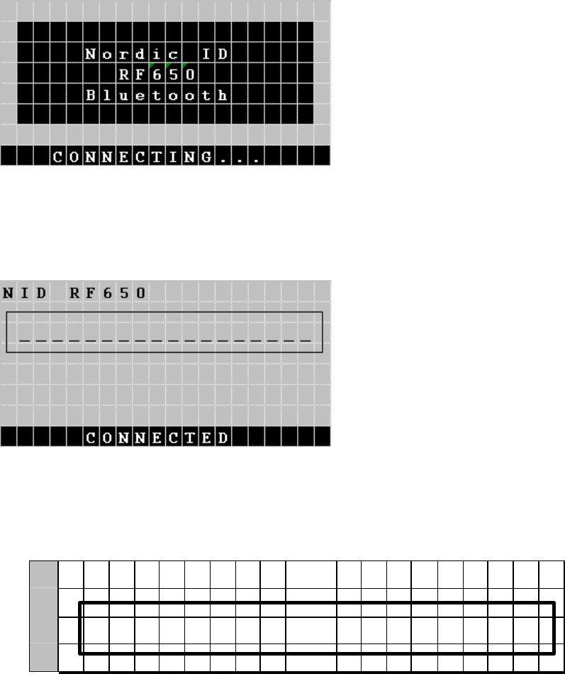
After power-up, the RF650 Hand Terminal will start to search for a WRAP,
and the display will show the following information:
20
After locating the WRAP, the RF650 Hand Terminal and the WRAP will
initiate the connection, and the display will show the following information:
After the RF650 Hand Terminal and the WRAP have the connection defined
and ready for data transfers between the RF650 Hand Terminal and the Host
Application, the display will show the following initial display (for a short time):
An initial display will always appear if no fields are defined. This will usually
occur when the Hand Terminal is activated or its RAM is cleared. The initial
display includes a heading, which may be defined by the user. The input field
consists of max. 18 characters.
0 <
H
E
A
D
I N
G
>
1
2 _
_
_
_
_
_
_
_
_
_
_
_
_
_
_
_
_
_
_
3
A string of characters in the initial display can be sent to the HOST by
pressing the OK button. Alternatively, the field contents may be read using
the Laser Scanner.
21
NOTE! Usually the Host Application has been defined to take control of the
display contents immediately after the connection between the RF650 and the
WRAP has been established.
5.11 Setting the PIN-code
Before the RF650 Hand Terminal can be used in a host application
environment, the PIN-code of the Bluetooth system needs to be set on the
Hand Terminal.
Standard practice is that the system administrator sets the PIN-code on the
Hand Terminal units.
How to set the PIN-code on the RF650 Hand Terminal
The PIN-code is set using the ”Settings” menu on the unit.
1. Press SHIFT + 0 from the keyboard (Shift needs to be pressed down as you press 0)
2. Select “Settings” with the arrow keys and press OK
3. Type in the password (0000-9999), or if it has not been set up, just press OK
4. Select ”PIN code” and press OK
5. Type in a PIN-code between 0000-9999 and press OK
After setting up the PIN-code, a screen that searches for the Base Stations
will appear:
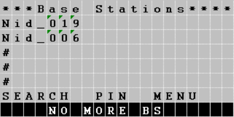
5.12 Searching for the Base Stations
Select [SEARCH] and press OK.
The RF650 Hand Terminal will begin to search for base stations automatically
after power-up and this will usually take 15 – 30 seconds. A list will appear on
the RF650 display listing all the names of the Bluetooth devices nearby.
22
Other Bluetooth devices apart from WRAP (such as mobile phones) may
also appear on the list. The WRAP can be recognized by the name, which the
system administrator has set for it. If there are no WRAPs listed when the text
”NO MORE BS” appears on the display, restart the search process by
selecting [SEARCH]. Select a WRAP, which has the same PIN-code as the
Hand Terminal, from the list and press OK. After selecting the WRAP the
Hand Terminal will form a connection to the WRAP.
After the Hand Terminal has succeeded in connecting with the WRAP the
Hand Terminal will receive the Bluetooth addresses of all the Base Stations
that are connected to the network (have the same PIN-code). The Bluetooth
addresses will be saved in the memory of the Hand Terminal. When the
connection to the network has been successfully performed, the Hand
Terminal will beep three times quickly in succession, after which it will beep
separate beeps one each for a found WRAPs (e.g. five WRAPs found, five
beeps).
The Hand Terminal is now ready to communicate with the host system. The
host system may have a function, which allows only Hand Terminals with a
certain CommID to use the system. The system administrator has to see to it
that CommIDs of all new Hand Terminals to be used in the system are saved
in the host system.
CommID is a unique identification number for the Hand Terminal. By using
the CommID, the Host System is able to separate the Hand Terminals from
each other. CommID is printed on the ID label located under the rechargeable
batteries of the Hand Terminal but may also be checked from the internal
menu (INFO).
5.13 Input fields
The RF650 Hand Terminal has a virtual display page of 12 x 20 characters.
The actual display size is 8 x 20 characters, thus 2/3 of the virtual page can
be viewed at a time.
23
Depending on the application, the HOST can send fields to the Hand
Terminal. These fields may be filled using the keyboard or the Laser Scanner
(or RFID reader). Fields are typically underlined.
5.14 Locked fields
Fields can generally be filled with text using the keyboard. An exception to
this is caused by locked fields. When a locked field is active, the cursor is the
same length as the field. A locked field cannot be read by the Laser Scanner
(or by the RFID reader) either. A locked field functions like a button the
content of which can be sent to the HOST by pressing OK.
5.15 Filling fields using the laser scanner
1. A field can be defined to be filled using the Laser Scanner (or RFID
reader) and sent to the HOST.
2. A field can be defined to be filled using the Laser Scanner (or RFID
reader) but not to be sent to the HOST.
3. A field can be defined not to be filled using the Laser Scanner (or RFID
reader).
NOTE! If a field already contains text, it will be replaced by the new text.
5.16 Writing text in a field
An active field is indicated by the cursor. An active field can be filled with text
using the keyboard and/or using the Laser Scanner (or RFID reader).
You can move the cursor in the field step by step using the arrow keys if
SHIFTLOCK is ON.
5.17 Writing letters
Letters can be written in a field when the SHIFTLOCK is ON by pressing the
number keys containing letters. When a key is pressed once, the first
indicated letter will appear. When pressed twice the second letter will be
shown, and so on.
CAPITAL or small letters can be changed by pressing a key for at least 1.2
seconds.
5.18 Removing letters
24
Letters may be removed from a field with the DEL key.
An entire field can be cleared by pressing the DEL key for at least 0.5
seconds.
5.19 Moving between fields
You can move between the fields using the arrow keys.
By pressing the OK key, you can move to the next field.
5.20 Menu
The settings of the Hand Terminal can be changed through the Menu. The
Menu will be activated by pressing the keys SHIFT + 0.
You can move in the Menu using the arrow keys. The desired item is selected
by pressing the OK key. You can move backwards in the Menu by pressing
OK when the cursor is on the << selection.
NOTE! After choosing an item in the Menu, it must be confirmed by pressing
the OK key. A changed setting will be signalled by a beep.
5.21 Main user settings
The most important settings can be changed using a password (0000 - 9999).
The Initial setting is 0000.
5.22 Adjustments
Key sounds On / Off
Volume Beep level. Three different levels.
Battery 0 for rechargeable batteries
1 for alkaline batteries.
5.23 Info
Information about battery condition (power level) and software version info.
5.24 Versions of the RF650
25
The RF650 is available in three different versions (RF650 with Laser Scanner
for bar codes, RF650 with RFID reader/writer for RFID tags and RF650 with
both the Laser Scanner and the RFID reader/writer.
26
6 Desk Top Charger
6.1 General information
The Desk Top Charger is used for charging the rechargeable batteries of the
RF650 Hand Terminal. It is a fast charger, which reduces the charging time.
Batteries are charged without removing them from the Hand Terminal. The
charging procedure is directed through the Hand Terminal.
6.2 Safety information
The Desk Top Charger includes several safety features. The software of the
Hand Terminal includes a routine, which controls the Desk Top Charger. If the
routine detects that the Hand Terminal contains normal batteries instead of
rechargeable batteries, the charging process is interrupted (max. 10 minutes
from the start of the process). The Hand Terminal charging routine also checks
the functioning of the Desk Top Charger and interrupts the charging process, if
the Desk Top Charger is found to be functioning in an abnormal way.
NOTE! Nordic ID recommends the use of Nordic ID approved/supplied
rechargeable batteries. The use of other brands or normal non-rechargeable
batteries may cause problems.
WARNING! Do not attempt to charge normal alkaline or other normal batteries.
The Desk Top Charger is intended to be used only to charge specified batteries.
WARNING! TO AVOID DAMAGE OR ACCIDENTS, THE DESK TOP
CHARGER MUST NOT BE USED FOR ANY OTHER PURPOSE THAN
THAT STATED IN THIS MANUAL.
6.3 Desk Top Charger system components
• Desk Top Charger
• Power Supply
• Nordic ID approved AA-size rechargeable batteries
27
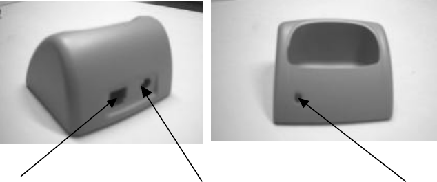
6.4 Connectors
The Desk Top Charger includes 3 connectors:
• Hand Terminal connector
• Power supply connector
• RS232C serial connector
6.5 Charging indicator
The Desk Top Charger has a Charging Indicator (red LED light) located on the left
side of the front part of the casing. See section 6.7 Charging the batteries.
6.6 Battery types
Type of battery 2 pcs rechargeable NiCd or NiMH type size
AA batteries
Charging methods Quick charge and trickle
Charging current 650 mA
Charging time About 1,5 h (with 850 mAh capacity battery)
About 2,5 h (with 1400 mAh capacity battery)
WARNING! To avoid the risk of personal injury or damage to property, do not
attempt to charge non-rechargeable batteries.
RS232 serial connector Power supply (7,5 VDC) Charging indicator
28
6.7 Charging the batteries
WARNING! Do not attempt to charge regular or alkaline batteries as this may cause
an explosion.
Charging batteries using the Desk Top Charger:
• Batteries must be correctly inserted inside the Hand Terminal.
• Please check that the Hand Terminal batteries are of a
rechargeable type (NiCd or NiMH).
• Check that the settings for the Hand Terminal have been
configured as follows:
MENU > ADJUSTMENTS > BATTERY > 0.
• Connect the power adapter to the power supply connector of the
charger (see picture above).
• Place the Hand Terminal in the Desk Top Charger.
• The Charging Indicator LED will remain ON during quick charging.
• The LED will start to blink when the battery is fully charged. The
light of the LED will then be reduced to indicate a trickle charge
current.
The RF650 is placed in the Desk Top Charger by holding the Hand Terminal
lightly with one hand and placing it gently on top of the Desk Top Charger. The
bottom part of the Hand Terminals casing fits the shape of the large opening on
top of the Desk Top Charger. Gently push the Hand Terminal down until the
connectors mate (a low beep followed by a high beep are generated from the
Hand Terminal if the Desk Top Charger is connected to a power supply, which in
turn is connected to a power outlet). See the picture below.
29
NOTE! The Desk Top Charger may only be used with the Power
Supply provided by the manufacturer.
The Hand Terminal cannot be used during battery charging.
It is normal for the base of the charger to warm during charging.
6.7.1 Audio signals and the Charging Indicator LED
Charging indicator
Quick charge The LED remains on
Trickle charge The LED (red) blinks
Audio signals
Three successive beeps Charging not allowed (the Hand Terminal
does not contain rechargeable batteries).
Two successive beeps (long-short) The battery is being charged
30
7 Installation and use
7.1 Basic installation of the RF650 Hand Terminal
Basic Installation of the RF650 Hand Terminal is straightforward. Select a place for the
Desk Top Charger, in which the Hand Terminal can be stored when not in use. Avoid
direct sunlight, extreme temperatures and wet or humid surroundings. The RF650 is
intended for indoor use.
7.2 Installation of the WRAP
The WRAP should be installed according to the instructions in the product manual for
the WRAP.
Specific instructions for use are usually provided by the System Integrator providing
the Host Application solution to the customer.
31
8 Appendix
The Appendix contains useful information, contact addresses and other additional
information regarding the products mentioned in this User’s Manual or products
otherwise useful in connection of using the RF650, WRAP or system.

32
8.1 Technical specifications of the RF650 Hand Terminal
Technical Data
Operating
frequency 2400 to 2483.5 MHz (ISM radio band)
Transmit power Power class 1 (+4 to +20 dBm)
Antenna gain 0 dBi
Data transfer rate
721 Kbit/s Asymmetric, 432.6 Kbit/s Symmetric
Operating
temperature 0 to +60 Celsius (32 to 140 Fahrenheit)
Hand Terminal
Size L x H x W 173 x 22(41) x 54 (79) mm
Weight incl.
batteries 257 g with barcode scanner (0,567 lbs)
237 g without barcode scanner (0,523 lbs)
Power supply 2 pcs AA-size rechargeable batteries NiMH / NiCd or normal
alkaline batteries
Voltage range Min 2 V, typical 2.4 V, max 3.3 V
Display 8 x 20 characters with backlight
Keyboard 22 silicone rubber keys
Barcode support All common types
User input By keyboard, barcode scanner or RFID reader / writer (13.56
MHz and 125 kHz)
Drop resistance From a height of 1 m on to concrete
WRAP
Size L x H x W 130 x 80 x 35 mm
Power Supply Input: 100 - 240 VAC 50Hz / 60Hz Output: 12 VDC, 830 mA
Interface
2 x RS232: 19200, N, 8, 1 (CTS/RTS) Connectors
Modular 6-pin RJ45 for Ethernet
DC-jack for power supply

33
Product Highlights
RS232 interface for connecting to external devices
Highly ergonomic design
Light weight and compact
Easy to use one hand operation
Integrated antenna
7 terminals communicate simultaneously with the WRAP (may vary depending on
model)
WRAP can also be used relay mode and in “site survey” mode
Integrated barcode scanner and/or RFID reader/writer
8.2 Technical specifications of the Desk Top Charger
Rechargeable batteries 2 pcs size AA NiCd or NiMH rechargeable battery
Charging methods Quick charge and trickle charge modes
Power Supply Input: 100 - 240 VAC 50Hz / 60Hz
Output: 7,5 VDC, 1200 mA
Charging current 650 mA
Charging time About 1,5 h (with 850 mAh capacity battery)
About 2,5 h (with 1400 mAh capacity battery)
34
8.3 Minimum system requirements for software installation
The specific requirements for the installation of the RF650 Hand Terminal into
any system are based on the Bluetooth 1.1 Standard and require the use of a
compliant WRAP (Wireless Remote Access Platform).
The specific requirements for the installation of the WRAP (Wireless Remote
Access Platform) into any system are based on the Bluetooth 1.1 Standard for
the radio part and on the applicable network connection method (LAN, GPRS
etc.). Detailed requirements for the WRAP can be found from the documentation
of the WRAP.
The RF650 Hand Terminal and the WRAP contain all the necessary software
required to establish, maintain and end the radio communication link between the
Hand Terminal and the WRAP.
The connection of the WRAP into the host application depends on the host
system hardware and operating system and the host application software. The
specifications are usually checked and verified by the System Integrator.
For further information, please contact Nordic ID Technical Support.
8.4 Useful links
The following links contain useful information relating to either Nordic ID,
Bluetooth or related subjects:
Nordic ID http://www.nordicid.com
Bluetooth http://www.bluetooth.com
WRAP http://www.bluegiga.com

35
8.5 Trademarks
Nordic ID and Nordic ID logo are registered trademarks of Nordic ID Oy.
All terms mentioned in this User's Guide that are known to be trademarks or service
marks have been appropriately marked in the list below with either the ©, ® or the ™
symbol.
Nordic ID cannot attest to the accuracy of this information. Use of a term in this User's
Guide should not be regarded as affecting the validity of any trademark or copyright.
Company / Owner of the Trademark
Trademark
Bluegiga Technologies WRAP ©
Bluetooth SIG inc. Bluetooth ©
8.6 Programming the RF650 laser scanner module
A laser diode produces a single beam of coherent light, which deflects off a mirror,
and is emitted from the laser engine used inside the RF650. The total deflection of the
single beam is 53° (standard version), and the scan frequency is 39 scans per
second.
When the laser beam strikes a bar code, the dark bars absorb most of the light while
the light spaces reflect most of it. Thus, changes in the reflected light can be used to
deduce the bar code into electronic format. A photo diode is used to sense the
reflected laser light and generate a current proportional to the reflected light signal.
The current then produces an analogue voltage, which is further amplified, filtered to
minimise noise related problems and then finally sent to a digitiser, which transforms
the analogue signal into digital form repres
enting the bar code.
The DBP data is then sent to the decoder board for processing into a host-compatible
format and further applications are based on the software used.
Technical specifications
The technical specifications of the laser engine used in the RF650 are listed in the
table below.

36
ITEM SPECIFICATION
Scan repetition rate 39 (± 3) scans/sec (bi-directional)
Laser power 1.2mW nominal (Scanning Mode)
0.8mW nominal (Aim Mode)
Laser Class IEC Class 2 devices
Print contrast Minimum 25% absolute dark/light
reflectance measured at 650nm
Scan angle 53º (typical)
Ambient Light Immunity
• Sunlight
• Artificial light
10 000 ft. candles / 107.640 lux
450 ft. candles / 4.844 lux
Usable scan distance depends on the bar code size and pitch, quality of the bar code
print and ambient light conditions as well as the pitch and angle of the laser beam in
reference to the bar code surface. Further information available from Nordic ID upon
request.
The laser engine used in the RF650 is programmed during the manufacturing process
by defining certain operational parameters with default values. These values may be
changed by the user by first setting the unit into a special programming mode and
then by scanning special bar codes listed below.
User programmable parameters with detailed descriptions and the respective bar
codes are listed in the following chapters and the factory default values are listed in
the next section starting at next page.

37
8.7 Default factory settings of the Laser engine
DEFAULT PARAMETER SETTINGS OF RF650 LASER ENGINE
Parameter Parameter number Default setting
Linear Code Type Security
Levels 0x4E 1
UPC-A 0x01 Enable
UPC-E 0x02 Enable
UPC-E1 0x0C Disable
EAN-8 0x04 Enable
EAN-13 0x03 Enable
Bookland EAN 0x53 Disable
Decode UPC/EAN
Supplementals 0x10 Ignore
Decode UPC/EAN
Supplemental redundancy 0x50 7
Transmit UPC-A Check Digit 0x28 Enable
Transmit UPC-E Check Digit 0x29 Enable
Transmit UPC-E1 Check Digit 0x2A Enable
UPC-A Preamble 0x22 System Character
UPC-E Preamble 0x23 System Character
UPC-E1 Preamble 0x24 System Character
Convert UPC-E to A 0x25 Disable
Convert UPC-E1 to A 0x26 Disable
EAN-8 Zero Extend 0x27 Disable
Convert EAN-8 to EAN-13
Type 0xE0 Type is EAN-13
UPC/EAN Security Level 0x4D 0
UPC/EAN Coupon Code 0x55 Disable
USS-128 0x08 Enable
UCC/EAN-128 0x0E Enable
ISBT 128 0x54 Enable
Code 39 0x00 Enable
Trioptic Code 39 0x0D Disable
Convert Code 39 to Code 32 0x56 Disable
Code 32 Prefix 0xE7 Disable
Set Length(s) for Code 39 0x12 / 0x13 2-55
Code 39 Full Ascii Conversion 0x11 Disable
Code 93 0x09 Disable
Set Length(s) for Code 93 0x1A / 0x1B 4-55
Interleaved 2 of 5 0x06 Enable
Set Length(s) for I 2 of 5 0x16 / 0x17 14
Interleaved 2 of 5 Check Digit
0x31 Disable

38
Verification
Transmit Interleaved 2 of 5
Check Digit 0x2C Disable
Convert Interleaved 2 of 5 EAN
13 0x52 Disable
Discrete 2 of 5 0x05 Disable
Set Length(s) for Discrete 2 of
5 0x14 / 0x15 12
Codabar 0x07 Disable
Set Lengths for Codabar 0x18 / 0x19 5-55
CLSI Editing 0x36 Disable
NOTIS Editing 0x37 Disable
MSI Plessey 0x0B Disable
Set Length(s) for MSI Plessey 0x1E / 0x1F 6-55
MSI Plessey Check Digits 0x32 One
Transmit MSI Plessey Check
Digit 0x2E Disable
MSI Plessey Check Digit
Algorithm 0x33 Mod 10 / Mod 10
Transmit Code ID Character 0x2D None
Table 5: Default factory settings
Scanning this bar code returns all Laser engine parameters to factory default values,
which are listed in the table above.
SET ALL DEFAULTS
39
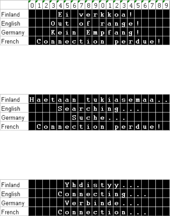
8.8 Status messages of RF650 Hand Terminal
International end-users of RF650 will see different kind of status messages on
the bottom of the Hand Terminal screen. There is possible to change a language
of status messages by changing configuration bit in eeprom memory. Space for
the status message is one line and 20 characters. Characters sets of these
languages are Latin-1. If needed a different character set like Russian Cyrillic or
Hebrew may be used but this implies that the firmware of the Hand Terminal is
changed.
8.9 “Out of Range!”
When connection drops: “Out of range” status appears.
8.10 “Searching”
RF650 searches for WRAPs (base stations)
8.11 “Connecting…”
RF650 has found the WRAP and connection is about to established.
40
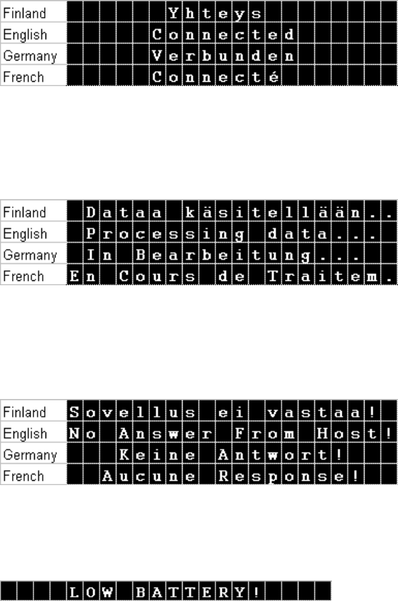
8.12 “Connected!
Connection with the WRAP has been established!
8.13 “Processing data!
Host Application has processed data and the Hand Terminal is waiting for an
answer.
8.14 “No answer from Host”
If the Host Application doesn’t answer the “No answer from host” message
appears and error beeps are also generated.
8.15 “Battery low”
Warning is generated when a low battery status is detected.
41
8.16 Frequently asked questions
Q: What are the specifications of the integrated laser scanner that RF650 has?
A: It is a high quality laser scanner with a scan angle of 48 degrees, skew
tolerance < 55 degrees and pitch angle < 65 degrees. The contrast ration is 30
%.
Q: Can Nordic ID RF650 Hand Terminals read Interleaved 2/5 barcode?
A: It is possible to enable and disable the decode of different Barcode
Symbologies by configuring the laser scanner (please see the RF650 Laser
Scanner Module Programming Manual). RF650 supports the most common
barcodes.
Q: What is the reading distance of the laser scanner?
A: We are using a Symbol laser engine in RF650, which support the most
common barcodes, and the reading distance is about 10 - 80 cm.
8.17 Service and Support contacts
If the Hand Terminal is not functioning properly, please contact primarily the
reseller/supplier of the products.
Before contacting Nordic ID Service or Nordic ID Technical Support please note
the serial number(s) of the Hand Terminal(s) and/or WRAP(s) which seem to be
causing the problems before calling. You can contact Nordic ID Service and
Nordic ID Technical Support through your supplier or optionally, you may send
an email with the above-mentioned information along with your description of the
problem and your full contact information to support@nordicid.com. Please
remember to include information regarding the provider of the host application
used with the RF650 System.
42
8.18 Sending the unit to service (Service Report Form)
Before sending the unit to service, please contact Nordic ID Service or a Nordic
ID Service Partner or Nordic ID Technical Support.
Please have at hand the type of product in question, the serial number(s) of the
product(s) and the software version.
If your problem requires servicing of the unit(s), you will receive a Return
Authorisation Code, which must be included along with the return address,
invoicing information/address and a description of the problem in the packing of
the unit(s) to be serviced.
A form for filling in the required information can be downloaded/printed from
Nordic ID Support Internet page at the address http://www.nordicid.com.
You may also use the Service Report form (see following page).

43
HEADER _______________ (*)
Service Report form
Company name ____________________________________________________
Contact person _______________________________________________________
E-mail address ________________________________________________________
Telephone __________________________ Fax _____________________
Return address________________________________________________________
Invoicing address ______________________________________________________
Return method normal express
Date of purchase ____________________ Type of the device _______________
Hardware supplier______________________________________________________
System Integrator ______________________________________________________
Serial number (*) ______________________________________________________
Software version ______________________________________________________
Fault description of the device (in detail if possible)
____________________________________________________________________
____________________________________________________________________
____________________________________________________________________
Do you wish to have a repair cost estimate before the service (circle appropriate
YES NO
Do you wish to have an express repair (circle appropriate) (**)
YES NO
(**) (if yes, the extra costs will be charged according to the valid service price list)
(continued on next page)

44
The Manufacturer grants to the Product a warranty of one year. Manufacturer warrants
that the Product is free from defects in materials and workmanship under normal use
during the warranty period. The Product shall be returned to the Manufacturer for
repair in such cases, as the Customer cannot remedy the problem of error in the unit.
Each party will bear the cost of freight to the intended destination of the item to be
repaired. Repair service done by manufacturer after the warranty period will be
charged according to the valid service price list.
(*) You may continue on additional sheets if necessary, but please mark all related
pages with the same header (e.g. your company name and running page number).
45
8.19 Contact information
Nordic ID International Headquarters Nordic ID Sweden
Nordic ID Oy Nordic ID
Myllyojankatu 2 A Stora Åsvägen 21
FIN-24100 SALO S-436 34 Askim
FINLAND SWEDEN
Telephone: +358 2 727 7700 Telephone: +46 31 720 86 46
Fax: +358 2 727 7720 Fax: +46 31 700 86 95
Internet: www.nordicid.com Internet: www.nordicid.com
Email: info@nordicid.com Email: info@nordicid.se
Nordic ID United States Nordic ID Germany
Nordic ID
Nordic ID Gmbh
2810 Mt Tabor Ch Rd Hchstr. 26
Dallas 32051 Herford
GA 30157, USA GERMANY
Telephone: +1 770 445 0095 Telephone: +49 5221 101 4600
Fax: +1 770 445 5185 Fax: +49 5221 101 4601
Internet: www.nordicid.com Internet: www.nordicid.de
Email us_sales@nordicid.com Email: info@nordicid.de
Nordic ID United Kingdom Nordic ID France
Nordic ID Ltd Nordic ID
Clifford Mill, Clifford Chambers 30, rue Godot de Mauroy
Stratford-upon-Avon, Warwickshire 75009 Paris
CV37 HW8 UNITED KINGDOM FRANCE
Telephone: +44 1789 294 799 Telephone: +33 1 53 30 41 80
Fax: +44 1789 294 739 Fax: +33 1 53 30 41 81
Internet: www.nordicid.com Internet: www.nordicid.com
Email: sales@nordicid.co.uk Email: commercial@nordicid.com