Nordic Track Ntsr019091 Owner S Manual 285430
2014-07-06
: Nordic-Track Nordic-Track-Ntsr019091-Owner-S-Manual nordic-track-ntsr019091-owner-s-manual nordic-track pdf
Open the PDF directly: View PDF ![]() .
.
Page Count: 28
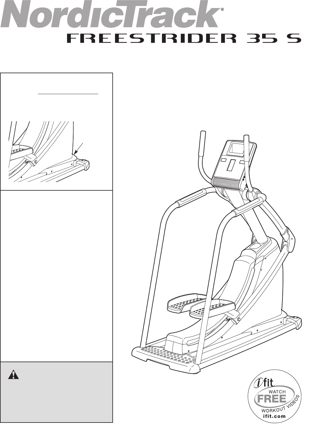
Model No. NTSR01909.1
Serial No.
Write the serial number in the space
above for reference.
USERʼS MANUAL
Serial
Number
Decal
CAUTION
Read all precautions and instruc-
tions in this manual before using
this equipment. Keep this manual
for future reference.
www.nordictrack.com
QUESTIONS?
If you have questions, or if parts are
damaged or missing, DO NOT
CONTACT THE STORE; please
contact Customer Care.
IMPORTANT: Please register this
product (see the limited warranty
on the back cover of this manual)
before contacting Customer Care.
CALL TOLL-FREE:
1-888-825-2588
Mon.–Fri. 6 a.m.–6 p.m. MT
Sat. 8 a.m.–4 p.m. MT
ON THE WEB:
www.nordictrackservice.com
2
TABLE OF CONTENTS
WARNINGDECALPLACEMENT ..............................................................2
IMPORTANTPRECAUTIONS ................................................................3
BEFOREYOUBEGIN ......................................................................4
ASSEMBLY ...............................................................................5
HOWTOUSETHECHESTPULSESENSOR...................................................11
HOWTOUSETHEELLIPTICALSTRIDER.....................................................12
MAINTENANCEANDTROUBLESHOOTING ...................................................20
EXERCISEGUIDELINES ...................................................................21
PARTLIST ..............................................................................23
EXPLODEDDRAWING ....................................................................25
ORDERINGREPLACEMENTPARTS ..................................................BackCover
LIMITEDWARRANTY ..............................................................BackCover
NordicTrack is a registered trademark of ICON IP, Inc.
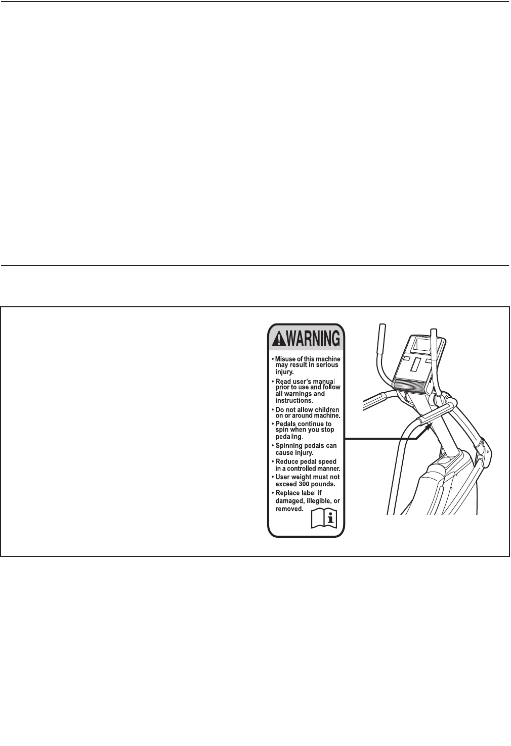
WARNING DECAL PLACEMENT
This drawing shows the location(s) of the warning
decal(s). If a decal is missing or illegible, see
the front cover of this manual and request a
free replacement decal. Apply the decal in the
location shown. Note: The decal(s) may not be
shown at actual size.

3
WARNING: To reduce the risk of serious injury, read all important precautions and
instructions in this manual and all warnings on your elliptical strider before using your elliptical
strider. ICON assumes no responsibility for personal injury or property damage sustained by or
through the use of this product.
IMPORTANT PRECAUTIONS
1. Before beginning any exercise program,
consult your physician. This is especially
important for persons over age 35 or per-
sons with pre-existing health problems.
2. It is the responsibility of the owner to ensure
that all users of the elliptical strider are ade-
quately informed of all precautions.
3. The elliptical strider is intended for home
use only. Do not use the elliptical strider in a
commercial, rental, or institutional setting.
4. Keep the elliptical strider indoors, away from
moisture and dust. Place the elliptical strider
on a level surface, with a mat beneath it to
protect the floor or carpet. Make sure that
there is at least 3 ft. (1 m) of clearance in the
front and rear of your elliptical strider and 2
ft. (0.6 m) on each side.
5. Inspect and properly tighten all parts regu-
larly. Replace any worn parts immediately.
6. Keep children under age 12 and pets away
from the elliptical strider at all times.
7. The elliptical strider should not be used by
persons weighing more than 300 lbs.
(136 kg).
8. Wear appropriate exercise clothes while
using the elliptical strider. Always wear ath-
letic shoes for foot protection while exercis-
ing.
9. Hold the handlebars or the handrails when
mounting, dismounting, or using the ellipti-
cal strider.
10. The pulse sensor is not a medical device.
Various factors may affect the accuracy of
heart rate readings. The pulse sensor is
intended only as an exercise aid in determin-
ing heart rate trends in general.
11. Keep your back straight while using the
elliptical strider; do not arch your back.
12. Over exercising may result in serious injury
or death. If you feel faint or if you experience
pain while exercising, stop immediately and
cool down.
13. When you stop exercising, allow the pedals
to slowly come to a stop.
14. Use the elliptical strider only as described in
this manual.
4
BEFORE YOU BEGIN
Thank you for selecting the revolutionary
NordicTrack®FREESTRIDER 35 S elliptical strider.
The FREESTRIDER 35 S elliptical strider provides a
wide array of features designed to make your work-
outs more effective and enjoyable.
For your benefit, read this manual carefully before
you use the elliptical strider. If you have questions
after reading this manual, see the front cover of this
manual. To help us assist you, note the product num-
ber and serial number before contacting us. The
model number and the location of the serial number
decal are shown on the front cover of this manual.
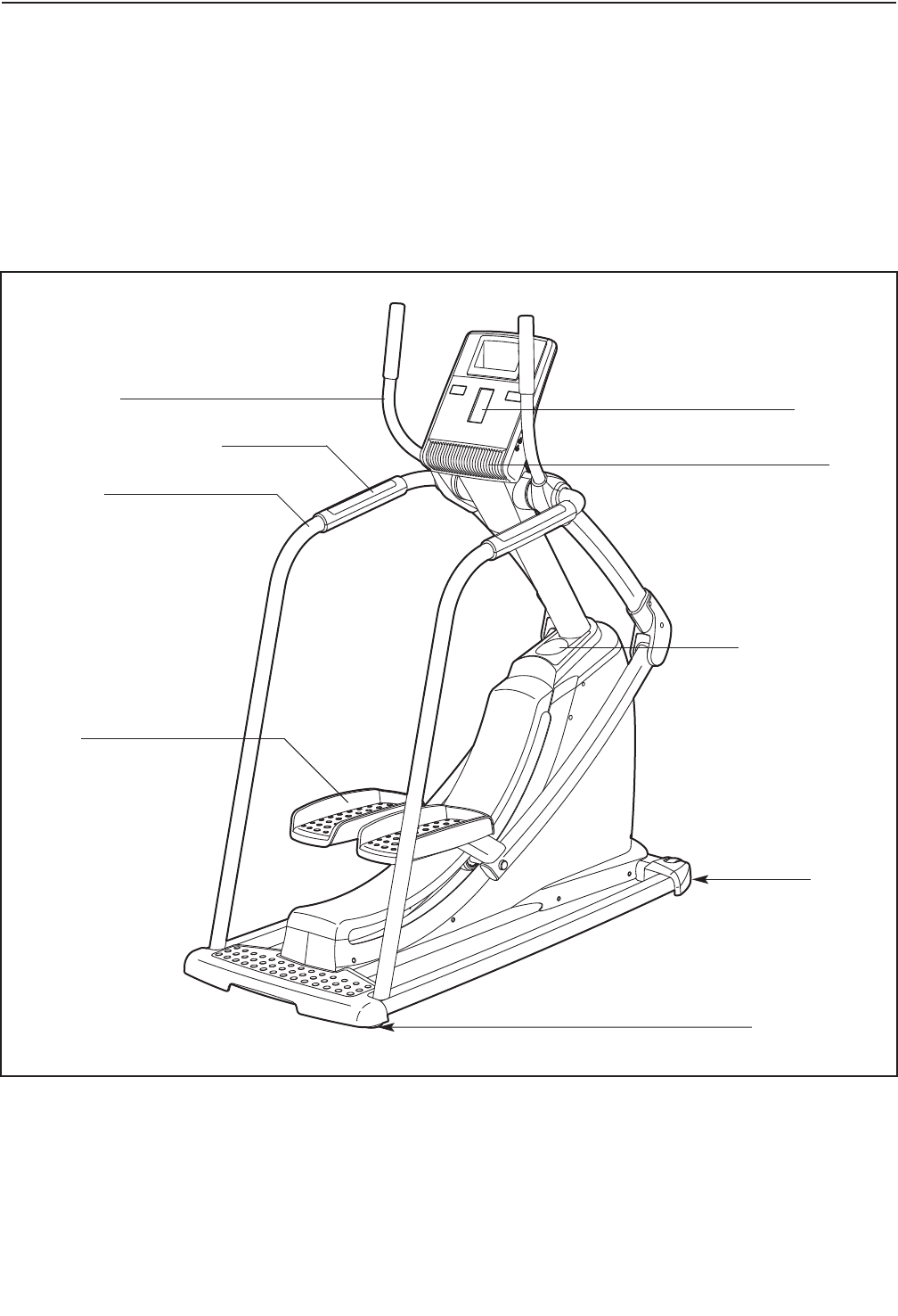
Before reading further, please familiarize yourself with
the parts that are labeled in the drawing below.
Handrail
Wheel
Pedal
Console
Accessory Tray
Leveling Foot
Handlebar
Handgrip Pulse Sensor
Fan
5
ASSEMBLY
Assembly requires two persons. Place all parts of the elliptical strider in a cleared area and remove the pack-
ing materials. Do not dispose of the packing materials until assembly is completed.
In addition to the included tool(s), assembly requires a Phillips screwdriver .
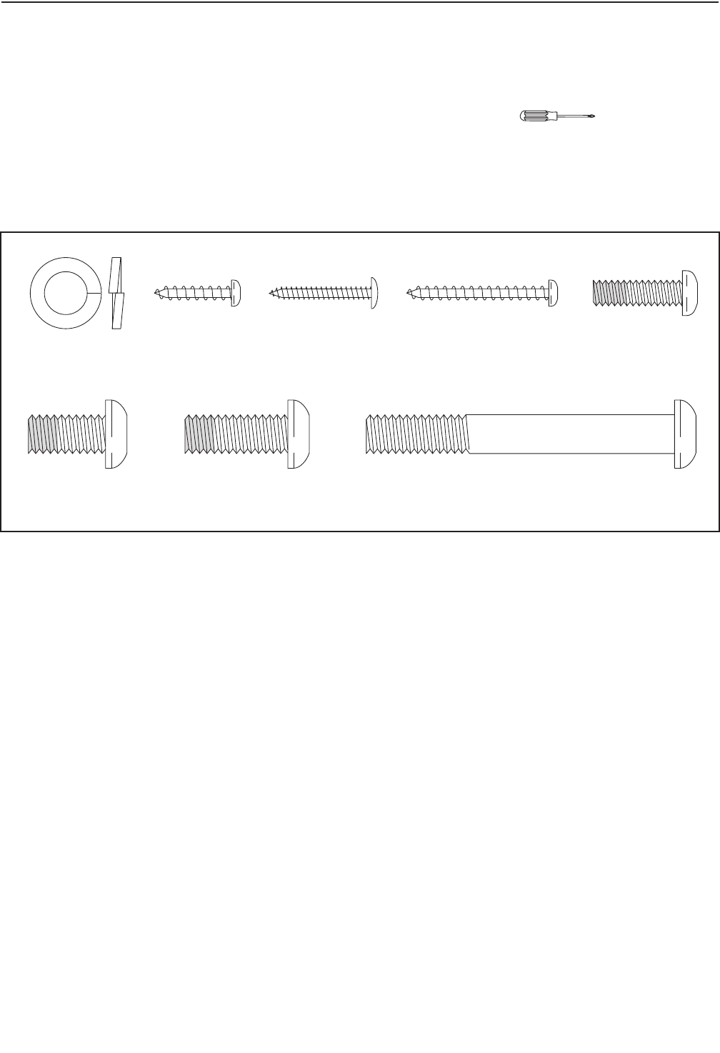
As you assemble the elliptical strider, use the drawings below to identify small parts. The number in parentheses
below each drawing is the key number of the part, from the PART LIST near the end of this manual. The number
following the parentheses is the quantity needed for assembly. Note: Some small parts may have been pre-
assembled. If a part is not in the hardware kit, check to see if it has been preassembled.
3/8" x 1" Patch
Screw (122)–4
3/8" x 3/4" Patch
Screw (123)–2
3/8" x 3" Screw
(124)–2
1/4" x 3/4" Patch
Screw (127)–4
M10 Split
Washer (128)–2
#8 x 3/4"
Screw (86)–12
#8 x 1" Tek
Screw (126)–8
#8 x 35mm
Screw (125)–1
6
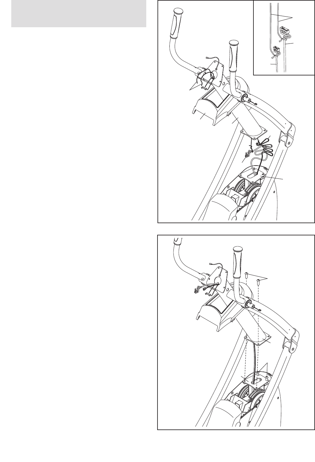
1.
IMPORTANT: Do not remove the foam block
(not shown) located under the pedals until
you have completed step 2.
Identify the Shield Cap (5) and the Upright (26)
and orient them as shown. Slide the Shield Cap
upward around the Upright.
While another person holds the Upright (26)
near the Frame (1), locate the wire ties in the
Upright.
See the inset drawing. Tie the lower end of a
wire tie to the end of the Wire Harness (77).
Pull the other end of the wire tie upward out of
the top of the Upright (26).
Next, tie the lower end of the other wire tie to
the end of the Power Cable (81). Pull the other
end of the wire tie upward out of the top of the
Upright (26).
Then, untie and discard the wire ties.
1
81
5
1
Wire
Ties
77
26
77
81
Wire
Ties
2. Tip: Avoid pinching the wires. Attach the
Upright (26) to the Frame (1) with four 3/8" x 1"
Patch Screws (122). Note: Two of the Patch
Screws may be preattached to the Frame. Tip:
Start all the Patch Screws before tightening
any of them.
Remove and discard the foam block (not
shown) located under the pedals.
2
122
122
1
26
Avoid pinching
the wires
To make assembly easier, read the
information on page 5 before you begin.
7
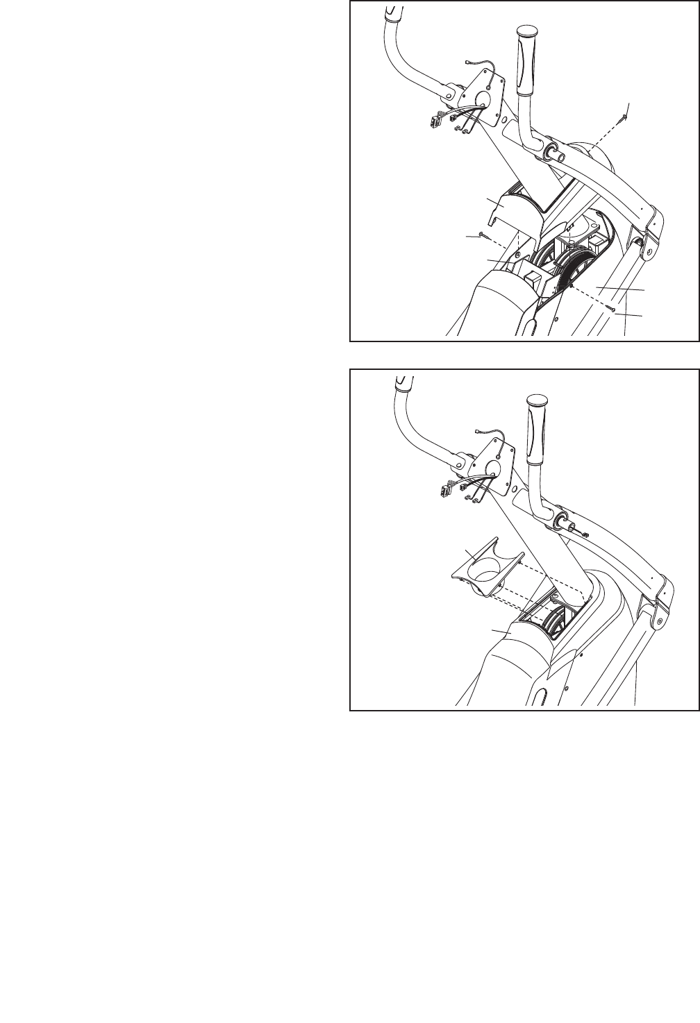
3. Slide the Shield Cap (5) downward over the
Right and Left Shields (6, 7).
Attach the Shield Cap (5) with a #8 x 35mm
Screw (125) and two #8 x 3/4" Screws (86).
Tip: Start all the Screws before tightening
any of them.
3
86
86
6
125
5
7
4. Orient the Accessory Tray (18) as shown. Press
the Accessory Tray into the Shield Cap (5). 4
5
18
8
5. Identify the Right Handrail (69), which is marked
with a “Right” sticker.
While another person holds the Right Handrail
(69) near the Upright (26), connect the right
Pulse Wire (78) to the right Sensor Wire (79).
Insert the excess wire into the Right Handrail
(69). Then, slide the Right Handrail onto the
Upright (26).
Tip: Avoid pinching the wires. Attach the
Right Handrail (69) with a 3/8" x 3/4" Patch
Screw (123) and an M10 Split Washer (128).
Do not tighten the Patch Screw yet.
Repeat this step for the Left Handrail (70).
5
69
128
123
79
26
70
78
30
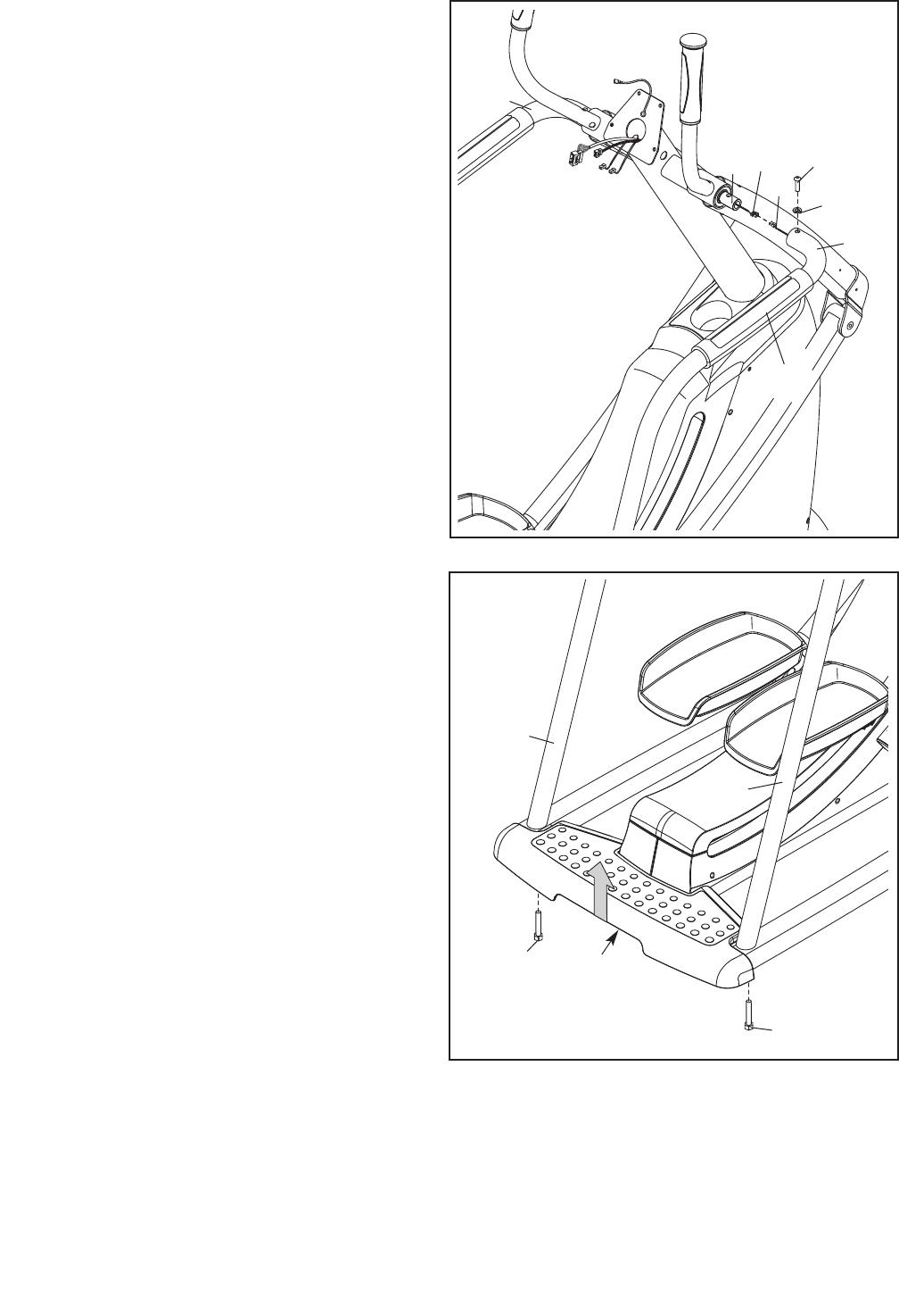
6. IMPORTANT: To prevent damage, do not
allow the elliptical strider to tip to either side
during this step.
While another person lifts the rear of the Frame
(1) in the location shown by the arrow, attach
each Handrail (69, 70) to the Frame with a 3/8"
x 3" Screw (124).
See step 5. Tighten the 3/8" x 3/4" Patch
Screws (123).
6
124
124
69
1
70
Avoid pinching
the wires

9
7. While another person holds the Console (4)
near the Upright (26), connect the console wires
to the Wire Harness (77), the Power Cable (81),
and the Ground Wire (82). Then, connect the
console pulse wires to the Pulse Wires (78).
Insert the excess wire downward into the
Upright (26).
Tip: Avoid pinching the wires. Attach the
Console (4) to the Upright (26) with four 1/4" x
3/4" Patch Screws (127).
7
127
77
81 82
26
78
Pulse
Wires
Console
Wires
4
8. Identify the Front and Rear Shields (10, 13) and
orient them as shown.
Attach the Front and Rear Shields (10, 13)
around the Upright (26) with six #8 x 3/4"
Screws (86).
8
26
13
10
86
Avoid pinching
the wires
10
14
86
20
21
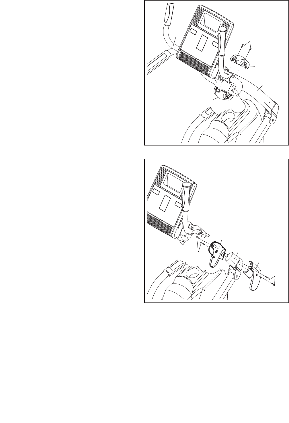
9. Identify the Right Upper and Lower Covers (14,
15), which are marked with “Right” stickers, and
orient them as shown.
Attach the Right Upper and Lower Covers (14,
15) around the Right Handlebar (20) with two
#8 x 3/4" Screws (86).
Repeat this step for the Left Handlebar (21).
9
15
10. Identify a set of Right and Left Link Covers (22,
23), which are marked with “Right” and “Left”
stickers, and orient them as shown.
Attach the Right and Left Link Covers (22, 23)
around the Right Handlebar (20) with four #8 x
1" Tek Screws (126).
Repeat this step for the other side of the
elliptical strider.
10
20
126
126
23
22
11. Plug the AC power adapter into the jack on the front of the elliptical strider (see HOW TO PLUG IN THE AC
POWER ADAPTER on page 12). IMPORTANT: If the elliptical strider has been exposed to cold temper-
atures, allow it to warm to room temperature before plugging in the AC power adapter. If you do not
do this, you may damage the console displays or other electronic components.
Make sure that all parts are properly tightened before you use the elliptical strider. Note: After assembly
is completed, some extra parts may be left over. Place a mat beneath the elliptical strider to protect the floor.
11
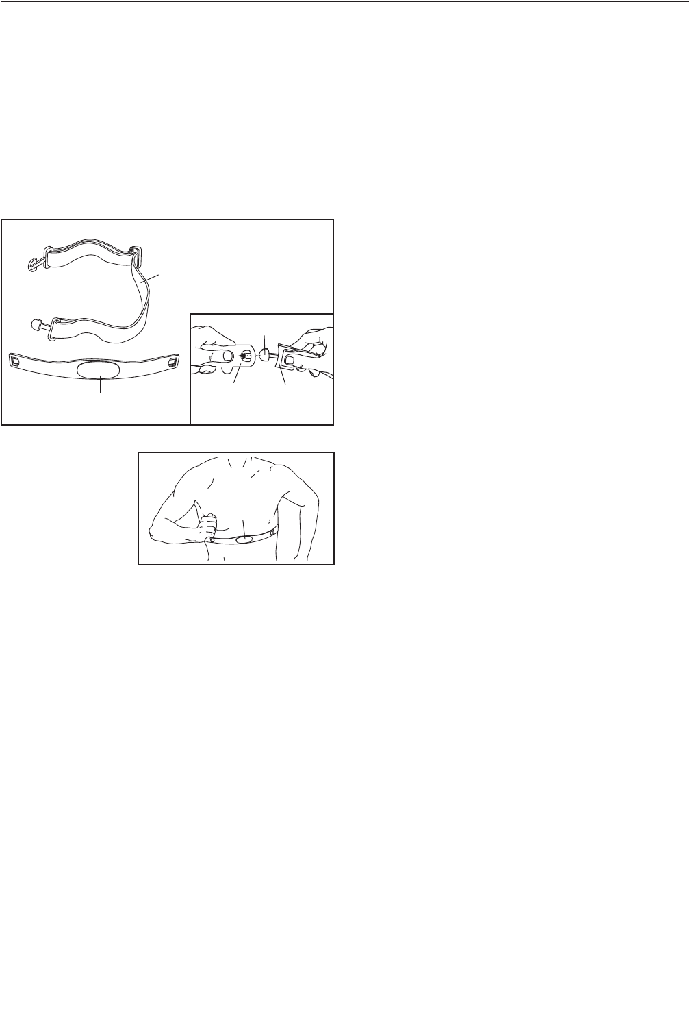
HOW TO PUT ON THE CHEST PULSE SENSOR
The chest pulse sensor has two components: a chest
strap and a sensor unit (see the drawing below). Insert
the tab on one end of the chest strap into one end of
the sensor unit, as shown in the inset drawing. Press
the end of the sensor unit under the buckle on the
chest strap. The tab should be flush with the front of
the sensor unit.
Next, wrap the
chest pulse sensor
around your chest
and attach the
other end of the
chest strap to the
sensor unit. Adjust
the length of the
chest strap, if necessary. The chest pulse sensor
should be under your clothes, tight against your skin,
and as high under the pectoral muscles or breasts as
is comfortable. Make sure that the logo on the sensor
unit is facing forward and is right-side-up.
Pull the sensor unit away from your body a few inches
and locate the two electrode areas on the inner side
(the electrode areas are covered by shallow ridges).
Using saline solution such as saliva or contact lens
solution, wet both electrode areas. Return the sensor
unit to a position against your chest.
CHEST PULSE SENSOR CARE
• Dry the chest pulse sensor after each use. The
chest pulse sensor is activated when you wet the
electrode areas and put on the chest pulse sensor;
the chest pulse sensor shuts off when it is removed
and the electrode areas are dried. If the chest pulse
sensor is not dried after each use, the battery may
be drained prematurely.
• Store the chest pulse sensor in a warm, dry place.
Do not store the chest pulse sensor in a plastic bag
or other container that may trap moisture.
• Do not expose the chest pulse sensor to direct sun-
light for extended periods of time or to temperatures
above 122° F (50° C) or below 14° F (-10° C).
• Do not excessively bend or stretch the sensor unit
when using or storing the chest pulse sensor.
• Clean the sensor unit using a damp cloth—never
use alcohol, abrasives, or chemicals. Hand wash
and air dry the chest pulse sensor.
CHEST PULSE SENSOR TROUBLESHOOTING
If the chest pulse sensor does not function prop-
erly, try the suggestions below.
• Make sure that you are wearing the chest pulse sen-
sor as described at the left. Note: If the chest pulse
sensor does not function when positioned as
described, move it slightly lower or higher on your
chest.
• Use saline solution such as saliva or contact lens
solution to wet the two electrode areas on the sen-
sor unit. If heart rate readings do not appear until
you begin perspiring, re-wet the electrode areas.
• Position yourself near the console. For the console
to display heart rate readings, the user must be
within armʼs length of the console.
• The chest pulse sensor is designed to work with
people who have normal heart rhythms. Heart rate
reading problems may be caused by medical condi-
tions such as premature ventricular contractions
(pvcs), tachycardia bursts, and arrhythmia.
• The operation of the chest pulse sensor can be
affected by magnetic interference caused by high
power lines or other sources. If it is suspected that
this is a problem, try relocating the elliptical strider.
HOW TO USE THE CHEST PULSE SENSOR
Chest Strap
Sensor Unit
Tab
Buckle
Sensor
Unit
Logo
12
HOW TO USE THE ELLIPTICAL STRIDER
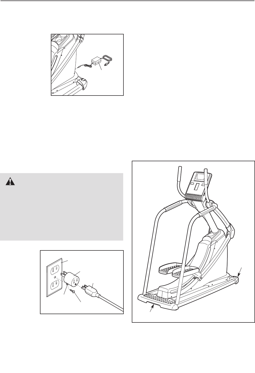
HOW TO PLUG IN THE AC POWER ADAPTER
This product
must be
grounded. If it
should malfunc-
tion or break
down, grounding
provides a path of
least resistance
for electric current
to reduce the risk
of electric shock.
This product is
equipped with an AC power adapter having an equip-
ment-grounding conductor and a grounding plug. Plug
the AC power adapter into the jack on the front of
the elliptical strider. Then, plug the AC power
adapter into an appropriate outlet that is properly
installed and grounded in accordance with all
local codes and ordinances. This product is for
use on a nominal 120-volt circuit. IMPORTANT:
The elliptical strider is not compatible with GFCI-
equipped outlets.
A temporary
adapter may
be used to
connect the
power cord
to a 2-pole
receptacle as
shown at the
right if a
properly
grounded
outlet is not
available. The temporary adapter should be used only
until a properly grounded outlet can be installed by a
qualified electrician.
The green-colored rigid ear, lug, or the like extending
from the adapter must be connected to a permanent
ground such as a properly grounded outlet box cover.
Whenever the adapter is used, it must be held in
place by a metal screw. Some 2-pole receptacle out-
let box covers are not grounded. Contact a quali-
fied electrician to determine if the outlet box cover
is grounded before using an adapter.
HOW TO MOVE THE ELLIPTICAL STRIDER
Due to the size and weight of the elliptical strider,
moving it requires two persons. Have two persons
lift the indicated end of the elliptical strider until the
elliptical strider will roll on the front wheels. Carefully
move the elliptical strider to the desired location and
then lower it to the level position. CAUTION: To
decrease the risk of injury, bend your legs and
keep your back straight. Make sure to use your
legs rather than your back to lift the elliptical
strider. Do not attempt to move the elliptical
strider over an uneven surface.
DANGER: Improper connection of
the equipment-grounding conductor can
result in an increased risk of electric shock.
Check with a qualified electrician or service-
man if you are in doubt as to whether the
product is properly grounded. Do not modify
the plug provided with the product—if it will
not fit the outlet, have a proper outlet installed
by a qualified electrician.
Grounded Outlet Box
Power Cord
Adapter
Lug
Metal Screw
AC Power
Adapter
Wheel
Lift here
13
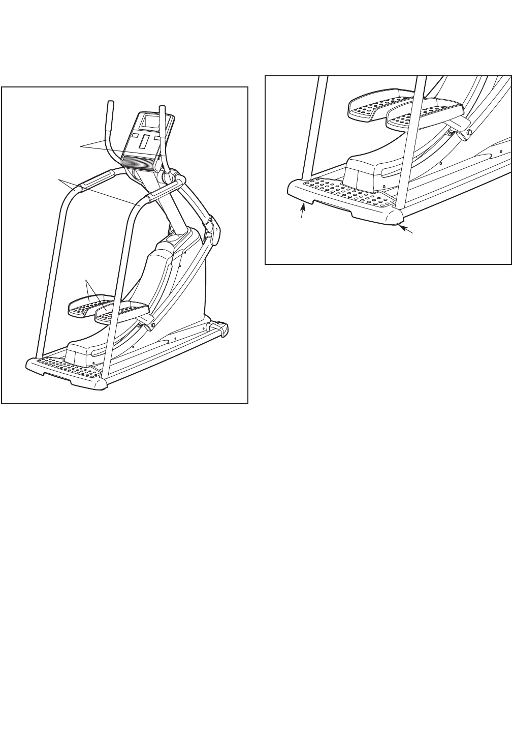
HOW TO EXERCISE ON THE ELLIPTICAL STRIDER
To mount the elliptical strider, hold the handlebars or
the handrails and step onto the pedals. Push the ped-
als until they begin to move forward and backward
with a continuous motion.
To dismount the elliptical strider, wait until the pedals
come to a complete stop. When the pedals are sta-
tionary, hold the handlebars or the handrails and step
off the pedals.
HOW TO LEVEL THE ELLIPTICAL STRIDER
If the elliptical strider rocks slightly on your floor during
use, turn one or both of the leveling feet beneath the
rear of the frame until the rocking motion is eliminated.
Leveling
Foot
Leveling
Foot
Handlebars
Handrails
Pedals
14
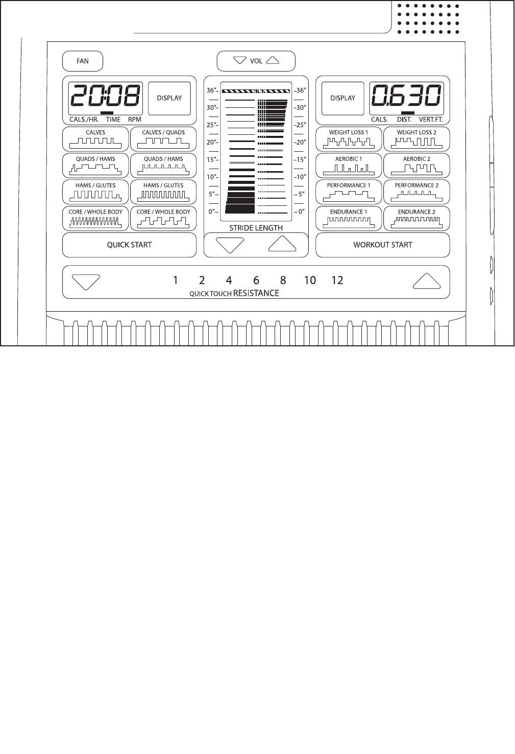
FEATURES OF THE CONSOLE
The advanced console offers an array of features
designed to make your workouts more effective and
enjoyable. When you use the quick start mode of the
console, you can change the resistance of the pedals
or set a target stride length with the touch of a button.
As you exercise, the console will provide continuous
exercise feedback. You can even measure your heart
rate using the handgrip pulse sensor or the included
chest pulse sensor.
The console offers sixteen preset workouts. Each
workout automatically changes the resistance of the
pedals and prompts you to maintain a target stride
length as it guides you through an effective workout.
The console features the iFit Interactive Workout
System, which enables the console to accept iFit
cards containing workouts designed to help you
achieve specific fitness goals. For example, lose
unwanted pounds with the 8-week Weight Loss work-
out. iFit workouts control the resistance of the pedals
while the voice of a personal trainer coaches you
through your workouts. iFit cards are available sepa-
rately. To purchase iFit cards, go to www.iFit.com
or see the front cover of this manual. iFit cards are
also available at select stores.
You can even connect your MP3 player or CD player
to the consoleʼs sound system and listen to your
favorite workout music or audio books while you exer-
cise.
To activate the console, see page 15. To turn off
the console, see page 15. To use the quick start
mode, see page 15. To use a preset workout, see
page 17. To use an iFit workout, see page 18. To
use the sound system, see page 18. To use the
maintenance mode, see page 19.
CONSOLE DIAGRAM
15
HOW TO ACTIVATE THE CONSOLE
The included AC power adapter must be used to oper-
ate the elliptical strider. See HOW TO PLUG IN THE
AC POWER ADAPTER on page 12. When the AC
power adapter is plugged in, the displays will light and
the console will be ready for use.
IMPORTANT: If the console has been exposed to
cold temperatures, allow it to warm to room tem-
perature before activating the console. Otherwise,
you may damage the console displays or other
electronic components.
HOW TO TURN OFF THE CONSOLE
If the pedals are not moved for a short period of time,
the console will enter an idle mode and a screen
saver will appear in the center display. Unplug the AC
power adapter when the elliptical strider is not in use.
HOW TO USE THE QUICK START MODE
The quick start mode allows you to start exercising,
adjust the resistance of the pedals manually, and set a
target stride length manually.
1. Press the QUICK START button or begin strid-
ing to activate the console.
See HOW TO ACTIVATE THE CONSOLE above.
2. Select the quick start mode.
When you activate the con-
sole, the quick start mode
will be selected. If you have
selected a workout, rese-
lect the quick start mode by
pressing any of the workout
buttons repeatedly until zeros appear in the left
and right displays.
3. Change the resistance of the pedals as
desired.
As you stride, change the resistance of the pedals
by pressing one of the numbered QUICKTOUCH
RESISTANCE buttons or by pressing the QUICK-
TOUCH RESISTANCE increase and decrease but-
tons. Note: After you press a QUICKTOUCH
RESISTANCE button, it will take a moment for the
pedals to reach the selected resistance level.
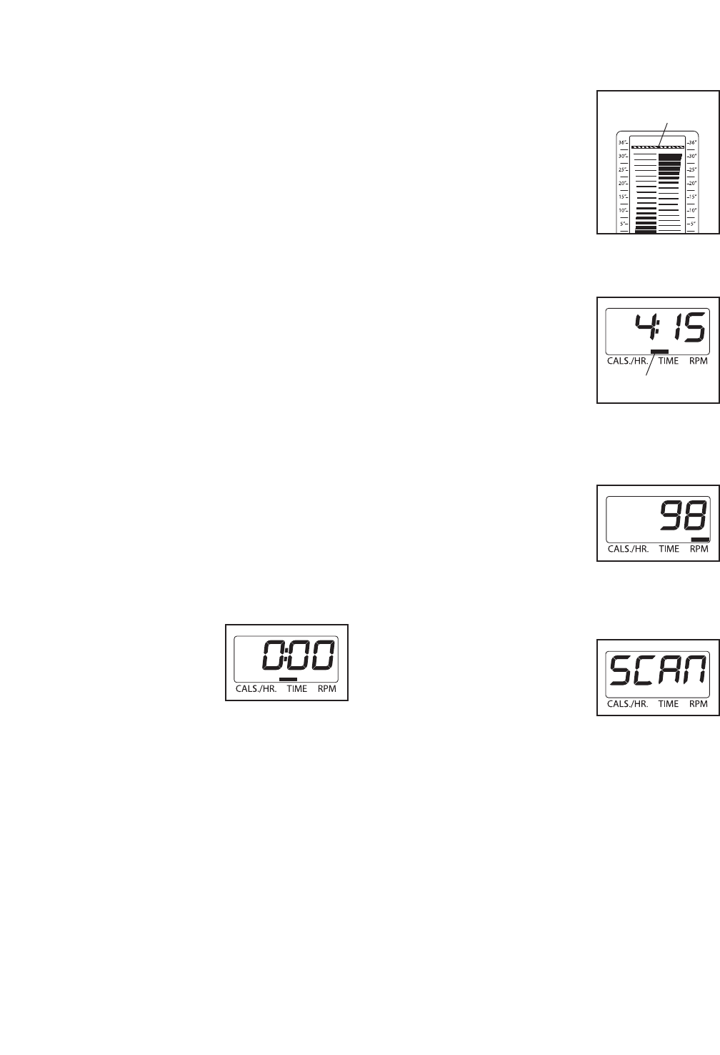
4. Set a target stride length as desired.
The stride length meter in the center display
allows you to set a target stride length.
To set a target stride length,
press the STRIDE LENGTH
increase and decrease but-
tons below the stride length
meter repeatedly until the
target bar appears next to
the desired stride length.
Note: Stride length is mea-
sured in inches.
5. Follow your progress with the displays.
Left display–This display
will show the approximate
number of calories you are
burning per hour, the
elapsed time, and your
striding pace in revolutions
per minute (rpm), for a few
seconds each, in a repeat-
ing scan cycle. An indicator will show which infor-
mation is currently displayed.
To select the approximate
number of calories you are
burning per hour, the
elapsed time, or your strid-
ing pace for continuous dis-
play, press the left Display
button repeatedly until an indicator appears above
the information you are interested in viewing.
To reselect the scan cycle,
press the left Display button
repeatedly until the word
SCAN appears in the left
display.
Note: When you select a workout, the display will
show the time remaining in the workout instead of
the elapsed time.
Target Bar
Indicator
16
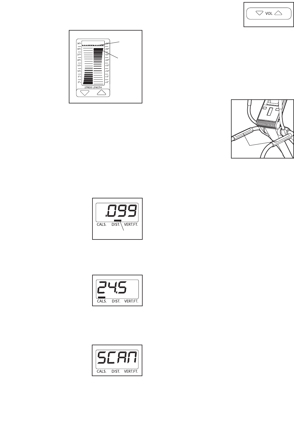
Center display–This display shows the stride
length meter. The stride length meter compares
your actual stride length to the target stride length.
The target bar in
the stride length
meter indicates the
target stride
length. The pedal
blocks track the
actual movement
of the pedals while
you exercise.
As you exercise, keep your stride length near the
target stride length by striding so that the pedal
blocks move back and forth between the bottom of
the display and the target bar.
The center display will also show the resistance
level of the pedals for a few seconds each time the
resistance level changes. In addition, the center dis-
play will show your heart rate when you use the
handgrip pulse sensor (see step 6 at the right) or
the included chest pulse sensor (see page 11).
Right display–This display
will show the approximate
number of calories you
have burned, the distance
(total number of miles) you
have stridden, and the dis-
tance (vertical feet) you
have climbed, for a few sec-
onds each, in a repeating scan cycle. An indicator
will show which information is currently displayed.
To select the approximate
number of calories you
have burned, the distance
you have stridden, or the
distance you have climbed
for continuous display,
press the right Display button repeatedly until an
indicator appears above the information you are
interested in viewing.
To reselect the scan cycle,
press the right Display but-
ton repeatedly until the
word SCAN appears in the
right display.
To adjust the volume level
of the console, press the
VOL increase and decrease
buttons.
6. Measure your heart rate if desired.
To use the included chest pulse sensor, see page
11. To use the handgrip pulse sensor, follow the
instructions below. Note: If you wear the chest
pulse sensor and hold the handgrip pulse sen-
sor at the same time, the console will not dis-
play your heart rate accurately.
If there are sheets of
clear plastic on the
metal contacts on the
handgrip pulse sen-
sor, remove the plas-
tic. In addition, make
sure that your hands
are clean. To measure
your heart rate, hold
the handgrip pulse
sensor with your palms resting against the metal
contacts. Avoid moving your hands or gripping
the contacts tightly.
When you hold the handgrip pulse sensor, the
word PULSE and a set of flashing dashes will
appear in the center display. Then, when your
pulse is detected, your heart rate will be shown in
the center display. For the most accurate heart
rate reading, hold the contacts for at least 15 sec-
onds.
If your heart rate is not shown, make sure that
your hands are positioned as described. Be care-
ful not to move your hands excessively or to
squeeze the metal contacts tightly. For optimal
performance, clean the metal contacts using a soft
cloth; never use alcohol, abrasives, or chemi-
cals to clean the contacts.
7. Turn on the fan if desired.
The fan has high and low speed settings. Press
the FAN button repeatedly to select a fan speed or
to turn off the fan. Note: If the pedals do not move
for about thirty seconds, the fan will turn off auto-
matically.
8. When you are finished using the elliptical
strider, the console will automatically enter an
idle mode.
See HOW TO TURN OFF THE CONSOLE on
page 15.
Contacts
Target
Bar
Pedal
Block
Indicator
17
HOW TO USE A PRESET WORKOUT
Apreset workout automatically changes the resistance
of the pedals and prompts you to maintain a target
stride length.
1. Press any button or begin striding to activate
the console.
See HOW TO ACTIVATE THE CONSOLE on page
15.
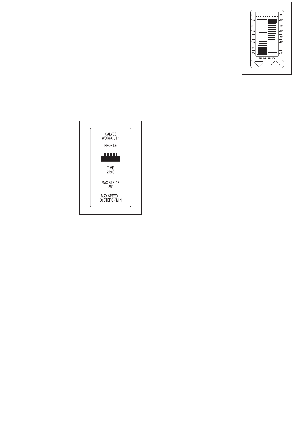
2. Select a preset workout.
To select a preset workout, press the workout but-
ton with the desired name and profile.
The following informa-
tion will appear in the
center display:
• The name of the
workout
• A profile of the target
stride lengths
• The duration of the
workout
• The maximum stride
length
• The maximum
speed (in steps per
minute)
3. Press the WORKOUT START button or begin
striding to start the workout.
Each preset workout is divided into 25, 30, 45, or
60 one-minute segments. One resistance level
and one stride length is programmed for each seg-
ment. Note: The same resistance level and/or
stride length may be programmed for consecutive
segments.
During the workout, the workout profile will show
your progress (see the drawing above). The flash-
ing column of the profile represents the current
segment of the workout. The height of the flashing
column indicates the stride length for the current
segment. At the end of each segment of the work-
out, a series of tones will sound and the next seg-
ment of the profile will begin to flash. If a different
resistance level is programmed for the next seg-
ment, the resistance level of the pedals will then
change.
As you exercise, keep your
stride length near the target
stride length for the current
segment, which is shown in
the stride length meter in
the center display. IMPOR-
TANT: The target stride
length settings are
intended only to provide
motivation. Your actual
stride length may be
shorter or longer than the
target stride length. Make sure to stride at a
length that is comfortable for you.
If the stride length for the current segment is too
long or too short, you can manually override the
setting by pressing the STRIDE LENGTH buttons.
However, when the current segment ends, the
stride length meter will automatically adjust to the
target stride length for the next segment.
If the resistance level for the current segment is
too high or too low, you can manually override the
setting by pressing the QUICKTOUCH RESIS-
TANCE buttons. However, when the current seg-
ment ends, the pedals will automatically adjust to
the resistance level for the next segment.
The workout will continue in this way until the last
segment of the profile flashes. To stop the workout
at any time, stop striding. To resume the workout,
simply resume striding or press the WORKOUT
START BUTTON.
4. Follow your progress with the displays.
See step 5 on page 15.
5. Measure your heart rate if desired.
See step 6 on page 16.
6. Turn on the fan if desired.
See step 7 on page 16.
7. When you are finished using the elliptical
strider, the console will automatically enter an
idle mode.
See HOW TO TURN OFF THE CONSOLE on
page 15.
18
HOW TO USE AN IFIT WORKOUT
iFit cards are available separately. To purchase iFit
cards, go to www.iFit.com or see the front cover of this
manual. iFit cards are also available at select stores.
1. Press any button or begin striding to activate
the console.
See HOW TO ACTIVATE THE CONSOLE on page
15.
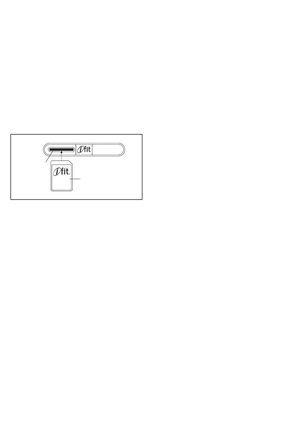
2. Insert an iFit card and select a workout.
To use an iFit workout, insert an iFit card into the
iFit slot, which is located on the right side of the
console. The iFit card should slide easily into the
slot. If it does not, turn the iFit card and try again.
iFit workouts function in the same way as preset
workouts. To use an iFit workout, see steps 3 to 7
on page 17.
Some iFit cards contain more than one workout.
To select a workout, press the STRIDE LENGTH
increase and decrease buttons.
During an iFit workout, press the STRIDE
LENGTH increase and decrease buttons to adjust
the volume level for the voice of the personal
trainer.
3. When you are finished exercising, remove the
iFit card.
Remove the iFit card when you are finished exer-
cising. Store the iFit card in a secure place.
HOW TO USE THE SOUND SYSTEM
To play music or audio books through the consoleʼs
sound system while you exercise, plug the included
audio cable into the MP3 jack on the right side of the
console and into a jack on your MP3 player or CD
player; make sure that the audio cable is fully
plugged in.
Next, press the play button on your MP3 player or CD
player. Press the VOL increase and decrease buttons
on the console to adjust the volume level or use the
volume control on your MP3 player or CD player.
You can use your own headphones with the console
or with an iFit workout (see HOW TO USE AN IFIT
WORKOUT at the left). To use your headphones, plug
your headphones cable into the headphones jack on
the right side of the console; make sure that the
headphones cable is fully plugged in.
iFit Slot
iFit Card

19
HOW TO USE THE MAINTENANCE MODE
The console features a maintenance mode that allows
you to access usage information and to view and
change console settings.
1. Press any button or begin striding to activate
the console.
See HOW TO ACTIVATE THE CONSOLE on page
15.
2. Select the maintenance mode.
Press and hold down the FAN button for a few
seconds to select the maintenance mode.
When the maintenance mode is selected, usage
information for the elliptical strider will appear in
the center display.
3. View and reset the usage information if
desired.
The first section of the center display will show the
total number of hours that the elliptical strider has
been used, the total number of vertical feet that
the pedals have climbed, and the total distance
that the pedals have been moved.
To reset the usage information to zero, press and
hold down the Resistance increase and decrease
buttons simultaneously for several seconds.
4. Adjust the contrast level of the console
displays if desired.
To adjust the contrast level of the console dis-
plays, press the STRIDE LENGTH increase and
decrease buttons until the console displays show
the desired contrast.
5. Exit the maintenance mode.
Press the QUICK START or the WORKOUT
START button to exit the maintenance mode.

20
MAINTENANCE AND TROUBLESHOOTING
If you have questions about maintenance or trou-
bleshooting, see the front cover of this manual.
Inspect and tighten all parts of the elliptical strider regu-
larly. Replace any worn parts immediately.
To clean the elliptical strider, use a damp cloth and a
small amount of mild soap. Make sure to regularly
clean the rollers and the track frame on which the
rollers ride. IMPORTANT: To avoid damage to the
console, keep liquids away from the console and
keep the console out of direct sunlight.
HOW TO LEVEL THE ELLIPTICAL STRIDER
If the elliptical strider rocks slightly on your floor during
use, see HOW TO LEVEL THE ELLIPTICAL
STRIDER on page 13.
21
These guidelines will help you to plan your exercise
program. For detailed exercise information, obtain a
reputable book or consult your physician. Remember,
proper nutrition and adequate rest are essential for
successful results.
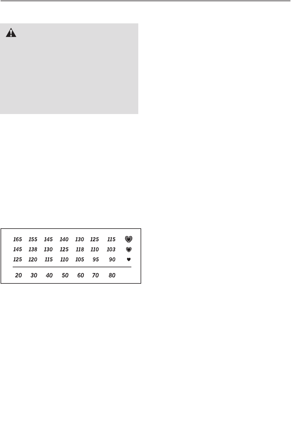
EXERCISE INTENSITY
Whether your goal is to burn fat or to strengthen your
cardiovascular system, exercising at the proper inten-
sity is the key to achieving results. You can use your
heart rate as a guide to find the proper intensity level.
The chart below shows recommended heart rates for
fat burning and aerobic exercise.
To find the proper intensity level, find your age at the
bottom of the chart (ages are rounded off to the near-
est ten years). The three numbers listed above your
age define your “training zone.” The lowest number is
the heart rate for fat burning, the middle number is the
heart rate for maximum fat burning, and the highest
number is the heart rate for aerobic exercise.
Burning Fat—To burn fat effectively, you must exer-
cise at a low intensity level for a sustained period of
time. During the first few minutes of exercise, your
body uses carbohydrate calories for energy. Only after
the first few minutes of exercise does your body begin
to use stored fat calories for energy. If your goal is to
burn fat, adjust the intensity of your exercise until your
heart rate is near the lowest number in your training
zone. For maximum fat burning, exercise with your
heart rate near the middle number in your training
zone.
Aerobic Exercise—If your goal is to strengthen your
cardiovascular system, you must perform aerobic
exercise, which is activity that requires large amounts
of oxygen for prolonged periods of time. For aerobic
exercise, adjust the intensity of your exercise until
your heart rate is near the highest number in your
training zone.
WORKOUT GUIDELINES
Warming Up—Start with 5 to 10 minutes of stretching
and light exercise. A warm-up increases your body
temperature, heart rate, and circulation in preparation
for exercise.
Training Zone Exercise—Exercise for 20 to 30 min-
utes with your heart rate in your training zone. (During
the first few weeks of your exercise program, do not
keep your heart rate in your training zone for longer
than 20 minutes.) Breathe regularly and deeply as you
exercise–never hold your breath.
Cooling Down—Finish with 5 to 10 minutes of
stretching. Stretching increases the flexibility of your
muscles and helps to prevent post-exercise problems.
EXERCISE FREQUENCY
To maintain or improve your condition, complete three
workouts each week, with at least one day of rest
between workouts. After a few months of regular exer-
cise, you may complete up to five workouts each
week, if desired. Remember, the key to success is to
make exercise a regular and enjoyable part of your
everyday life.
EXERCISE GUIDELINES
WARNING: Before beginning
this or any exercise program, consult your
physician. This is especially important for
persons over age 35 or persons with pre-
existing health problems.
The pulse sensor is not a medical device.
Various factors may affect the accuracy of
heart rate readings. The pulse sensor is
intended only as an exercise aid in determin-
ing heart rate trends in general.
22
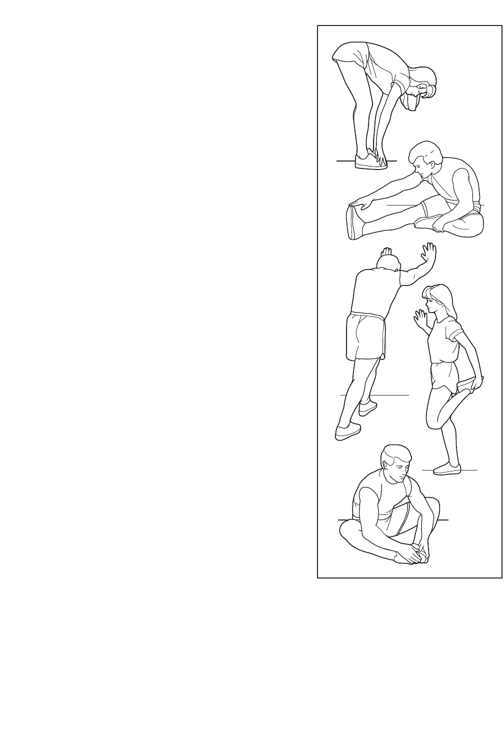
SUGGESTED STRETCHES
The correct form for several basic stretches is shown at the right.
Move slowly as you stretch—never bounce.
1. Toe Touch Stretch
Stand with your knees bent slightly and slowly bend forward from
your hips. Allow your back and shoulders to relax as you reach
down toward your toes as far as possible. Hold for 15 counts,
then relax. Repeat 3 times. Stretches: Hamstrings, back of knees
and back.
2. Hamstring Stretch
Sit with one leg extended. Bring the sole of the opposite foot
toward you and rest it against the inner thigh of your extended
leg. Reach toward your toes as far as possible. Hold for 15
counts, then relax. Repeat 3 times for each leg. Stretches:
Hamstrings, lower back and groin.
3. Calf/Achilles Stretch
With one leg in front of the other, reach forward and place your
hands against a wall. Keep your back leg straight and your back
foot flat on the floor. Bend your front leg, lean forward and move
your hips toward the wall. Hold for 15 counts, then relax. Repeat 3
times for each leg. To cause further stretching of the achilles ten-
dons, bend your back leg as well. Stretches: Calves, achilles ten-
dons and ankles.
4. Quadriceps Stretch
With one hand against a wall for balance, reach back and grasp
one foot with your other hand. Bring your heel as close to your
buttocks as possible. Hold for 15 counts, then relax. Repeat 3
times for each leg. Stretches: Quadriceps and hip muscles.
5. Inner Thigh Stretch
Sit with the soles of your feet together and your knees outward.
Pull your feet toward your groin area as far as possible. Hold for
15 counts, then relax. Repeat 3 times. Stretches: Quadriceps and
hip muscles.
1
2
3
4
5

23
PART LIST—Model No. NTSR01909.1 R1109A
11Frame
22 Track
32Shield Bracket
41Console
51Shield Cap
61Right Shield
71Left Shield
81Right Frame Cover
91Left Frame Cover
10 1 Front Shield
11 1 Track Shield
12 1 Rear Frame Cover
13 1 Rear Shield
14 1 Right Upper Cover
15 1 Right Lower Cover
16 1 Left Upper Cover
17 1 Left Lower Cover
18 1 Accessory Tray
19 1 Drive Belt
20 1 Right Handlebar
21 1 Left Handlebar
22 2 Right Link Cover
23 2 Left Link Cover
24 1 Right Pedal Arm
25 1 Left Pedal Arm
26 1 Upright
27 2 Handgrip
28 2 Pedal
29 2 Pedal Insert
30 2 Pulse Sensor
31 2 Sensor Back
32 1 Left Cable Arm
33 1 Right Cable Arm
34 2 Upper Cable
35 1 Lower Cable
36 2 Pedal Leg Cap
37 2 Roller Spacer
38 2 Roller
39 1 Flywheel
40 8 Cable Bushing
41 1 Magnet Bracket
42 1 Flywheel Hub
43 2 Flywheel Bearing
44 1 Resistance Motor
45 1 Motor Disc
46 1 Tension Bracket
47 1 Tension Spring
48 1 Tension Pulley
49 1 Tension Bushing
50 1 Resistance Bar
51 1 Magnet Ring
52 2 Hard Pulley
53 1 Drive Belt Pulley
54 2 Cable Spool
55 1 Spool Hub
56 2 Spool Bearing
57 1 Magnet Ring Sensor
58 2 Frame Bracket
59 1 Spool Axle
60 3 Soft Pulley
61 1 Hub Key
62 2 Foot
63 2 Leveling Foot
64 1 Bumper
65 1 Wiring Bracket
66 2 Spool Cover
67 2 Sensor Bracket
68 1 Cable Pulley Bracket
69 1 Right Handrail
70 1 Left Handrail
71 2 Handrail Flange
72 2 Handrail Spacer
73 4 Handlebar Bearing
74 4 Wheel Spacer
75 2 Wheel
76 1 AC Power Adapter
77 1 Wire Harness
78 2 Pulse Wire
79 2 Sensor Wire
80 3 1/2" Nut
81 1 Power Cable
82 1 Ground Wire
83 4 Wheel Bearing
84 2 Pulley Bearing
85 1 Pedal Sensor
86 37 #8 x 3/4" Screw
87 4 Link Bearing
88 1 5/16" x 1" Bolt
89 2 Link Axle
90 3 5/16" Locknut
91 6 1/2" Snap Ring
92 2 1 1/8" Snap Ring
93 3 #8 x 1/2" Flange Screw
94 3 #8 x 8mm Flange Screw
95 41 #8 x 1/2" Screw
96 4 #3 x 5mm Screw
97 15 5/16" x 3/4" Screw
98 4 #6 x 9.5mm Bolt
99 2 3/8" x 1" Screw
100 5 5/16" x 1/2" Screw
Key No. Qty. Description Key No. Qty. Description

24
101 2 1/4" x 9.5mm Screw
102 1 M8 x 86mm Bolt
103 1 3/8" x 80mm Bolt
104 2 5/16" x 63.5mm Bolt
105 2 1/4" x 22mm Screw
106 1 #10 x 6.5mm Screw
107 10 M6 x 12mm Screw
108 10 #8 x 10mm Screw
109 1 3/8" x 41mm Bolt
110 2 1/2" x 70mm Screw
111 4 1/4" x 3/4" Screw
112 4 3/8" Locknut
113 1 M8 Locknut
114 4 #6 Locknut
115 6 Clip
116 2 M10 Flat Washer
117 2 1" Snap Ring
118 1 3/4" Snap Ring
119 1 #6 x 10mm Screw
120 4 3/8" x 3/4" Screw
121 4 3/4" Washer
122 4 3/8" x 1" Patch Screw
123 2 3/8" x 3/4" Patch Screw
124 2 3/8" x 3" Screw
125 1 #8 x 35mm Screw
126 8 #8 x 1" Tek Screw
127 4 1/4" x 3/4" Patch Screw
128 2 M10 Split Washer
*–Audio Cable
*–Userʼs Manual
*–Assembly Tool
Note: Specifications are subject to change without notice. For information about ordering replacement parts, see
the back cover of this manual. *These parts are not illustrated.
Key No. Qty. Description Key No. Qty. Description
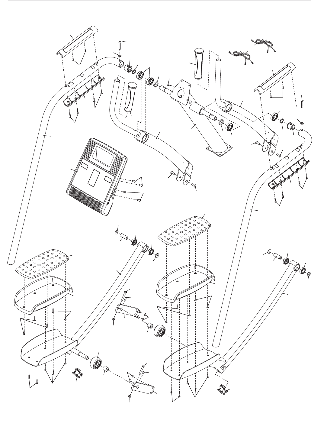
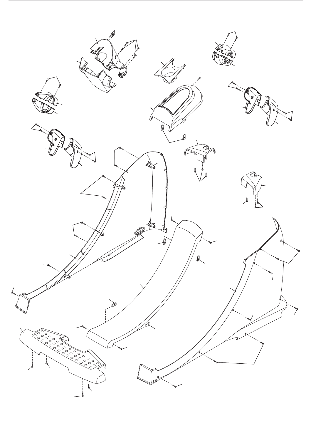
25
EXPLODED DRAWING A—NTSR01909.1 R1109A
4
21
20
24
25
28
28
29
29
32
33
37
38
37
38
79
87
87
87
87
89
89
26
27
27
30
30
31
31
36 36
69
70 71
71
72
72 73
73
73
86
86
86
86
86
123
123
120
120
120
120
127
127
108
108
108
108
107
107
107
107
104
105
90
91
104
105
90
91
96
96
117
117
128
128
121
121
121
121
26
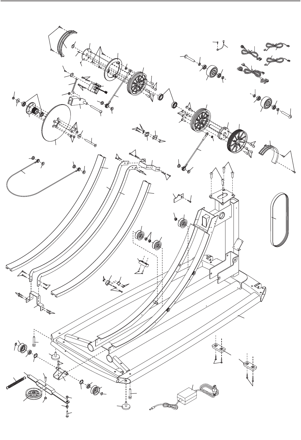
EXPLODED DRAWING B—NTSR01909.1 R1109A
1
2
3
3
19
34
34
35 40
40
40
40
40 40
40
40
48
46
47
49
52
52
53
54
54
59
55
61
62
63
63
65
66
66
67
74
74
74
74
75
75
76
77
81
82 78
83
83
83
83
39
41
42
43 95
44
45
50
51
56
57
58
58
68
84
84
85
110
110
95
97
97
112
97
97
97
97
112
95
106
118
95
119
95
112
103
95
98
100
100
102
95 95
95
95
94
122
122
64
93
113
95
95
95
95
111
111
91
91
109
112
90
99
93
99
114
116
116
124
124
92
88
101
92
67
95
114
98
2
80
80
60
60
60
27
EXPLODED DRAWING C—NTSR01909.1 R1109A
6
7
11
13 18
10
12
8
9
14
15
16
17
5
22
22
23
23
86
86
86
86
126
125
126
95
95 95
86
86
86
86
86
86
95
95
86
95
95
86
94 86
86
86
86
86
126
126
115
115
115
94
115
115

Part No. 279095 R1109A Printed in China © 2009 ICON IP, Inc.
ORDERING REPLACEMENT PARTS
To order replacement parts, please see the front cover of this manual. To help us assist you, be prepared to
provide the following information when contacting us:
• the model number and serial number of the product (see the front cover of this manual)
• the name of the product (see the front cover of this manual)
• the key number and description of the replacement part(s) (see the PART LIST and the EXPLODED
DRAWING near the end of this manual)
ICON Health & Fitness, Inc. (ICON) warrants this product to be free from defects in workmanship and
material, under normal use and service conditions. The frame is warranted for a lifetime. Parts are war-
ranted for seven (7) years from the date of purchase. Labor is warranted for one (1) year from the date
of purchase.
This warranty extends only to the original purchaser. ICONʼs obligation under this warranty is limited to
repairing or replacing, at ICONʼs option, the product through one of its authorized service centers. All
repairs for which warranty claims are made must be preauthorized by ICON. If the product is shipped to
a service center, freight charges to and from the service center will be the customerʼs responsibility. For
replacement parts shipped while the product is under warranty, the customer will be responsible for a min-
imal handling charge. For in-home service, the customer will be responsible for a minimal trip charge. This
warranty does not extend to any damage to a product caused by or attributable to freight damage, abuse,
misuse, improper or abnormal usage, or repairs not provided by an ICON authorized service center; to
products used for commercial or rental purposes or as store display models; or to products transported
or purchased outside the US. No other warranty beyond that specifically set forth above is authorized by
ICON.
ICON is not responsible or liable for indirect, special, or consequential damages arising out of or in con-
nection with the use or performance of the product; damages with respect to any economic loss, loss of
property, loss of revenues or profits, loss of enjoyment or use, or costs of removal or installation; or other
consequential damages of whatsoever nature. Some states do not allow the exclusion or limitation of inci-
dental or consequential damages. Accordingly, the above limitation may not apply to you.
The warranty extended hereunder is in lieu of any and all other warranties, and any implied warranties of
merchantability or fitness for a particular purpose are limited in their scope and duration to the terms set
forth herein. Some states do not allow limitations on how long an implied warranty lasts. Accordingly, the
above limitation may not apply to you.
This warranty gives you specific legal rights. You may also have other rights that vary from state to state.
ICON Health & Fitness, Inc., 1500 S. 1000 W., Logan, UT 84321-9813
LIMITED WARRANTY
IMPORTANT: You must register this product within 30 days of the purchase date to avoid added
fees for service needed under warranty. Go to www.nordictrackservice.com/registration.
