Nordictrack 831159770 User Manual VERTEX 670 Manuals And Guides L0306331
NORDICTRACK Weight System Manual L0306331 NORDICTRACK Weight System Owner's Manual, NORDICTRACK Weight System installation guides
831.159770 L0306331
User Manual: Nordictrack 831159770 831159770 NORDICTRACK NORDICTRACK VERTEX 670 - Manuals and Guides View the owners manual for your NORDICTRACK NORDICTRACK VERTEX 670 #831159770. Home:Fitness Equipment Parts:Nordictrack Parts:Nordictrack NORDICTRACK VERTEX 670 Manual
Open the PDF directly: View PDF ![]() .
.
Page Count: 35
m r kVer g 670
Model No. 831.159770
Serial No.
The serial number is found in the
location shown below, Write the
serial number in the space above.
Serial Number Decal
QUESTIONS?
As a manufacturer, we are com-
mitted to providing complete
customer satisfaction. If you
have questions, or if there are
missing parts, we will guarantee
complete satisfaction through
direct assistance from our factory.
TO AVOID DELAYS, PLEASE
CALL DIRECT TO OUR TOLL-
FREE CUSTOMER HOT LINE.
The trained technicians on our
customer hot line will provide
immediate assistance, free of
charge.
CUSTOMER HOT LINE:
1-888-825-2588
Mon.-FrL, 6 a.m.-6 p.m. MST
USER'S MANUAL
www.nordictrack.com
new products, prizes,
fitness tips, and much more!
TABLE OF CONTENTS
IMPORTANT PRECAUTIONS ............................................................. 3
BEFORE YOU BEGIN ................................................................... 4
ASSEMBLY. .......................................................................... 5
CABLE DIAGRAM ..................................................................... 21
ADJUSTMENTS ...................................................................... 22
WEIGHT RESISTANCE CHART .......................................................... 24
TROUBLE-SHOOTING AND MAINTENANCE ................................................ 25
EXERCISE GUIDELINES ................................................................ 26
ORDERING REPLACEMENT PARTS ............................................... Back Cover
LIMITED WARRANTY ........................................................... Back Cover
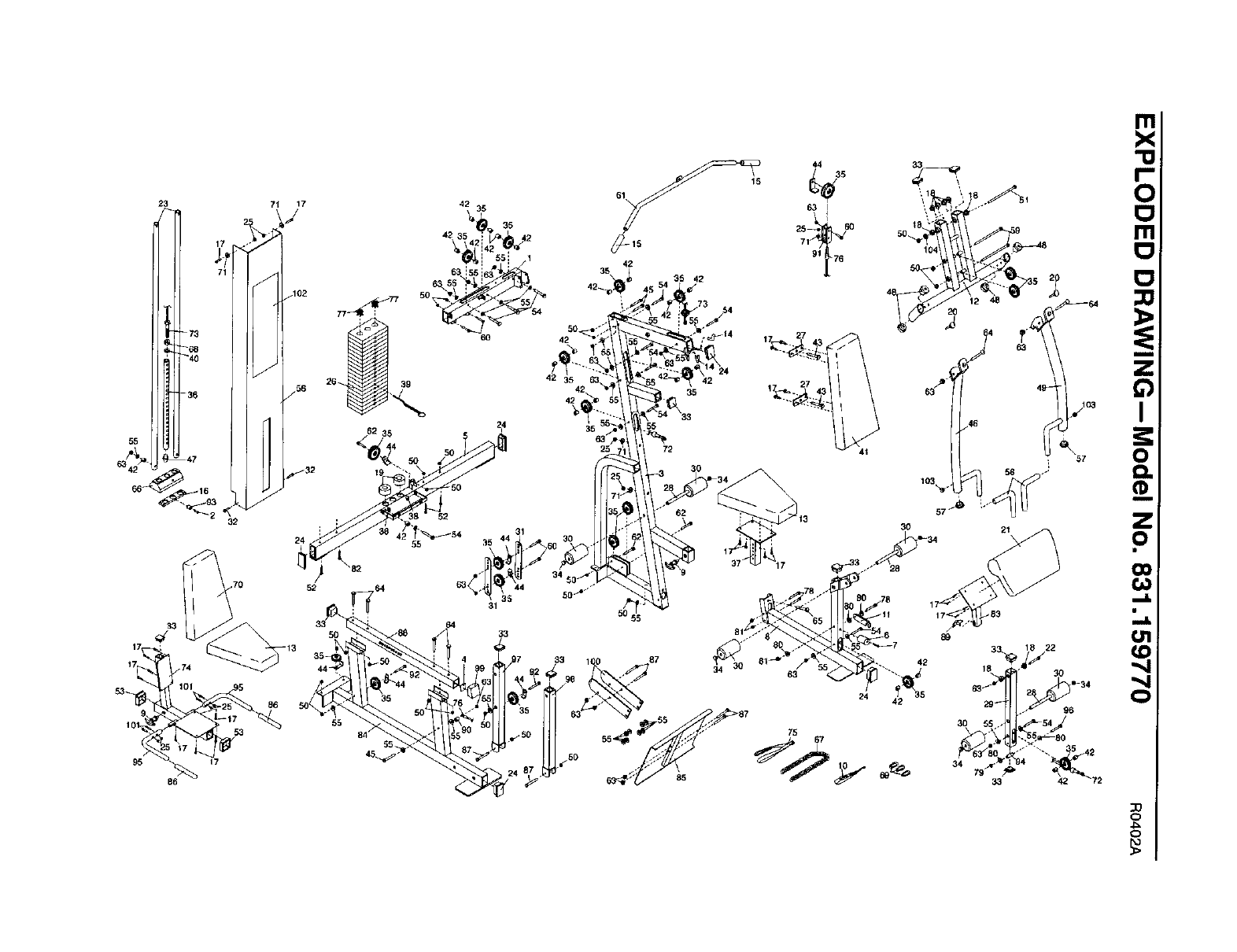
Note: A PART IDENTIFICATION CHART and aPART LIST/EXPLODED DRAWING are attached in the center of
this manual. Remove the PART IDENTIFICATION CHART and PART LIST/EXPLODED DRAWING before begin-
ning assembly.
NordicTrack is a registered trademark of ICON Health &Fitness, Inc.
2
IMPORTANT PRECAUTIONS
WAR NING: To reduce the risk of serious Injury, read the following important precau-
tions before using the weight system.
1. Read all Instructions In this manuel and In
the accompanying literature before using the
weight system. Use the weight system only
as described in this manuel.
12. Never release the press arm, leg lever, Ist
bar, leg press, ab strap, or ankle strap while
weights are raised. The weights will fall with
great force.
2. It is the responsibility of the owner to ensure
that all users of the weight system are ade-
quately informed of all precautions.
3. The weight system Is intended for home use
only. Do not use the weight system in a com-
mercial, rental, or institutional setting.
4. Use the weight system only on a level sur-
face. Cover the floor or carpet beneath the
weight system to protect the floor.
5. Make sure all paris are properly tightened
each time you use the weight system.
Replace any worn parts Immediately.
6. Keep children under the age of 12 and pats
away from the weight system at all times.
7. The weight system is designed to be used by
only one person at a time. The weight sys-
tem is designed to support a maximum user
weight of 250 pounds.
8. Always wear athletic shoes for foot protec-
tion while exercising.
9. Always disconnect the let bar from the
weight system when performing an exercise
that does not require it.
10. Make sure the cables remain on the pulleys
at all times. If the cables bind while you are
exercising, stop immediately and make sure
the cables are on all of the pulleys.
11. Always stand on the foot plate when per-
forming an exercise that could cause the
weight system to tip.
13. Keep hands and feet away from moving
parts.
14. Insert the weight pin fully Into the weight
stack before exercising.
15. If you feel pain or dizziness at any time while
exercising, stop Immediately and cool down.
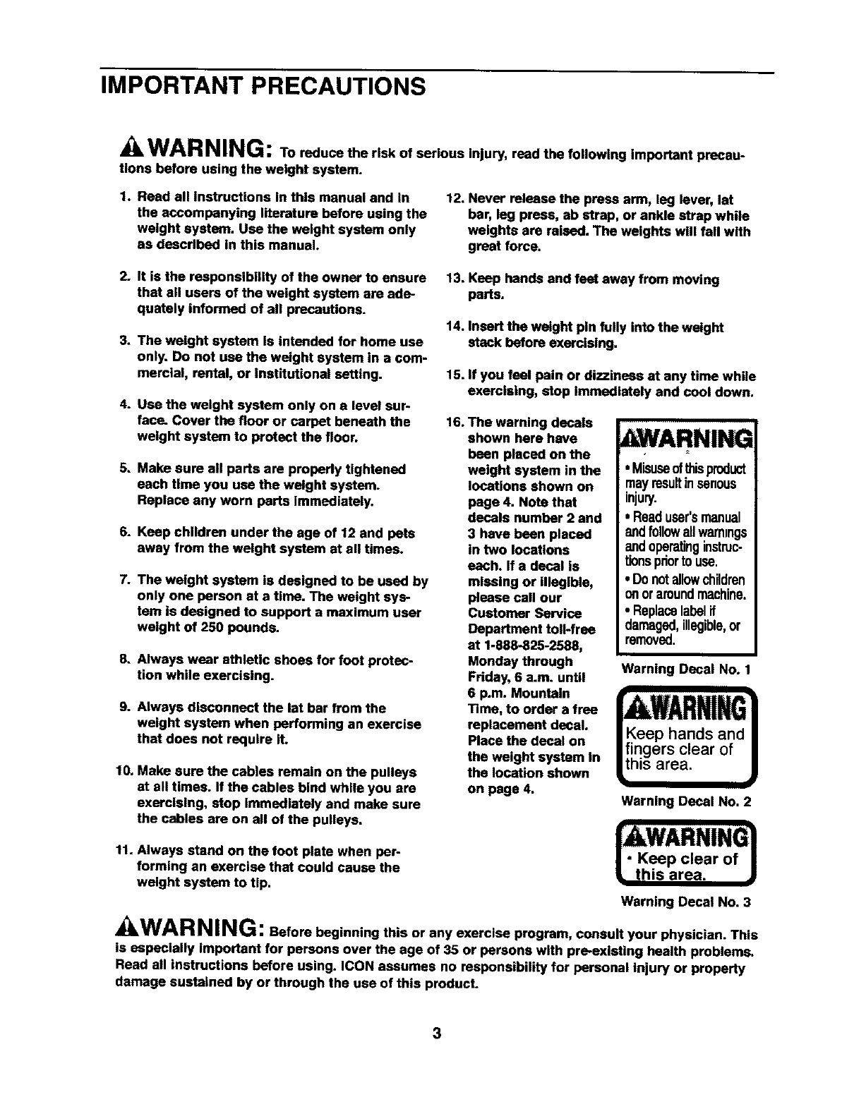
16. The warning decals
shown here have
been placed on the
weight system in the
locations shown on
page 4. Note that
decals number 2 and
3 have been placed
in two locations
each. If a decal is
mleslng or Illegible,
please call our
Customer Service
Department toll-free
at 1-888-825-2588,
Monday through
Friday, 6 a.m. until
6 p.m. Mountain
Time, to order a free
replacement decal.
Place the decal on
the weight system in
the location shown
on page 4.
AWARNING
• Misuseofthisproduct
mayresultinsenous
injury.
• Readuser'smanual
andfollowallwarnings
andoperatinginstruc-
tionspriorto use.
• Donotallowchildren
onoraroundmachine.
• Replacelabelif
damaged,illegible,or
removed.
Warning Decal No.
Warning Decal No. 2
|AWARNING1
J" Keep clear of J
• this area.
Warning Decal No. 3
WAR NING: Before beginning this or any exercise program, consult your physician. This
is especially important for persons over the age of 35 or persons with pre-existing health problems.
Read all instructions before using. ICON assumes no responsibility for personal Injury or property
damage sustained by or through the use of this product.
3
BEFORE YOU BEGIN
Thank you for selecting the versatile NordicTracW
VERTEX 670 weight system. The VERTEX 670 offers
a selection of weight stations designed to develop
every major muscle group of the body, Whether your
goal is to tone your body, build dramatic muscle size
and strength, or improve your cardiovascular system,
the VERTEX 670 will help you to achieve the results
you want.
For your benefit, read this manual carefully before
using the weight system. If you have additionalques-
tions,please call our Customer Service Department
toll-free at 1-888-825-2588, Monday through Friday,
6 a.m. until 6 p.m. Mountain _me (excluding holidays).
To help us assist you, please note the product model
number and serial number before calling. The model
number is 831.159770. The serial number can be
found on a decal attached to the weight system (see
the front cover of this manual).
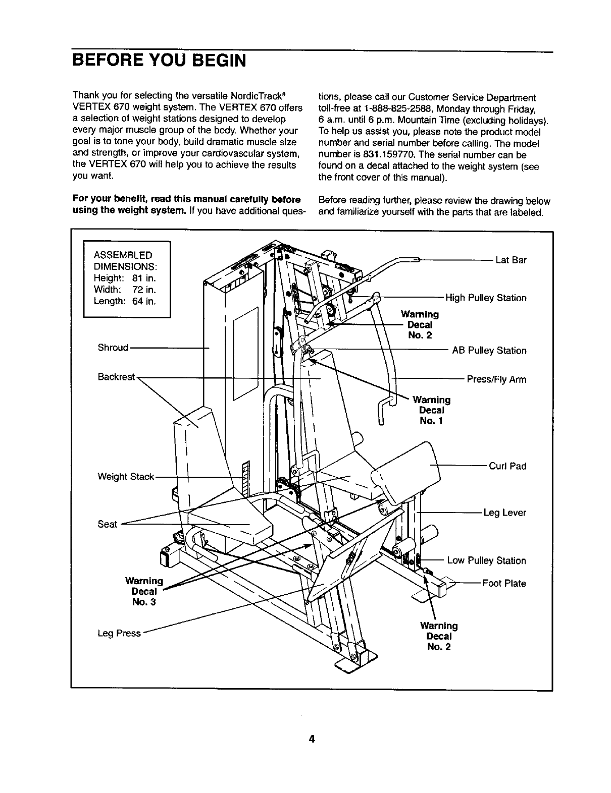
Before readingfurther, please reviewthe drawing below
and familiarize yourselfwith the partsthat are labeled.
ASSEMBLED
DIMENSIONS:
Height: 81 in.
Width: 72 in.
Length: 64 in.
Shroud
Weig
Lat Bar
High Pulley Station
Waming
Decal
No, 2
AB Pulley Station
Press/FlyArm
Decal
No. 1
Curl Pad
Seat Leg Lever
Leg
Warning
Decal
No, 3
Warning
Decal
No. 2
r Station
4
ASSEMBLY
Make Assembly Easier for Yourself
Everythn_ n th s manua is des g_d to
i:iiitttakeSi_ readiiiii_i
iiiiiiiii!:ii ................
Assembly Requires Two Persons
For your convenience and safety, assemble the
weight system withthe help of another person,
Set Aside Enough Time
Due to the many features of the weight system, the
assembly process will require afew hours. By set-
ting aside plenty of time and by deciding to make
the task enjoyable, assembly will go smoothly. You
may want to assemble the weight system over a
couple of evenings.
Select a Location for the Weight System
Because of its weight and size, the weight system
should be assembled in the location where it will be
used. Make sure that there is enough room to walk
around the weight system as you assemble it.
How to Unpack the Box
To make assembly as easy as possible, we have
divided the assembly process into four stages. The
parts needed for each stage are found in individual
bags. Important: Wait until you begin each stage
to open the parts bag for that stage, Place all
parts of the weight system in a cleared area and
remove the packing materials. Do not disposeof
the packingmatedals untilassembly is completed.
Make sure you have the following tools:
•Two adjustable wrenches
•One standard screwdriver
• One phillips screwdriver
• One rubber mallet
•You will also need grease or petroleum jelly, and a
small amount of soapy water.
Note: Assembly will be more convenient if you have
a socket set, a set of open-end or closed-end
wrenches, or a set of ratchet wrenches.
How to Identify Parts
To help you identifythe small parts used in assembly,
we have included aPART IDENTIFICATION CHART
in the center of this manual. Place the chart on the
floor and use it to easily identifyparts during each
assembly step. Note: Some small parts may have
been pre-attached. If a part is not In the parts
bag, check to see if It has been pre-attached.
How to Orient Parts
As you assemble the weight system, orient all parts
exactly as shown in the drawings.
Tightening Parts
Tighten all parts as you assemble them, unless
instructedto do otherwise,
Questions?
If you have questions after reading the assembly
instructions,please call our Customer Service
Department toll-free at 1-888-825-2588 Monday
through Friday, 6 a.m. until 6 p.m. Mountain Time.
The Four Stages of the Assembly Process
Frame Assembly--You will begin by assembling
the base and the uprights that serve as the skele-
ton of the weight system.
Cable Assembly--During this stage you will
attach the cables and pulleysthat connect the
arms and other parts to the weights.
Arm Assembly--During this stage you will
assemble the press arm, leg lever, handles, and
leg press.
Seat Assembly--During this stage you will
assemble the seats, the backrests, the curl pad,
the shroud, and other miscellaneousparts.
5
1,
2.
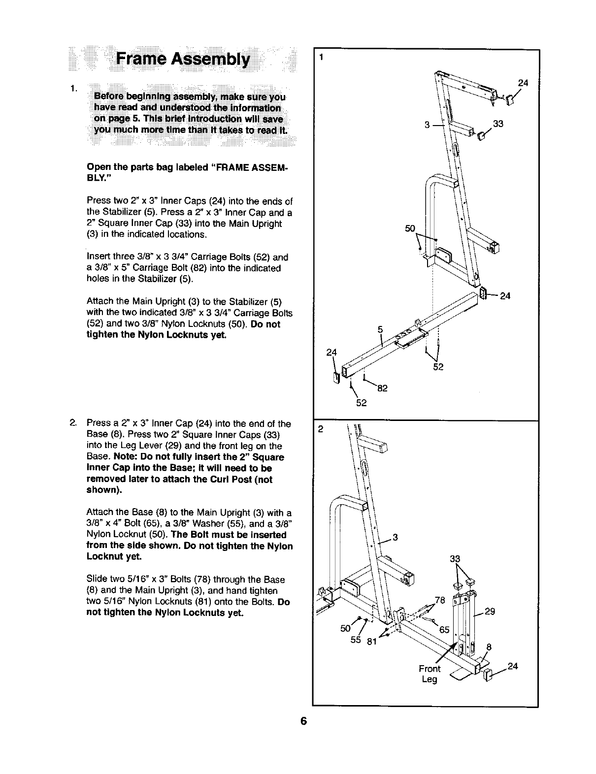
Open the parts bag tabeted "FRAME ASSEM-
BLY."
Press two 2" x 3" Inner Caps (24) into the ends of
the Stabilizer (5). Press a 2" x 3" Inner Cap and a
2" Square Inner Cap (33) into the Main Upright
(3) in the indicated locations.
Insert three 3/8" x 3 3/4" Carriage Bolts (52) and
a 318" x 5" Carriage Bolt (82) into the indicated
holes in the Stabilizer (5).
Attach the Main Upright (3) to the Stabilizer (5)
with the two indicated 3/8" x33/4" Carriage Bolts
(52) and two 3/8" Nylon Locknuts (50). Do not
tighten the Nylon Locknuts yet.
Press a 2" x 3" Inner Cap (24) into the end of the
Base (8). Press two 2" Square Inner Caps (33)
into the Leg Lever (29) and the front leg on the
Base. Note: Do not fully insert the 2" Square
inner Cap into the Base; it will need to be
removed later to attach the Curl Post (not
shown).
Attach the Base (8) to the Main Upright (3) with a
318" x 4" Bolt (65), a 3/8" Washer (55), and a 3/8"
Nylon Locknut (50). The Bolt must be inserted
from the side shown. Do not tighten the Nylon
Locknut yet.
Slide two 5/16" x 3" Bolts (78) through the Base
(8) and the Main Upright (3), and hand tighten
two 5/16" Nylon Locknuts (81) onto the Bolts. Do
not tighten the Nylon Locknuts yet.
24
2
_82
52
55 81
50
52
Front
Leg
33
33
24
8
6
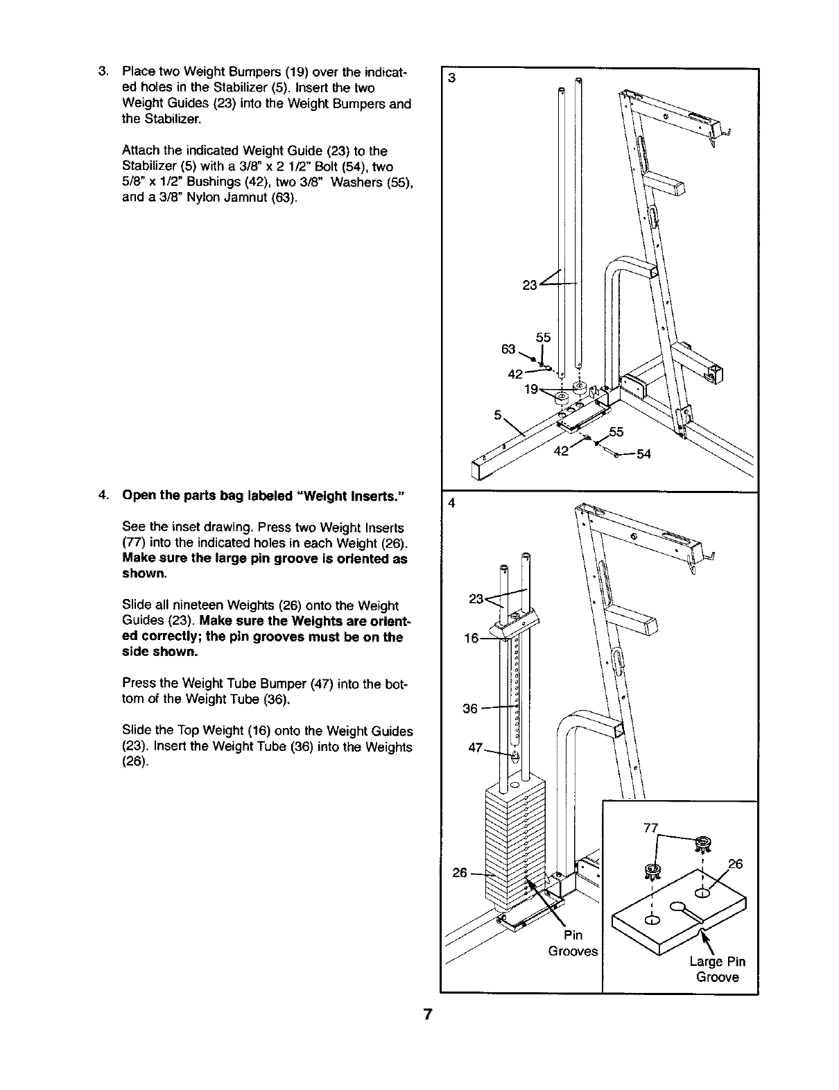
3, Place two Weight Bumpers (19) over the indicat-
ed holes in the Stabilizer (5). Insert the two
Weight Guides (23) into the Weight Bumpers and
the Stabilizer.
Attach the indicated Weight Guide (23) to the
Stabilizer (5) with a 3/8" x 2 1/2" Bolt (54), two
5/8" x 1/2" Bushings (42), two 3/8" Washers (55),
and a 3/8" Nylon Jamnut (63).
4. Open the parts bag labeled "Weight Inserts."
See the inset drawing. Press two Weight Inserts
(77) into the indicated holes in each Weight (26).
Make sure the large pin groove is oriented as
shown,
Slide all nineteen Weights (26) onto the Weight
Guides (23). Make sure the Weights are orient-
ed correctly; the pin grooves must be on the
side shown.
Press the Weight Tube Bumper (47) into the bot-
tom of the Weight Tube (36).
Slide the Top Weight (16) onto the Weight Guides
(23). Insert the Weight Tube (36) into the Weights
(26).
3
23L
55
5".
"_----54
77
Pin
Grooves
7
Large Pin
Groove
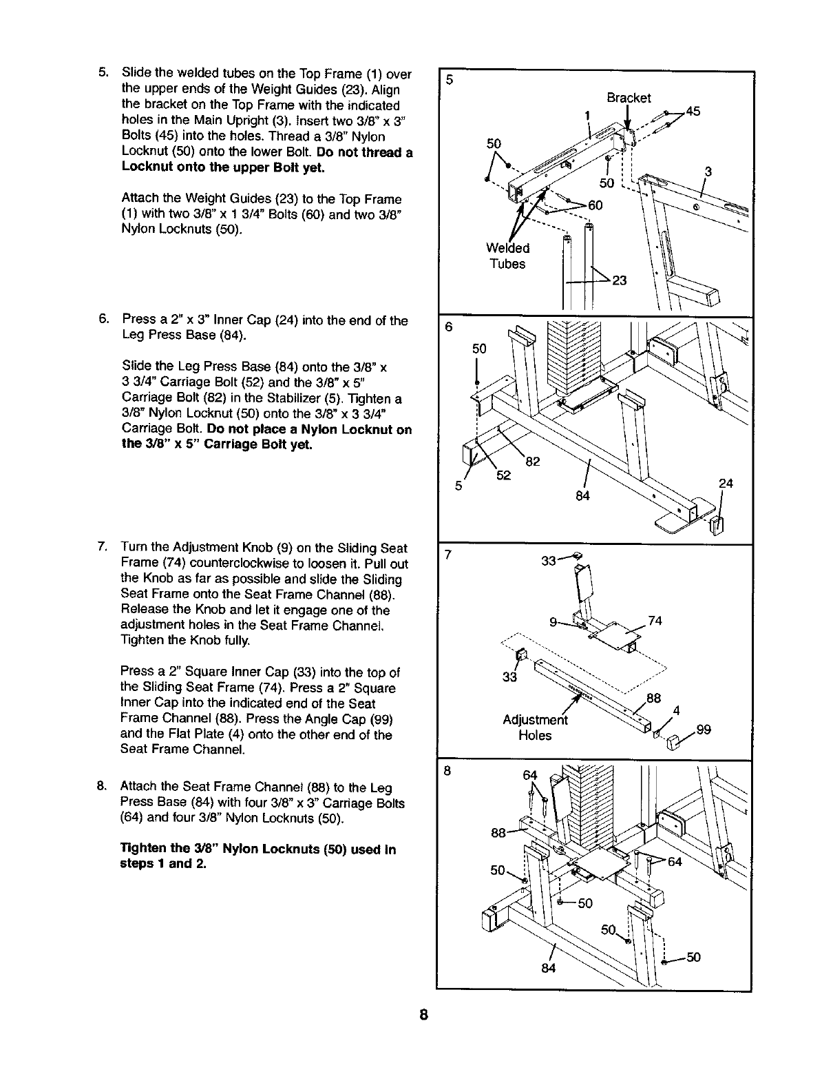
5. Slide the welded tubes on the Top Frame (1) over
the upper ends of the Weight Guides (23). Align
the bracket on the Top Frame with the indicated
holes in the Main Upright (3). Insert two 3/8" x 3"
Bolts (45) into the holes. Thread a 3/8" Nylon
Locknut(50) onto the lower Bolt. Do not thread a
Locknut onto the upper Bolt yet.
Attach the Weight Guides (23) to the Top Frame
(1) with two 3/8" x 1 3/4" Bolts (60) and two 3/8"
Nylon Locknuts (50).
8. Press a 2" x 3" Inner Cap (24) into the end of the
Leg Press Base (84).
Slide the Leg Press Base (84) onto the 3/8" x
33/4" Carriage Bolt (52) and the 3/8" x 5"
Carriage Bolt (82) in the Stabilizer (5). Tighten a
3/8" Nylon Locknut (50) onto the 3/8" x 3 314"
Carriage Bolt. Do not place a Nylon Locknut on
the 3/8" x 5" Carriage Bolt yet.
7, Turn the Adjustment Knob (9) on the Sliding Seat
Frame (74) counterclockwiseto loosen it. Pull out
the Knob as far as possible and slide the Sliding
Seat Frame onto the Seat Frame Channel (88).
Release the Knoband let it engage one of the
adjustment holes in the Seat Frame Channel,
Tighten the Knob fully.
Press a 2" Square Inner Cap (33) into the top of
the Sliding Seat Frame (74). Press a 2" Square
Inner Cap into the indicated end of the Seat
Frame Channel (88). Press the Angle Cap (99)
and the Flat Plate (4) onto the other end of the
Seat Frame Channel.
8. Attach the Seat Frame Channel (88) to the Leg
Press Base (84) with four 3/8" x 3" Carriage Bolts
(64) and four 3/8" Nylon Locknuts (50).
Tighten the 3/8" Nylon Locknuts (50) used In
steps 1 and 2.
5
5
8
50
Welded
Tubes
5O
52
Bracket
1o._7 45
84
33.._
9 74
64
84
8
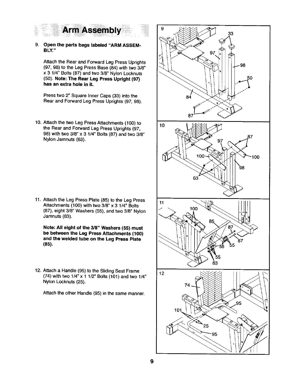
9, Open the parts bags labeled "ARM ASSEM-
BLY."
Attach the Rear and Forward Leg Press Uprights
(97, 98) to the Leg Press Base (84) with two 3/8"
x 3 1/4" Bolts (87) and two 3/8" Nylon Locknuts
(50). Note: The Rear Leg Press Upright (97)
has an extra hole in it.
Press two 2" Square Inner Caps (33) into the
Rear and Forward Leg Press Uprights (97, 98).
10. Attach the two Leg Press Attachments (100) to
the Rear and Forward Leg Press Uprights (97,
98) with two 3/8" x 3 1/4" Bolts (87) and two 3/8"
Nylon Jamnuts (63).
11. Attach the Leg Press Plate (85) to the Leg Press
Attachments (100) with two 318" x 3 114"Bolts
(87), eight 3/8" Washers (55), and two 3/8" Nylon
Jamnuts (63).
Note: All eight of the 3/8" Washers (55) must
be between the Leg Press Attachments (100)
and the welded tube on the Leg Press Plate
(85).
12. Attach a Handle (95) to the Sliding Seat Frame
(74) withtwo 1/4" x 11/2" Bolts (101) and two 1/4"
Nylon Locknuts (25).
Attach the other Handle (95} in the same manner.
9
10
11
I
112
84
87_'"
63
9
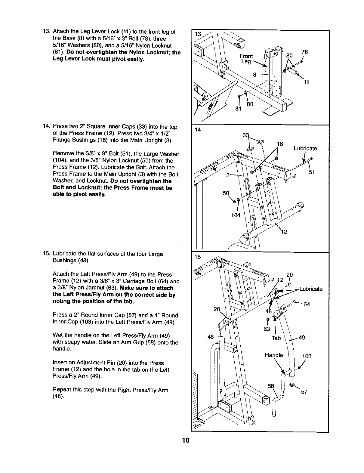
13. Attach the Leg Lever Lock (11) to the front leg of
the Base (8) with a 5/16" x 3" Bolt (78), three
5/16" Washers (80), and a 5116"Nylon Locknut
(81). Do not overtighten the Nylon Locknut; the
Leg Lever Lock must pivot easily.
14. Press two 2" Square Inner Caps (33) into the top
of the Press Frame (12). Press two 314"x 1/2"
Flange Bushings (18) into the Main Upright (3).
Remove the 3/8" x9" Bolt (51), the Large Washer
(104), and the 3/8" Nylon Locknut (50) from the
Press Frame (12). Lubricate the Bolt. Attach the
Press Frame to the Main Upright (3) with the Bolt,
Washer, and Locknut. Do not overtighten the
Bolt and Locknut; the Press Frame must be
able to pivot easily.
15. Lubricate the flat surfaces of the four Large
Bushings(48).
Attach the Left Press/Fly Arm (49) to the Press
Frame (12) with a 3/8" x 3" Carriage Bolt (64) and
a3/8" Nylon Jamnut (63). Make sure to attach
the Left Press/Fly Arm on the correct side by
noting the position of the tab.
Press a 2" Round Inner Cap (57) and a 1" Round
Inner Cap (103) into the Left Press/Fly Arm (49).
Wet the handle on the Left Press/FlyArm (49)
with soapy water, Slide an Arm Grip (58) onto the
handle.
Insert an Adjustment Pin (20) into the Press
Frame (12) and the hole in the tab on the Left
Press/Fly Arm (49).
Repeat this step with the Right Press/Fly Arm
(46).
14
81 80
78
11
18 Lubricate
51
12
2O
103
./
10
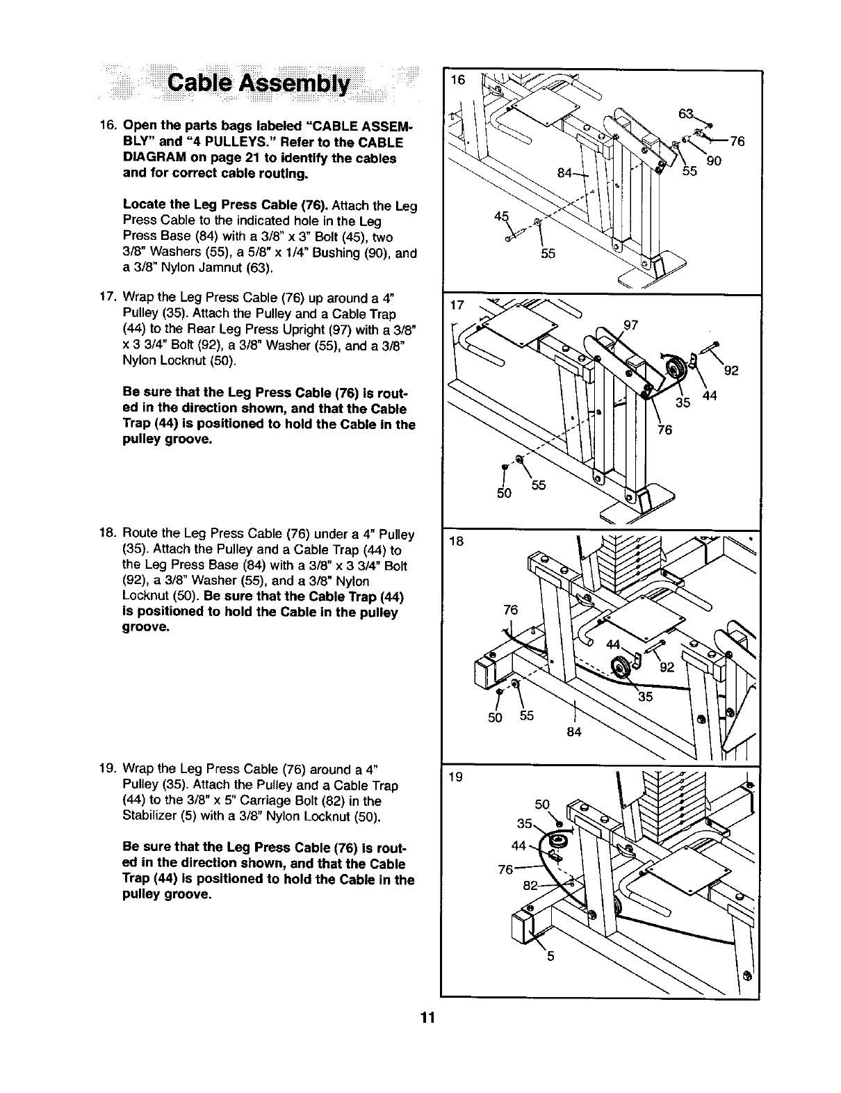
16. Open the parts bags labeled "CABLE ASSEM-
BLY" and "4 PULLEYS." Refer to the CABLE
DIAGRAM on page 21 to identify the cables
and for correct cable routing.
Locate the Leg Press Cable (76). Attachthe Leg
Press Cable to the indicated hole in the Leg
Press Base (84) with a3/8" x 3" Bolt (45), two
3/8" Washers (55), a 5/8" x 1/4" Bushing(90), and
a3/8" Nylon Jamnut (63).
17. Wrap the Leg Press Cable (76) up around a4"
Pulley (35). Attachthe Pulley and aCable Trap
(44) to the Rear Leg Press Upright (97) with a3/8"
x 3 3/4" Bolt (92), a3/8" Washer (55), and a 3/8"
Nylon Locknut(50).
Be sure that the Leg Press Cable (76) is rout-
ed in the direction shown, and that the Cable
Trap (44) is positioned to hold the Cable in the
pulley groove.
18. Route the Leg Press Cable (76) under a 4" Pulley
(35). Attach the Pulley and a Cable Trap (44) to
the Leg Press Base (84) with a318"x3 3/4" Bo_t
(92), a 3/8" Washer (55), and a 3/8" Nylon
Locknut (50). Be sure that the Cable Trap (44)
is positioned to hold the Cable in the pulley
groove.
19. Wrap the Leg Press Cable (76) around a 4"
Pulley (35). Attach the Pulley and a Cable Trap
(44) to the 3/8" x 5" Carriage Bolt (82) in the
Stabilizer (5) with a 3/8" Nylon Locknut (50).
Be sure that the Leg Press Cable (76) is rout-
ed in the direction shown, and that the Cable
Trap (44) is positioned to hold the Cable In the
pulley groove.
18
19
T"_ 55
5O
76
50 55 84
97
76
9O
92
44
11
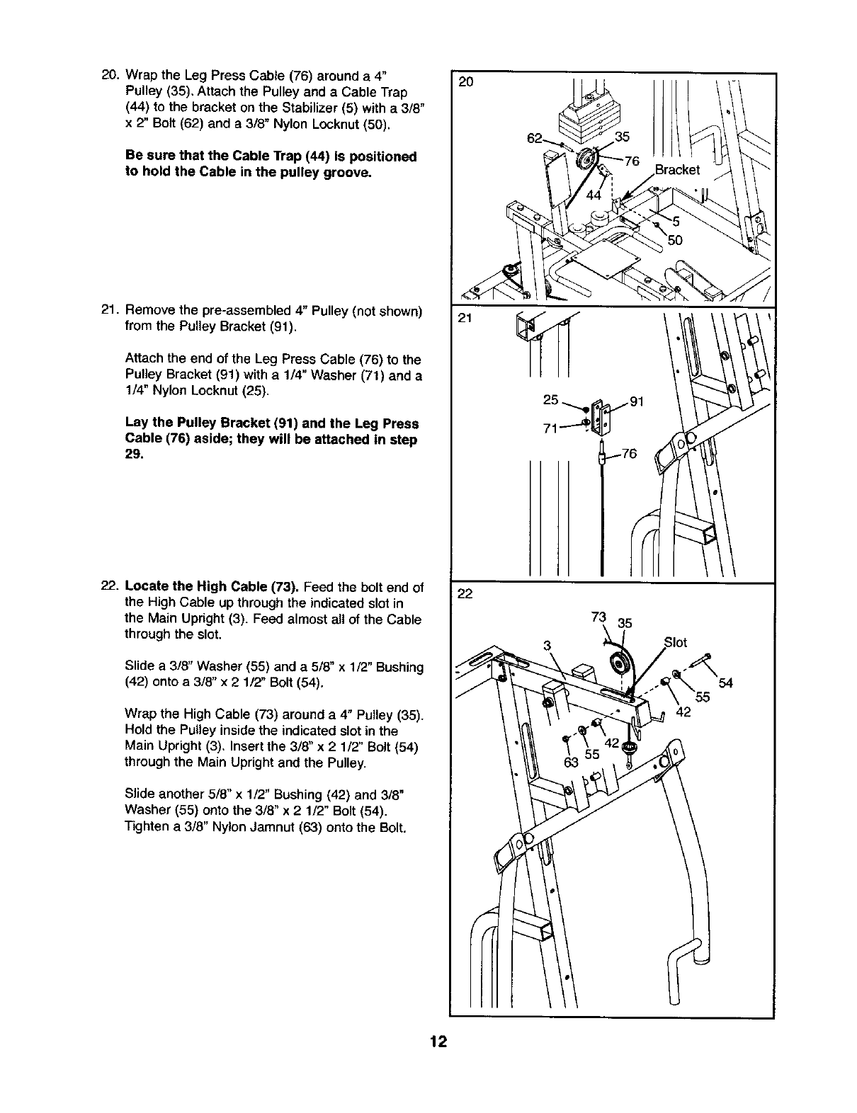
20. Wrap the Leg Press Cable (76) around a 4"
Pulley (35). Attach the Pulley and a Cable Trap
(44) to the bracket on the Stabilizer (5) with a 3/8"
x 2" Bolt (62) and a 3/8" Nylon Locknut (50).
Be sure that the Cable Trap (44) Is positioned
to hold the Cable in the pulley groove.
21. Remove the pre-assembled 4" Pulley (not shown)
from the Pulley Bracket (91).
Attach the end of the Leg Press Cable (76) to the
Pulley Bracket (91) with a1/4" Washer (71) and a
1/4" Nylon Locknut (25),
Lay the Pulley Bracket (91) and the Leg Press
Cable (76) aside; they will be attached in step
29.
22. Locate the High Cable (73). Feed the bolt end of
the High Cable up through the indicated slot in
the Main Upright(3). Feed almost all of the Cable
through the slot.
Slide a 3/8" Washer (55) and a 5/8" x 1/2" Bushing
(42) onto a3/8" x 2 1/2" Bolt (54).
Wrap the High Cable (73) around a4" Pulley (35).
Hold the Pulley insidethe indicated slotin the
Main Upright (3). Insert the 3/8" x 2 1/2" Bolt (54)
through the Main Upright and the Pulley.
Slide another 5/8" x 1/2" Bushing (42) and 3/8"
Washer (55) onto the 3/8" x 2 1/2" Bolt (54).
Tighten a 3/8" Nylon Jamnut (63) onto the Bolt.
2O
21
22
73 35
3
54
42
12
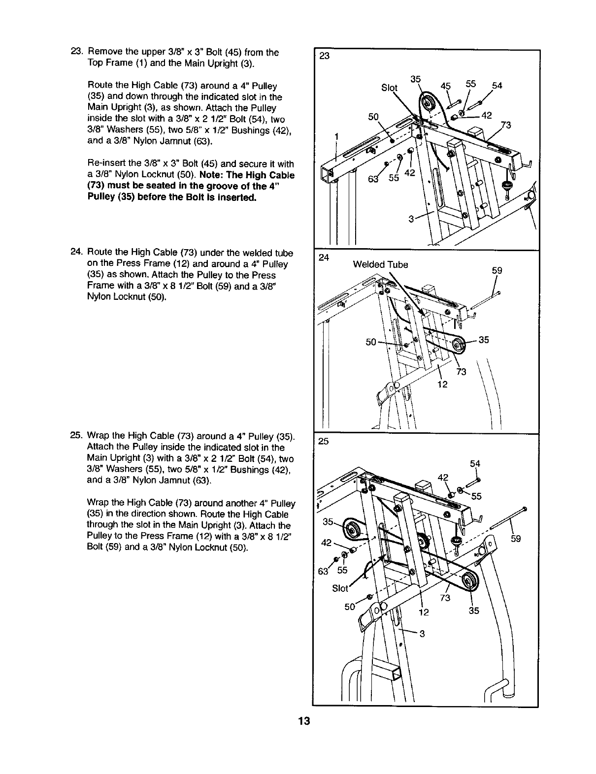
23. Remove the upper 3/8" x 3" Bolt (45) from the
Top Frame (1) and the Main Upright (3).
Route the High Cable (73) around a 4" Pulley
(35) and down through the indicated slot in the
Main Upright (3), as shown. Attach the Pulley
inside the slot with a 3/8" x 2 1/2" Bolt (54), two
3/8" Washers (55), two 5/8" x 1/2" Bushings (42),
and a 3/8" Nylon Jamnut (63).
Re-insert the 3/8" x 3" Bolt (45) and secure it with
a 3/8" Nylon Locknut (50). Note: The High Cable
(73) must be seated in the groove of the 4"
Pulley (35) before the Bolt is inserted.
24. Route the High Cable (73) under the welded tube
on the Press Frame (12) and around a 4" Pultey
(35) as shown. Attach the Pulley to the Press
Frame with a 3/8" x 8 1/2" Bolt (59) and a 3/8"
Nylon Locknut (50).
25. Wrap the High Cable (73) around a 4" Pulley (35).
Attach the Pulley inside the indicated slot in the
Main Upright (3) with a 3/8' x 2 1/2" Bolt (54), two
3/8" Washers (55), two 5/8" x 1/2" Bushings (42),
and a 3/8" Nylon Jamnut (63).
Wrap the High Cable (73) around another 4" Pulley
(35) in the direction shown. Route the High Cable
through the slot inthe Main Upright (3). Attach the
Pulley to the Press Frame (12) with a 3/8" x 8 1/2"
Bolt (59) and a 3/8" Nylon Locknut (50).
23
Slot
5O
1
24 Welded Tube
25
35 45 55 54
59
\
12
54
13
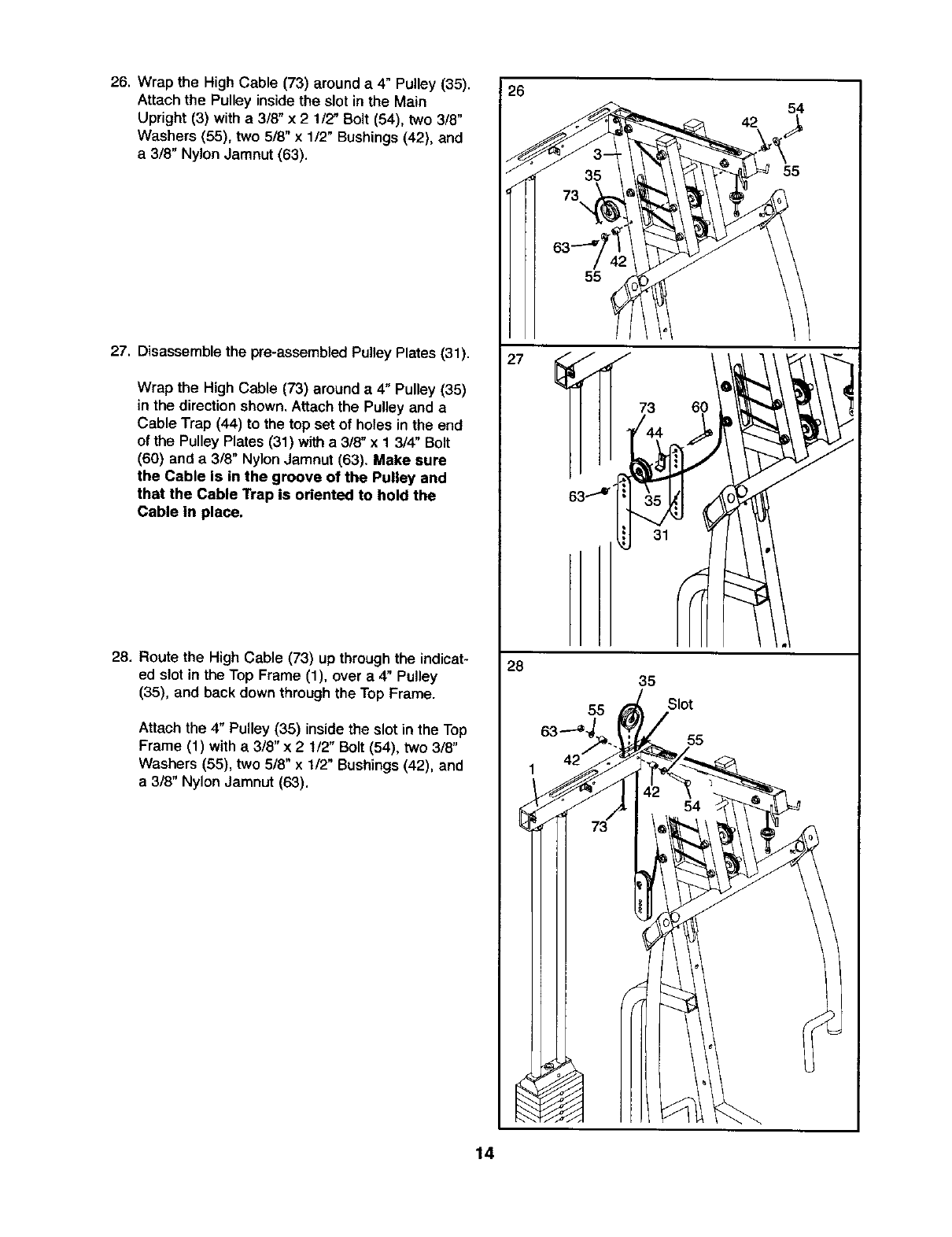
26. Wrap the High Cable (73) around a 4" Pulley (35).
Attach the Pulley inside the slot in the Main
Upright (3) with a 3/8" x 2 1/2" Bolt (54), two 3/8"
Washers (55), two 5/8" x 1/2" Bushings (42), and
a 3/8" Nylon Jamnut (63).
27. Disassemble the pre-assembled Pulley Plates (31).
Wrap the High Cable (73) around e 4" Pulley (35)
in the direction shown. Attach the Pulley and a
Cable Trap (44) to the top set of holes in the end
of the Pulley Plates (31) with a 3/8" x 1 3/4" Bolt
(60) and a 3/8" Nylon Jamnut (63). Make sure
the Cable is in the groove of the Pulley and
that the Cable Trap is oriented to hold the
Cable in place.
28, Route the High Cable (73) up through the indicat-
ed slot in the Top Frame (1), over a 4" Pulley
(35), and back down through the Top Frame.
Attach the 4" Pulley (35) inside the slot in the Top
Frame (1) with a 3/8" x 2 1/2" Bolt (54), two 3/8"
Washers (55), two 5/8" x 1/2" Bushings (42). and
a 3/8" Nylon Jamnut (63).
26
J
J
27
28
55
J
73 60
/44
63"1°"" 35
31
55
73
14
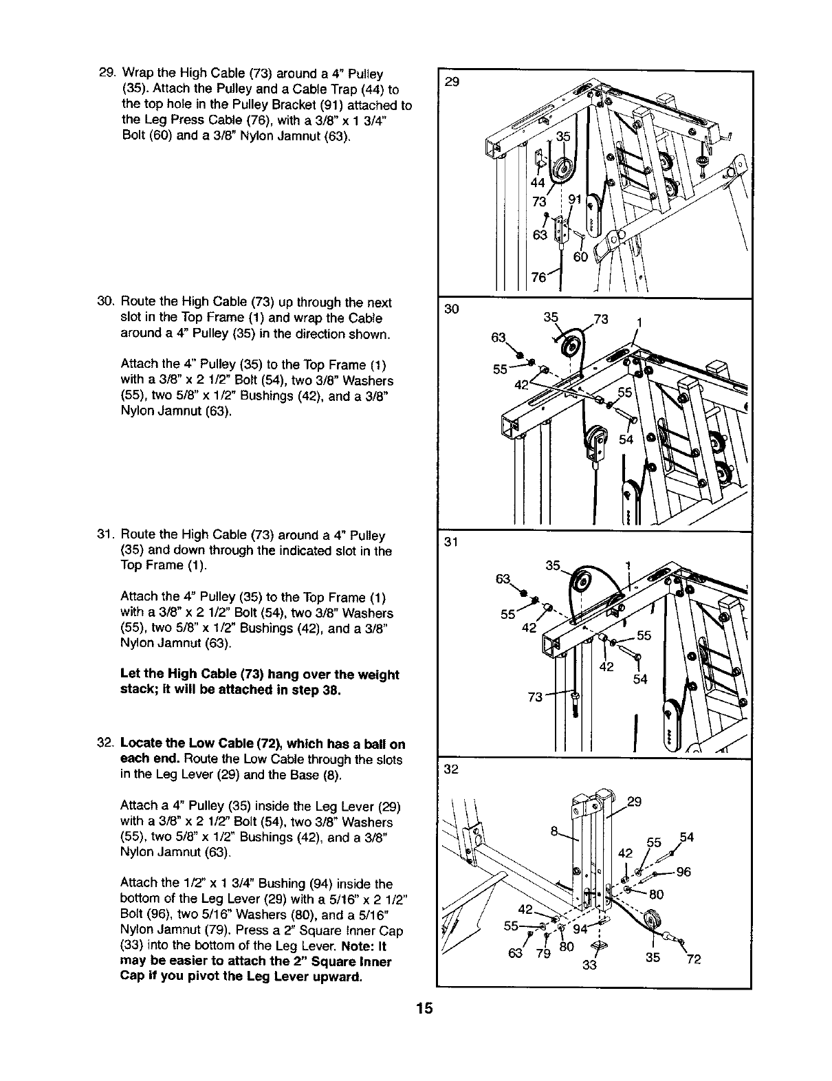
29. Wrap the High Cable (73) around a 4" Pulley
(35). Attach the Pulley and a Cable Trap (44) to
the top ho}e in the Pulley Bracket (91) attached to
the Leg Press Cable (76), with a 3/8" x 1 3/4"
Bolt (60) and a 3/8" Nylon Jamnut (63),
30. Route the High Cable (73) up through the next
slot in the Top Frame (1) and wrap the Cable
around a 4" Pulley (35) in the direction shown.
Attach the 4" Pulley (35) to the Top Frame (1)
with a 3/8" x 2 1/2" Bolt (54), two 318" Washers
(55), two 5/8" x 1/2, Bushings (42), and a 3/8"
Nylon Jamnut (63).
31. Route the High Cable (73) around a 4" Pulley
(35) and down through the indicated slot in the
Top Frame (1).
Attach the 4" Pulley (35) to the Top Frame (1)
w_tha 3/8" x 2 1/2" Bolt (54), two 3/8" Washers
(55), two 5/8" x 1/2" Bushings (42), and a 3/8"
Nylon Jamnut (63).
Let the High Cable (73) hang over the weight
stack; it will be attached in step 38.
32. Locate the Low Cable (72), which has a ball on
each end. Route the Low Cable through the slots
inthe Leg Lever (29) and the Base (8).
Attach a 4" Pulley (35) inside the Leg Lever (29)
with a 3/8" x 21/2" Bolt (54), two 3/8" Washers
(55), two 5/8" x 1/2" Bushings (42), and a 3/8"
Nylon Jamnut (63).
Attach the 1/2" x 13/4" Bushing (94) inside the
bottom of the Leg Lever (29) with a 5/16" x 2 1/2"
Bolt (96), two 5/'16" Washers (80), end a 5/'16"
Nylon Jamnut (79). Press a 2" Square Inner Cap
(33) into the bottom of the Leg Lever. Note: It
may be easier to attach the 2" Square Inner
Cap if you pivot the Leg Lever upward.
29
3O
31
32
J
\
1
63
35
29
55 54
63 79 033 35 72
15
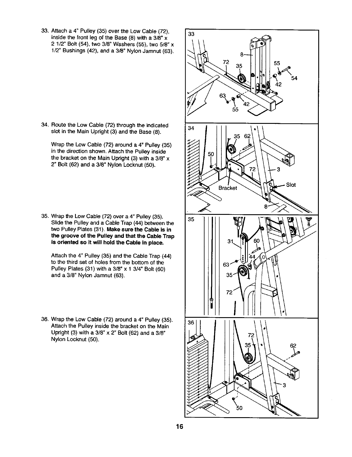
33. Attach a 4" Pulley (35) over the Low Cable (72),
inside the front leg of the Base (8) with a 3/8" x
2 1/2" Bolt (54), two 3/8" Washers (55), two 5/8" x
1/2" Bushings (42), and a 3/8" Nylon Jamnut (63).
34. Route the Low Cable (72) through the indicated
slot in the Main Upright (3) and the Base (8).
Wrap the Low Cable (72) around a 4" Pulley (35)
in the directionshown. Attach the Pulley inside
the bracket on the Main Upright (3) with a 3/8" x
2" Bolt (62) and a 3/8" Nylon Locknut (50),
35. Wrap the Low Cable (72) over a 4" Pulley (35).
Slide the Pulley and a Cable Trap (44) between the
two Pulley Plates (31). Make sure the Cable is in
the groove of the Pulley and that the Cable Trap
iS oriented so It will hold the Cable in place.
Attach the 4" Pulley (35) and the Cable Trap (44)
to the third set of holes from the bottom of the
Pulley Plates (31) with a 3/8" x 1 3/4" Bolt (60)
and a 3/8" Nylon Jamnut (63).
36. Wrap the Low Cable (72) around a 4" Pulley (35),
Attach the Pulley inside the bracket on the Main
Upright (3) with a 3/8" x 2" Bolt (62) and a 3/8"
Nylon Locknut (50).
33
35
5O
62
16
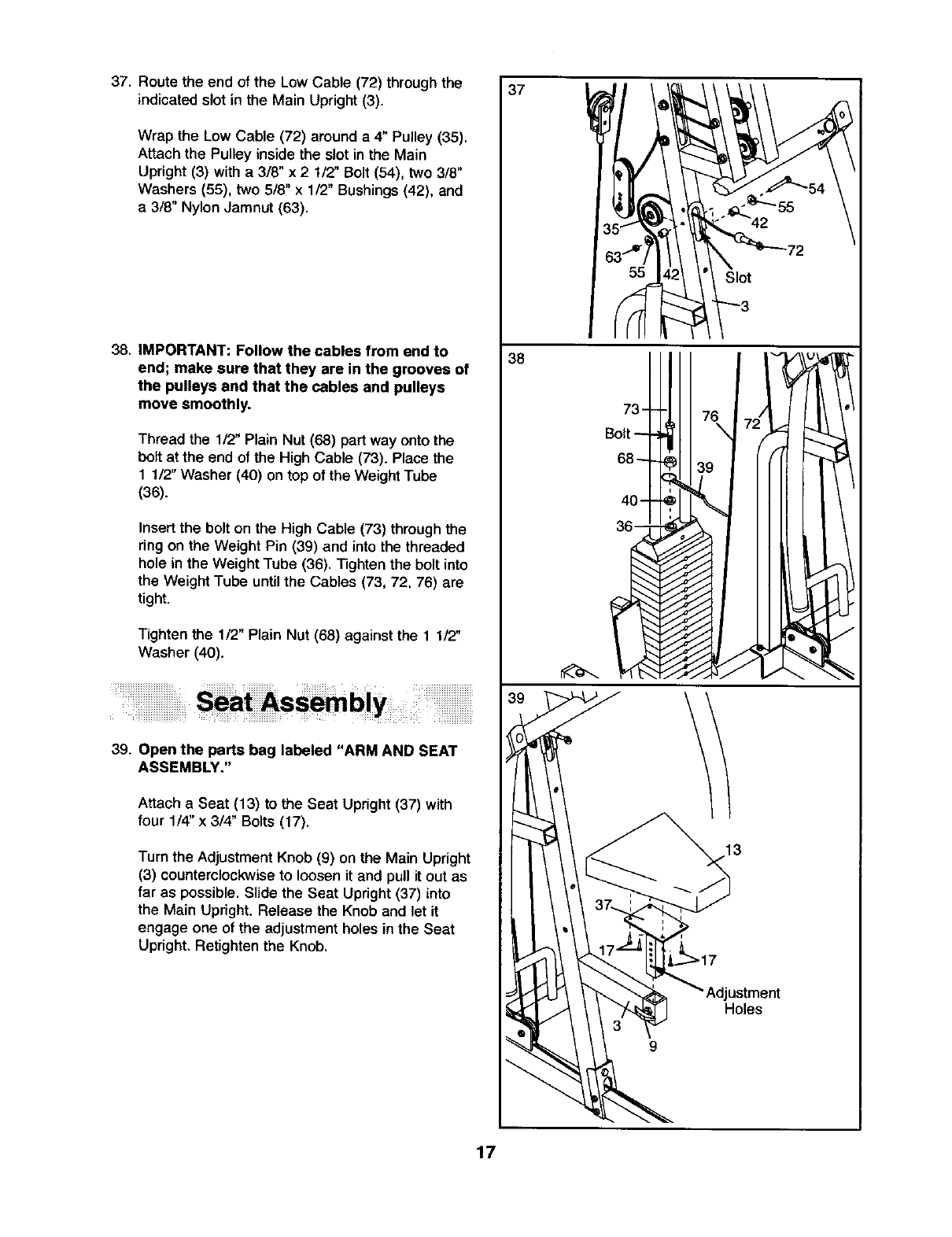
37. Route the end of the Low Cable (72) through the
indicated slot in the Main Upright (3).
Wrap the Low Cable (72) around a 4" Pulley (35).
Attach the Pulley inside the slot in the Main
Upright (3) with a 3/8" x 2 1/2" Bolt (54), two 3/8"
Washers (55), two 5/8" x 1/2" Bushings (42), and
a 3/8" Nylon Jamnut (63).
38, IMPORTANT: Follow the cables from end to
end; make sure that they are in the grooves of
the pulleys and that the cables and pulleys
move smoothly.
Thread the 1/2" Plain Nut (68) part way onto the
bolt at the end of the High Cable (73). Place the
1 1/'Z' Washer (40) on top of the Weight Tube
(36).
Insert the bolt on the High Cable (73) through the
ring on the Weight Pin (39) and into the threaded
hole in the Weight Tube (36). Tighten the bolt into
the Weight Tube until the Cables (73, 72, 76) are
tight.
Tighten the 1/2" Plain Nut (68) against the 1 1/2"
Washer (40).
39. Open the parts bag labeled "ARM AND SEAT
ASSEMBLY,"
Attach a Seat (13) to the Seat Upright (37) with
four 1/4" x 314" Bolts (17).
Turn the Adjustment Knob (9) on the Main Upright
(3) counterclockwise to loosen it and pull it out as
far as possible. Slide the Seat Upright (37) into
the Main Upright. Release the Knob and let it
engage one of the adjustment holes in the Seat
Upright. Retighten the Knob.
37
38
1 --3
tj
73 76
Bolt
\
13
Jstment
Holes
17
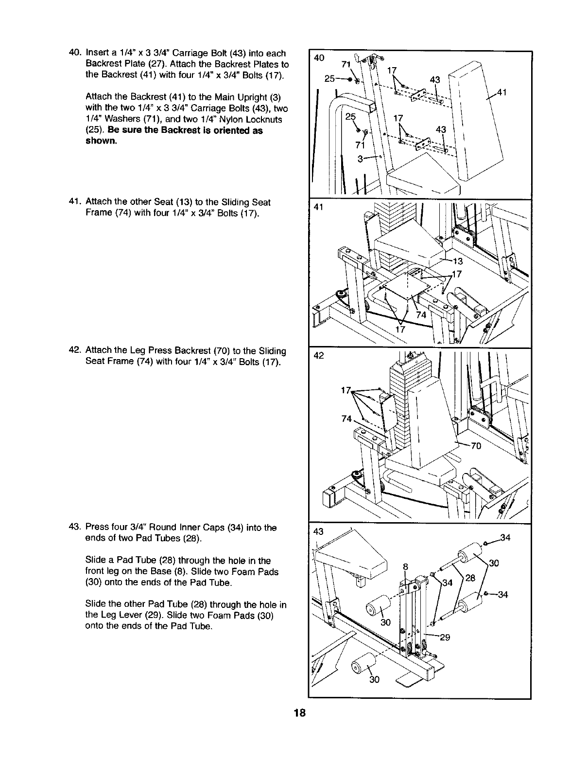
40. Insert a 1/4" x 3 3/4" Carriage Bolt (43) into each
Backrest Plate (27). Attach the Backrest Plates to
the Backrest (41) with four 1/4" x 3/4" Bolts (17).
Attach the Backrest (41) to the Main Upright (3)
with the two 1/4" x 3 3/4" Carriage Bolts (43), two
114"Washers (71), and two 1/4" Nylon Locknuts
(25). Be sure the Backrest is oriented as
shown.
41. Attach the other Seat (13) to the SlidingSeat
Frame (74) with four 1/4" x 3/4" Bolts (17).
42, Attach the Leg Press Backrest (70) to the Sliding
Seat Frame (74) with four 1/4" x 3/4" Botts (17).
43. Press four 3/4" Round Inner Caps (34) into the
ends of two Pad Tubes (28).
Slide aPad Tube (28) through the hole in the
front leg on the Base (8). Slide two Foam Pads
(30) onto the ends of the Pad Tube.
Slide the other Pad Tube (28) through the hole in
the Leg Lever (29). Slide two Foam Pads (30)
onto the ends of the Pad Tube.
41
42
17
\
30
43
8
18
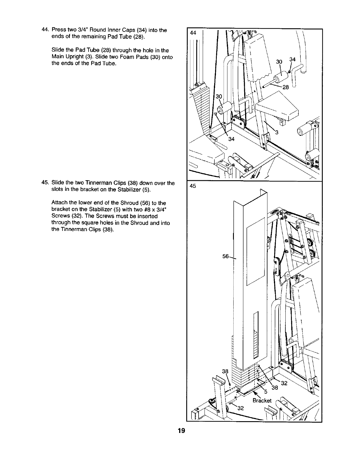
44. Press two 3/4" Round Inner Caps (34) into the
ends of the remaining Pad Tube (28).
Slide the Pad Tube (28) through the hole in the
Main Upright (3). Slide two Foam Pads (30) onto
the ends of the Pad Tube.
45. Slide the two "rinnerman Clips (38) down over the
slots in the bracket on the Stabilizer (5).
Attach the lower end o{ the Shroud (56) to the
bracket on the Stabilizer (5) with two #8 x 3/4"
Screws (32). The Screws must be inserted
through the square holes in the Shroud and into
the Tinnerman Clips (38),
45
56_
38
19
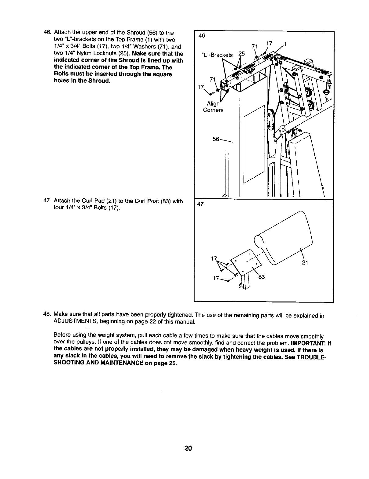
46. Attach the upper end of the Shroud (56) to the
two "L"-brackets on the Top Frame (1) with two
1/4" x 3/4" Bolts (17), two 1/4" Washers (71), and
two 1/4" Nylon Locknuts (25). Make sure that the
indicated corner of the Shroud is lined up with
the indicated corner of the Top Frame. The
Bolts must be inserted through the square
holes in the Shroud.
47. Attach the (_url Pad (21) to the Curl Post (83) with
four 1/4" x 3/4" Bolts (17).
46
71
Align
Corners
47
71
21
48. Make sure that all parts have been properly tightened. The use of the remaining parts will be explained in
ADJUSTMENTS, beginning on page 22 of this manual.
Before usingthe weight system, pull each cable afew times to make sure that the cables move smoothly
over the pulleys. If one of the cables does not move smoothly, find and correct the problem, iMPORTANT: If
the cables are not properly installed, they may be damaged when heavy weight is used. If there is
any slack in the cables, you will need to remove the slack by tightening the cables. See TROUBLE-
SHOOTING AND MAINTENANCE on page 25.
20
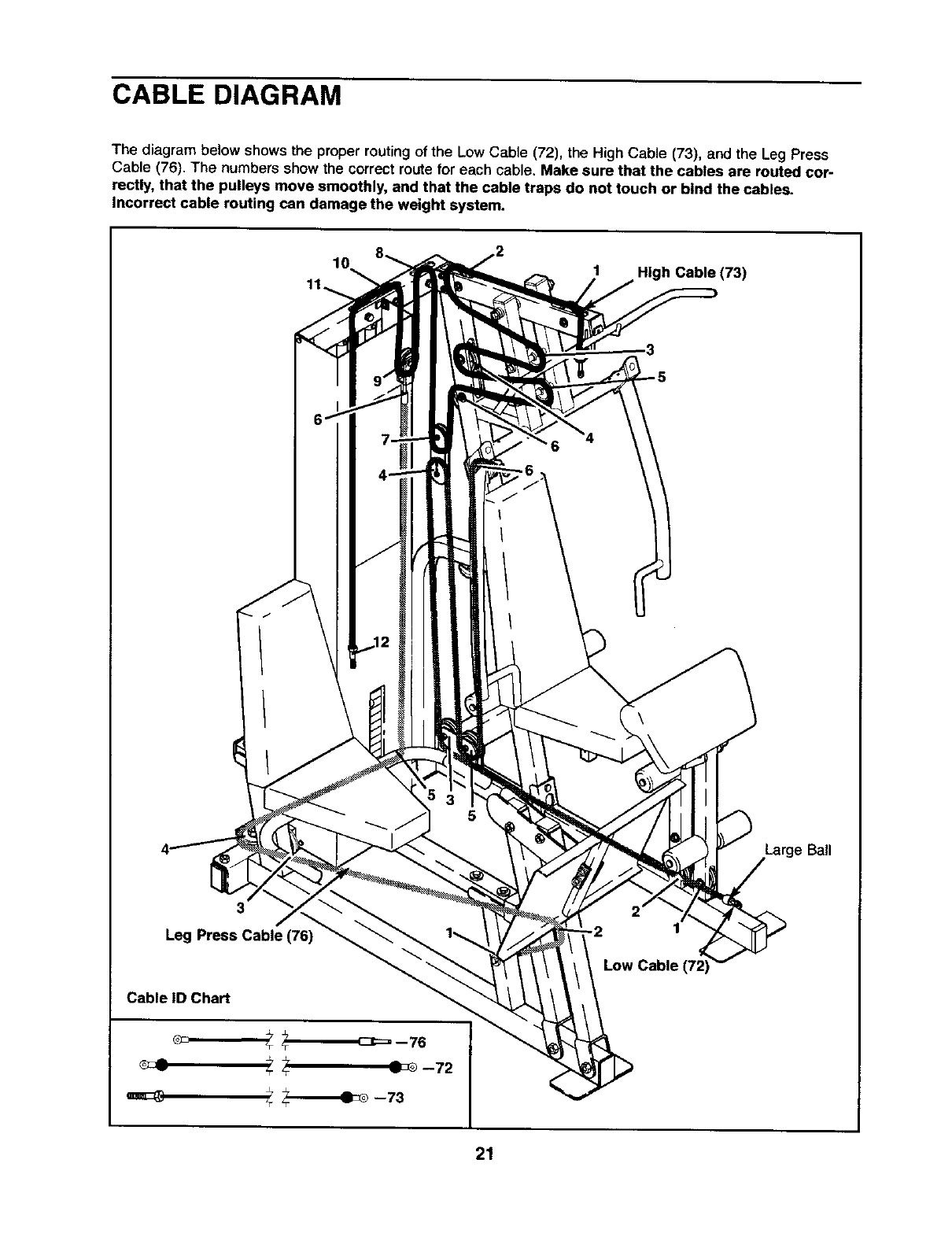
CABLE DIAGRAM
The diagram below shows the proper routing of the Low Cable (72), the High Cable (73), and the Leg Press
Cable (76). The numbers show the correct route for each cable. Make sure that the cables are routed cor-
rectly, that the pulleys move smoothly, and that the cable traps do not touch or bind the cables.
Incorrect cable routing can damage the weight system.
1 High Cable (73)
Large Ball
3
Leg Press Cable (76)
21
ADJUSTMENTS
The instructions below describe how each part of the weight system can be adjusted. Refer to the exercise
guide accompanying this manual to see how the weight system should be set up for each exercise. IMPOR-
TANT: When attaching the lat bar, ankle strap, or ab strap, make sure that the accessories are In the cor-
rect starting position for the exercise to be performed. If there is any slack in the cables or chain as an
exercise is performed, the effectiveness of the exercise will be reduced.
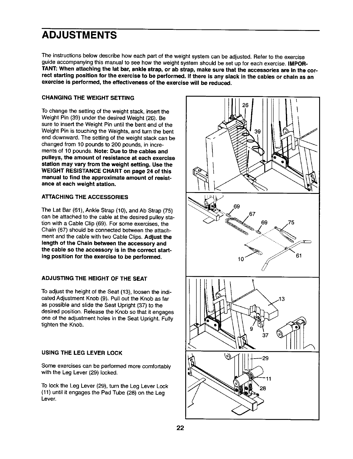
CHANGING THE WEIGHT SETTING
To change the setting of the weight stack, insert the
Weight Pin (39) under the desired Weight (26). Be
sure to insert the Weight Pin until the bent end of the
Weight Pin is touching the Weights, and turn the bent
end downward. The setting of the weight stack can be
changed from 10 pounds to 200 pounds, in incre-
ments of 10 pounds, Note: Due to the cables and
pulleys, the amount of resistance at each exercise
station may vary from the weight setting. Use the
WEIGHT RESISTANCE CHART on page 24 of this
manual to find the approximate amount of resist-
ance at each weight station.
ATTACHING THE ACCESSORIES
The Lat Bar (61), Ankle Strap (10), and Ab Strap (75)
can be attached to the cable at the desired pulley sta-
tion with a Cable Clip (69). For some exercises, the
Chain (67) should be connected between the attach-
ment and the cable with two Cable Clips. Adjust the
length of the Chain between the accessory and
the cable so the accessory is in the correct start-
ing position for the exercise to be performed,
ADJUSTING THE HEIGHT OF THE SEAT
To adjust the height of the Seat (13), loosen the indi-
cated Adjustment Knob (9). Pull out the Knob as far
as possible and slide the Seat Upright (37) to the
desired position. Release the Knob so that it engages
one of the adjustment holes in the Seat Upright. Fully
tighten the Knob.
USING THE LEG LEVER LOCK
Some exercises can be performed more comfortably
with the Leg Lever (29) locked.
To lock the Leg Lever (29), turn the Leg Lever Lock
(11) until it engages the Pad Tube (28) on the Leg
Lever.
22
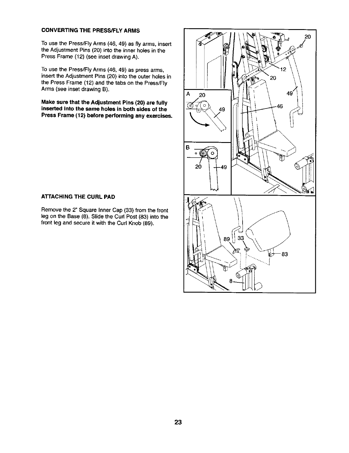
CONVERTING THE PRESS/FLY ARMS
To use the Press/Fly Arms (46, 49) as fly arms, insert
the Adjustment Pins (20) into the inner holes in the
Press Frame (12) (see inset drawing A).
To use the Press/Fly Arms (46, 49) as press arms,
insert the Adjustment Pins (20) into the outer holes in
the Press Frame (12) and the tabs on the Press/Fly
Arms (see inset drawing B).
Make sure that the Adjustment Pins (20) are fully
inserted into the same holes in both sides of the
Press Frame (12) before performing any exercise_
ATTACHING THE CURL PAD
Remove the 2" Square Inner Cap (33) from the front
leg on the Base (8). Slide the Curl Post (83) into the
front leg and secure it with the Curl Knob (89).
A 20
20 -49
20
23
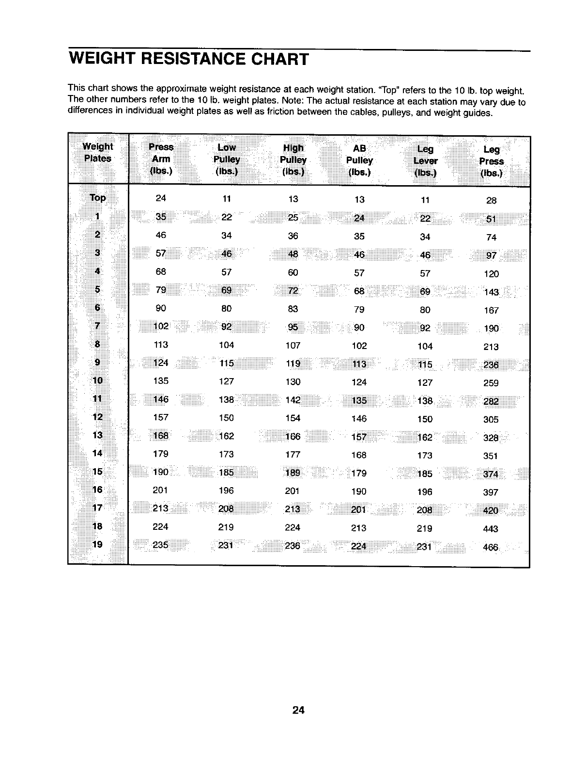
WEIGHT RESISTANCE CHART
This chart shows the approximate weight resistance at each weight station. "Top" refers to the 10 lb. top weight.
The other numbers refer to the 10 lb. weight plates. Note: The actual resistance at each station may vary due to
differences in individual weight plates as wel! as friction between the cables, pulleys, and weight guides.
Top 24 11
34
3 I 57 46
i
468 57
13 13 11 28
36 35 34 74
60 57 57 120
72 68 69 143
83 79 80 167
92 190
8 113 104 107 102 104 213
9_124 115 119 113 115 236
10 135 127 130 124 127 259
11 146 138 142 135 138 282
150 154 146 150 305
162 166 t57 162 328
173
I,o0 ,.
201 196
224 219
!iiiiiiiiiiiiiiiiil
177 168 173 351
179 185:574
201 190 196 397
224 213 219 443
24
TROUBLE-SHOOTING AND MAINTENANCE
Make sure all parts are properly tightened each time you use the weight system. Replace any worn parts immedi-
ately. The weight system can be cleaned using a damp cloth and mild non-abrasive detergent. Do not use solvents.
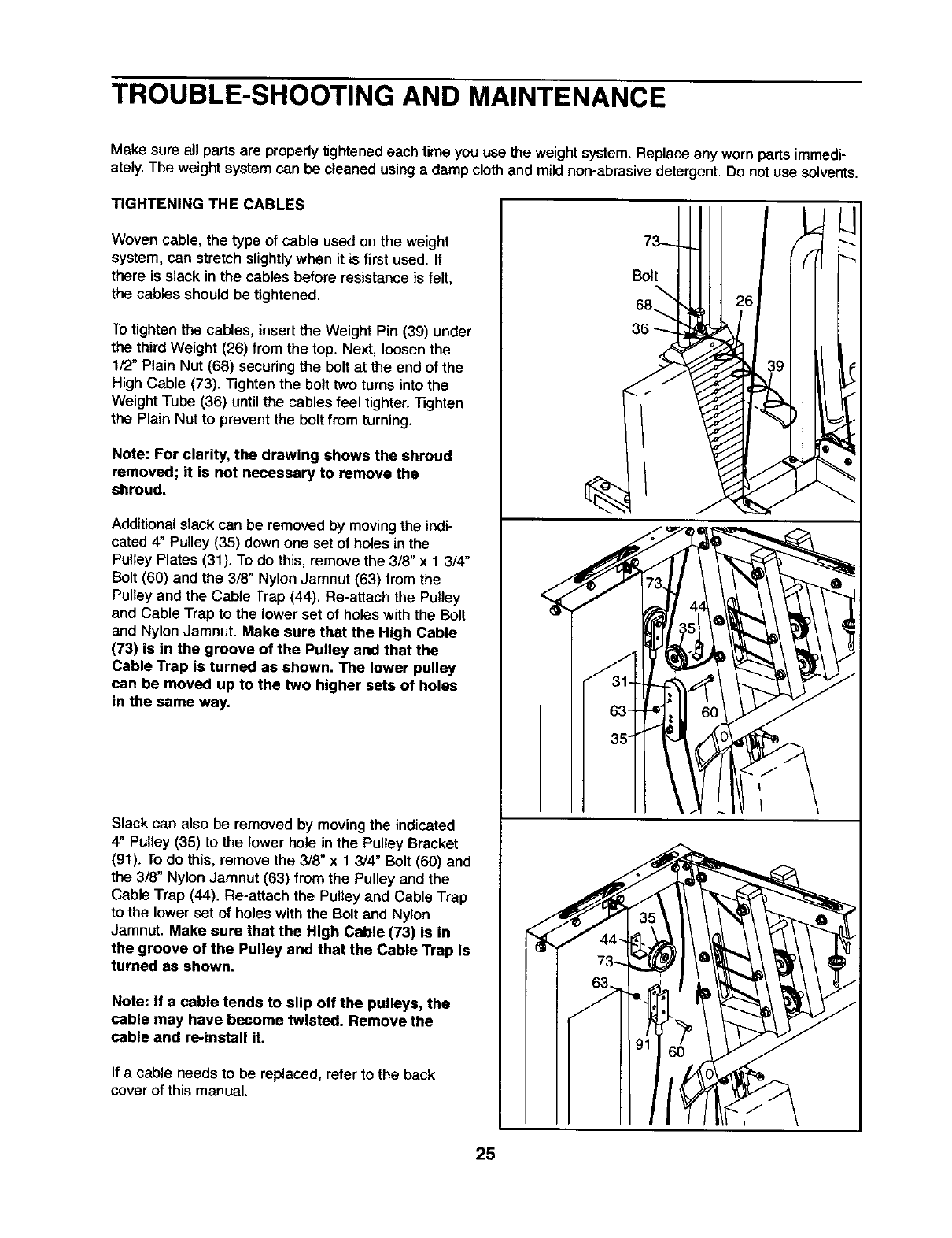
TIGHTENING THE CABLES
Woven cable, the type of cable used on the weight
system, can stretch slightly when it is first used. If
there is slack in the cables before resistance is felt,
the cables should be tightened.
To tighten the cables, insert the Weight Pin (39) under
the third Weight (26) from the top. Next, loosen the
1/2" Plain Nut (68) securing the bolt at the end of the
High Cable (73). Tighten the bolt two turns into the
Weight Tube (36) until the cables feel tighter. "lighten
the Plain Nut to prevent the bolt from turning.
Note: For clarity, the drawing shows the shroud
removed; it is not necessary to remove the
shroud.
Additional slack can be removed by moving the indi-
cated 4" Pulley (35) down one set of holes in the
Pulley Plates (31). To do this, remove the 3/8" x 1 314°
Bolt (60) and the 3/8" Nylon Jamnut (63) from the
Pulley and the Cable Trap (44). Re-attach the Pulley
and Cable Trap to the lower set of holes with the Bolt
and Nylon Jamnut. Make sure that the High Cable
(73) is in the groove of the Pulley and that the
Cable Trap is turned as shown. The lower pulley
can be moved up to the two higher sets of holes
in the same way.
Slack can also be removed by moving the indicated
4" Pulley (35) to the lower hole in the Pulley Bracket
(91). To do this, remove the 3/8" x 1 3/4" Bolt (60) and
the 3/8" Nylon Jamnut (63) from the Pulley and the
Cable Trap (44). Re-attach the Pulley and Cable Trap
to the lower set of holes with the Bolt and Nylon
Jamnut. Make sure that the High Cable (73) is in
the groove of the Pulley and that the Cable Trap is
turned as shown.
Note: If a cable tends to slip off the pulleys, the
cable may have become twisted. Remove the
cable and re-install it.
If a cable needs to be replaced, refer to the beck
cover of this manual.
I
Bolt
68..
36
25
EXERCISE GUIDELINES
THE FOUR BASIC TYPES OF WORKOUTS
Muscle Building
To increase the size and strength of your muscles,
push them close to their maximumcapacity. Your mus-
cles wiltcontinually adapt and grow as you progres-
sively increase the intensityof your exercise. You can
adjust the intensitylevel of an individualexercise in
two ways:
• by changingthe amount of weight used
•by changingthe number of repetitionsor sets per-
formed. (A "repetition" is one complete cycle of an
exercise, such as one sit-up. A "set" is a series of
repetitions.)
The proper amount of weight for each exercise
depends uponthe individualuser. You must gauge
your limits and select the amount of weight that is dght
for you. Begin with 3 sets of 8 repetitions for each
exercise you perform. Rest for 3 minutes after each
set. When you can complete 3 sets of 12 repetitions
without difficulty, increase the amount of weight.
Toning
Youcan tone your musclesby pushing them to a mod-
erate percentage of their capacity. Select a moderate
amount of weight and increase the number of repeti-
tions in each set. Complete as many sets of 15 to 20
repetitionsas possible without discomfort.Rest for 1
minute after each set. Work your muscles by complet-
ing more sets rather than by using highamounts of
weight.
Weight Loss
To lose weight, use a low amount of weight and
increase the number of repetitionsin each set.
Exercisefor 20 to 30 minutes,restingfor amaximum
of 30 seconds between sets.
Cross Training
Cross training is an efficient way to get a complete and
welt-balanced fitness program.An example of a bal-
anced program is:
• Plan weight training workoutson Monday,
Wednesday, and Friday.
•Plan 20 to 30 minutes of aerobic exercise, such as
cyclingor swimming, on Tuesday and Thursday.
• Rest from both weight training and aerobic exercise
for at least one full day each week to give your body
time to regenerate.
The combination of weight training and aerobic exer-
cise will reshape and strengthen your body, plus devel-
op your heart and lungs.
PERSONALIZING YOUR EXERCISE PROGRAM
Determining the exact length of time for each workout,
as well as the number of repetitions or sets completed,
is an individual matter, It is important to avoid overdo-
ing it duringthe first few months of your exercise pro-
gram. You should progress at your own pace and be
sensitive to your body's signals. If you experience pain
or dizziness at any time while exercising, stop immedi-
ately and begin cooling down. Find out what is wrong
before continuing. Remember that adequate rest and a
proper diet are important factors in any exercise pro-
gram.
WARMING UP
Begin each workoutwith 5 to 10 minutes of stretching
and lightexercise to warm up. Warming up prepares
your body for more strenuous exercise by increasing
circulation, raising your body temperature and deliver*
ing more oxygen to your muscles.
WORKING OUT
Each workoutshould include6 to 10 differentexercis-
es. Select exercises for every major muscle group,
emphasizing areas that you want to develop most. To
give balance and variety to your workouts, vary the
exercises from session to session.
Schedule your workouts for the time of day when your
energy level is the highest. Each workout should be
followed by at least one day of rest. Once you find the
schedule that is right for you, stick with it.
EXERCISE FORM
Maintainingproper form is an essential part of an
effective exercise program. This requires moving
through the full range of motion for each exercise, and
moving only the appropriate parts of the body.
Exercising in an uncontrolled manner will leave you
feeling exhausted. On the exercise guide accompany-
ing this manual you wilt find photographs showing the
correct form for several exercises, and a list of the
muscles affected. Refer to the muscle chart on page
27 to find the names of the muscles.
The repetitions in each set should be performed
smoothly and without pausing. The exertion stage of
each repetition should last about half as long as the
return stage. Prober breathing is important, Exhale
during the exertion stage of each repetition and inhale
during the return stroke. Never hold your breath.
26
Rest for a short period of time after each set. The
ideal resting periods are:
• Rest for three minutes after each set for a muscle
building workout.
•Rest for one minute after each set for a toning work-
out.
• Rest for 30 seconds after each set for a weight loss
workout.
Plan to spend the first couple of weeks familiarizing
yourself with the equipment and learning the proper
form for each exercise,
COOLING DOWN
End each workout with 5 to 10 minutes of stretching.
Include stretches for both your arms and legs. Move
slowly as you stretchand do not bounce. Ease into
each stretchgradually and go only as far as you can
without strain. Stretching at the end of each workout
is an effective way to increase flexibility.
STAYING MOTIVATED
For motivation, keep arecord of each workout, List
the date, the exercises performed, the weight used,
and the numbers of sets and repetitions completed.
Record your weight and key body measurements at
the end of every month. Remember, the key to
achieving the greatest results is to make exercise a
regular and enjoyable part of your everyday life.
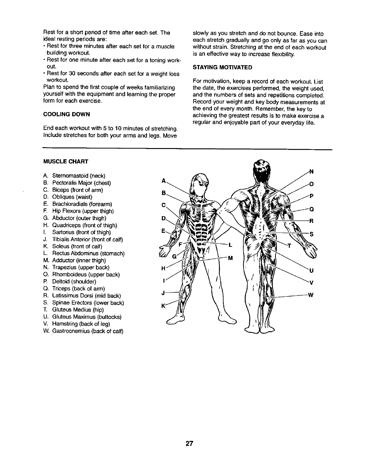
MUSCLE CHART
A. Sternomastoid (neck)
B. Pectoralis Major (chest)
C. Biceps (front of arm)
D. Obliques (waist)
E. Brachioradials (forearm)
E Hip Flexors (upper thigh)
G. Abductor (outer thigh)
H. Quadriceps (front of thigh)
I. Sartonus (front of thigh)
J. ]]bialisAnterior (front of calf)
K. Soleus (front of calf)
L. Rectus Abdominus (stomach)
M, Adductor (inner thigh)
N. Trapezius (upper back)
O. Rhomboideus (upper back)
P, Deltoid (shoulder)
Q. Triceps (back of arm)
R. Latissimus Dorsi (mid back)
S. Spinae Erectors (lower back)
T. Gluteus Medius (hip)
U. Gluteus Maximus (buttocks)
V, Hamstring (back of leg)
W. Gastrocnemius (back of calf)
B_
C\
D._ -R
S
27
This chart is provided to help you identify the small parts used in assembly. The number in parenthesis below
each pert refers to the key number of the part from the PART LIST in the center of this manual. Important:
Some parts may have been pre-assembled for shipping. If you cannot find a part in the parts bags,
check to see if it has been pre-assembled.
Note: Assembly is divided into four stages: 1) frame assembly, 2) arm
assembly, 3) cable assembly, and 4) seat assembly. The hardware for
each stage is packaged separately. Wait until you begin each stage to
open the parts bag for that stage.
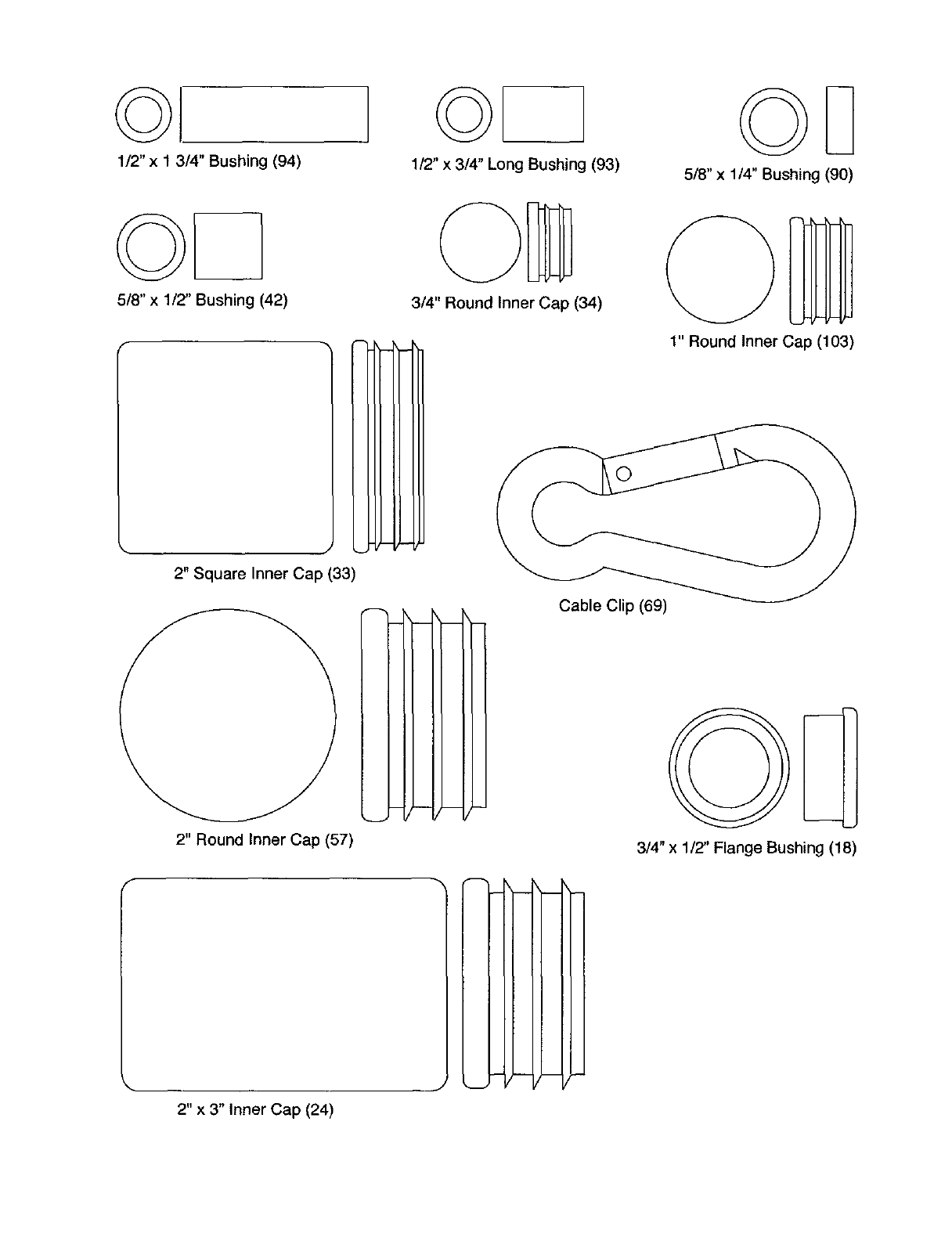
1/2" x 1 3/4" Bushing (94)
©
1/2" x 314" Long Bushing (93) 5/8"x 1/4" Bushing (90)
5/8" x 1/2" Bushing (42)
f
J
2" Square Inner Cap (33)
2" Round Inner Cap (57)
3/4" Round Inner Cap (34)
1" Round inner Cap (103)
Cable Clip (69)
3/4" x 1/2" Flange Bushing (18)
f
2" x 3" Inner Cap (24)
J
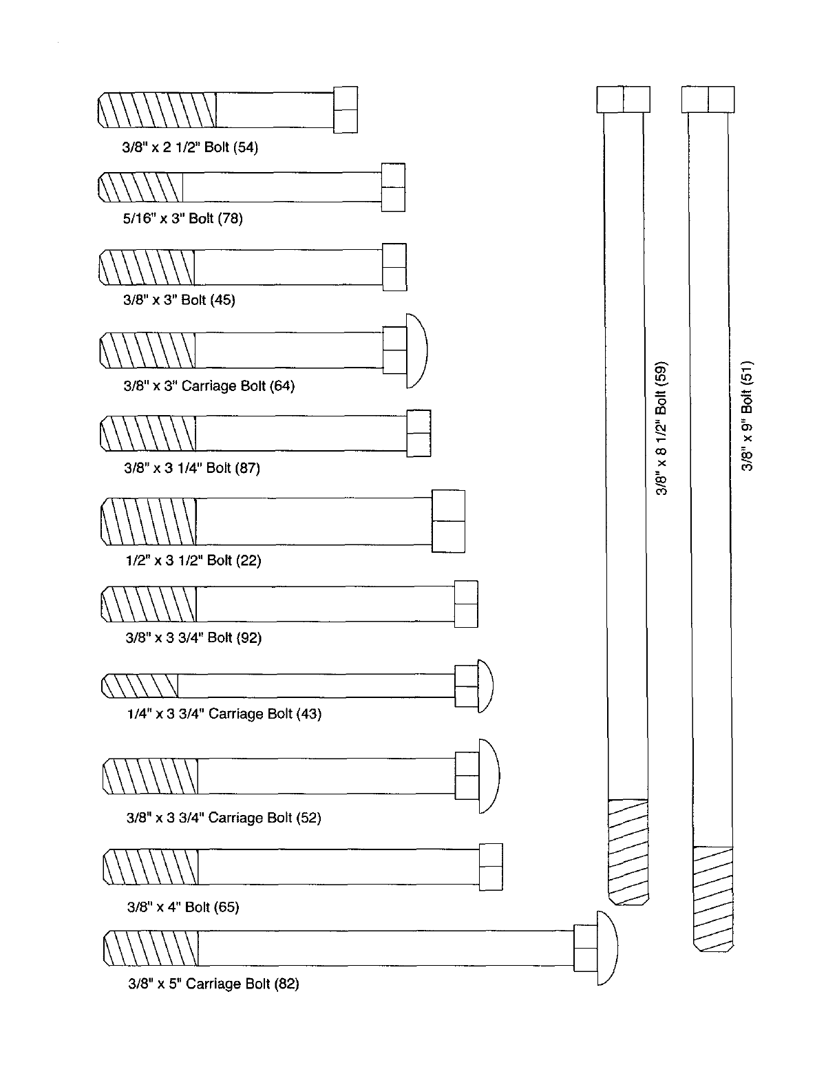
3/8" x 2 1/2" Bolt (54)
5/16" x 3" Bolt (78)
3/8" x 3" Bolt (45)
3/8" x 3" Carriage Bolt (64)
3/8" x 3 1/4" Bolt (87)
1/2" x 3 1/2" Bolt (22)
3/8" x 3 3/4" Bolt (92)
1/4" x 3 3/4" Carriage Bolt (43)
3/8" x 3 3/4" Carriage Bolt (52)
3/8" x 4" Bolt (65)
3/8" x 5" Carriage Bolt (82)
J
J
J
J
J
J
J
o
m
X
03
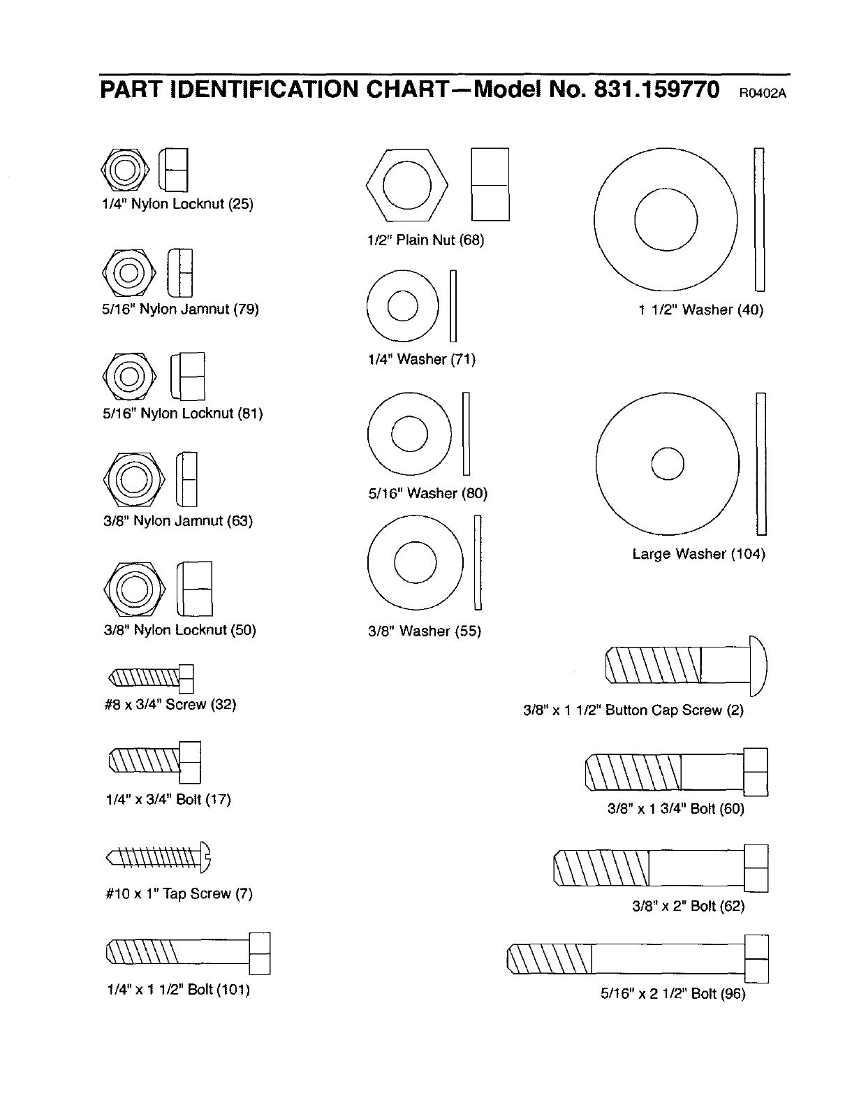
PART IDENTIFICATION CHART--Model No. 831.159770 Ro.o_
1/4" Nylon Locknut (25)
5/16" Nylon Jamnut (79)
5/16" Nylon Locknut (81)
3/8" Nylon Jamnut (63)
3/8" Nylon Locknut (50)
#8 x 3/4" Screw (32)
1/4" x 3/4" Bolt (17)
1/2" Plain Nut (68)
1/4 Washer (71)
5/16" Washer (80)
3/8" Washer (55)
1
1 1/2" Washer (40)
Large Washer (104)
3/8" x 1 1/2" Button Cap Screw (2)
3/8" x 1 3/4" Bolt (60)
<\\\\\\i\:%1\\_
#10 x 1" Tap Screw (7)
1/4"x 1 1/2" Bolt (101)
3/8" x 2" Bolt (62)
_\\\\\\1
5/16" x 2 1/2" Bolt (96)
SAVE THIS PART LIST/EXPLODED DRAWING FOR FUTURE REFERENCE
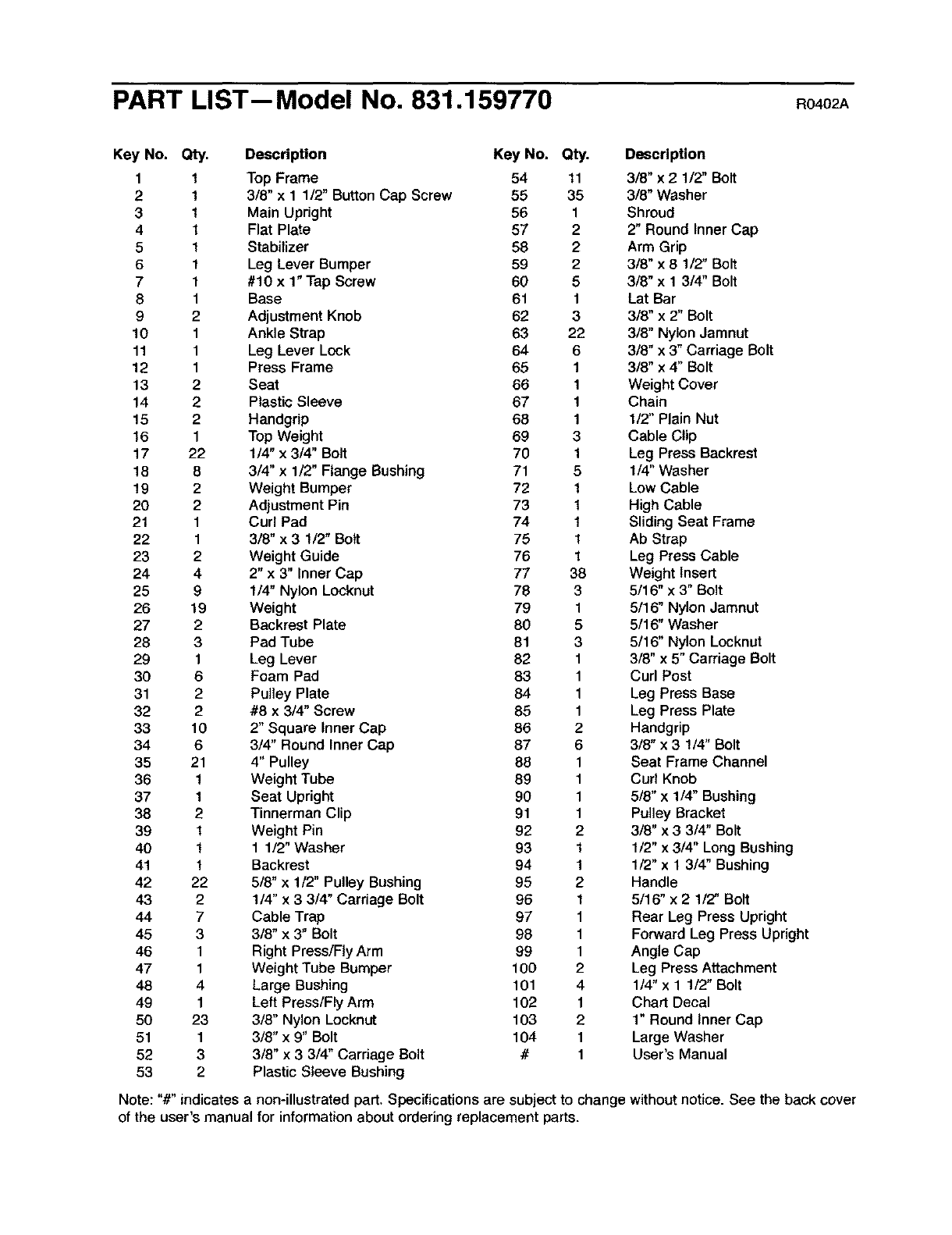
PART LIST-- Model No. 831.159770 Ro4o
Key No. Qty. Description Key No. Qty. Description
1 1 Top Frame 54 11 3/8" x 2 1/2" Bolt
2 1 3/8" x 1 1/2" ButtonCap Screw 55 35 3/8" Washer
3 1 Main Upright 56 1 Shroud
4 1 Flat Plate 57 2 2" Round Inner Cap
51Stabilizer 58 2 Arm Grip
6 1 Leg Lever Bumper 59 2 3/8" x 8 1/2" Bolt
7 1 #10 x 1" Tap Screw 60 5 3/8" x 1 3/4" Bolt
8 1 Base 61 1 Lat Bar
9 2 Adjustment Knob 62 3 3/8" x 2" Bolt
10 1 Ankle Strap 63 22 3/8" Nylon Jamnut
11 1 Leg Lever Lock 64 6 3/8" x 3" Carriage Bolt
12 1 Press Frame 65 1 3/8" x 4" Bolt
13 2Seat 66 1 Weight Cover
14 2 Plastic Sleeve 67 1 Chain
15 2 Handgrip 68 1 1/2" Plain Nut
16 1 Top Weight 69 3 Cable Clip
17 22 1/4" x 3/4" Bolt 70 1 Leg Press Backrest
18 8 3/4" x 1/2" Flange Bushing 71 5 1/4" Washer
19 2 Weight Bumper 72 1 Low Cable
20 2 Adjustment Pin 73 1 High Cable
21 1 Curl Pad 74 1 Sliding Seat Frame
22 1 3/8" x 3 1/2" Bolt 75 1 Ab Strap
23 2 Weight Guide 76 1 Leg Press Cable
24 4 2" x 3" Inner Cap 77 38 Weight Insert
25 9 1/4" Nylon Locknut 78 3 5/16" x 3" Bolt
26 19 Weight 79 1 5/16" Nylon Jamnut
27 2 Backrest Plate 80 5 5/16" Washer
28 3 Pad Tube 81 3 5/16" Nylon Locknut
29 1 Leg Lever 82 1 3/8" x 5" Carriage Bolt
30 6 Foam Pad 83 1 Curl Post
31 2 Pulley Plate 84 1 Leg Press Base
32 2 #8 x 3/4" Screw 85 1 Leg Press Plate
33 10 2" Square Inner Cap 86 2 Handgrip
34 6 3/4" Round Inner Cap 87 6 3/8" x 3 1/4" Bolt
35 21 4" Pulley 88 1 Seat Frame Channel
36 1 Weight Tube 89 1 Curl Knob
37 1 Seat Upright 90 1 5/8" x 1/4" Bushing
38 2 Tinnerman Clip 91 1 Pulley Bracket
39 1 Weight Pin 92 2 3/8" x 3 3/4" Bolt
40 1 1 1/2" Washer 93 1 1/2" x 3/4" Long Bushing
41 1 Backrest 94 1 1/2" x 1 3/4" Bushing
42 22 5/8" x 1/2" Pulley Bushing 95 2 Handle
43 2 1/4" x 3 3/4" Carriage Belt 96 1 5/16" x 2 1/2" Bolt
44 7 Cable Trap 97 1 Rear Leg Press Upright
45 3 3/8" x 3" Bolt 98 1 Forward Leg Press Upright
46 1 Right Press/Fly Arm 99 1 Angle Cap
47 1 Weight Tube Bumper 100 2 Leg Press Attachment
48 4 Large Bushing 101 4 114"x 1 112"Bolt
49 1 Left Press/Fly Arm 102 1 Chart Decal
50 23 3/8" Nylon Locknut 103 2 1" Round Inner Cap
51 1 3/8" x 9" Bolt 104 1 Large Washer
52 3 3/8" x 3 3/4" Carriage Bolt #1 User's Manual
53 2 Plastic Sleeve Bushing
Note: "#" indicates a non-illustrated part. Specifications are subject to change withoutnotice. See the back cover
of the user's manual for information about ordering replacement parts.
55
18 22
18 30
g6
3O 55
34
33 42
44
3_
::o
0
0
ORDERING REPLACEMENT PARTS
To order replacement parts, simply call our Customer Service Departmenttoll-free at 1-888-825-2588, Monday
through Friday, 6 a.m. until 6 p.m. Mountain Time (excluding holidays). To help us assist you, please be pre-
pared to give the following information:
1. The MODEL NUMBER of the product (831.159770)
2. The NAME of the product (NordicTrack ®VERTEX 670 weight system)
3. The SERIAL NUMBER of the product (see the front cover of this manual)
4. The KEY NUMBER and DESCRIPTION of the part(s) (see the PART LIST and EXPLODED DRAWING in the
center of this manual),
LIMITED WARRANTY
WHAT IS COVERED--The entire NordicTrack _*VERTEX 670 weight system ("Product") is warranted to be free of all defects in mate-
rial and workmanship.
WHO IS COVERED--The original purchaser or any person receiving the Product as agift from the original purchaser.
HOW LONG IS IT COVERED--ICON Health & Fitness, Inc. ("ICON"), warrants the product for one year after the date of purchase.
Labor is covered for one year.
WHAT WE DO TO CORRECT COVERED DEFECTS --We will ship to you, without charge, any replacement part or component, pro-
viding the repairs are authorized by ICON first and are performed by an ICON trained and authorized service provider, or, at our
option, we will replace the Product.
WHAT IS NOT COVERED--Any failures or damage caused by unauthorized service, misuse, occident, negligence, improper
assembly or installation, alterations, modifications without our written authorization or by failure on your part to use, operate, and
maintain as set out in your User's Manual ("Manual').
WHAT YOU MUST DO--Always retain proof of purchase, such as your bill of sale; store, operate, and maintain the Product as spec-
ified in the Manual; notify our Customer Service Department of any defect within 10 days after discovery of the defect; as instruct-
ed, return any defected part for replacement or, if necessary, the entire product, for repair.
USER'S MANUAL-- It is VERY IMPORTANT THAT YOU READ THE MANUAL before operating the Product. Remember to do the
pedodic maintenance requirements specified in the Manual to assure proper operation and your continued satisfaction,
HOW TO GET PARTS AND SERVICE--Simply call our Customer Service Department at 1.888-825-2588 and tell them your name
and address and the serial number of your Product. They will tell you how to get a part replaced, or ff necessary, arrange for serw
ice where your Product is located or advise you how to ship the Product for service. Before shipping, always obtain a Return
Authorization Number (RA No.) from our Customer Service Department; securely pack your Product (save the edginal shipping car*
ton ff possible); put the RA No. on the outside of the carton and insure the product. Include a letter explaining the product or prod°
lem and a copy of your proof of purchase if you believe the service is covered by warranty.
ICON is not responsible or liable for indirect, special or consequential damages adsing out of or in connection with the use or per-
formance of the product or damages with respect to any economic loss, loss of property, loss of revenues or profits, loss of enjoy*
ment or use, costs of removal, installation or other consequential damages of whatsoever nature. Some states do not allow the
exclusion or limitation of incidental or consequential damages. Accordingly, the above limitation may not apply to you.
The warranty extended hereunder is in lieu of any and all other warranties and any implied warranties of merchantability or fitness
for a particular purpose is limited in its scope and duration to the terms set forth herein. Some states do not allow limitations on how
long an implied warranty lasts. Accordingly, the above limitation may not apply to you.
No one is authorized to change, modify or extend the terms of this limited warranty. This warranty gives you specific legal rights and
you may have other rights which vary from state to state.
ICON HEALTH & FITNESS, INC., 1500 S. 1000 W., LOGAN, UT 84321-9813
Part No. 182580 R0402A Printed in Canada ©2002 ICON Health & Fitness, Inc.
