Nordictrack 831283290 User Manual SL710 Manuals And Guides L0408247
NORDICTRACK Cycle Manual L0408247 NORDICTRACK Cycle Owner's Manual, NORDICTRACK Cycle installation guides
User Manual: Nordictrack 831283290 831283290 NORDICTRACK NORDICTRACK SL710 - Manuals and Guides View the owners manual for your NORDICTRACK NORDICTRACK SL710 #831283290. Home:Fitness Equipment Parts:Nordictrack Parts:Nordictrack NORDICTRACK SL710 Manual
Open the PDF directly: View PDF ![]() .
.
Page Count: 28
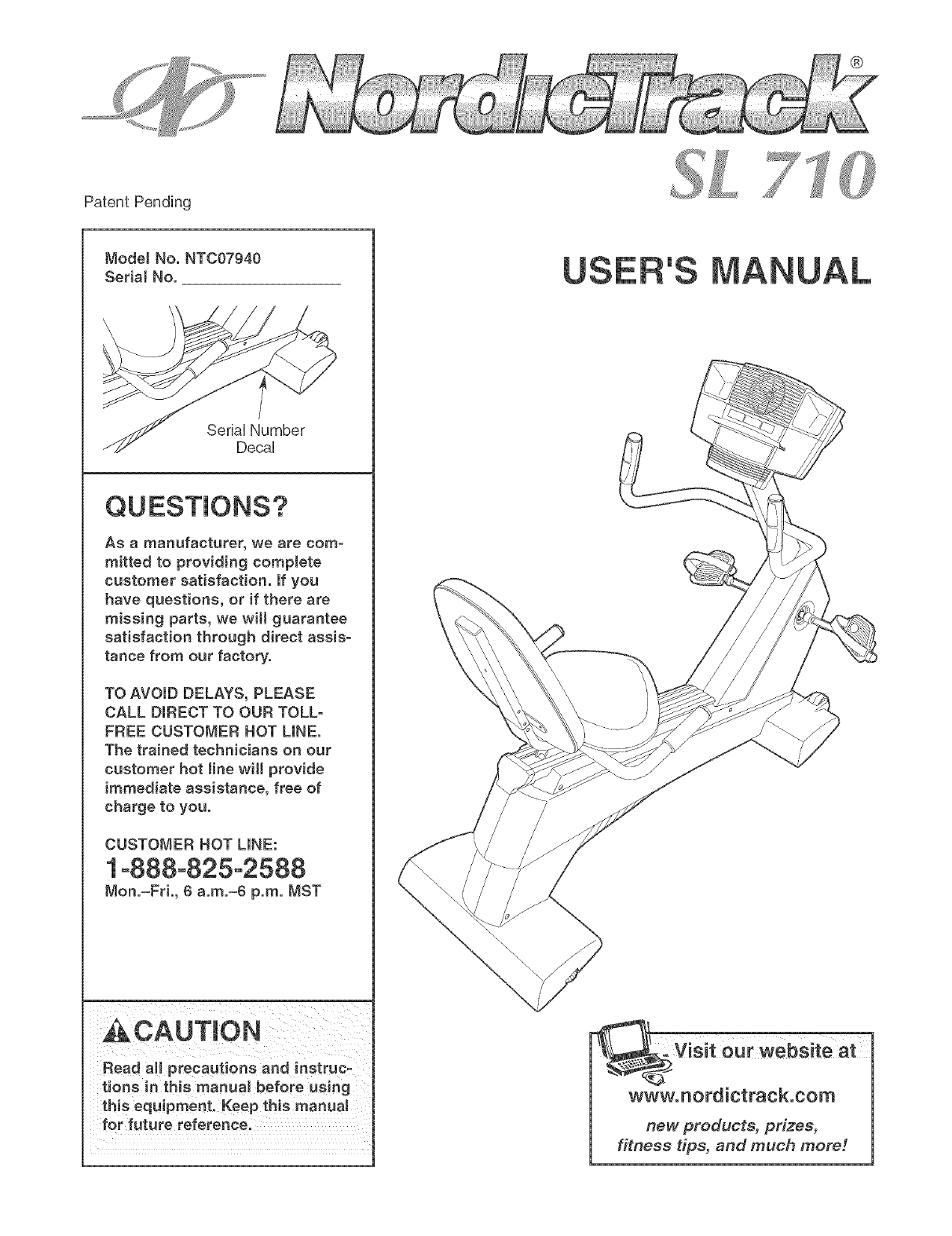
PatentPending
ModelNo.NT007940
Soda1No.
SeriaUNumber
DecaU
QUESTIONS?
As a manufacturer, we are com-
mitted to providing complete
customer satisfaction, if you
have questions, or if there are
missing parts, we wil! guarantee
satisfaction through direct assis-
tance from our factory.
TO AVOID DELAYS, PLEASE
CALL DIRECT TO OUR TOLL-
FREE CUSTOMER NOT LINE.
The trained technicians on our
customer hot line will provide
immediate assistance, free of
charge to you.
CUSTOMER HOT LINE:
1°888°825-2588
Non.=Fd., 6 a.m.=6 p.m. MST
ACAUTION
Read all precautions and instruc-
tions in this manual before using
this equipment. Keep this manual
for future reference.
US
®
:visit ourw÷bsiteat
www.nordictrack.com
new products, prizes,
fitness tips, and much more r.
®
TABLE OF CONTENTS
iMPORTANT PRECAUTIONS ................................................................ 3
BEFORE YOU BEGIN ...................................................................... 4
ASSEMBLY ............................................................................... 5
HOW TO OPERATE THE EXERCISE CYCLE ................................................... 10
MAINTENANCE AND TROUBLESHOOTING ................................................... 22
EXERCHSE GUHDELHNES ................................................................... 23
PART LiST .............................................................................. 25
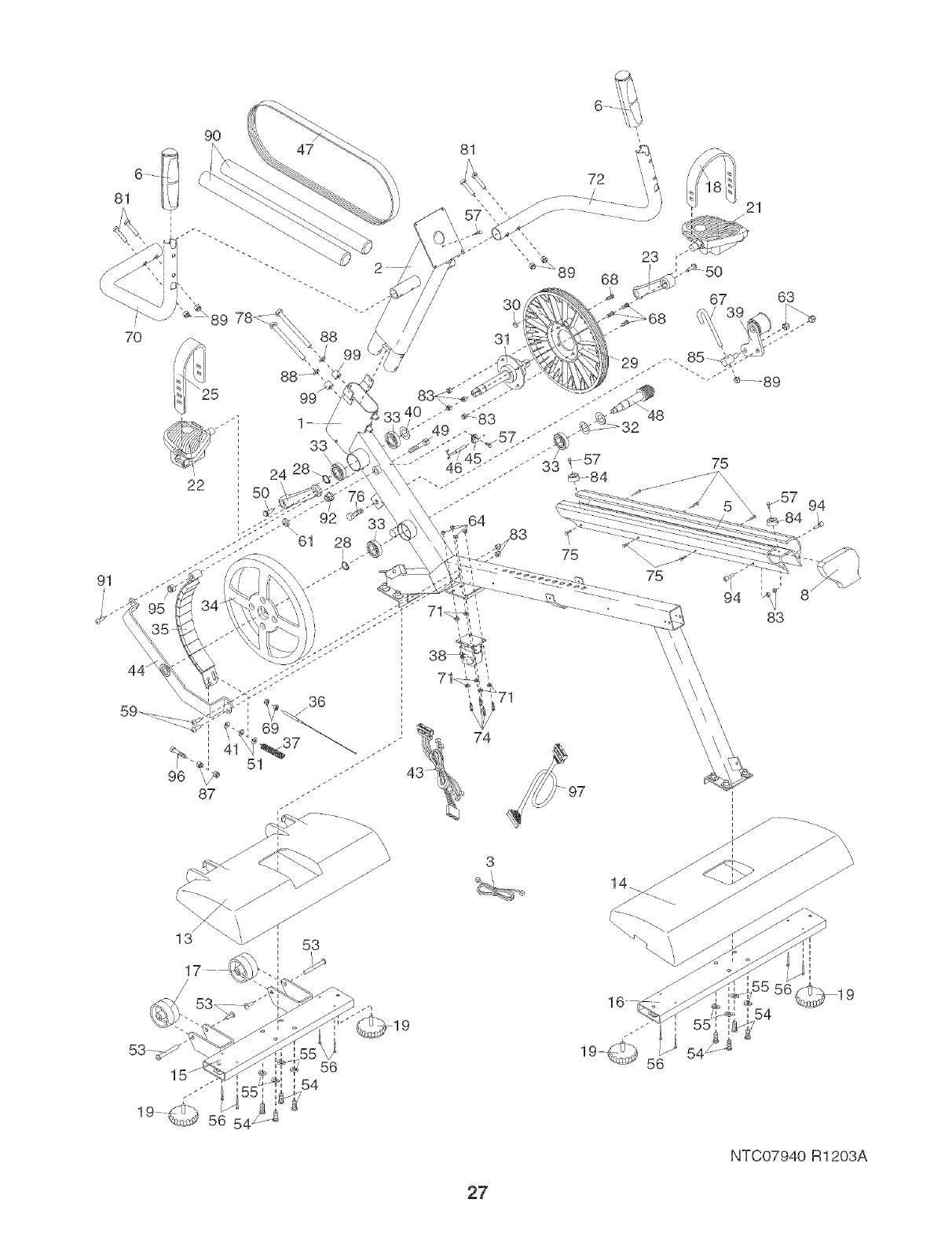
EXPLODED DRAWHNG .................................................................... 26
HOW TO ORDER REPLACEMENT PARTS ............................................. Back Cover
LiMiTED WARRANTY .............................................................. Back Cover
NordicTrack is a registered trademark of iCON Health & Fitness, inc.
2

iMPORTANT PRECAUTmONS
A WARN ING: Toreducethe.skofseriousinjury, readthefollowing important precau-
tionsbefore using the exercise cycle.
1. Read aH instructions in this manuaJ before 7. Wear euitabJe clothing when using the
using the exercise cyeJe. Use the exercise
cycle onJy as described.
2. It is the responsibility of the owner to
ensure that aH users of the e×ereise cycle
are adequately informed of all precautions.
exercise cycle; do not wear loose clothing
that couJd become caught on the e×ercise
cycle. Always wear atHetic shoes.
8. Always keep your back straight when using
the exercise cycle. Do not arch your back.
3. Use the exercise cycJe indoors on a mevel 9. if you feel pain or dizziness while e×ercia°
surface. Keep the exercise cycJe away from ing, stop immediately and cooJ down.
moisture and dust. Place a mat under the
exercise cycle to protect the floor or carpet. 10. The puJse sensor is not a medicaJ device.
Various factors, including the user's move-
4. inspect and properly tighten alJ parts regu-
larly. FlepJace any worn parts immediately.
5. Keep children under the age of 12 and pets
away from the exercise cycle at aH times.
6. The exercise cycle should not be used by
persons weighing more than 250 pounds.
ment, may affect the accuracy of heart rate
readings. The pulse sensor is intended only
as an exercise aid in determining heart rate
trends in general
11. The exercise cycle is intended for in-home
use onJy. Do not use the exercise cycle in a
commercial, rental, or institutional setting.
"_ WAR NING: Beforebeg,nn_ngthisoranyexerciseprogram,eonsultyourphysician.Th,a
is especially important for persons over the age of 35 or persons with pre-existing health problems.
Read aH instructions before using, mCONassumes no responsibility for personal injury or property
damage sustained by or through the use of this product.
3
BEFORE YOU BEGIN
Congratulations for selecting the new NordicTrack _
SL 710 exercise cycle, Cycling is one of the most
effective exercises for increasing cardiovascular fit-
ness, building endurance, and toning the entire body,
The NordicTrack _ SL 710 offers an impressive array
of features designed to let you enjoy this healthful
exercise in the comfort and privacy of your home,
For your benefit, read this manual carefully before
you use the exercise cycle, if you have questions
after reading this manual, call our Customer Service
Department toll-free at 1-888-825-2588, Monday
through Friday, 6 a,m, until 6 p,m, Mountain Time
(excluding holidays), To help us assist you, mention
the product model number and serial number when
calling, The model number is NTC07940, The serial
number can be found on a decal attached to the exer-
cise cycle (see the front cover of this manual for the
location of the decal),
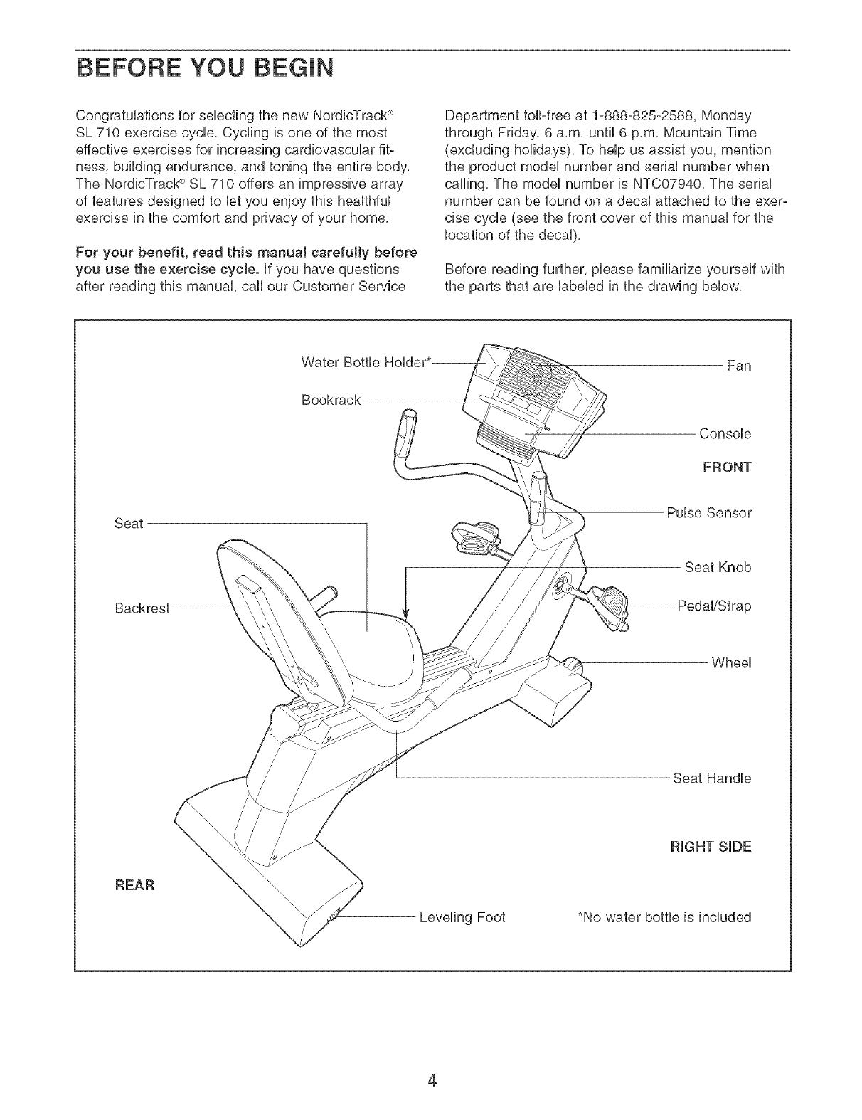
Before reading further, please familiarize yourself with
the parts that are labeled in the drawing below,
Water Bottle
Bookrack
Fan
Console
FRONT
Seat Pulse Sensor
Seat Knob
Backrest
Wheel
Seat Handle
REAR
Leveling Foot *No water bottle is included
4
ASSEMBLY
Assembly requires two persons. Hace all parts of the exercise cycle in a cbared area and remove the packing
materiab, Do not dispose of the packing materiab until assembly is compbted,
Assembly requires the included tools and your own adjustable wrench ©___./_.
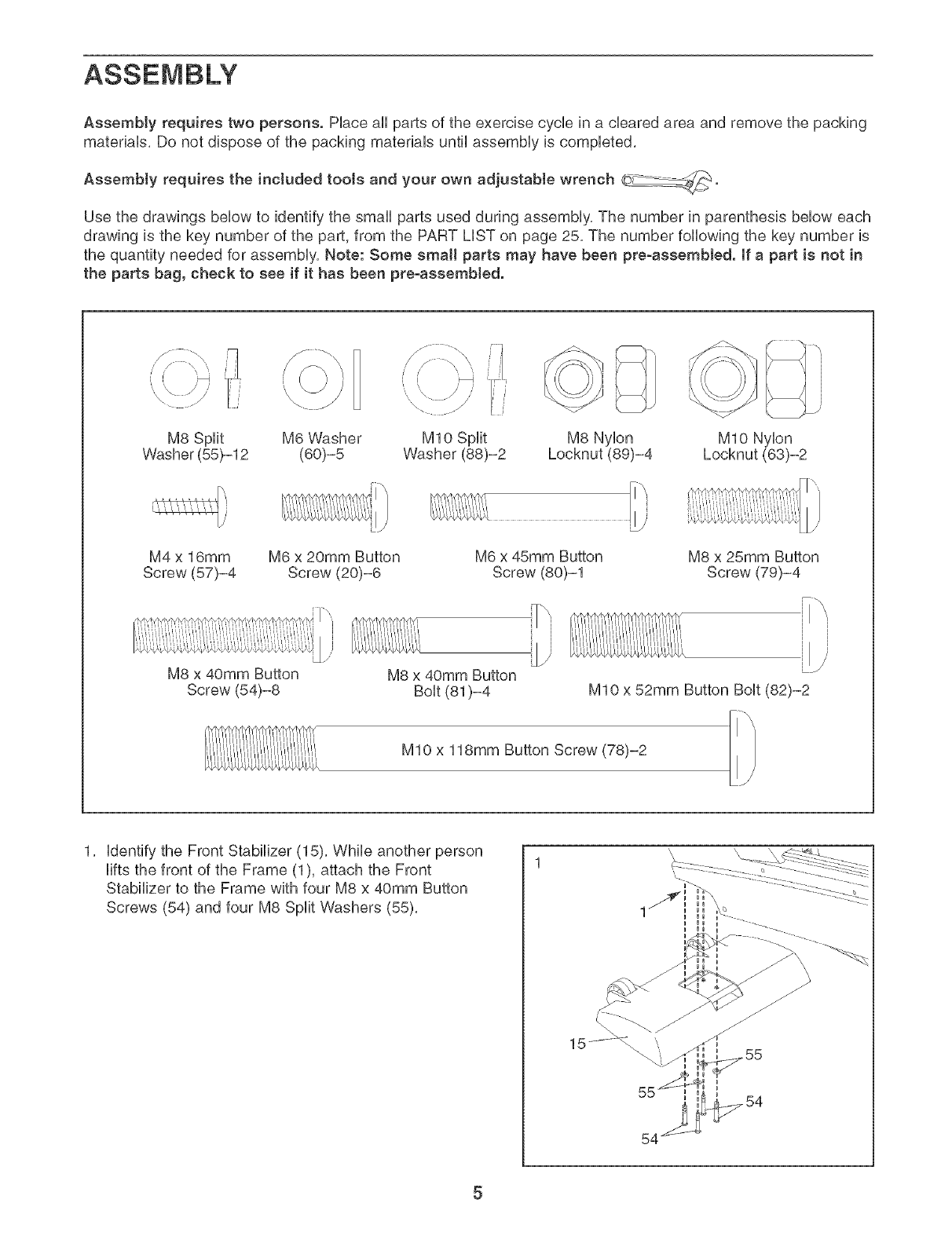
Use the drawings below to identify the small parts used during assembly, The number in parenthesis below each
drawing is the key number of the part, from the PART LiST on page 25, The number following the key number is
the quantity needed for assembly, Note: Some small parts may have been pre-assembJed. [fa part is not in
the parts bag, check to see if it has been pre-assembled.
i' I¸¸ _i
M8 Split M6 Washer M8 Nylon MIO Nylon
Washer (55)-12 (60)-5 Locknut (89)-4
M10 Split
Washer (88)-2
M4 x 16mm
Screw (57)-4
M6 x 20mm Button
Screw (20)-6
M8 x 40mm Button
Screw (54)-8
M6 x 45mm Button
Screw (80)-1
_"\]
ili
M8 x 40mm Button
Bolt (81)-4
M8 x 25mm Button
Screw (79)-4
M10 x 52mm Button Bolt (82)-2
M10 x 118mm Button Screw (78)-2
1, identify the Front Stabilizer (15), While another person
lifts the front of the Frame (1), attach the Front
Stabilizer to the Frame with four M8 x 40mm Button
Screws (54) and four M8 Split Washers (55),
5
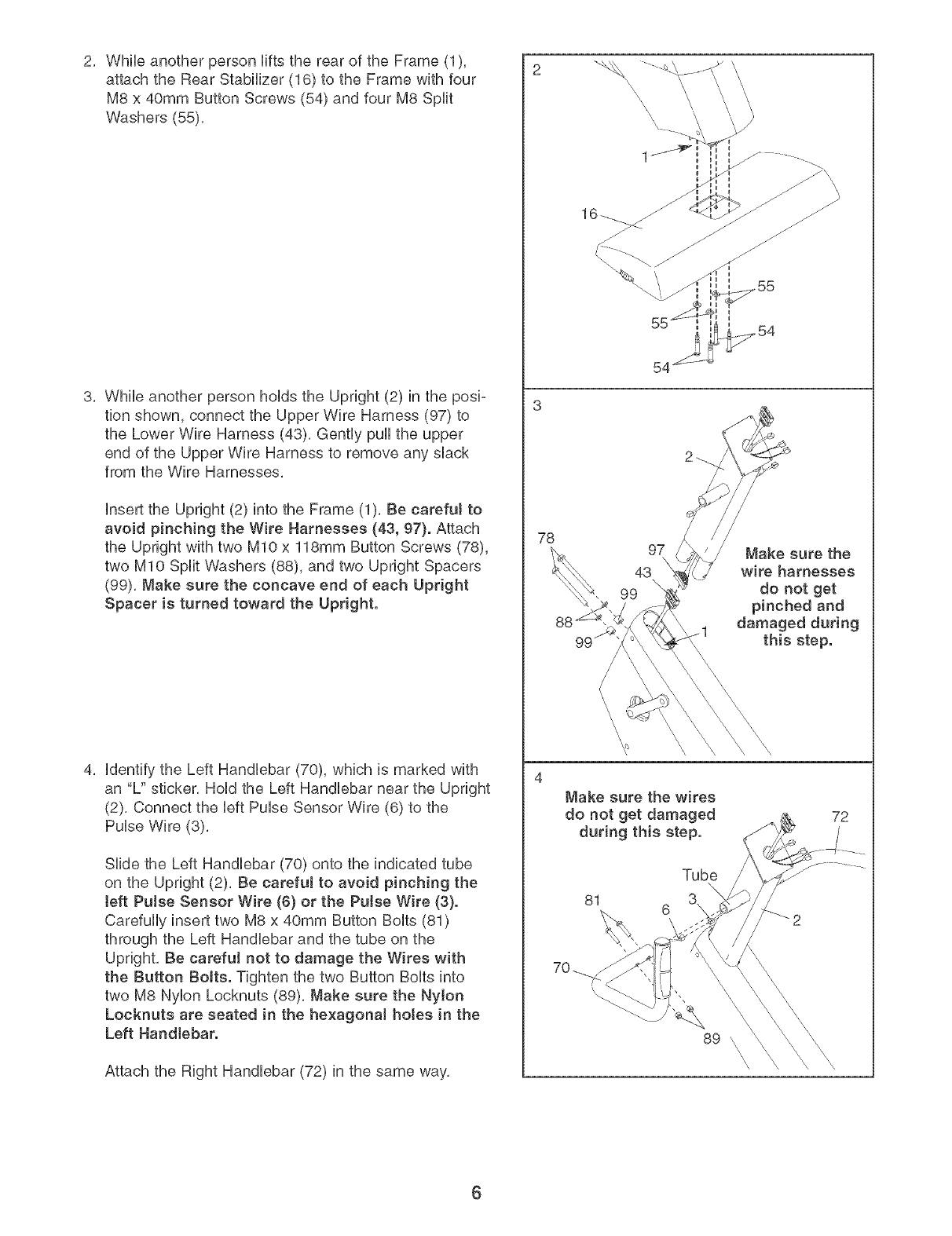
2, While another person Hfts the rear of the Frame (1),
attach the Rear Stabilizer (16) to the Frame with four
M8 x 40mm Button Screws (54) and four M8 Split
Washers (55),
3, While another person hoHdsthe Upright (2) in the posi-
tion shown, connect the Upper Wire Harness (97) to
the Lower Wire Harness (43), Gently puHHthe upper
end of the Upper Wire Harness to remove any shack
from the Wire Harnesses,
Hnsertthe Upright (2) into the Frame (1), Be carefuJ to
avoid pinching the Wire Harnesses (43, 97). Attach
the Upright with two MIO x 118mm Button Screws (78),
two MIO Split Washers (88), and two Upright Spacers
(99), Make sure the concave end of each Upright
Spacer is turned toward the Upright.
4, Hdentifythe Left HandHebar (70), which is marked with
an "U' sticker, HoHdthe Left HandHebar near the Upright
(2), Connect the HeftPuHseSensor Wire (6) to the
PuHseWire (3),
SHde the Left HandHebar (70) onto the indicated tube
on the Upright (2), Be careful to avoid pinching the
teft Pulse Sensor Wire (6} or the Pulse Wire (3}.
CarefuHHyinsert two M8 x 40mm Button BoHts(81)
through the Left HandHebar and the tube on the
Upright, Be careful not to damage the Wires with
the Button BoJts. Tighten the two Button BoHtsinto
two M8 NyHon Locknuts (89), Make sure the NyJon
Locknuts are seated in the he×agonal hotes in the
Left Handlebar.
Attach the Right Handlebar (72) in the same way,
78
\\\
54
97
43
99
Make sure the
wire harnesses
do not get
and
damaged during
this step.
Make sure the wires
do not get damaged
during this step.
Tube
81 6
72
89 \\\\\
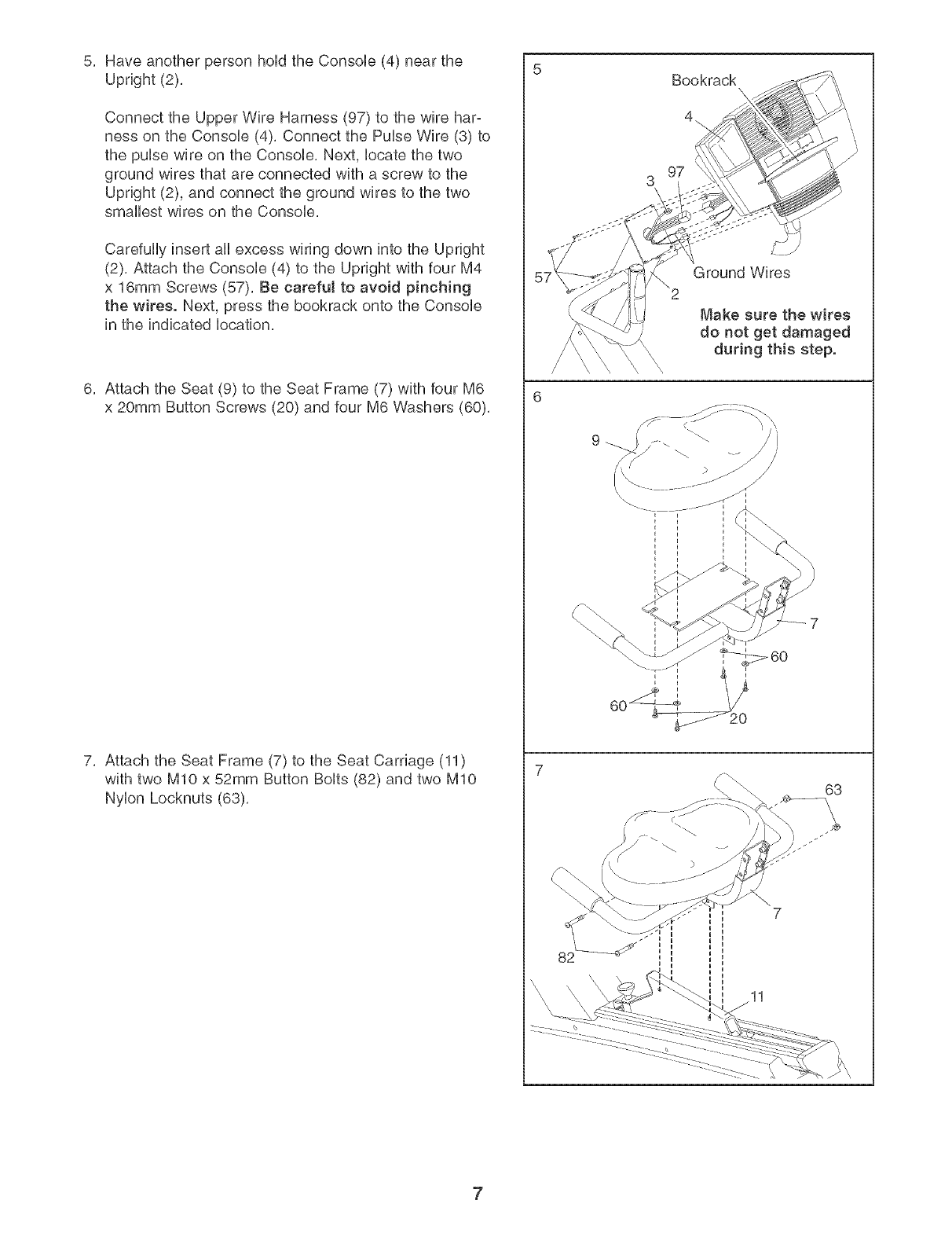
5, Have another person hoUdthe Consob (4) near the
Upright (2),
Connect the Upper Wire Harness (97) to the wire har-
ness on the Consob (4), Connect the Pube Wire (3) to
the puUsewire on the Consob, Next, bcate the two
ground wires that are connected with a screw to the
Upright (2), and connect the ground wires to the two
smallest wires on the Consob,
Carefully insert all excess wiring down into the Upright
(2), Attach the Console (4) to the Upright with four M4
x 16mm Screws (57), Be careful to avoid pinching
the wires. Next, press the bookrack onto the Console
in the indicated location,
6, Attach the Seat (9) to the Seat Frame (7) with four M6
x 20mm Button Screws (20) and four M6 Washers (60),
7, Attach the Seat Frame (7) to the Seat Carriage (11)
with two MIO x 52mm Button Bolts (82) and two MIO
Nylon Locknuts (63),
Bookrack
Ground Wires
Make sure the wires
do not get damaged
during this step.
63
7
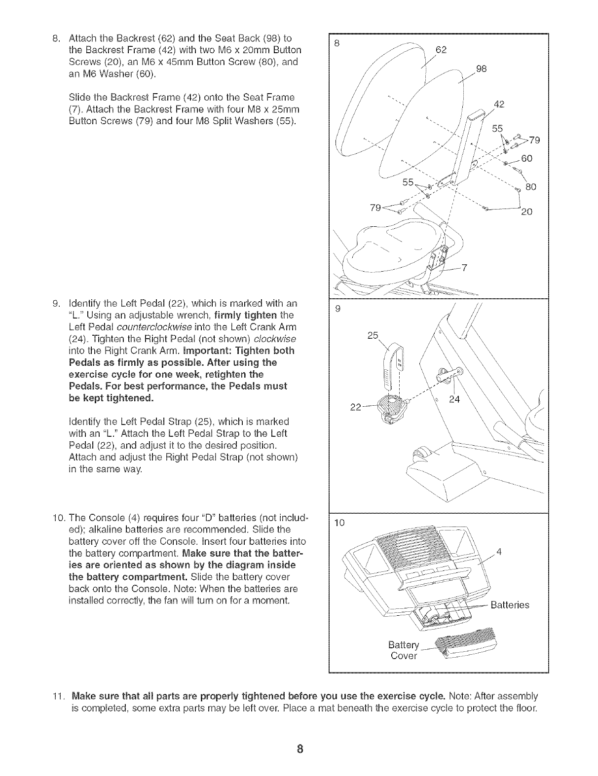
8, 8
Attach the Backrest (62) and the Seat Back (98) to
the Backrest Frame (42) with two M6 x 20mm Button
Screws (20), an M6 x 45mm Button Screw (80), and
an M6 Washer (60),
Slide the Backrest Frame (42) onto the Seat Frame
(7), Attach the Backrest Frame with four M8 x 25mm
Button Screws (79) and four M8 Split Washers (55),
9. identify the Left Pedal (22), which is marked with an
"L," Using an adjustabb wrench, firmly tighten the
Left Pedal countemlockwise into the Left Crank Arm
(24), Tighten the Right Pedal (not shown) clockwise
into the Right Crank Arm, Important: Tighten both
Pedals as firmly as possible. After using the
exercise cycle for one week, retighten the
Pedals. For best performance, the Pedals must
be kept tightened.
identify the Left Pedal Strap (25), which is marked
with an "L," Attach the Left Pedal Strap to the Left
Pedal (22), and adjust it to the desired position,
Attach and adjust the Right Pedal Strap (not shown)
in the same way,
10, The Console (4) requires four "D" batteries (not includ-
ed); alkaline batteries are recommended, Slide the
battery cover off the Console, insert four batteries into
the battery compartment, Make sure that the batter-
ies are oriented as shown by the diagram inside
the battery compartment. Slide the battery cover
back onto the Console, Note: When the batteries are
installed correctly, the fan will turn on for a moment,
10
/
62
98
/
/
42
/
55
25
Batteries
11, Make sure that aH parts are property tightened before you use the exercise cycle. Note: After assembly
is completed, some extra parts may be left over, Place a mat beneath the exercise cycle to protect the floor,
8
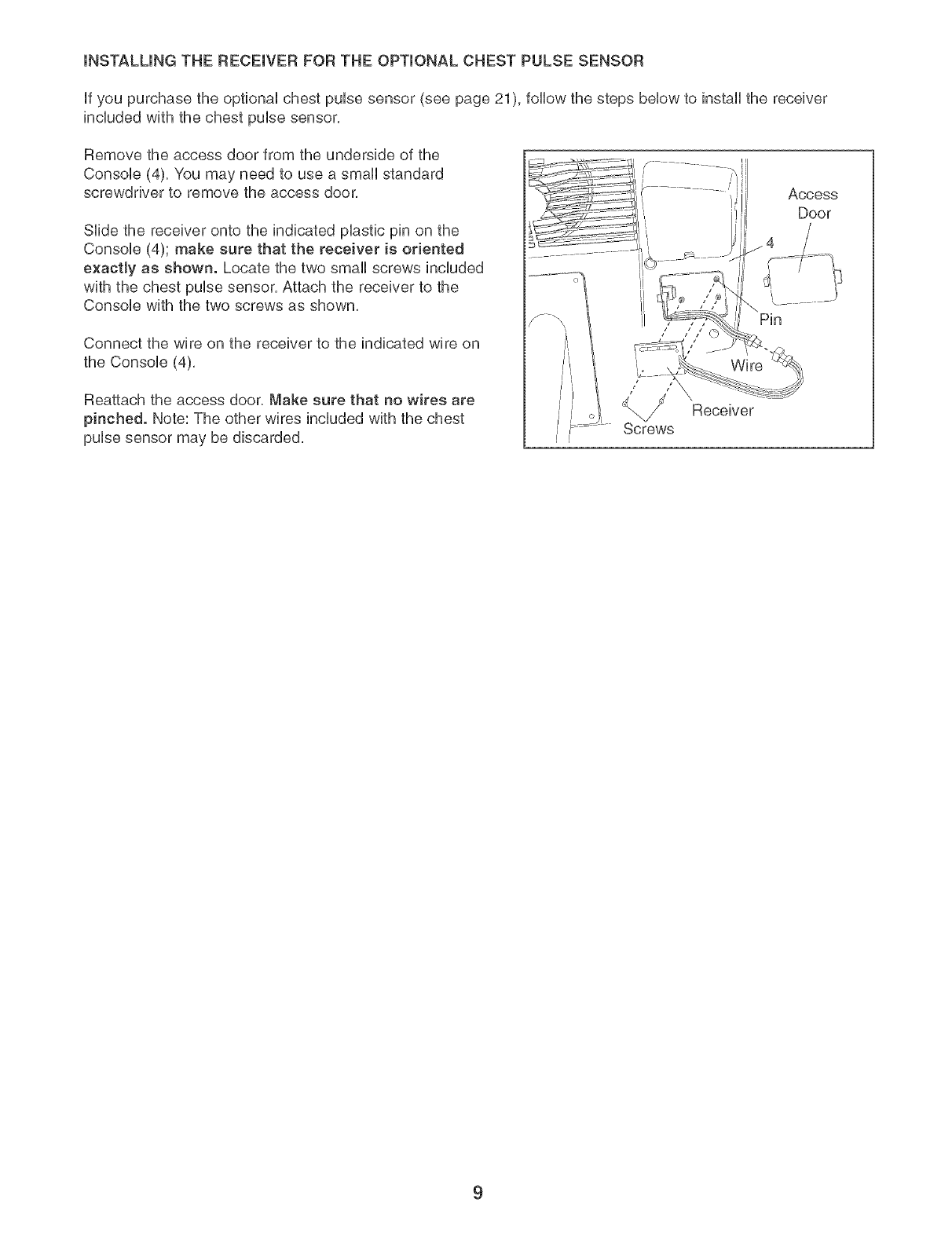
mNSTALUNG THE RECEmVER FOR THE OPTmONAL CHEST PULSE SENSOR
if you purchase the optional chest pulse sensor (see page 21), follow the steps below to install the receiver
included with the chest pulse sensor,
Remove the access door from the underside of the
Console (4). You may need to use a small standard
screwdriver to remove the access door.
Slide the receiver onto the indicated plastic pin on the
Console (4); make sure that the receiver is oriented
e×aetly as shown. Locate the two small screws included
with the chest pulse sensor. Attach the receiver to the
Console with the two screws as shown.
Connect the wire on the receiver to the indicated wire on
the Console (4),
Reattach the access door. Make sure that no wires are
pinched. Note: The other wires included with the chest
pulse sensor may be discarded.
Pin
/ 7 j
Wire
Receiver
9
HOW TO OPERATE THE EXERCISE CYCLE
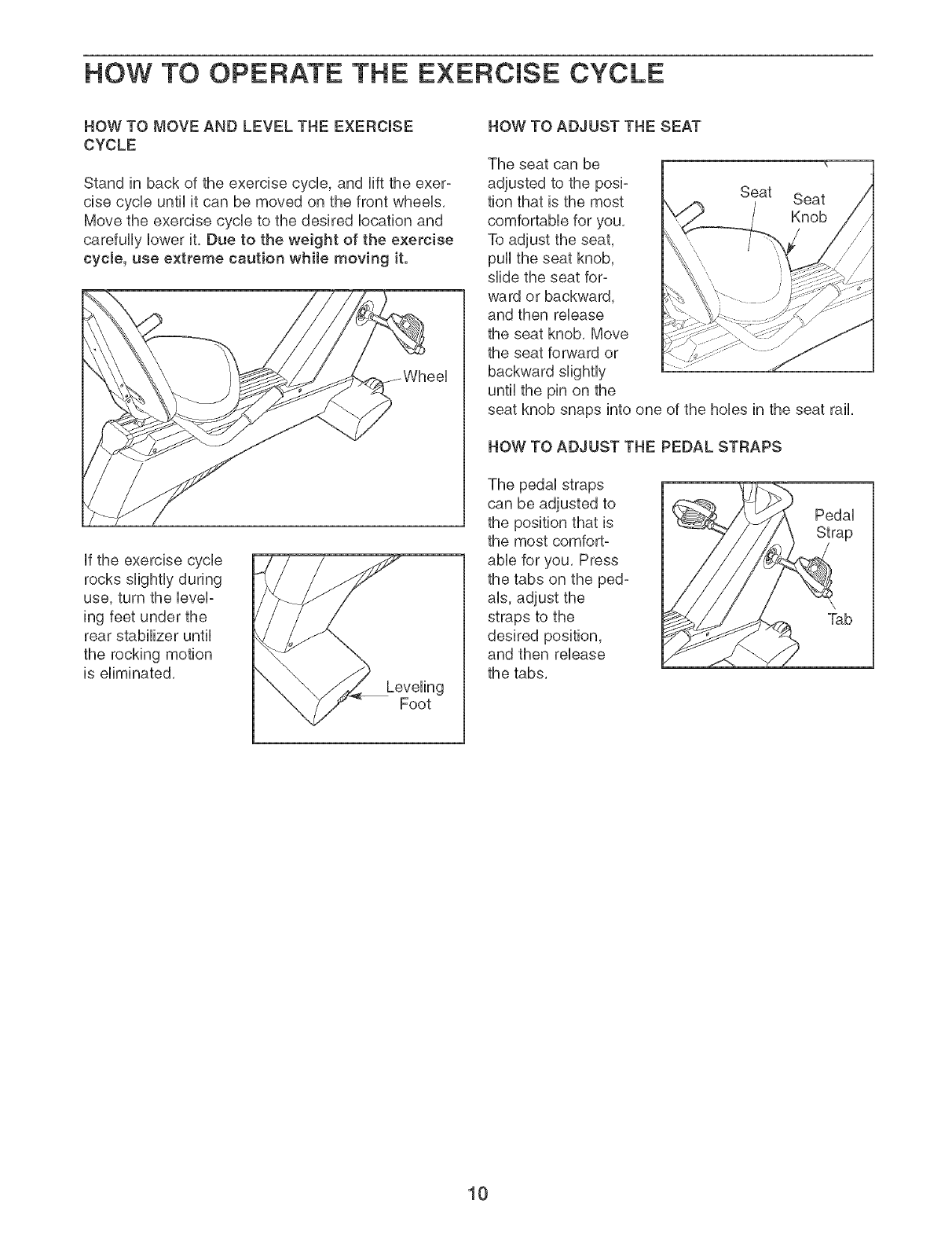
HOW TO MOVE AND LEVEL THE EXERCmSE
CYCLE
Stand in back of the exercise cycHe,and Hft the exer-
cise cycHeuntil it can be moved on the front wheeHs,
Move the exercise cycHeto the desired Hocationand
carefully lower it, Due to the weight of the exercise
cycle, use extreme caution while moving it.
if the exercise cycle
rocks slightly during
use, turn the level-
ing feet under the
rear stabilizer until
the rocking motion
is eliminated,
Foot
HOW TO ADJUST THE SEAT
The seat can be
adjusted to the posi- Seat
tion that is the most
comfortabHe for you,
To adjust the seat,
puHHthe seat knob,
slide the seat for-
ward or backward,
and then reHease
the seat knob, Move
the seat forward or
backward sHghtHy
until the pin on the
seat knob snaps into one of the holies in the seat rail,
HOW TO ADJUST THE PEDAL STRAPS
The pedaHstraps
can be adjusted to
the position that is
the most comfort°
abHefor you, Press
the tabs on the ped-
arts,adjust the
straps to the
desired position,
and then reHease
the tabs,
PedaH
ap
10
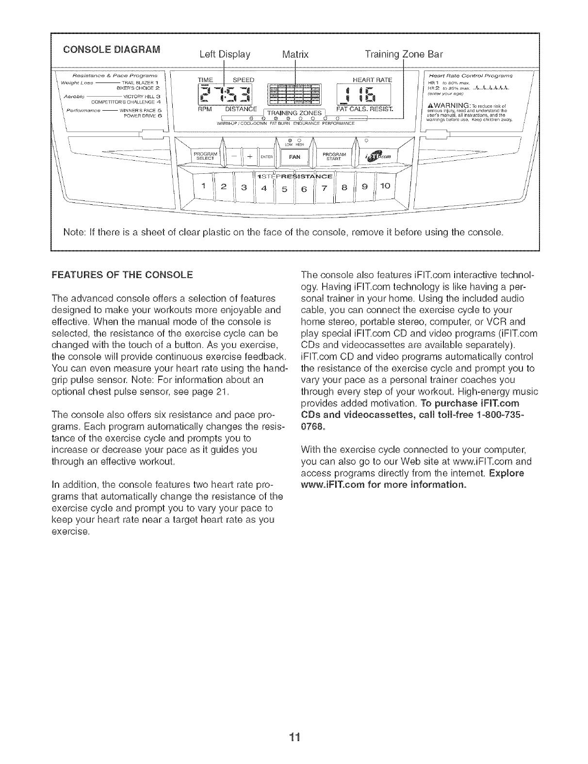
Left DispUay Matrix Training Zone Bar
I J
CONSOLE DIAGRAM
"_ Resistance & Pace Programs i
II Weight L_Jss TRAIL BLAZERI , TiME SPEED
11 AerobiG VICTORy HILL 3 :
",_ COMPETITO_'S CHALLENGE 4 /performance WINNER'S PACE 5
POWER DRIVE _ RPM DISTANCE j TRAINING ZONES
HEART RATE
FAT CALS. RESIST.
Heart Rate Cot_trol Prograt_s
HR1 to so_/o max
HR2 1o 85%ma_ J_[l_
(er,t_r your ag_
AWARNUNG : Toreduceriskof
serious mjuW, read a_ld understand the
user's manual, all inst[uct ons, arid the
FEATURES OF THE CONSOLE
The advanced consob offers a selection of features
designed to make your workouts more enjoyable and
effective, When the manual mode of the console is
selected, the resistance of the exercise cycle can be
changed with the touch of a button, As you exercise,
the console will provide continuous exercise feedback,
You can even measure your heart rate using the hand-
grip pulse sensor. Note: For information about an
optional chest pulse sensor, see page 21,
The console also offers six resistance and pace pro-
grams, Each program automatically changes the resis-
tance of the exercise cycle and prompts you to
increase or decrease your pace as it guides you
through an effective workout,
in addition, the console features two heart rate pro-
grams that automatically change the resistance of the
exercise cycle and prompt you to vary your pace to
keep your heart rate near a target heart rate as you
exercise,
The console also features iFIT,com interactive technoF
ogy, Having iFIT,com technology is like having a per-
sonal trainer in your home, Using the included audio
cable, you can connect the exercise cycle to your
home stereo, portable stereo, computer, or VCR and
play special iFIT,com CD and video programs (iFIT,com
CDs and videocassettes are available separately),
iFIT,com CD and video programs automatically control
the resistance of the exercise cycle and prompt you to
vary your pace as a personal trainer coaches you
through every step of your workout, High-energy music
provides added motivation, To purchase iFIT.com
CDs and videocassettes, call toil-free 1-800-735-
0768.
With the exercise cycle connected to your computer,
you can also go to our Web site at www, iFIT,com and
access programs directly from the intemet, Explore
wwwJFIT.com for more information.
11
HOW TO USE THE MANUAL MODE
Press any button on the consoJe or begin
peda[ing to turn on the console.
Note: The consob requires four 1.5V "D" batteries
(see assembly step 10 on page 8).
Press any button on the consob or begin pedaP
ing to turn on the consob. After a few seconds,
the consob displays will light, a tone sound, and
the consob will be ready for use.
Se[ect the manua[ mode.
When the power is
turned on, the manual
mode wiii be select-
ed, if you have
selected a program or
the iFIT,com mode,
reselect the manual
mode by pressing the Program Select button
repeatedly until a track appears in the matrix,
Begin pedaling and change the resistance of
the exercise cycle as desired.
As you pedal, change
the resistance of the
exercise cycle by
pressing the Resis-
tance buttons, There
are ten resistance
levels, Note: After the
HEART RATE
s_i
FAT CALS. RESIST.
Resistance buttons are pressed, it will take a
moment for the exercise cycle to reach the
selected resistance level.
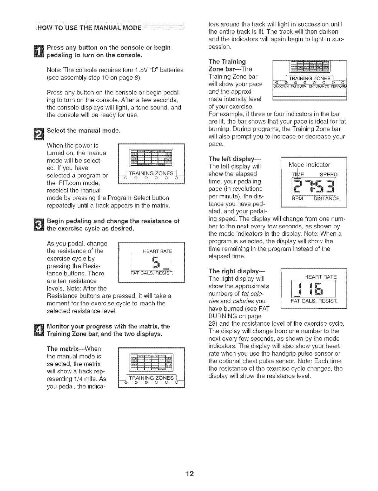
Monitor your progress with the matrix, the
Training Zone bar, and the two displays.
The matrix--When
the manual mode is
selected, the matrix
will show a track rep-
resenting 1/4 mile. As
you pedal, the indica-
tots around the track wiii light in succession until
the entire track is lit, The track wiii then darken
and the indicators wiii again begin to light in suc-
cession,
The Training
Zone bar--The
Training Zone bar
wiii show your pace
and the approxi-
mate intensity level
of your exercise,
For example, if three or four indicators in the bar
are lit, the bar shows that your pace is ideal for fat
burning, During programs, the Training Zone bar
wiii also prompt you to increase or decrease your
pace,
The left display--
The left display wiii
show the elapsed
time, your pedaling
pace (in revolutions
per minute), the dis-
tance you have ped-
aled, and your pedal-
Mode indicator
T_E SPEED
-t.c
RPM D_STANOE
ing speed, The display wiii change from one num-
ber to the next every few seconds, as shown by
the mode indicators in the display, Note: When a
program is selected, the display will show the
time remaining in the program instead of the
elapsed time,
The right display--
The right display wili
numbers of fat ca/o°
ties and calories you
have burned (see FAT
BURNING on page
HEART RATE
m
FAT CALS. RESIST.
23) and the resistance level of the exercise cycle,
The display will change from one number to the
next every few seconds, as shown by the mode
indicators, The display wiii also show your heart
rate when you use the handgrip pulse sensor or
the optional chest pulse sensor, Note: Each time
the resistance of the exercise cycle changes, the
display will show the resistance level,
12
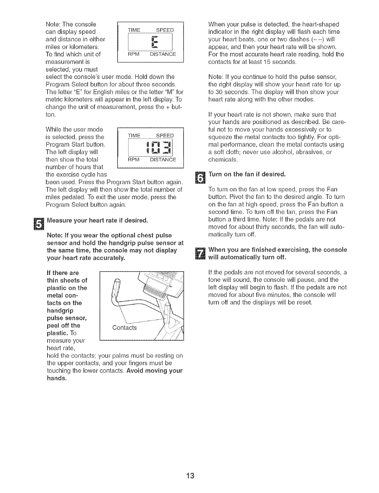
Note: The console
can display speed
and distance in either
miles or kilometers,
To find which unit of
measurement is
selected, you must
TIME SPEED
I °C
RPM D_STANCE
sebct the console's user mode, Hold down the
Program Select button for about three seconds,
The letter "E" for English miles or the letter "M" for
metric kilometers will appear in the left display, To
change the unit of measurement, press the + but-
ton,
While the user mode
is selected, press the
Program Start button,
The left display will
then show the total
number of hours that
the exercise cycle has
TIME SPEED
tPl_d 1
RPM D_STANCE
been used, Press the Program Start button again,
The left display wiii then show the total number of
miles pedaled, To exit the user mode, press the
Program Select button again,
Measure your heart rate if desired,
Note: if you wear the optional chest puJse
sensor and hold the handgrip pulse sensor at
the same time, the console may not display
your heart rate accurately,
If there are
thin sheets of
plastic on the
rnetaJ con-
tacts on the
handgdp
putse sensor,
peel off the
plastic. To
measure your
heart rate,
Contacts /
hold the contacts; your palms must be resting on
the upper contacts, and your fingers must be
touching the lower contacts, Avoid moving your
hands,
When your pulse is detected, the heart-shaped
indicator in the right display wiii flash each time
your heart beats, one or two dashes (- -) will
appear, and then your heart rate will be shown,
For the most accurate heart rate reading, hold the
contacts for at bast 15 seconds,
Note: if you continue to hold the pulse sensor,
the right display wiii show your heart rate for up
to 30 seconds, The display wiii then show your
heart rate along with the other modes,
if your heart rate is not shown, make sure that
your hands are positioned as described, Be care°
ful not to move your hands excessively or to
squeeze the metal contacts too tightly, For opti-
mal performance, clean the metal contacts using
a soft cloth; never use alcohol, abrasives, or
chemicals,
Turn on the fan if desired,
To turn on the fan at low speed, press the Fan
button, Pivot the fan to the desired angle, To turn
on the fan at high speed, press the Fan button a
second time, To turn off the fan, press the Fan
button a third time, Note: if the pedals are not
moved for about thirty seconds, the fan will auto°
matically turn off,
When you are finished exercising, the console
wilt autornaticaHy turn off,
if the pedals are not moved for several seconds, a
tone will sound, the console will pause, and the
left display wiii begin to flash, if the pedals are not
moved for about five minutes, the console will
turn off and the displays will be reset,
13
HOW TO USE RESBTANCE AND PACE
PROGRAMS
Press any button on the consob or begin
pedaling to turn on the consob.
See step 1 on page 12.
Sebct one of the six resistance and pace
programs.
When the power is
turned on, the man-
ual mode will be
sebcted. To select a
resistance and pace
program, press the
Program Select but-
HEART RATE
FAT CALS. RESBT.
ton repeatedUy until a '9 1," '9 2," '9 3," "P 4/
'9 5/or "P 6" appears in the right disphy.
Each program is divided into several time seg-
ments of different lengths, One resistance setting
and one pace setting are programmed for each
segment, (Note: The same resistance setting
and/or pace setting may be programmed for two or
more consecutive segments,) The resistance set-
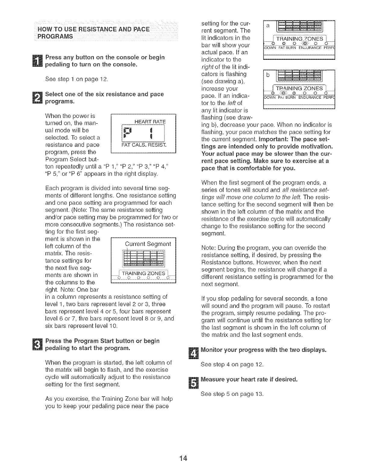
ting for the first seg-
ment is shown in the
left column of the Current Segment
matrix, The resis-
tance settings for
the next five seg-
ments are shown in [-TRAmN[NGZONES'J
0 O o 0 0
the columns to the
right. Note: One bar
in a column represents a resistance setting of
level 1, two bars represent level 2 or 3, three
bars represent level 4 or 5, four bars represent
level 6 or 7, five bars represent level 8 or 9, and
six bars represent level 10.
Press the Program Start button or begin
pedaling to start the program.
When the program is started, the left column of
the matrix wiii begin to flash, and the exercise
cycle will automatically adjust to the resistance
setting for the first segment,
As you exercise, the Training Zone bar wiii help
you to keep your pedaling pace near the pace
setting for the cur-
rent segment, The
lit indicators in the TRAmNmNG7ONES
bar will show your ® o _£
FAT BURN FNudRANCE PERF
actual pace. if an
indicator to the
right of the lit indi-
cators is flashing
(see drawing a),
increase your
pace, if an indica- ® o o
ENDURANCE
tot to the left of
any lit indicator is
flashing (see draw-
ing b), decrease your pace, When no indicator is
flashing, your pace matches the pace setting for
the current segment, important: The pace set-
tings are intended only to provide motivation.
Your actuat pace may be slower than the cur-
rent pace setting. Make sure to exercise at a
pace that is comfortabJe for you.
When the first segment of the program ends, a
series of tones wiii sound and all resistance set-
tings wif/ move one column to the left, The resis-
tance setting for the second segment will then be
shown in the left column of the matrix and the
resistance of the exercise cycle will automatically
change to the resistance setting for the second
segment.
Note: During the program, you can override the
resistance setting, if desired, by pressing the
Resistance buttons, However, when the next
segment begins, the resistance will change if a
different resistance setting is programmed for the
next segment,
if you stop pedaling for several seconds, a tone
wiii sound and the program wiii pause, To restart
the program, simply resume pedaling, The pro-
gram will continue until the resistance setting for
the last segment is shown in the left column of
the matrix and the last segment ends,
Monitor your progress with the two displays.
See step 4 on page 12.
Measure your heart rate if desired.
See step 5 on page 13.
14
Turn on the fan if desired.
See step 6 on page 13,
When the program is finished, the console
wilt automatically turn off.
See step 7 on page 13,
HOWTOUSE HEART RATE PROGRAMS
Each heart rate program heUpsyou to keep your heart
rate near a certain percentage of your maximum heart
rate during your workout, ('Your maximum heart rate is
estimated by subtracting your age from 220, For
exampb, if you are 30 years cud, your maximum heart
rate is 190,) Heart rate program 1 is designed to keep
your heart rate between 50% and 80% of your maxi-
mum heart rate while you exercise; heart rate pro-
gram 2 is designed to keep your heart rate between
50% and 85% of your maximum heart rate,
Follow the steps bebw to use a heart rate program,
Press any button on the consoJe or begin
pedaling to turn on the console.
See step 1 on page 12,
Select one of the heart rate programs.
When the power is
turned on, the manu-
al mode wiii be
selected, To select a
heart rate program,
press the Program
Select button repeat-
HEART RATE
o..! ,
FAT CALS. RESIST,
edly until an "H 1" or "H 2" appears in the right
display,
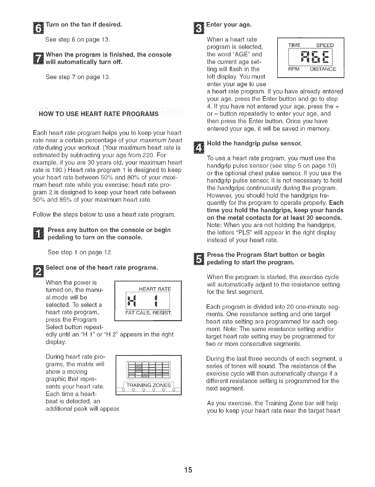
During heart rate pro-
grams, the matrix wiii
show a moving
graphic that repre-
sents your heart rate,
Each time a heart-
beat is detected, an
additional peak will appear,
Enter your age.
When a heart rate
program is selected,
the word "AGE" and
the current age set-
ting will flash in the
left display, You must
enter your age to use
a heart rate program, if you have already entered
your age, press the Enter button and go to step
4, if you have not entered your age, press the +
or - button repeatedly to enter your age, and
then press the Enter button, Once you have
entered your age, it will be saved in memory,
T_ME SPEED
CI E
RPM D_STANCE
Hold the handgrip putse sensor.
To use a heart rate program, you must use the
handgrip pulse sensor (see step 5 on page 10)
or the optional chest pulse sensor, if you use the
handgrip pulse sensor, it is not necessary to hold
the handgrips continuously during the program,
However, you should hold the handgrips fie-
quently for the program to operate properly, Each
time you hoM the handgrips, keep your hands
on the metal contacts for at Jeast 30 seconds.
Note: When you are not holding the handgrips,
the letters "PLS" will appear in the right display
instead of your heart rate,
Press the Program Start button or begin
pedaling to start the program.
When the program is started, the exercise cycle
wiii automatically adjust to the resistance setting
for the first segment,
Each program is divided into 20 one-minute seg-
ments, One resistance setting and one target
heart rate setting are programmed for each seg-
ment, Note: The same resistance setting and/or
target heart rate setting may be programmed for
two or more consecutive segments,
During the last three seconds of each segment, a
series of tones will sound, The resistance of the
exercise cycle will then automatically change if a
different resistance setting is programmed for the
next segment,
As you exercise, the Training Zone bar will help
you to keep your heart rate near the target heart
15
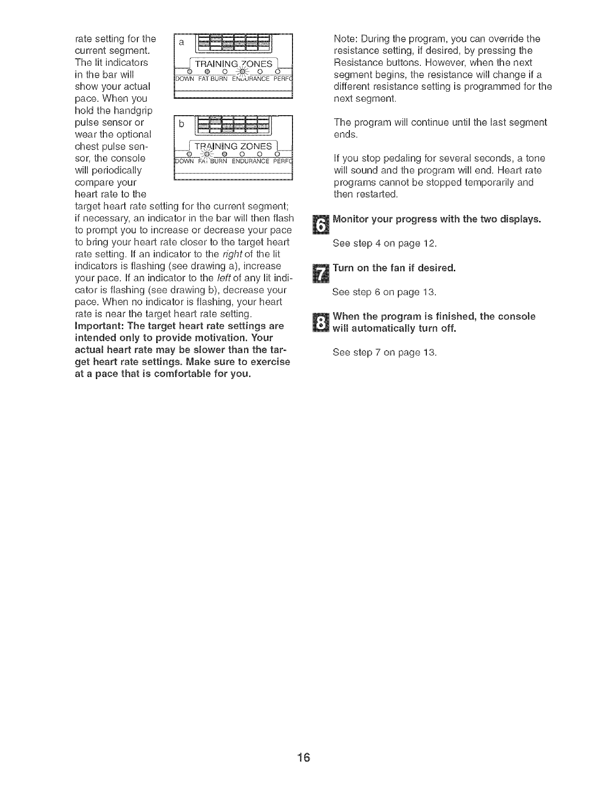
rate setting for the
current segment,
The Htindicators TRAINING ZONES
in the bar wHU F--_BU--_NE_xNP-_:--
show your actuaU
pace, When you
hoUdthe handgrip
pube sensor or
wear the optionaU
chest puUsesen-
sor, the consob e o o
ENDURANCE
wHUperiodbaHy
compare your
heart rate to the
target heart rate setting for the current segment;
if necessary, an indicator in the bar wHUthen flash
to prompt you to increase or decrease your pace
to bring your heart rate closer to the target heart
rate setting, ff an indicator to the rightof the Ht
indicators is flashing (see drawing a), increase
your pace, ff an indicator to the leftof any Htindi-
cator is flashing (see drawing b), decrease your
pace, When no indicator is flashing, your heart
rate is near the target heart rate setting,
Important: The target heart rate settings are
intended only to provide motivation. Your
actuaJ heart rate may be slower than the tar-
get heart rate settings. Make sure to exercise
at a pace that is comfortable for you.
Note: During the program, you can override the
resistance setting, if desired, by pressing the
Resistance buttons, However, when the next
segment begins, the resistance will change if a
different resistance setting is programmed for the
next segment,
The program wili continue until the last segment
ends,
if you stop pedaling for several seconds, a tone
will sound and the program will end, Heart rate
programs cannot be stopped temporarily and
then restarted,
Monitor your progress with the two displays.
See step 4 on page 12,
Turn on the fan if desired.
See step 6 on page 13,
When the program is finished, the consote
wilt automatically turn off.
See step 7 on page 13,
16
HOW TO CONNECT YOUR CD PLAYER, VCR,
OR COMPUTER
To use iFIT.com CDs, the exercise cycb must be con-
nected to your portaMe CD pUayer,portable stereo,
home stereo, or computer with CD pUayer,See pages
17 and 18 for connecting instructions, To use iFIT.com
videocassettes, the exercise cycle must be connected
to your VCR, See page 19 for connecting instructions,
To use iFIT.com programs directly from our Web
site, the exercise cycb must be connected to your
home computer, See page 18 for connecting instruc-
tions,
HOW TO CONNECT YOUR PORTABLE CD PLAYER
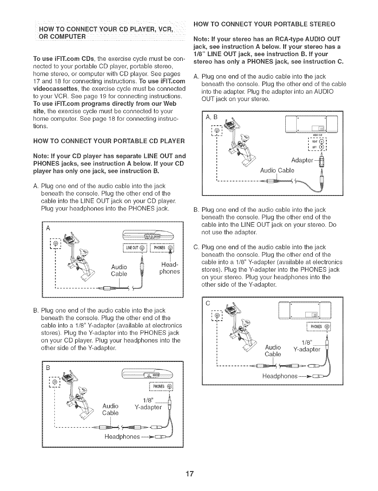
Note: If your CD player has separate LINE OUT and
PHONES jacks, see instruction A beJow. If your CD
player has only one jack, see instruction B.
A. Hug one end of the audio came into the jack
beneath the consob. Hug the other end of the
came into the MNE OUTjack on your CD player,
Hug your headphones into the PHONES jack.
HOW TO CONNECT YOUR PORTABLE STEREO
Note: If your stereo has an RCA-type AUDIO OUT
jack, see instruction A betow. If your stereo has a
1/8" LINE OUT jack, see instruction B. If your
stereo has only a PHONES jack, see instruction C.
A, Hug one end of the audio cabUeinto the jack
beneath the consob, Hug the other end of the cable
into the adapter, Plug the adapter into an AUDIO
OUT jack on your stereo,
AUDIOOUT
i[_T 1
L = = = I
B,
C,
Plug one end of the audio cable into the jack
beneath the console. Plug the other end of the
cable into the LINE OUT jack on your stereo. Do
not use the adapter.
Plug one end of the audio cable into the jack
beneath the console, Plug the other end of the
cable into a 1/8" Y-adapter (available at electronics
stores), Plug the Y-adapter into the PHONES jack
on your stereo, Plug your headphones into the
other side of the Y-adapter,
B, Plug one end of the audio cable into the jack
beneath the console, Plug the other end of the
cable into a 1/8" Y-adapter (available at electronics
stores), Plug the Y-adapter into the PHONES jack
on your CD player, Plug your headphones into the
other side of the Y-adapter,
C
[===_
,B
i pHoNEs®i
17
HOW TO CONNECT YOUR HOME STEREO HOW TO CONNECT YOUR COMPUTER
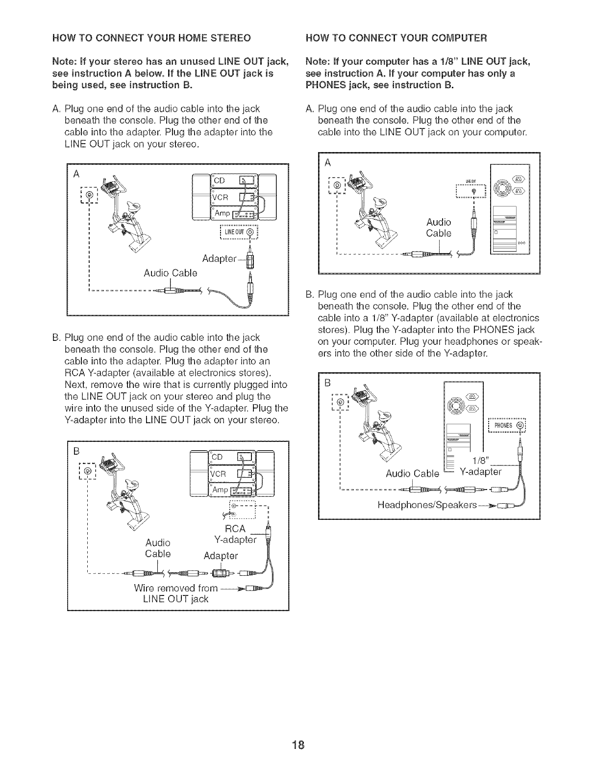
Note: If your stereo has an unused LINE OUT jack,
see instruction A below, mfthe LmNEOUT jack is
being used, see instruction B.
A, Hug one end of the audio cane into the jack
beneath the console, Hug the other end of the
cane into the adapter, Hug the adapter into the
LiNE OUT jack on your stereo,
i UNEOUT@ i
u
Audio CaMe %__._
u .............
B, Hug one end of the audio cane into the jack
beneath the console, Hug the other end of the
came into the adapter, Hug the adapter into an
RCA Y-adapter (avNHabHeat eHectroNcs stores),
Next, remove the wire that is currently piugged into
the LiNE OUT jack on your stereo and piug the
wire into the unused side of the Y-adapter, Hug the
Y-adapter into the LiNE OUT jack on your stereo,
RCA
Audio Y-adapter
CaNe Adapter
Wire removed from
LiNE OUT jack
Note: If your computer has a 1/8" LINE OUT jack,
see instruction A. mfyour computer has only a
PHONES jack, see instruction B.
A, Hug one end of the audio cane into the jack
beneath the console, Hug the other end of the
came into the LiNE OUT jack on your computer,
A
i CabUe
_dCT@ _
i
=
=1 cx_
B, Hug one end of the audio cane into the jack
beneath the console, Hug the other end of the
came into a 1/8" Y-adapter (availabie at electronics
stores), Hug the Y-adapter into the PHONES jack
on your computer, Hug your headphones or speak-
ers into the other side of the Y-adapter,
Audio CaNe
i pHoNEs®i
= 1/8"
Y-adapter
Head phon es/Speake rs _E:3:::_
18
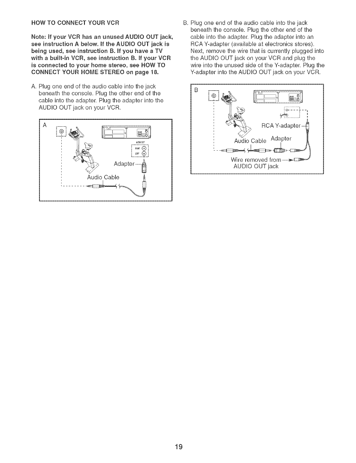
HOW TO CONNECT YOUR VCR
Note: if your VCR has an unused AUDIO OUT jack,
see instruction A below, if the AUDIO OUT jack is
being used, see instruction B. mfyou have a TV
with a buitt-in VCR, see instruction B. ff your VCR
is connected to your home stereo, see NOW TO
CONNECT YOUR HOME STEREO on page 18.
A, Hug one end of the audio cabUeinto the jack
beneath the consoUe, Hug the other end of the
came into the adapter, Hug the adapter into the
AUDUO OUT jack on your VCR,
A
i-----i J .......
.
.........
B, Hug one end of the audio cabUe into the jack
beneath the consoUe, Hug the other end of the
came into the adapter, Hug the adapter into an
RCA Y-adapter (avaHaMe at eUectronics stores),
Next, remove the wire that is currently pUugged into
the AUDUO OUT jack on your VCR and pUugthe
wire into the unused side of the Y-adapter, Plug the
Y-adapter into the AUDIO OUT jack on your VCR,
:°£°i __._ RCA Y-ada
Audio Cable Adapter
Wire removed from
AUDIO OUT jack
19
HOWTO USE mFmT.COMCD AND VmDEO
PROGRAMS
To use iFUT,com CDs or videocassettes, the exercise
cycle must be connected to your portaMe CD pUayer,
portabb stereo, home stereo, computer with CD pUay-
er, or VCR, See HOW TO CONNECT YOUR CD
PLAYER, VCR, OR COMPUTER on page 17, To pur-
chase iFIT.com CDs and videocassettes, call toll-
free 1-800-735-0768.
Follow the steps bebw to use an iFF, com CD or
video program,
Begin pedaling to activate the console.
See step 1 on page 12,
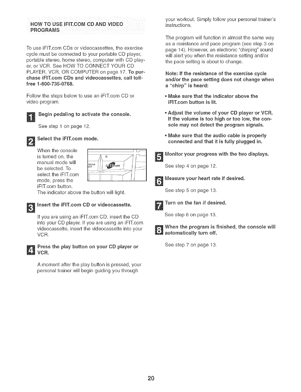
Select the iFIT.com mode.
When the consob
is turned on, the
manuaU mode wHU
be sebcted, To
sebct the iFF, com
mode, press the
iFUT,com button,
The indicator above the button wHUHght,
Insert the iFIT.com CD or videocassette.
if you are using an iFUT,com CD, insert the CD
into your CD player, If you are using an iFIT,com
videocassette, insert the videocassette into your
VCR,
Press the play button on your CD player or
VCR.
A moment after the play button is pressed, your
personal trainer wiii begin guiding you through
your workout, Simply follow your personal trainer's
instructions,
The program wiii function in almost the same way
as a resistance and pace program (see step 3 on
page 14), However, an electronic "chirping" sound
will alert you when the resistance setting and/or
the pace setting is about to change,
Note: If the resistance of the exercise cycJe
and/or the pace setting does not change when
a "chirp" is heard:
Make sure that the indicator above the
iFIT.com button is tit.
* Adjust the voJume of your CO player or VCR.
If the volume is too high or too low, the con-
sote may not detect the program signaJs.
Make sure that the audio came is properly
connected and that it is fully plugged in.
Monitor your progress with the two displays.
See step 4 on page 12,
Measure your heart rate if desired.
See step 5 on page 13,
Turn on the fan if desired.
See step 6 on page 13,
When the program is finished, the consote wilt
automatically turn off.
See step 7 on page 13,
2O
HOW TO USE PROGRAMS DIRECTLY FROM
OUR WEB StaTE
Our Web site at www, iFIT,com allows you to play
iFIT,com audio and video programs directly from the
internet, To use programs from our Web site, the exer-
cise cycle must be connected to your home computer,
See HOW TO CONNECT YOUR COMPUTER on
page 18, in addition, you must have an intemet con-
nection and an internet service provider, A list of spe-
cific system requirements wiii be found on our Web
site,
Follow the steps below to use a program from our
Web site,
Begin pedaling to activate the console.
See step 1 on page 12,
Select the iFlT.com mode.
When the console
is turned on, the ®
manual mode wiii ._
be selected, To
select the iFIT,com
mode, press the
iFIT,com button,
The indicator above the button will light,
Go to your computer and start an internet
connection.
Start your Web browser, if necessary, and go
to our Web site at wwwJFlT.com.
Foltow the desired links on our Web site to
select a program.
Read and follow the on-line instructions for using
a program,
Follow the on-line instructions to start the
program.
When you start the program, an on-screen count-
down will begin,
Return to the exercise cycle and begin
pedaling.
When the on-screen countdown ends, the pro-
gram wiii begin, The program wiii function in
almost the same way as a resistance and pace
program (see step 8 on page 14), However, an
electronic "chirping" sound wiii alert you when the
resistance setting and/or the pace setting is about
to change,
Monitor your progress with the two displays.
See step 4 on page 12,
Measure your heart rate if desired.
See step 5 on page 13,
Turn on the fan if desired.
See step 6 on page 13,
When you are finished exercising, the console
wilt automatically turn off.
See step 7 on page 13,
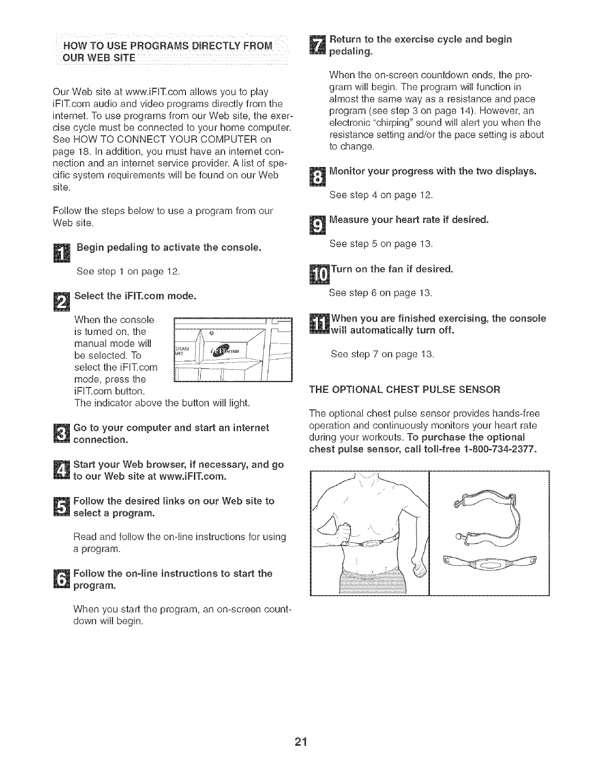
THE OPTIONAL CHEST PULSE SENSOR
The optional chest pulse sensor provides hands-free
operation and continuously monitors your heart rate
during your workouts, To purchase the optional
chest pulse sensor, call toil-free 1-800-734-2377.
21
MAINTENANCE AND TROUBLESHOOTING
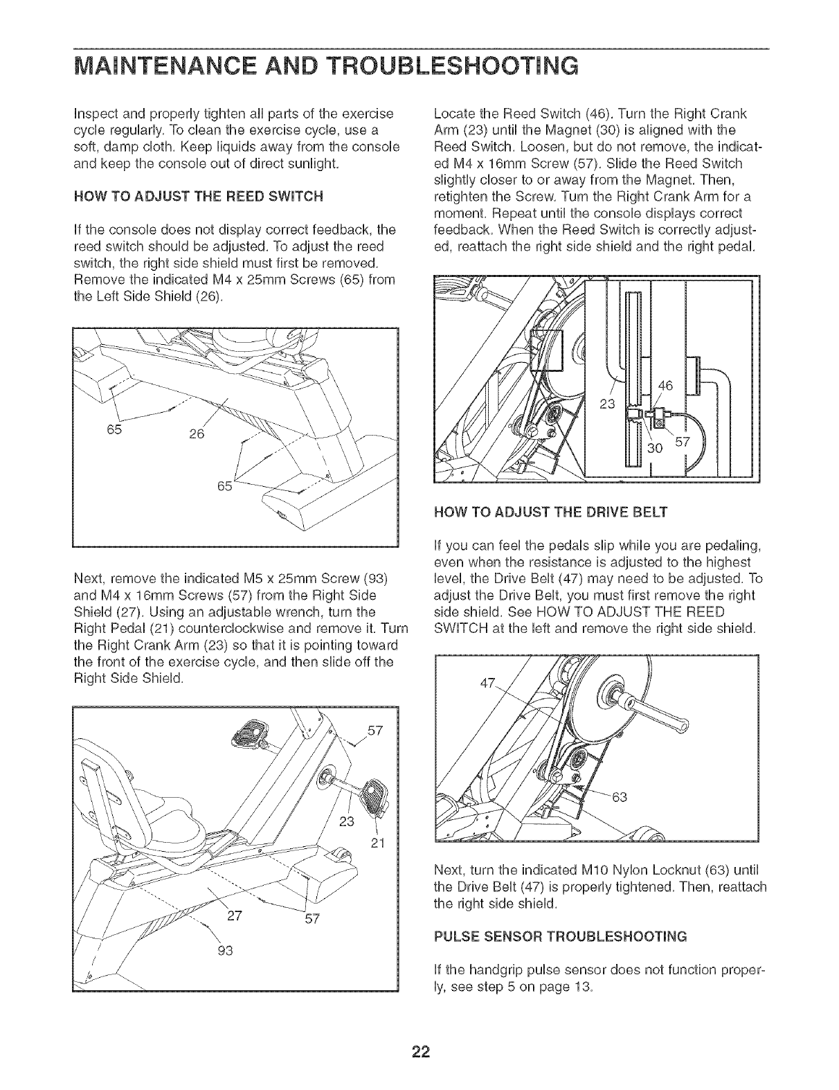
Unspect and properUy tighten aH parts of the exercise
cycle reguUarUy,To dean the exercise cycUe, use a
soft, damp cloth, Keep Hquids away from the consoUe
and keep the consoUe out of direct sunlight,
HOW TO ADJUST THE REED SWITCH
Ufthe consoUe does not dispUay correct feedback, the
reed switch shouUdbe adjusted, To adjust the reed
switch, the right side shieUdmust first be removed,
Remove the indicated M4 x 25mm Screws (65) from
the Left Side ShieUd(26),
1
65 26
Next, remove the indicated M5 x 25mm Screw (93)
and M4 x 16mm Screws (57) from the Right Side
ShieUd (27), Using an adjustaMe wrench, turn the
Right PedaU(21) counterclockwise and remove it, Turn
the Right Crank Arm (23) so that it is pointing toward
the front of the exercise cycle, and then slide off the
Right Side Shield,
57
Locate the Reed Switch (46), Turn the Right Crank
Arm (23) until the Magnet (30) is aligned with the
Reed Switch, Loosen, but do not remove, the indicat-
ed M4 x 16mm Screw (57), Slide the Reed Switch
slightly closer to or away from the Magnet, Then,
retighten the Screw, Turn the Right Crank Arm for a
moment, Repeat until the console displays correct
feedback, When the Reed Switch is correctly adjust°
ed, reattach the right side shield and the right pedal,
HOW TO ADJUST THE DRIVE BELT
If you can feel the pedals slip while you are pedaling,
even when the resistance is adjusted to the highest
level, the Drive Belt (47) may need to be adjusted, To
adjust the Drive Belt, you must first remove the right
side shield, See HOW TO ADJUST THE REED
SWITCH at the left and remove the right side shield,
Next, turn the indicated MIO Nylon Locknut (63) until
the Drive Belt (47) is properly tightened, Then, reattach
the right side shield,
PULSE SENSOR TROUBLESHOOTING
If the handgrip pulse sensor does not function proper-
ly, see step 5 on page 13,
22
EXERCmSE GUIDEUNES
_WARNING:
-Before beginning this or any exercise pro=
gram, consult your physician. This is espe-
cially important for individuals over the
age of 35 or individuals with pre-existing
health problems.
* The pulse sensor is not a medical device.
Various factors may affect the accuracy of
heart rate readings. The pulse sensor is
intended only as an exercise aid in deter-
mining heart rate trends in general.
The following guidelines wiii help you to plan your
exercise program, Remember that proper nutrition and
adequate rest are essential for successful results,
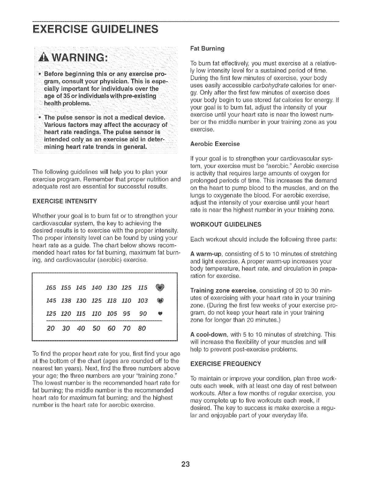
EXERCISE iNTENSiTY
Whether your goal is to burn fat or to strengthen your
cardiovascular system, the key to achieving the
desired results is to exercise with the proper
The proper intensity level can be found by using your
heart rate as a guide, The chart below shows recom-
mended heart rates for fat burning, maximum fat burn-
ing, and cardiovascular (aerobic) exercise,
165 155 I45 !40 130 125 115 _
!45 138 !30 125 I18 110 103 _
125 120 115 110 105 95 90
20 30 40 50 60 70 80
To find the proper heart rate for you, first find your age
at the bottom of the chart (ages are rounded off to the
nearest ten years), Next, find the three numbers above
your age; the three numbers are your "training zone,"
The lowest number is the recommended heart rate for
fat burning; the middle number is the recommended
heart rate for maximum fat burning; and the highest
number is the heart rate for aerobic exercise,
Fat Burning
To burn fat effectively, you must exercise at a relative-
ly low intensity level for a sustained period of time,
During the first few minutes of exercise, your body
uses easily accessible carbohydrate calories for ener-
gy, Only after the first few minutes of exercise does
your body begin to use stored fat calories for energy, if
your goal is to burn fat, adjust the intensity of your
exercise until your heart rate is near the lowest num-
ber or the middle number in your training zone as you
exercise,
Aerobic Exercise
if your goal is to strengthen your cardiovascular sys-
tem, your exercise must be "aerobic," Aerobic exercise
is activity that requires large amounts of oxygen for
prolonged periods of time, This increases the demand
on the heart to pump blood to the muscles, and on the
lungs to oxygenate the blood, For aerobic exercise,
adjust the intensity of your exercise until your heart
rate is near the highest number in your training zone,
WORKOUT GUiDELiNES
Each workout should include the following three parts:
A warm-up, consisting of 5 to 10 minutes of stretching
and light exercise, A proper warm-up increases your
body temperature, heart rate, and circulation in prepa-
ration for exercise,
Training zone exercise, consisting of 20 to 30 rain=
utes of exercising with your heart rate in your training
zone, (During the first few weeks of your exercise pro-
gram, do not keep your heart rate in your training
zone for longer than 20 minutes,)
A cooFdown, with 5 to 10 minutes of stretching, This
will increase the flexibility of your muscles and will
help to prevent post-exercise problems,
EXERCmSEFREQUENCY
To maintain or improve your condition, plan three work-
outs each week, with at bast one day of rest between
workouts, After a few months of regular exercise, you
may complete up to five workouts each week, if
desired, The key to success is make exercise a regu-
lar and enjoyable part of your everyday life,
23
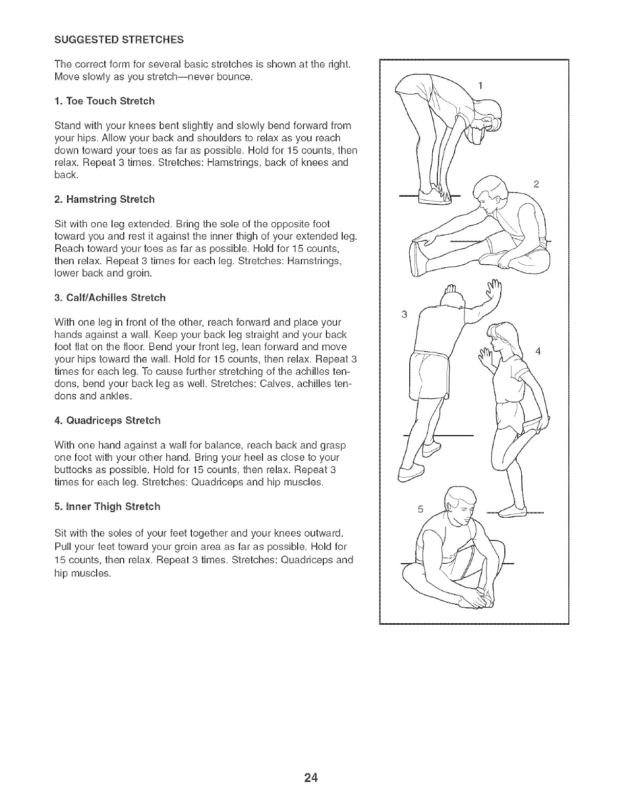
SUGGESTED STRETCHES
The correct form for several basic stretches is shown at the right,
Move slowly as you stretch--never bounce,
1. Toe Touch Stretch
Stand with your knees bent slightly and slowly bend forward from
your hips, Allow your back and shoulders to relax as you reach
down toward your toes as far as possible, Hold for 15 counts, then
relax, Repeat 3 times, Stretches: Hamstrings, back of knees and
back,
2. Hamstring Stretch
Sit with one leg extended, Bring the sob of the opposite foot
toward you and rest it against the inner thigh of your extended leg,
Reach toward your toes as far as possible, Hold for 15 counts,
then relax, Repeat 3 times for each leg, Stretches: Hamstrings,
lower back and groin,
3. CaJf/Achiltes Stretch
With one leg in front of the other, reach forward and place your
hands against a wall, Keep your back leg straight and your back
foot fiat on the floor, Bend your front leg, ban forward and move
your hips toward the wall, Hold for 15 counts, then relax, Repeat 3
times for each leg, To cause further stretching of the achilles ten-
dons, bend your back leg as well, Stretches: Calves, achilles ten-
dons and ankles,
4. Quadriceps Stretch
With one hand against a wall for balance, reach back and grasp
one foot with your other hand, Bring your heel as close to your
buttocks as possible, Hold for 15 counts, then relax, Repeat 3
times for each leg, Stretches: Quadriceps and hip muscles,
5. Inner Thigh Stretch
Sit with the sobs of your feet together and your knees outward,
Pull your feet toward your groin area as far as possible, Hold for
15 counts, then relax, Repeat 3 times, Stretches: Quadriceps and
hip muscles,
24
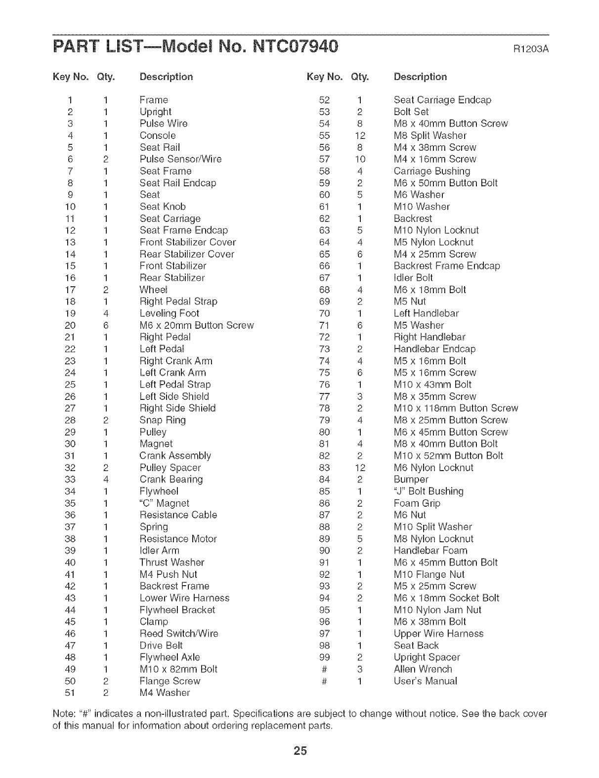
PART LiST--Model No. NT007940 Rt203A
Key No. Qty. Description Key No. Qty. Description
1 1 Frame 52 1 Seat Carriage Endcap
2 1 Upright 53 2 BoUtSet
3 1 PuUseWire 54 8 M8 x 40mm Button Screw
4 1 Consob 55 12 M8 Split Washer
5 1 Seat Rail 56 8 M4 x 38mm Screw
6 2 PuUseSensor/Wire 57 10 M4 x 16mm Screw
7 1 Seat Frame 58 4 Carriage Bushing
8 1 Seat Rail Endcap 59 2 M6 x 50mm Button BoUt
9 1 Seat 60 5 M6 Washer
10 1 Seat Knob 61 1 MIO Washer
11 1 Seat Carriage 62 1 Backrest
12 1 Seat Frame Endcap 63 5 MIO Nybn Locknut
13 1 Front Stabilizer Cover 64 4 M5 Nybn Locknut
14 1 Rear Stabilizer Cover 65 6 M4 x 25mm Screw
15 1 Front Stabilizer 66 1 Backrest Frame Endcap
16 1 Rear Stabilizer 67 1 Idler Bolt
17 2 Wheel 68 4 M6 x 18ram Bolt
18 1 Right Pedal Strap 69 2 M5 Nut
19 4 Leveling Foot 70 1 Left Handlebar
20 6 M6 x 20ram Button Screw 71 6 M5 Washer
21 1 Right Pedal 72 1 Right Handlebar
22 1 Left Pedal 73 2 Handlebar Endcap
23 1 Right Crank Arm 74 4 M5 x 16ram Bolt
24 1 Left Crank Arm 75 6 M5 x 16ram Screw
25 1 Left Pedal Strap 76 1 MIO x 43ram Bolt
26 1 Left Side Shield 77 3 M8 x 35ram Screw
27 1 78 2 MIO x 118ram Button Screw
28 2 Snap Ring 79 4 M8 x 25ram Button Screw
29 1 Pulley 80 1 M6 x 45mm Button Screw
30 1 Magnet 81 4 M8 x 40mm Button Bolt
31 1 Crank Assembly 82 2 MIO x 52mm Button Bolt
32 2 Pulley Spacer 83 12 M6 Nylon Locknut
33 4 Crank Bearing 84 2 Bumper
34 1 Flywheel 85 1 "J" Bolt Bushing
35 1 "C" Magnet 86 2 Foam Grip
36 1 Resistance Cable 87 2 M6 Nut
37 1 Spring 88 2 MIO Split Washer
38 1 Resistance Motor 89 5 M8 Nylon Locknut
39 1 Idler Arm 90 2 Handlebar Foam
40 1 Thrust Washer 91 1 M6 x 45mm Button Bolt
41 1 M4 Push Nut 92 1 MIO Flange Nut
42 1 Backrest Frame 93 2 M5 x 25mm Screw
43 1 Lower Wire Harness 94 2 M6 x 18mm Socket Bolt
44 1 Flywheel Bracket 95 1 MIO Nylon Jam Nut
45 1 Clamp 96 1 M6 x 38mm Bolt
46 1 Reed Switch/Wire 97 1 Upper Wire Harness
47 1 Drive Belt 98 1 Seat Back
48 1 Flywheel Axle 99 2 Upright Spacer
49 1 MIO x 82mm Bolt # 3 Allen Wrench
50 2 Flange Screw # 1 User's Manual
51 2 M4 Washer
Note: "#" indicates a non-illustrated part, Specifications are subject to change without notice, See the back cover
of this manual for information about ordering replacement parts,
25
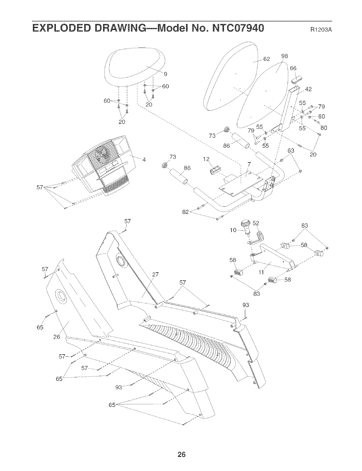
EXPLODED DRAWING--Model No. NT007940 n12O3A
98
/55 779
20
_f
57
/52
\
\
83
65
26
\\
27
57
58
83
93
26
81
f\
91
90
89
44
81
72
21
23 ,'_'At_::JJ
31
68
94 I'_
83
,54
56
,54
NTC07940 R1203A
27
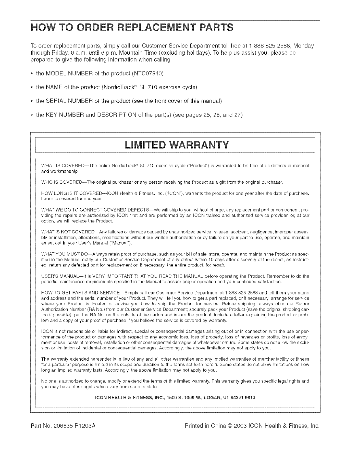
HOW TO ORDER REPLACEMENT PARTS
To order repUacement parts, simpUycall our Customer Service Department toll-free at 1o888o825o2588, Monday
through Friday, 6 a,m, until 6 p,m, Mountain Time (excluding holidays), To heUpus assist you, pUeasebe
prepared to give the following information when calling:
the MODEL NUMBER of the product (NTC07940)
the NAME of the product (NordicTrack ® SL 710 exercise cycle)
,, the SERUAL NUMBER of the product (see the front cover of this manuaU)
,, the KEY NUMBER and DESCRUPTUON of the part(s) (see pages 25, 26, and 27)
LiMiTED WARRANTY
WHAT IS COVERED--The entire NordicTrack '_SL 710 exercise cycle ("Product") is warranted to be free of all defects in material
and workmanship.
WHO IS COVERED--The original purchaser or any person receiving the Product as a gift from the original purchaser.
HOW LONG IS IT COVERED--ICON Health & Fitness, Inc. ("ICON"), warrants the product for one year after the date of purchase.
Labor is covered for one year.
WHAT WE DO TO CORRECT COVERED DEFECTS--We will ship to you, without charge, any replacement part or component, pro-
viding the repairs are authorized by ICON first and are performed by an iCON trained and authorized service provider, or, at our
option, we will replace the Product.
WHAT IS NOT COVERED--Any failures or damage caused by unauthorized service, misuse, accident, negligence, improper assem-
bly or installation, alterations, modifications without our written authorization or by failure on your part to use, operate, and maintain
as set out in your User's Manual ("Manual").
WHAT YOU MUST DO--Always retain proof of purchase, such as your bill of sale; store, operate, and maintain the Product as spec-
ified in the Manual; notify our Customer SePvice Department of any defect within 10 days after discovery of the defect; as instruct-
ed, return any defected part for replacement or, if necessary, the entire product, for repair.
USER'S MANUAL--It is VERY IMPORTANT THAT YOU READ THE MANUAL before operating the Product. Remember to do the
periodic maintenance requirements specified in the Manual to assure proper operation and your continued satisfaction.
HOW TO GET PARTS AND SERVICE--Simply call our Customer Service Department at t-888-825-2588 and tell them your name
and address and the serial number of your Product. They will tell you how to get a part replaced, or if necessary, arrange for service
where your Product is located or advise you how to ship the Product for service. Before shipping, always obtain a Return
Authorization Number (RA No.) from our Customer Service Department; securely pack your Product (save the original shipping car-
ton if possible); put the RA No. on the outside of the carton and insure the product. Include a letter explaining the product or prob-
lem and a copy of your proof of purchase if you believe the service is covered by warranty.
ICON is not responsible or liable for indirect, special or consequential damages arising out of or in connection with the use or per-
formance of the product or damages with respect to any economic loss, loss of property, loss of revenues or profits, loss of enioy-
ment or use, costs of removal, installation or other consequential damages of whatsoever nature. Some states do not allow the exclu-
sion or limitation of incidental or consequential damages. Accordingly, the above limitation may not apply to you.
The warranty extended hereunder is in lieu of any and all other warranties and any implied warranties of merchantability or fitness
for a particular purpose is limited in its scope and duration to the terms set forth herein. Some states do not allow limitations on how
long an implied warranty lasts. Accordingly, the above limitation may not apply to you.
No one is authorized to change, modify or extend the terms of this limited warranty. This warranty gives you specific legal rights and
you may have other rights which vary from state to state.
ICON HEALTH & FITNESS, INC., 1500 S. 1000 W., LOGAN, UT 84321-9813
Part No, 206635 R1203A Printed in China © 2003 ICON Health & Fitness, Inc,
