Nordyne Forced Air Gas And Oil Furnace M1B Users Manual 708672 0 M1 Series Ii.pmd
M1S to the manual 5a1af561-ceb4-4a34-a864-91928164f97b
2015-02-05
: Nordyne Nordyne-Forced-Air-Gas-And-Oil-Furnace-M1B-Users-Manual-404092 nordyne-forced-air-gas-and-oil-furnace-m1b-users-manual-404092 nordyne pdf
Open the PDF directly: View PDF ![]() .
.
Page Count: 40
For installation in:
1. Manufactured Homes
2. Recreational Vehicles, Park Models,
Manufactured Buildings
3. Modular Homes/Buildings
!
WARNING:
If the information in this manual is not
followed exactly, a fire or explosion
may result causing property damage,
personal injury or loss of life.
– Do not store or use gasoline or other
flammable vapors and liquids in the
vicinity of this or any other appli-
ance.
– WHAT TO DO IF YOU SMELL GAS
• Do not try to light any appliance.
• Do not touch any electrical switch;
do not use any phone in your build-
ing.
• Immediately call your gas supplier
from a neighbor’s phone. Follow the
gas supplier’s instructions.
• If you cannot reach your gas sup-
plier, call the fire department.
– Installation and service must be per-
formed by a qualified installer, ser-
vice agency or the gas supplier.
! WARNING:
Should overheating occur, or the gas
supply fail to shut off, shut off the
manual gas valve to the appliance
before shutting off the electrical sup-
ply.
! WARNING:
Improper installation, adjustment, al-
teration, service or maintenance can
cause injury or property damage. Re-
fer to this manual. For assistance or
additional information consult a quali-
fied installer, service agency or the
gas supplier.
Owners Manual/Installation Instructions
Series M1B, M1G, M1M and M1S
Downflow, Direct Vent (Sealed Combustion)
Forced Air Gas and Oil Furnaces
LEAVE THESE INSTRUCTIONS WITH THE HOMEOWNER.
2
TABLE OF CONTENTS
1. SPECIFICATIONS ................................................................................... 3
2. OWNERS INFORMATION ....................................................................... 3
3. MANUFACTURER WARRANTY, OWNER RESPONSIBILITY ................. 3
4. INSTALLATION STANDARDS ................................................................. 5
5. UNIT LOCATION ..................................................................................... 6
6. MINIMUM CLEARANCES ........................................................................ 6
7. RETURN AIR PROVISIONS .................................................................... 6
8. AIR DISTRIBUTION SYSTEMS .............................................................. 8
9. ROOF JACK SELECTION ....................................................................... 8
10. DUCT CONNECTOR SELECTION ........................................................... 9
11. INSTALLATION ..................................................................................... 11
12. INSTALLATION OF TRANSIT-MODE VENTING SYSTEM ................... 14
13. ELECTRICAL WIRING ........................................................................... 15
14. FUEL PIPING ........................................................................................ 16
15. FLUE GAS SAMPLING.......................................................................... 19
16. LIGHTING AND FURNACE SHUT DOWN .............................................. 20
17. SERVICE GUIDE ................................................................................... 25
18. MAINTENANCE ..................................................................................... 30
19. OPTIONAL ACCESSORIES .................................................................. 31
20. WIRING DIAGRAMS ......................................................................... 34-39
21. EQUIVALENT ORIFICE SIZES AT HIGH ALTITUDES .......................... 40
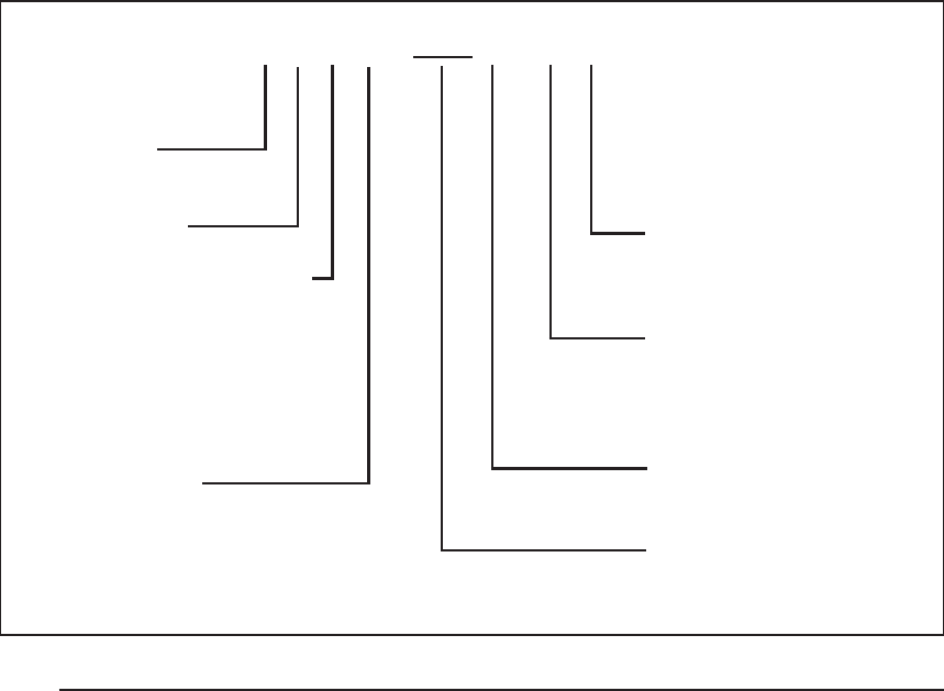
Table 1. Model Identification
Door Color
W - White
G - Gray
Cabinet Dimensions
A - 56" x 19-3/4" x 23-3/4”
B - w/Coil Cavity,
76" x 19-3/4" x 23-3/4"
Electrical Code
A - 1PH, 60 Hz, 120 VAC
Heating Capacity
Input, BTUH (000’)
Application
M-Manufactured Home
Furnace Series
Fuel, Type of Combustion
G-Gas, Direct Vent, Pilot Burner
Natural or Forced Draft
M-Gas, Direct Vent, HSI,
Forced Draft
B-Gas, Direct Vent, Gun Burner
S-Oil, Direct Vent, Gun Burner
Comfort Model
H - Heating
A - Heating, A/C Ready
B - A/C Ready, 3 Ton
C - A/C Ready, 4 Ton
D - A/C Ready, 5 Ton
M 1 M B - 056 A - B W

3
!
WARNING:
Do not use this appliance if any part
has been submerged under water.
Immediately call a qualified service
technician to inspect the appliance
and to replace any part of the control
system and any gas control that has
been submerged underwater.
NOTICE TO INSTALLER
Installer is advised to follow carefully all instruc-
tions and warnings in this manual to insure
maximum performance, safety, and operating
efficiency of these appliances. Improper instal-
lation may create hazardous conditions, and
will void the appliance warranty.
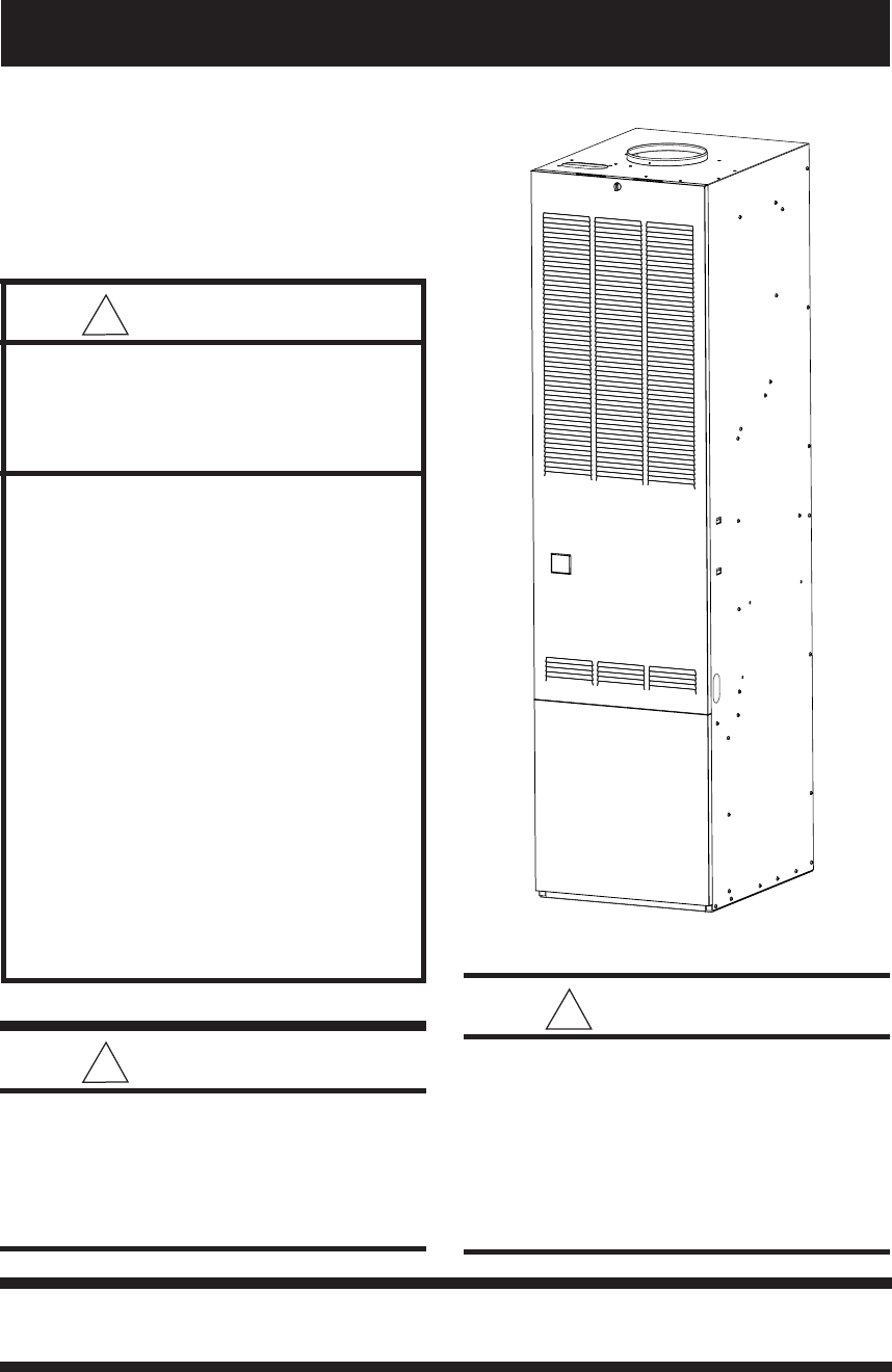
1.SPECIFICATIONS
General Description
M1 Series gas and oil furnaces are listed direct
vent (sealed combustion), downflow heating
appliances for manufactured (mobile) homes,
recreational vehicles, and for use in residential/
modular/commercial construction. The furnace
must be located so that venting can be properly
achieved.
Air conditioning may be added to structures with
M1 series furnaces using Platinum series air
conditioning or conventional units. This Instal-
lation Instruction manual includes special re-
quirements for incorporation of air conditioning
equipment to the M1 series of furnaces.
Multi-speed blower assemblies as shown in
Table 3 have been certified for field installation
in M1 Series furnaces. An air conditioner can be
easily field installed with M1GH Series furnaces
if used in conjunction with certified 2-wire relay
box, p/n 903092A or 4/5 wire relay box 902898A.
2.OWNER INFORMATION
ABOUT YOUR CENTRAL
FURNACE SYSTEM
NORDYNE has been involved in the design of
products for the manufactured home industry
since the first manufactured home or trailer was
built.
NORDYNE originated the sealed combustion
system, which separates the furnace combus-
tion system from the living area of the home,
now a standard for the manufactured home
industry.
NORDYNE engineers developed the first cen-
tral heating system and the first central air
conditioner for manufactured homes.
NORDYNE is dedicated to bringing to its cus-
tomers the finest heating and cooling comfort
possible. NORDYNE constantly seeks to fur-
ther refine its products to continuously provide
exceptional comfort.
Follow the instructions in this booklet carefully
and this appliance will provide many years of
superior performance.
If you wish to cool your home automatically with
a central air conditioning system investigate the
excellent NORDYNE cooling systems avail-
able from your heating and cooling contractor.
These systems are designed to work best with
your NORDYNE furnace and have been care-
fully engineered to deliver optimum performance
when mated with NORDYNE manufactured
home furnaces.
NORDYNE also offers water heaters, fire-
places and ventilating systems specifically de-
signed for manufactured housing applications.
Check with your manufactured home retailer,
your heating and cooling contractor or your
distributor for information. Write directly to the
factory (PO Box 46911, St. Louis, MO 63146)
if you are not able to locate a source for
NORDYNE manufactured housing products in
your area.
3. MANUFACTURER WARRANTY,
OWNER’S RESPONSIBILITIES
It is the sole responsibility of the homeowner to
make certain the gas furnace has been cor-
rectly set up and converted to the proper fuel
(L.P. gas or Natural gas) and adjusted to oper-
ate properly. All gas furnaces are manufac-
tured for Natural gas and must be field con-
verted when using L.P. gas.
A warranty certificate with full details is included
with these instructions. However, NORDYNE
will not be responsible for any costs found

4
necessary to correct problems due to improper
setup, improper installation, furnace adjust-
ments, improper operating procedure on the
part of the user, etc.
Some specific examples of service calls which
cannot be included in warranty payments are:
1. Converting the furnace to use another type
of gas.
2. Repairing duct work in the home found to be
faulty.
3. Correcting wiring problems in the electrical
circuit supplying the furnace.
4. Resetting circuit breakers, blown fuses or
other switches.
5. Correcting problems due to improper gas
supply pressure to the furnace.
6. Providing instructional training on how to
light and operate the furnace.
7. Furnace problems caused by installation of
an air conditioner, heat pump or other air
comfort devices.
8. Adding a Roof Jack extension because of
unusual wind and/or snow conditions.
9. Revising installation of the furnace flue as-
sembly (Roof Jack).
10. Adjusting or calibrating of thermostat.
11. Any construction debris which falls into flue
system.
Electrical Supply - 120 volts, 60HZ, 1 Ph.
Fuse or Breaker - 15 amps
Temperature Rise - 45° to 75°F
High Altitude - See Table 11. For Canadian
High Altitude (2,000’ to 4,500’), reduce the
gas manifold pressure to 3.0” W.C. for
natural gas and to 8” W.C. for LP gas.
Thermostat Circuit - 24 volts, 60HZ, 30 vac
Normal Anticipator Setting - 0.4
Manifold Pressure - Natural Gas: 3.5” w.c.
LP Gas: 10” w.c.
*Blower capacity only - needs relay box for AC
Table 2. M1 Furnace Specifications
Furnace Input Output Orifice No E.S.P. Pilot Ignitor Comb. Motor A/C Ready
Model No MBtu/h MBtu/h Nat. LP In WC Burner Direct Blower Hp Tons
M1GH 056 56 45 29 45 0.3 x 1/8 2*
M1GB 056 56 45 29 45 0.3 x 1/4 3
M1GC 056 56 45 29 45 0.3 x 1/2 4
M1GD 056 56 45 29 45 0.3 x 3/4 5
M1GH 070 70 57 24 42 0.3 x 1/5 2½*
M1GB 070 70 57 24 42 0.3 x 1/4 3
M1GC 070 70 57 24 42 0.3 x 1/2 4
M1GD 070 70 57 24 42 0.3 x 3/4 5
M1GH 077 77 62 21 40 0.3 x x 1/4 3*
M1GB 077 77 62 21 40 0.3 x x 1/4 3
M1GC 077 77 62 21 40 0.3 x x 1/2 4
M1GD 077 77 62 21 40 0.3 x x 3/4 5
M1GH 090 90 72 17 36 0.3 x x 1/4 3*
M1GB 090 90 72 17 36 0.3 x x 1/4 3
M1GC 090 90 72 17 36 0.3 x x 1/2 4
M1GD 090 90 72 17 36 0.3 x x 3/4 5
M1MA 056 56 46 29 45 0.3 x x 1/8 2
M1MB 056 56 46 29 45 0.3 x x 1/4 3
M1MC 056 56 46 29 45 0.3 x x 1/2 4
M1MD 056 56 46 29 45 0.3 x x 3/4 5
M1MA 070 70 57 24 42 0.3 x x 1/5 2½
M1MB 070 70 57 24 42 0.3 x x 1/4 3
M1MC 070 70 57 24 42 0.3 x x 1/2 4
M1MD 070 70 57 24 42 0.3 x x 3/4 5
M1MB 077 77 62 21 40 0.3 x x 1/4 3
M1MC 077 77 62 21 40 0.3 x x 1/2 4
M1MD 077 77 62 21 40 0.3 x x 3/4 5
M1MB 090 90 72 17 36 0.3 x x 1/4 3
M1MC 090 90 72 17 36 0.3 x x 1/2 4
M1MD 090 90 72 17 36 0.3 x x 3/4 5
M1BA 066 66 53 26 43 0.3 x x 1/5 2½
M1BB 066 66 53 26 43 0.3 x x 1/4 3
M1BC 066 66 53 26 43 0.3 x x 1/2 4
M1BB 086 86 68 18 37 0.3 x x 1/4 3
M1BC 086 86 68 18 37 0.3 x x 1/2 4
M1SA 066 66 54 .50 Gph 0.3 x 1/5 2½
M1SB 066 66 54 .50 Gph 0.3 x 1/4 3
M1SC 066 66 54 .50 Gph 0.3 x 1/2 4
M1SB 086 86 71 .65 Gph 0.3 x 1/4 3
M1SC 086 86 71 .65 Gph 0.3 x 1/2 4
Burner Model
AF-10 Nozzle
Spray Angle
80° A
5
Carefully review these responsibilities with your
manufactured housing dealer, service com-
pany or gas supplier so there will be no misun-
derstanding at a later time.
! CAUTION:
• Never attempt to alter or modify this
furnace or any of its components.
• Never attempt to repair damaged or
inoperable components. Such action
could cause unsafe operation, explo-
sion, fire and/or asphyxiation.
• If a malfunction has occurred, or if
you feel that the furnace is not oper-
ating as it should, contact a qualified
service agency or gas utility for as-
sistance.
4.INSTALLATION STANDARDS
Installer shall be familiar with and comply with all
codes and regulations applicable to the instal-
lation of these heating appliances and related
equipment. In lieu of local codes, the installation
shall be in accordance with the current provi-
sions of one or more of the following standards.
Table 3. Field Installation Blower Assemblies
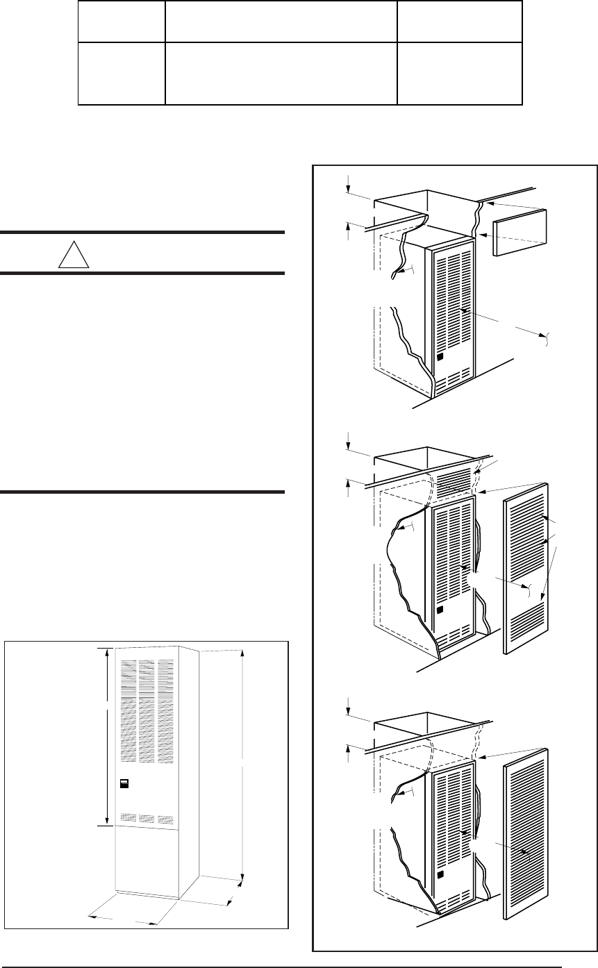
Figure 1. Overall Dimensions
“A”- 56"
23 3/4"
“B”- 76"
19 3/4"
“A” Model-
w/o Coil Cabinet
“B” Model-
w/Coil Cabinet
Removable access
panel should be
installed above
furnace door frame
to access roof jack
Nearest
Wall or
Partition
18"
(457 mm)
6" (152 mm)
Top Clearance
0" Side
Clearance
to Furnace
Cabinet
6" (152 mm)
Top Clearance
0" Side
Clearance
to Furnace
Cabinet
Provide min. 235
sq. in. (1516 cm )
open free area in
front or side wall
2
or
In closet
door
located
at top,
center
or bottom
CLOSET DOOR
6" (152 mm)
Top Clearance
Provide min. 250
sq. in. (1613 cm )
open free area in
front or side wall
2
a fully
louvered
door may
be used
CLOSET DOOR
6"
(152 mm)
1"
(25 mm)
0" Side
Clearance
to Furnace
Cabinet
or
in closet
door
Figure 4. Special 1” Clearance
Figure 3. Closet Installation
Figure 2. Alcove Installation
A/C Capacity
Blower Wheel Motor-Hp Ton
903773 10 x 8 1/4 2, 2½ & 3
903413 11 x 8 1/2 2, 2½, 3 & 4
903414 11 x 8 3/4 2, 2½, 3, 4 & 5
Part No. Blower / Motor Assembly
6
ALL MODELS CLOSET ALCOVE
Front 6" 18"
Back 0" 0"
Sides 0" 0"
Roof Jack 0" 0"
Top 6" 6"
Top and Sides of Duct 0" 0"
Bottom of Duct
B Cabinet 0" 0"
A Cabinet (w/ coil box) 0" 0"
A Cabinet (w/o coil box) 1/4" 1/4"
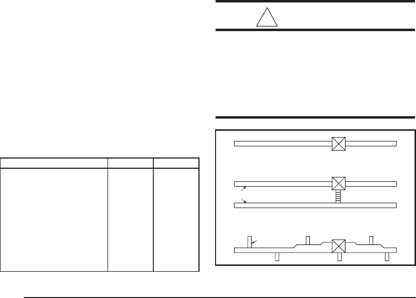
Table 4. Minimum Clearances Figure 5. Non-Platinum
Supply Duct System
A Single trunk duct
BDual trunk duct
w/crossover connector
C
Transition duct
w/branches
a. Federal Manufactured Home Constructions
& Safety Standard (H.U.D. Title 24, Part
3280.707[a][2])
b. American National Standard (ANSI-119.2/
NFPA-501C) for all recreational vehicle in-
stallations.
c. American National Standard (ANSI-Z223.1/
NFPA-54) and/or CAN/CGA B149 for all gas-
fired furnace models.
d. American National Standard (ANSI-Z95.1/
NFPA-31) and/or CSA B139 for all oil-fired
furnace models.
e. American National Standard (ANSI-C1/
NFPA-70) and/or CSA 22.1 Canadian Elec-
tric Code Part 1 for all electrical field wiring.
f. Units have been investigated under stan-
dards UL 307A & B, UL727-1999, ANSI
21.47a - CAN/2.3a - 1995, and CSA B140.10.
5.UNIT LOCATION
The furnace shall be appropriately located to
the supply and return air distribution system.
(See “AIR DISTRIBUTION”, Page 8) Sides and
back of the furnace may be enclosed by wall
framing. (See “Minimum Clearances,” Table 4,
and Figures 2 through 5.)
The furnace installation is only intended for free
air return through the furnace door louvers. DO
NOT connect a ducted return air system di-
rectly to the furnace. Improper installation may
create a hazard and damage equipment, as well
as void all warranties.
Furnace may be installed on combustible floor-
ing when using NORDYNE Duct Connectors
(see Section 10).
When installed in a residential garage, the fur-
nace must be positioned so the burners and the
source of the ignition are located no less than
18 inches above the floor and protected from
physical damage by vehicles.
6.MINIMUM CLEARANCES
This heating appliance must be installed with
clearances not less than the minimums shown
in Table 4. This heating appliance must be
installed with ample clearance for easy access
to the air filter, blower assembly, burner assem-
bly, controls, and vent connections.
a. Alcove installations (see Figure 2): minimum
18" clearance at front of furnace shall be
provided for future servicing. A removable
access panel should be installed between
top of the furnace door frame and the ceiling.
b. Closet installations must use a louvered door
having a minimum free area of 235 sq. in.
when located 6" from furnace (See Figure 3)
or 390 sq. in. for 5 ton ready M1 furnaces. For
special clearance between 1" and 6", re-
quirements are a louvered door with a mini-
mum of 250 sq. in. free area, with the open-
ings in the closet door in line with the louvered
openings in the furnace door . A fully louvered
closet door may be used (See Figure 4 and
section 7.i. to evaluate compliance with this
requirement).
7.RETURN AIR PROVISIONS
U.S.A. home manufacturers shall comply with
all of the following conditions to have acceptable
return air systems for closet installed forced air
heating appliances:
! CAUTION:
HAZARD OF ASPHYXIATION: Nega-
tive pressure inside the closet, with
closet door closed and the furnace
blower operating on high speed, shall
be no more negative than minus 0.05
inch water column.
7
ROOF JACK
SLANT DECK
FLASHING
PITCHED
ROOF
CEILING
CEILING CAVITY
ROOF OPENING
CEILING OPENING
"X" (SEE TABLE 6)
S O T 27 45 -5
S= SLAT FLASHING
F= FLAT FLASHING
O= TYPE; STANDARD
H= HIGH WIND
A= ARCTIC ROOF JACK
T= TRANSIT
MODE
TYPE
MIN. ADJ.
LENGTH
MAX. ADJ.LENGTH
5 = 5" FLUE DIA.
MODEL APPROX. ADJ.
NUMBER LENGTHS*
BELOW FLASHING
FO1323 -5 13" - 23"
FO2343 -5 23" - 43"
SO1835 -5 18" - 35"
SO2447 -5 24" - 47"
SO3263 -5 32" -63"
SO4895 -5 48" - 95"
SOT2442 -5 24" - 42"
SOT2745 -5 27" - 45"
SOT4581 -5 45" - 81"
FOT2846 -5 28" - 46"
Table 5. Roof Jack Assemblies
a. Regardless of the location, the return air
opening into the closet shall not be less than
specified in the appliance’s listing.
b. Means shall be provided to prevent inadvert-
ent closure by a flat object placed over the
return air opening when it is located in the floor
of the closet (versus the vertical front or side
wall).
c. The cross-sectional area of the return duct
system leading into the closet, when located
in the floor or ceiling shall not be less than 235
square inches (or 390 square inches for 5 ton
ready M1 Furnaces).
d. The total free area of openings in the floor or
ceiling registers serving the return air duct
system must be at least 235 sq. in. At least
one register should be located where it is not
likely to be covered by carpeting, boxes and
other objects.
e. Materials located in the return duct system
must have a flame spread classification of
200 or less. This includes a closet door if the
furnace is in a closet.
f. Noncombustible pans having 1" upturned
flanges are located beneath openings in a
floor duct system.
g. Wiring materials located in the return duct
system shall conform to Articles 300-22 of
the National Electrical Code (ANSI C1/NFPA-
70).
SSAW T27 47 - 2
AW= ALL WEATHER
FLASHING
PITCH/12" RISE
0=FLAT
2=2.5/12
4=4/12
MIN. ADJ.
LENGTH
F=
S=
FLAT FLASHING
SLANT FLASHING TYPE:
BLANK=NON-TRANSIT
T= TRANSIT MODE
MAX. ADJ.
LENGTH
FLUE STEEL TYPE
A= ALUMINIZED
S=STAINLESS
All Weather Roof Jack Assemblies
Approx. Length
Model Number Below Flashing
(F,S)AW(T)1523-(0,2,4)(A,S) 15" - 23"
(F,S)AW(T)2135-(0,2,4)(A,S) 21" - 35"
(F,S)AW(T)2747-(0,2,4)(A,S) 27" - 47"
(F,S)AW(T)3563-(0,2,4)(A,S) 35" - 63"
(F,S)AW(T)5195-(0,2,4)(A,S) 51" - 95"
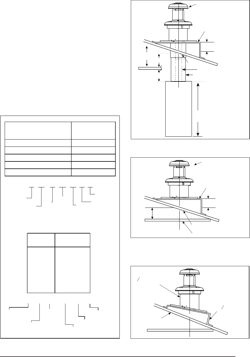
Figure 6. Roof Jack Assemblies
ROOF JACK
SLANT DECK
FLASHING
PITCHED
ROOF
CEILING
CEILING
CAVITY
ROOF
OPENING
"X" (SEE TABLE 1)
Flue Pipe
Combustion
Air Pipe
56" or 76"
Furnace
"A"
"B"
Figure 7. Example of Flat Jack
with Flashing
Figure 8. Example of 2½/12 Slant Jack
with Flashing
5/12 ROOF SLOPE
2
SLANT DECK
/12
12
R
OOF JACK WITH
2
F
LASHING
/12 SLANT
12
8
b. F=Flat Flashing; flexes from 0/12 to 1/12 roof
slope.
c. S=Slant Flashing. 2.5/12 Slope flexes from 1/
12 to 4/12 roof slope, 4/12 flexes from 3/12
to 5/12.
d. Stainless steel roof jacks are available.
e. If the roof jack crown is covered or blocked
with snow, the furnace will not operate prop-
erly. If the home is located in regions where
snow accumulation exceeds 7” (HUD
snowload zones) use an external roof jack
extension p/n 901937.
f. M1 furnaces may be used with roof jacks as
tall as 170” (except M1M 056 & M1B 066
models, which are limited to 120”). An internal
roof jack extension (p/n 901935 - 10”, p/n
903107 - 18”) can be used to increase roof
jack height. All connections inside the home
must be made below the ceiling.
These extensions are available as optional
accessories and may be purchased through
your NORDYNE distributor.
h. Gas piping is not run in or through the return
duct system.
i. Test the negative pressure in the closet with
the air-circulating fan operating at high speed
and the closet closed. The negative
pressure is to be no more negative than
minus 0.05 inch water column.
j. Air conditioning systems may require more
duct register and open louver area to ob-
tain necessary airflow. Use NORDYNE’s
certiduct program to determine proper duct
size for A/C.
8.AIR DISTRIBUTION SYSTEMS
For proper air distribution, the supply duct
system must be designed so that the static
pressure measured external to the furnace
does not exceed the listed static pressure
rating shown on the furnace rating plate.
Location, size, and number of registers should
be selected on the basis of best air distribution
and floor plan of the home.
!
CAUTION:
HAZARD OF ASPHYXIATION: Do not
cover or restrict return air opening.
9.ROOF JACK SELECTION
Note: Install only Roof Jack Assemblies listed
in Table 5 on this heating appliance.
a. Determine depth of ceiling cavity from center
of roof opening to center of ceiling opening.
(See Dimension “A” in Figure 6.)
b. Determine ceiling height and subtract height
of furnace. (See Dimension “B” in Figure 6.)
c. Add dimensions A + B (and X from Table 6 and
Figure 7 if slant deck flashing is used). The
total length of (A + B + X) must be within the
minimum and maximum range of one of the
Roof Jacks listed in Table 5.
APPLICATION NOTES:
a. FAW, FAWT, SAW and SAWT Series Roof
Jacks with a 5" diameter inner vent pipe may
be used with all models of M1 Series gas and
oil furnaces.
Table 6. Slant Deck Flashings
Table 7. Floor Cavity Sizes
Optional Deck Flashings for Flat and 2.5/12 Pitch
Roof Jacks.
(4/12 Pitch Roof Jacks not applicable.)
USE SLANT DECK
IF ROOF PITCH IS: FLASHING NO. "X" FACTOR IS:
"F Series Roof Jack
2" in 12" 903893 (2.5/12) 2-1/8"
2-1/2" in 12" 903893 (2.5/12) 2-1/2"
3" in 12" 903894 (3/12) 2-7/8"
3-1/2" in 12" 903894 (3/12) 3-1/4"
4" in 12" 903895 (4/12) 3-5/8"
"S" Series Roof Jack (2.5/12 Pitch only)
4-1/2" in 12" 903895 (2.5/12) 2-1/8"
5" in 12" 903895 (2.5/12) 2-1/2"
5-1/2" in 12" 903894 (3/12) 2-7/8"
6" in 12" 903894 (3/12) 3-1/4"
6-1/2" in 12" 903895 (4/12) 3-5/8"
English Metric (mm) Finger Tab Screw Down
7/8" 22 901987 904008
2" 51 901988 904009
4-1/4" 108 901989 904010
6-1/4" 159 901990 904011
8-1/4" 210 901991 904012
10-1/4" 260 901992 904013
12-1/4" 311 901993 904014
Use Duct Connector
Model Part Number:
If "X"
(
Floor Cavit
y)
is:
9
10. DUCT CONNECTOR SELECTION b. Select appropriate model from Table 7
which matches X-dimension of the floor
cavity. To maximize air delivery, re-
move reducer “C” (see Figure 11) to
obtain the largest open area that will fit
the duct/floor construction. Screw down
duct connector opening to duct without
reducer is 13” x 13”. With reducer it is
13” x 10-1/8”.
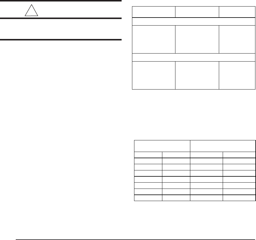
Figure 10.
Figure 9.
13 1/4"
10 1/4"
19”
19"
Top View
of
Finger Tab
Duct
Connector
x
SUPPLY AIR DUCT
FLOOR CAVITY
(depth equal to "X" in Figure 11 and Table 7)
Figure 11.
XSEE
TABLE 7
REDUCER
*FELT-SEAL
SPACERS
C
*OPENING TO DUCT
WITH PLATE (C) REMOVED
OPENING BECOMES
13-1/4” x 13-1/4”
*INDICATES FINGER TAB DUCT CONNECTOR ONLY
PLATINUM SERIES
a. For Platinum ready construction use
the 14” round duct connector, p/n:
903896.
NON-PLATINUM SERIES
a. Determine depth of floor cavity from
surface of floor to top of supply air duct
(See Figure 9).
10
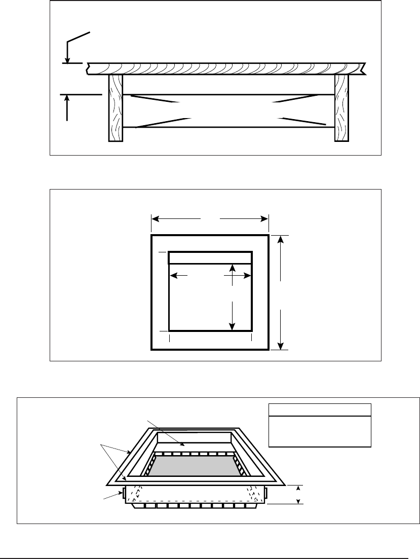
Figure 12. Closet or Alcove
CEILING AND ROOF
OPENINGS
C
L
C
L
13-1/2"
10"
23 -1/4"
FLOOR
OPENING
C
L
C
L
A
LT. FUEL
L
INE HOLES
SIDE WALL
REAR WALL
FUEL LINE
HOLE
FLOOR CUT-OUT
FOR DUCT CONN.
CEILING
CUT-OUT FOR
FLUE AND
ROOF JACK
(See Fig 12)
C
L
C
L
C
L
C
L
24"
23-1/4"
21-3/4"
14-1/2"
2-1/4"
2-3/4"
20"
14-1/2"
13-1/2"
FURNACE OUTLINE
FLOOR CUT-OUT
FOR OPTIONAL
COOLING COIL
FOR NON-PLATINUM
SERIES UNITS
10"
12-7/8"
14-3/4"
15-1/2"
1-1/4" D.
ALT FUEL-LINE
ENTRY FURNACE
OUTER DOOR
REAR WALL OF CLOSET OR ALCOVE
FUEL-LINE
1-3/4"
2"
3/4"
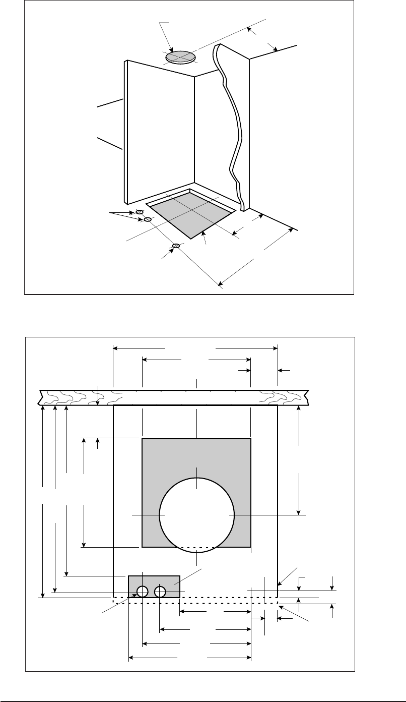
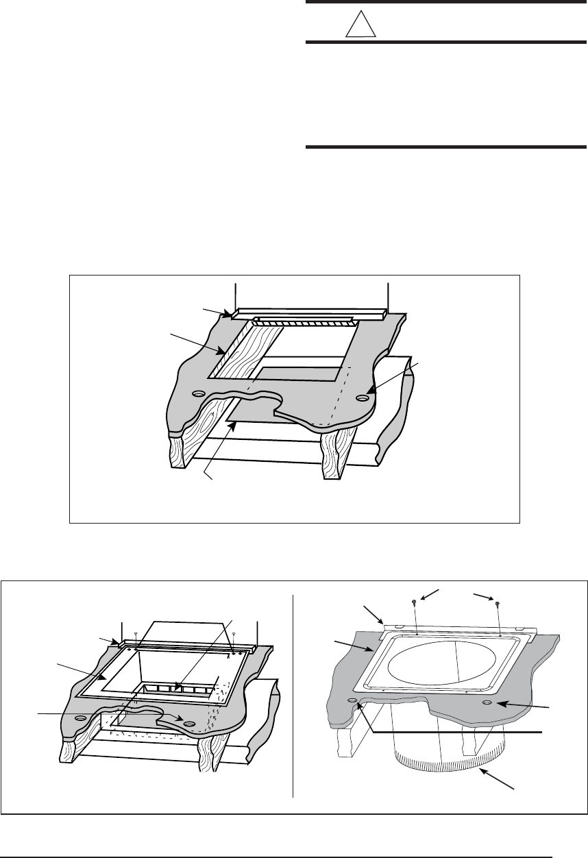
Figure 13. Cut-Out Locations
11
11. INSTALLATION
Required floor, ceiling, and roof cut-out open-
ings must be carefully located to avoid misalign-
ment of the furnace and Roof Jack (see Figures
12 & 13). Installation procedures are suggested
for typical furnace installations and need not be
followed in the exact listed sequence.
CUT OUT FLOOR OPENING & FUEL LINE
HOLE
a. Determine center of closet or alcove (Figure
13).
b. Locate center of the floor opening, measured
10" from the rear wall, and mark cut-out
measuring approximately 14-1/2" by 14-1/2"
(± 1”) for model duct connector used (refer
to Figures 10 & 11).
c. Locate center of fuel line hole, measured 23-
1/4" from the rear wall and 6-5/8" to the left of
center of the floor cut-out (See Figure 12) or
5-1/4" to the left of center of the floor cut-out,
or for entry through right-side of furnace
measured 9" to the right of center of the floor
cut-out.
d. Cut out floor opening and one fuel line hole.
! IMPORTANT:
Refer to the installation instructions
provided with optional air conditioning
packages when installing furnaces with
optional cooling coil cabinet or with
optional C***-series indoor coils.
CUT OUT CEILING AND ROOF OPENINGS
a. Locate center of Roof Jack opening, mea-
sured 13 1/2" from the rear wall of closet or
alcove along the center line of furnace and
floor opening. (See Figure 13)
Figure 15. Duct Connector
Figure 14. Mounting Plate
REAR WALL
MOUNTING
PLATE
FLOOR
OPENING
FUEL
LINE
HOLES
SUPPLY AIR DUCT
CUT DUCT OPENING
1/16TH. LARGER THAN
DUCT CONNECTOR
REAR WALL
SUPPLY AIR DUCT
FUEL
LINE
HOLES
MOUNTING
PLATE
FLOOR
OPENING
UNDER DUCT OPENING
Non-Platinum Series Platinum Series
DUCT
CONNECTOR
MOUNTING
PLATE
SCREWS
FUEL
LINE
HOLES
14” SUPPLY
CONNECTION
12
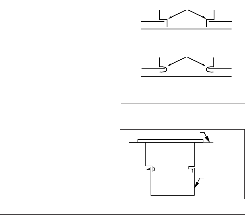
Figure 16. Installation of Duct Connector
b. Cut ceiling and roof holes as follows:
Ceiling Hole = 8-3/4" (222 mm) diameter
Roof Hole = 9-3/8" (238 mm) diameter
c. DO NOT ALLOW DEBRIS TO FALL INTO
THE FURNACE. THIS COULD CAUSE
UNSAFE OPERATION AND VOIDS THE
FURNACE WARRANTY. Use the top cap
that comes with the furnace packaging (or
alternate protector) to prevent debris from
falling into the furnace before the final roof
jack connection is made.
CUT DUCT OPENING (FINGER TABBED
ONLY)
a. Place duct connector through the floor open-
ing with bottom tabs resting on top of the
supply air duct.
b. Center duct connector and push back against
rear edge of floor opening.
c. Mark cut-out location (tab area) and remove
duct connector.
d. Cut out duct opening 1/4" larger than area
marked.
INSTALL FURNACE MOUNTING PLATE
a. Place mounting plate (supplied within duct
connector) at rear of the floor opening (See
Figure 15).
INSTALLING PLATINUM SERIES 14” ROUND
DUCT CONNECTOR
a. Place duct connector through the floor open-
ing. (See Figure 15).
b. Secure duct connector to floor.
INSTALLING SCREW DOWN DUCT CON-
NECTOR
a. Apply a bead of caulking, mastic, or other
approved sealant around bottom side of 1/2”
flange and restrictor plate, when applicable.
b. Locate the duct connector over duct and
carefully lower screw down duct connector
into place.
c. Once duct connector is located on duct,
temporarily hold in place while fastening duct
connector to the floor using flat head screws
or nails. Be sure flanges of duct connector
stay in contact with the duct.
d. Screw plenum to duct making sure a seal is
made between the duct and the duct connec-
tor. Additional screws may be added if re-
quired.
e. Cut away duct along edge of flange allowing
the center to drop into the duct. Remove
section of duct with caution, as edges will be
sharp.
INSTALLING FINGER TABBED DUCT CON-
NECTORS
a. Place duct connector through the floor open-
ing with bottom tabs extending through the
duct opening. (See Figure 15)
b. Secure duct connector to floor.
c. Bend bottom tabs under and up tightly against
the supply air duct (See Figure 16).
NOTE: The duct connector is designed for use
on ducts 12" in width. When using the connector
on 12" wide ducts, there may be insufficient
clearance to bend the tabs on two sides of the
duct connector. In such cases the tabs may be
attached to the sides of the duct by using sheet
metal screws or other suitable fasteners. (See
Figure 17).
If sealant, mastic, or tape is used to provide a
better seal, it should be approved by applicable
national or local codes.
ALTERNATE ATTACHMENT METHODS
This procedure may also be used to install a
furnace duct connector to narrow metal
ductwork where insufficient clearance prevents
Duct
Duct Connector
Narrow Duct
Figure 17.
TABS
TABS
DUCT
DUCT
1. INSERT DUCT CONNECTOR INTO
DUCT CUT-OUT.
2. BEND BOTTOM TABS OVER
AND ONTO THE UNDERNEATH
DUCT SERVICE.
13
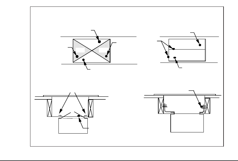
Staple Folded Duct
Flap (typ) to side of Duct
Connector
Duct
STEP 4.
STEP 1.
"A" "A"
"B"
"B" Cut- Out
Area"A"
Cut- Out
Area "A"
Fold Back Flap "B"
Fold Back Flap "B"
Top of Duct
"A" "A"
STEP 2.
"B"
"B"
Fold Back Flap"B"
Cut
Lines Duct
Fold Back Flap"B"
STEP 3.
Bend Duct Connector Tabs Up
and Over- (along length of duct)
Duct
Flap "B"
Duct
Figure 18.
bending of the duct connector tabs at the
side(s) of the duct. (See Figure 18).
1. Score and cut the top of the metal duct as
indicated in Step 1 or Step 2. With Step 1
choice, also cut out the metal from the shaded
area “A”.
2. Fold the duct flap “B” up, (See Step 3).
3. At the front-to-back of duct run (Area “A”),
bend the duct tabs and secure them directly
to the duct.
4. At Area “B”, bend the duct tabs up and back
over, around the duct connector, (See
Step 3).
5. Fold/form the duct flap against the side of the
duct connector and attach as shown, (See
Step 4). Use three (3) staples (minimum) on
each duct flap OR, if a 2X block/joist is not
provided, use two (2) sheet metal screws
(minimum) on each duct flap. An alternate
attachment method is acceptable, as long as
the duct connector is securely attached.
6. Tape the duct flap edges with an approved
tape for a leak-free joint.
INSTALL FURNACE
a. Remove furnace outer door(s) and bottom
fuel line knockout.
b. Place furnace onto duct connector and cen-
ter with floor opening.
c. Slide onto mounting plate. (Bottom rear slots
on furnace should engage with mounting
plate tabs.)
d. Secure front with one (1) fastener at each
corner (See Figure 19 or 20).
NOTE: Additional fasteners may be used at
rear, sides or through door frame, as desired,
to secure furnace to closet or alcove framing.
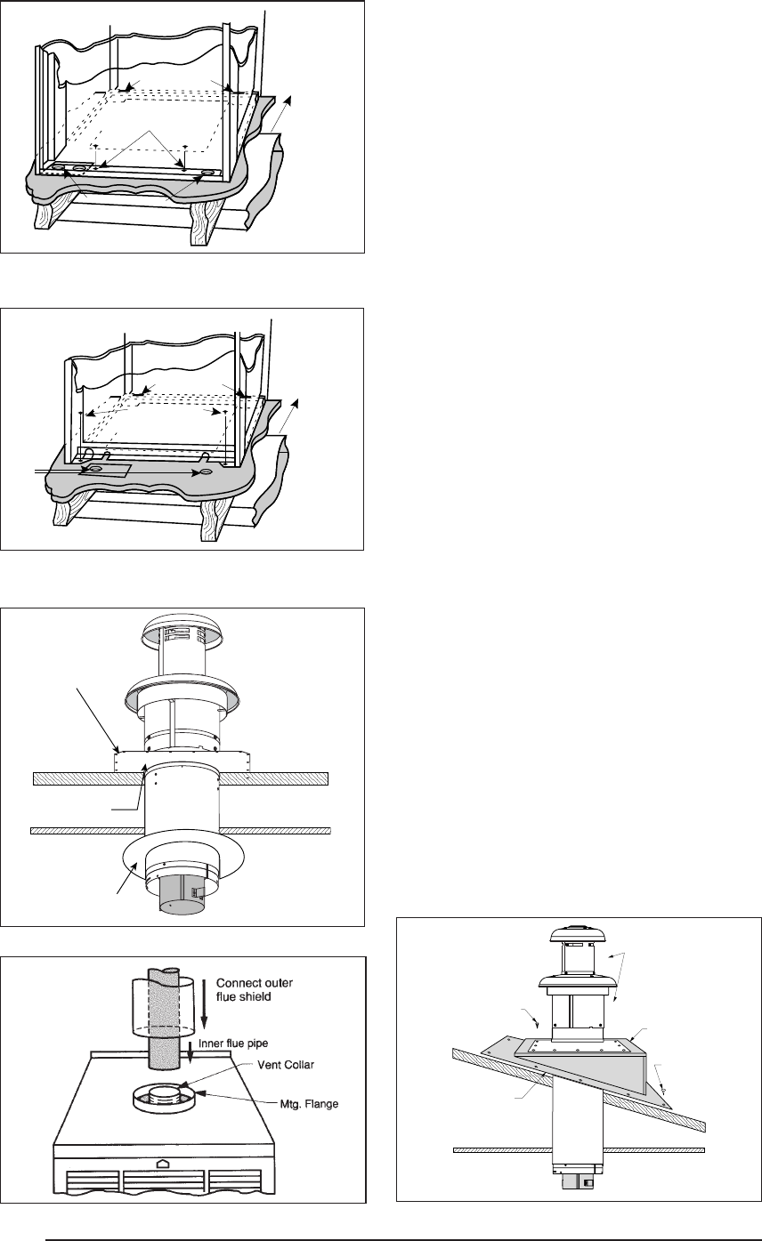
INSTALL ROOF JACK
Apply caulking compound on underside of roof
flashing to form a continuous strip at least 3/8"
wide (see Figure 21) around the underside of
the perimeter of the flashing. Connect Roof
Jack Assembly to the furnace. Insert telescop-
ing Roof Jack Assembly through the opening
cut on the roof. Connect flue pipe to flue collar
of furnace. Connect combustion air pipe to
furnace collar with sheet metal screw (See
Figure 22). It is recommended that the connec-
tion of the combustion air pipe to the furnace be
made before the flashing is secured to the roof
to maintain alignment of roof jack and furnace
connections.
NOTE: For replacement furnaces, be sure the
inner flue pipe connects over the furnace vent
collar. DO NOT use a smaller diameter inner
flue pipe which could slide inside the fur-
nace vent collar and restrict the flow of
furnace flue products.
Attach Roof Flashing: If necessary, shift roof
flashing slightly in the roof opening so that
assembly is in good alignment with furnace.
Press down firmly over caulking on roof flashing
to make the seal with roof water tight. Secure
flashing with appropriate fasteners. As an
14
MTG. PLATE TABS SLIDE FURNACE
ALL THE WAY BACK
ONTO MTG. PLATE
SUPPLY AIR DUCT
Knockout Over Holes
SECURE FURNACE
WITH 2 FASTENERS AT FRONT
CORNER HOLES
SUPPLY AIR DUCT
FUEL
LINE
HOLES
MTG. PLATE TABS SLIDE FURNACE
ALL THE WAY BACK
ONTO MTG. PLATE
SECURE FURNACE
WITH 2 FASTENERS
AT FRONT CORNER HOLES
Figure 19. “A”, “B”, & Platinum
Cabinet Furnaces
Figure 20. “A” Cabinet Furnace on 911969
Coil Cabinet (Non-Platinum Series)
added protection against leaks, coat the flash-
ing plate and fasteners with approved roofing
compound.
If flashing mounted on 12 degree angle is used
it may be necessary to adjust the angle to match
the roof pitch; (1/12 - 4/12 maximum).
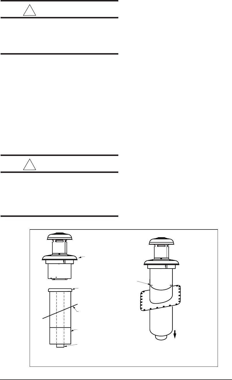
12. INSTALLATION OF TRANSIT-
MODE VENTING SYSTEM
MANUFACTURED HOME FACTORY
a. Furnace to be installed per furnace installa-
tion manual.
b. Roof Jack to be selected from Table 5 of
these instructions.
c. Roof Jack (less upper Roof Jack crown),
with weather cap to be installed as described
under Install Roof Jack.
d. Upper Roof Jack crown to be stored in a
prominent location inside manufactured home
until on-site installation.
e. The four warning tags supplied must be
installed as follows:
• To weather cap
• To fuel line connection point (Gas) or
furnace burner (Oil)
• To furnace flame observation door (Gas
or Oil)
• To furnace wall thermostat
MANUFACTURED HOME SITE
a. Transit-mode weather cap to be removed
and upper Roof Jack crown installed (See
Figure 24).
b. Place upper Roof Jack (crown) on to the flue
pipe assembly. Be sure inside flue pipe
attaches over inner flue pipe. Be sure outer
Roof Jack pipe fits over outer pipe. Secure
in place using three (3), #10, 1/2" sheet metal
screws removed in step #a. Do not use the
same holes which secured the rain cap in
place.
Secure Roof Jack with
appropriate fasteners
after connecting to
furnace
Ceiling
Caulk under roof
flashing to prevent
water leakage
Roof
Optional #901943
Ceiling Trim Ring
or #902521
2-piece Ceiling Ring
Figure 21. Flat Roof
Ceiling
Caulk under roof
flashing to prevent
water leakage
Secure flashing
with appropriate
fasteners
Secure lower roof
jack section with
no. 10 S.M. screws
Roof
Upper Roof
Jack Section
Optional
Slant-Deck
Flashing
Figure 23. Pitched RoofFigure 22.
15
c. Venting system warning tags to be removed
and discarded.
!
WARNING:
Failure to properly secure the flue pipe
to the furnace may result in fire, explo-
sion or asphyxiation when operating
the furnace.
13. ELECTRICAL WIRING
Refer to the wiring diagram in these instructions
or affixed to the inside of the control box cover
for the wiring of your particular unit.
ELECTRICAL BRANCH SUPPLY CIRCUITS.
Route all electrical wiring to the left side of the
furnace. For installation of “A” Cabinet fur-
naces, allow sufficient slack in the wiring if an
optional cooling coil cabinet is added at a later
time.
Use of copper conductors is recom-
mended.
! WARNING:
Any attempt to operate furnace before
replacing transit-mode weather cap
with upper roof jack section may re-
sult in hazard of fire, explosion or as-
phyxiation.
Power supply circuit to the furnace must be
installed and grounded in accordance with the
National Electrical code (ANSI-C1/NFPA-70),
or Canadian Electric Code Part 1 (CSA 22-1)
and all local codes having jurisdiction.
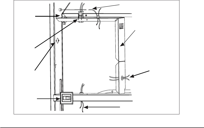
CONNECT POWER SUPPLY WIRES
a. Remove the furnace control panel cover.
b. Insert 115 volt wires through the strain relief
on the left side of the furnace control box (see
Figure 25).
c. Connect the “hot” wire to the BLACK pigtail
lead, and the “neutral” wire to the WHITE
pigtail lead. Secure all connections with
suitable wire nuts.
d. Connect the “ground” wire to the grounding
screw.
e. Reinstall the control panel cover and secure
with the original mounting screws.
CONNECT THERMOSTAT WIRES
a. Insert 24 volt wires through the plastic grom-
met just above the control panel.
b. Connect the thermostat wires to the furnace
low voltage pigtails (see Figure 25).
c. Connect low-voltage circuit to the wall ther-
mostat.
d. A hole may be made in the furnace cabinet to
ease thermostat wiring. Make sure that the
wiring is protected from the sharp edge of the
added hole.
NOTE: The thermostat should be installed 4 to
5 feet above the floor on an inside wall which is
relatively free from direct sources of heat or
SCREWS
COMPLETED
ASSEMBLY
TO FURNACE
UPPER ROOF
JACK (CROWN)
INNER FLUE
PIPE
FLUE ASSEMBLY
OUTER PIPE
FLASHING
WEATHER CAP
Figure 24.
16
If the heat anticipator is set too low, the furnace
may cycle frequently and not provide comfort
to the homeowner.
14. FUEL PIPING
Sizing and installation of fuel lines must be in
accordance with federal, state and local regu-
lations. All piping shall be black iron pipe, or
equivalently sized steel tubing. Internally tinned
copper tubing may be used for gas supply
systems.
Fuel line installations other than typical installa-
tions shown in Figures 26 and 27 must comply
with the fuel piping provisions stated in the
Federal Manufactured Home Standard (H.U.D.
TITLE 24, PART 280) and the National Fuel Gas
Code (ANSI-Z223.1/NFPA-54).
a. Optional fuel inlet lines are available for all gas
furnace models to permit the addition of a 1/
2" F.P.T. shut-off valve above the floor.
NOTE: Shut-off valve must be designed and
listed for use with liquid petroleum (L.P. gas).
The gas supply to your home will either be
Natural Gas or L.P. (bottle gas). Your furnace
is factory equipped to operate on Natural Gas.
If your gas supply is L.P. (bottle gas), you must
contact a qualified serviceman or gas supplier
to convert the furnace. The necessary instruc-
tions for the gas conversion are found on the
lighting instruction label attached to the furnace
in Section 16, Service Guide.
cold drafts. The nominal anticipator setting is
0.4. (Refer to the thermostat literature for addi-
tional information.)
Five-conductor thermostat wire is recom-
mended for 24 volt low-voltage circuit (2-wire is
required for furnace only; 5-wire for heating and
optional cooling systems).
For Platinum-ready Construction:
a. Use a heat/cool thermostat.
b. Run thermostat wire from the Thermostat to
the Furnace (see Figure 39).
c. Using thermostat wire with at least two wires
(four wire is recommended), run thermostat
wire from the Furnace to the intended loca-
tion of the Platinum-series unit. Leave at least
six feet of extra thermostat wire at the in-
tended location for future hook-up. Coil re-
maining six feet of wire and attach to the
home’s undercarriage.
Once the furnace is installed check the thermo-
stat anticipator against the nominal setting of
0.4:
1. Connect the milliamp meter in series with one
of the gas valve’s low voltage terminals.
2. Energize the gas valve.
3. Read the value of the milliamps.
4. Adjust the heat anticipator of the thermostat
to the value read on the milliamp meter.
If the heat anticipator is set too high, the furnace
may delay in coming on.
Figure 25. Control Panel (All Models)
To Combustion
Blower or
Flame Roll-Out
Switch
Thermostat Wires
Blower
Plug
On-Off
Switch
On-Auto
Switch
(Heating
Models Only)
To Gas Valve
or Burner
Power
Entry
Furnace
Control Box
17
Table 8. Thermostat Wire Gauge
To Gas
Supply
Floor
Control
Panel
On-Off-Fan
Switch
Alt. Fuel
Line Entry
Floor Cavity
Figure 26. Typical Gas Piping
For natural gas operation, the furnace is de-
signed for 7" W.C. inlet pressure. Pressure is
reduced to 3-1/2" W.C. by the pressure regu-
lator in the gas valve. The maximum inlet
pressure for the valve is 13” W.C.
For L.P. gas, pressure to the gas valve must
be more than 11" W.C. but not more than 13"
W.C. Pressure is reduced to 10" W.C. by the
pressure regulator in the gas valve.
! CAUTION:
The furnace must be converted by a
qualified technician. Improper conver-
sion can cause unsafe operation, ex-
plosion, fire and/or asphyxiation.
Oil Tank and Piping Installation
The following procedures are recommended
as good practice. However, requirements of
local codes and ordinances, H.U.D. Manufac-
tured Home and Safety Standards or National
Fire Protection Association must be satisfied,
where they apply, for an approved installation.
Use a tank capacity suitable for the application
with a weatherproof, capped fill opening and a
shielded vent to let in air as fuel is used. The tank
must be clean inside before filling. All water, rust,
sediment and other foreign matter must be
flushed out.
A fuel or tank gauge is recommended for easy
checking of the fuel level. Check the gauge
reading with a dipstick.
Locate the storage tank conveniently near the
home. For above ground fuel tank installations,
the tank may rest three to four inches off the
T’STAT
Wire Gauge
2-Wire 5-Wire
(Heating) (Heating/Cooling)
24 55 25
22 90 45
20 140 70
18 225 110
Recommended T’STAT Wire
Len
g
th
(
Unit to T’STAT
)
18
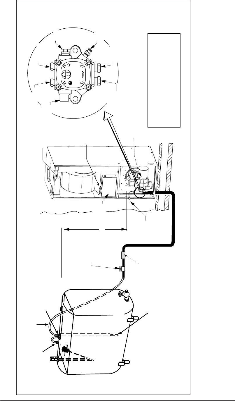
Figure 27. Typical Oil Piping for Above Ground (Single-Line) Supply
If fuel pump fails to lift oil, check for air
port plug and repeat priming procedure.
leaks and tighten all fuel fittings. Re-
prime fuel pump by injecting fuel oil into
optional (top) return port. Replace return
R
Top of Tank
8 ft.
Shut-off
Valve
Optional
Fuel
Filter
Alternate
Fuel Line
Entry
Optional
Return
Pressure
Gauge Port
Nozzle
Port
Inlet
Port
Air-Bleed
Valve
Return Port &
Internal By-Pass
Optional
Inlet
Control
Panel
Oil
Furnace
On-Off-Fan
Switch
Floor Cavity
Oil-Gun
Burner
Floor
Flue Gas
Sampling
Hole
Drain
End of Oil Supply Line
3" to 5" Above
Bottom Drain
Guide pipe
Gauge
Vent with
Cap 2" Duplex
Bushing
2" Fill
3/8" Oil Supply Line
Note: Additional venting
may be required if tank
is filled rapidly.

19
ground. Fuel tanks may also be buried if prop-
erly coated to resist corrosion. For below ground
fuel tank installations, the vertical dimension
from the bottom of the fuel tank to the fuel pump
must not exceed ten feet. Keep the tank filled,
especially in the summer to reduce the accu-
mulation of condensation.
Fuel Line Hook-Up: One Line System
The one line system is highly recommended
where vertical lift, from bottom of tank to pump,
is not more than eight feet. A single line hookup
has the advantage of costing less and giving
quieter operation.
Fuel Line Hook-Up: Two Line System
Use a two line system only if the vertical lift
exceeds 8 feet.
1. Install the oil feed line as outlined in steps 1-
6 below.
2. Install the oil pump bypass plug in the bottom
return port.
3. Run the return line up through the furnace
base to the return port of the pump. Run the
other end of the line to the tank, using 3/8”
O.D. copper tubing or 1/4” pipe with the ends
capped, and routing the line so it stays clean.
4. Insert the return line through the second
opening in the duplex bushing. If the bottom
of the tank is lower than the pump intake, the
tube should be inserted three or four inches
from the tank bottom. If the bottom of the tank
is higher than the pump intake, the return line
should extend not more than 8” inside the
tank.
If a two pipe system is used or if oil is taken from
the bottom of the tank, a filter is recommended.
Hook-Up Procedure (See Figure 27)
1. Use a 3/8” O.D. copper tubing for the fuel line.
Cap the end with tape to keep out dirt while
the line is being routed.
2. Install duplex bushing for two 3/8” lines in the
top fitting of the tank.
3. Insert one end of the tubing through the
duplex bushing until it is three to five inches
from the bottom drain. Tighten the bushing.
4. Run the line where it will not be subject to
damage. Also, make bends gradually and
avoid kinks which might restrict oil flow.
5. Open the furnace door. Connect the oil line
to the intake port on the pump. Tighten other
port plugs on the pump.
6. Be sure oil line is airtight! Air leaks can cause
the pump to lose prime and will create other
problems such as nozzle failure, odors, rum-
bling noise, and false safety shutdown.
7. Insert the short length of the copper tube level
with the bottom of the duplex bushing. Form
the tube into an inverted “U” to serve as a
vent.
How to Eliminate Air Leaks
To eliminate problems caused by air in the oil
line, all connections in the oil supply line and all
plugs, nuts, and fittings on the pump must be
airtight. This includes the nut that covers the
pressure adjustment. It is important that the
hook-up be done carefully and with a good
flaring tool.
To assure continuous operation, use a wire to
jump terminals T-T (or F-F) on the primary
control while burner is running. If furnace is
equipped with the Honeywell R7184 primary
control, priming oil pump procedure is as fol-
lows:
1. While the ignition is on, press, for 1/2 second
or less, and release the reset button. The
lockout time will be extended to 4 minutes.
2. If prime is not established within the 4 min-
utes, the control will lock out. Press the reset
button to reset the control.
3. Repeat steps “1” and “2”, if needed, until the
pump is fully primed.
When oil flow is clear and free of air bubbles,
close air-bleed valve and tighten. (Time to bleed
air out will vary depending on length of oil line,
number of bends, etc.)
Fuel Oil Type
Do not use fuel oil heavier than Grade No. 2.
Grade No. 1 may be used where the oil supply
is subject to low temperatures.
DO NOT USE GASOLINE, CRANKCASE OIL,
OR ANY OIL CONTAINING GASOLINE.
! WARNING:
Failure to keep supply of oil clean by
various procedures described above
may cause failure of certain compo-
nents such as the fuel pump gears,
check valve, shaft seal, or burner
nozzle which may result in a burner
fire.

20
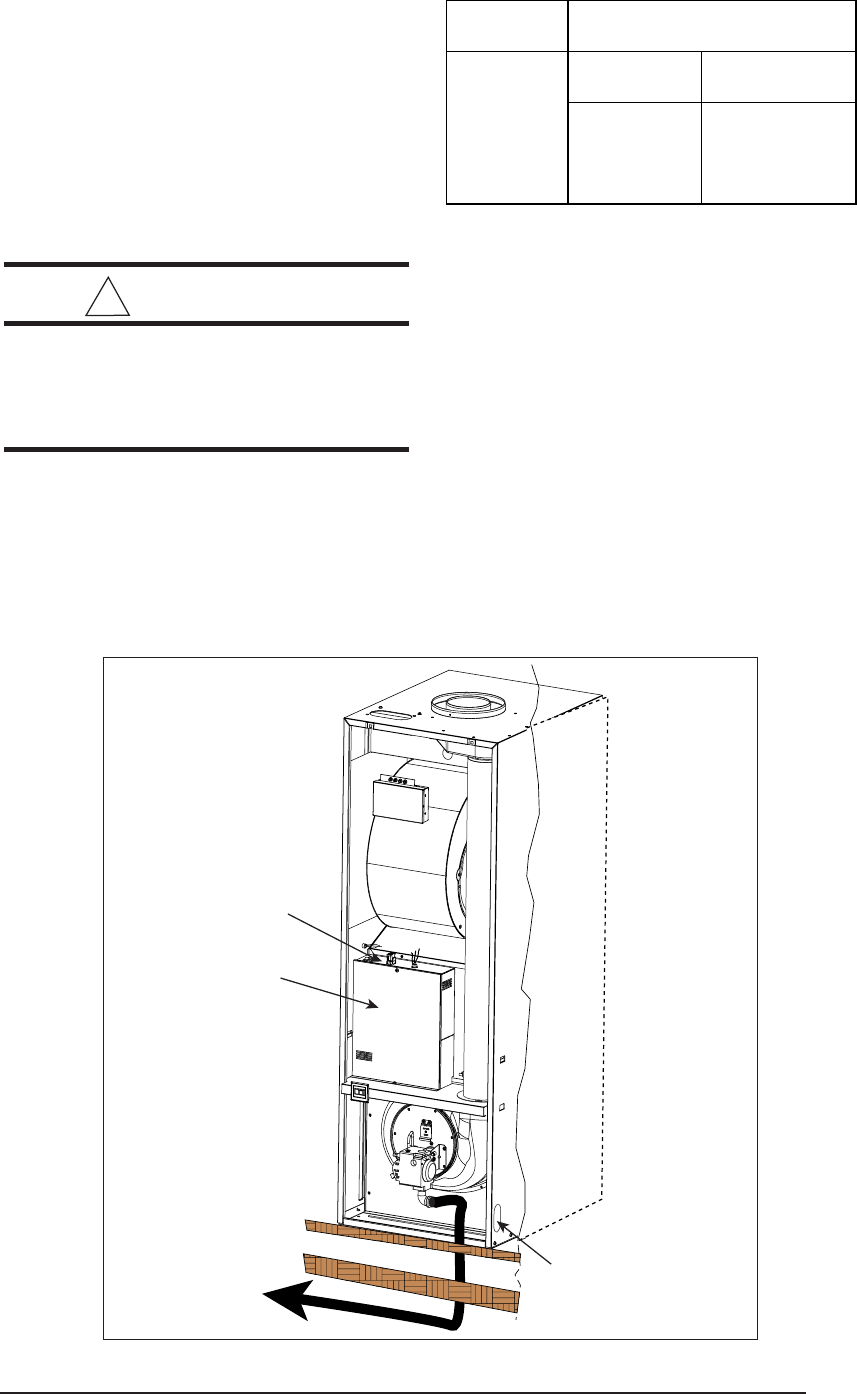
15. FLUE GAS SAMPLING
It may be necessary to take flue gas sampling
from oil and gas gun furnaces (M1S and M1B
Series Models) in order to check the perfor-
mance after furnace installation. A flue gas
sample may be taken from the heat exchanger,
which is located behind the hole of the top-front
of blower compartment.
1. STOP! Read the SAFETY INFORMATION.
2. Turn off all electric power to the appliance.
3. Remove the black plastic cap located above
the blower and save.
4. Through the top of the blower compartment
hole, drill a hole for your sampling tube into the
heat exchanger.
5. Insert sampling tube through the drilled hole.
6. After a complete check and adjustment of
furnace performance, fill the drilled hole with
a screw that is larger than the hole.
7. Put silicon sealant (rated at least 500° F)
around the screw.
8. Plug the outside hole with the plastic cap you
removed in step 3.
! WARNING:
If you do not follow these instructions
exactly, a fire or explosion may result
causing personal injury, loss of life, or
property damage.
16. LIGHTING AND SHUTDOWN
GENERAL-ALL MODELS
Read the safety information on the front page of
these installation instructions before lighting
furnace. DO NOT ATTEMPT TO LIGHT
FURNACE IF YOU SMELL GAS.
SAFETY INFORMATION
FOR YOUR SAFETY READ BEFORE LIGHT-
ING.
a. The first lighting of the furnace after any
home setup must be performed by a
qualified service technician.
b. If this appliance has a pilot that must be lit by
hand, follow these instructions exactly.
c. BEFORE LIGHTING smell all around the
furnace for gas. Be sure to smell next to the
floor because some gas is heavier than air
and will settle on the floor.
d. WHAT TO DO IF YOU SMELL GAS: Do not
try to light any appliance. Do not touch any
electric switch and do not use any phone in
your building. Immediately call your gas
supplier from a neighbor’s phone. Follow the
gas supplier’s instructions. If you cannot
reach your gas supplier, call the fire depart-
ment.
e. Use only your hand to push in the gas control
lever. Never use tools. If the lever will not
push in by hand, don’t try to repair it. Call a
qualified service technician. Force or at-
tempted repair may result in a fire or explo-
sion.
f. Do not use this furnace if any part has been
under water. Immediately call a qualified
service technician to inspect the furnace and
to replace any part of the gas valve or control
system which has been under water.
LIGHTING INSTRUCTIONS FOR STAND-
ING PILOT MODELS.
a. Stop! Read the safety information.
b. Set the thermostat to the lowest setting.
c. Turn off all electric power to the appliance.
d. Push in the gas control lever slightly and
move left to “OFF.” DO NOT FORCE.
e. Wait ten (10) minutes to clear out any gas.
If you then smell gas, STOP! Follow step “d”
in the SAFETY INFORMATION. If you don’t
smell gas, go to the next step.
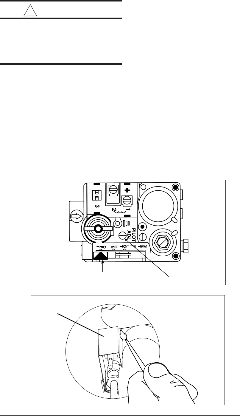
f. Find pilot - follow metal tube (pilot tube) from
gas control valve. Open hinged fire obser-
vation door. The pilot is found at the end of
the pilot tube just left of the pilot shield.
g. Slightly depress the gas control lever and
move it right to the “ON” position and release;
then move it to the “PILOT” position.
h. Move the control lever to “SET” and hold.
Immediately light the pilot with a match.
Continue to hold the control lever for about
one (1) minute after the pilot is lit. Release the
lever and it will spring back to the “PILOT”
position. Pilot should remain lit. If it goes out,
repeat steps “d” through “h” above. If the
lever does not spring back when released,
stop and immediately call your service tech-
nician or gas supplier. If the pilot will not stay
lit after several tries, move the gas control
lever to “OFF” and call your service techni-
cian or gas supplier.
i. Move the gas control lever left to “ON”.
j. Turn on all electric power to the furnace. Set
the thermostat to “Heat” and/or the desired
temperature setting. Set the On-Off-Fan
switch to “ON”.
k. Replace the furnace door.
21
Gas Control Lever
Pilot Adjustment
Figure 28. Standing Pilot Valve
Figure 29. Lighting Furnace
Pilot
Bracket
! WARNING:
Close hinged fire door. If fire door is
open or spring is broken it may allow
products of combustion into the living
space by the furnace blower resulting
in possible asphyxiation.
In the event of any flashback or explosion,
immediately shut off the furnace and call your
service technician.
TO TURN OFF GAS TO APPLIANCE:
a. Set the thermostat to the lowest setting.
b. Turn off all electric power to the appliance at
breaker or fuse box, before servicing.
c. Remove the furnace door.
d. Push in the gas control lever slightly and
move to the left to “OFF.” DO NOT FORCE.
e. Replace the furnace door.
SEQUENCE OF OPERATION FOR STAND-
ING PILOT
a On a call for heat, the thermostat contacts
close, supplying 24 VAC to the gas valve.
b. When the gas valve is energized it steps
open at a reduced flow and opens fully after
approximately 14 seconds.
c. When the call for heat is satisfied the thermo-
stat contacts open, the gas valve shuts off
gas flow.
SEQUENCE OF OPERATION FOR STAND-
ING PILOT W/INDUCED DRAFT BLOWERS
MODELS
a. On a call for heat, the thermostat contacts
close, supplying 24 VAC to the relay.
b. The relay contacts close and energize the
induced draft motor.
c. When the inducer starts, the air pressure
switch closes at -0.20”WC differential pres-
sure and energizes the gas valve.
d. When the gas valve is energized it steps
open at a reduced flow and opens fully after
approximately 14 seconds.
22
e. When the call for heat is satisfied the thermo-
stat contacts open, the gas valve shuts off
gas flow, and the induced draft blower stops.
GENERAL-DIRECT IGNITION MODELS
Read safety information on front page of these
installation instructions before operating fur-
nace. DO NOT ATTEMPT TO OPERATE
FURNACE IF YOU SMELL GAS.
Operating instructions for
M1M — MODELS WITH DIRECT IGNITION:
a. STOP! Read the SAFETY INFORMATION.
b. Set the thermostat to the lowest setting.
c. Turn off all electric power to the appliance.
d. This appliance is equipped with an ignition
device which automatically lights the burner.
Do not try to light the burner by hand.
e. Honeywell - push in the gas control knob and
turn clockwise to “OFF.” Robertshaw - push
the gas control lever to “OFF.” NOTE: The
lever cannot be placed in the “OFF” position
unless it is pushed in slightly. DO NOT
FORCE (See Figures 30 & 31).
f. Wait ten (10) minutes to clear out any gas. If
you smell gas, STOP! and follow step “d” in
the SAFETY INFORMATION section. If you
do not smell gas, go to the next step.
g. Set the On-Off switch to the “ON” position.
h. Honeywell - turn knob on gas control counter
clockwise to “ON.” Robertshaw - push the
gas control lever to “ON.”
i. Turn on all electric power to the appliance.
j. Replace the furnace door.
k. Set the thermostat to “HEAT” and the desired
temperature setting. The furnace should light
after approximately 75 seconds. If the appli-
ance will not operate, follow the instructions
“To Turn Off Gas To Appliance” and call your
service technician or gas supplier.
In the event of any flashback or explosion,
immediately shut off the furnace and call your
service technician.
TO TURN OFF GAS APPLIANCE:
a. Set the thermostat to the lowest setting.
b. Turn off all electric power to the appliance
before servicing unit.
c. Set the ON-OFF switch to “OFF.”
d. Honeywell - push in the gas control knob and
turn clockwise to “OFF.” Robertshaw - push
the gas control lever to “OFF.”
e. Replace the furnace door.
SEQUENCE OF OPERATION FOR M1M
MODELS WITH DIRECT IGNITION
Direct ignition model furnaces do not have a
pilot. Ignition is accomplished automatically by
a silicon carbide hot surface ignitor. A control
module takes care of all timing functions. After
lighting, the control module uses the ignitor as
a flame sensor, shutting off gas should the flame
go out. There are no external relays or timing
devices.
Do not try to light this furnace manually.
The control module is not field serviceable.
a. On a call for heat, the thermostat contacts
close, supplying 24 VAC between terminals
“C” and “W” of the control module, which
starts combustion motor.
b. When the inducer starts, the air pressure
switch closes at -0.20”WC differential pres-
sure and energizes the control.
c. After a 45 second purge period, the ignitor is
energized for a 30 second warm-up period,
after which the gas valve opens.
d. The trial period for ignition is approximately 6
seconds, after which the gas valve either
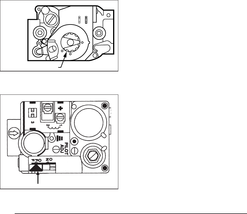
Gas Control
Figure 31. Direct Ignition
Gas Valve - Robertshaw
Figure 30. Direct Ignition
Gas Valve - Honeywell
GAS CONTROL KNOB

23
remains open if flame is sensed, or closes if
flame is not sensed.
e. If flame is not sensed, the entire sequence is
repeated four more times before “lockout”
occurs. To reset, wait 30 seconds and then
interrupt the 24 VAC power by turning the
room thermostat below room temperature,
then returning it to the original set point.
f. If flame is not established on the fifth trial for
ignition (initial try + 4 re-tries), the control de-
energizes the gas valve, flashes “4” on the
Status LED, and lockouts out heat operation
for 1 hour.
g. If a flame is present, the control energizes the
main blower on heat speed 30 seconds after
the gas valve opens.
h. When call for heat is satisfied the thermostat
contacts open, the gas valve shuts off gas
flow and the combustion blower remains on
for a 30 second post-purge period.
i. The main blower is de-energized after a 120
second blower off delay.
! WARNING:
FOR YOUR SAFETY; WHAT TO DO IF
YOU SMELL GAS:
• Do not try to light any appliance.
• Do not touch any electrical switch; do
not use any phone in your building.
• Immediately call your gas supplier
from a neighbor’s phone. Follow the
gas supplier’s instructions.
• If you cannot reach your gas sup-
plier, call the fire department. Should
overheating occur or the gas supply
fail to shut off, disconnect the power
at the main circuit breaker and then
see “To Turn Off Gas To Appliance.”
OPERATING INSTRUCTIONS FOR
OIL AND GAS GUN FURNACE:
Oil Gun Model
M1 oil gun furnaces may be converted to gas
gun in the field by using the proper conversion
kit listed in the RPL.
If your furnace model number begins with M1S*,
the furnace is equipped with an ignition device
which automatically lights the burner.
Do not try to light this furnace manually
.
a. Open all valves in the oil line.
b. Be sure the fire door is closed.
c. Set the On-Off switch to “ON”.
d. Set the thermostat to the desired setting.
SEQUENCE OF OPERATION FOR
OIL GUN MODELS
Oil Furnace - Honeywell R7184 Control
1. When a call for heat is initiated, there is a 2-
6 second delay while the control performs a
safe start check.
2. The ignition and motor are turned on and a
flame should be established within the 15-
second lockout time. NOTE: Burner will
prepurge for 15 seconds if equipped with
R7184B Control.
3. If flame is not sensed within the 15-second
lockout time, the control shuts down on
safety lockout and must be manually reset.
If control locks over three times in a row, the
control enters restricted lockout. To reset,
hold down the reset button for 30 seconds
until the LED flashes twice.
4. Once flame is established, the ignition re-
mains on 10 seconds to ensure flame stabil-
ity. It then turns off.
5. The circulating air blower will energize after
the temperature fan switch closes.
6. The furnace runs until the call for heat is
satisfied.
7. The circulating air blower will de-energize
when the temperature fan switch opens.
! WARNING:
If furnace still does not light, turn the
furnace off (described above) and call
your technician. In the event of any
flashback or explosion, immediately
shut off furnace and call your service
technician.
Gas Gun Models
M1 gas gun furnaces may be converted to oil
gun in the field by using the proper conversion
kit listed in the RPL.
If your furnace model number begins with M1B*,
the furnace does not have a pilot. Ignition is

24
accomplished automatically by a silicon car-
bide hot surface ignitor. A control module takes
care of all lighting and timing functions. There
are no external relays or timing devices.
Do not try to light this furnace manually.
The control module is not field serviceable.
1. Before operation, smell all around the fur-
nace for gas. Be sure to smell next to the
floor because some gas is heavier than air
and will settle on the floor. If you smell gas,
STOP! and follow the safety instructions
below. If you don’t smell gas, go to the next
step.
2. Set the thermostat to the lowest setting.
3. Turn off all electric power to the appliance.
4. This appliance is equipped with an ignition
device which automatically lights the burner.
Do not try to light the burner by hand.
5. Honeywell - push in the gas control knob
and turn clockwise to “OFF.” Robertshaw
- push the gas control lever to “OFF.”
NOTE: The lever cannot be placed in the
“OFF” position unless it is pushed in slightly.
DO NOT FORCE (See Figures 30 & 31).
6. Wait ten minutes to clear out any gas. If you
then smell gas, STOP! and follow the safety
information on the preceding page. If you
don’t smell gas, go to the next step.
7. Set the On-Off switch to the “ON” position.
8. Honeywell - turn knob on gas control counter
clockwise to “ON.” Robertshaw - push the
gas control lever to “ON.”
9. Turn on the electric power to the appliance.
10. Set the thermostat to “Heat” and/or the
desired temperature setting. The furnace
should light in approximately 45 seconds.
If the appliance will not operate, follow the
instructions “To Turn Off Gas To Appli-
ance” and call your service technician or
gas supplier.
In the event of any flashback or explosion,
immediately shut off the furnace and call
your service technician.
SEQUENCE OF OPERATION FOR
GAS GUN MODELS
a. On a call for heat, the furnace control begins
an ignition sequence which lasts approxi-
mately 45 seconds.
b. After this sequence, the control module tests
to see if flame is sensed. If it has, the furnace
continues to heat until the thermostat is
satisfied.
c. If the burner has not lit, the ignition sequence
is repeated a maximum of two more times. If
flame is not sensed after three attempts, the
control enters “Lockout” and no further at-
tempts to light the burner will occur. If
“Lockout” occurs, contact a qualified service
technician for assistance.
! DANGER:
Before placing the furnace in service
it must be checked to make sure it is
equipped for the type of gas being
used. The burner flame must also be
observed and adjusted if necessary.
Failure to observe this caution may
result in unsafe operation, explosion
and/or fire, or asphyxiation. See the
following sections “Gas Supply” and
“Combustion Air.”
d. When call for heat is satisfied, the thermostat
contacts open and the gas valve shuts off
gas flow.
TO TURN OFF GAS/OIL APPLIANCE:
a. Set the thermostat to the lowest setting.
b. Turn off all electric power to the appliance
before servicing unit.
c. Set the On-Off Switch to “OFF.”
d. Honeywell - turn gas control knob clockwise
to “OFF” Robertshaw - Push the gas control
lever to “OFF.”
e. For oil, shut off all valves.
f. Replace the furnace door.
THE FURNACE CONTROLS AND FUNC-
TIONS
1. On-Off Switch - This switch turns electrical
power to the furnace on and off. The switch
must be set in the “On” position for the
furnace to operate. For M1G* models, in
warm weather there is a possibility of the
blower coming on periodically or operating
continuously due to a heat buildup within the
furnace by a combination of warm weather
and heat from the pilot. This is normal
operation as long as there is power to the
furnace and the On-Off switch is at the “ON”
position. If blower operation is not desired,
the On-Off switch may be set in the “OFF”
position to cut the electrical power to the
furnace.

25
2. Limit Control - This furnace is protected by
two high temperature safety limit switches.
The auxiliary (upper) limit switch and the high
temperature (lower) limit switch are auto-
matic reset types. If either limit trips, the
burner will shut off. If either limit switch trips
off again soon after resetting, set the furnace
On-Off switch to the “OFF” position and call
your authorized serviceman.
3. Gas Valve - The gas valves for the gas
furnaces are a 100% shut-off type and will fail
safe if for some reason the gas is turned off.
The valve is a “step-open” type for M1G*-
models and “slow-open” for M1M*- and M1B*-
models which means it opens to a “low-fire”
position, and after a few seconds, “steps-
open” to “high-fire.”
4. Roll Out Switch - (M1G* - 056 & 070) The
furnace is protected by a manual reset safety
switch located on the bottom left hand side of
the combustion pipe.
5. Oil Burner Primary Control - The primary
control for oil gun furnaces starts the burner,
monitors a safe operating cycle, and shuts
the burner off at the end of a heating cycle.
The control uses a light sensing transducer
to determine if fuel ignition has been suc-
cessfully attained. If ignition is not attained by
the end of the safety ignition timing period, the
control shuts the burner off and enters “lock-
out.”
6. a. Summer Cooling - (H Series): Your fur-
nace is equipped to operate the circulating
fan only. Turn the Fan On-Auto switch to the
“ON” position during warm weather. The
blower will now operate to circulate air in your
home through the duct system.
b. Summer Cooling - (A, B, C, & D Series):
Your furnace is A/C ready, equipped with A/
C relay and transformer. The unit is equipped
to use a 4-wire thermostat. When using a 5-
wire thermostat, RC and RH should be
jumped (see instructions included with ther-
mostat).
17. SERVICE GUIDE
BURNER ADJUSTMENTS
Burner settings and adjustments are made at
the factory. However, these settings may
change during shipping, handling, and installa-
tion. Therefore the following items should be
checked and readjusted if necessary.
Atmospheric Gas with Standing Pilot and Direct
Ignition Furnaces, Including Gas Gun.
a. Gas Pressure
The gas pressure can be checked with a
manometer at the pressure tap located on
the side of the gas valve. The gas valve
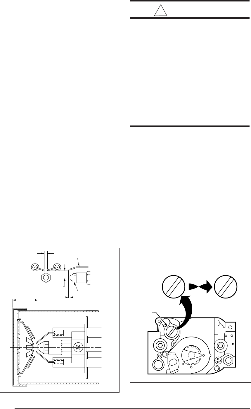
pressure regulator can be adjusted by re-
moving the regulator selector stack and
turning the slotted insert located directly
under the selector stack. The regulator
selector stack must be secured in place
before each pressure reading is taken.
Natural gas manifold pressure should be 3.5"
W.C. and L.P. gas manifold pressure should
be 10" W.C. Replace the gas pressure tap
plug on the gas valve.
b. Pilot Flame (Standing Pilot Only)
The pilot flame can be adjusted by turning the
pilot adjustment screw, located on top of the
gas valve (See Figure 29). The pilot flame
height should be between 3/4” and 1.” The
flame tip should be visible just above the pilot
bracket when viewed through the observa-
tion door. The same pilot orifice is used with
both natural and L.P. gas.
COMBUSTION AIR
In order for the flame to burn efficiently, it must
receive adequate combustion air. The amount
of combustion air required will vary depending
on altitude, actual B.T.U. content of the fuel
being used, gas pressure, conversion to an-
other gas and other factors. The burner flame
should be observed and any necessary adjust-
ments made before the furnace is placed into
service. See Table 9 for Factory Air settings.
Gas Gun
Combustion air box adjustment is made to the
main burner by loosening the two lock nuts on
the plastic air shutter, located on the left side of
the burner blower housing. Air shutter adjust-
ment line is located on the same side of the
blower housing. Turn the plastic shutter to a
smaller number (counter clockwise) for less air
to a larger number (clockwise) for more air.
Table 9. Factory Combustion Air
Settings
Model Nat. Gas LP Gas Oil
66,000 3.5 3.5 3
86,000 5.3 6 5
26
5/32” GAP
ELECTRODE
NOZZLE
0-1/16”
5/16” ABOVE CL
Gently tighten the lock nuts after completing the
adjustment. For best results, use instrument to
measure between 8-9% CO2, after the com-
bustion air has been adjusted. Note: Do not
over-tighten the lock nuts, otherwise the plastic
air shutter may be damaged.
Oil Gun Only
It is recommended that the CO2 and Smoke
levels should be measured for maximum per-
formance. CO2 readings should be 10-11% for
66,000 BTUH furnaces and 12-13% for 86,000
BTUH furnaces. The Smoke should be N0. 0 on
the Bacharach Scale, and 0 to 0.02 negative
draft over fire.
Electrode Setting (Oil Gun Only)
Poor ignition of the oil spray may result if the
electrodes are not adjusted as shown in Figure
32. Do not permit any electrodes to be grounded
to any surface.
Switching the Honeywell R7184 Ignition
Control between Interrupted and Intermit-
tent Duty (Oil Gun Only)
The Honeywell oil primary control can be
switched between interrupted and intermittent
ignition control. To switch from interrupted duty
(Factory set) to intermittent duty, remove the
igniter wire from the blue control wire. Attach the
burner motor and igniter wire to the orange
control wire. Cap and reseal the orange control
wire. Cap and isolate the blue control wire.
! CAUTION:
• Combustion air adjustment must be
made only by a qualified technician.
Improper air adjustment may cause
unsafe operation, explosion and/or
fire asphyxiation.
• If the input to the furnace is too great
because of excessive gas pressure,
wrong size nozzle or orifice, high alti-
tude, etc., the burner flame will be
sooty and can produce carbon mon-
oxide, which could result in unsafe
operation, explosion and/or fire or
asphyxiation.
GAS CONVERSION
This gas fired heating appliance was shipped
from the factory for use with natural gas. How-
ever, the appliance can be converted for use
with LP gas. Use the following procedure for
gas conversion of the burner.
ATMOSPHERIC AND DIRECT IGNITION
FURNACES
a. Follow the instructions to “Turn Off Gas to the
Appliance.”
b. Disconnect the gas pipe union and the elec-
trical wires connected to the gas valve.
c. Remove the pilot tube and thermocouple
from the gas valve (M1G*).
1 3/8”
Figure 32. Oil Gun electrode Position Figure 33. Convertible Pressure
Regulator Cap
PRESSURE
REGULATOR
CAP
M11678
N
A
T
N
A
T
L
P
L
P
N
A
T
N
A
T
OR
OTHER SIDE
OF CAP
Honeywell
Valve
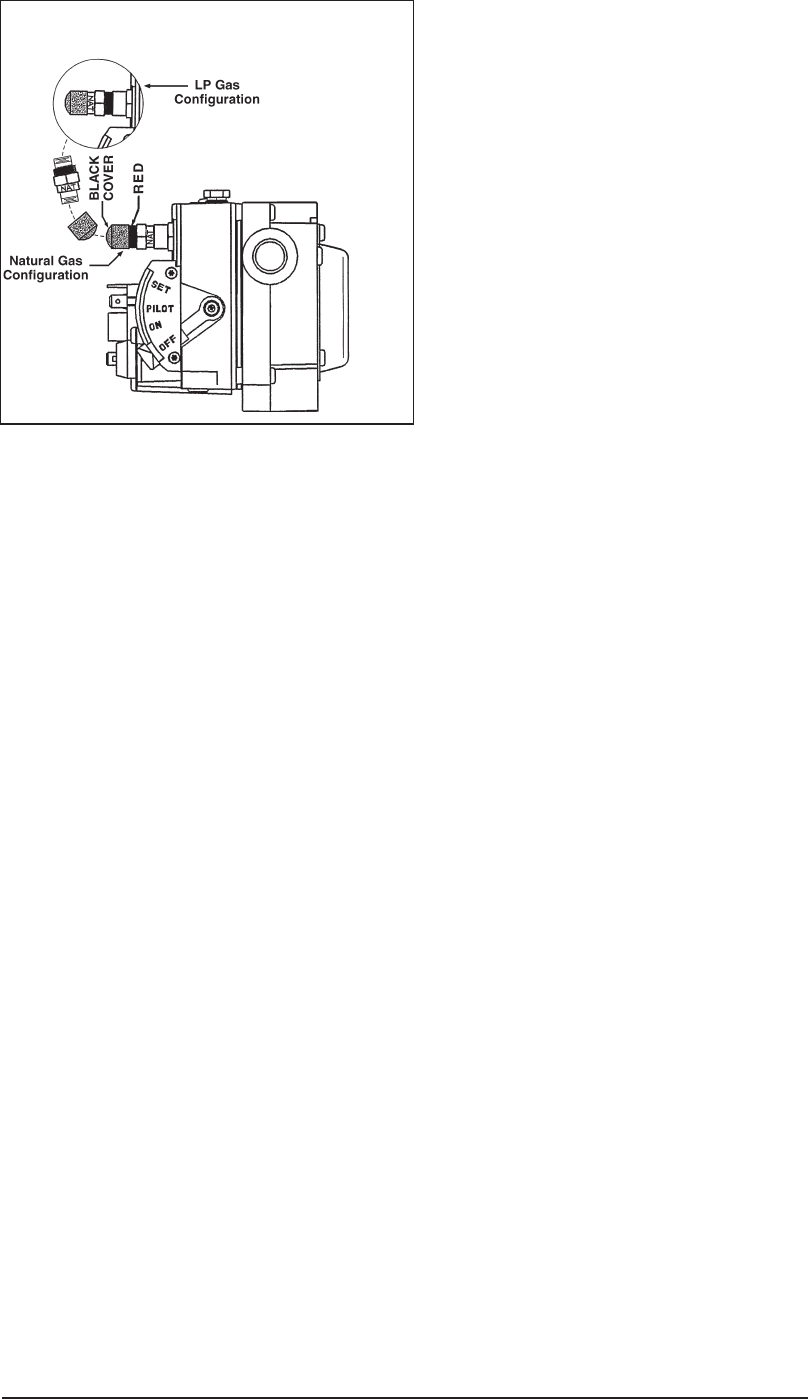
27
d. To remove the gas valve assembly, remove
screw(s) from gas valve bracket. Gas valve
and spud may be removed. Orifice is located
at the end of the spud (M1G*,M1M*),or re-
move three (3) bolts from U-shaped manifold
plate and orifice assembly (M1B*).
e. Replace the main orifice with the L.P. gas
orifice supplied in the envelope located by the
gas valve. Check to insure the orifice size
matches the nameplate.
f. It is not necessary to convert the pilot orifice.
g. For Honeywell gas valves with the regulator
converter (Figure 33), check for the letters
NAT or LP on the pressure regulator cap.
Unscrew the cap, invert it, replace, and
tighten until snug.
h. For the Robertshaw gas valve with the regu-
lator converter (Figure 34), remove the black
cover and unscrew the converter located on
top of the gas valve. Invert the converter.
(For “LP” the red ring will be located at the
bottom and the “LP” stamping on the con-
verter will appear right side up.) Then screw
converter back into the regulator, hand tight
plus 1/8 turn, and replace the black cover
onto the converter top to protect the threads.
i. Reassemble the burner assembly into the
furnace.
j. Reconnect the gas piping and electrical wires
to the gas valve.
k. Open the manual shut-off valve and follow
the FURNACE START-UP procedure as
outlined previously in this manual to put the
furnace into operation.
NOTE: The pilot flame is adjustable by turning
the adjustment screw located on the gas valve
with a small screwdriver. (See Figure 29)
TROUBLESHOOTING - STANDING PILOT
MODELS
Main Burner Does Not Come On
a. Check the electrical supply to the furnace.
b. Be sure the furnace On-Off switch is in the
“ON” position.
c. Check for proper thermostat operation.
d. Check for broken or open thermostat wires.
e. Check to make sure the insulation located on
the inside of the front panel is glued securely
around the fan switch and the limit switch.
f. Shut off the electrical supply to the furnace
and remove the electrical box cover.
g. Check for a defective transformer or blown
fuse.
h. Check electrical circuit for proper grounding,
polarity, and make sure the electrical con-
nections are tight.
i. Check to see if limit switches may have failed
to close.
j. Replace the electrical box cover and restore
electrical power to the furnace. Turn the On-
Off switch to “ON” and raise the thermostat
setting above room temperature.
k. Check for 24 volts at the gas valve.
l. Replace the gas valve if the pilot is estab-
lished and it does not open when powered
with 24 volts.
Gas Valve Powered (24 volts)– No Main
Flame
a. The manual shut-off valve must be on.
b. The pilot flame must be established.
c. The gas valve control lever must be in the
“ON” position.
d. Check gas pressure coming to the gas
valve.
e. Replace the gas valve if the main burner does
not come on under the above conditions.
Pilot Will Not Light or Goes Out
a. Check the incoming gas pressure.
b. Check for the proper pilot orifice. See the
nameplate SPECIFICATION.
c. Check for proper pilot flame adjustment. See
“BURNER ADJUSTMENTS.”
d. Check the thermocouple millivoltage.
• Millivoltage should read between 18 and 30
mv.
• If the closed millivolt reading is not between
18 and 30 mv., the gas valve electromagnet
Figure 34. Convertible Pressure
Regulator
Robertshaw
Valve

28
may be defective. Replace the gas valve if
necessary.
e. Be sure the pilot shield is in place.
f. Check for gas leaks in the pilot line or the pilot
assembly.
g. Check the flue assembly to make sure all
connections are tight.
h. See the FURNACE START-UP procedure
for lighting details.
Main Flame Is Not Burning Properly
a. Check the manifold gas pressure.
b. Check for the correct main burner orifice.
- See the nameplate SPECIFICATION.
Control Module Status Indicators - M1M Series
Control Status
The Red LED labeled “STATUS” is provided to indicate system faults.
Steady ON: Control OK
Steady OFF: No power
Rapid flash: False flame or internal control fault
One flash: Limit switch is open
Two flashes: Pressure switch is open
Three flashes: Pressure switch is stuck closed
Four flashes: Lockout due to failed ignition
Five flashes: L1 neutral reversed or L1 voltage
not present on L1
Flame Status
A Yellow LED labeled “Flame” is provided to indicate flame status. When
flame is sensed, the flame LED is lit. If flame sense is weak, yellow LED
will flash.
Control Module Status Indicator - M1S* Series
The indicator light on the oil primary control provides lockout, recycle,
and cad cell indications as follows:
1. Flashing 1/2 second on, 1/2 second off - system is locked out or
in restricted mode.
2. Flashing 2 seconds on, 2 seconds off - control is in recycle mode.
3. Indicator light is on - cad cell is sensing flame.
4. Indicator light is off - cad cell is not sensing flame.
c. Check the flue for any blockages or loose
connections.
d. Check the combustion air passages for block-
age.
High Gas Bills
a. Be sure the proper orifices are being used.
b. Be sure the return air system is clear and free
of blockage.
c. Be sure the furnace filter is clean.
d. Be sure the home is insulated, that windows
and doors fit tightly, and that there are no
leaks in the heating duct system.
e. Check the room thermostat to be sure the
setting is not higher than necessary. Low
Control Module Status Indicator - M1B
a. One flash-the control is in lock-out because the inducer centrifu
gal switch is or was stuck closed.
b. Two flashes-the control is in lockout because the signal was not
received by the control that the inducer centrifugal switch had
closed within the time.
c. Three flashes-the control is in lockout because a failed ignition
attempt, a gas valve error, or a false flame sensed during the warm
up period. If false flame has been sensed, the control will return to
normal operation, and repeat ignition sequence when the false flame
is not present.
d. Four flashes-the control is in lockout due to a failure within the control
board.

29
humidity requires higher temperatures for
the same level of comfort. Check for proper
humidity level in the home.
TROUBLESHOOTING -
DIRECT IGNITION FURNACES INCLUDING
GAS GUN
Burner Motor Does Not Run—
Thermostat Calls For Heat
a. Check the electrical supply to the furnace.
b. Be sure the furnace On-Off switch is in the
“ON” position.
c. Defective thermostat circuit - white and red
thermostat low voltage leads (M1M*, M1B*
models). If the burner motor or combustion
fan runs, check:
• Thermostat connections
• Thermostat
d. No voltage to control module - determine if 24
volts (or 120 volts) is available to the control
module. If voltage is not available check for:
• Blown fuse, defective transformer, circuit
breaker, no electrical supply.
• Limit switch open.
• Loose connections.
Combustion Blower Does Run - No Flame
a. Defective centrifugal switch (M1B* Model).
• Check the operation of centrifugal switch
by removing end bell of the burner motor.
• Clean contacts of motor.
• If the contacts are closed, replace the
motor.
b. Defective pressure switch (M1M* and M1G*
077, 090 Models) - check air tube and elec-
trical connections.
c. Burner in purge mode - allow 75 seconds for
flame establishing period.
d. Check for proper electrical connections at
purge timer, control box, or gas valve.
e. Check for gas supply - gas line valve on,
control lever on.
Control Module Is Powered—
Ignitor Does Not Heat Up
a. Disconnect ignitor leads at AMP receptacle
and check for 120 volts at the plug during
ignition sequence.
b. Replace ignition control if 120 volts is not
available at AMP plug during ignition se-
quence.
120 Volts Is Available At AMP Plug—
Ignitor Does Not Heat Up
a. Disconnect power to the furnace.
b. Disconnect AMP plug to the ignitor, and
check ignitor resistance with an ohm meter.
Set on RX1 scale.
• Normal reading should be 40 - 75 ohms.
• If above or below this rating at room tem-
perature change ignitor.
c. Check for continuity from ignitor receptacle
to burner.
Main Flame Ignites—
Burner Locks Out
a. Ignition control is not properly grounded.
b. Defective ignition control.
c. Improper polarity of 120 volt power supply.
d. Ignitor has hairline crack.
e. Improper gas pressure or burner air adjust-
ment is not allowing flame to contact ignitor tip
for flame rectification.
f. Misaligned ignitor does not allow flame to
contact ignitor tip for flame rectification.
Burner Short Cycling —-
Thermostat Calls for Heat, Limit Switches
Closed
a. Check for polarity.
b. Check ground.
c. Check flue.
d. Check combustion air.
e. Check gas pressure.
f. Check orifice.
g. Check the position of ignitor, a normal read-
ing should be 40-75 ohms.
24 Volts Supplied To Gas Valve During
Ignition —
No Main Gas Flow
a. Gas valve may be defective. Replace if
necessary.
b. Gas piping may be plugged. Check for
adequate gas supply to gas valve at union.
Burner Operates—
Insufficient Heat
a. Check thermostat for proper setting and
location. Thermostat should not be located
where it will be affected by another heat
source.
b. Check for clean filter and proper air flow.
c. Check burner for proper gas firing rate.
d. Be sure unit is not undersized for its thermal
load.
e. Check thermostat anticipator. The nominal
anticipator setting is 0.4.
Burner Flame Without Motor Running
a. Gas valve stuck open, check gas valve for
proper operation (replace if necessary) and
inspect heat exchanger.
b. Check for 115 volts to the combustion blower
motor; replace if necessary.
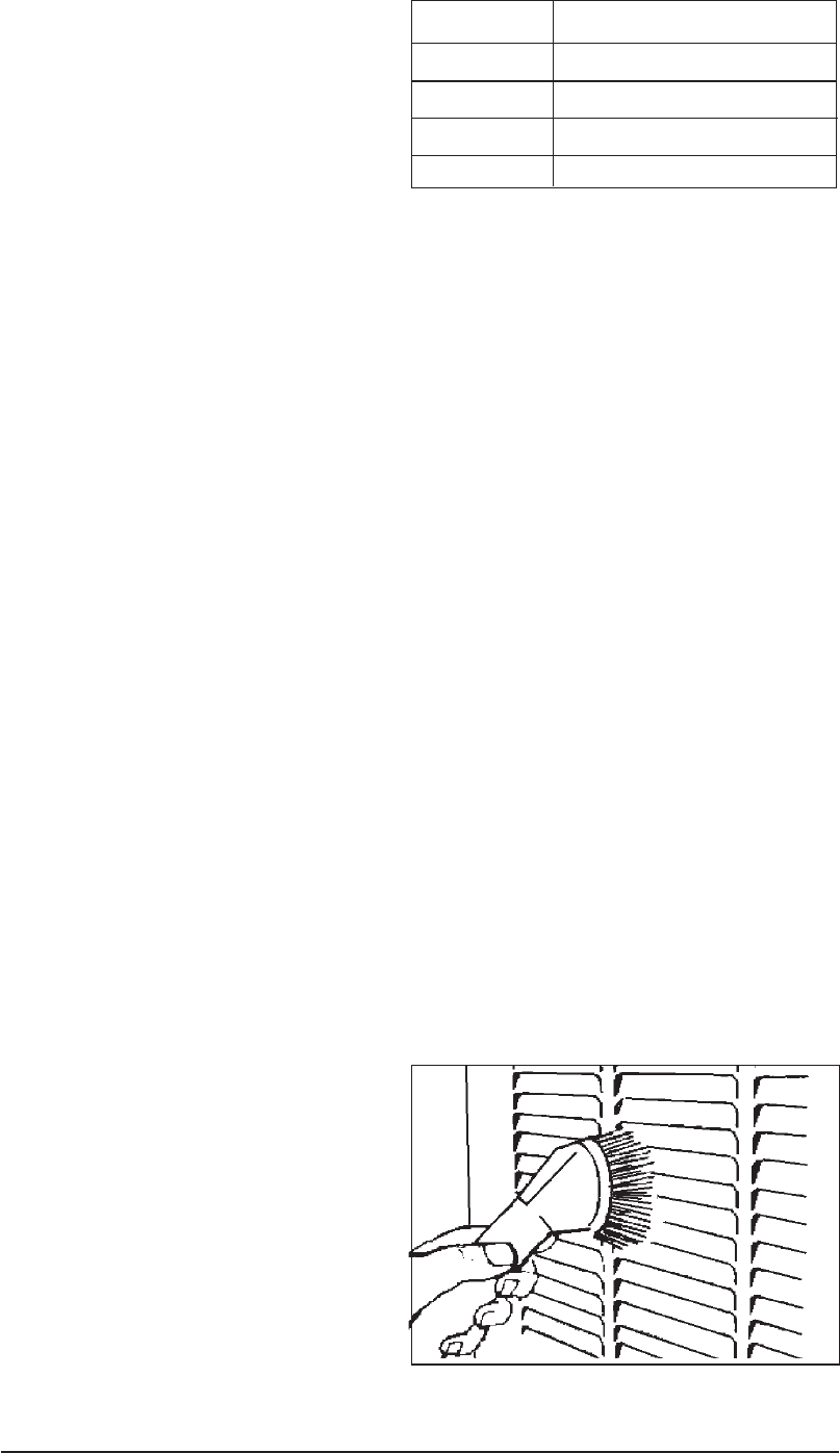
30
c. If no power to combustion blower then check
wiring and control module; replace if neces-
sary.
Circulation Air Blower Will Not Operate
Even Though The Burner Does Operate
a. Check thermostat “G” wiring.
b. Check wiring to motor.
c. Check for a defective motor.
TROUBLESHOOTING - OIL GUN
Honeywell R7184 oil gun control only.
Burner does not start with a call for heat.
1. Check the electrical supply to the furnace.
2. Be sure the furnace door switch is in the on
position.
3 Check for line voltage at the oil primary
control. The voltage should be 115 VAC.
4. Check indicator light with burner off, no call
for heat (no flame).
a. If indicator light is on, the cad cell is seeing
stray light or the cad cell or controller is
defective.
b. If indicator light is off, go to step 5.
c. If flashing, refer below (a. Reset primary
control).
5. Jumper T to T terminals on primary control.
a. If burner starts, check thermostat or limit
wiring connections.
b. If burner does not start, turn off power.
Check all wiring connections.
c. If burner does not start, replace R7184
control.
Burner starts, then locks out on safety with
indicator light flashing at
½
second on,
½
second off.
a. Reset primary control.
To reset the control from lockout, the button
needs only to be pressed and released. If it
is in restricted mode, the button should be
held in for 30 seconds (until the light flashes
twice, or until the light stops flashing on
earlier models).
Note: Restricted Mode: If the control
locks out three times in a row without a
complete heat cycle between attempts,
the lockout becomes restricted mode.
1. If indicator light stops flashing and
ignition remains off, primary control
could be defective. If line voltage is
present at the ignitor terminals, but
there is no ignition, the ignitor is probably
defective and needs to be replaced.
2. If indicator light stops flashing, burner
turns on, but control locks out again,
check cad cell if cad cell is Okay,
replace primary control.
3. If indicator light continues to flash at
1/2 second on, 1/2 second off, verify
that control is not in restricted mode. If
restricted mode, reset it. If not in re-
stricted mode, replace R7184.
4. If indicator light stays off while the flame
is on, check cad cell sighting for view
of flame.
5. If burner locks out, check cad cell
resistance. (See Table 10)
6. If burner keeps running, system is
Okay.
7. If indicator light is off, check cad cell
assembly after disconnecting line volt-
age power.
b. Burner will not start, and indicator light is
flashing at 2 second on, 2 second off.
Hold the reset button down for 1-2 second.
If indicator light continues to flash, wait for 60
- 70 seconds. If it still continues to flash,
replace the primary control.
c. To check cad cell resistance.
Press and release the button during the run
mode. The light will flash to indicate the cad
cell resistance. For proper burner operation,
it is important that the cad cell resistance
reaover 1600 Ohms. For cad cell resistance,
see Table 10.
Figure 35. Periodic Cleaning
Table 10. Cad Cell Resistance when
sensing flame
Led Flashes Cad Cell Resistance in Ohms
1 0 - 400
2 400 - 800
3 800 - 1,600
4 >1600
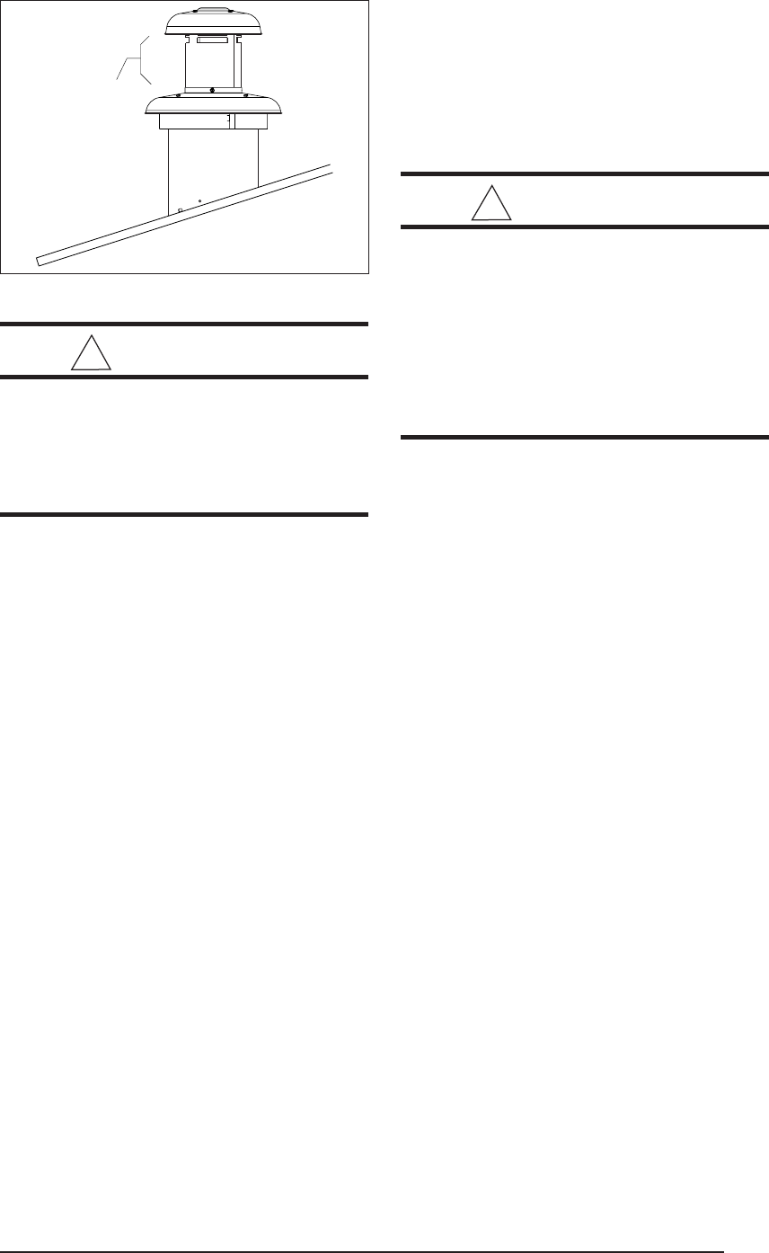
31
! WARNING:
Do not obstruct any return air open-
ings, including the grille on the fur-
nace. To do so may cause the furnace
to activate the high limit and shut down,
or it may cause asphyxiation.
18. MAINTENANCE
By Homeowner
1. Return Air - On some closet installations the
return air opening to the furnace may be on
the floor, on the door, on the side wall of the
closet, or some combination of these. The
upper grille on the front of the furnace admits
return air to the blower. Return air must be
provided back to the circulating blower in
order to provide air distribution.
2. Filters - At least twice each season (more
often in dusty areas) remove and clean the
air filters with a vacuum or with warm water
and soap. Reinstall when dry. Also clean
dust and lint around furnace and in the fur-
nace vestibule. (Figure 35.)
3. Seasonal Service Information - During ex-
tremely cold weather, ice may form on the
furnace roof jack. Small amounts of ice form-
ing on the roof jack will present no problems
to proper furnace operation. Excessive ice
formation could restrict the combustion air
supply to the burner, causing inefficient
burner operation. If excessive ice has formed
on the air inlet or exhaust portions of the roof
jack, it must be carefully removed (Figure
36).
By Serviceman
All furnaces need periodic service at the begin-
ning of each heating season. Call your service-
man to:
a. Remove the air circulator and clean all dust
and lint from the unit with a stiff bristle brush.
b. Inspect the combustion chamber blower
compartment, flue collar and Roof Jack.
c. Check the gas valve (if applicable) and fuel
line connections for leaks.
d. Make any adjustments necessary for good
operation.
! WARNING:
Use of furnace or air conditioning com-
ponents that are not included in the
certification of this appliance may cre-
ate a hazard, invalidate the certifica-
tion, and in many states, make instal-
lations illegal. Listed NORDYNE air
conditioning components are speci-
fied on the furnace label.
ADDITIONAL OIL
FURNACE MAINTENANCE
In addition to the preceding, the following should
be performed by a qualified service contractor
at least once each season for oil-fired furnaces:
a. Replace the oil nozzle with the type nozzle
specified for your furnace.
b. Clean, adjust and replace if necessary the
spark electrodes.
c. Reset the nozzle/drawer assembly to fac-
tory specifications.
d. Clean the inside of the furnace heat ex-
changer and replace the combustion liner if
necessary.
e. Clean or replace the oil filter element at the oil
tank.
f. Adjust the burner for top efficiency and check
to make sure all fittings are leak-tight.
19. OPTIONAL ACCESSORIES
Necessary when the Furnace is Used with
Some Central Air Conditioners
If an air conditioner is installed that does not use
the furnace blower for air distribution and that
operates independently of the furnace, the
thermostat system must have an interlock to
prevent the furnace and air conditioner from
operating at the same time. This interlock sys-
tem usually contains either a “Heat-Cool” switch
which must be turned to the “Heat” or “Cool”
position to activate either heating or cooling
operation, or a positive “OFF” switch on the
cooling thermostat.
Figure 36. Roof Jack
Check for
Ice Here
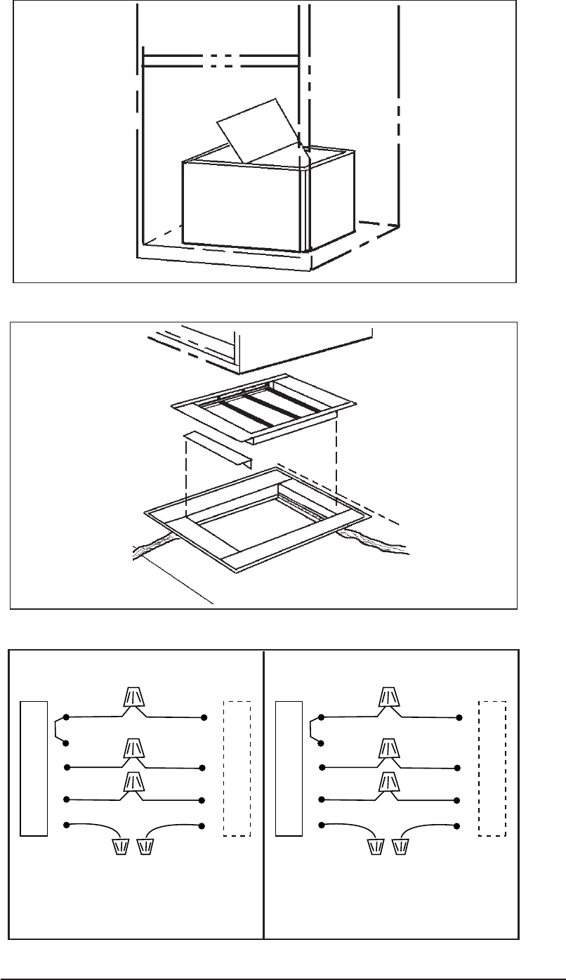
32
Figure 39. Thermostat Wiring A/C Ready Models
Figure 37. Coil Cavity Damper (Non-Platinum Series Only)
Figure 38. Damper without Coil Cavity (Non-Platinum Series Only)
Rc
R
H
W
G
Y
Red
White
Green
Yellow
Red
White
Green
Grey
**
Thermostat M1* A/C Ready
Furnace
Route Thermostat wire to intended Platinum
Series AC/HP location. Coil and secure extra
six feet of wire to home's undercarriage.
Platinum Ready Wiring
Rc
R
H
W
G
Y
Red
White
Green
Yellow
Red
White
Green
Grey
**
Thermostat M1* A/C Ready
Furnace
Standard Wiring

33
Table 11. A/C Blower Selection
Blower Speed Selection Chart for M1*C Models and
for use with Blower Kit No. 903413 1/2 Hp 4 Speed
Heating Cooling Speed/ Evap Coil
Speed 2-1/2 Ton
Furnace Input Setting & 3 Ton
077, 086, 090 ML L ML MH H
056, 066, 070 L L ML MH H
2 Ton 4 Ton
3-1/2
Ton
Blower Speed Selection Chart for M1*D Models and
for use with Blower Kit No. 903414 and 903890
3/4 Hp 4 Speed
Heating Cooling Speed/ Evap Coil
Furnace Input Speed 2-1/2 Ton 3-1/2 Ton
Setting & 3 Ton & 4 Ton
077, 086, 090 ML L ML MH H
056, 066, 070 L L ML MH H
2 Ton 5 Ton
The furnace must also be equipped with an
automatic damper (See Figures 37 or 38,
NORDYNE p/n 901996 for furnaces without coil
cavity, or p/n 901083 with coil cavity) to prevent
cold air from being discharged up around the
heat exchanger. Cold air may cause conden-
sation inside the heat exchanger which can lead
to rust and early failure.
OPTIONAL ADD-ON AIR CONDITIONING
Ask your dealer or contractor about NORDYNE
add-on central air conditioning systems. There
is a split-system or package air conditioner
designed for your total comfort needs. Whether
split system or single package, an energy-
saving NORDYNE unit is available that has
been designed specifically for manufactured
housing applications and can best handle your
home comfort needs.
Listed and ARI Certified, all models are pro-
tected by the NORDYNE Air Conditioner Lim-
ited Warranty.
Platinum series units are self contained pack-
age units with compressor and cooling coils.
They are designed as a drop in system when
used with the AC ready M1.
Single package unit includes cooling coils, com-
pressor, and vertical discharge fan. This type
of unit connects with the existing home air duct
system (an optional close-off damper is re-
quired with the furnace).
Split system unit with vertical discharge for quiet
operation connects with NORDYNE cooling
coil furnace (optional coil cavity required with
“A” model furnaces).
Blower Speed Selection Chart for M1*B Models and
for use with Blower Kit No. 903773 1/4 Hp 3 Speed
Heating Cooling Speed/ Evap Coil
Furnace Input Speed
Setting
086, 090 H L M H
066, 070, 077 M L M H
056 L L M H
2 Ton 3 Ton
2-1/2
Ton
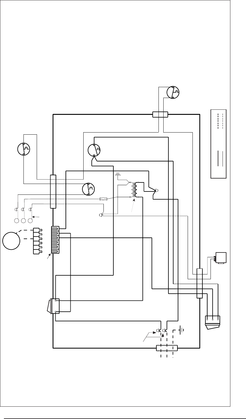
34
20. WIRING DIAGRAMS
703887B
Figure 40. Gas Atmospheric Furnace, M1GH 056, 070 Models
Gas Atmospheric Furnaces, M1GH 056, 070
ON/OFF
SWITCH
GAS VALVE
FAN SWITCH
HI-LIMIT
AUX. LIMIT
TRANSFORMER
L1 N
CR 24 V
115 V
WHITE
WHITE
WHITE
GRAY
BLUE
BLACK
GRAY
FAN ON/AUTO SWITCH
ORANGE
ORANGE
BLACK
L1
NEUTRAL
GROUND
SCREW
FURNACE ELECTRICAL BOX
BLACK
3A FUSE
BLOWER
MOTOR
HEATING
ONLY
654321
C
R
W
GRAY
RED
BLUE
CONNECTOR
HOUSING CAP
COMMON
FOR OPTIONAL
ACCESSORY KITS
BLACK
BLACK
LEGENDS
115V: FIELD 115V:
24V: FIELD 24V:
RED
NOTES
1. Incoming power must be polarized. Observe
color coding. (See furnace data label for
electrical information.)
2. If any of the original wires (as supplied with
the appliance) must be replaced, use 105˚C
Thermoplastic type wire or its equivalent.
BLACK
BLACK
SUPPLIED
BY INSTALLER
BLUE
WHITE
MANUAL RESET
VENT SWITCH

35
703888C
Figure 41. Standing Pilot with Induced Draft Furnace, M1GH 077, 090 Models
152
364
GAS VALVE
FAN
SWITCH
HI-LIMIT
AUX. LIMIT
PRESSURE
SWITCH
COMBUSTION
FAN
L1 N
CR 24 V
115 V
BLACK
BLACK
BLACK
BLUE
BLACK
WHITE
WHITE
WHITE
WHITE
GRAY
GRAY
BLUE
BLUE
21
GRAY
SUPPLIED BY
INSTALLER
FAN ON/AUTO
SWITCH
BLUE
BLACK
ORANGE
ORANGE
L1
NEUTRAL
GROUND
SCREW
FURNACE ELECTRICAL BOX
3A FUSE
BUSHING
RED
C
R
W
ON/OFF
SWITCH
CONNECTOR
HOUSING CAP
BLACK
BLACK
LEGENDS
115V: FIELD 115V:
24V: FIELD 24V:
GRAY
RED
WHITE
BLACK
BLACK
BLACK
TRANSFORMER
BLOWER
MOTOR
HEATING
ONLY
654321
BLACK
BLACK
NOTES
1. Incoming power must be polarized. Observe
color coding. (See furnace data label for
electrical information.)
2. If any of the original wires (as supplied with
the appliance) must be replaced, use 105˚C
Thermoplastic type wire or its equivalent.
Standing Pilot With Induced Draft Furnaces,
M1GH 077, 090 Models.
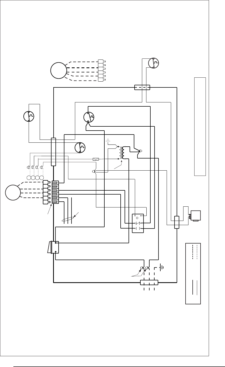
36
710150 08/00
Figure 42. Gas Atmospheric Furnace, A/C Ready, M1G (B, C, D) 056, 070 Models
RED (LOW)
BLACK (HIGH)
BLUE (MED. HI)
ORANGE (MED. LO)
152
A/C
BLOWER
RELAY
364
ON/OFF
SWITCH
GAS VALVE
FAN
SWITCH
HI-LIMIT
AUX. LIMIT
TRANSFORMER
L1 N
CR 24 V
115 V
BLACK
ORANGE
BLUE
ORANGE
GREEN
WHITE
WHITE
WHITE
BLACK
GRAY
BLUE
BLUE
BLACK
VENT SWITCH
BLUE
FURNACE ELECTRICAL BOX
L1
NEUTRAL
GROUND SCREW
C
R
G
W
HEATING/COOLING
RED
RED
(SEE NOTE)
TIE WIRE
CONNECTOR
HOUSING CAP
BLUE
GRAY
3A FUSE
GRAY
RED
654321
WHITE
SUPPLIED
BY INSTALLER
LEGENDS
115V: FIELD 115V:
24V: FIELD 24V:
NOTES
1. Incoming power must be polarized. Observe color
coding. (See furnace data label for electrical
information.)
2. If any of the original wires (as supplied with the
appliance) must be replaced, use 105˚C
Thermoplastic type wire or its equivalent.
BLOWER
MOTOR
4 SPEED
BLACK
BLACK
GRAY
GREEN
WHITE
MANUAL RESET
*
*M1G(C,D) Heating - replace orange wire with red wire (low speed)
M1GB 070 Heating - replace orange wire with blue
A/C & Heating Speeds: Refer to Table 10, A/C Blower Selection in the manual
NOTE: To run at same speed in both heating and cooling mode,
remove wire from either terminal 4 or 6 on the relay, then attach
jumper to terminals 4 and 6.
HEATING/
COOLING
654321
RED (LOW)
BLACK (HIGH)
BLUE (MED. HI)
WHITE
3 SPEED
BLOWER
MOTOR
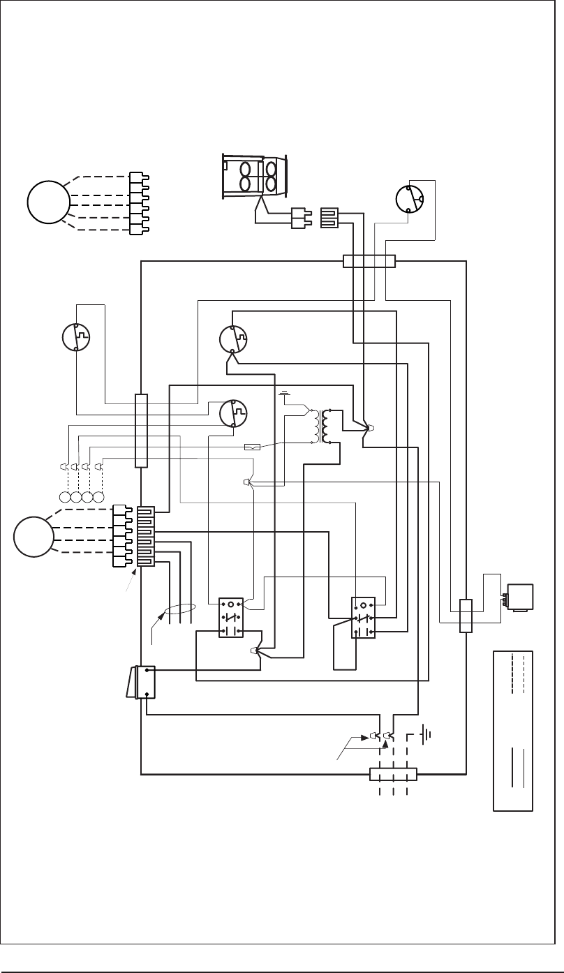
37
Figure 43. Standing Pilot with Induced Draft Furnace, A/C Ready M1G (B, C, D) 077, 090 Models
152
A/C
BLOWER
RELAY
364
152
COMBUSTION
BLOWER
RELAY
3
64
ON/OFF
SWITCH
GAS
VALVE
HI-LIMIT
AUX. LIMIT
TRANSFORMER
PRESSURE
SWITCH
COMBUSTION FAN
L1 N
CR 24 V
115 V
BLACK
BLACK
BLACK
BLACK
BLACK
ORANGE
ORANGE
GREEN
WHITE
WHITE
WHITE
WHITE
GRAY
GRAY
BLUE
BLUE
21
GRAY
L1
NEUTRAL
GROUND
SCREW
FURNACE ELECTRICAL BOX
RED
BLACK
BLUE
TIE WIRE
HEATING/
COOLING
BLUE
C
R
G
W
FAN
SWITCH
BLUE
RED* CONNECTOR
HOUSING
GRAY
3A FUSE
GREEN
LEGENDS
115V: FIELD 115V:
24V: FIELD 24V:
HEATING/COOLING
654321
RED (LOW)
BLACK (HIGH)
BLUE (MED. HI)
ORANGE (MED. LO)
WHITE
BLOWER
MOTOR
4 SPEED
CONNECTOR
HOUSING CAP
SUPPLIED
BY INSTALLER
* Jumper Wire - M1GB 090 Units Only
Otherwise Hi-Speed Connected
to Blower Relay (Black)
- M1GB 077 Heating: Orange wire
replaced by Blue
- M1GB 090 Heating: Orange wire
replaced by Black
GRAY
RED
GREEN
WHITE
BLACK
BLACK
RED
NOTES
1. Incoming power must be polarized.
Observe color coding. (See furnace
data label for electrical information.)
2. If any of the original wires (as supplied
with the appliance) must be replaced,
use 105˚C Thermoplastic type wire or
its equivalent.
654321
RED (LOW)
BLACK (HIGH)
BLUE (MED. HI)
WHITE
3 SPEED
BLOWER
MOTOR
A/C & Heating Speeds: Refer to
Table 10, A/C Blower Selection
in the manual
710151 08/00
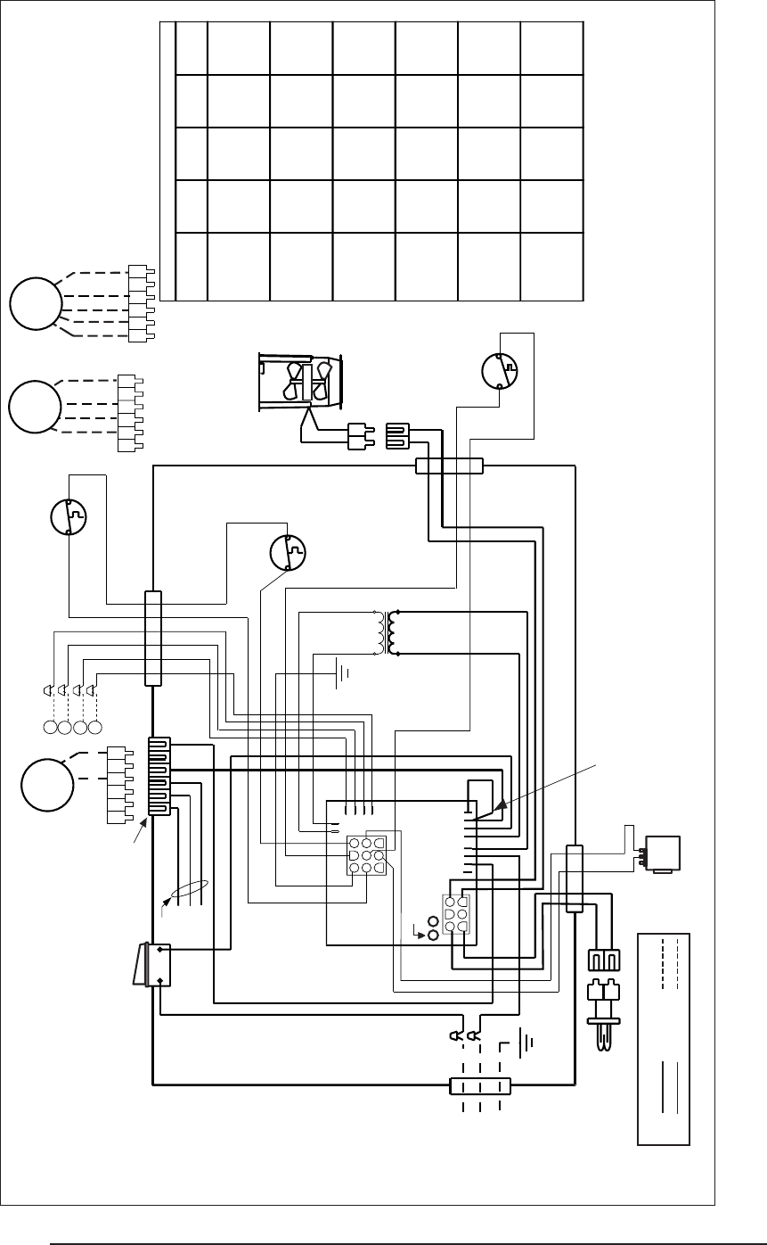
38
See Table
BLOWER
MOTOR
SINGLE
SPEED
ON/OFF
SWITCH
C
R
G
W
GAS VALVE
HI-LIMIT
AUX. LIMIT
TRANS-
FORMER
PRESSURE
SWITCH
654321
654321
COMBUSTION FAN
L1 N
CR
24 V
115 V
21
1
4
5
2
6
3
1
2
3
4
5
6
7
8
9
IGNITOR
BLUE
BLUE
BLACK
GREEN
YELLOW
YELLOW
BLACK
BLACK
ORANGE
ORANGE
BLACK WHITE
L1
NEUTRAL
GROUND SCREW
FURNACE ELECTRICAL BOX
24V
NEU
C
H
L1
XFRM
TIE
WIRE
See Table
CONNECTOR
HOUSING CAP
GROUND
SCREW
BLACK
BLACK
CONTROL LIGHT STATUS
RED YELLOW
Steady ON Control OK Steady ON Good Flame Signal
Steady OFF No power Blinking Weak Flame Signal
Rapid Flash False flame or internal control fault Steady OFF No Flame Signal
1 Flash Limit switch is open
2 Flashes Pressure switch is open with inducer on
3 Flashes Pressure switch is closed with inducer off
4 Flashes Lockout due to failed ignition
5 Flashes 115 vac & neutral reversed or no ground
CONTROL
LIGHTS
RED
Jumper must be removed if
converting to a multispeed blower.
Jumper is required for M1MA
models and M1MB 090
A/C & Heating Speeds: Refer to
Table 10, A/C Blower Selection
in the manual
BLACK
WHITE
WHITE
BLACK
BLACK
GREEN
RED
GRAY
WHITE
RED (LO)
BLACK (HIGH)
BLUE (MED. HI)
ORANGE (MED. LO)
WHITE
RED (LO)
BLACK (HIGH)
BLUE (MED. HI)
WHITE
654321
LEGENDS
115V: FIELD 115V:
24V: FIELD 24V:
BLOWER
MOTOR
4 SPEED
NOTES
1. Incoming power must be polarized. Observe color
coding. (See furnace data label for electrical
information.)
2. If any of the original wires (as supplied with the
appliance) must be replaced, use 105˚C Thermoplastic
type wire or its equivalent.
SUPPLIED
BY INSTALLER
C W G R
COM
BLUE
BLOWER
MOTOR
3 SPEED
See Table
See Table
710152 07/01
Figure 44. Gas Direct Ignition Furnace, Heating & A/C Ready - All M1M Models
Blower Wire Table
Blower Wire Connections
Furnace Wire #1
Wire #2 Wire #3 Wire #4
Model Red
Black Blue Orange
M1MA 056/
Tie Tie Tie Control
070/077/090
Wrapped Wrapped Wrapped
Board "H"
M1MB
Tie Control Tie Control
056
Wrapped Board "C" Wrapped Board "H"
M1MB
Tie Tie Control Control
070/077
Wrapped Wrapped Board "H" Board "C"
M1MB
Tie Control Tie Tie
90
Wrapped Board "H" Wrapped Wrapped
M1M(C,D)
Control Tie Tie Control
056/070
Board "H" Wrapped Wrapped Board "C"
M1M(C,D)
Tie Tie Tie Control
077/090
Wrapped Wrapped Wrapped Board "H"
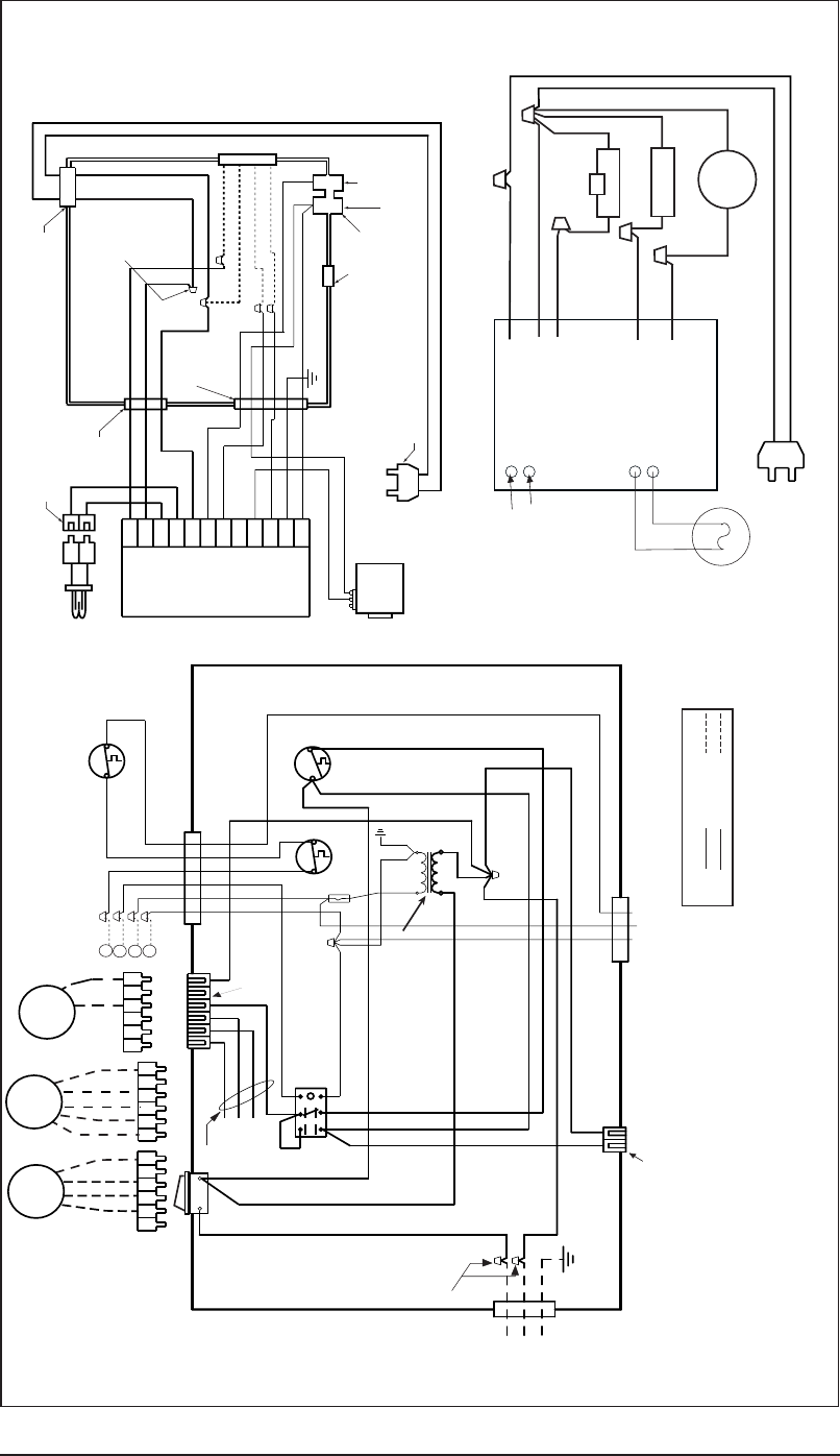
39
7104670 04/04
Figure 45. Gas and Oil Furnaces, A/C Ready - M1 (B, S) 066, 086 Models
152
A/C
BLOWER
RELAY
364
FAN
SWITCH
HI-LIMIT
AUX. LIMIT
TRANSFORMER
L1 N
CR 24 V
115 V
BLACK
GREEN
WHITE
WHITE
WHITE
GRAY
BLUE
GRAY
BLUE
BLACK
BLACK
CRW
BLUE
BLACK
ORANGE
ORANGE
L1
NEUTRAL
GROUND
SCREW FURNACE
ELECTRICAL BOX
RED
TIE WIRE
WHITE
RED 3A FUSE
GRAY
RED
GREEN
WHITE
654321
654321
RED (LO)
BLACK (HIGH)
BLUE (MED. HI)
WHITE
4 SPEED
BLOWER
MOTOR
SINGLE
SPEED
BLOWER
MOTOR
C
R
G
W
ON/OFF
SWITCH
BUSHING
BUSHING
BLACK
RED
(SEE NOTE 3)
RECEPTACLE
NOTES
1. Incoming power must be polarized. Observe color coding
(See furnace data label for electrical information.)
2. If any of the original wires (as supplied with the appliance) must
be replaced, use 105˚C Thermoplastic type wire or its equivalent.
3. On models M1(B,S)A and M1(B,S)086 jumper wire is installed.
On all other models, cooling speed is connected to black wire.
4. A/C & Heating Speeds: Refer to Table 10, A/C Blower Selection
in manual.
5 If any of the original wire supplied with the appliance is replaced, use
105˚C wire or equivalent.
6. Use copper conductors only.
LEGENDS
115V: FIELD 115V:
24V: FIELD 24V:
GRAY
RED
GREEN
CONNECTOR
HOUSING CAP
BLACK
BLACK
LINE CORD
T1
T2
F1
F2
FROM 'R' WIRE (RED)
FROM 'W' WIRE (BLUE)
CAD CELL
PRIMARY CONTROL
BLACK
BLACK
IGNITION MODULE
BURNER MOTOR
BLACK
WHITE
VIOLET
BLACK
WHITE
VIOLET
WHITE
R7184B
PRIMARY
CONTROL
SUPPLIED
BY INSTALLER
BLACK
654321
RED (LO)
BLUE (MEDHI)
BLACK (HI)
WHITE
3 SPEED
BLOWER
MOTOR
ORANGE (MED LO)
NL1
BURNER ELECTRICAL BOX
GAS VALVE
IGNITER
GREEN
BLUE
BLUE
BLACK
WHITE
RED
RED
RED
BLACK
GROUND SCREW
BLACK
BLACK
RED
RED
BLACK
BLACK
GRAY
GV
PSO
FSG
C
IND
L1
HSI
HSIG
L2
W
PSI
FSI
CONTROL
MODULE
TERMINAL HOUSING
BUSHING
LINE CORD
(ITEM #12)
TERMINAL
BUSHING
BUSHING
BUSHING
BUSHING
WC
ITEM #10
(TYP. 5)
FROM "C"
WIRE - GRAY
BLACK
BLACK
FROM "W"
WIRE - BLUE
GAS GUN BURNER
ORANGE
WHITE
SOLENOID
VALVE
BLUE
BLUE
OIL GUN BURNER
¢708672;¤
7086720
O’Fallon, MO
7086720 (Replaces 708074E)
Specifications and illustrations subject to change
without notice and without incurring obligations.
Printed in U.S.A. (12/06)
INSTALLER: Please leave
these installation instructions
with the homeowner.
21. EQUIVALENT ORIFICE SIZES AT HIGH ALTITUDES
(Includes 4% Input Reduction for Each 1,000 Feet)
Reference Sources: ANSI Z233.1 & NFPA 54, National Fuel Gas Code.
For Canadian high altitude (2,000 - 4,500'), reduce gas manifold pressure to 3.0”
W.C. for
natural gas and 9” W.C. for LP gas.
NOTE: Do not attempt to change the size of an orifice by drilling it out. To do so will
void the manufacturer’s warranty
Table 12. High Altitude
FURNACE ORIFICE SIZE AND ALTITUDE - FEET
MODEL OUTPUT CAPACITY SEA LEVEL 2000 3000 4000 5000 6000 7000 8000 9000 10000
ORIFICE SIZE - NAT. GAS 29 293030303031313132
M1M/G 056 ORIFICE SIZE - LP 45 46 47 47 47 48 48 49 49 50
OUTPUT- MBTUH 45.4 41.8 40.1 38.5 37.0 35.5 34.1 32.7 31.4 30.2
ORIFICE SIZE - NAT. GAS 24 252627272828292930
M1M/G 070 ORIFICE SIZE - LP 42 42 43 43 43 44 44 45 46 47
OUTPUT- MBTUH 56.7 52.3 50.2 48.2 46.2 44.4 42.6 40.9 39.3 37.7
ORIFICE SIZE - NAT. GAS 21 232324252627282829
M1M 077 ORIFICE SIZE - LP 40 41 42 42 42 43 43 44 44 45
OUTPUT- MBTUH 61.7 56.9 54.6 52.4 50.3 48.3 46.4 44.5 42.7 41.0
ORIFICE SIZE - NAT. GAS 21 232324252627282829
M1G 077 ORIFICE SIZE - LP 40 41 42 42 42 43 43 44 44 45
OUTPUT- MBTUH 59.9 55.2 53.0 50.9 48.9 46.9 45.0 43.2 41.5 39.8
ORIFICE SIZE - NAT. GAS 17 181919202122232426
M1M 090 ORIFICE SIZE - LP 36 37 38 38 39 40 41 41 42 43
OUTPUT- MBTUH 71.7 66.1 63.5 60.9 58.5 56.1 53.9 51.7 49.7 47.7
ORIFICE SIZE - NAT. GAS 17 181919202122232426
M1G 090 ORIFICE SIZE - LP 36 37 38 38 39 40 41 41 42 43
OUTPUT- MBTUH 69.7 64.2 61.7 59.2 56.8 54.6 52.4 50.3 48.3 46.3
ORIFICE SIZE - NAT. GAS 26 272828282929303030
M1B 066 ORIFICE SIZE - LP 43 44 44 44 45 45 46 47 47 48
OUTPUT- MBTUH 52.6 48.5 46.6 44.7 42.9 41.2 39.6 38.0 36.5 35.0
ORIFICE SIZE - NAT. GAS 18 191920212223242627
M1B 086 ORIFICE SIZE - LP 37 38 39 39 40 41 42 42 43 43
OUTPUT- MBTUH 68.2 62.9 60.3 57.9 55.6 53.4 51.2 49.2 47.2 45.3
