Nordyne G6Rc 90 Users Manual 707931 0 G6 90+ Furnace Ii.p65
G6RL 90+ to the manual 2ed0ecf7-171f-4ed3-80e8-6614f5e344df
2015-02-05
: Nordyne Nordyne-G6Rc-90-Users-Manual-404100 nordyne-g6rc-90-users-manual-404100 nordyne pdf
Open the PDF directly: View PDF ![]() .
.
Page Count: 36
Installation Instructions
These instructions are primarily intended to
assist qualified individuals experienced in
the proper installation of this appliance.
Some local codes require licensed installa-
tion/service personnel for this type of equip-
ment. Read all instructions carefully before
starting the installation.
DO NOT DESTROY. PLEASE READ CARE-
FULLY AND KEEP IN A SAFE PLACE FOR
FUTURE REFERENCE.
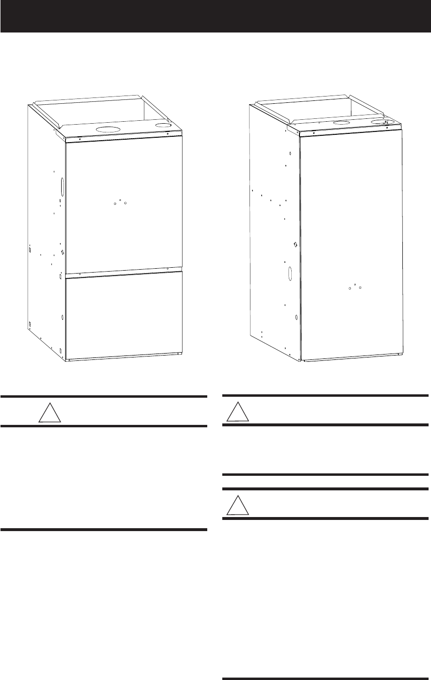
G6RC 90+, G6RD 93+ Upflow G6RL 90+ Downflow
G6RC Series 90+ Upflow Condensing Furnace
G6RD Series 93+ Upflow Condensing Furnace
G6RL Series 90+ Downflow Condensing Furnace
Residential Gas Furnaces
! WARNING:
Improper installation, adjustment, al-
teration, service, or maintenance can
cause injury or property damage. Re-
fer to this manual for assistance. For
additional information consult a quali-
fied installer, service agency, or the
gas supplier.
! FOR YOUR SAFETY:
Do not store or use gasoline or other
flammable vapors and liquids in the
vicinity of this or any other appliance.
! FOR YOUR SAFETY:
WHAT TO DO IF YOU SMELL GAS:
• Do not try to light any appliance.
• Do not touch any electrical switch; do
not use any phone in your building.
• Immediately call your gas supplier
from a neighbor's phone. Follow the
gas supplier's instructions.
• If you cannot reach your gas supplier,
call the fire department.
• Extinguish any open flame.
Table of Contents
Furnace Specifications ............................................................................................................ 4-5
Furnace Airflow Data .......................................................................................................... 6-7
Installation Requirements .......................................................................................................... 8
Supply Air Plenum Installation ..................................................................................................9
Installation on a Concrete Slab ............................................................................................. 9
Installation on a Combustible Floor....................................................................................... 9
Circulating Air Supply ............................................................................................................... 10
Return Air ............................................................................................................................ 11
Venting and Combustion Air Requirements .......................................................................... 11
Air Requirements for One-Pipe Installation ........................................................................ 13
Installation in An Unconfined Space ................................................................................... 13
Installation in A Confined Space ......................................................................................... 13
• Air From Inside .................................................................................................................. 13
• Air Directly Through An Exterior Wall ............................................................................... 14
• Outdoor Air Through Vertical Openings or Ducts ............................................................. 14
• Outdoor Air Through Horizontal Openings or Ducts ......................................................... 14
Venting Requirements .............................................................................................................. 14
Vent Pipe Material ............................................................................................................... 14
Vent Pipe Length and Diameter .......................................................................................... 14
Vent Pipe Installation ..........................................................................................................15
Pipe Routing & Support ....................................................................................................... 15
Location of Outdoor Terminations ....................................................................................... 18
Horizontal Venting ............................................................................................................... 19
Vertical Venting ................................................................................................................... 20
Vent Freezing Protection ..................................................................................................... 20
Concentric Vent Termination ............................................................................................... 20
Drainage of Condensate From Furnace ................................................................................. 21
Gas Supply and Piping ........................................................................................................ 22
Leak Check .......................................................................................................................... 22
Conversion........................................................................................................................... 23
High Altitude Application ..................................................................................................... 23
Natural Gas High Altitude Conversion ................................................................................ 23
LP/Propane Gas Sea Level and High Altitude Conversion ................................................ 23
Electrical Wiring ........................................................................................................................ 24
Line Voltage Wiring .............................................................................................................24
Low Voltage Wiring ............................................................................................................. 25
Start-up and Adjustments......................................................................................................... 25
Start-Up Procedure..............................................................................................................26
Verifying and Adjusting Firing Rate ..................................................................................... 26
Verifying and Adjusting Temperature Rise ......................................................................... 27
Verifying Burner Operation .................................................................................................. 27
Verifying Operation of the Supply Air Limit Switch ............................................................. 29
Description of Components ..................................................................................................... 29
Maintenance ............................................................................................................................... 31
Combustion Air and Vent System ....................................................................................... 31
Air Filter(s) ........................................................................................................................... 31
Lubrication ........................................................................................................................... 31
Condensate Drain Assembly ............................................................................................... 31
Blower Compartment ........................................................................................................... 31
Heat Exchanger and Burner Maintenance .......................................................................... 31
Location of Major Components ........................................................................................... 32
System Operation Information ................................................................................................. 31
Sequence of Operation ....................................................................................................... 33
Furnace Fails to Operate .................................................................................................... 34
Twinning of Two Furnaces .................................................................................................. 34
Installation/Performance Checklist ......................................................................................... 35
4
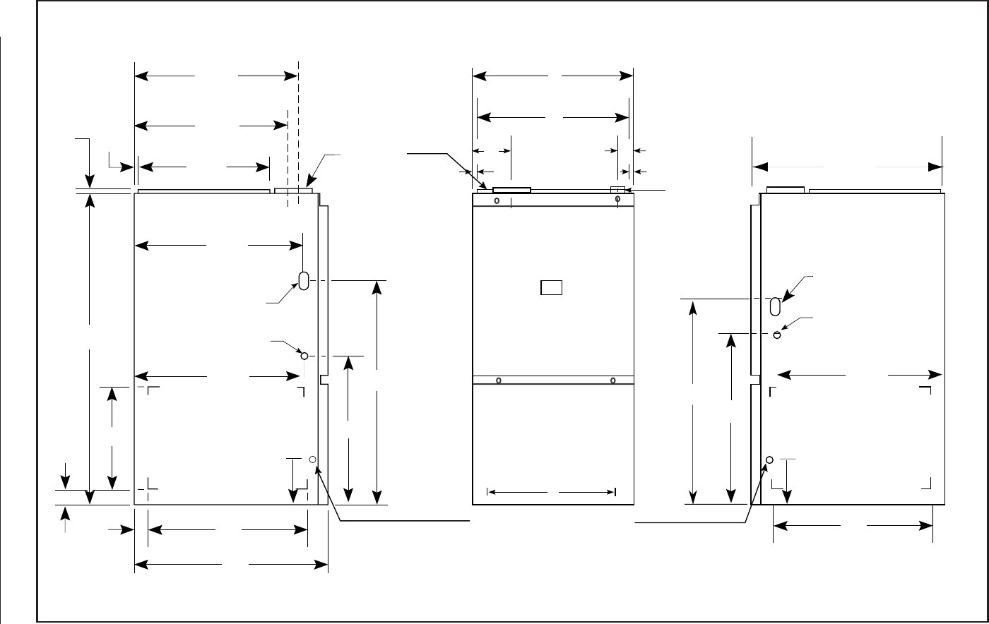
FURNACE SPECIFICATIONS
7/8" Dia. Electric
Connection
2 1/4"
23 1/4"
19 3/4"
3/4"
43"
25 1/8"
25 1/4"
23"
28"
15"
25 1/4"
33"
Return Air Opening
(Bottom)
Return Air Opening
(Side)
Bottom Return Opening
Condensate Drain Outlets
A
B
Combustion Air
Vent
(See Fig. 15
for sizes)
1 1/2" x 3 1/2" Dia.
Opening for
Gas Connection
+
3/4" 3/4"
3/4" 22 1/2"
Exhaust Vent
Combustion Air
Inlet
1 1/2" x 3 1/2" Dia.
Opening for
Gas Connection
C
2" PVC
Exhaust
Vent
(See Fig. 15
for sizes)
25 5/8"
20 1/2"
23"
+
7/8" Dia. Electric
Connection
30 1/4"
8"
8"
1 1/4"
1" D
27 5/8"
Upflow G6RC & G6RD Furnaces
Figure 1. G6RC, G6RD Unit Dimensions
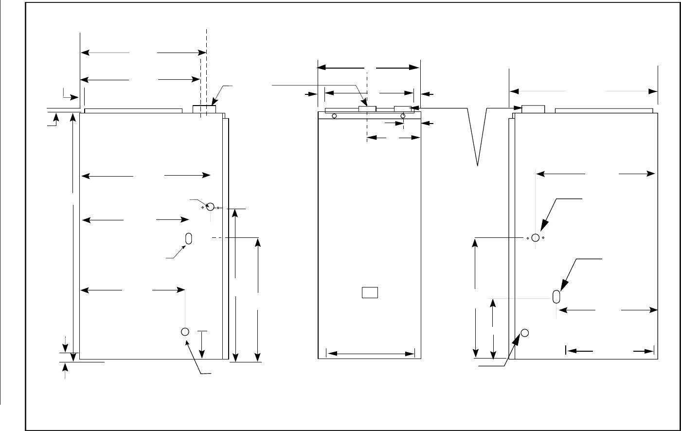
5
3/4" 3/4"
2 1/2"
Combusting
Vent
(3" for 80/100
2" for 40/60)
L
C
A
C
D
B
Condensate
Drain
Outlet
Condensate
Drain
Outlet
7/8" Dia.
Electric
Connection
1 1/2" x 2 1/2"
Knockout
For Gas
Connection
Bottom Opening
27 7/8"
19 3/4"
7/8" Dia. Electric
Connection
24 1/2"
3/4"
43"
21 7/8"
21 1/2"
15 1/2" 21 1/2"
10 1/4"
Bottom Supply Air Opening
(Side)
Exhaust
Vent
2"
1 1/2" x 3 1/2" Dia.
Opening for
Gas Connection
3/4"
22 1/2"
Exhaust Vent
Combustion Air Inlet
24 7/8" 24 7/8"
21 7/8"
21 1/4"
8"
1"
Downflow G6RL Furnace
Figure 2. G6RL Unit Dimensions
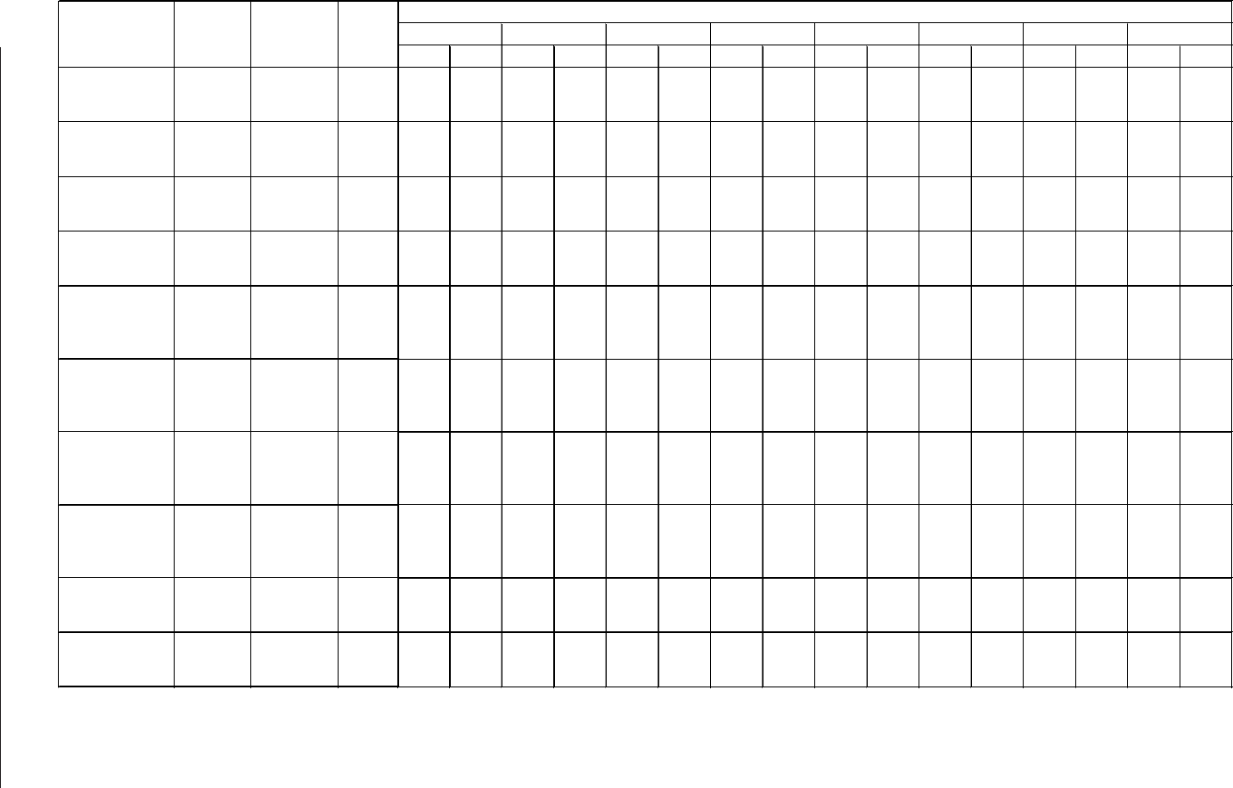
6
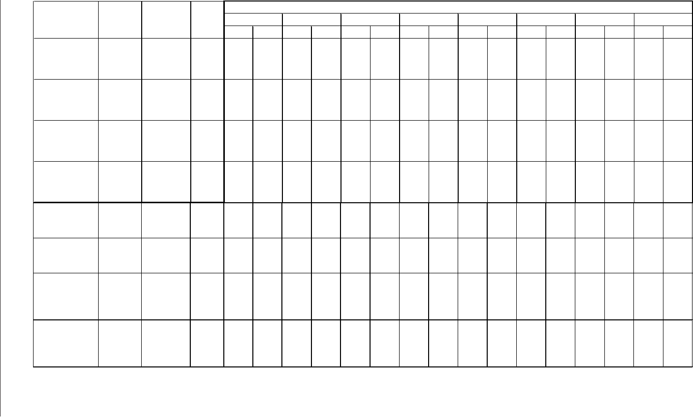
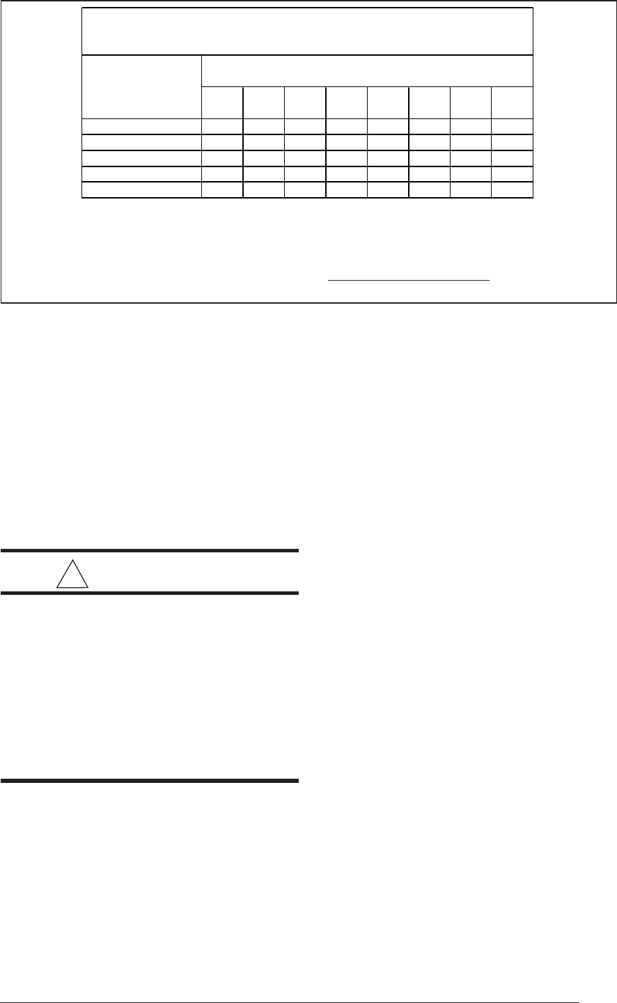
Table 1. Furnace Airflow Data
CAPACITIES —Furnace Airflow Data
External Static Pressure (Inches Water Column)
0.1 0.2 0.3 0.4 0.5 0.6 0.7 0.8
CFM Rise CFM Rise CFM Rise CFM Rise CFM Rise CFM Rise CFM Rise CFM Rise
950 36 920 38 890 39 850 41 800 43 750 46 690 50 630 55
740 47 710 49 680 51 650 53 600 58 550 63 490 - 430 -
620 56 590 59 560 62 520 - 470 - 410 - 350 - 290 -
1330 - 1280 - 1230 -
1170
- 1120 - 1030 - 940 37 850 41
1190 - 1160 - 1110 -
1060
- 1010 - 910 38 820 42 720 48
830 42 810 43 780 44 760 46 720 48 670 52 610 57 550 63
1310 - 1260 - 1210 -
1160
45 1100 47 1040 50 980 53 920 56
1160 45 1120 46 1080 48
1050
49 990 52 940 55 890 58 830 63
800 65 780 67 760 68 740 70 710 73 680 - 650 - 620 -
1490 46 1450 48 1390 50
1310
53 1210 57 1100 63 980 - 830 -
1230 56 1200 58 1150 60
1080
64 1010 69 910 - 810 - 680 -
780 - 750 - 720 - 680 - 630 - 570 - 510 - 440 -
1840 - 1780 - 1700 41
1630
42 1550 45 1470 47 1380 50 1290 54
1600 43 1560 44 1470 47
1400
49 1350 51 1280 54 1210 57 1150 60
1380 50 1350 51 1300 53
1250
55 1190 58 1120 62 1040 67 960 -
1100 - 1050 - 1000 - 950 - 900 - 850 - 800 - 750 -
1910 45 1860 47 1780 49
1700
51 1620 53 1520 57 1420 61 1310 66
1640 53 1620 53 1540 56
1480
58 1420 61 1340 65 1250 69 1150 75
1440 60 1410 61 1370 63
1320
66 1270 68 1210 72 1140 - 1060 -
1230 - 1210 - 1180 -
1140
- 1090 - 1030 - 960 - 880 -
1860 56 1800 58 1730 60
1650
63 1570 66 1480 70 1380 75 1270 82
1650 63 1610 65 1550 67
1480
70 1410 74 1320 79 1230 84 1120 -
1440 72 1410 74 1380 75
1320
79 1280 81 1220 85 1150 - 1080 -
1230 - 1210 - 1180 -
1140
- 1090 - 1030 - 960 - 880 -
2260 - 2200 - 2140 -
2070
- 1990 - 1910 - 1810 57 1710 61
1870 56 1840 56 1790 58
1760
59 1710 61 1660 63 1610 65 1560 67
1540 67 1530 68 1510 69
1470
71 1430 73 1370 76 1300 80 1220 85
1360 - 1330 - 1310 -
1280
- 1250 - 1220 - 1190 - 1150 -
1050 - 1005 - 960 - 915 - 855 - 800 - 730 48 670 53
990 - 950 - 905 - 860 - 810 - 760 46 700 50 650 54
770 46 740 48 700 50 660 53 625 56 580 61 540 65 500 70
1175 45 1125 47 1075 49
1030
51 970 54 920 57 860 61 800 66
1075 49 1040 51 995 53 950 56 900 59 840 63 790 67 720 73
800 66 770 69 745 71 710 74 670 - 630 - 580 - 530 -
Heating
Model Input Motor Motor
Number (Btuh) Speed HP
Hi
g
h*
G6RC040C-08
40,000 Medium 1/5
Low**
Hi
g
h*
G6RC040C-12
40,000 Medium 1/3
Low**
Hi
g
h*
G6RC060C-12
60,000 Medium 1/3
Low**
Hi
g
h*
G6RC080C-12
80,000 Medium 1/3
Low**
Hi
g
h*
G6RC080C-16
80,000
Med-High
1/2
Med-Low**
Low
Hi
g
h*
G6RC100C-16
100,000 Med-Hi
g
h** 1/2
Med-Low
Low
Hi
g
h*
G6RC120C-16
120,000 Med-Hi
g
h** 1/2
Med-Low
Low
Hi
g
h*
G6RC120C-20
120,000
Med-High
3/4
Med-Low**
Low
Hi
g
h*
G6RD040C-10
40,000 Medium 1/3
Low**
Hi
g
h*
G6RD060C-10
60,000 Medium** 1/3
Low
7
Table 2. Furnace Airflow Data
Heating
Model Input Motor Motor
Number (Btuh) Speed HP
Hi
g
h*
G6RD080C-14 80,000
Med-High
1/2
Med-Low**
Low
Hi
g
h*
G6RD100C-14 100,000 Med-Hi
g
h** 1/2
Med-Low
Low
Hi
g
h*
G6RD120C-14 120,000 Med-Hi
g
h** 1/2
Med-Low
Low
Hi
g
h*
G6RD120C-19 120,000
Med-High
3/4
Med-Low**
Low
External Static Pressure (Inches Water Column)
0.1 0.2 0.3 0.4 0.5 0.6 0.7 0.8
CFM Rise CFM Rise CFM Rise CFM Rise CFM Rise CFM Rise CFM Rise CFM Rise
1620 - 1560 45 1490 47
1430
49 1365 52 1300 54 1240 57 1170 60
1450 49 1400 50 1350 52
1295
54 1240 57 1180 60 1120 63 1060 66
1255 56 1225 57 1180 60
1145
61 1105 64 1060 66 1020 69 980 72
1080 65 1055 67 1030 68
1000
70 960 73 920 - 870 - 820 -
1620 54 1555 57 1485 59
1425
62 1355 65 1290 68 1220 72 1160 -
1430 62 1375 64 1330 66
1265
70 1210 73 1150 - 1080 - 1010 -
1260 70 1220 72 1170 75
1130
- 1070 - 1010 - 950 - 890 -
1085 - 1050 - 1015 - 970 - 935 - 890 - 850 - 800 -
1700 62 1635 65 1565 67
1500
70 1435 74 1370 77 1310 - 1240 -
1510 70 1455 73 1405 75
1350
78 1290 - 1230 - 1170 - 1100 -
1330 79 1280 - 1240 -
1195
- 1145 - 1100 - 1050 - 1000 -
1140 - 1110 - 1075 -
1040
- 1010 - 980 - 940 - 910 -
2140 - 2070 - 2010 -
1945
- 1870 56 1800 59 1730 61 1650 64
1955 - 1900 56 1850 57
1800
59 1740 61 1690 62 1630 65 1570 67
1660 64 1620 65 1575 67
1540
69 1495 71 1460 72 1410 75 1370 77
1450 73 1430 74 1400 75
1360
78 1340 79 1300 81 1270 83 1230 -
1280 - 1210 - 1180 - 1140 - 1090 - 1070 - 1030 - 990 -
1140 - 1090 - 1060 - 1030 - 980 35 950 36 910 37 870 39
875 39 835 41 820 41 805 42 780 43 770 44 760 45 750 45
1260 40 1190 43 1155 44 1120 45 1075 47 1030 49 980 52 940 54
1120 45 1070 48 1040 49 1010 50 960 53 930 55 890 57 850 60
855 59 815 62 800 64 780 65 760 67 730 70 710 - 690 -
1635 - 1585 - 1525 - 1460 46 1400 48 1330 51 1260 54 1180 57
1435 47 1395 49 1350 50 1300 52 1255 54 1200 56 1150 59 1090 62
1230 55 1200 56 1165 58 1130 60 1090 62 1050 65 1000 68 960 71
1050 - 1035 - 1010 - 980 - 950 - 910 - 870 - 820 -
1600 53 1555 54 1500 56 1445 59 1380 61 1310 65 1240 68 1160 73
1475 57 1435 59 1385 61 1335 63 1290 66 1240 68 1190 71 1130 75
1320 - 1290 - 1250 - 1215 - 1170 - 1120 - 1070 - 1020 -
1150 - 1130 - 1110 - 1075 - 1040 - 1000 - 950 - 890 -
High*
G6RL040C-12 40,000 Medium 1/3
Low**
High*
G6RL060C-12 60,000 Medium 1/3
Low**
High*
G6RL080C-16 80,000 Med-High 1/2
Med-Low**
Low
High*
G6RL100C-16 100,000 Med-High** 1/2
Med-Low
Low
NOTES: 1. Airflow rates of 1800 CFM or more require two return air connections. Data is for operation with filter(s).
2. Temperature rises in the table are approximate. Actual temperature rises may vary.
3. Temperature rises and airflows for external static pressures greater than 0.5 are for reference only.
These conditions are not recommended.
** Factory Set Cooling Speed
** Factory Set Heating Speed
- Not Recommended
8
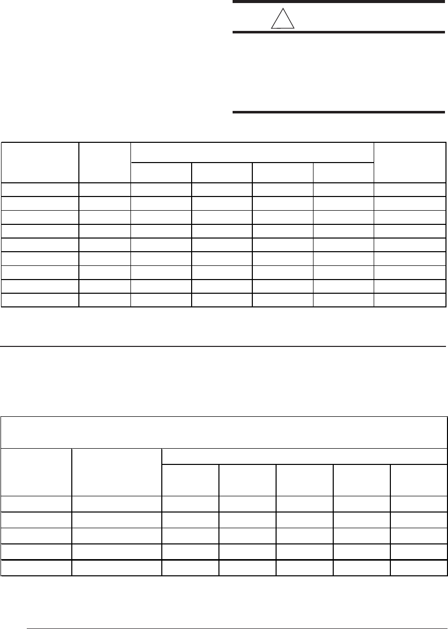
Table 3. Furnace Dimensions and Shipping Weights
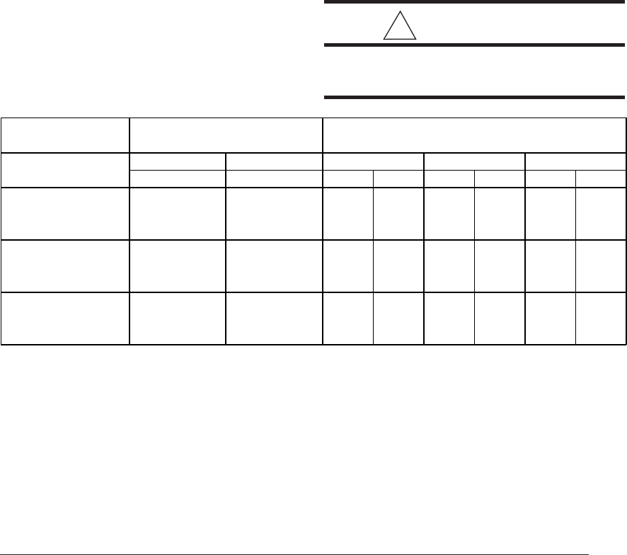
Table 4. Minimum Clearances to Combustible Materials
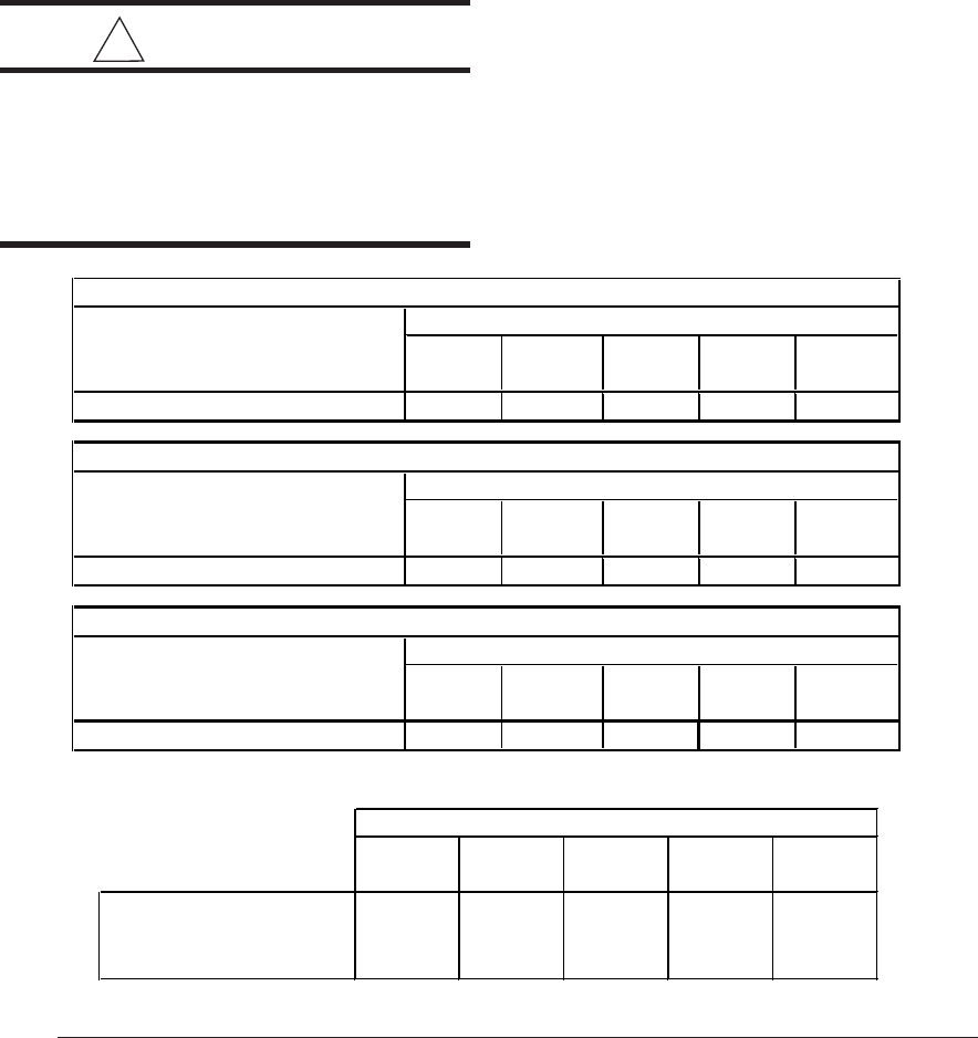
* 24 inches is the minimum clearance for servicing.
36 inches is the recommended clearance for service.
CLEARANCES TO COMBUSTIBLE MATERIALS
This furnace is Designed Certified by AGA/CGA Laboratories for the minimum clearances to
combustible material listed in Table 4. See the furnace name plate, located inside the furnace
cabinet, for specific model number and clearance information.
MINIMUM CLEARANCES TO COMBUSTIBLE MATERIAL
Furnace Cabinet Minimum Clearances (Inches)
Input Width
(Btuh) (Inches) Side Vent Back Top Front
40,000 14 1/4 0 0 0 1 1*
60,000 14 1/4 0 0 0 1 1*
80,000 14 1/4 0 0 0 1 1*
100,000 19 3/4 0 0 0 1 1*
120,000 22 1/2 0 0 0 1 1*
INSTALLATION REQUIREMENTS
Requirements and Codes
This furnace must be installed in accordance
with these instructions, all applicable local build-
ing codes, and the current revision of the Na-
tional Fuel Gas Code (ANSI-Z223.1, NFPA-54).
The current revision of the National Fuel Gas
Code is available from:
American National Standards Institute, Inc.
1430 Broadway
New York, New York 10018
Canada installations shall comply with CAN/
CGA-B149 installation codes, local plumbing or
waste water codes and other applicable codes.
Additional helpful publications are:
• NFPA-90A - Installation of Air Conditioning
and Ventilating Systems.
• NFPA-90B - Warm Air Heating and Air
Conditioning Systems.
These publications are available from:
National Fire Protection Association, Inc.
Batterymarch Park
Quincy, Massachusetts 02269
! WARNING:
This furnace is not approved for in-
stallation in mobile homes. Installa-
tion in a mobile home could cause
fire, property damage, and/or personal
injury.
G6R(C,D)040C 40,000 14 1/4 12 3/4 5 1/8 11 3/4 133
G6R(C,D)060C 60,000 14 1/4 12 3/4 5 1/8 11 3/4 140
G6R(C,D)080C 80,000 19 3/4 18 1/4 7 7/8 17 1/4 172
G6R(C,D)100C 100,000 19 3/4 18 1/4 7 7/8 17 1/4 180
G6R(C,D)120C 120,000 22 1/2 21 9 1/4 20 204
G6RL040C 40,000 14 1/4 12 3/4 4 5/8 12 3/4 135
G6RL060C 60,000 14 1/4 12 3/4 4 5/8 12 3/4 135
G6RL080C 80,000 19 3/4 18 1/4 10 18 1/4 174
G6RL100C 100,000 19 3/4 18 1/4 10 18 1/4 185
AB
Dimensions (inches)
Furnace
Btuh CD
Shipping
Weight
(
lbs
)
Model
Number
9
Location
The furnace must be installed on a level surface,
and as close to the center of the air distribution
system as possible. See Table 3 for overall
dimensions to determine the required clear-
ances in hallways, doorways, stairs, etc. to allow
the furnace to be moved to the installation point.
The furnace must be installed so that all electri-
cal components are protected from water.
Minimum clearances to combustible materials
are listed in Table 4. Access for positioning and
servicing must be considered when locating the
unit. 24 inches is the minimum required clear-
ance for servicing the unit. 30 inches is the
minimum required clearance for positioning the
unit. 36 inches is the recommended clearance
from the front of the unit. Please note that a
panel or door can be located such that the
minimum clearance on the rating plate is satis-
fied, but that panel or door must be removable
and allow the appropriate clearance for your
installation.
This furnace is certified for use on wood flooring.
The furnace must be installed on a solid surface
and must be level front to back and side to side.
This furnace must not be installed directly on
carpeting, tile, or any combustible material other
than wood flooring.
DOWNFLOW WARNING
(G6RL Models):
The design of the downflow furnace is certified
for natural or propane gas and for installation on
non-combustible flooring. A special combus-
tible floor sub-base is required when installing
on a combustible floor. Failure to install the sub-
base may result in fire, property damage and
personal injury. The special downflow sub-bases
are factory supplied accessories, part numbers
902677 and 902974. When the furnace is in-
stalled on a factory or site-built cased air condi-
tioning coil, the sub-base is not necessary.
However, the plenum attached to the coil casing
must be installed such that its surfaces are at
least 1" from combustible construction.
A gas-fired furnace installed in a residential
garage must be installed so that the bottom of
the furnace is located a minimum of 15" from the
floor. The furnace must be located or protected
to avoid physical damage by vehicles.
HORIZONTAL INSTALLATIONS
The G6RC model furnaces are approved for
horizontal installation. Installation Kit #903568
is required for horizontal applications. Follow
the installation instructions in the kit for proper
conversion. NOTE: The G6RD and G6RL mod-
els are NOT approved for horizontal installation.
SUPPLY AIR PLENUM INSTALLATION
A. Installation on a concrete slab - G6RL
1. Construct a hole in the floor per the
dimensions in Figure 3.
2. Place the plenum and the furnace as
shown in Figure 4.
B. Installation on a combustible floor - G6RL
1. Cut and frame the hole in the floor per
the dimensions in Figure 5.
2. Place the sub-base for combustible floors
over the hole with its duct collar extended
downward. Attach the supply air plenum to
the base in a manner which will ensure 1"
clearance to the flooring or other combustible
material. Place furnace on the combustible
base as shown in Figure 6.
3. When the furnace is installed on a factory
or site-built cased air conditioning coil,
the sub-base is not necessary. However,
the plenum attached to the coil casing
must be installed such that its surfaces
are at least 1" from combustible material.
Hole in
Floor
19.25"
18.75"
Hole in
Floor
19.25"
13.25"
G6RL 080/100 G6RL 040/060
Figure 3. Opening for Concrete Slab
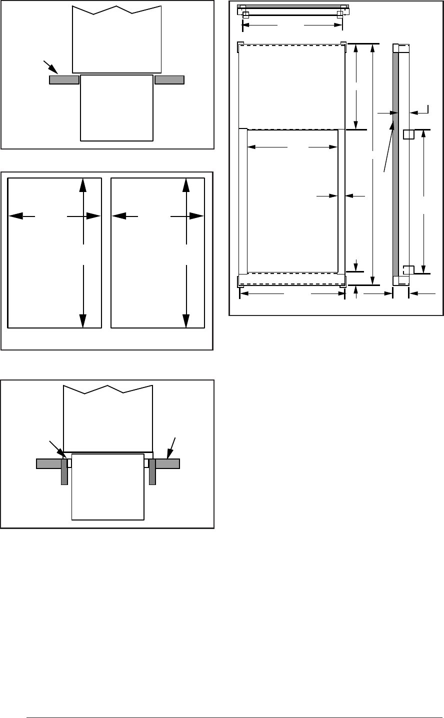
10
19.63"
18.75"
19.63"
13.25"
Hole in
Floor Hole in
Floor
Downflow Wood
Sub-base Floor
Furnace
Sheet
Metal
Plenum
Figure 5. Opening in Wood Floor
G6RL 080/100 G6RL 040/060
Figure 6. Furnace on a Wood Floor
1 inch thick fiberglass 3 lb density
28.38"
9.25"
19.63"
3"
19.75"
or 14.25"*
2.0"
1.58"
1.50"
16.75"
or 11.25"*
18.75"
or 13.25"*
Concrete
Floor Furnace
Sheet
Metal
Plenum
Figure 4. Furnace on a Concrete Slab
CIRCULATING AIR SUPPLY
Plenums and air ducts must be installed in
accordance with the Standard for the Installa-
tion of Air Conditioning and Ventilating Systems
(NFPA No. 90A) or the Standard for the Installa-
tion of Warm Air Heating and Air Conditioning
Systems (NFPA No. 90B).
* Smaller
dimensions for
G6RL 040/060
Figure 7. Downflow Sub-Base Dimensions
If outside air is utilized as return air to the furnace
for ventilation or to improve indoor air quality, the
system must be designed so that the return air to
the furnace is not less than 50°F (10°C) during
heating operation. If a combination of indoor and
outdoor air is used, the ducts and damper system
must be designed so that the return air supply to
the furnace is equal to the return air supply under
normal, indoor return air applications.
When a cooling system is installed which uses
the furnace blower to provide airflow over the
indoor coil, the coil must be installed down-
stream (on the outlet side) or in parallel with the
furnace.
If a cooling system is installed in parallel with the
furnace, a damper must be installed to prevent
chilled air from entering the furnace and con-
densing on the heat exchanger. If a manually
operated damper is installed, it must be de-
signed so that operation of the furnace is pre-
vented when the damper is in the cooling posi-
tion and operation of the cooling system is
prevented when the damper is in the heating
position.
11
! WARNING:
Products of combustion must not be
allowed to enter the return air ductwork
or the circulating air supply. Failure to
prevent products of combustion from
being circulated into the living space
can create potentially hazardous con-
ditions including carbon monoxide
poisoning that could result in per-
sonal injury or death.
All return ductwork must be ad-
equately sealed, all joints must be
taped, and the ductwork must be
secured to the furnace with sheet metal
screws. When return air is provided
through the bottom of the furnace, the
joint between the furnace and the re-
turn air plenum must be sealed.
The floor or platform on which the
furnace is mounted must provide
sound physical support of the furnace
with no gaps, cracks, or sagging be-
tween the furnace and the floor or
platform.
Return air and circulating air ductwork
must not be connected to any other
heat producing device such as a fire-
place insert, stove, etc.
Return Air
The return air ductwork may be connected to
any or all of the following: left side return, right
side return, or bottom return. Tables 1 and 2
show the airflow data for each furnace model.
Where maximum airflow is 1800 CFM or
more two openings must be used.
VENTING AND COMBUSTION AIR
REQUIREMENTS
NORDYNE condensing furnaces may be in-
stalled with outdoor combustion air piped di-
rectly to the furnace, or without such special
piping. Codes refer to the former as "direct vent"
or "two pipe" installation. Installation with air
taken from around the furnace is sometimes
referred to as "one pipe" installation - i.e. only
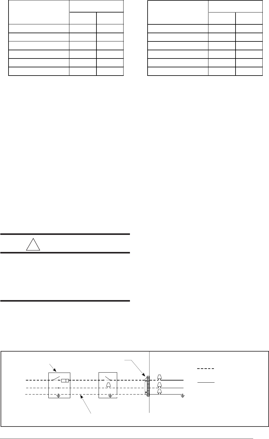
the vent (exhaust) pipe is provided. Figure 8. Protective Screen for One Pipe
Installations
Protective Screen
G6RC/G6RD
G6RL
An important consideration in selecting one or
two pipe installation is the quality of the combus-
tion air. Indoor air is sometimes contaminated
with various household chemicals which can
cause severe corrosion in the furnace combus-
tion system. Some common sources of these
chemicals are detergents, bleaches, aerosol
sprays, and cleaning solvents. Unless indoor air
is known to be free of these materials, two pipe
installation is recommended.
Provisions must be made for adequate supply of
air for combustion and ventilation. For United
States installations, the adequacy of air provi-
sions can be determined by consulting the cur-
rent version of the National Fuel Gas Code
(ANSI Z223.1/NPFA-54). For Canadian installa-
tions, requirements are specified in the National
Standard of Canada (CAN/CGA B149.1 & .2).
Consult local codes for special requirements.
NOTE: If the furnace is operated without ad-
equate air for combustion and ventilation, it may
not perform properly. Furnace components may
be strained by high temperature and could fail
prematurely.
! WARNING:
Furnace installation using methods
other than those described in the fol-
lowing sections must comply with the
National Fuel Gas Code and all appli-
cable local codes to provide sufficient
combustion air for the furnace.
12
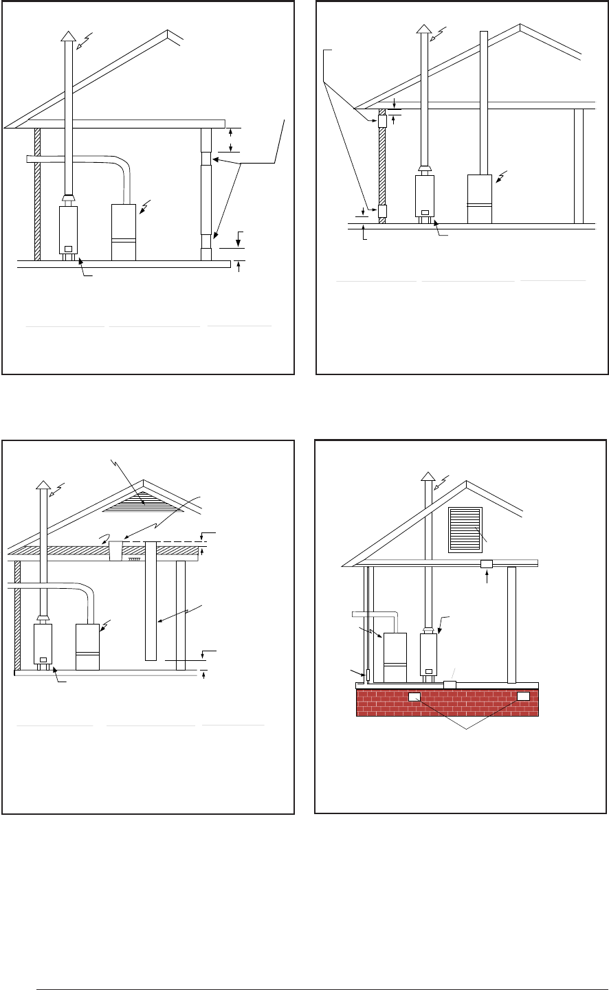
Each opening
to outside must
be at least
1 sq. in. per
4000 Btuh of
total input
rating.
12" Max
Total Input
Rating (Btuh)
40,000
60,000
80,000
100,000
120,000
140,000
160,000
Minimum
Free Area
(Each Opening)
10 sq. in.
15 sq. in.
20 sq. in.
25 sq. in.
30 sq. in.
35 sq. in.
40 sq. in.
Round Duct
Diameter
4"
5"
5"
6"
6"
7"
8"
-
-
-
-
-
-
-
-
-
-
-
-
-
-
-
-
-
-
Furnace
Water Heater
Vent or
Chimney
12"
Max
Figure 11. Equipment in a Confined Space
with all Combustion Air drawn from
Outdoors through Vertical Ducts – from
Ventilated Attic
Air Duct must be
at least 1 sq. in.
per 4,000 Btuh of
total input rating.
Ducts must
extend above
attic insulation.
Air Duct must be
at least 1 sq. in.
per 4,000 Btuh of
total input rating.
Ventilation Louvers at each end of attic
Attic
Insulation
12" Max
Total Input
Rating (Btuh)
40,000
60,000
80,000
100,000
120,000
140,000
160,000
Minimum
Free Area
(Each Opening)
10 sq. in.
15 sq. in.
20 sq. in.
25 sq. in.
30 sq. in.
35 sq. in.
40 sq. in.
Round Duct
Diameter
4"
5"
5"
6"
6"
7"
8"
Furnace
Water Heater
Vent or
Chimney
Figure 10. Equipment in a Confined Space
with all Combustion Air drawn from
Outdoors through Exterior Wall
Water
Heater
Vent or
Chimney
-
-
-
-
-
-
-
-
-
-
-
-
-
-
-
-
-
-
Furnace
Ventilation Louvers For
Unheated Crawl Space
-
-
-
-
-
-
-
-
-
Inlet Air
Ventilation Louvers
(each end of attic)
NOTE: Air open-
ings shall each
have a free area
of not less than
one square inch
per 4,000 Btuh of
the total input rat-
ing of all equipment
in the enclosure.
-
-
-
-
-
-
-
-
-
Alternate
Air Inlet
Outlet
Air
Total Input
Rating (Btuh)
40,000
60,000
80,000
Round Duct
Diameter
12"
12"
12"
Minimum
Free Area
(Each Opening)
100 sq. in.
100 sq. in.
1
00
sq
. in.
Furnace
12" Max.
12" Max.
Water Heater
Vent or
Chimney Each opening must
be at least 100 sq. in.
or 1 sq. in. per 1000
Btuh of total input
rating, whichever is
greater. See minimum
area per table.
Figure 9. Equipment in a Confined Space
with all Combustion Air drawn from Inside
Figure 12. Equipment in a Confined Space
with all Combustion Air drawn from
Outdoors through Ventilated Crawl Space
and Ventilated Attic
13
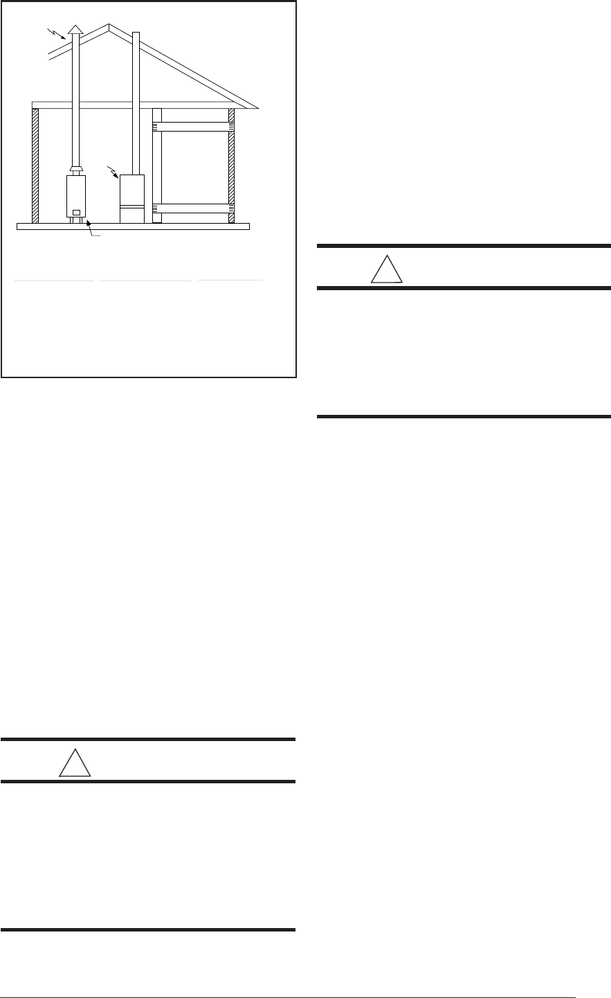
Total Input
Rating (Btuh)
40,000
60,000
80,000
100,000
120,000
140,000
160,000
Minimum
Free Area
(Each Opening)
20 sq. in.
30 sq. in.
40 sq. in.
50 sq. in.
60 sq. in.
70 sq. in.
80 sq. in.
Round Duct
Diameter
5"
6"
7"
8"
9"
10"
10"
Furnace
Water Heater
Air Duct
must be
at least
1 sq. in.
per 2000
Btuh of
total input
rating.
Vent or
Chimney
Air Duct
Air Duct
Figure 13. Equipment in a Confined Space
with all Combustion Air Drawn from the
Outside through Horizontal Ducts
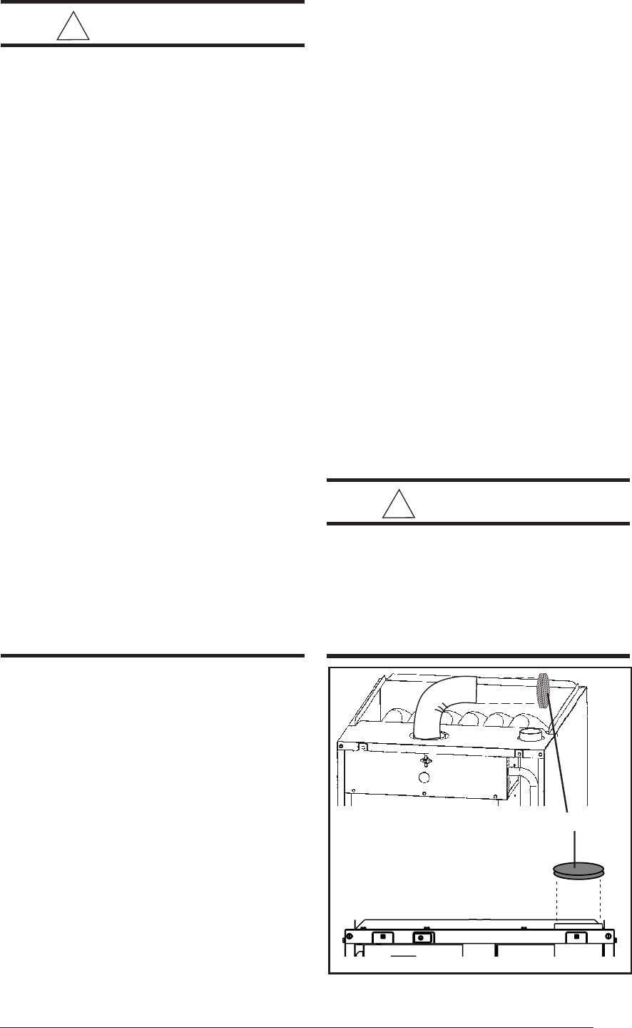
Air Requirements For One-Pipe
Installation
When air for combustion is to be taken from
around the furnace, a protective screen must be
installed over the combustion air intake open-
ing. This screen is provided with the furnace
installation instructions and functions to prevent
debris from entering the combustion system. It
should be installed on the combustion air intake
collar or inlet PVC. If furnace location is such
that this opening might be unintentionally ob-
structed, a 3" PVC elbow should be installed on
the collar, and the screen placed inside the inlet
of the elbow. See Figure 8.
Installation In An Unconfined Space
! CAUTION:
"Tight" buildings (with weather strip-
ping and caulk to reduce infiltration),
may require special provisions for in-
troduction of outside air to ensure
satisfactory combustion and venting,
even though the furnace is located in
an unconfined space.
An unconfined space is an area including all
rooms not separated by doors with a volume
greater than 50 cubic feet per 1,000 Btuh of the
combined input rates of all appliances which draw
combustion air from that space. For example, a
space including a water heater rated at 45,000
Btuh and a furnace rated at 75,000 Btuh requires
a volume of 6,000 cubic feet [50 x (45 + 75) =
6,000] to be considered unconfined. If the space
has an 8 foot ceiling, the floor area of the space
must be 750 square feet (6,000 / 8 = 750). In
general, a furnace installed in an unconfined
space will not require outside air for combustion.
! WARNING:
Furnaces installed with combustion
air drawn from a heated space which
includes exhaust fans, fireplaces, or
other devices that may produce a
negative pressure should be consid-
ered confined space installations.
Installation In A Confined Space
A confined space is one which does not meet the
unconfined space volume requirements, and
typically involves installation in a small room. All
such installations must have specific provisions
for introduction of combustion and ventilation
air.
Codes require that two openings be pro-
vided for this - one with bottom edge within 12"
of the floor and one with top edge within 12" of
the ceiling.
The size and other criteria for these
openings must be per the following sections.
Combustion air openings must not be restricted
in any manner.
Furnaces installed in a confined space which
supply circulating air to areas outside of the
space must draw return air from outside the
space and must have return air ducts tightly
sealed to the furnace.
Air From Inside
Air for combustion and ventilation may be taken
from inside the building through an interior wall
if the building is not "tight" and if the total volume
of the furnace space and the space from which
air is drawn meets the volume requirements for
an unconfined space.
In such cases, the two
openings in the wall must each have free area of
at least one square inch per 1000 Btuh of
total
appliance input, but not less than 100 square
14
inches of free area. See Figure 9. For example,
if the combined input rate of all appliances is less
than or equal to 100,000 Btuh,
each
opening
must have a free area of at least 100 square
inches. If the combined input rate of all appli-
ances is 120,000 Btuh,
each
opening must have
a free area of at least 120 square inches.
Air Directly Through An Exterior Wall
If combustion air is provided directly through an
exterior wall, the two openings must
each
have
free area of at least one square inch per 4000
Btuh of
total
appliance input. (See Figure 10.)
Outdoor Air Through Vertical Openings or Ducts
If combustion air is provided through vertical
ducts or openings to attics or crawl spaces, the
two openings must each have free area of at
least one square inch per 4000 Btuh of total
appliance input. Ducts must have cross-sec-
tional areas at least as large as the free area of
their respective openings to the furnace space.
Attics or crawl spaces must communicate freely
with the outdoors if they are the source of air for
combustion and ventilation. (See Figures 11
and 12.)
Outdoor Air Through Horizontal
Openings or Ducts
If combustion air is taken from outdoors through
horizontal ducts, the openings must
each
have
free area of at least one square inch per 2000
Btuh of total appliance input. Ducts must have
cross-sectional area at least as large as the free
area of their respective openings to the furnace
space. (See Figure 13.)
! CAUTION:
Do not supply combustion air from an
attic space that is equipped with power
ventilation or any other device that
may produce a negative pressure.
VENTING REQUIREMENTS
This section specifies installation requirements
for vent and "2-pipe" combustion air piping. For
"one pipe" installations, install vent piping per
this section and provide air for combustion and
ventilation per the previous section. The capac-
ity table provided in this section applies to the
total of vent and combustion air piping for either
type of installation.
NORDYNE condensing furnaces are classified
as "Category IV" appliances, which require spe-
cial venting materials and installation proce-
dures. Category IV appliances operate with
positive vent pressure and therefore require
vent systems which are thoroughly sealed. They
also produce combustion condensate, which is
slightly acidic and can cause severe corrosion of
ordinary venting materials. Furnace operation
can be adversely affected by restrictive vent and
combustion air piping. Therefore,
vent and com-
bustion air piping lengths must conform com-
pletely to the requirements of Table 5.
The furnace must be vented to the outdoors. It
must not be vented in common with any other
appliance, even if that appliance is of the con-
densing type. Common venting can result in
severe corrosion of other appliances or their
venting and can allow combustion gases to
escape through such appliances or vents. Do
not vent the furnace to a fireplace chimney or
building chase.
! WARNING:
FURNACE MUST NOT BE COMMON
VENTED WITH OTHER APPLIANCES.
Vent Pipe Material
Vent and combustion air pipe and fittings must
be one of the following materials and must
conform to the indicated ANSI/ASTM standards:
Material Standard
Schedule 40 PVC D1785
PVC-DWV D2665
SDR-21* D2241
& SDR-26*
ABS-DWV D2661
Schedule 40 ABS F628
Cement and primer must conform to ATSM
Standard D2564 for PVC and Standard D2235
for ABS. When joining PVC piping to ABS, use
PVC solvent cement. (See procedure specified
in ASTM Standard D3138.)
Vent Pipe Length and Diameter
In order for the furnace to operate properly, the
combustion air and vent piping must not be exces-
sively restrictive. To ensure this use Table 5, which
indicates the maximum allowable piping length for
a furnace of specified input rate, when installed
15
with piping of selected diameter and number of
elbows. This table applies to the length and num-
ber of elbows for each pipe. To use the table, the
furnace input rate, the centerline length and the
number of elbows on each pipe must be known.
Choose the diameter for which the tabulated length
is equal to or greater than required.
Proper use of the table is illustrated by the
following example:
Example:
An 80,000 Btuh furnace is to be installed in a
"one-pipe" system with 40 feet of vent piping.
There are four elbows, including those exterior
to the building.
Solution:
Consulting Table 5, in the single pipe length
column for an 80,000 Btuh furnace, the maxi-
mum allowable length of 2" is 60 feet with one
elbow. Select 2-1/2 or 3" pipe. For three addi-
tional elbows, deduct 2.5 ft. for each elbow, or
7.5 ft. for a maximum installed vent length of
52.5 ft.
Condensing furnace combustion products have
very little buoyancy, so Table 5 is to be used
without consideration of any vertical rise in the
piping.
NOTE: Always use the same or larger size
piping for combustion air as is used for the
exhaust vent.
Vent Pipe Installation
Pipe Routing and Support
Route piping as directly as possible between the
furnace and the outdoors and remember that
routing affects pipe size requirements per the
preceding section. If a two pipe system is used,
locate the combustion air intake and the vent
exhaust in the same atmospheric pressure zone
- i.e. both must exit the building though the same
portion of exterior wall or roof. Vent piping must
be sloped upwards not less than 1/4" per foot in
the direction from the furnace to the terminal.
This is to ensure that any condensate flows back
to the furnace (where it can be disposed of
through the condensate disposal system).
The quality of outdoor air must also be consid-
ered. Be sure that the combustion air intake is
not located near a source of solvent fumes or
other chemicals which can cause corrosion of
the furnace combustion system.
!
CAUTION:
Combustion air must not be drawn
from a corrosive atmosphere.
*NOTES
1. Subtract 2.5 ft. for each additional 2" elbow and 3.5 ft. for each additional 3" elbow.
2. Two 45 degree elbows are equivalent to one 90 degree elbow.
3. One short radius elbow is equivalent to two long radius elbows
4. Do not include termination elbows in calculation of vent length
5. This table is applicable for elevations from sea level to 2000 ft. For higher elevations decrease
vent pipe lengths by 8% per 1000 ft. of altitude.
6. Only the above pipe materials are approved for use with G6 Condensing Furnaces.
Table 5. Vent Table
APPLICATION SINGLE PIPE LENGTH (ft.) DIRECT VENT, DUAL PIPE LENGTH (ft.)
with 1 long radius elbows*. with 1 long radius elbows on each pipe.*
PVC,CPVC or ABS Outlet Outlet Inlet/Outlet Inlet/Outlet Inlet/Outlet
SCH. 40 Pipe Size 2" 3" 2" 2" 3" 2" 3" 3"
Models
G6RC,D,L 80 150 40 40 50 50 90 90
040
Models
G6RC,D,L 60 150 30 30 35 35 90 90
060 & 080
Models
G6RC,D,L 30 150 15 15 25 25 90 90
100 & 120
16
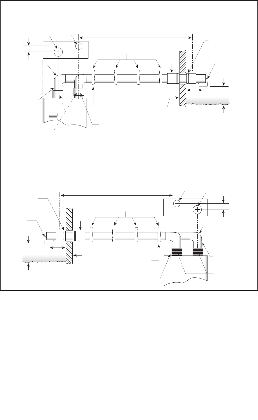
G6RL Downflow Furnaces
G6RC & G6RD Upflow Furnaces
5/8" Inlet Exhaust
Combustion
Offset with
Exhaust Pipe
for Adequate
Dimensional
Clearance
PVC or
ABS Pipe
See Vent Table 4
Straps or Other Suitable
Supports at Minimum of 5 ft. Intervals
Upward Pitch - 1/4" per Foot
Outlet Exhaust Vent
First Support Placed
as Close to Furnace
Connection as Possible
Exhaust Vent
Wall
Coupling
Seal/Caulk
around Pipe
at Building
90˚ Elbow
12" Min.
Normal Snow Level
7"
Straight Neoprene Coupling
with 2 Hose Clamps*
(Optional - Not Shown)
5/8"
Inlet
Exhaust
Combustion Air
Inlet
Offset with Exhaust
Pipe for Adequate
Dimensional
Clearance
PVC or
ABS Pipe
See Vent Table 4
Straps or Other Suitable
Supports at Minimum of 5 ft. Intervals
Upward Pitch - 1/4" per Foot
Outlet Exhaust Vent
First Support Placed
as Close to Furnace
Connection as Possible
Exhaust Vent
Wall
Coupling
Seal/Caulk
around Pipe
at Building
90˚ Elbow
12" Min.
Normal Snow Level Straight Neoprene
Coupling with
2 Hose Clamps
Figure 14. Horizontal Venting
* These couplings are field-supplied and can be used if the installation requires breakable
connections in the piping. Note that a maximum of two couplings per pipe are allowed.
17
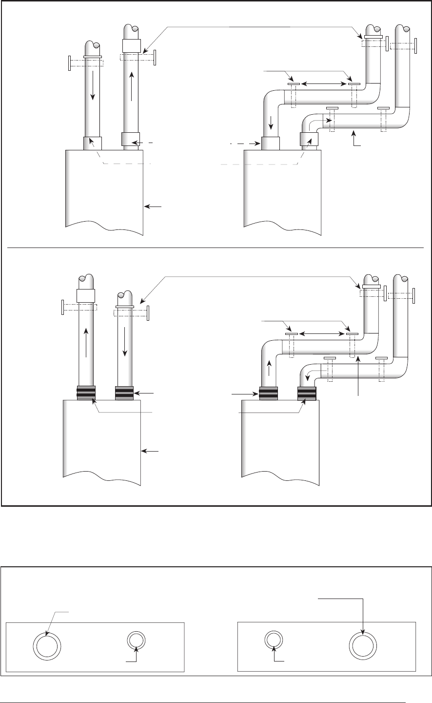
Combustion
Air Pipe
Exhaust
Vent
Cabinet
5'
Support System on
Vertical Rise Below Joints
Support System with
first support as close
to furnace as Possible
Upward Pitch
1/4" per Foot
Furnace Front
Straight Neoprene
Rubber Couplings
with 2 Hose Clamps
Combustion
Air Pipe Exhaust
Vent
Cabinet
5'
Support System on
Vertical Rise Below Joints
Support System with
first support as close
to furnace as Possible
Upward Pitch
1/4" per Foot
Furnace Front
Straight Neoprene
Couplings with
2 Hose Clamps*
(Optional - Not
Shown)
Combustion Air Inlet
2" PVC on G6RL 040/060 models,
3" PVC on G6RL 080/100 models
2" PVC
Exhaust Vent
All Models
Furnace Top
Combustion Air Inlet Pipe Collar
Diameter 3" for coupling or reducer
Furnace Top
2" PVC
Exhaust Vent
All Models
G6RL Downflow Furnaces
G6RC & G6RD Upflow
Furnaces
G6RL Downflow Furnaces
G6RC & G6RD Upflow
Furnaces
Figure 16. Furnace Pipe Adaptions
Figure 15. Vertical Venting
* These couplings are field-supplied and can be used if the installation requires breakable
connections in the piping. Note that a maximum of two couplings per pipe are allowed.
18
4 ft. min
12 in. min
12 in. min
12 in. min
9 in.
4 ft. min
12 in. min
12 in. min
Mechanical
draft vent
terminal
Direct vent
terminal
50,000 Btuh
or less
Forced
Air Inlet
Direct vent
terminal -
more than
50,000 Btuh
Mechanical
draft vent
terminal
Mechanical
draft vent
terminal
Grade
Less
than 10 ft.
3 ft. min.
Piping must be mechanically supported so that
its weight does not bear on the furnace. Sup-
ports must be at intervals no greater than five
feet, and at smaller intervals if necessary to
ensure that there are no sagging sections to trap
water. (See Figures 14 and 15.)
Figure 16 illustrates vent and combustion air
pipe sizes exiting the furnace. Transition to the
correct pipe size must be done close to the
furnace so that the full length of pipe is of proper
size.
Straight neoprene couplings are supplied with
the downflow furnaces only. These couplings
are to be installed in the combustion air inlet (if
present) and exhaust vent piping at the furnace
as shown in Figures 13 and 14. For an upflow
furnace installation, if breakable connections
are required in the combustion air inlet (if present)
and exhaust vent piping, then straight neoprene
couplings for 2” or 3” piping with hose clamps
can be used. These couplings can be ordered
through your local furnace distributor.
To install a coupling, slide the rubber coupling
over the end of the pipe that is attached to the
furnace and secure it with one of the hose
clamps. Then slide the other end of the rubber
coupling onto the other pipe from the vent and
secure the coupling with the second hose clamp.
Ensure that the connection is tight and leak free.
NORDYNE condensing furnaces have been
certified for installation with zero clearance be-
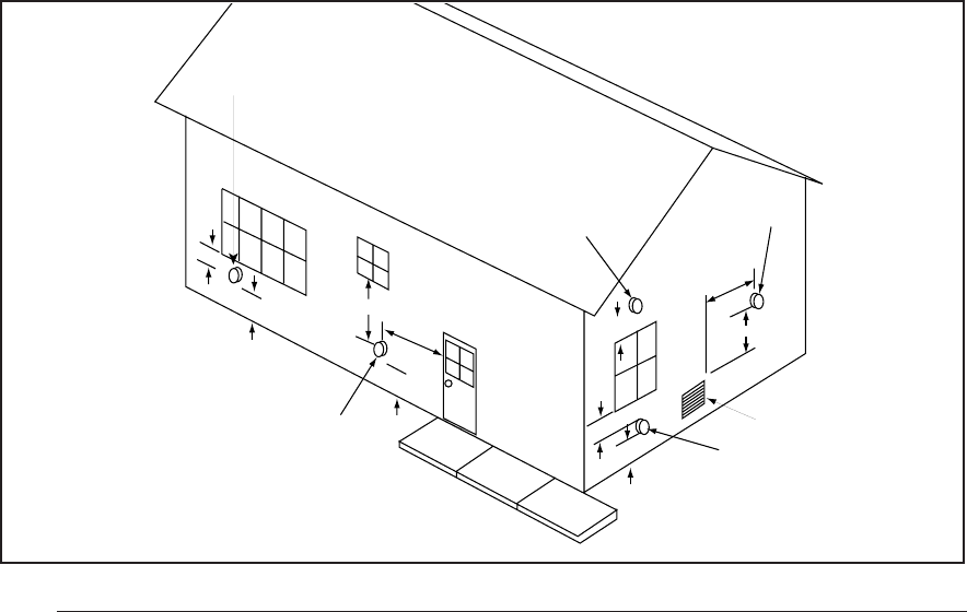
Figure 17. Vent Termination Clearances
tween vent piping and combustible surfaces.
However, it is good practice to allow space for
convenience in installation and service.
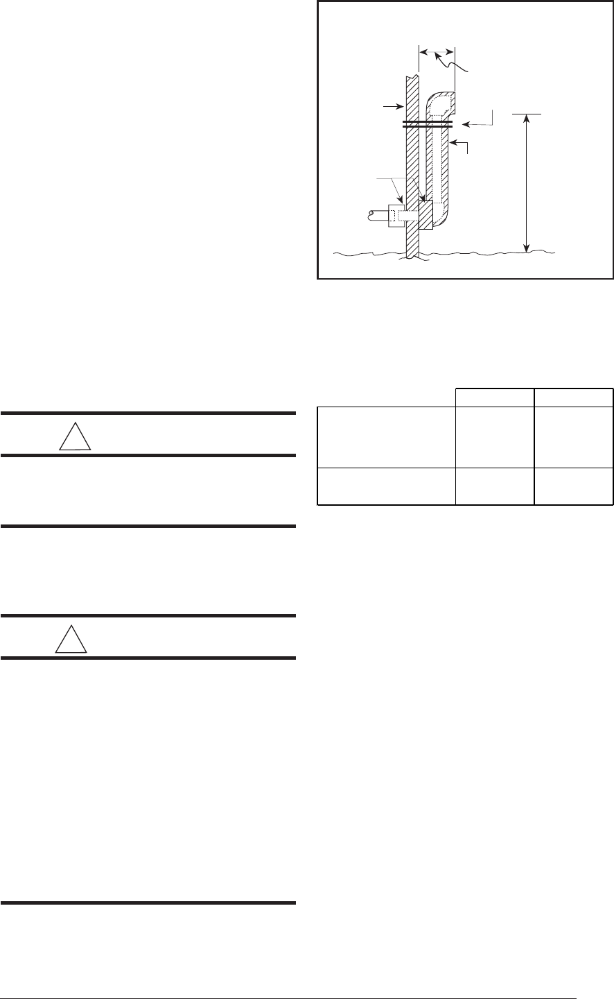
Location of Outdoor Terminations
Vent and combustion air intake terminations
must be located to ensure proper furnace opera-
tion and to conform to applicable codes. Figure
16 illustrates necessary distances from the vent
termination to windows and building air intakes.
In Canada, the Canadian Fuel Gas Code
takes precedence over these instructions.
Specifically, all minimum distance require-
ments with respect to termination of the vent
piping listed below (items 1 through 8).
The following list is a summary of vent terminal
location requirements:
1. The termination must be 12 inches above
snow level or grade level whichever is higher.
See Figure 18 for alternate method to
achieve 12" above snow level.
2. The minimum distance for a (1-pipe instal-
lation) from any door, (openable) window,
or gravity air inlet is 4 ft. below, 4 ft. horizon-
tally, or 1 ft. above.
3. The minimum distance for a direct vent (2-
pipe) installation) from any door, (openable)
window, or air gravity inlet is 1 ft. below, 1 ft.
horizontally, or 1 ft. above.
4. For one-pipe installations the recommended
minimum distance from an inside corner
formed by two exterior walls is 6 feet, but is
not required.
19
5. The vent termination for a 1-pipe installa-
tion shall be a minimum of 3 ft. above any
forced air inlet within 10 ft.
6. The vent termination shall be located at
least 4 ft. horizontally from any electric
meter, gas meter, regulator and any relief
equipment. These distances apply ONLY to
U.S. installations. In Canada, the Canadian
Fuel Gas Code takes precedence.
7. Avoid areas where condensate drainage
may cause problems by dropping on plant-
ers or patios, etc. Also ensure that exhaust
gases will not impinge on windows or build-
ing surfaces, which may be compromised
or damaged by condensation. Do not install
the vent terminal such that exhaust is di-
rected into window wells, stairwells, under
decks or into alcoves or similar recessed
areas, and do not terminate above any
public walkways.
8. Select the point of wall penetration where
the minimum 1/4 inch per foot of slope up
can be maintained.
! CAUTION:
For optimum performance, vent fur-
nace through wall which experiences
the least exposure to winter winds.
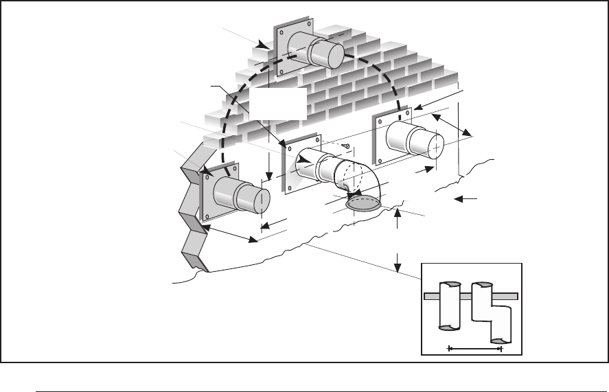
Horizontal Venting
Vent and combustion air intake terminations
must be as shown in Figure 19.
! WARNING:
Ensure that the combustion air vent
and the exhaust vent are configured as
shown in Figure 19. Improper vent
termination can cause recirculation of
the flue gases. This may result in fur-
nace vibration. In severe cases, the
furnace will cycle due to the intermit-
tent contact between the flame and the
flame sensor. If you note oscillations
occurring, check the vent configura-
tion. Make sure that the exhaust vent
does not have a 90 degree termination.
Figure 18. Alternate Horizontal Vent
Installation
Outside
Wall
Support
Pipe
Coupling
Vent Configuration to
Provide 12" Minimum
height above
Snow Level.
1/2"
Armaflex
Insulation or
Equivalent
12" Above
Normally
Expected
Snow
Level
12" Min.
19" Max.
For horizontal venting, one of the following kits
is recommended:
2" PVC 3" PVC
Through-the-Wall
Exterior Vent
Mountin
g
Kit
9023730 9023750
Neutralizer Kit - All
Models 9023730 9023730
For Canadian installations please refer to the
Canadian Installation Code (CAN/CGA-B149.1
or 2) and/or local codes.
The kit consists of two face plates and an
insulating gasket to seal the exterior surface. A
hole sized closely to the pipe diameter must first
be cut through the wall. A short length of pipe is
then cut such that it can penetrate the wall and
be held in place by closely fitting standard cou-
plings. The face plates are retained on both
sides of the wall by the couplings, and the gasket
is retained against the wall by the outer face
plate. Face plates must be fastened to the wall
and the outside one must be flashed as appro-
priate to prevent entry of water.
When the above kits are not used the following
steps are required:
1. Check the hole size cut through the exterior
wall. Insure that the hole diameter is less than
the diameter of the couplings to be used.
2. Extend the vent pipe through the wall ap-
proximately 1" and seal the area between
the wall and pipe.
20
3. Apply couplings to the vent pipe on the
interior and exterior sides of the wall to
insure the pipe can not be pushed or pulled
through the wall.
4. Insure the combustion air inlet pipe (for a 2
pipe installation) has a 90 degree termina-
tion elbow as shown in Figures 19 and 20.
Note that a combustion air intake must be
provided with an elbow opening downward.
The screen provided with the furnace must be
installed in the elbow to prevent entry of debris
or creatures.
When the vent pipe must exit an exterior wall
close to the grade or expected snow level, a riser
should be provided as shown in Figure 18.
Insulation is required to prevent freezing of this
section of pipe.
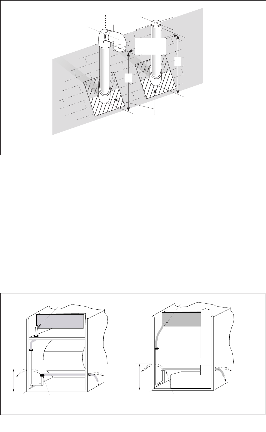
Vertical Venting
Figure 20 shows the proper installation and clear-
ances for vertical vent termination. The roof penetra-
tion must be properly flashed and waterproofed with
a plumbing roof boot or equivalent flashing. Termi-
nation spacing requirements from the roof and from
each other must be per Figure 20.
Vent and combustion air piping may be installed
in an existing chimney which is not in use
provided that:
a. Both the exhaust vent and air intake run
the length of the chimney.
b. The top of the chimney is sealed and
weatherproofed.
c. The termination clearances shown in
Figure 20 are maintained.
d. No other gas fired appliances are vented
through the chimney.
Vent Freezing Protection
When the vent pipe is exposed to temperatures
below freezing, i.e., when it passes through
unheated spaces, chimneys, etc., the pipe must
be insulated with 1/2 inch thick sponge rubber
insulation, Armaflex-type insulation or equiva-
lent. Insulating pipe is important to avoid con-
densate icing.
For extremely cold climates or for conditions of
short furnace cycles (i.e. set back thermostat
conditions) the last three feet of vent pipe can be
reduced one nominal pipe size provided that the
total vent length is at least 15 feet in length and
the vent is sized in accordance with the venting
requirements (Table 5) before this reduction is
applied. (Example: 3" to 2-1/2" or 2" to 1-1/2")
Smaller vent pipes are less susceptible to freez-
ing, but must not be excessively restrictive.
Concentric Vent Termination
A concentric vent termination is approved for
use with these furnaces. The kit part number is
903578. For proper installation of the concentric
vent termination, follow the installation instruc-
tions provided with that kit.
36" max.
18" min.
Exhaust Vent
Option B
Exhaust Vent
Option A
Exhaust Vent
Option C
Mounting Kit
Faceplate Secured
to Wall with Screws
18" Min.
36" Max.
7" Min.
8" Min.
12" Min. to
Normal Snow Level
Combustion
Air Inlet
Grade
Level
or Normal
Snow
Inlet Exhaust
18" Min.
36" Max.
Figure 19. Exhaust and Combustion Air Pipe Clearances
21
Combustion
Air
Intake
Elbow
Exhaust
Vent
Exhaust
Plumbing Vent Roof Boot
(Typ. Both Pipes)
A
1"
18" Min.
36" Max.
A
Figure 20. Vertical Vent Termination
A= 12" Above Roof or Snow Accumulation Level
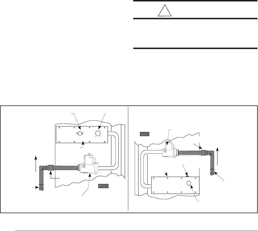
DRAINAGE OF CONDENSATE
FROM FURNACE
The condensate drainage system is internal to
the furnace. The drain may exit either the right or
left side of the furnace cabinet. For a right side
drain simply extend the tubing out of the 7/8"
hole in the cabinet, see Figure 21.
For a left side drain follow the steps below:
1. Loosen the clamp on the soft exit tube (see
Figure 21.)
2. Rotate the soft exit tube (counter clockwise,
180° upflow G6RC/RD models; clockwise
90° downflow G6RL models.)
8"
Left Side
Drain
"HARD" J
Drain Tube
Clamp
(Loosen For Step 1)
(Retighten for Step 3)
Route to
floor drain.
...OR
Route to
condensate
pump. Keep
downward
slope.
Collector Box
A
Rotate counter
clockwise (Step 2)
8"
Left
Side
Drain
"HARD" J
Drain Tube
Clamp
(Loosen For Step 1)
(Retighten for Step 3)
Route to
floor drain.
...OR
Route to
condensate
pump. Keep
downward
slope.
Collector Box
A
Rotate clockwise
(Step 2)
G6RLG6RC & G6RD
3. Re-tighten the clamp. MAKE SURE CLAMP
IS TIGHT TO AVOID LEAKAGE OF CON-
DENSATE.
4. Route the tubing out of the 7/8" hole located
8 inches up from the bottom furnace.
The condensate should drain from the plastic
collector box (location A in Figure 21) as droplets
or a small stream. If you notice the furnace has
operated for more than 5 minutes without drain-
ing or the red status light on the control board is
pulsing a 2-blink code follow the steps below.
1. Remove the collector box soft tube at loca-
tion A in Figure 21 and insure the exit from
Figure 21. Furnace with Condensate Drain Trap Assembly
22
Leak Check
After the gas piping to the furnace is complete,
all connections must be tested for gas leaks. To
check for leaks use only a soap and water
solution or other approved method.
Some Utilities
Require Shut-
Off Valve to
be 4 to 5 feet
Above Floor
Denotes field-
provided and
installed
components.
Shut-Off Valve
with 1/8" NPT
Plugged Tap
Burner Viewport
Roll-Out Limit
Automatic Gas Valve
(with manual shut-off)
Burner
Assembly
Ground
Joint
Union
the collector box is clear of any debris or
obstructions.
2. Replace this tube and insure the fit to the
header spout is air tight. Air will be drawn
into the header if this connection is not tight.
3. Check other tube connections along the
drain system. Insure that all are air tight.
NOTE: Industry research studies indicate that
when condensate is routed to an active drain,
household detergents, etc., buffer its acidity. If
the drain is not actively used or if codes require,
obtain a neutralizer kit (usually contains lime-
stone). Proper drains and connections to the
condensate tubing are required as NORDYNE
cannot be held responsible for water leakage
which occurs due to loose hose connections or
improperly sealed drain line pipes.
GAS SUPPLY AND PIPING
This furnace is equipped for either left or right
side gas entry. Typical gas service hook-ups are
shown in Figure 22. When making the gas
connection provide clearance between the gas
supply line and the entry hole in the furnace
casing to avoid unwanted noise and/or damage
to the furnace.
All gas piping must be installed in compliance
with local codes and utility regulations. Some
local regulations require the installation of a
manual main shut-off valve and ground joint
union external to the furnace. The shut-off valve
should be readily accessible for service and/or
emergency use. Consult the local utility or gas
supplier for additional requirements regarding
placement of the manual main gas shut-off. In
the absence of local codes the gas line installa-
Figure 22. Typical Gas Service Connection
Some Utilities
Require Shut-
Off Valve to
be 4 to 5 feet
Above Floor
Denotes field-
provided and
installed
components.
Shut-Off Valve
with 1/8" NPT
Plugged Tap
Burner Viewport
Automatic
Gas Valve
(with manual
shut-off)
Burner
Assembly
Ground Joint
Union
Roll-Out Limit
tion must comply with the latest edition of the
National Fuel Gas Code (ANSI Z223.1) or (CAN/
CGA B149) installation codes.
A 1/8" NPT plugged tap must be installed in the
gas line to the unit for use when measuring the
gas supply pressure. The plug should be readily
accessible for service use. A drip leg should be
installed in the vertical pipe run to the unit. Table
5 lists gas flow capacities for standard pipe sizes
as a function of length in typical applications
based on nominal pressure drop in the line.
NOTE: Gas piping must not be run in or
through air ducts, chimneys, gas vents, elevator
shafts, etc.
Compounds used on threaded joints of gas
piping must be resistant to the actions of lique-
fied petroleum gases.
The main manual gas valve and main power
disconnect to the furnace must be properly
labeled by the installer in case emergency shut-
down is required.
! CAUTION:
Do not use matches, lighters, candles,
or other sources of open flame to
check for gas leaks.
23
Table 6. Capacity of Black Iron Gas Pipe (cu. ft. per hour)
for Natural Gas (specific gravity = .60)
The cubic feet per hour listed in the table above must be greater than the cubic feet per hour of gas
flow required by the furnace. To determine the cubic feet per hour of gas flow required by the
furnace, divide the input rate of the furnace by the heating value of the gas:
Cubic Feet Per Hour Required = Input To Furnace (Btu/hr)
Heating Value of Gas (Btu/Cu. Ft.)
NOMINAL LENGTH OF PIPE RUN
BLACK IRON (feet)
PIPE DIAMETER
(in.) 1020304050607080
1/2 130 90 75 65 55 50 45 40
3/4 280 190 150 130 115 105 95 90
1 520 350 285 245 215 195 180 170
1 1/4 1050 730 590 500 440 400 370 350
1 1/2 1600 1100 890 760 670 610 560 530
CAPACITY OF BLACK IRON GAS PIPE (CU. FT. PER HOUR)
FOR NATURAL GAS
(
SPECIFIC GRAVITY - 0.60
)
NOTE: When pressure testing gas supply lines
at pressures greater than 1/2 psig (14 in. water
column), the furnace must be disconnected from
the gas supply piping system to prevent damage
to the gas control valve.
If the test pressure is less than or equal to 1/2
psig (14 in. water column), the furnace must be
isolated from the gas supply line by closing the
manual shut-off valve.
!
WARNING:
This furnace was equipped at the fac-
tory for use with natural gas only. A
special kit, supplied by the manufac-
turer, is required to convert the fur-
nace to operate on LP/propane gas.
Failure to use the proper conversion
kit can cause fire, explosion, property
damage, carbon monoxide poisoning,
personal injury, or death.
Conversion
Conversion of this furnace to use LP/propane
gas must be made by qualified service
personnel, using only approved parts.
High Altitude Application
High altitude application with this furnace can be
field performed by a simple adjustment of
manifold pressure, and if necessary changing
the orifices. The changes required depend on
the installation altitude and the heating value of
the gas. The gas heating value based on sea
level can be obtained from your local gas utility.
The heating value of gas at high altitude is
always lower than the sea level heating value.
The heating values used in Tables 7 & 8 are
based on sea level values.
Natural Gas High Altitude
Conversion
All factory shipped furnaces are ready to operate
between zero and 4999 ft. above sea level. For
higher altitudes (between 5000 and 10,000 ft.
above sea level), conversion can be achieved
simply by adjusting the furnace manifold pressure
as shown in Table 7.
LP/Propane Gas Sea Level and
High Altitude Conversion
Conversion of this furnace to utilize LP/propane
gas must be made by qualified service personnel,
using factory authorized or approved parts.
Conversion to LP/propane gas can be
accomplished by first replacing the natural gas
orifices with the appropriate LP/propane orifices
shown in Table 9 or 10. Note: for installations
between zero and 5000 ft. above sea level, a
#54 or #55 drill size orifice should be used
depending upon the rated firing rate of the unit
(see Table 9 or 10). However for installations
above 5000 ft. above sea level, a # 55 or #56 drill
size orifice should be used. After changing the
orifices, use Table 8 to determine the appropriate
manifold pressure for your installation.
24
Conversion to LP/propane, sea level, and high
altitude is detailed in the installation instructions
provided with the conversion kit. Approved
conversion kits are listed below.
United States LP/Propane Gas Sea Level and
High Altitude Conversion Kit - P/N 903616
This kit is for LP/propane conversion in the
United States at altitudes between zero and
10,000 ft. above sea level. Follow the installation
instructions supplied with the kit for proper
installation.
Canadian LP/Propane Gas Sea Level and High
Altitude Conversion Kit - P/N 903617
This kit is for LP/propane conversions in Canada
at altitudes between zero and 4500 ft. above sea
level. Follow the installation instructions supplied
with the kit for proper installation.
! CAUTION:
To avoid electric shock, personal in-
jury, or death, turn off the power at the
disconnect or the main service panel
before making any electrical connec-
tions.
ELECTRICAL WIRING
Electrical connections must be made in accor-
dance with all applicable local codes and ordi-
nances, and with the current revision of the
National Electric Code (ANSI/NFPA 70).
For Canadian installations electrical connec-
tions and grounding must be done in accor-
dance with the current Canadian Electrical Code
(CSA C22.1 Part 1) and/or local codes. If any of
the original wire as supplied with the furnace
must be replaced, it must be replaced with wire
having a minimum temperature rating of 105°C.
Refer to the furnace nameplate and Table 11 for
electrical requirements.
Line Voltage Wiring
The line voltage (115 volt) to the furnace must be
supplied from a dedicated branch circuit con-
taining the correct fuse or circuit breaker for the
furnace. See Table 11. An electrical switch
should be readily accessible from and within
sight of the furnace. (See the Wiring Diagram
label in the furnace and Figure 23.)
The furnace cabinet must have an uninterrupted,
unbroken ground to minimize injury should an
electrical fault condition occur. The controls
Table 7. Manifold Pressure (in WC) for Natural Gas at Various Altitudes
Table 8. Manifold Pressure (in WC) for LP/Propane Gas at Various Altitudes
Elevation (feet above sea level)
0 to 2,000 to 5,000 to 6,000 to 8,000 to
1,999 4,999 5,999 7,999 10,000
10.0 8.5 10.0 9.0 8.5
Manifold Pressure in (WC)
for an LP Gas Heating
Value of 2,500 Btu/hr.
For a Natural Gas Sea Level Heating Value of 800 to 899 Btu/cu.ft.
Elevation
(
feet above sea level
)
zero to
1999
2000 to
4999
5000 to
5999
6000 to
7999
8000 to
10000
Manifold Pressure Setting (in WC) 3.5 3.5 3.5 3.5 3.0
For a Natural Gas Sea Level Heating Value of 900 to 999 Btu/cu.ft.
Elevation
(
feet above sea level
)
zero to
1999
2000 to
4999
5000 to
5999
6000 to
7999
8000 to
10000
Manifold Pressure Setting (in WC) 3.5 3.5 3.5 3.2 2.8
For a Natural Gas Sea Level Heating Value of 1,000 to 1,100 Btu/cu.ft.
Elevation
(
feet above sea level
)
zero to
1999
2000 to
4999
5000 to
5999
6000 to
7999
8000 to
10000
Manifold Pressure Setting (in WC) 3.5 3.5 3.0 2.8 2.5
25
used in this furnace require an earth ground to
operate properly. Acceptable methods for
grounding are electrical wire or conduit ap-
proved for electrical ground service. Do not use
gas piping as an electrical ground.
NOTE: Proper line voltage polarity must be
maintained in order for the control system to
operate correctly. Verify that the incoming
neutral line is connected to the white wire
and the incoming "hot" line is connected to
the black wire in the furnace junction box.
These furnaces will not operate unless po-
larity and ground are properly connected.
See Figure 23.
! CAUTION:
Label all wires prior to disconnection
when servicing controls. Wiring er-
rors can cause improper and danger-
ous operation. Verify proper opera-
tion after servicing.
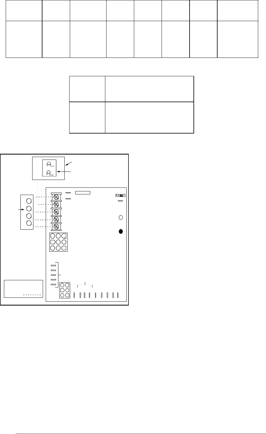
Low Voltage Wiring
Install the thermostat per the manufacturer's
instructions. The low voltage (24 volt) connec-
tions from the thermostat are made at the
terminal strip on the control board in the fur-
nace. See Figure 24 for the proper connections
for heating only (two-wire) and heating/cooling
(four-wire) applications. The recommended
minimum wire gauge for thermostat wiring is
shown in Table 11.
The thermostat must not be installed on an
outside wall or any other location where its opera-
tion may be adversely affected. Adverse affects
include radiant loading from fireplaces, sunlight,
or lighting fixtures, and convective loading from
warm air registers or electrical appliances.
To check the heat anticipator setting either:
1. Add the current draw of the system compo-
nents; or
2. Measure the current flow on the thermostat
R-W circuit after the circulating blower mo-
tor has started.
Set the heat anticipator according to the thermo-
stat manufacturer's instructions for heat antici-
pator settings.
START-UP AND ADJUSTMENTS
Prior to start-up, verify that:
1. The line voltage power leads are securely
connected, that the polarity of the connec-
tions is correct, and that the furnace is
properly grounded.
Field Supplied Disconnect
Within Sight of Furnace
Field Supplied
Panel Connector
Field Supplied
Fused Service
Panel
Black (Hot)
White (Neutral)
Green or Bare
(Ground)
Black
White
Black
White
Black
White
Field Line Voltage
Wiring
Factory Line
Voltage Wiring
Ground Ground Ground
Figure 23. Line Voltage Field Wiring
Table 9. Natural and LP Gas Orifice Sizes
for Elevations between zero and
4999 ft. Above Sea Level
Furnace Rating
Plate Input (Btu/h) Nat LP
45000 44 54
60000 45 55
72000 43 54
96000 43 54
120000 43 54
144000 43 54
Orifice Drill Size
Furnace Ratin
g
Plate Input (Btu/h) Nat LP
45000 44 55
60000 45 56
72000 43 55
96000 43 55
120000 43 55
144000 43 55
Orifice Drill Size
Table 10. Natural and LP gas Orifice Sizes
for Elevations between 5000 and 10,000 ft.
Above Sea Level
26
2. The thermostat wires (R, W, Y, and G) are
securely connected to the correct leads on
the terminal strip of the circuit board.
3. The gas line service pressure does not
exceed 10.0 in. water column (0.36 psig),
and is not less than 4.5 in. water column
(0.16 psig) for natural gas. For LP gas the
line service pressure must not exceed 14 in.
water column (0.51 psig), and must not be
less than 11.0 in. W.C. (0.40 psig).
4. The roll-out and vent safety manual reset
switches are closed. If necessary, press the
red button to reset a switch. See Figure 28
* Time-delay fuses or HACR-type circuit breakers are required.
Table 11. Electrical Data
for location. DO NOT install a jumper wire
across a switch to defeat its function. If a
switch reopens on start-up, DO NOT reset
the switch without identifying and correct-
ing the fault condition which caused the
switch to trip.
5. The blower door is in place, closing the door
switch in the line voltage circuit.
6. The gas line has been purged and all con-
nections are leak tight.
Start-Up Procedure
1. Set the thermostat to the lowest setting.
2. Close the disconnect(s) to provide line volt-
age to the furnace.
3. Follow the procedures given on the operat-
ing instructions label attached to the furnace.
4. Set the thermostat above room tempera-
ture and verify the sequence of operation.
(See the SEQUENCE OF OPERATION.)
5. After the furnace has run for approximately
five minutes, set the thermostat below room
temperature and verify steps (9) through
(11) of the SEQUENCE OF OPERATION.
Verifying and Adjusting
Firing Rate
The firing rate must be verified for each installa-
tion to prevent over-firing the furnace.
NOTE: The firing rate must not exceed the rate
shown on the furnace rating plate. At altitudes
above 2000 ft. the firing rate must be adjusted as
described in the high altitude section.
Figure 24. Low Voltage Field,
Four-wire Heating/Cooling Applications
R C Y G W
A/C Condensing Unit
Condensing Unit
Control Box
Room
Thermostat
Flame Signal Light
(Yellow)
Status Light
(Red)
60
90
120
180
Blower Off
Timing
TWIN
3 Amp
Fuse
COM
24 V
HUM
Neutrals
Low Voltage
Connections 41
52
63
7
8
9
4
5
6
1
2
3
EAC
HUM
M1
M2
M3
COOL
HEAT
L1
XFMR
Unused Motor Leads
EAC
R Y G W
Connect
R & W
For
Heating
Only
FIELD WIRING
NOTE: The "Y"
terminal on the
UTEC control board
must be connected
to the thermostat.
Furnace Cabinet Nominal Maximum Minimum Maximum Minimum Maximum
Input Width Electrical Operating Operating Furnace Wire Fuse or Circuit
(Btuh) (in.) Supply Voltage Voltage Amperes Gauge Breaker Amps*
40,000 14.25 115-60-1 127 103 12.2 14 15
60,000 14.25 115-60-1 127 103 12.2 14 15
80,000 19.75 115-60-1 127 103 14.1 14 15
100,000 19.75 115-60-1 127 103 14.1 14 15
120,000 22.50 115-60-1 127 103 17.3 12 20
Thermostat Recommended Thermostat
Wire Wire Length
Gauge 2-wire 4 or 5-wire
(heating) (cooling)
24 55 ft. 25 ft.
22 90 ft. 45 ft.
20 140 ft. 70 ft.
18 225 ft. 110 ft.
27
thermometer on the supply air side must be
shielded from direct radiation from the heat
exchanger to avoid false readings. Adjust all
registers and duct dampers to the desired posi-
tion and run the furnace for fifteen minutes
before taking any temperature readings. The
temperature rise is the difference between the
supply and return air temperatures.
For typical duct systems, the temperature rise
will fall within the range specified on the rating
plate with the blower speed at the factory recom-
mended setting. If the temperature rise mea-
sured is outside the range specified, it may be
necessary to change the blower speed. Lower
blower speeds will increase the temperature rise
and higher blower speeds will decrease the
temperature rise.
The furnace is equipped with a multispeed mo-
tor. Heating and cooling speed selection is made
by moving the leads on the integrated control
board located in the furnace. The wiring diagram
on the furnace and Figures 25, 26 and 27 show
the speed taps for adjusting motor speed.
If it is desired that the blower operate at the
same speed for heating and cooling, tape off the
terminal of the unused blower wire. Install the
jumper wire, found in the plastic instruction bag,
across the HEAT and COOL taps on the control
board. Reconnect the desired blower tap to the
piggyback quick connect.
The blower control is designed to start the
circulating air blower 30 seconds after the gas
valve is opened. The blower control is factory
wired to turn the blower motor off 120 seconds
after the gas valve is closed. This timing can be
changed using the BLOWER OFF timing switch
opposite the terminal block on the control board.
(See Figure 25.)
Verifying Burner Operation
To verify operation of the burners, make sure
that the blower compartment door is in place and
that there is power to the furnace. Set the
thermostat above room temperature and ob-
serve the ignition sequence. The flame can be
observed through the small clear window on the
burner box. The burner flame should carry over
between all burners. The flames should be blue,
without yellow tips. Flames should extend from
each burner without lifting, curling, or floating.
After verifying ignition, set the thermostat below
room temperature and verify that the burner
flame extinguishes completely.
Use the following procedure to determine the
firing rate:
1. Shut off all other gas fired appliances.
2. Start the furnace and allow it to run for at
least three minutes.
3. Measure the time (in seconds) required for
the gas meter to complete one revolution.
4. Convert the time per revolution to cubic feet
of gas per hour using Table 12.
5. Multiply the gas flow rate in cubic feet per
hour by the heating value of the gas in Btu
per cubic foot to obtain the firing rate in
Btuh. Example:
• Time for 1 revolution of a gas meter with
a 1 cubic foot dial = 40 seconds.
• From Table 9 read 90 cubic feet per hour
of gas.
• Heating value of the gas (obtained from
gas supplier) = 1040 Btu per cubic foot.
• Firing rate = 1040 x 90 = 93,600 Btuh.
6. Adjustments to the firing rate can be
made by adjusting the gas manifold
pressure. See the High Altitude
Application section for additional
information of firing rate at elevations
above 2000 ft.
The manifold pressure must be set to the appro-
priate value for your installation. Refer to either
Table 7 for natural gas or Table 8 for LP/propane
gas to verify the manifold pressure setting re-
quired for your particular installation. To adjust
the manifold pressure, remove the regulator cap
and turn the adjusting screw clockwise to in-
crease pressure or counterclockwise to reduce
pressure. Replace the regulator cap after adjust-
ments are complete.
! CAUTION:
Do not re-drill the burner orifices. If
the orifice size must be changed, use
only new orifices.
Verifying and Adjusting
Temperature Rise
Verify that the temperature rise through the
furnace is within the range specified on the
furnace rating plate. Temperature rises outside
the specified range could result in premature
heat exchanger failure.
Place thermometers in the return and supply air
stream as close to the furnace as possible. The
28
Table 12. Gas Flow Rate
TIME FOR
ONE REVOLUTION
(SECONDS) 1 5 10
24 150 750 1500
26 138 692 1385
28 129 643 1286
30 120 600 1200
32 113 563 1125
34 106 529 1059
36 100 500 1000
38 95 474 947
40 90 450 900
42 86 429 857
44 82 409 818
46 78 391 783
48 75 375 750
50 72 360 720
52 69 346 692
54 67 333 667
56 64 321 643
58 62 310 621
60 60 300 600
62 58 290 581
64 56 281 563
GAS FLOW RATE (C
U
CUBIC FEET PER REVOLUTION OF
METER
TIME FOR
ONE REVOLUTION
(SECONDS) 1 5 10
80 45 225 450
82 44 220 439
84 43 214 429
86 42 209 419
88 41 205 409
90 40 200 400
92 39 196 391
94 38 191 383
96 38 188 375
98 37 184 367
100 36 180 360
102 35 176 353
104 35 173 346
106 34 170 340
108 33 167 333
110 33 164 327
112 32 161 321
114 32 158 316
116 31 155 310
118 31 153 305
120 30 150 300
U
BIC FEET PER HOUR)
CUBIC FEET PER REVOLUTION OF
METER
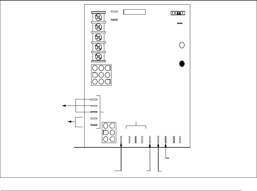
29
Verifying Operation of the Supply
Air Limit Switch
To verify operation of the supply air limit
switch, make sure that the blower door is in
place and that there is power to the furnace.
Completely block the return airflow to the fur-
nace by installing a close-off plate in place of or
upstream of the filter(s). Set the thermostat
above room temperature and verify that the
Sequence of Operation is as described in these
instructions. The supply air limit switch should
function to turn off the gas valve within approxi-
mately five minutes. The circulating air and
combustion blowers should continue to run
when the supply air limit switch opens. Remove
the close-off plate immediately after the supply
air limit switch opens. If the furnace operates
for more than five minutes with no return air, set
the thermostat below room temperature, shut
off the power to the furnace, and replace the
supply air limit switch.
DESCRIPTION OF COMPONENTS
Figure 28 shows the location of each of the
functional components described below. If
any component of the furnace must be re-
placed, use only factory authorized replace-
ment parts. See the Replacement Parts List
for each component.
R C Y G W
Flame Signal
Light (Yellow)
60
90
120
180
TWIN
3 Amp Fuse
COM
24 V
HUM
Neutrals
41
52
63
7
8
9
4
5
6
1
2
3
EAC
HUM
M1
M2
M3
COOL
HEAT
L1
XFMR
Unused Motor
Leads
EAC
Electronic Air Tap
(.5A@ 120 VAC)
Status
Light (Red)
Heating Speed Tap
Cooling
Speed Tap
Humidifier Tap
(.5A@ 120 VAC)
Connect
Neutral
Lead of
Electronic
Air Cleaner
and/or Humidifier
Here.
Common
Leads
Blower Off
Timing
Figure 25. Blower Speed Tap Location
Flame Sensor – The flame sensor acts to prove
that flame has carried over from the ignitor to the
opposite end burner. If no flame is sensed, the
furnace will be shut down automatically.
Gas Valve – The gas valve controls the flow of
gas to the burners. When the gas valve is
energized it automatically opens and regulates
the gas pressure in the manifold.
Pressure Switch – The pressure switch verifies
that the inducer is drawing the combustion gases
through the heat exchanger. It also senses a
blocked condensate drain condition.
Vent Pressure Switch (G6RD Only) – The vent
pressure switch reacts to blockage in the vent or
combustion air piping. It is utilized in G6RD
furnaces only.
Supply Air Limit Switch – The supply air limit
switch prevents the air temperature leaving the
furnace from exceeding the maximum outlet air
temperature.
Vent Safety Switch – The vent safety switch
shuts the furnace down if the outlet flue gas
temperature increases above 160°F. This switch
protects the plastic flue system and the inducer
from over-temperature conditions.
Flame Roll-Out Switch – This switch provides
flame roll-out protection to the furnace and
combustion air inlet pipe.
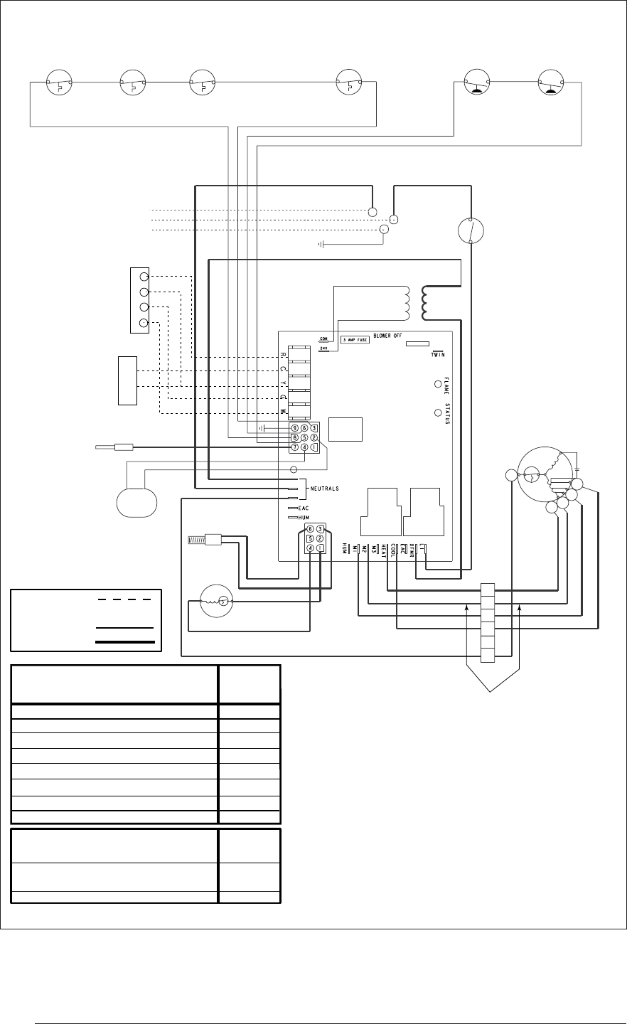
30
For G6RC, G6RD and G6RL Residential Furnaces
Figure 26. G6RC, G6RD and G6RL Integrated Control Board System Diagram
IGNITOR
INDUCER
GAS
VALVE
SUPPLY AIR
LIMIT SWITCH
(ALL MODELS)
VENT
SAFETY
SWITCH
(ALL MODELS)
TRANSFORMER
FLAME SENSOR
C
GREEN
BLACK
WHITE
BLUE BLUE
24 V 120 V
ORANGE
BLUE
BLUE
YELLOW
BROWN
RED
BLACK
WHITE
ORANGE
BLUE
BLACK
ORANGE
BLACK
RED
AIR CONDITIONER
CONDENSING UNIT
BLACK
BLACK
BLOWER DOOR
SWITCH
R
WHITE
BLACK
WHITE W/ BLK STRIPES
BLK W/ WHITE STRIPES
WHITE (NEUTRAL)
BLACK 120V
GROUND
ROOM THERMOSTAT
3 OR 4 SPEED MOTOR
H
MH
ML
L
C
WHITE
RED
ORANGE
BLUE
BLACK
MOTOR
PLUG
1
2
3
4
5
6
BLACK
BLUE
FLAME ROLL-OUT
SWITCH
(ALL MODELS)
VENT
PRESSURE SWITCH
(93+ MODELS ONLY)
PRESSURE
SWITCH
R
Y
G
W
C
Y
180
120
90
60
THESE WIRES ARE
NOT PRESENT
ON 3 SPEED
MODELS
BLOWER
DECK SWITCH
(SELECT MODELS
ONLY)
Legend
Field Wiring
Factory Wiring:
Low Voltage
High Voltage
Power On
Limit Circuit Open
Pressure Switch Stuck Open
Pressure Switch Stuck Closed
Ignition Failure (Check Ground)
115 VAC & Neutral Reversed or no Ground
False Flame or Gas Valve Relay Shorted
ON
1 FLASH
2 FLASHES
3 FLASHES
4 FLASHES
5 FLASHES
Continuous
STATUS
RED
LIGHT
FAULT CONDITION
Power Off
Low Flame Sensor Signal
Flame Present
Continuous
Flash
OFF
ON
FLAME
YELLOW
LIGHT
FAULT CONDITION
If any of the original wire as supplied with
the furnace must be replaced, it must be
replaced with wiring material having a
temperature rating of at least 105 C.
31
MAINTENANCE
It is recommended that the furnace be checked
yearly. At a minimum, this check should include
the following items.
! WARNING:
To avoid electric shock, personal in-
jury, or death, disconnect the electric
power before performing any mainte-
nance.
! WARNING:
Holes in the vent pipe or heat ex-
changer can cause products of com-
bustion to enter the home. Replace
the vent pipe or heat exchanger if
leaks are found. Failure to prevent
products of combustion from being
circulated into the living space can
create potentially hazardous condi-
tions including carbon monoxide poi-
soning that could result in personal
injury or death.
Combustion Air and Vent System
Check the combustion air and vent pipe to
ensure that it is not damaged, corroded or
blocked by debris. Any damaged section of vent
pipe must be replaced, and any obstruction or
blockage must be removed prior to operating the
furnace.
Air Filter(s)
! WARNING:
Never operate the furnace without a
filter in place. Dust and lint in the
return air can build up on internal
components, resulting in loss of effi-
ciency, equipment damage, and pos-
sible fire.
AIR FILTER(S) ARE NOT SUPPLIED WITH THE
FURNACE AS SHIPPED FROM THE FACTORY.
FILTERS FOR SIDE RETURN AND BOTTOM
RETURN APPLICATIONS ARE AVAILABLE
FROM NORDYNE DISTRIBUTORS.
The installer should provide a filter rack for a
high velocity type filter in the return air duct
adjacent to the furnace. Filters should be changed
or cleaned monthly during the heating season.
New or newly renovated homes may require
more frequent changing until the construction
dust has been removed.
Lubrication
The bearings in the circulating air blower motors
are pre-lubricated and sealed at the factory. No
further oiling of the bearings is required for the
life of the motor.
Condensate Drain Assembly
Be sure the condensate lines are free and open
(i.e. avoid kinking hoses). Also make sure all
hose clamps are tight to avoid drawing air into
the system.
Blower Compartment
The blower compartment should be cleaned
monthly during the heating and cooling seasons
to remove any dirt and lint that may have accu-
mulated in the compartment or on the blower
and motor. Dirt and lint can create excessive
loads on the motor resulting in higher than
normal operating temperatures and shortened
service life.
Heat Exchanger and Burner Maintenance
The furnace should operate for many years
without excessive soot buildup in the flue pas-
sageways, however, the flue passageways, the
vent system, and the burners should be in-
spected and cleaned (if required) by a qualified
serviceman annually to ensure continued safe
operation. Particular attention must be given to
identify deterioration from corrosion or other
sources.
SYSTEM OPERATION
INFORMATION
Proper maintenance is most important to achieve
the best performance from a furnace. Follow
these instructions for years of safe, trouble free
operation.
• Do not place combustible materials on or
against the furnace cabinet or the vent
pipe.
• Do not store gasoline or any other flam-
mable vapors and liquids in the vicinity of
the furnace.
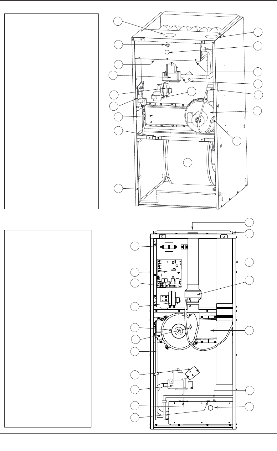
32
Figure 28. Location of Major Components
1 Ignitor (Not Shown)
2 Flame Sensor (Not
Shown)
3 Gas Valve
4 Flame Roll-out
Switch(s)
5 Pressure Switch
7 Control Board
8 Blower Door
Switch
9 Vent Safety Switch
10 Low Voltage
Transformer
11 Supply Air Limit
Switch
12 Circulating Air
Blower Assembly-
13 Induced Draft
Blower
14 Condensate Drain
Tube
15 In-Line Drain
Assembly
16 Burner View Port
17 Front Header Box
18 Combustion Air
Intake
19 Exhaust Vent
G6RC & G6RD Upflow Furnaces
1 Ignitor (Not Shown)
2 Flame Sensor (Not
Shown)
3 Gas Valve
4 Flame Roll-out Switch(s)
5 Pressure Switch
6 Vent Pressure Switch
(G6RD Only, Not Shown)
7 Control Board
8 Blower Door
Switch
9 Vent Safety Switch
10 Low Voltage
Transformer
11 Supply Air Limit
Switch
12 Circulating Air
Blower Assembly-
13 Induced Draft
Blower
14 Condensate Drain Tube
15 In-Line Drain
Assembly
16 Burner View Port
17 Front Header Box
18 Combustion Air
Intake
19 Exhaust Vent
12
3
4
9
10 11
12
17
19
5
7
8
13
14
15
16
18
G6RL Downflow Furnace
1
2
3
4
9
10
11
12
17
19
5
7
8
13
14
15
16
18

33
• Change or replace the air filters monthly
during any period when the circulating
blower is operating regularly.
• Always replace the doors on the furnace
after servicing. Do not operate the furnace
without all doors and covers in place.
• Avoid operating the furnace when win-
dows and doors are open.
• Be sure that the thermostat is properly
installed and is not being affected by drafts
or heat from lamps or other appliances.
Sequence of Operation
Operating sequences for the heating, cooling,
and fan modes are described below. Refer to the
wiring diagrams (Figures 26 and 27) and the low
voltage field wiring diagram (Figure 24).
Heating Mode:
1. On a call for heat the thermostat closes,
applying 24 VAC to the W terminal on the
control board.
2. The control board checks for continuity on
the 24 VAC limit control circuit (over-tem-
perature limit switch, flame rollout switches
and blocked vent switch in series). If an
open limit is detected the control board will
energize the inducer and the conditioned
air blower. All other system functions will be
inoperable until the limit circuit closes. While
the limit is open, the red LED will pulse at
a rate of 1 blink per unit time.
3. The furnace control checks for continuity
across the pressure switch (24 VAC). If the
pressure switch is closed the heat mode
sequence will not continue. If it remains
closed for 10 seconds the red LED will blink
3 times repetitively until the fault condition
clears.
4. The inducer is energized.
5. The pressure switch will close. If the pres-
sure switch does not close after 10 seconds
the fault LED will blink 2 times repetitively
and the inducer will continue to run until the
switch is closed.
6. The inducer will pre-purge for 30 seconds
and then the ignitor will start its warm-up.
After 30 seconds of ignitor warm-up the gas
valve (24 VAC) will open. The ignitor circuit
stays energized for 6 seconds after the gas
valve opens.
7. The furnace control must prove flame via
the flame sensor six seconds after the gas
valve opens. If flame is sensed, all burners
are on and the ignitor cools off. If no flame
is sensed, the gas valve closes immediately
and the inducer continues to run. A second
trial for ignition (step 6) begins if no flame is
sensed. On the fifth try for ignition, the
furnace control is locked out and the red
LED will blink 4 times repetitively. The ther-
mostat must be opened for at least ten
seconds to reset the furnace control after a
lock out. Otherwise, the furnace will attempt
another ignition sequence in 1 hour.
8. The furnace control energizes the circulat-
ing air blower on the heating speed 30
seconds after the gas valve circuit is ener-
gized .
9. When the thermostat has been satisfied,
gas valve is de-energized.
10. The inducer is de-energized after a 30
second postpurge.
11. The furnace control keeps the circulating air
blower energized for 120 seconds (factory
set) or 60, 90, or 180 seconds (field adjust-
able). (See Figure 25.)
12. Abnormal conditions: If a limit opens during
operation, the inducer and circulating air
blower continue to operate. The gas valve is
de-energized immediately. The blowers
continue to operate until the limit closes.
When the limit closes the inducer blower is
de-energized immediately. The circulating
air blower continues to operate for the speci-
fied delay (factory set at 120 seconds).
Cooling Mode:
1. On a call for cooling the thermostat closes,
applying 24 VAC to the G and Y terminals
on the furnace control. This closes the
compressor contactor.
2. The furnace control energizes the circulat-
ing blower (115 VAC) on the cooling speed.
3. When the thermostat is satisfied, the G
and Y terminals on the control board are
de-energized opening the compressor con-
tactor.
4. The circulating air blower is de-energized
after a 90 second delay.
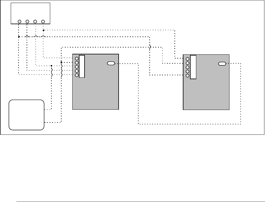
34
Fan Mode:
1. On a call for fan operation, the thermostat
applies 24 VAC to the G terminal on the
furnace control board.
2. The circulating air blower is energized im-
mediately on the heating speed.
3. If the furnace is operated in the continuous
ON position at the thermostat and is then
switched to AUTO, the circulating blower
will operate for a specified delay (factory set
at 120 seconds).
Furnace Fails to Operate
If the furnace does not operate check the follow-
ing:
1. Is the thermostat operating properly?
2. Are the blower compartment door(s) in
place?
3. Is the furnace disconnect closed?
4. Has the circuit breaker tripped or the control
board fuse burned open?
5. Is the gas turned on?
6. Are any manual reset switches open?
7. Is the filter dirty or plugged?
8. Is the flame sensor coated? (Remove and
clean with emery cloth.)
If the furnace locks out after 5 attempts for
ignition, it will try again every hour if a call for
heat remains. If the inducer and circulating air
blowers are operating, and items 1 through 8
have been checked, press the red reset button
on the vent safety switch. (See Figure 28.) If the
furnace operates after depressing the reset
button, contact a qualified serviceman to identify
and repair the problem.
If the furnace continues to not operate, depress
the red reset buttons on the flame rollout switches.
(See Figure 28.) If the furnace operates after
depressing the reset buttons, contact a qualified
servicemen to identify and repair the problem.
Twinning of Two Furnaces
The control board on these furnaces is capable
of being twinned to another G6 furnace, pro-
vided the circuit boards are both UTEC type. If
using UTEC control boards, leave the fuses
installed on each board. The thermostat wires
and the 1/4 inch quick-connect terminals marked
"TWIN" on the furnace controls must be con-
nected together for twinning. (See Figure 29.)
Figure 29. Twinning
W G Y R
Thermostat
A/C
Unit
Twin
Terminal
Twin
Terminal
R
C
Y
G
W
R
C
Y
G
W

35
INSTALLATION/PERFORMANCE CHECK LIST
LOCATION __________________________ CITY ____________________ STATE _____
INSTALLER _________________________ CITY ____________________ STATE _____
UNIT MODEL # _______________________ UNIT SERIAL # ________________________
Minimum Clearances per Table 3? ________
Electrical Connections tight?_____________
Line Voltage Polarity correct? ____________
Supply Voltage: ___________________ Volts
Blower Motor HP: _____________________
FUEL TYPE:
Natural Gas _______ LP/Propane ________
Gas Piping Connections leak-tested? ______
Gas Line Pressure: ____________________
(in. water column, with furnace operating)
Manifold Pressure: ____________________
(in. water column, with furnace operating)
Is there adequate fresh air supply for
combustion and ventilation? _____________
Furnace Input: __________________ (Btuh)
Supply Air Temperature: ____________ (° F)
Return Air Temperature: ____________ (° F)
Temperature Rise: ________________ (° F)
Are Flue Connections tight? _____________
Is there Proper Draft? __________________
Is Vent free from restrictions? ____________
Is the Filter(s) secured in place? __________
Is the Filter(s) clean? __________________
Has the Thermostat been calibrated? ______
Is the Thermostat level? ________________
Is the Heat Anticipator Setting correct? ____
Has the Owner's Information been reviewed
with the home-owner?__________________
Has the Literature Package been left near the
furnace? ____________________________
St. Louis, MO
7079310 (Replaces 7078950)
Specifications and illustrations subject to change
without notice and without incurring obligations.
Printed in U.S.A. (9/99)
¢707931*¤
707931
