Nortec GS Series P User Manual To The 01c11701 37f6 444a 9d01 8515a8f69ae0
User Manual: Nortec GS Series to the manual
Open the PDF directly: View PDF ![]() .
.
Page Count: 78
- 50-79.pdf
- Ta ble Of Con tents
- GEN ERAL 1
- GS in door IN STAL LA TION 3
- - LO CATING AND MOUNTING 4
- - GAS PIPING 5
- - COM BUS TION AIR RE QUIRE MENTS 6
- MAIN TE NANCE 28
- Ta ble Of Con tents
GS Series
Gas Steam Humidifier
Installation,
User & Maintenance
Guide
1506222-D
IMPORTANT: Read and save this guide for future reference. This
guide to be left with equipment owner.
FOR YOUR SAFETY:
Do not store or use gasoline or other flammable vapors and liquids in
the vicinity of this or any other appliance.
WHAT TO DO IF YOU SMELL GAS:
Do not try to light any appliance.
Do not touch any electrical switch; do not use any telephone in your
building.
Immediately call your gas supplier from a neighbor’s telephone.
Follow the gas supplier’s instructions. If you can not reach your gas
supplier, call the fire department.
UNIT OPERATING RANGES:
Max. Ambient Temperature 104ºF (40ºC).
Min. Ambient Temperature 41ºF (5ºC).
Max. Relative Humidity (RH) non-condensing 95% RH.
Min. Relative Humidity (RH) non-condensing 5% RH.
WARNING:
Improper installation, adjustment, alteration, service or maintenance
can cause injury or property damage. Refer to this manual. For
assistance or additional information consult a qualified installer, service
agency, or the gas supplier.
WARNING:
If the information in this manual is not followed exactly, a fire or
explosion may result causing property damage, personal injury or loss
of life.
IMPORTANT:
Read and save this guide for future reference. This guide to be left with
equipment owner.

Table Of Contents
GENERAL 1
- WARNING ................................................1
- DELIVERY ................................................1
- RECEIVING & UNPACKING EQUIPMENT................................1
- GENERAL SPECIFICATIONS ......................................1
- MODEL DESIGNATION .........................................1
MODEL SPECIFICATION 2
GS INDOOR INSTALLATION 3
- LOCATING AND MOUNTING ......................................4
- GAS PIPING ...............................................5
- COMBUSTION AIR REQUIREMENTS ..................................6
- DIRECT VENT GUIDELINES.......................................6
- EXHAUST VENTING ...........................................7
- ADDITIONAL REQUIREMENTS WHEN VENTING THROUGH A SIDEWALL .............11
- ELECTRICAL ..............................................12
- PRIMARY WIRING ...........................................13
- LOW VOLTAGE CONTROL WIRING .................................14
- CONTROL INSTALLATION .......................................15
- PLUMBING ...............................................15
- FILL WATER SUPPLY LINE ......................................15
- DRAIN LINE ...............................................15
- AUX DRAIN PORT ...........................................16
-STEAM LINES AND CONDENSATE LINE ...............................16
GS OUTDOOR INSTALLATION 16
- MOUNTING ...............................................16
-TYPICAL GSTC OUTDOOR INSTALLATION ..............................17
- ROOF CURB DIMENSIONS ......................................18
- GAS PIPING...............................................19
- EXHAUST VENTING ..........................................20
- ELECTRICAL INSTALLATION .....................................20
- FILL WATER SUPPLY LINE ......................................21
- DRAIN LINE ...............................................21
- AUXILIARY DRAIN ...........................................21
- STEAM LINES..............................................22

PRINCIPLE OF OPERATION 22
- COMBUSTION .............................................22
- WATER MANAGEMENT ........................................22
- START UP PROCEDURE .......................................23
- FILLING THE SYSTEM .........................................23
- TESTING THE IGNITION SAFETY SHUT-OFF.............................23
- STARTING THE HUMIDIFIER .....................................24
- TAKING OUT OF OPERATION .....................................24
- INSTALLATION CHECKLIST ......................................25
- SCALE MANAGEMENT .........................................27
- WATER QUALITY ............................................27
- FAULT CONDITIONS ..........................................28
MAINTENANCE 28
- DRAINING THE TANK .........................................28
- MANDATORY MAINTENANCE SCHEDULE ..............................29
- CLEANING THE TANK .........................................30
- SERVICING THE UNIT .........................................31
- SERVICE CHECKS ...........................................31
- COMPONENTS REPLACEMENT....................................32
-Hot Surface Igniter and Flame Sensor Replacement ........................32
-Burner Removal and Installation ...................................32
-Removal and Installation of the Combustion Blower.........................33
-Gas Valve Replacement .......................................33
-Air Switch Replacement .......................................34
-Float Chamber Replacement ....................................34
-Transformer Replacement ......................................35
-Fill Valve Replacement .......................................35
-Drain Pump Replacement ......................................36
-Fill Box Replacement ........................................36
-Removal of the Heat Exchanger ...................................37
- DIP SWITCH SETTINGS ........................................38
- SOFTWARE FLOW CHART ......................................39
- FAULT AND WARNING LIST ......................................60
- EXPLODED VIEW INTERNAL COMPONENTS SPARE PARTS ....................63
- EXPLODED VIEW INDOOR CABINETRY SPARE PARTS.......................66
- EXPLODED VIEW OUTDOOR CABINETRY SPARE PARTS .....................68
- GS QUICK REFERENCE ........................................72
GENERAL
This installation guide has been designed to
provide assistance when installing, mounting, and
commissioning a GS Series humidifier. Actual on site
application may vary. Consult Technical Services or
your local NORTEC representative.
WARNING
·Improper installation, adjustment, alteration,
service, maintenance, or use can cause carbon
monoxide poisoning, an explosion, fire, electrical
shock, or other conditions which may cause
personal injury or property damage. Consult a
qualified installer, service agency, local gas
supplier, or your distributor or branch for
information or assistance. The qualified installer
or agency must use only factory authorized and
listed kits or accessories when modifying this
product. A failure to follow this warning can
cause electrical shock, fire, personal injury, or
death.
·Should overheating occur, or the gas fail to shut
off, shut off the manual gas valve to the appliance
before shutting off the electrical supply.
·Do not use this appliance if any part has been
under water. Immediately call a qualified service
technician to inspect the appliance and to replace
any part of the control system and any gas
control which has been under water.
DELIVERY
The standard delivery includes:
·Gas Steam humidifier equipped with desired
options.
·In a bag you will find:
- Manuals.
- Adapter fittings for water connection.
- Steamhose for steam outlet with clamps.
- Hose and clamps for drain connection.
·The GS Indoor Series offers an optional
telescopic stand mounted inside the unit legs.
Stand cross bracing are shipped with the unit.
·The GS Outdoor Series comes with all required
venting to be installed on site.
·Desired accessories ordered.
RECEIVING & UNPACKING EQUIPMENT
·Check packing slip to ensure ALL material has
been delivered.
·All material shortages are to be reported to
NORTEC within 48 hours from receipt of goods.
NORTEC assumes no responsibility for any
material shortages beyond this period.
·Inspect shipping boxes for damage and note on
shipping waybill accordingly.
·After unpacking, inspect equipment for damage
and if damage is found, notify the shipper
promptly.
·All NORTEC products are shipped on an F.O.B.
factory basis. Any and all damage, breakage or
loss claims are to be made directly to the
shipping company.
GENERAL SPECIFICATIONS
The NORTEC GS Series humidifier is a
completely new patented design based on leading
edge technology. The GS is designed to provide clean
steam humidification at an economical price.
The GS Series humidifiers are designed
exclusively for humidification in ventilation systems or
direct room humidification. Any other type of
application, without the written consent of Nortec or
your Nortec agent, is considered as not conforming
with the intended purposes. The manufacturer/
supplier can not be made liable for any damages
resulting from improper use.
-1-
MODEL DESIGNATION
The unit specification label indicates the model of
gas humidifier according to the following chart:
GS 100 N DV
PRODUCT LINE
(Gas Steam Humidifier)
Humidifier size (lbs/hr)
FUEL
N
= NATURAL GAS
P = PROPANE GAS
DIRECT VENT
OPTION
TC = Total Controller
c/w KEYPAD
P = Economical
TC
100
200
300
400
500
600
O
C
OUTDOOR MODEL
-2-
MODEL GS 100 SPECIFICATIONS
FUEL BLOWER SPEED INPUT (BTUH)* STEAM CAPACITY (LBS/HR) MANIFOLD PRESS. IN W.C.
NATURAL GAS MAX 140,000 105 -0.05
MIN 45,000 25 -0.05
PROPANE MAX 140,000 105 -0.35
MIN 50,000 25 -0.35
MODEL GS 200 SPECIFICATIONS
FUEL BLOWER SPEED INPUT (BTUH)* STEAM CAPACITY (LBS/HR) MANIFOLD PRESS. IN W.C.
NATURAL GAS MAX 280,000 210 -0.05
MIN 45,000 25 -0.05
PROPANE MAX 280,000 210 -0.35
MIN 50,000 25 -0.35
MODEL GS 300 SPECIFICATIONS
FUEL BLOWER SPEED INPUT (BTUH)* STEAM CAPACITY (LBS/HR) MANIFOLD PRESS. IN W.C.
NATURAL GAS MAX 420,000 315 -0.05
MIN 45,000 25 -0.05
PROPANE MAX 420,000 315 -0.35
MIN 50,000 25 -0.35
MODEL GS 400 SPECIFICATIONS
FUEL BLOWER SPEED INPUT (BTUH)* STEAM CAPACITY (LBS/HR) MANIFOLD PRESS. IN W.C.
NATURAL GAS MAX 560,000 420 -0.05
MIN 45,000 25 -0.05
PROPANE MAX 560,000 420 -0.35
MIN 50,000 25 -0.35
MODEL GS 500 SPECIFICATIONS
FUEL BLOWER SPEED INPUT (BTUH)* STEAM CAPACITY (LBS/HR) MANIFOLD PRESS. IN W.C.
NATURAL GAS MAX 700,000 525 -0.05
MIN 45,000 25 -0.05
PROPANE MAX 700,000 525 -0.35
MIN 50,000 25 -0.35
MODEL GS 600 SPECIFICATIONS
FUEL BLOWER SPEED INPUT (BTUH)* STEAM CAPACITY (LBS/HR) MANIFOLD PRESS. IN W.C.
NATURAL GAS MAX 840,000 630 -0.05
MIN 45,000 25 -0.05
PROPANE MAX 840,000 630 -0.35
MIN 50,000 25 -0.35
MODEL SPECIFICATION
-3-
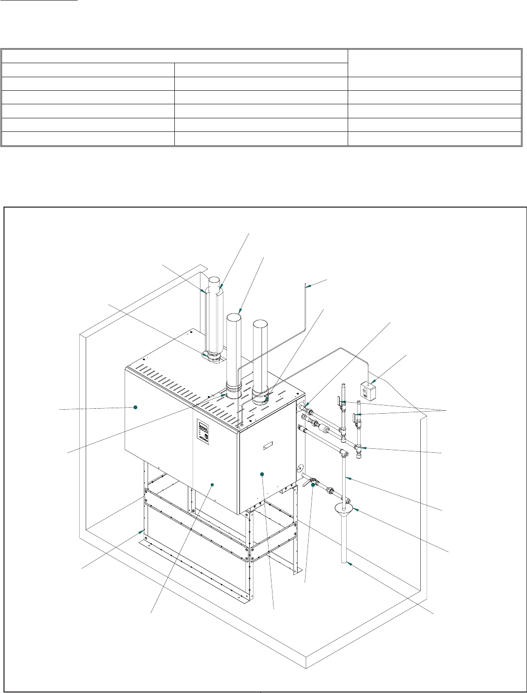
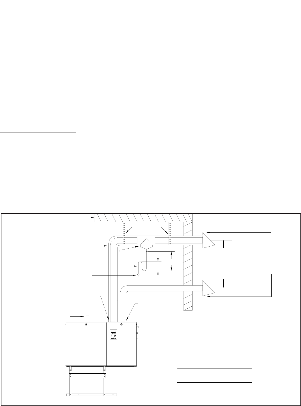
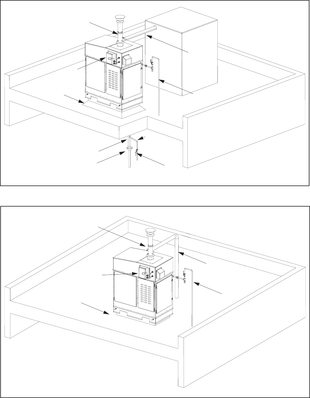
Snap on Installation
Steamline
Steam Outlet
B or BH Venting Type
Control Wiring
Main Power Disconnect
Shut Off
To Drain
Auxiliary Drain
Air Gap with Funne
l
Service Access Door
(Mechanical)
Service Access
Door (Electrical)
Clean Out
Access Door
Optional Stand
Drain
Gas Line
Connection
Fresh Water
Fill Line
3/4"min 30-80 psi
Exhaust Outlet
Optional
Direct Vent
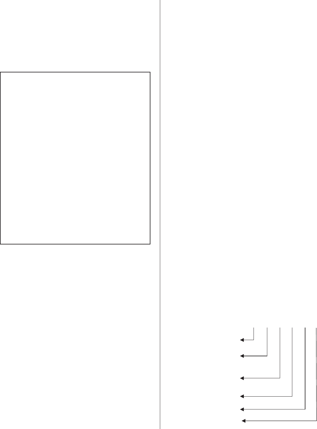
Figure #1
Typical Installation (Indoor)
HIGH ALTITUDE - A derate in input exists for installations at higher altitudes. For Canadian models, an automatic
10% derate applies to installations from 2000-4500 feet. For U.S. Models, refer to the chart below for high altitude
derate information.
FOR U.S. MODELS ONLY
Altitude Derate %
Feet Meters
0-2000 0-610 0
2001-3000 610-915 8
3001-4000 915-1220 12
4001-4500 1220-1370 16
4501-higher 1370-higher Contact Factory
INDOOR INSTALLATION
The installation must conform with local building
codes or, in the absence of local codes, with the ANSI
Z223.1, National Fuel Gas Code, and/or CAN/CGA
B149 Installation Codes. Refer to the Gas Piping
section of this manual.
LOCATING AND MOUNTING
GS Series humidifiers are designed for floor
mounting or on a GS Stand (optional). The clearance
dimensions shown in this manual are for reference
only and are the minimum required for maintenance of
the humidifier. Local and National Codes should be
consulted prior to final location and installation of the
humidifier. NORTEC cannot accept responsibility for
installation code violations.
Figure #1 shows a typical installation with all
required connections to the GS Humidifier. Careful
consideration should be given to all of these
connections when choosing a location for the
humidifier.
WARNING: During installation cover the
humidifier to prevent any dust or other
contaminants from entering the cabinets when
activities such as drilling are taking place.
·Ambient temperature location for humidifier:
41ºF - 104ºF (5ºC - 40ºC).
·Relative humidity location for humidifiers:
5% rh - 80% rh.
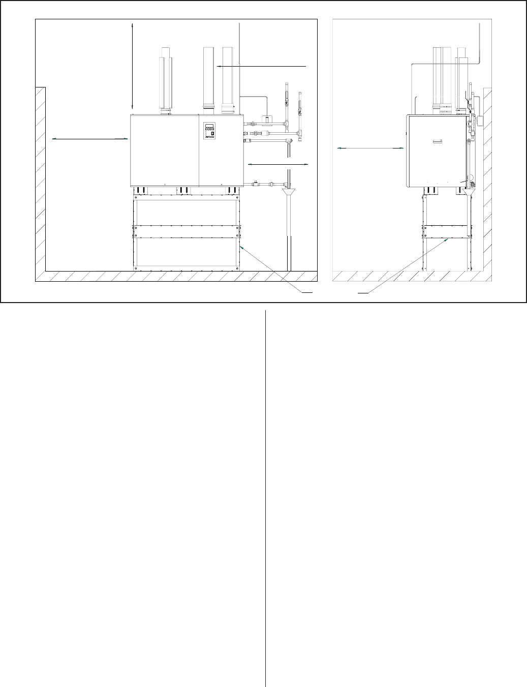
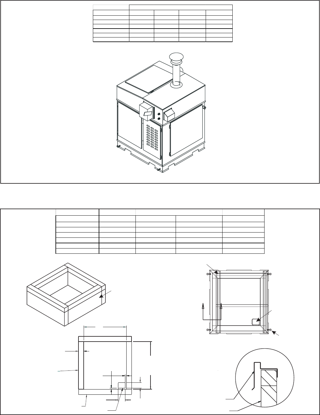
·All GS humidifiers are rated for the clearance to
shown in Figure #2.
·Location of the steam distributor should be
minimum of 36” above the humidifier.
·DO NOT locate humidifier any further than
absolutely necessary from steam distributor
location. Net output will be reduced as a result of
heat loss through steam line. Also, increased
static pressure (over 12" W.C.) will result in hot
water going down the drain. Consult factory if this
situation occurs.
·Where possible, mount humidifier at a height
convenient for servicing.
·Make sure the humidifier is mounted level.
·DO NOT mount humidifier on hot surfaces.
·The humidifier must be installed so that all
electrical components are protected from
exposure to water.
-4-
O
p
tional Stand
Minimum
36" (91.5 cm)
Right
30" (76.2 cm)
Minimum
4" (10.2 cm) to vent pipe
Left
36" (91.5 cm)
Required only for
GSTC/GSP
500/600
Front
30" (76.2 cm)
Front Clearance
Side Clearance
Figure #2
Clearance Requirements
·DO NOT mount humidifiers in an area where
freezing may occur.
·If humidifiers are mounted on a roof, a properly
ventilated, temperature controlled, (above
freezing), weatherproof enclosure must be used.
·DO NOT mount humidifiers on vibrating surface.
Consult factory.
·The humidifier shall not be installed directly on
carpeting, tile or other combustible material other
than wood flooring.
·Some insulating materials may be combustible.
Prior to installing this appliance examine the area
for insulating material. If this appliance is
installed in an insulated space, it must be kept
free and clear of insulating materials. If insulation
is added after the appliance is installed, it will be
necessary to examine the area again.
GAS PIPING
Installation of piping must be in accordance with
local codes, and ANSI Z233.1, “National Fuel Gas
Code,” in the United States or CAN/CGA-B149
Installation Codes in Canada.
The following table indicates the maximum and
minimum allowable gas pressures for the Gas
Humidifier.
The gas inlet pipe size to the appliance is:
½” NPT for GS 100
¾” NPT for GS 200
1” NPT for GS 300 / 400
1 ¼” NPT for GS 500 / 600
Provide an adequate size gas supply line.
In all installations, a certified manual shut off
valve, located outside the cabinet, must be installed.
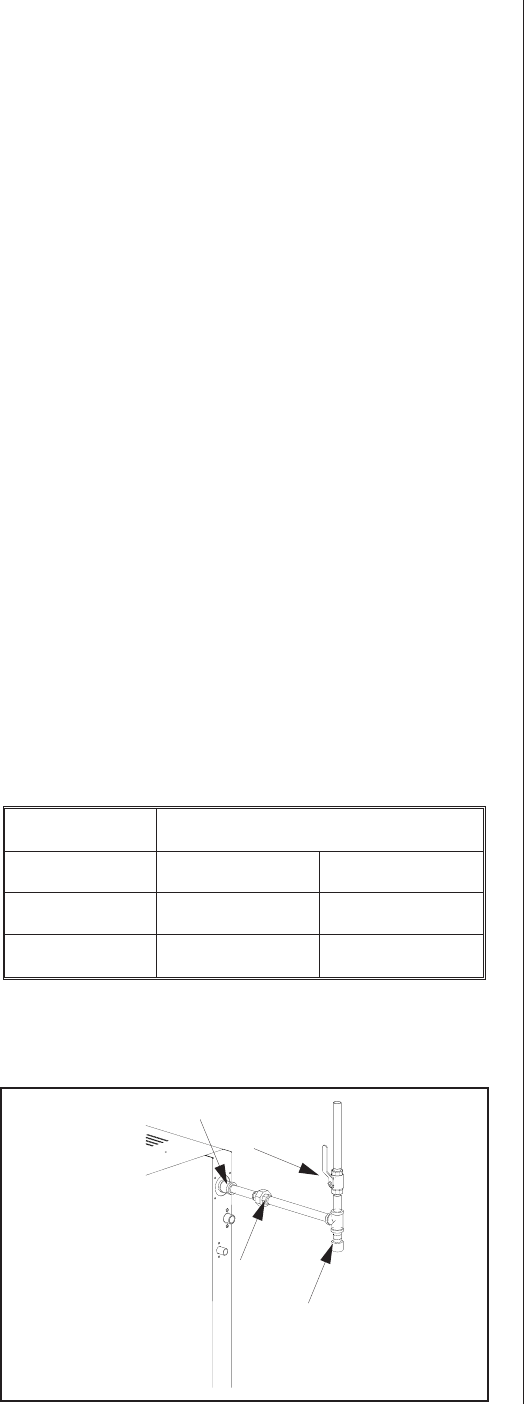
When black iron gas pipe is used, a sediment trap
must be located ahead of the humidifier gas controls.
See Figure #3.
Leak test all gas connections external to the
humidifier, using a commercial soap solution made to
detect leaks. Bubbles indicate gas leakage. Seal all
leaks before placing the humidifier in operation.
WARNING: Never use an open flame to check for
gas leaks. If a leak does exist, a fire or explosion
could occur, resulting in damage, injury or death.
The appliance must be isolated from the gas
supply piping system by closing its individual manual
shut-off valve during any pressure testing of the gas
supply piping system at test pressures equal to or
greater than 14” w.c. (3.5 kPa).
Dissipate test pressure from the gas supply line
before re-opening the manual shut off valve to the
appliance.
NOTES: (See pg 19 for additional Gas Piping
information)
·Failure to follow this procedure may damage the
gas valve. Over pressured gas valves are not
covered by warranty.
·DO NOT use Teflon tape on gas line pipe
threads. A flexible sealant suitable for use with
Natural Gas and Propane Gas is recommended.
·Plan gas supply piping so it will not interfere with
removal of gas valves or blower assemblies and
front or side service doors.
·All gas piping should be adequately supported to
prevent any strain on inlet piping.
The gas valve is provided with pressure taps to
measure gas pressure upstream and downstream,
(manifold pressure). The minimum gas pressure
shown is for the purpose of input adjustment.
A 1/8" NPT plugged tapping, accessible for test
gage connection, must be installed immediately
-5-
INCHES W.C.
GAS MIN. MAX.
Natural 4.5 9.0
Propane 9.0 13.0
Shut-off Gas Valve
(by others)
Sediment Trap
(by others)
Inlet coupling supplied
Union
(by others)
Figure #3
Gas Connection
upstream of the gas supply connection to the
appliance.
COMBUSTION AIR REQUIREMENTS
Provide for adequate combustion and ventilation
air in accordance with Sections 8.3, Air for Combustion
and Ventilation, of the National Fuel Gas Code, ANSI
Z223.1, or Sections 7.2, 7.3, 7.4 of CAN/CGA B149
Installation Codes, or applicable provisions of the local
building codes.
The required free area of supply air opening is:
13 in. sq. (8,387 mm2), for GS 100
23 in. sq. (14,839 mm2), for GS 200
35 in. Sq. (22,581 mm2), for GS 300
47 in. Sq. (30,323 mm2), for GS 400
59 in. Sq. (38,064 mm2), for GS 500
71 in. Sq. ( 45,806 mm2), for GS 600
Cabinet top and bottom contain air openings to
provide combustion air to the forced draft blower. DO
NOT BLOCK THESE OPENINGS.
Excessive exposure to contaminated combustion
air will result in safety and performance related
problems. Known contaminates include halogens,
ammonia, and chlorides, excessive dust, lime or dirt.
Excessive exposure of electronics to the contaminants
will also result in performance related problems.
Contact NORTEC Technical Services if you have any
questions. If contaminants exist, isolate the unit from
the contaminated space.
DIRECT VENT GUIDELINES
Installation of the combustion air supply line must
be carried out by adequately qualified personnel. All
local regulations relating to the provision of air supply
systems must be observed and adhered to.
The maximum pipe length for the air supply line
and exhaust is equivalent to 70’ (21m). The vent pipe
diameter must be maintained over the overall length of
the vent.
All air piping must be listed type for direct vent
application with sealed joints and seams, such as Z
flex.
The air supply line should be approximately as
long as the flue gas venting and must be supported at
every 5 ft. (1.5 m) and additionally at every pipe bend.
The air supply line must be installed with air
supply terminals provided.
At low temperatures, water condensation can form
on the outside of the pipe. To prevent this, it is
recommended that the supply air line is insulated and
an in line heat is added. Consult factory.
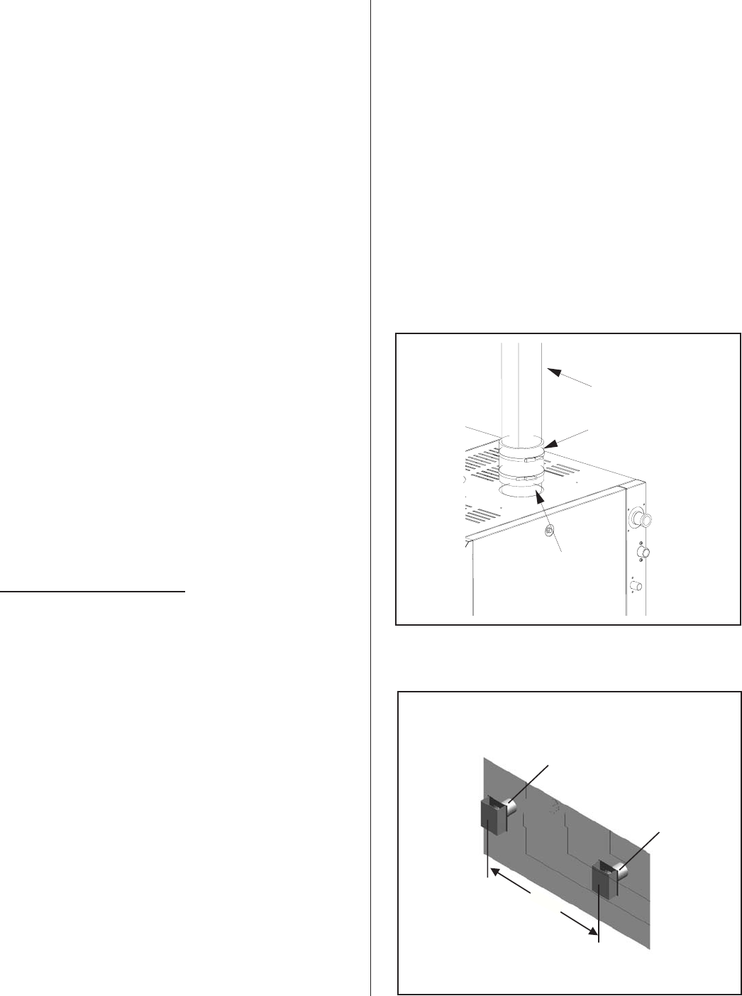
Attach the air supply line to the manifold using a
hose clamp or hose coupling if required. See Figure
#4.
WARNING: Air supply line should not obstruct
any services going to the humidifier front and
right side cabinet panels.
WARNING: BH Type venting must be used in
a direct vent application.
The air intake terminal and the flue gas terminal
must end at an outside location. See Figure #5.
-6-
Air Piping Insulated
(by others)
Hose Coupling
(by others)
Air Intake Connection
4ft-6ft
(1.2 m - 1.83 m)
Exhaust terminal with
opening vertical.
Intake terminal with
opening vertical.
Keep 6“ (15.2 cm)
away from sidewall.
Figure #5
Direct Vent Side Wall Requirements
Location of air intake and flue gas terminal must
comply with all local and national regulations.
EXHAUST VENTING
The GSTC and GSP are classed category I and III
fan assisted gas appliances. This allows two methods
of venting. Listed below are instructions for both
venting systems, followed by specific requirements for
each system.
Review the requirements for both category I and III
installations and select the venting method best suited
for the installation.
Category III class must be used in direct vent
applications.
GENERAL REQUIREMENTS
·The vent systems shall be listed to UL or UL/CSA
standard and meet the installation requirements
of the National Fuel code in the USA ( ANSI
Z223.1) and the Canadian Standards
CAN/CGA.B149 Installation Codes. Any local
jurisdictions reflecting changes to the above
codes should be observed.
·In applying the codes, reference should be given
to the venting manufactures instructions, the
serving gas supplier regulations, and the specific
instructions provided in this manual.
·This appliance must be installed to comply with
national regulations and codes. A qualified
technician, competent with these codes and the
local requirements of the jurisdiction must carry
out the installation.
·Proper removal of combustion gases must be
assured, and building materials must be
protected from degradation by flue gases.
·Never mix venting types. (B to BH or visa versa.)
Never use two different manufacturer’s
equipment for the same chimney.
·All vent runs should be as direct as possible with
no more than 6 elbows in the system.
·Maintain an upward slope of ¼” per ft on all
horizontal vent pipe runs.
·This gas humidifier may not be used in
conjunction with a power venter or draft inducer.
-7-
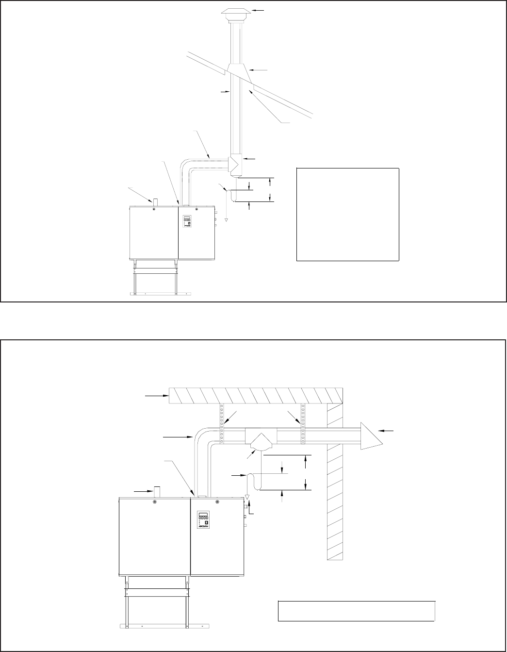
Trap
Wall
BH type vent using double wall vent
with all joints being air and water tight.
Reference local and/or national codes
before installation of the vent
Condensate tee and trap must
be installed. Take the condensate
to a floor drain or a condensate pump
Hangers straps
Exhaust venting must
be min.4 ft, max.6 ft
in distance apart from
the fresh air intake
for direct venting
BH type double wall with double
wall connectors required.
Note: These are
g
uidelines onl
y
. Follow the local and/or national codes in
y
our respective area.
Terminations
supplied with
unit
Direct vent
Inlet
Exhaust venting outlet
Steam
Outlet
Condensate
Tee 2ftMin
3” Min
Figure #6
Horizontal Venting Using a Direct Vent Application Using BH Type Only
-8-
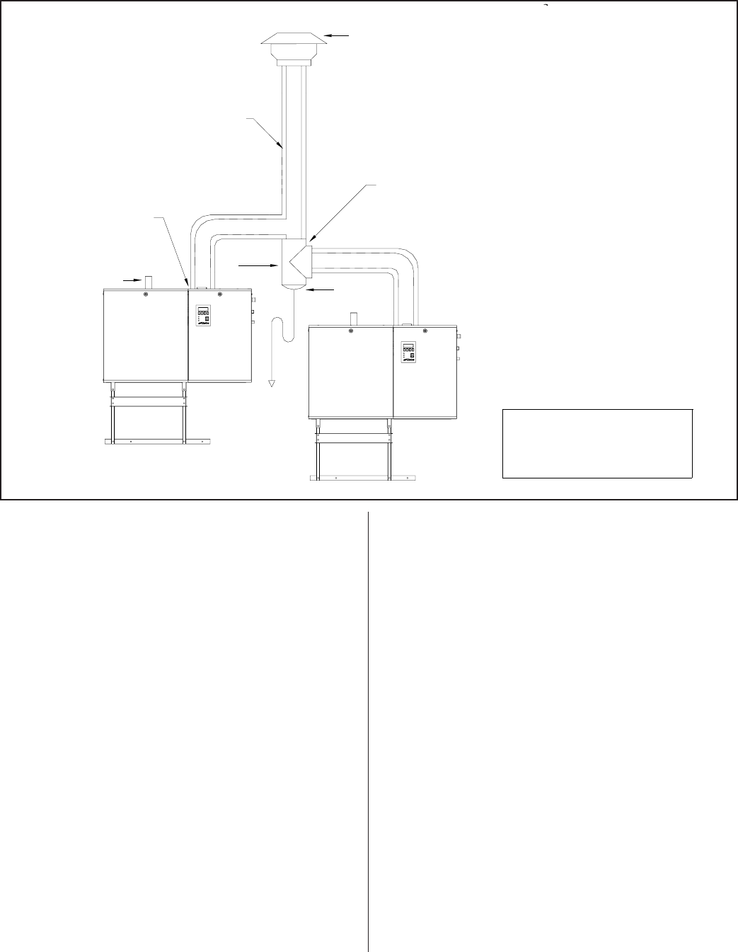
Trap
UL Listed Cap
Required
Condensate tee and
trap must be installed.
Take the condensate to
a floor drain or a
condensate pump.
B type double wall vent with
double wall connectors required
for category I appliances.
Limitations on horizontal
distance when venting with B
vent
BH type double wall vent with
double wall connectors required
and all joints are to be air and
water tight. BH vent is a category
III appliances
Flashing
4" minimum air
space required
B or BH type vent using double wall vent
with double wall connectors is required.
Reference local and/or national codes
before installation of the vent.
Condensate tee
required
Steam Outlet
Exhaust venting
outlet
Horizontal run
1/4"rise per ft
2 FT Min
3” Min.
Wall
Hangers Straps
Condensate
Tee
Condensate tee and trap
must be installed. Take
the condensate to a floor
drain or a condensate
pump.
BH type vent using double wall vent
with all joints being air and water tight.
Reference local and/ or national
codes before installing vent
Trap
BH type double wall vent with double wall
connectors is required for category III appliances
Note: These are guidelines only, follow the local and/or national codes in your respective area.
Steam Outlet
Exhaust venting outlet
Nortec vent terminal
2 ft Min.
3” Min.
Figure #7
Vertical Venting Application Using B or BH Venting
Figure # 8
Side Wall Venting Application Using BH Type Only
·For any vent lengths over 20 feet long, insulate
the vent pipe to reduce the amount of condensate
that could form in the flue gases.
·When the venting passes through a cold area, or
location that has large amounts of air passing
over the venting, it should be insulated to prevent
condensation from forming inside the venting.
·Vent pipe passing through walls, floors, and
ceilings, must be installed with the proper
clearances from combustible materials, and
venting manufactures fire stop equipment.
·The venting shall not pass through any circulation
air duct or plenum.
WARNING: Provide a screen or barrier to prevent
personal injury in areas where personnel may come
into contact with hot vent pipes.
·A drip “T” or flue box condensate port should be
used for condensate removal. When a
condensate drain is used it will be necessary to
install a trap to prevent flue gases from escaping.
Install a trap with a minimum 12” standing
water column.
·Prior to activating the appliance, ensure that the
trap is filled with water and that the drain
terminates in accordance with local plumbing
codes.
·Never vent into a unlined masonry or concrete
chimney.
·Chimney or vent should extend at least 3’ (1 m)
above a roof and at least 2’ (.6 m) above any
ridge within 10’ (3 m) of the chimney. Local codes
apply.
·Install venting so as to prevent accumulation of
condensate and have a means for condensate
removal.
·Plastic, PVC, CPVC and HTPV special gas vents
are not approved for use with this appliance.
·The vent must terminate at a sufficient height
above the roof to prevent blockage by expected
snowfall.
-9 -
UL Listed Cap
Required
Category I gas appliance uses
B type venting. Follow local
and/or national codes for
venting installation.
B type double wall vent
with double wall
connectors is required for
category I, serving two or
more gas appliances.
Condensate tee and trap
must be installed. Take
the condensate to a floor
drain or a condensate pump.
Steam Outlet
Exhaust venting
outlet
Note: These are guidelines only. Follow local and/ or national codes in your respective area.
Condensate
Tee
Trap
Figure # 9
Co-venting Application Using B Vent Only
·Vent pipe must be secured with hangers or pipe
straps
·All horizontal runs must be adequately supported
with hangers or straps to prevent sagging.
Installation as a Category I Appliance
·The GS series humidifiers have a fan-assisted
combustion which operates with a non-positive
vent static pressure when installed with the
appropriate vent diameter.
·Category I appliances must be vented vertically
or nearly vertical. (See Figure #7 & #9)
·This category appliance is restricted to vertical
venting installations with limits placed on
horizontal lengths and vent diameters. Refer to
the tables in local and/or national codes. No
sidewall termination is accepted.
·Vent piping must be UL or UL/CSA listed type B
or B-W.
Recommended B-Venting Manufacturers
1. Simpson Dura-Vent
2. Selkirk Canada Corporation
3. American Metal Products
4. Metal-Fab Inc.
·The vent pipe exiting the humidifier is sized for
Category III installations. A field supplied adapter
is required to increase the pipe immediately at
the exit of the humidifier. The vent pipe must be
expanded to the minimum sizes listed below for
each model, increasing as code requires.
GS 100 4” minimum diameter
GS 200 5”
GS 300/400 7”
GS 500/600 8”
·The termination at the humidifier is a MALE
connection. Standard venting hook-ups require a
female path. It is highly recommended that a
female to female adapter be assembled onto the
humidifier to establish the proper venting
sequence. Consult with the venting manufacturer
for proper hook up.
·Vent connectors shall not be connected into any
portion of a mechanical draft system operating
under positive pressure.
·Use only double wall (aluminum inner wall) B
vent. Single wall venting can not be used due to
the increased wet time in the lining. If the vent
connector attaches to a lined masonry chimney,
the chimney must be sized and installed
according to the provisions of the National Fuel
Gas Code or Canadian CAN/CGA.B149
standards.
·An approved venting manufacturers termination
cap for the stack outlet must be used.
·The maximum flue temperature is 400 degrees F.
Normal operating range is 360 to 380 degrees F.
·When the category I installation is selected it may
be commonly vented with other listed gas fire
appliances. Total input rates of all appliances will
determine the vent size the chimney must be
sized and installed according to the provisions of
the National Fuel Gas Code or Canadian
CAN/CGA.B149 standards.
·A maximum of 4 gas appliances may be common
vented on the same floor. Multiple story common
venting is not recommended.
·Refer to the vent manufacturers instructions for
proper clearances to combustibles.
-10-
Female to Femal
e
Adapter
(by others)
Figure #10
Exhaust Connection

·This appliance should not be connected to a
chimney flue servicing a separate appliance
designed to burn solid fuel. Never connect this
humidifier to a chimney servicing a fireplace.
·This venting category cannot be used in direct
vent applications.
Installation as a Category III Appliance
·This venting system can be installed horizontally
or vertically and can terminate on a rooftop or
sidewall provided the NFGC (Nation Fuel Gas
Code) and CAN/CGA- B149 codes are followed.
The venting manufacturer instructions must also
be followed. See Figure # 6,#7 & #8.
·This venting must be used in all direct vent
applications.
·This category installation may not be common
vented with any other natural draft gas appliance
or power assist appliance. The humidifier cannot
share a chimney flue servicing an appliance
designed to burn solid fuel.
·Venting must be UL or UL/CSA listed, tested to
ULC-5636 Standard. Venting may be BH or L
vent. Special gas vent shall be listed and installed
in accordance with the terms of the special gas
vent listing and the manufacture’s instructions.
The special instructions listed below should be
followed as well.
·All joints must be sealed using high temperature
RTV silicone.
BH Vent Manufacturers
1. Flex-L International
2. Fas-N Seal
3. Heat-Fab Inc.
4. Z Flex
·The gas humidifier is supplied with the following
exhaust outlets.
GS 100 3”
GS 200 4”
GS 300/400 5”
GS 500/600 6”
·The venting must remain the same diameter
throughout the installation.
WARNING: Provide a screen or barrier to prevent
personal injury in areas where inadvertent personnel
contact with vent pipe can occur.
·A minimum equivalent vent length of 7 feet must
be connected to the humidifier. Vent lengths
must not exceed 100’ (30 m). Each 90° elbow
is equivalent to 10’ and each 45° elbow equals 5'.
The vent run should be as direct as possible with
no more than 6 elbows in the system.
·Diret vent applications, length of vent should not
exceed 70” in equivalent length.
ADDITIONAL REQUIREMENTS WHEN VENTING
THROUGH A SIDEWALL
For sidewall venting, locate the humidifier as close
as possible to the wall being used.
Locate the vent terminal at least three feet above
any forced air inlet located within ten feet; or at least
four feet below, four feet horizontally from, or one foot
above any door, window, or gravity air inlet into any
building.
A minimum horizontal clearance of four feet from
electric meters, gas meters, regulator and relief
equipment is required.
For sidewall vent terminations, the humidifier must
be installed with the certified vent terminal that can be
purchased from Nortec.
GS 100 3” Nortec P/N 1502321
GS 200 4” Nortec P/N 1502322
GS 300/400 5” Nortec P/N 1507320
GS 500/600 6” Nortec P/N 1507321
Locate the vent terminal at least seven feet above
grade when it is adjacent to public walkways.
Locate the bottom of the vent terminal at least
twelve inches above grade or ground, or normally
expected snow accumulation level. The snow level
may be higher on walls exposed to prevailing winds.
Avoid areas where local experience indicates that
condensate drip may cause problems such as above
planters, patios, or over public walkways, or over an
area where condensate or vapor could create a
nuisance or hazard, or could be detrimental to the
operation of regulators, relief valves, or other
equipment. Refer to the vent manufacturer's
installation instructions.
-11-

The vent terminal must be installed in the same
atmospheric pressure zone as the combustion air inlet
of the humidifier. If this is not possible (as in cases of
positive or negative room pressures) the humidifier
should be installed with the direct vent option.
ELECTRICAL
PRIMARY WIRING
All work concerning the electrical installation
must be performed by qualified personnel.
WARNING: The electrical parts inside the
humidifier are very sensitive to electrostatic discharge.
Appropriate measures against electrostatic discharge
(ESD protection) must be taken when carrying out
installation work.
·The humidifier should only be connected to
primary power (mains power) after all installation
work has been completed.
·An external disconnect switch must be installed
close to the unit to allow for power interruption
during servicing and/or maintenance.
·Humidifiers require field wiring to primary voltage
terminal blocks. Power requirement must be
120V or 208-240 Vac, 15A separately fused
circuit, single phase. Use only copper wire with a
minimum 70 °C (158 °F) temperature rating.
Wiring can be fed through a 7/8" hole on the
bottom or the top of the control compartment.
See Figure #1.
·When installed, the appliance must be electrically
grounded in accordance with local codes or, in
the absence of local codes, with the National
Electrical Code, ANSI/NFPA 70, and/or the CSA
C22.1 Electrical Code, if an external electrical
source is utilized.
·External wiring sizes must be in accordance with
NEC and/or CEC and existing local electrical
codes and by-laws.
LOW VOLTAGE CONTROL WIRING
All GS models require at least one type of input
control signal for unit operation. Refer to the sections
below that detail the types of controls that can be used
with each model.
Low voltage control terminal strips are provided in
the electrical compartment. Internal sides are factory
wired. External sides are to be field wired. Refer to
the specific control-wiring diagram supplied with each
unit.
Field wiring from humidistat to humidifier and
between devices should be shielded 18 AWG or
heavier and kept as short as possible.
Controls are available from NORTEC as
accessories and can be ordered with the humidifier.
Controls by others may also be used as long as they
meet the criteria noted below. The following is a
summary of the common types of controls that may be
used with NORTEC Gas Humidifiers.
Wall or Duct Mounted Control On/Off
Humidistat: Wired to make on drop in humidity,
break on rise to setpoint. Set to desired RH. Can
be a make/break set of contacts from a Building
Automation System.
Duct Mounted Safety High Limit On/Off
Humidistat: Wired to make on drop in humidity,
break on rise to safety setpoint. Set to
approximately 85% RH as a safety to prevent
saturation and wetting in the duct. Highly
recommended for ducted applications.
Duct Mounted Safety Air Proving On/Off Switch:
Wired to make when sensing air flow, break when no
air flow. Used as a safety to prevent saturation when
there is no air flow. Highly recommended for ducted
applications.
Wall or Duct Mounted Modulating Humidistat:
Provides a modulating signal to the unit that
represents the output (up to 100%) required from the
humidifier. Signal type can be changed in the field via
dip switch settings on the logic control board.
All GS models may be configured for either single
or dual channel modulation. Control signals can be
0-10 VDC or 0-20 mA (0-5 VDC, 1-5 VDC, 4-20 mA
and 2-10 VDC are also available). The unit must be
ordered from the factory for the desired signal type
and number of channels. When configured for
2-channel modulation the humidifier will generate
steam only if both channels indicate a demand. If both
channels are demanding steam the humidifier will
satisfy the lower demand signal.
-12-
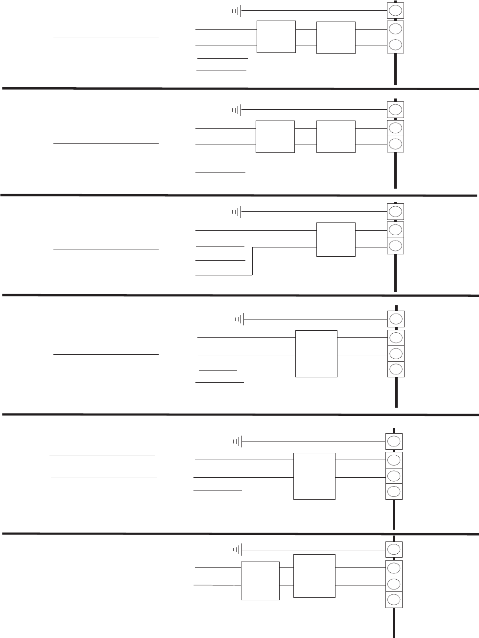
-13-
L1
L2
Ground
Ground Wire Ground
Leg
2 Pole
Terminal
Block
Dedicated
Circuit
Breaker
Or
Disconnect
Note:
- 600V/3 Phase Supply.
Ground
Ground Wire Ground
Leg
2 Pole
Terminal
Block
L3
Neutral
L1
L2
Ground
Ground Wire Ground
Leg
2 Pole
Terminal
Block
L3
Neutral
NOTE: VoltageAt Terminal Block Must Be InAccordance With Spec. Label.
All Wirin
g
To Be InAccordance With Existin
g
NationalAnd Local Electrical Codes.
L1
Ground
Ground Wire
Ground Leg
3 Pole
Terminal
Block
Neutral
PRIMARY
208
-
2
4
0
V
1
phase line voltage wiring to unit
VOLTAGE
(ACTUAL)
E
X
T
I
N
T
E
X
T
I
N
T
E
X
T
I
N
T
E
X
T
I
N
T
Dedicated
Circuit
Breaker
Or
Disconnect
Dedicated
Circuit
Breaker
Or
Disconnect
Dedicated
Circuit
Breaker
Or
Disconnect
(BY OTHERS)
600V/3ph
460V/3ph
208V/3ph
380V/3ph
Step down
Transformer
600V/208V
by others
Step down
Transformer
460V/208V
by others
L1
L2
Neutral
L2
L3
L3
- 600V/1ph between any two hot leg.
- 347V/1ph between hot and neutral.
Note:
- 460V/3 Phase Supply.
- 460V/1ph between any two hot leg.
- 277V/1ph between hot and neutral.
Note:
- 380V/3 Phase Supply.
- 380V/1 phase between two hot legs.
- 220V/1 phase between hot and neutral.
Note:
- 208V/3 Phase Supply.
- 208V/1 phase between two hot legs.
- 120V/1 phase between hot and neutral.
L1
Ground
Ground Wire
Ground Leg
3 Pole
Terminal
Block
Note:
- 120V/ 1 phase Supply.
- 120V/1phase between hot and neutral.
- 240V/1phase between two 120V/1ph supply.
Neutral
E
X
T
I
N
T
Dedicated
Circuit
Breaker
Or
Disconnect
120V/1ph
L2
120V/1ph
L1
Ground
Ground Wire
Ground Leg
3 Pole
Terminal
Block
Note:
- 120V/ 1 phase Supply.
- 120V/1phase between hot and neutral.
- 240V/1phase between two 120V/1ph supply.
Neutral
E
X
T
I
N
T
Dedicated
Circuit
Breaker
Or
Disconnect
120V/1ph Step up
Transformer
120V/240V
min. 2kVa
by others
-14-
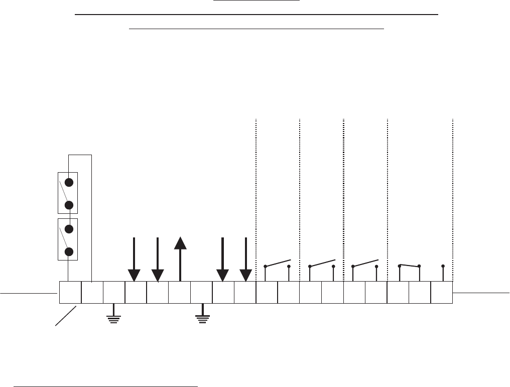
WARNING: Failure to wire the controller in accordance with the wiring diagram that was supplied
with the unit could permanently damage the GSTC/GSP board. Such errors will void the unit warranty.
GS SERIES
EXTERNAL CONTROLS WIRING CONNECTIONS
LOW VOLTAGE TERMINAL STRIP
NOTE: This is a wiring diagram only. For specific wiring instructions, it is necessary to refer
to the wiring diagram which is supplied with each unit.
generic
12346
578910 1211
EXTERNAL
INTERNAL
EXTERNAL
INTERNAL
Security Loop
Modulation Input Signal “A"
Modulation Input Signal “B”
10 Vdc output
Full Tank Blow Down (FTBD)
enable (24 Vac)
Safety Interrupt (24 Vac)
NOTE: If no On/Off Control is used then a field jumper
must be connected across terminals 1 and 2 in order
for the humidifier to operate.
14 1815 16 17
13
COM
COM
COM
COM
N.O.
N.O.
N.O.
N.O.
N.C.
Humidifier “ON”
Humidifier “ACTIVE”
Humidifier “SERVICE”
Humidifier “FAULT”
Low Voltage Terminal Strip
1 & 2: Wire all on/off controls and safeties between these two terminals. If not used, jumper1&2forthe
unit to operate.
4: Modulating input to humidifier “A”.
5: Modulating input to humidifier “B”.
6: 10 Vdc output.
8: When 24 Vac input received, the unit will initialize a full tank blowdown.
9: Safety interrupt (24 Vac).
10 & 11: Remote indication connection for humidifier “on” status indication.
12 & 13: Remote indication connection for humidifier “active” status.
14 & 15: Remote indication connection for service required indication.
16 & 17 & 18: Remote indication connection for fault indication.
++
CONTROL INSTALLATION
·Mount any wall humidistat (control or high limit)
over standard electrical box at height similar to
typical thermostat. Any wall humidistat should be
in location representative of overall space being
humidified and not in path of blower pack or air
supply grille. Do not mount on an outside wall
where temperature fluctuations can affect control
response.
·Mount duct humidistat in location representative
of overall air humidity, usually in return duct. Do
not mount it directly in front of steam distributor or
in turbulent or mixing zone. Mount humidistat
where air's humidity and temperature are uniform
and representative of spaces being humidified.
·Mount duct high limit humidistat downstream of
steam distributors far enough that, under normal
humidity and air flow conditions, steam will have
been fully absorbed (typically at least 10 feet). It
must be located to sense high humidity only
when uniform and representative air is
over-humidified or approaching saturation.
·Mount duct air-proving switch so that it is able to
sense air flow or lack of it. Wire it to make when
air flow is sensed and break when air flow fails.
·Check operation of all on/off controls before
starting humidifier.
·Calibration of controls (on/off or modulation) in
the field may be necessary due to shipping and
handling. Verify humidistat accuracy before
commissioning system.
PLUMBING
NOTE: All water supply and drain line
connections should be installed in accordance with
local plumbing codes.
FILL WATER SUPPLY LINE
·Each unit is supplied with an adapter for the fill
valve (½”NPT ). Fill rate 10 l/min all unit sizes.
Size of piping is a minimum ½” copper,
recommend ¾” up to within 4 feet of unit.
·Standard fill valves are sized for water pressure
ranging from 30 to 80 psig (ideally 55 to 60 psig).
For other pressures, consult factory. This
pressure should be measured at the humidifier if
the water pressure is suspect.
·It is recommended to have a faucet installed
close to the humidifier to allow quick filling of the
system on initial start up. This can also be very
useful for mandatory cleaning of the unit.
·ALWAYS supply and install a shut off valve and
union in the water supply line dedicated to the
humidifier to facilitate servicing.
·If water hammer occurs, install a shock arrester
on the fill water line just before the inlet to the fill
valve. Water hammer will damage the fill valve.
·A 1” air gap is designed into the fill system of the
GS humidifier. Some local plumbing codes may
still require the installation of a double check
valve on the fill line to the humidifier to prevent
contamination of the supply water system. Verify
with local codes and install if necessary.
DRAIN LINE
·The humidifier is equipped with a ¾”O.D.
Unthread ed drain outlet connection on the side
of the humidifier. A vacuum break valve is
installed internal to the unit on the drain line. The
drain water line must be piped to a drain funnel to
provide an air gap before connection to the
building drainage system.
-15-
1/2” NPT Water Supply
(by Nortec)
Union
(by others)
Check Valve
(by others,
if required) Manual Shut-of
f
(by others)
Funnel with
Air Gap (by others)
Union
(by others)
Manual
Shut-off
(by others)
3/4” O.D.
Drain
(Hose clamp by Nortec)
1/2” NPT Female
Auxiliary Drain
Figure # 11
Plumbing Connections
·The drain line should not end in a sink used
frequently by personnel, or where plumbing
codes prohibit it. Route to a floor drain or
equivalent for safety reasons. Internal drain water
tempering will ensure a maximum of 140ºF
(60ºC) exiting water temperature.
·Never install PVC piping as a drain line material.
Always use material suitable for with-standing
140ºF (60ºC).
·Keep drain lines as short as possible. Keep drain
lines sloped down, not level and not up since low
spots in drain lines will accumulate sediment and
cause backup. The drain line should be 1-1.5"
O.D. or larger. Consult local codes.
·When the drain pump is activated, the tank drains
at a rate of 7-8 gal/min (18-20 l/min).
AUX DRAIN PORT
·An auxiliary drain port is also provided on the
side of the humidifier. It can be used to manually
drain the unit, if required. The unit is shipped
with this connection plugged. It is recommended
to install a shut off valve on this line (see Figure
#11).
·The auxiliary drain port is used with the standard
freeze protection. Install a shut off valve on this
line and pipe to the drain funnel (see Figure #11).
The manual shut off valve must always be in the
open position when the unit is operating but can
be closed for servicing of the unit.
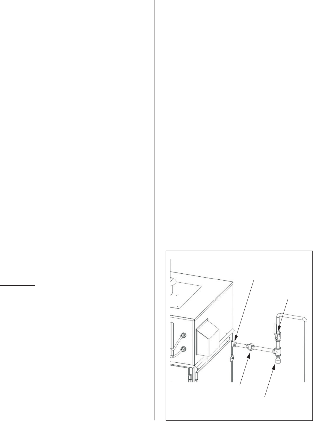
STEAM LINES AND CONDENSATE LINE
·Steam hoses and clamps are provided with the
GS humidifier for connection to the steam lines.
Refer to Figure #12 for connection details.
·For steam line installation between the humidifier
and distribution system, consult the distribution
system installation manual. Steam Distributor
Installation Manual - Form #XX-231 and SAM-e
Short Absorption Manifold - Form #XX-249.
·The GS series of Gas-Steam humidifiers can
develop steam pressures up to 12”w.c. to
overcome duct and steam line pressures. An
enclosed trap on the drain line prevents steam
from going to drain. Duct pressures above 12”
will cause steam to exits through the drain line.
Consult factory.
GS Outdoor Installation
GS Outdoor units are CSA certified for outdoor
installation and come complete with exhaust venting
and internal ventilation (cooling) for the electronics.
Heaters for freeze protection are standard with outdoor
units.
All installations must conform with local building
codes or, in the absence of local codes, with the
National Fuel Gas Code ANSI Z223.1 in the United
States or CAN/CGA B149 Installation codes in
Canada. NORTEC can not accept responsibility for
installation code violations.
MOUNTING
·Typical rooftop installations are shown in Figure
#13 & #14.
·The GS Outdoor unit comes standard with
cutouts in the base to allow for lifting by a forklift.
When lifting by this method, ensure that the forks
extend across the entire base to prevent tipping
or damage to the unit.
·The enclosure also comes complete with four (4)
removable lifting lugs fastened to the base. All
four lugs must be utilized if moving the unit in this
manner. Protect the cabinet from damage from
the lifting cables/chains during lifting. The lifting
lugs should be removed from the base once the
unit has been correctly positioned on the curb
mounting.
·See Figure #15 for clearance details.
-16-
Snap on Insulation
Steam Line
Hose cuffs &
clamps supplied
Figure #12
Steam Line Connection
-17-
BH Vent
(By Nortec) AHU
Insulated
Steam Line
(By others)
Gas Line with
Manual Shut-off
(By others)
Water
Supply
Manual
Shut-off
Drain
Lines
Funnel
With Air Gap
Roof Curb
(By others)
Electrical
Disconnect
(By others)
BH Vent
(By Nortec)
Insulated
Steam Line
(By others)
Gas Line with
Manual
Shut-off
Electrical
Disconnect
(By others)
Roof Curb
(By others)
Figure # 13
GSTC Outdoor Typical Installation Rooftop
Figure # 14
GS Outdoor Typical Installation Rooftop
-18-
FRONT RIGHT
TOP
Left
Minimum Required Clearances
Model Front Left Right Back
GSTC Outdoor 100 30" (76cm) 0 40" (101.6 cm) 6" (15.25 cm)
GSTC Outdoor 200 30" (76cm) 0 40" (101.6 cm) 6" (15.25 cm)
GSTC Outdoor 300 30" (76cm) 30" (76cm) 40" (101.6 cm) 6" (15.25 cm)
GSTC Outdoor 400 30" (76cm) 30" (76cm) 40" (101.6 cm) 6" (15.25 cm)
GSTC Outdoor 500 30" (76cm) 30" (76cm) 40" (101.6 cm) 6" (15.25 cm)
GSTC Outdoor 600 30" (76cm) 30" (76cm) 40" (101.6 cm) 6" (15.25 cm)
Figure # 15
GSTC Outdoor Clearance
Figure # 16
Roof Curb Dimensions
ROOF
PIPE CHASE
ELECTRICAL SIDE
BURNER SIDE
BASE FRAME
ELEMENT
CURB
34 1/8”
(86.6cm)
A
3 3/4”
(9.5cm) MAX.
11/16”
(1.8cm)
6.0”
(15.24cm)
5.0”
(12.7cm)
AA
Roof Curb
by Others
Pipe
Chase
Lifting
Hooks
SECTION A-A
3/4”
(1.90cm)
Roof Curb Dimensions
Model Dimension A Curb Height Shipping Weight Operating Weight
GSTC Outdoor 100 8.63" (27.91cm) 15" (38.1cm) Min. 400 lbs (181 kg) 556 lbs (252 kg)
GSTC Outdoor 200 15.06" (38.25cm) 15" (38.1cm) Min. 500 lbs (227 kg) 744 lbs (338 kg)
GSTC Outdoor 300 30.63" (77.8cm) 15" (38.1cm) Min. 700 lbs (318 kg) 1185 lbs (539 kg)
GSTC Outdoor 400 30.63" (77.8cm) 15" (38.1cm) Min. 745 lbs (339 kg) 1210 lbs (550 kg)
GSTC Outdoor 500 46.25" (117.5cm) 15" (38.1cm) Min. 800 lbs (363 kg) 1505 lbs (684 kg)
GSTC Outdoor 600 46.25" (117.5cm) 15" (38.1cm) Min. 844 lbs (384 kg) 1525 lbs (693 kg)
·The integral base of the GS Outdoor model is
designed to mount on a curb. The curb must be
built to structurally support the entire weight of
the humidifier when in operation. Required curb
dimensions are given in Figure #16 .
·Ensure that the humidifier is mounted level.
·The pan in the bottom of all outdoor models has
a pipe chase for routing of services into the
humidifier from below.
·It is not necessary to make the hole in the roof
the same size as the curb. The curb drawing
shows the location and size of the pipe chase
required. The pipe chase should be sealed when
the installation is complete to ensure positive or
negative pressure from the building.
·The panels of the outdoor model have louvers to
provide ventilation for the electronics and air for
the combustion process. Locate the unit so that
louvered panels are a minimum of 10 ft from any
mechanical exhaust outlet.
·When mounted on the curb, the lowest air intake
louvers must be a minimum of 12” above any
surface where snow or ice could accumulate. In
areas where normal snow accumulation is
higher, mount the unit accordingly.
·Do not store or use gasoline or other flammable
vapors and liquids in the vicinity of the humidifier.
·The humidifier may be installed directly on
combustible flooring or, in the U.S., on wood
flooring or Class A, Class B or Class C roof
covering materials.
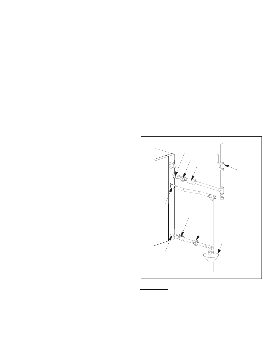
GAS PIPING
·Installation of piping must be in accordance with
local codes, and the National Fuel Gas Code
ANSI Z223.1 in the United States or
CAN/CGA-B149 Installation Codes in Canada.
·Refer to the indoor gas piping installation
guidelines for gas line sizes, pressures, leak
testing procedures, and safety instructions.
·Gas lines are to be routed to the outside
connection on the right side near the back of the
unit. The installation of a sediment trap and a
certified manual shut-off valve are required
outside of the unit. The gas piping must not block
access to or prevent opening of the right side
service door. Refer to Figure #17 for details.
·Nortec recommends that each Gas Fired
Humidifier has it’s own regulator installed in line to
the unit. Th operating Natural Gas pressure
supplied for the GS units must be in the range of
5-9 “ of Water Column and propane version
10-14” of Water Column.
·Over pressure protection devices shall be
provided to prevent the pressure in the piping
system from exceeding that value that would
cause unsafe operation of any connected and
properly adjusted Gas utilization equipment. See
Figure #18
·If the system has a pressure that is higher than
the max working pressure of our humidifier, then
an Over pressure protection system is required. If
there is an Over pressure protection device
installed, it MUST consist of 2 devices in series.
(A pressure regulator plus one other device) Both
these devices must be able to work on their own
without damaging any downstream piping or
appliance, and the only way the downstream
-19-
Inlet coupling supplied
Shut-off Gas Valv
e
(by others)
Union
(by others)
Sediment Trap
(by others)
Figure #17
Gas Piping
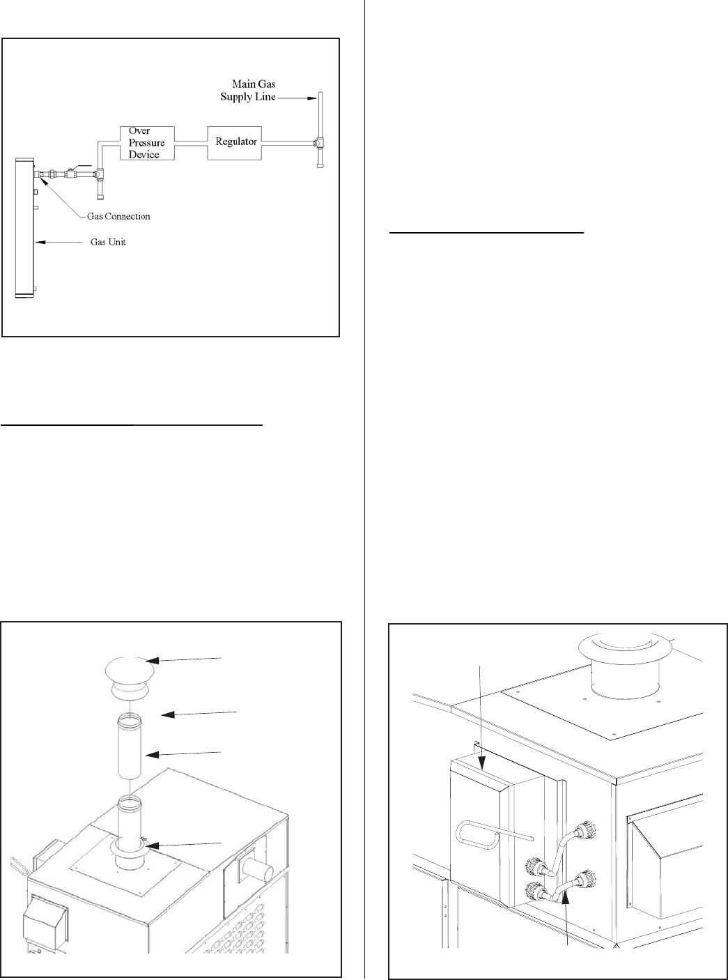
system can be damaged is by the failure of both
devices.
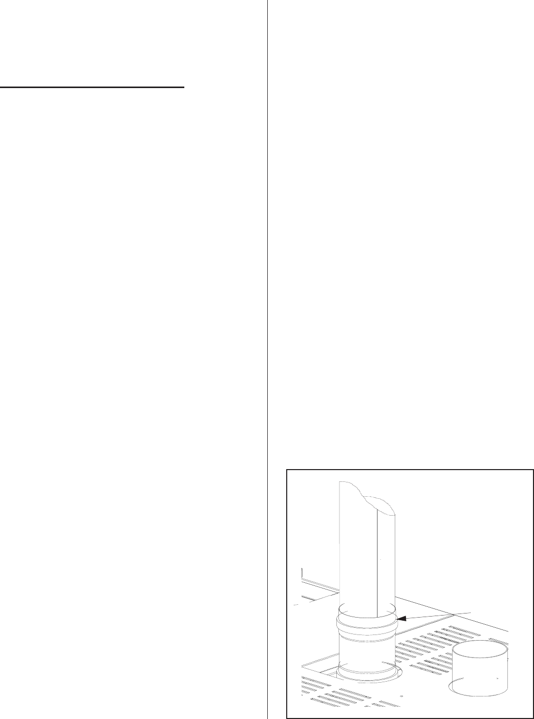
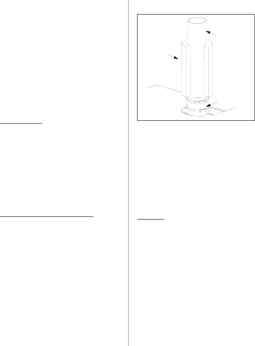
EXHAUST VENTING - OUTDOOR UNITS
·All required exhaust venting is provided with each
GS Outdoor model, by Nortec, including rain cap
and storm collar. All venting components
external to the unit are shipped with the unit and
must be installed on site. Refer to Figure #19 for
venting components.
·Each vent length and the rain cap have a built-in
mechanical locking band and gasket. Simply
push together each component to the stop bead,
which provides an air & water-tight seal. Then
tighten the integrated locking band on each
component to complete the installation of the
exhaust venting.
·The rain cap must extend at least 2 feet above
any ridge within 10 feet of the unit. The exhaust
venting can be extended using additional vent
lengths purchased from Nortec.
ELECTRICAL INSTALLATION
·Power and control wiring is to be routed into the
humidifier through the pipe chase in the base pan
of the outdoor models located in the burner area.
·Installation details for primary and low voltage
control wiring are the same as for indoor units.
·A field supplied NEMA rated weatherproof
disconnect switch must be mounted external to
the GS Outdoor unit to allow for power
interruption during servicing and/or maintenance.
A mounting plate, located on the front of each
outdoor model above the electrical access door,
is available for mounting of the disconnect switch.
Two electrical conduits are provided for routing
the primary wiring to the disconnect switch and
then back inside the enclosure to the main power
terminal strip. See Figure #20 for details.
-20-
Disconnect box
(By others)
Primary wiring
(
B
y
others
)
Figure #20
Electrical Box
All Venting provide
d
by Nortec
Rain Cap
Extension Pipe
Storm Collar
Figure #19
Exhaust - Outdoor Units
Figure #18
GasPiping
FILL WATER SUPPLY LINE
·Each unit is supplied with a ½” NPT male
connection to the fill valve. Refer to Figure #21
for connection details. A minimum fill rate of 10
l/min (2.6 gal/min) is required for all unit sizes.
Allowable pressure range is 30-80 psig.
·Always install a manual shut off within the
building to allow isolation of the water to the unit.
A union must be installed on the fill line prior to
the fill valve to allow for servicing.
·Heat trace fill line piping above rooftop from the
pipe chase up to the fill valve.
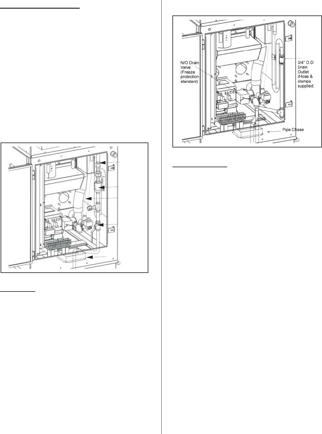
DRAIN LINE
·GS Outdoor units have an integrated 12”w.c. trap
and vacuum break valve on the drain line. A
drain hose, connected to the outlet of the internal
trap, terminates at the pipe chase in the burner
section.
·Route the drain hose to a drain funnel in the
building to provide an air gap before entering
main building drain/sewage system.
·When the drain pump is activated, the tank drains
at a rate of 18-20 l/min (7-8 gal/min).
·Internal drain water tempering will ensure a
maximum of 140°F (60°C) during normal
operation.
AUXILIARY DRAIN
·Standard GS Outdoor units come with a capped
¾”NPT auxiliary drain connection at the bottom of
the tank. It is recommended to install a manual
shut-off valve on this connection and route to
drain (provide an air gap).
·GS Outdoor units standard with freeze protection
have a normally open drain valve mounted at the
auxiliary drain connection and piping that
terminates at the pipe chase in the base pan.
This valve opens and will drain the contents of
the tank in the event of a power failure. See
Figure #22. Install a manual shut off valve on this
line and pipe to the drain funnel. This valve must
always be left in the open position when in
operation but can be closed for servicing of the
unit.
·Drain pipe should be capable of withstanding
200°F temperatures.
-21-
Figure #22
Drain Connection
1/2” NPT
Connection
Check Valve
(If required)
Manual
Shut-Off
Valve
(By others)
Pipe Chase
Drain Line
Connection
Figure #21
Fill Water Connection
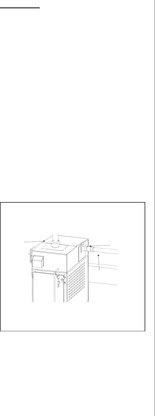
STEAM LINES
·The steam outlet connection is located at the
back of the GS Outdoor unit. Steam hose(s) and
clamps are supplied with the unit and are
intended to provide a flexible coupling outside of
the unit to the building steam lines. See Figure
#23.
·GS Outdoor models can develop steam
pressures up to 12”w.c. to overcome duct and
steam line pressures. Pressures above 12”w.c.
will cause steam to exit through the drain line.
·Steam lines can be routed to an air handler on
the roof or pipe chased (external to the unit)
through the rooftop to enter the building.
·All steam lines must be insulated to reduce
losses.
·For steam line installation guidelines, consult the
distribution system installation manual (Steam
Distributor Installation Manual Form #XX-231 and
SAM-e Short Absorption Manifold Form
#XX-249).
PRINCIPLES OF OPERATION
Combustion
The combustion system is based on a fully
modulating forced draft combustion air blower(s), a
negative pressure regulated gas valve, and a 100%
premix burner. On a call for humidity, the combustion
air blower(s) starts and creates a negative pressure(s)
across an orifice located at the air inlet. The blower is
energized to purge the system, then the hot surface
ignitor is activated. During this time the electronic
ignition module does a diagnostic check of safety
systems including the air proving switch which senses
the negative pressure at the air inlet orifice. After the
function of the safety systems has been verified, the
gas valve(s) will open and the gas/air mixture is ignited
by the hot surface ignitor. If a flame is sensed by the
flame sensor, the gas valve(s) remains open and
combustion continues. If a flame is not sensed, the
above sequence is repeated to a maximum of three
times after which the ignition module will lock out. The
gas valve(s) maintains a constant ratio air to gas
independent of blower speed or external conditions.
This air and fuel is thoroughly mixed in the blower(s)
and then forced through the burner ports where
ignition occurs.
Hot products of combustion are forced through a
baffle inside the heat exchanger and then vented
outside. The heat exchanger has a large flat surface
to minimize scale build-up and promote scale
shedding to the bottom of the tank. This self-cleaning
action helps to maintain the efficiency of the heat
exchanger while the smooth surfaces allow for easy
cleaning when necessary.
The GS 100 has a single removable combustion
chamber/heat exchanger. The combustion system is
duplicated on larger units with multiple chambers
inside a common tank.
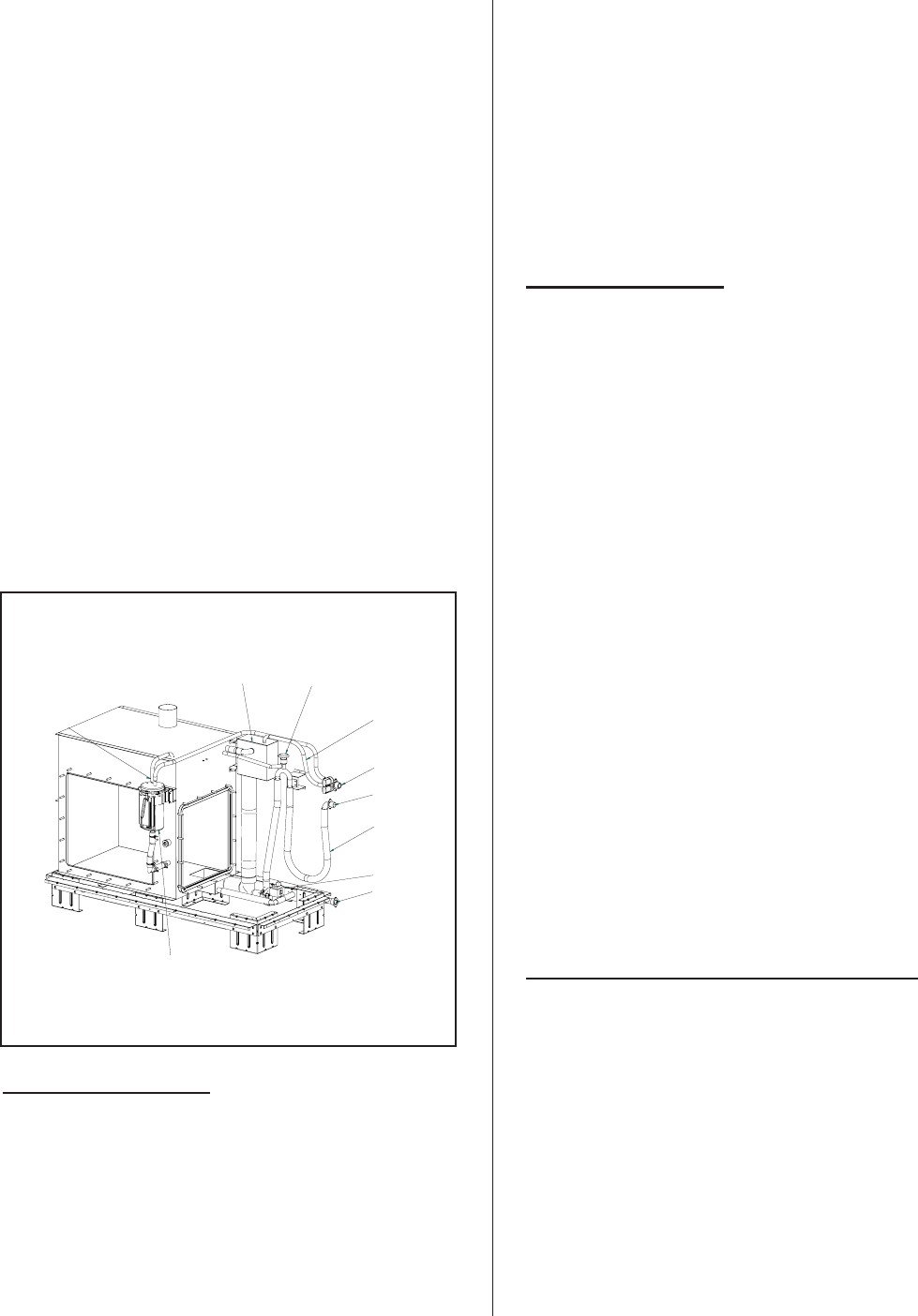
WATER MANAGEMENT
The GS Series of humidifiers is equipped with a
unique float chamber water level monitoring device.
Two magnetic floats (one is a backup) measure 5
different water levels in the humidifier for proper
operation. The float chamber and board are located
away from the boiling action to increase reading
accuracy and reduce mineral build-up since it is not in
the boiling water. The float chamber is connected to
the tank under the water level and above the water
level to ensure equalization of pressure between the
tank and float chamber. In addition, cooling water is
introduced in the float chamber to reduce scale
build-up. The unit also includes an internal 1” air gap
and a vacuum breaker to prevent siphoning effect.
-22-
Cuff hose and
clamps provide
d
Steam line
(Insulation
recommended)
BH Venting
Supplied
Figure #23
Steam Connection
On initial start-up, the solenoid operated fill valve
fills the tank. The water level reaches the backup float
first and then the main float. If the backup and main
floats do not read the same water level during the
operation of the unit, the unit will shut down on a fault.
The unit will continue to fill the unit to the top green
position. The drain pump will then be energized to
drain the water level down to just below the bottom red
position and then the fill valve will energize again to fill
the unit to the middle yellow position. During this time
the software is performing a test on the fill valve and
drain pump.
If a demand signal is present, the unit will then
begin the combustion sequence. As the unit operates,
the fill valve with be pulsed to maintain the water level
between the yellow and green positions. During steam
production the unit will also check if the floats and
drain pump are operational by activating a drain
sequence every 24 hours. (adjustable to time of day)
START UP PROCEDURE
START-UP CHECKLIST
Before the GS humidifier is operated for the first
time, a complete inspection must be performed to
ensure that the installation and all water, gas, steam,
electrical and venting connections to the humidifier
conform to the guidelines in this manual. Complete
the checklist on pages 25 & 26 before commissioning
the unit.
Qualified personnel must correct any deficiencies
with the installation before commissioning takes place.
Prior to starting the humidifier, it is necessary to
ensure that no dirt or dust has accumulated in the
electronics compartment or the burner area. A build
up of dust on the electronics can cause overheating
and early failure of the components. If necessary,
clean the area around thehumidifier to prevent
contaminants from being drawn into the combustion
blowers.
FILLING THE SYSTEM
Before the GS unit will initiate combustion it must
be filled with water and the internal controller must
have completed a self-test to verify that the water fill
system, level controller, and drain pump are
functioning correctly.
·Close the shut-off valve in the gas supply line
·Remove any demand signal to the unit
·Open the shut-off valve in the water supply line
·Switch the humidifier on
·The fill valve will energize and the tank will begin
to fill (fill time is approximately 10 to 30 minutes
depending on unit size). Once the float chamber
has registered low water level, the unit will
perform an internal test of the fill and drain
system as described in the Water Management
section
·At the completion of the test, the float chamber
will indicate middle float position (green LED) and
the unit will go into standby mode until a demand
signal is received
·Proceed to the safety shut-off test
TESTING THE IGNITION SAFETY SHUT-OFF
Test the ignition system safety shut-off in the
following method.
·Close the shut-off valve in the gas supply line
·Set the demand signal to the humidifier to 100%
·Ensure all external controls connected to the
security loop are closed
·Switch the humidifier on
-23-
Float Chamber
Presure Equalizer
Aux. Drain
Drain Pump
Dual Fill Valve
Drain Outlet
Vacuum Break
Fill Chamber
Main Fill to System
Internal Trap
Figure #24
Plumbing Connections

·At the completion of the float test, the humidifier
will begin the combustion sequence by energizing
the combustion blowers
·All blowers will run at full output for 30 seconds to
pre-purge the combustion chamber. During this
time the controller will monitor that all air proving
switches closed to prove air flow
·The igniter(s) will be energized for 15 seconds,
allowing it time to heat to the appropriate ignition
temperature and the gas valve will be energized
·After 4 seconds both the gas valve(s) and the
igniter will be de-energized
·After three trials for ignition (complete with
pre-purge) the red LED on the ignition control
module will begin blinking to indicate a safety
lockout and a fault message will be displayed on
the humidifier display
·NOTE: On multiple burner models, each burner
tries to ignite in sequence. It is necessary to wait
for all burners to cycle to complete the test.
·Manually re-open the gas supply to the
humidifier. No gas should flow to the burner(s)
·To reset the humidifier, shut off the power switch,
then turn the power back on
STARTING THE HUMIDIFIER
Once the tank has been filled and the ignition
safety test has been performed as outlined above, the
humidifier is ready to be put into operation.
·Verify that the inspection checklist has been
completed and all deficiencies with the
installation have been corrected
·Open the shut-off valve in the gas supply line
·Open the shut-off valve in the water supply line
·Ensure all external controls connected to the
security loop are closed
·Verify that the building demand signal is
connected to the humidifier
·Install and secure all cabinet service doors
·Switch the humidifier on
·At the completion of the float test, the humidifier
will begin the combustion sequence and each
burner will ignite in sequence
·Depending on the system demand the
combustion blowers will modulate faster or slower
to control the burner input
·The water in the tank will heat up and begin to
boil, delivering steam to the distribution system
·During the boiling sequence the water fill valve
will periodically activate to replenish water that
has evaporated from the tank
·Once the humidity requirements have been
satisfied (demand drops below minimum %) all
gas valves will be de-energized and the blowers
will be shut off after performing a post purge of
the combustion chamber
·The humidifier will go into standby mode until the
next call for humidity (demand rises above
minimum %) at which time the unit will again
begin the combustion sequence
TAKING OUT OF OPERATION
If it is required that the humidifier be taken out of
operation (e.g. for service or end of season
shut-down), proceed as follows:
·If the unit is firing, remove the demand signal or
open the security loop, allowing the burners to
shut off and the blowers to perform a post purge
of the heat exchangers before shutting off
·Switch the main power switch from On to Off and
then to the Drain position. The drain pump will be
energized and the tank will begin to drain
·Once the tank has completely emptied shut off
the drain switch
·Close the shut-off valve in the gas supply line
-24-

-25-
GS INSPECTION CHECK LIST
HUMIDIFIER MOUNTING
£Verify proper clearances around the unit
£Humidifier mounted level
£Humidifier properly secured to stand and stand bolted to floor
£All service doors accessible
£Roof curb sized correctly (Outdoor Model Only)
GAS PIPING
£Correct gas line size installed
£Certified manual shut off valve and union installed
£Sediment trap installed
£Gas piping leak tested
£Air purged from lines
£Proper gas supply pressure
£Regulator dedicated for each gas unit
EXHAUST GAS VENTING
£Comply with local regulations
£Proper venting materials used (B or BH) – refer to gas codes
£Maximum vent length of 100 feet (70 feet for direct vent models)
£Proper pipe diameter used
£Condensate tee installed
STEAM LINES
£Slope up 2” per 12”
£Sloped back to drain
£Slope down ½” per 12”
£Trapped 2” more than static duct pressure
£Traps Size _______
£Insulated
£Length/Size ____________
£90 deg. Elbows qty: ____
£45 deg. Elbows qty: ____
£Can condensate be trapped anywhere in the steam line? yes £no £
CONDENSATE LINES
£Sloped back to drain
£Trap is greater than 2” duct static pressure
£Size of trap_______
-26-
SUPPLY WATER LINE
£Nortec supplied adapter installed on fill valve (½”NPT)
£Manual shut off valve and union installed
£Verified pressure (30 – 80 psig)
£Water source of 10 l/min (2.6 gpm)
£Leak tested
£½” dia. At max 4ft of the unit
DRAIN LINES
£Air gap located within 3ft of the unit
£Minimum drain line size of 1” in dia.
£Downward slope
£Tundish (funnel) installed to provide air gap
£Temperature rating of piping
£Hose connections tightened
£Auxiliary drain piped with shut off valve to tundish
WATER QUALITY
-Well water £-City water £-Softened water £-RO/DI water £
Conductivity:_______mhmos Hardness: _______GPG Silica____ppm Chlorides:_______ppm
pH:_______
NOTE: Failure due to chloride corrosion is not covred under Nortec’s standard warranty. Consult
factory for more information.
ELECTRICAL INSTALLATION
£Comply with local regulations
£Proper supply voltage (must match rating plate) and breaker size
£Electrical disconnect switch close to humidifier
£Cables properly affixed
£Low voltage wiring & control signal(s) wired to correct terminals
£Humidifier configured for correct control signal(s)
TYPE OF CONTROLS INSTALLED/ LOCATION/ WIRING/ SETTING
£High Limit ______________________________
£Air Proving _____________________________
£Modulation Control________________________
£On/Off Control ___________________________
£Controls by Nortec________________________
£Controls by Others________________________
·Close the shut-off valve in the water supply line
·Isolate the humidifier from the electrical power
supply at the main disconnect switch
SCALE MANAGEMENT
The gas humidifier will periodically “blowdown”
water from the tank to reduce the concentration of total
dissolved solids that accumulate during long term
operation. Gas Humidifiers are shipped factory set
with a blowdown of 25%. This setting ensures that
scale build-up will be minimized for all water
conditions.
Once the water conditions are known, the
blowdown rate can be adjusted by software (GSTC
models) or by using dip switches on the logic control
board (GSP models).
Another effective means of controlling the amount
of scale in the tank is with the use of the Full Tank
Blowdown (FTBD) built into the software. When this
feature is activated, the drain pump will be energized
to drain the entire contents of the tank and then the
tank will be refilled with fresh water, thus keeping the
amount of total dissolved solids to a minimum. The
feature can be programmed in the software to occur
after a specific amount of operating time and can also
be triggered by a signal sent to the humidifier from a
building management system.
WATER QUALITY
Due to the wide range of water conditions found
throughout North America it is important that the
blowdown is set according to the local water
conditions. By water conditions we are referring to the
hardness of the water supplied to the humidifier. The
hardness is measured in grains per gallon. It is also
important to test for silica content. Silicates may cause
foaming and contribute to scale buildup in the
humidifier tank and float chamber.
If you are unaware of the hardness or silica
content of your water supply, there are many “do it
yourself” kits which can be purchased, or there are
several companies that will perform the tests for a
reasonable price. You can even contact your
municipality for your water condition or order the
NORTEC water test kit.
Note: Water quality conditions resulting in
component failures are not covered under NORTEC’s
standard warranty.
·Silica Test: Measured in ppm (parts per million)
Follow the directions with the kit. A high reading
will decrease the performance of your system.
The recommended operating range for silica is 0
ppm to 14 ppm. Note: A high silica content along
with a high hardness content may increase the
service intervals of the system . Consult the
factory if this condition exists at the site.
·Hardness: Measured in gpg (grains per gallon).
Follow the instructions on each individually
wrapped test strip and use the colour chart
provided. The recommended operating range for
hardness is 0 gpg to 12 gpg. Note: High
hardness along with high silica may increase the
service intervals of the system. Consult the
factory if this condition exists at the site.
·pH: Follow the directions on the test strip bottle.
The recommended operating range for pH is 6.5
to 7.5 on the colour scale. Consult the factory if
outside these parameters.
·Chlorides: Measured in ppm (parts per million).
Follow the directions on the test strip bottle. The
recommended level for chlorides is not to exceed
25 ppm.
NOTE: Failure due to chloride corrosion
is not covred under Nortec’s standard warranty.
Consult factory for more information.
·High levels of chlorides will attack stainless steel.
Consult the factory for additional information if
your water contain high levels of chlorides.
-27-
Figure #25
Site Water Test Kit P/N 1507214
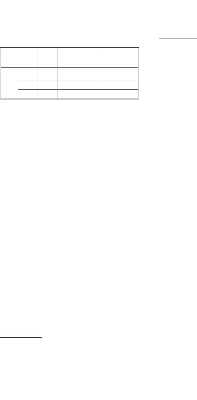
·Conductivity: Measured in micromhos. Follow
the directions for the conductivity pen found
inside the box. Multiply the digital reading by 1.5.
The recommended operating range for
conductivity is 0 - 1500 micromhos. Consult the
factory is you measure outside these parameters.
Tech-
nology
Water
Type
Water
Cond.
Range
Hard-
ness
Range
Silica
Range Alkalin.
Range Chlor.
Range
Gas-
Fired Microm
hos GPG PPM pH PPM
Potable 0-1500 0-12 0-14 6.5-7.5 0-25
Treated 0-100 0-1 0-1 7-7.5 0-25
·NORTEC recommends performing a semi-annual
water analysis to ensure optimal performance.
·The humidifier is intended to operate on cold
potable tap water.
·DO NOT use a hot water source to supply the
humidifier. Minerals will adhere more easily to
surfaces and the fill valve's small flow regulating
orifice could become plugged.
·Consider using a water softener. Longer
operating times between tank cleaning will be
reached on softened water.
·Reverse osmosis (RO) water can provide very
long times before cleaning is required since it is
cleaner than softened water. Deionized (DI)
water may be used with all models. Consult your
NORTEC representative for quote on a water
treatment system.
SAFETY INSTRUCTIONS
Refer to front cover and page 1 of this guide.
FAULT CONDITIONS
This appliance is equipped with a self diagnostic
ignition module which identifies a fault code when it
occurs. Refer to the fault & warning list on pg 60.
GSTC MODELS
Faults are indicated with a fault message on the
display of GSTC models. Recovery from lockout
requires resetting of the humidifier. This can be
achieved by momentarily shutting off the power switch
then turning it back on, or by pressing the reset button
on the logic control board mounted inside the electrical
cabinet.
A history of all faults is stored in memory of
the software and can be viewed through the service
level on the display. Refer to the keypad display menu
structure at the end of the manual.
GSP MODELS
Faults are indicated on GSP models with a fault
code on the small display screen attached to the logic
control board. The display can be viewed by removing
the front electrical door. Check the display for the fault
code before shutting off power to the unit. Resetting
the humidifier clears the fault. This can be achieved
by shutting off the power switch, then turning it back
on, or by pressing the reset button on the logic control
board. A list of all fault codes and the type of fault they
represent is located near the back of the manual.
MAINTENANCE
To ensure proper performance and long operating
life of the GS humidifier, it is recommended that the
appliance and installation be inspected at least once a
year by a qualified service person. A proper
maintenance schedule should be followed. Since the
amount and type of maintenance required is generally
as a result of how much the humidifier operates, all GS
humidifiers monitor the amount of steam produced
over time and will indicate when service is required.
All units come factory set with a service interval of 500
hours. This service interval can be adjusted through
software (GSTC models) or by dip switch settings
(GSP models) on the logic control board.
All maintenance work must be performed by
experienced and trained personnel.
Periodic cleaning of the screens in the vent
terminal (where applicable) is recommended.
NOTE Use only NORTEC original parts to
replace damaged or defective components. Failure to
do so may cause improper operation of the humidifier
and will void warranty.
DRAINING THE TANK
·During extended periods of inactivity such as off
season or periods of very low demand, it is
advisable to drain the water from the tank. On all
models this is accomplished by switching the unit
to “Drain”.
·Do not remove the front clean out port on the
tank until the unit has completely drained. On GS
300-600 units do not remove the top clean out
ports on the tank unless the water has cooled or
the unit has completely drained.
-28-
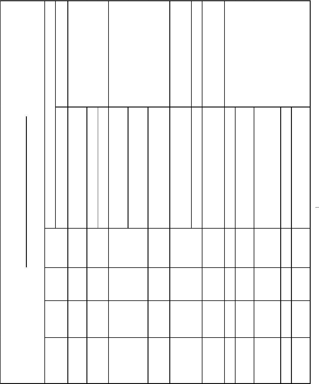
REGULAR MAINTENANCE PREVENTIVE MAINTENANCE
Hot Surface
Ignitor X - Check for continuity.
- Check that Flame Sensor is straight.
- Clean sensor with fine steel wool.
- Remove from the unit and clean with compressed
air from outside matting.
NOTE: It is recommended to replace the burner
gasket each time a burner is removed.
Drain Lines X - Switch to drain and make sure water flows freely.
- Adjust blow down time when required. Check that
scale has not accumulated above 2".
- Drill out tank nipples when required to
ensure nipples are not blocked with scale.
- Clean tank when required. - Clean tank.
Float Chamber X X X - Ensure floats move freely. - Clean scale from float chamber and hose
connecting to hit.
Fill Lines X X X - Inspect for leaks.
Drain Lines XX X
- Inspect for leaks at the drain pump, fill cup and
float chamber.
Gas Venting XX X
- Inspect for leaks. Ensure terminal cap is clear and
any condensation produced flows to condensate
traps. Flue temp should be between 350-400ºF.
Direct Vent X X - Inspect for leaks. Ensure intake terminal is clear.
H/L Stack Sensor XX X
- Visual check that sensor is intact, wired and
attached to the exhaust.
- Replace hot surface ignitor and flame
sensor with replacement kit.
MANDATORY M AINT ENANCE SCHEDULE
WHAT NEEDS TO BE DONE?
Flame Sensor
XX
X
XTank
END OF
SEASON
MID
30 DAYS
after initial
start-up
PARTS
X
Gas Burner
-29-
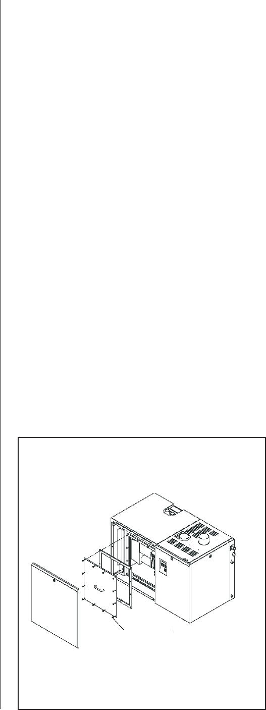
·Ensure that power is switched on again during
periods of demand.
·The GSTC model of the Gas Steam humidifier
includes a pre-cleaning sequence feature. When
activated (through the keypad), the unit will flush
the humidifier, refill with cold water, and flush
again reducing the scale accumulated at the
bottom of the tank.
CLEANING THE STEEL TANK
CAUTION: Water and scale may be hot enough
to cause burns. Turn off humidifier and allow it to cool
before cleaning.
It is recommended that the tank be cleaned at
least once every season to maintain optimum
operation. It may be necessary to increase the
frequency of cleaning or increase the blowdown
setting in areas of hard water or prolonged annual
usage (see the Blowdown Setting section of this
manual).
Cleaning of the humidifier is mandatory and must
be performed on a regular basis.
To reduce cleaning time, use the pre-cleaning
sequence on the GSTC model to help evacuate
mineral debris from the unit. Check the controller
operation to activate this feature.
The combustion chamber walls are usually self
cleaning. The mineral buildup flakes off, due to the
expansion and contraction and violent boiling action
during on/off cycles, and settles to the bottom of the
tank. The combustion end block will have scale build
up, as will the heat transfer tubes. These surfaces
must be cleaned at regular intervals.
Frontal port cleaning will be done through the front
door of the unit. Remove cabinet door on the left of
the LCD display using a Philips screwdriver. Remove
the side tank port opening, by removing the3/16nuts
(½” key or socket is needed).
Additional clean out ports are available on the top
of the 300/400 and 500/600 lb/h tanks. To access
these ports, remove the top cabinet panel using a
Phillips screwdriver. Remove the top clean out ports
my removing the nuts.
Removal of the heat exchanger(s) is not
necessary to clean the inside of the tank.
Scoop out loose scale with a small shovel such as
those used for gardening. Once loose scale is
removed, use a scraper such as a plastic windshield
scraper to remove scale adhering to the tank or heat
exchanger walls. DO NOT use a metal scraper that
will scratch the stainless steel surfaces of the tank.
Once all large pieces of scale have been removed,
vacuum the tank out with a shop vacuum, fill part way
with water, and flush remaining sediment from the tank
through the drain.
Due to the presence of polymer gaskets around
the heat exchanger, do not use any harsh cleaning
chemicals. Please consult NORTEC prior to using any
chemicals. Once the lid has been replaced, fill the unit
with water and examine for leaks.
Inspect the drain and fill lines assembly for scale
build-up and if necessary remove them from the
humidifier for cleaning. If the blowdown assembly
becomes blocked, scale build-up in the tank will be
accelerated and damage to the humidifier could result.
The drain pump may be opened and cleaned. Consult
NORTEC for proper procedure.
Reassemble the drain and blowdown if they were
removed. Re-install tank top and side lids making sure
tank cover gasket is intact. Do not over tighten hold
down nuts. If using a torque wrench do not exceed
50 in/lb (5ft/lb). Re-seal all cabinet lids.
Cleaning the float chamber is accomplished by
removing the hold down screws to access the floats
and using a small brush to gently clean the scale from
the floats and chamber. Ensure that floats are back in
place and o-ring is properly seated before tightening
screws on float chamber. Special attention must be
used when removing or re-installing the float chamber.
-30-
Torque: 50 in-LB (5.7 NM)
Figure #26
Cleaning Tank Access

The switch board must be replaced into the same
position as before cleaning and the tie -wrap must be
used to hold the float chamber in position.
SERVICING THE UNIT
Caution: Disconnect power before servicing this
appliance.
Caution: Label all wires prior to disconnection
when servicing controls. Wiring errors can cause
improper and dangerous operation.
The combustion chamber, heat exchanger and
flue baffles are all fabricated from stainless steel and
do not require internal cleaning.
Should the main burner fail to light, or flame is not
detected during the first trial for ignition period, the gas
valve is de-energized and the control goes through an
interpurge delay before another ignition attempt. The
control will attempt two additional ignition trials before
going into lockout. The valve relay will be
de-energized immediately, and the combustion blower
will be turned off.
SERVICE CHECKS
COMBUSTION BLOWER
The combustion air blower motors are
permanently lubricated and do not require lubrication.
Clean out any dust that has accumulated in the blower
housing using an air gun.
BURNER
The burners are made of ceramic fabric material
and operate in the infrared mode. Depending on the
environment, the burner(s) may require removal of lint
or grease-laden dust periodically. This may be
achieved by removing the burner and applying
pressurized air to the external surface of the material.
Refer to the Servicing Section related to burner
removal.
Flame Sensor
Flame current is the current which passes through
the flame from the sensor to ground. The ignition
module must detect a minimum flame current of 0.7
microamps or a flame proving lockout will occur. To
measure flame current, connect an DC micrometer to
the FC- FC+ terminals on the module. Meter should
read 0.7 uA or higher. If meter reads below “0” on
scale, meter leads are reversed. Disconnect power
and reconnect meter leads for proper polarity.
NOTE: Proper polarity of supply voltage to the
unit is necessary for flame sensing to occur. Oxidation
on flame sensing rod can reduce measured current.
The oxidation can be cleaned from the sensing rod
using steel wool or an emery cloth.
Igniter Check
If the igniter is suspected of being defective then
the following test may be carried out;
1. Ensure that the power and gas is switched off
before servicing.
2. To test the igniter, disconnect the igniter leads
from their terminal connections.
3. Using a multimeter set the Ohm’s scale and
place one of the meter leads on one of the
igniter wire ends and the other meter lead on
the end of the other igniter wire.
Gas Valve Setting
The gas valves used in the GS series humidifier
are negative-pressure-regulated valves. The valve
setting listed on the product rating plate is shown
relative to atmosphere – this setting will always remain
constant.
The valves come preset from the factory for the
correct gas type. If an adjustment is required, use the
following steps:
1. Remove the screw from the pressure port
marked “out” on the back side of the gas
valve.
2. Connect a hose from a digital manometer (or
an inclined manometer capable of reading
below 0.1”w.c.) to the “out” pressure port.
3. Activate the humidifier and measure the gas
valve pressure once the valve is energized
and a flame is established in the combustion
chamber. Verify this pressure to the pressure
listed on the unit specification label.
4. If the pressure needs adjusting, remove the
locking cap on the top of the gas valve.
5. Below the locking cap is an adjustment screw.
Increase the pressure by turning the
adjustment screw clockwise, decrease by
turning counter-clockwise.
NOTE: The pressure will fluctuate slightly as
the unit operates, especially with very
sensitive measuring devices. Use the mean
pressure value as the set pressure.
-31-
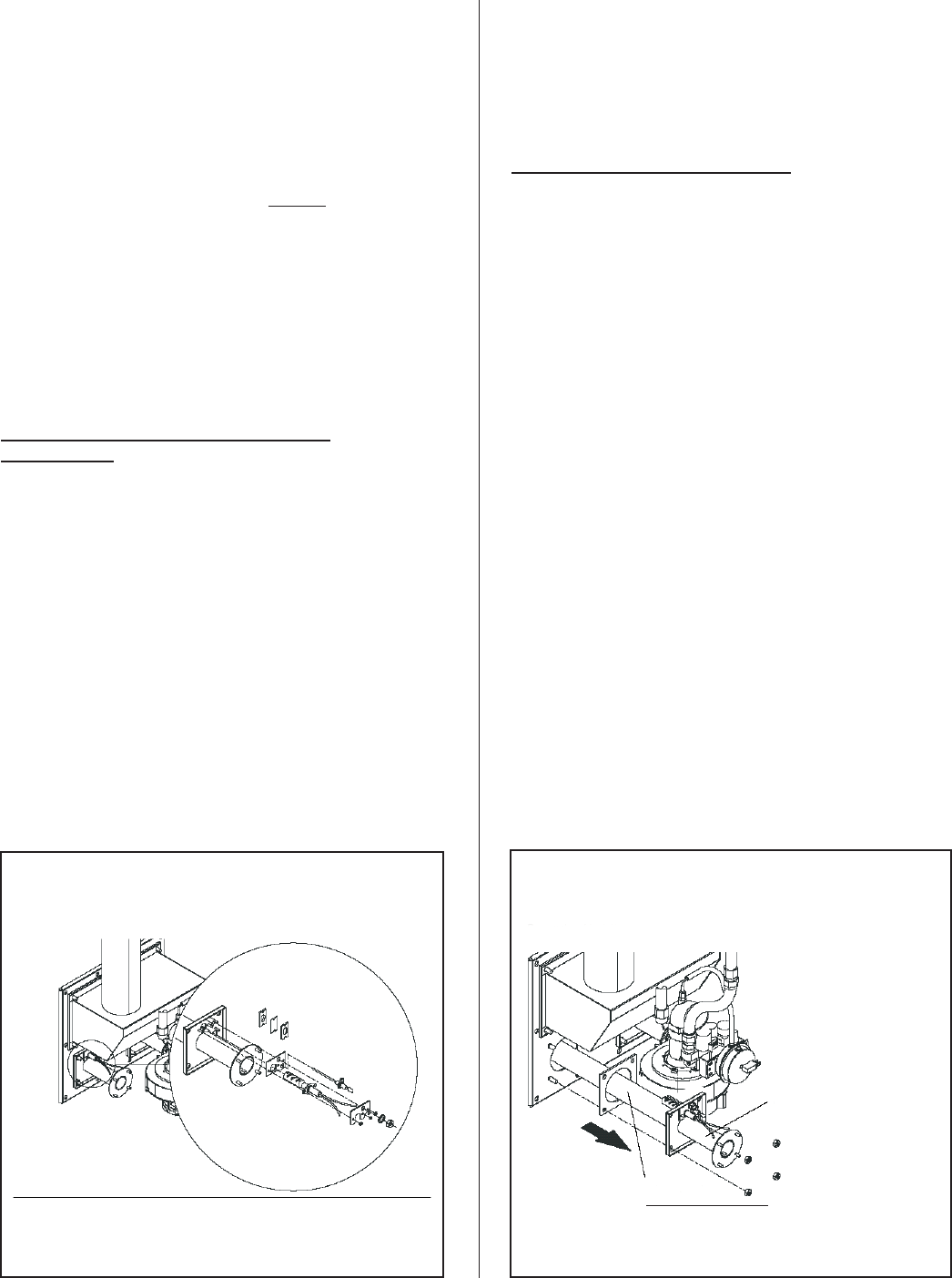
6. Once the pressure has been adjusted, replace
the locking cap.
7. Replace the screw in the “out” pressure port
and tighten firmly.
COMPONENT REPLACEMENT
CONSULT FACTORY PRIOR TO THE
REPLACEMENT OF ANY COMPONENT.
All service work must be performed by
experienced and trained personnel.
Only use original NORTEC spare parts to replace
defective components. Damage caused by
non-approved parts is not covered under NORTEC’s
standard warranty.
Hot Surface Igniter and Flame Sensor
Replacement
1. Shut off electrical power and gas supply to the
humidifier.
2. Remove the right side service access door.
3. Disconnect all wiring to the igniter and flame
sensor.
4. Unscrew the fixing nuts for the igniter and
flame sensor. Carefully remove the igniter and
flame sensor.
5. Reverse the sequence above to install the new
igniter and flame sensor. Always install a new
gasket when replacing the flame sensor and
igniter.
CAUTION: The silicon carbide igniter is
breakable. Handle with great care to avoid
damage.
Burner Removal and Installation
1. Shut off electrical power and gas supply to the
humidifier.
2. Remove the right side service access door.
3. Disconnect all wiring to the combustion
blower, gas valve, air proving switch, igniter
and flame sensor (note the connector
assignment).
4. Undo the union on the flexible gas hose and
disconnect the gas hose from the gas valve.
5. Undo the 4 nuts on the blower outlet and
remove blower, leaving the gas valve/air inlet
assembly and the fan-board mounting bracket
(if present) mounted to the blower.
6. Undo the 4 large nuts that secure the burner
mounting plate to the face of the heat
exchanger and carefully remove the burner
assembly. Handle the burner only by the
metal surfaces. Do not grip the ceramic
matting as grease, dust or dirt can affect the
performance of the burner.
7. Reverse the sequence above to re-install the
burner after cleaning or, if necessary, replace
-32-
Hold Burner only on metal pipe
Ceramic Matting DO NOT TOUCH!
Figure #28
Burner Assembly
Figure #27
Flame Sensor and Ignitor Assembly
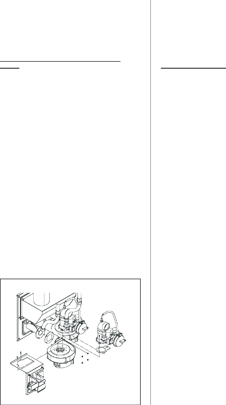
with a new burner. Inspect and replace any
gaskets that may be damaged. Tighten the 4
brass nuts of burner mounting plate to a
torque of 95 in-lb.
8. Leak test the gas train before
re-commissioning the humidifier.
Removal and Installation of the Combustion
Blower
1. Shut off electrical power and gas supply to the
humidifier.
2. Remove the right side service access door.
3. Disconnect all wiring to the combustion
blower, gas valve and air proving switch (note
the connector assignment).
4. Undo the coupling on the flexible gas hose
and disconnect the gas hose from the gas
valve.
5. Undo the 2 screws that mount the gas
valve/air inlet assembly to the blower and
remove the assembly.
6. Undo the 2 screws of the fan-board mounting
bracket (if present) and remove bracket,
leaving electronic board and igniter jump start
module(s) attached.
7. Undo the 4 nuts on the blower outlet and
remove blower.
8. Reverse the sequence above to install the
new combustion blower. Inspect and replace
any gaskets that may be damaged. When
mounting the gas valve/air inlet assembly to
the combustion blower, ensure that the cork
gasket is properly oriented or gas flow through
the valve will be impeded.
9. Leak test the gas train before
re-commissioning the humidifier.
Gas Valve Replacement
1. Shut off electrical power and gas supply to the
humidifier.
2. Remove the right side service access door.
3. Disconnect all wiring to the gas valve and air
proving switch (note the connector
assignment).
4. Undo the coupling on the flexible gas hose
and disconnect the gas hose from the gas
valve.
5. Remove the hoses from the air proving switch
(note the connection layout).
6. Undo the 2 screws that mount the gas
valve/air inlet assembly to the blower and
remove the assembly.
7. Undo the 4 screws and remove the gas pipe
connection from the inlet of the gas pressure
regulating valve.
8. Undo the 3 screws that hold the air inlet
venturi to the gas valve. Remove the rubber
grommet and brass orifice mounted in the
outlet of the gas valve.
9. Undo the 3 screws of the pressure switch
support bracket and remove the assembly
from the gas valve.
10. Reverse the sequence above to install the
new gas pressure regulating valve. Inspect
and replace any gaskets that may be
damaged. When mounting the gas valve/air
inlet assembly to the combustion blower,
ensure that the cork gasket is properly
oriented or gas flow through the valve will be
impeded.
-33-
Figure #29
Combustion Blower Replacement
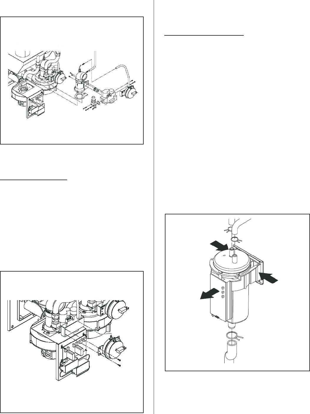
11. Leak test the gas train before
re-commissioning the humidifier.
Air Switch Replacement
1. Shut off electrical power to the appliance.
2. Remove right side service panel.
3. Remove wiring connections to switch.
4. Remove pressure hose(s) from switch noting
proper location.
5. Remove screws (2) holding the switch.
6. Reverse above procedure to re-install.
Float Chamber Replacement
1. Drain the contents of the tank and then shut
off electrical power and water supply to the
humidifier.
2. Remove the left front service access door.
3. Remove the cable connection to the float
board.
4. Remove the hose clamps on the float chamber
and remove all hoses (note the correct hose
assignment).
5. Squeeze both sides of the mounting bracket to
release it from the slots in the support bracket
behind the float chamber.
6. Reverse the above sequence to install the
new module.
7.7. Leak test all water connections before
re-commissioning the humidifier.
-34-
Figure #32
Float Chamber Replacement
Figure #31
Air Switch Replacement
Figure #30
Gas Valve Replacement
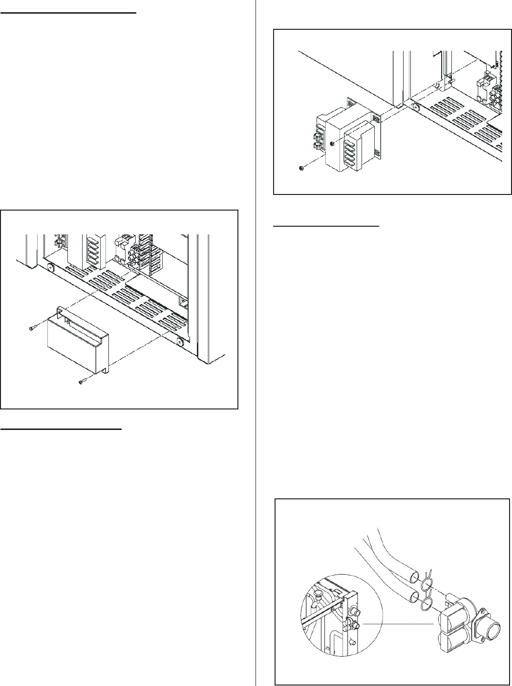
Ignition Module Replacement
1. Shut off electrical power to the humidifier.
2. Remove the front electrical access door.
3. Disconnect all wiring connections to the
ignition module, labeling as required.
4. Remove the 2 screws securing the ignition
module and remove.
5. Reverse the above sequence to install the
new module.
Transformer Replacement
1. Shut off electrical power to the appliance.
2. Remove front access door.
3. Disconnect wiring connections from
transformer leads labeling as required.
4. Remove screws (2) holding transformer.
5. Reverse above procedure to re-install.
Fill Valve Replacement
1. Shut off electrical power and water supply to
the humidifier.
2. Remove the right side service access door.
3. Remove all wiring connections to the fill valve.
4. Remove the hose clamps on the fill valve
outlets and remove hoses (note the correct
hose assignment).
5. Remove the 2 screws securing the fill valve to
the cabinet and remove the valve.
6. Reverse the above sequence to install the
new module.
7.7. Leak test all water connections before
re-commissioning the humidifier.
-35-
Figure #34
Transformer Assembly
Figure #33
Ignition Module Assembly
Figure #35
Fill Valve Replacement
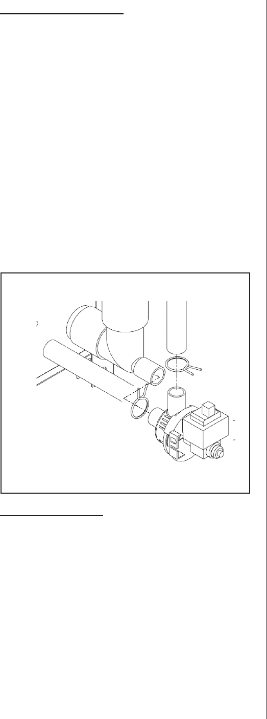
Drain Pump Replacement
1. Drain the unit completely. If the pump is
broken use the auxiliary drain out port.
2. Shut off electrical power to the appliance.
3. Remove front and right doors.
4. Remove wiring connections to the pump.
5. Remove hoses attached to the pump.
6. Reverse above procedure to re-install.
NOTE: To avoid water spillage (some water
will be left on the tank bottom after manual
draining) use shop vac to remove left over
water.
Fill Box Replacement
Leak test all water connections before
re-commissioning the humidifier.
-36-
Figure #36
Drain Pump Assembly
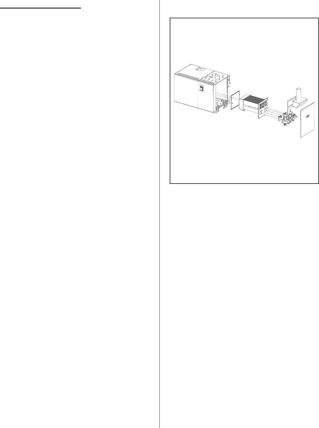
Removal of Heat Exchanger
1.1. Take the humidifier out of operation.
2.2. Disconnect the gas supply pipe from the
connection on the humidifier and close off the
pipe.
3.3. Unlock and remove the right side panel(s).
4.4. On Direct Vent units only: Remove hoses
from air intake manifold and air inlet elbows.
5.5. Dismount flue gas pipe at the flue gas outlet
connection.
6.6. On Direct Vent units only: Dismount air
supply pipe at the air supply connection.
7.7. Unlock and remove the left and the right top
panels.
8.8. Free all cable connections to the components
(combustion blower, ignition module, air
pressure switch, etc.) of the respective heat
exchanger.
IMPORTANT: Note the connector assignment.
9.9. Undo the coupling of the respective flexible
gas pipe and remove the flexible gas pipe.
10.10. Dismount the burner with the air blower and
the gas pressure regulating valve of the
respective heat exchanger.
11. Unscrew the nuts and remove the flue gas
manifold from the tank.
12. Unscrew the nuts on the heat exchanger and
pull out the heat exchanger from the tank.
Re-installation is carried out in the reverse
sequence. Replace all seals with new ones.
-37-
Figure #38
Heat Exchange Assembly
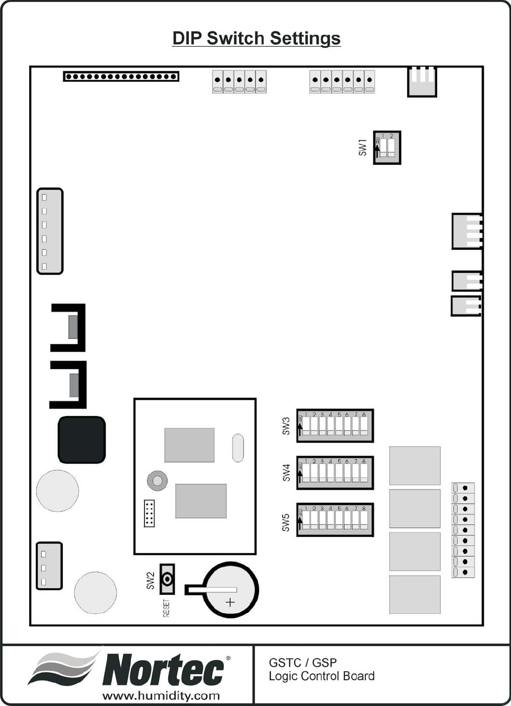
-38-
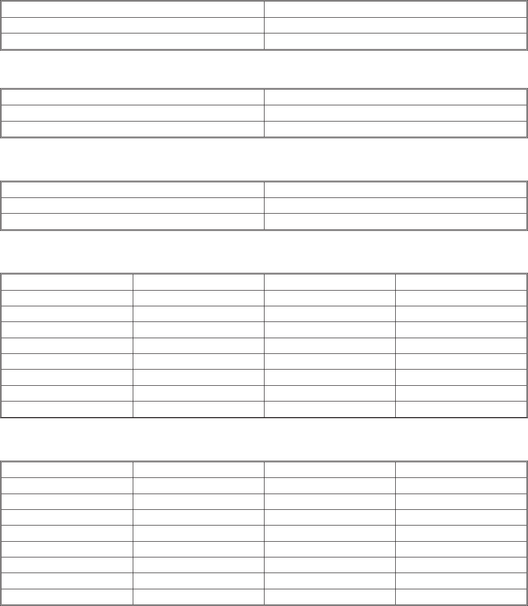
3 DAY DRAIN
3 DAY DRAIN FUNCTION SW3/7
Function Disabled OFF
Function Enabled (Factory set) ON
KEEP WARM
3 DAY DRAIN FUNCTION SW5/7
Function Enabled ON
Function Disabled (Factory set) - 3 day drain OFF
MAINTENANCE (GSP)
MAINTENANCE INTERVAL (GSP) SW3/8
500 hour (Factory set) OFF
1000 hour ON
ANALOG CHANNEL 1
Input Range SW1/1 SW4/1 SW 4/2
0-10V input OFF OFF OFF
0-5V input OFF ON OFF
2-10V input OFF OFF ON
1-5V input OFF ON ON
0-20mA input ON OFF OFF
0-10mA input ON ON OFF
4-20mA input ON OFF ON
2-10mA input ON ON ON
ANALOG CHANNEL 2
Input Range SW1/2 SW4/3 SW 4/4
0-10V input OFF OFF OFF
0-5V input OFF ON OFF
2-10V input OFF OFF ON
1-5V input OFF ON ON
0-20mA input ON OFF OFF
0-10mA input ON ON OFF
4-20mA input ON OFF ON
2-10mA input ON ON ON
-39-
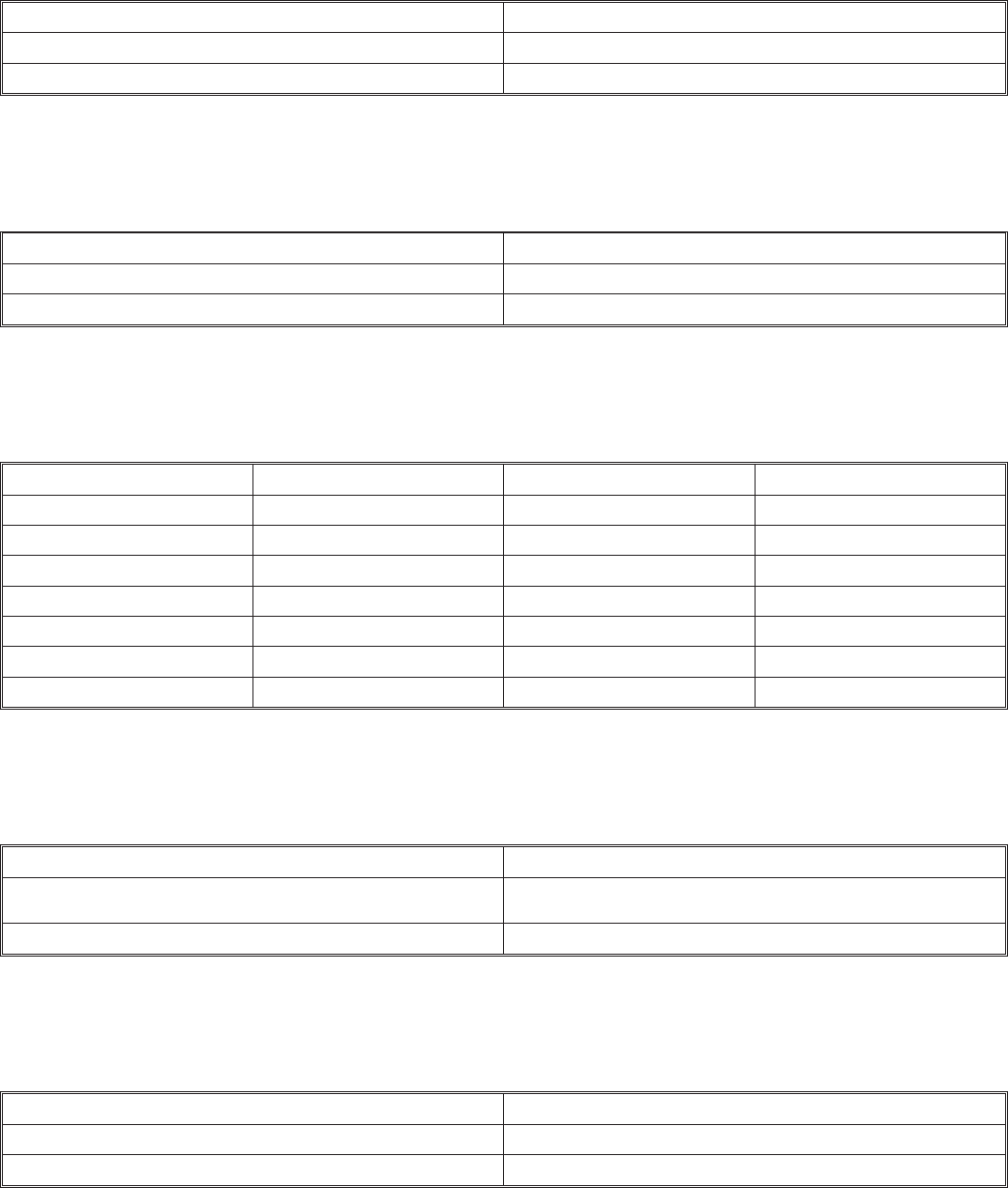
INPUT CHANNEL
DUAL CHANNEL FUNCTION SW4/5
One Channel Input OFF
Dual Channel Inputs ON
TIME PROPORTIONING
TIME PROPORTIONING SW4/7
Disabled (Factory set) OFF
Enabled ON
BLOWDOWN (GSP)
BLOWDOWN SW5/1 SW 5/2 SW5/3
5% ON OFF OFF
10% OFF ON OFF
15% ON ON OFF
20% OFF OFF ON
25% (Factory set) ON OFF ON
30% OFF ON ON
35% ON ON ON
MAINTENANCE SHUTDOWN
MAINTENANCE SHUTDOWN FUNCTION SW5/4
Unit will shutdown 72 hours after service time expired, by gen-
erating an error. OFF
Unit will display warning but continues to operate. (Factory set) ON
FULL TANK BLOWDOWN
FULL TANK BLOWDOWN FUNCTION SW5/8
Disabled OFF
Enabled (Factory set) ON
-40-

NORTEC GSTC-400
VERSION X.XX
SYSTEM LOCKOUT
09.05.02 9:30
SYSTEM STATUS
USER SETTINGS
SERVICE LEVEL
MENU
MENU
USE THE
UP/DOWN
ARROWS
TO MOVE THE
POINTER TO
SELECT A
MENU ITEM.
TO OPEN THE
SELECTION,
PRESS THE ENTER
BUTTON.
INTRODUCTORY SCREEN MAIN MENU
Keypad Display Menu Structure
GENERAL
NORTEC TC CONTROLLER
Menu Structure
NOTES:
Go To: System Status - page 22
Service Level - page 24
User Setting - page 26
-41-
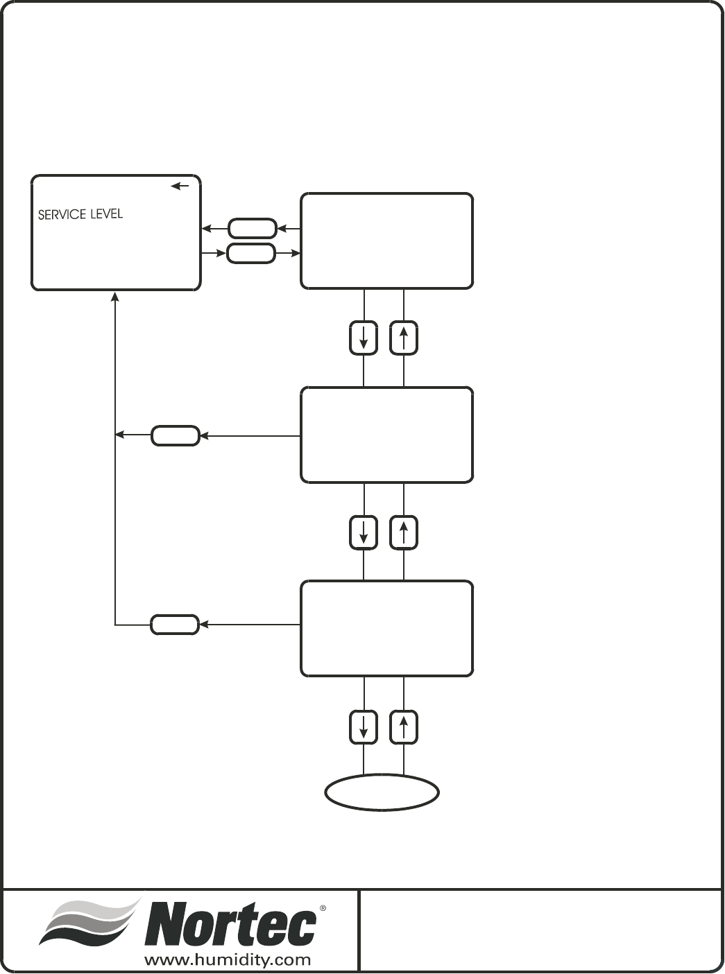
MENU
MENU
ENTER
MENU
MAIN MENU
SYSTEM STATUS
USER SETTINGS
STATUS: LOCKOUT
DEMAND CHANNEL 1 0%
DEMAND CHANNEL 2 0%
CAPACITY LIMIT 0%
1
2
SYSTEM DEMAND XXX%
BURNERS ACTIVE X/X
OUTPUT/BURNER XXXLB
TOTAL OUTPUT XXXLB
1
2
3
WATER LEVEL: X
FILL VALVE ON
DRAIN VALVE OFF
DRAIN COOLING: SMART
1
4
2
3
1. DISPLAY TOGGLES BETWEEN
LOCKOUT, ACTIVE, AND STANDBY,
DEPENDING ON SYSTEM DEMAND
2. ONLY VIEWED IF UNIT
IS CONFIGURED FOR
DUAL CHANNEL.
1. DISPLAY WILL SHOW NUMBER
OF BURNERS AND
DISPLAYS THE NUMBER OF
ACTIVE BURNERS.
2. DISPLAYS THE OUTPUT PER
BURNER IN POUNDS PER HOUR
OR KG/HR.
3. DISPLAY OF TOTAL SYSTEM
OUTPUT IN LBS/HR [KG/HR]
1. DEPENDING ON WATER LEVEL,
WILL DISPLAY 0 - 5.
2. TOGGLES BETWEEN ON, OFF,
AND PULSED.
3. TOGGLES BETWEEN ON AND OFF
4. DISPLAYS USER SETTING, ON, OFF,
OR SMART
SYSTEM STATUS
2
Keypad Display Menu Structure
System Status 1 of 2
SYSTEM STATUS 1 of 2
-42-
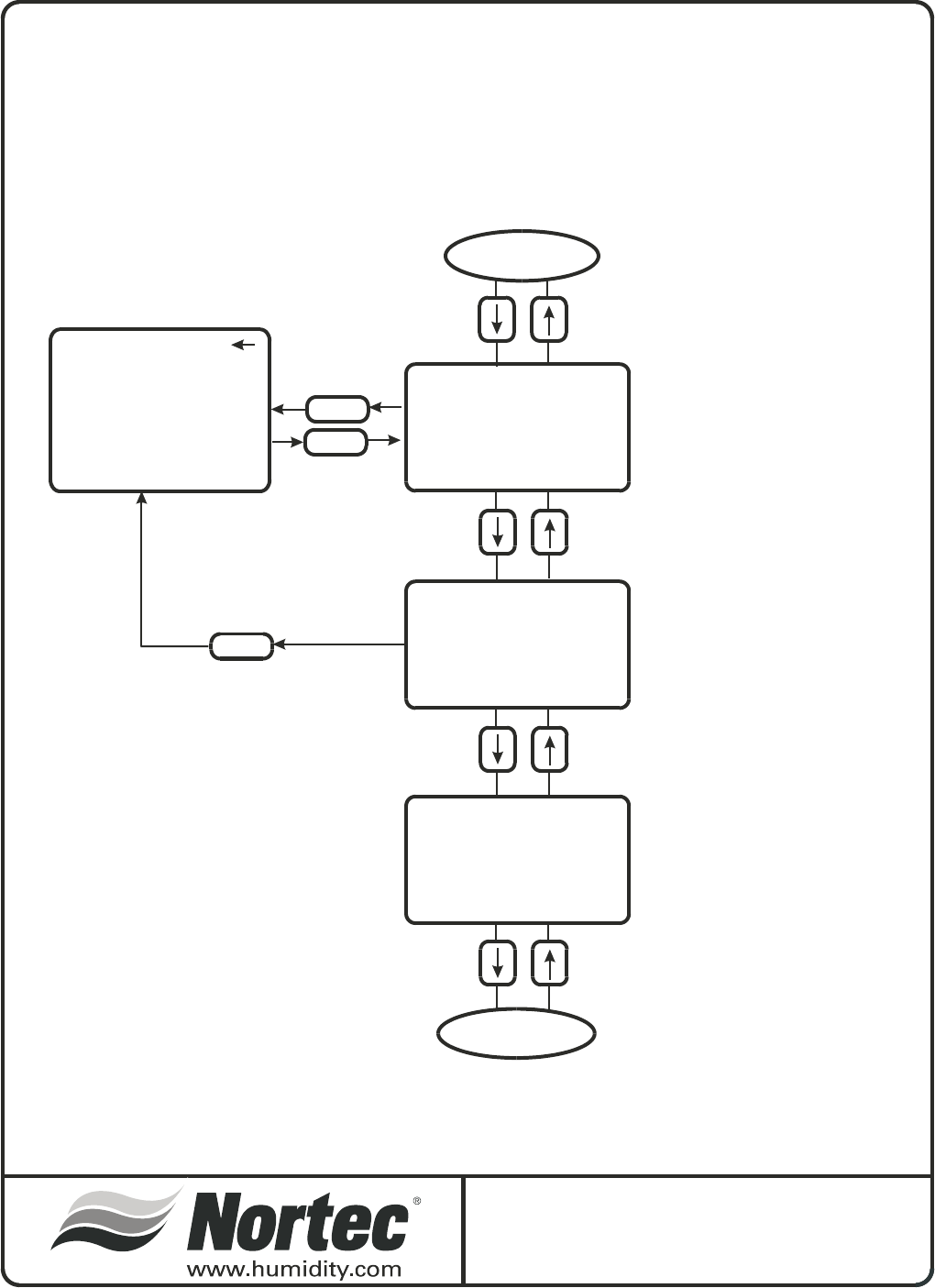
MENU
SERVICE INTERVAL
SECURITY LOOP [0/1]
3DAYDRAIN ON
SAFETY SENSORS [0/1]
KEEP WARM OFF
TANK SENSORS [0/1]
BLOWDOWN RATE 25%
FT BLOWDOWN ON
XXX HOURS
START DATE: MM:DD:YY
REMAINING XXX HOURS
1
1
1
3
3
4
2
2
2
3
1. DISPLAYS THE USER
SELECTABLE MAINTENANCE
INTERVAL
1. DISPLAYS STATUS OF THE
SECURITY LOOP
(O = OPEN I = CLOSED)
1. DISPLAYS IF FEATURE IS
SELECTED
2. DISPLAYS STATUS OF THE
SAFETY SENSORS
2. DISPLAYS IF FEATURE IS
SELECTED
3. DISPLAYS STATUS OF THE
TANK SENSOR
3. DISPLAYS PRESENT
BLOWDOWN RATE
4. DISPLAYS IF FEATURE
IS SELECTED.
3. DISPLAYS THE START DATE
OF THE CURRENT SERVICE
INTERVAL
2. DISPLAYS THE TIME LEFT
BEFORE MAINTENANCE
IS DUE
LOOP BACK
ENTER
MENU
MAIN MENU
SYSTEM STATUS
USER SETTINGS
SERVICE LEVEL
SYSTEM STATUS
1
Keypad Display Menu Structure
System Status 2 of 2
SYSTEM STATUS 2 of 2
-43-
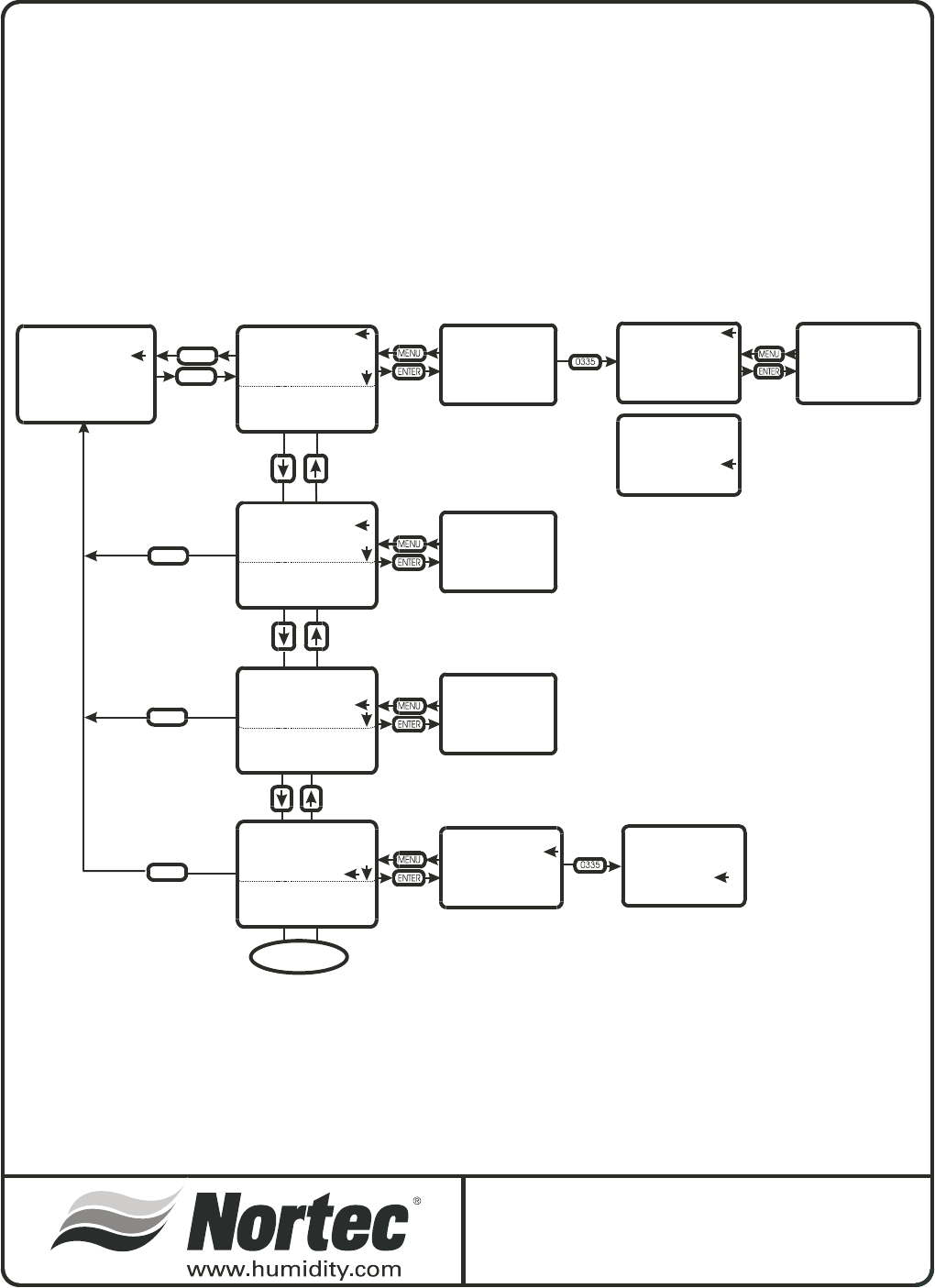
ENTER
MENU
MENU
MENU
MENU
MAIN MENU
SYSTEM STATUS
SERVICE LEVEL
USER SETTINGS
SERVICE INTERVAL
XXX HOURS
SERVICE HISTORY X/Y
STEAM HOURS XXXX
(DATE/TIME)
FAULT HISTORY X/Y
(TYPE OF FAULT)
(DATE/TIME)
THIS WILL DRAIN
CONTENTS OF TANK
THIS WILL DRAIN
CONTENTS OF TANK
CONTINUE?
SERVICE INTERVAL
XXX HOURS
SERVICE INTERVAL
XXX HOURS
CLEAR REMAINDER?
CLEAR REMAINDER?
SERVICE (HR)
CHANGE VALUE XXX
SERVICE INTERVAL
SERVICE HISTORY
FAULT HISTORY
TANK DRAIN
TANK PRE-CLEAN
SHORT CYCLE DELAY
BURNERS
1
SERVICE INTERVAL
SERVICE INTERVAL
SERVICE INTERVAL
SERVICE HISTORY
SERVICE HISTORY
SERVICE HISTORY
FAULT HISTORY
FAULT HISTORY
FAULT HISTORY
TANK DRAIN
TANK DRAIN
TANK DRAIN
TANK PRE-CLEAN
TANK PRE-CLEAN
TANK PRE-CLEAN
SHORT CYCLE DELAY
SHORT CYCLE DELAY
SHORT CYCLE DELAY
BURNERS
BURNERS
BURNERS
2
3
1. VERTICAL ARROW INDICATES ADDITIONAL
SELECTIONS AVAILABLE BY SCROLLING.
2. USE UP DOWN ARROWS TO
CHANGE HOURS
3. PRESSING ENTER CLEARS
THE REMINDER
1
1
1
2
2
3
3
1. DISPLAYS THE LAST 10 SERVICE
PERIODS
1. DISPLAYS THE LAST 54
FAULTS
1. PRESSING ENTER STARTS THE
TANK DRAIN PROCEEDURE
2. DISPLAYS THE NUMBER OF STEAM
HOURS WHEN SERVICE WAS
PERFORMED
2. GIVES A DESCRIPTION OF
THE FAULT TYPE
3. DISPLAYS THE DATE THE SERVICE
WAS PERFORMED
3. DISPLAYS THE DATE THE
FAULT OCCURRED.
SERVICE LEVEL
2
Keypad Display Menu Structure
Service Level 1 of 2
SERVICE LEVEL 1 of 2
-44-
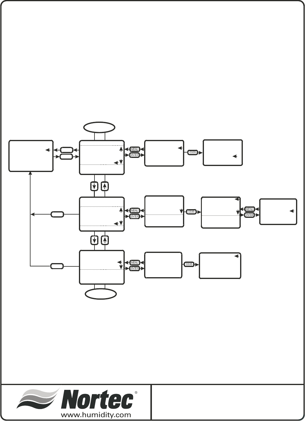
ENTER
MENU
MENU
MENU
MAIN MENU
SYSTEM STATUS
SERVICE LEVEL
USER SETTINGS
SHORT CYCLE DELAY
SECONDS XX
SHORT CYCLE DELAY
CHANGE VALUE XX
BURNER 1
ENABLED
DISABLED
THIS WILL DRAIN
CONTENTS OF TANK
THIS WILL DRAIN
CONTENTS OF TANK
CONTINUE?
SERVICE INTERVAL
SERVICE HISTORY
FAULT HISTORY
TANK DRAIN
TANK PRE-CLEAN
SHORT CYCLE DELAY
BURNERS
1
SERVICE INTERVAL BURNER 1: ENABLED BURNER 1: ENABLED
BURNER 2: ENABLED BURNER 2: ENABLED
BURNER 3: ENABLED BURNER 3: ENABLED
BURNER 4: ENABLED BURNER 4: ENABLED
BURNER 5: ENABLED BURNER 5: ENABLED
BURNER 6: ENABLED BURNER 6: ENABLED
SERVICE INTERVAL
SERVICE HISTORY
SERVICE HISTORY
FAULT HISTORY
FAULT HISTORY
TANK DRAIN
TANK DRAIN
TANK PRE-CLEAN
TANK PRE-CLEAN
SHORT CYCLE DELAY
SHORT CYCLE DELAY
BURNERS
BURNERS
1. VERTICAL ARROW INDICATES ADDITIONAL
SELECTIONS AVAILABLE BY SCROLLING.
1
1. PRESSING ENTER STARTS THE TANK DRAIN PROCEDURE
END
SERVICE LEVEL
1
Keypad Display Menu Structure
Service Level 2 of 2
SERVICE LEVEL 2 of 2
-45-
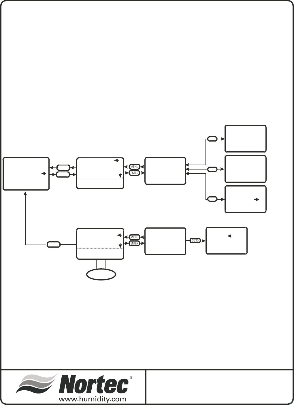
ENTER
MENU
MENU
MAIN MENU
SYSTEM STATUS
SERVICE LEVEL
USER SETTINGS
TIME HH:MM
DATE MM.DD.YY
UNITS: LB/HR
DATE/TIME/UNITS
LANGUAGE CONTROLS
WATER MANAGEMENT
CONTROL TYPE
CAPACITY LIMIT
CALIBRATE
1
1. VERTICAL ARROW INDICATES ADDITIONAL
SELECTIONS AVAILABLE BY SCROLLING.
SELECT LANGUAGE
ENGLISH
FRENCH
GERMAN
SELECT LANGUAGE
ENGLISH
FRENCH
GERMAN
DATE/TIME/UNITS
LANGUAGE CONTROLS
WATER MANAGEMENT
CONTROL TYPE
CAPACITY LIMIT
CALIBRATE
1
SELECT UNITS
LB/HR
KG/HR
CHANGE DATE
MM.DD.YY
CHANGE TIME
XX:XX
0335
0335
0335
PRESS ENTER TO
SELECT UNITS
PRESS ENTER TO
SELECT LANGUAGE
USER SETTINGS
2
Keypad Display Menu Structure
UserSetting1of3
USER SETTINGS 1 of 3
-46-
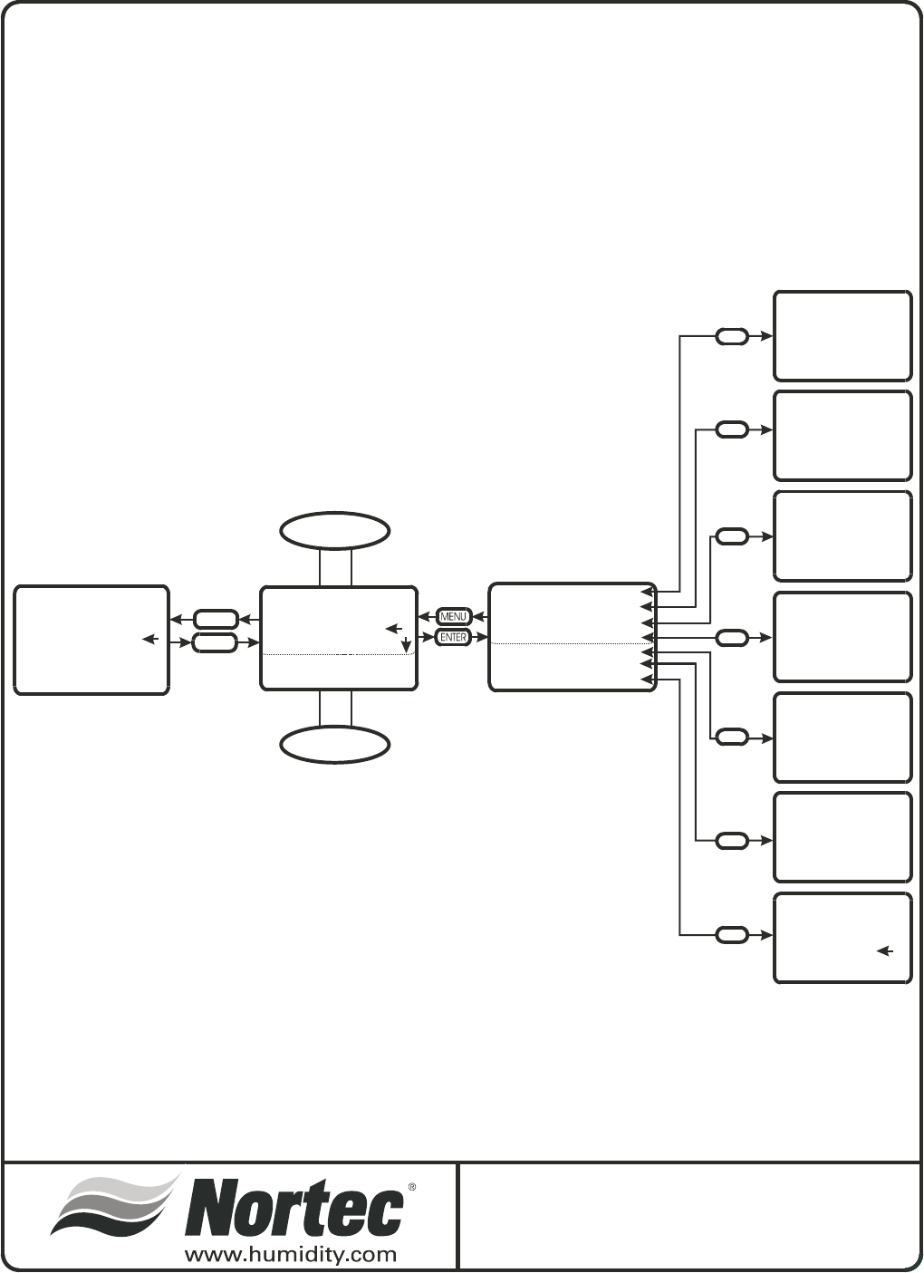
FTBD HOURS
CHANGE HOURS? XXX
FTBD HOUR
CHANGE HOUR? XX
FILL CORRCTN
CHANGE VALUE XXX%
FLOAT CHECK
CHANGE VALUE HH:MM
DRAIN CORRCTN
CHANGE VALUE XXX%
DRAIN COOL
ON
OFF
SMART
BLOWDOWN RATE
CHANGE VALUE XX%
STEAM OUTPUT
ENTER
MENU
MAIN MENU
SYSTEM STATUS
SERVICE LEVEL
USER SETTINGS
DATE/TIME/UNITS FTBD HOURS XXX
FTBD HOUR XX
BLOWDOWN RATE XX%
FLOAT CHECK HH:MM
FILL CORRCTN XX%
DRAIN CORRCTN XX%
DRAIN COOL: SMART
LANGUAGE CONTROLS
WATER MANAGEMENT
CONTROL TYPE
CAPACITY LIMIT
CALIBRATE
1
1. VERTICAL ARROW INDICATES
ADDITIONAL SELECTIONS
AVAILABLE BY SCROLLING.
USER SETTINGS
PAGE 1
USER SETTINGS
3
0335
0335
0335
0335
0335
0335
0335
Keypad Display Menu Structure
UserSetting2of3
USER SETTINGS 2 of 3
-47-
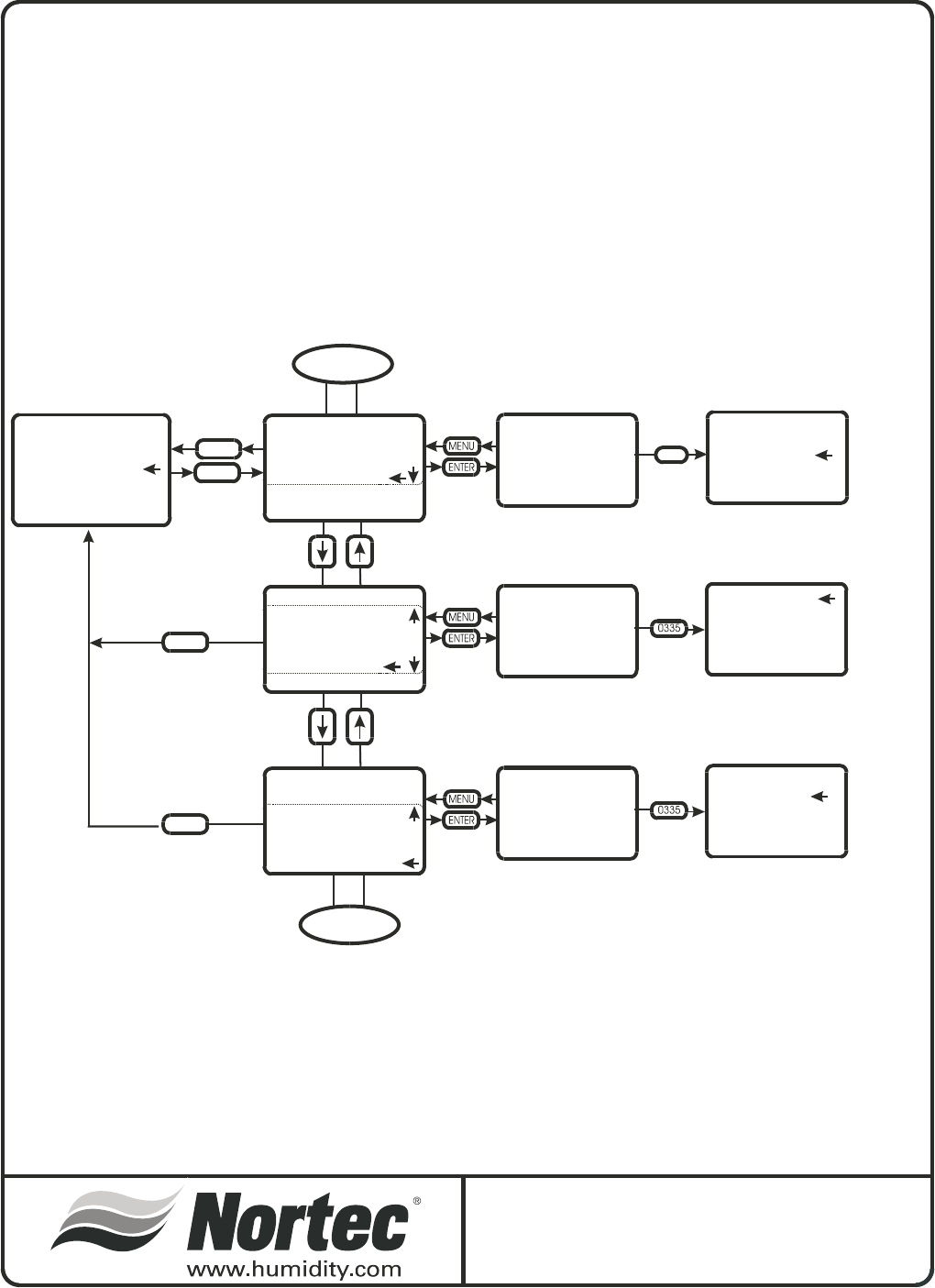
MENU
MENU
SET MAXIMUM
CAPACITY XXX%
SET MAXIMUM
CAPACITY XXX%
CALIBRATE
SIGNAL?
CALIBRATE
SIGNAL
CALIBRATE 4957
DATE/TIME/UNITS
DATE/TIME/UNITS
LANGUAGE CONTROLS
LANGUAGE CONTROLS
WATER MANAGEMENT
WATER MANAGEMENT
CONTROL TYPE
CONTROL TYPE
CAPACITY LIMIT
CAPACITY LIMIT
CALIBRATE
CALIBRATE
USE
UP/DOWN
ARROWS
TO SET
MAXIMUM
CAPACITY
PRESS
ENTER TO
CALIBRATE
SIGNAL
END
ENTER
MENU
MAIN MENU
SYSTEM STATUS
SERVICE LEVEL
USER SETTINGS
CONTROL TYPE
CONTROL INPUT
TRANSDUCER INPUT
CONTROL TYPE
CONTROL INPUT
TRANSDUCER INPUT
DATE/TIME/UNITS
LANGUAGE CONTROLS
WATER MANAGEMENT
CONTROL TYPE
CAPACITY LIMIT
CALIBRATE
1
1. VERTICAL ARROW INDICATES ADDITIONAL
SELECTIONS AVAILABLE BY SCROLLING.
0335
PRESS
ENTER TO
SELECT
CONTROL
TYPE
USER SETTINGS
2
Keypad Display Menu Structure
UserSetting3of3
USER SETTINGS 3 of 3
-48-
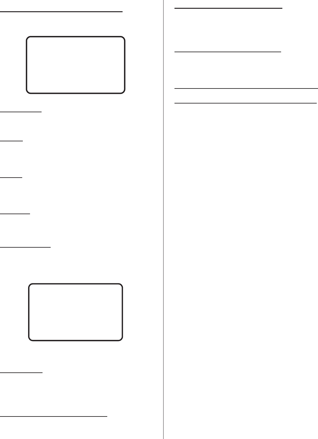
-49-
NORTEC TC CONTROLLER
INTRODUCTORY SCREEN
Product name
NORTEC GSTC (100-600)
Version
The display will indicate the revision level of the
control software
System
Depending on system activity, the display will
toggle between LOCKOUT, ACTIVE or STANDBY.
Date/Time
The actual date and time will be displayed.
MAIN MENU
The main menu lists the available sub menus
where system adjustments can be made. Some of
the menus are password and jumper protected to
block access by unauthorized personnel.
System status
Displays various system parameters as the user
scrolls through the lists. For further details see specific
section below.
Service Level: (password protected)
This section is specific to all service related
activity. For further details see specific section below.
User Settings: (password protected)
This section allows the user to set parameters
specific to their requirements. For further details see
specific section below.
Diagnostics: (safety loop protected)
Allows the user to activate and monitor various
system operations.
Service checklist: (not available for first release)
Troubleshooting: (not available for first release)
NORTEC GSTC-400
VERSION X.XX
SYSTEM LOCKOUT
06.07.03 9:30
SYSTEM STATUS
SERVICE LEVEL
USER SETTINGS
DIAGNOSTICS
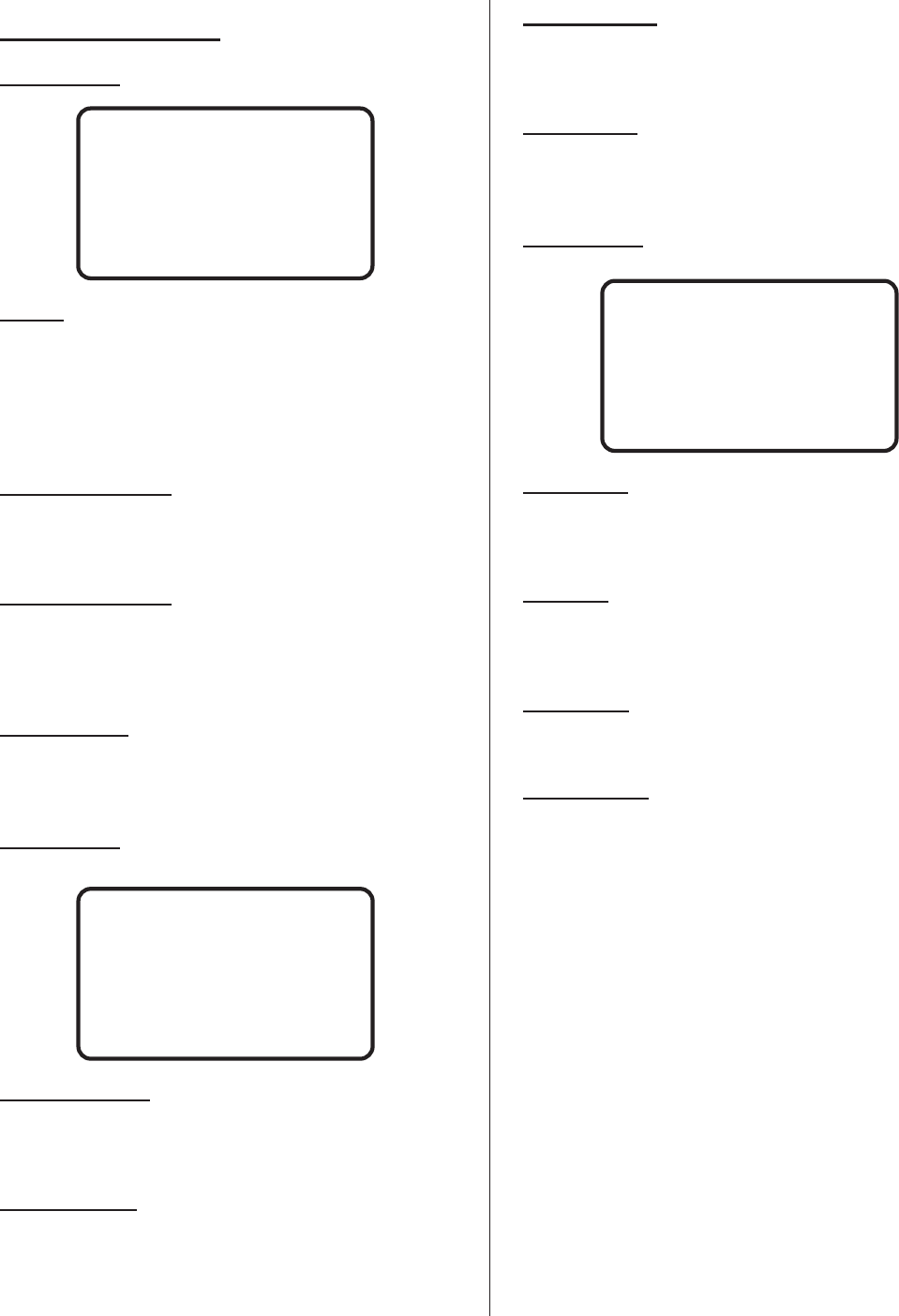
-50-
SYSTEM STATUS
SCREEN 1:
Status:
Displays the present status of the system.
Depending on system activity at the time, the field
could display: lockout (security loop open), active (unit
generating steam) or standby (security loop closed but
no modulation demand signal).
Demand channel 1:
This field will display the modulation demand input
on that channel.
Demand channel 2:
Field only visible if the unit is configured for dual
modulation. This field will display the modulation
demand input on that channel.
Capacity limit:
This field displays the user adjusted capacity limit
set for the humidifier.
SCREEN 2:
System demand:
This field displays the total system demand as a
percentage.
Burners active:
This field displays the number of active burners
and the number of available burners.
Output/Burner:
This field will display the actual output of steam
generated by each burner (kg/hr or lbs/hr).
Total output:
This field will display the total system steam output
(kg/hr or lbs/hr).
SCREEN 3:
Water level:
This field displays the present water level detected
by the float system.
Fill valve:
This field displays status of fill valve, on, off, or
pulsed.
Drain valve:
This field displays status of drain pump, on or off.
Drain cooling:
This field displays the user (or factory default)
setting.
OFF: fill will not activate when drain is activated.
ON: fill will activate whenever the drain activates.
SMART: fill will activate only when drain water is
hot.
STATUS: LOCKOUT
DEMAND CHANNEL 1 0%
DEMAND CHANNEL 2 0%
CAPACITY LIMIT 0%
SYSTEM DEMAND XXX%
BURNERS ACTIVE X/X
OUTPUT/BURNER XXXLB
TOTAL OUTPUT XXXLB
WATER LEVEL: X
FILL VALVE ON
DRAIN VALVE OFF
DRAIN COOLING: SMART
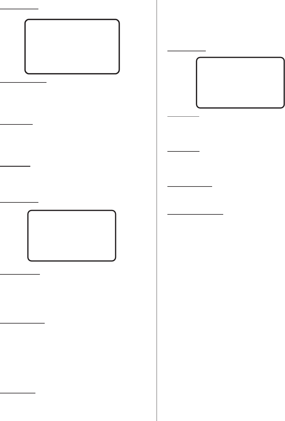
SCREEN 4:
Service interval:
This field displays the user (or factory default)
setting for the humidifiers service reminder in steam
hours.
Remaining:
This field displays the amount of time (steam
hours) remaining before the next service is to be
performed.
Start Date:
This field displays the date this service interval
began.
SCREEN 5:
Security loop:
This field displays the status of the security loop
(terminals 1 and 2 on LV terminal strip). If it is open
the display will indicate “O”, if it is closed the display
will indicate “I”.
Safety sensors:
This field displays the status of the safety sensors*
input. If it is open the display will indicate “0”, if it is
closed the display will indicate “1”.
*There are two safety sensors on the GSTC. One
for tank over temperature and one for stack over
temperature. Both sensors are wired in series.
Tank sensor
This field displays the status of the tank sensor
input. If it is open the display will indicate “0”, if it is
closed the display will indicate “1”. Closed indicates
that the tank temperature is above 160ºF (70ºC).
This input is used for the “keep warm” feature and
for activating the fill valve during blowdown cycles.
SCREEN 6:
3 day drain
This field indicates if the feature has been selected
(0 = no, 1 = yes).
Keep warm
This field indicates if the feature has been selected
(0 = no, 1 = yes).
Blowdown rate:
This field displays the selected blowdown rate.
Full tank blowdown
This field indicates if the feature has been selected
(0 = no, 1 = yes).
-51-
SECURITY LOOP [0/1]
SAFETY SENSORS [0/1]
TANK SENSORS [0/1]
3 DAY DRAIN 1
KEEP WARM 0
BLOWDOWN RATE XX%
FT BLOWDOWN 1
SERVICE INTERVAL
XXX HOURS
START DATE: MM:DD:YY
REMAINING XXX HOURS
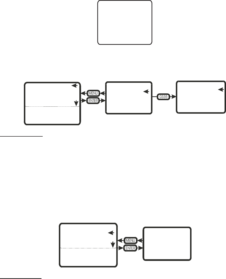
-52-
SERVICE LEVEL
The service level area is where service related tasks are performed. Below is a description of each field and what
can be performed in them. When a parameter requires a change, press the two arrow keys and enter the password
(0335). As long as you remain in this section, you will not need to enter the password more than once.
Service interval
In this area the customer can set a service interval for humidifier MAINTENANCE.
MAINTENANCE TIME
XXX HOURS
This field displays the user selected MAINTENANCE time. To change the time selected enter the user code and
adjust the time in SET MAINT. TIME (0-3000 hours, 0 = disabled).
MAINTENANCE DUE
XXX HOURS
This field displays the time remaining until the next service interval. To reset the MAINTENANCE due time, enter
the user code and select CLEAR REMINDER?
Service history
In this area the customer can view the history of service maintenance performed on the humidifier.
SERVICE HISTORY X/Y
The service history stores the last 10 service periods.
X = service occurrence, where 1 is the most recent.
SERVICE INTERVAL
SERVICE HISTORY
FAULT HISTORY
TANK DRAIN
TANK PRE-CLEAN
BURNERS
SHORT CYCLE DELAY
MAINTENANCE TIME
XXX HOURS
MAINTENANCE DUE
XXX HOURS
SERVICE INTERVAL
XXX HOURS
CLEAR REMAINDER?
SERVICE INTERVAL
SERVICE HISTORY
FAULT HISTORY
TANK DRAIN
TANK PRE-CLEAN
SHORT CYCLE DELAY
BURNERS
1
SERVICE HISTORY X/Y
STEAM HOURS XXXX
(DATE/TIME)
SERVICE INTERVAL
SERVICE HISTORY
FAULT HISTORY
TANK DRAIN
TANK PRE-CLEAN
SHORT CYCLE DELAY
BURNERS
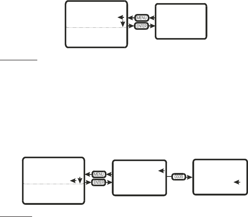
Y = total number of recorded services (up to 10 maximum).
STEAM HOURS XXX
(DATE/TIME)
This field displays the steam hours and the date and time when the specific service (X) was performed.
Fault history
In this area the customer can view the history of recorded faults for the humidifier.
FAULT HISTORY X/Y
The fault history stores the last 54 system faults.
X = fault occurrence, where 1 is the most recent.
Y = total number of recorded faults (up to 54 maximum).
(type of fault) and (date/time)
A description of the fault type is displayed along with a date and time stamp when the fault occurred.
Tank Drain
The tank drain feature, when activated, will activate the drain valve for a fixed period of time (depending on unit
size).
To drain the tank press enter when CONTINUE is selected. During the tank drain cycle the display will indicate
the tank is draining and the amount of time remaining on the cycle. To interrupt the cycle the unit must be switched off
then on. Must enter service password to activate this function.
FAULT HISTORY X/Y
(TYPE OF FAULT)
(DATE/TIME)
SERVICE INTERVAL
SERVICE HISTORY
FAULT HISTORY
TANK DRAIN
TANK PRE-CLEAN
SHORT CYCLE DELAY
BURNERS
THIS WILL DRAIN
CONTENTS OF TANK
THIS WILL DRAIN
CONTENTS OF TANK
CONTINUE?
SERVICE INTERVAL
SERVICE HISTORY
FAULT HISTORY
TANK DRAIN
TANK PRE-CLEAN
SHORT CYCLE DELAY
BURNERS
-53-
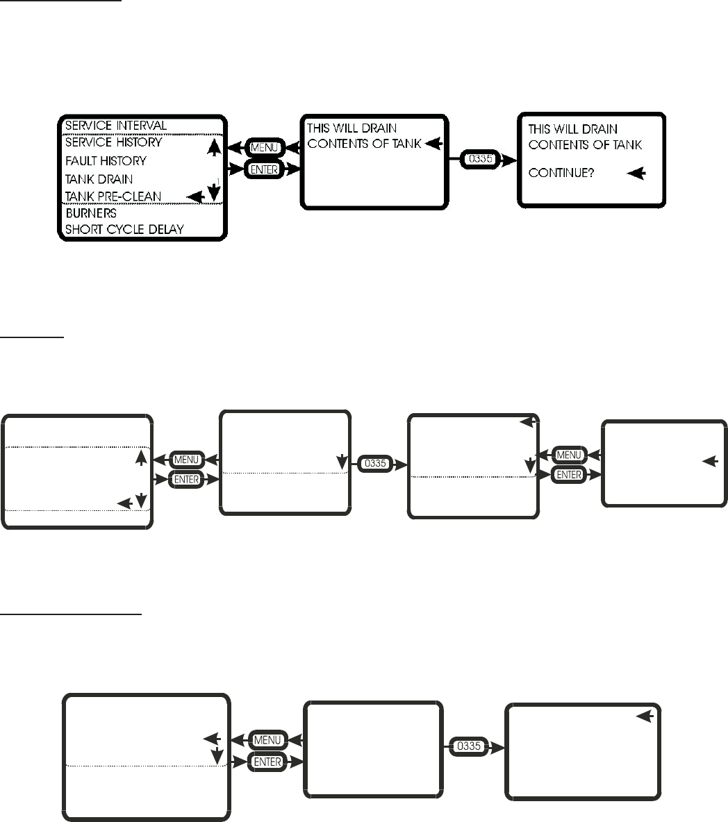
Tank Pre-Clean
The tank pre-clean feature when activated will activate the drain valve for a fixed period of time (depending on
unit size). The fill valve will then activate, filling the tank partially with cold water. At the completion of the fill cycle the
tank will once again drain.
This will help to flush out any accumulated minerals as well as cool the tank for the service personnel.
To pre-clean the tank press enter when CONTINUE is selected. During the tank pre-clean cycle the display will
indicate the tank is draining and the amount of time remaining on the cycle. To interrupt the cycle the unit must be
switched off then on. Must enter service password to activate this function.
Burners
This field allows the user to enable and disable individual burners for service reasons. Depending on the GSTC
model, only the number of burners installed will be displayed
After entering the user code (0335) the individual burner can be highlighted. Once ENTER is pressed, the burner
can be enabled or disabled.
Short Cycle Delay
The short cycle delay feature can be used to reduce the amount of ON/OFF cycles during operation. The feature
will cause a delay between cycles by forcing the system to wait a pre set period (seconds) before responding to a
demand signal.
The delay can be set from 1 to 1000 seconds. The default shall be 1 second since any larger value can result in a
less dynamic response of the system as a whole. This feature should only be used once a short cycle condition has
been identified.
BURNER 1
ENABLED
DISABLED
SERVICE INTERVAL BURNER 1: ENABLED BURNER 1: ENABLED
BURNER 2: ENABLED BURNER 2: ENABLED
BURNER 3: ENABLED BURNER 3: ENABLED
BURNER 4: ENABLED BURNER 4: ENABLED
BURNER 5: ENABLED BURNER 5: ENABLED
BURNER 6: ENABLED BURNER 6: ENABLED
SERVICE HISTORY
FAULT HISTORY
TANK DRAIN
TANK PRE-CLEAN
SHORT CYCLE DELAY
BURNERS
SHORT CYCLE DELAY
SECONDS XX
SHORT CYCLE DELAY
CHANGE VALUE XX
SERVICE INTERVAL
SERVICE HISTORY
FAULT HISTORY
TANK DRAIN
TANK PRE-CLEAN
SHORT CYCLE DELAY
BURNERS
-54-
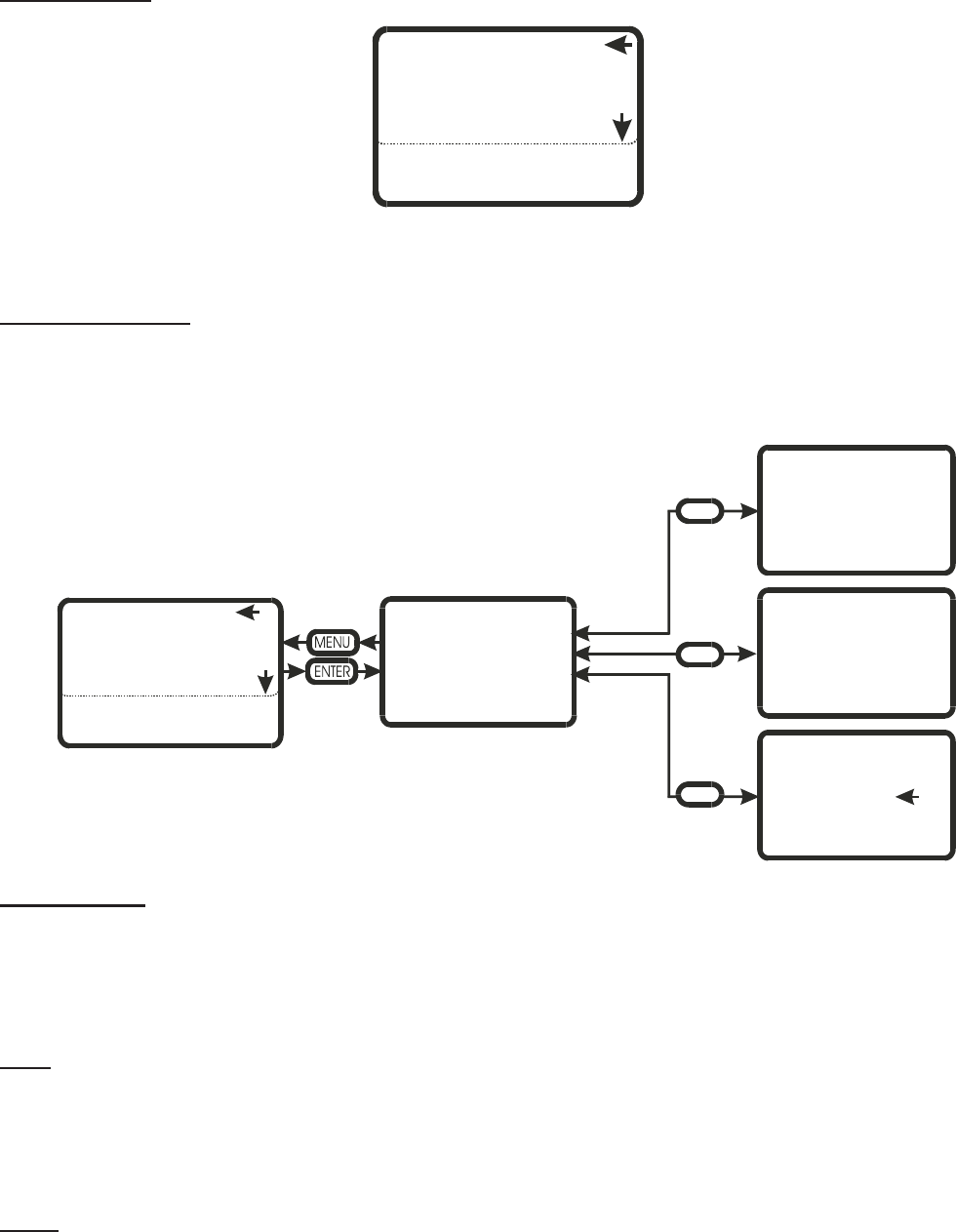
-55-
User Settings
When a parameter requires a change, press the two arrow keys and enter the password (0335). As long as you
remain in this section, you will not need to enter the password more than once.
Date / Time Units
This field is used for modifying the Date, time and the units of measurement. The date and time are important
parameters when features such as full tank blowdown are enabled.
Time (of day)
To set the time of day, highlight the selection then enter the user code (0335). Press enter. Use the UP/DOWN
arrows to adjust the hours (24 hour format). Pressing enter saves the setting and indexes the display to minutes. Use
the UP/DOWN arrows to adjust the minutes. Pressing enter saves the setting and returns the user to the previous
menu.
Date
To set the date, highlight the selection then enter the user code (0335). Press enter. Use the UP/DOWN arrows to
select the month. Pressing enter saves the setting and indexes the display to number of the month. Use the
UP/DOWN arrows to adjust the number. Pressing enter saves the setting and indexes the display to year. Use the
UP/DOWN arrows to adjust the year. Pressing enter saves the setting and returns the user to the previous menu.
Units
Here the user can select the unit of steam production rate. To set the units, highlight the selection then enter the
user code (0335). Press enter. Use the UP/DOWN arrows to select the units (LB/HR or KG/HR). Pressing enter saves
the setting and returns the user to the previous menu.
DATE/TIME/UNITS
LANGUAGE CONTROLS
WATER MANAGEMENT
CONTROL TYPE
CAPACITY LIMIT
CALIBRATE
TIME HH:MM
DATE MM.DD.YY
UNITS: LB/HR
DATE/TIME/UNITS
LANGUAGE CONTROLS
WATER MANAGEMENT
CONTROL TYPE
CAPACITY LIMIT
CALIBRATE
1
SELECT UNITS
LB/HR
KG/HR
CHANGE DATE
MM.DD.YY
CHANGE TIME
XX:XX
0335
0335
0335
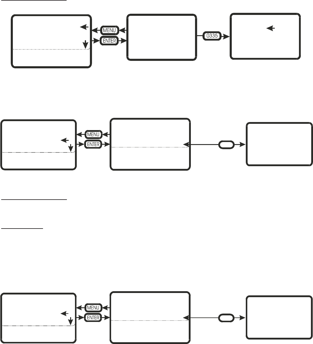
Language Controls
This field allows the user to select the menu language of choice (English, French, German)
Here the user can select the language of choice for the menu displays. To set the language, highlight the
selection then enter the user code (0335). Press enter. Use the UP/DOWN arrows to select the choice (English,
French, German). Pressing enter saves the setting and returns the user to the previous menu.
NOTE: ONLY ENGLISH AVAILABLE AS OF 05/03
Water Management
This section allows the user to set time based parameters and adjust water control parameters.
FTBD Hours
This section allows the user to set the frequency of full tank blowdowns (FTBD). FTBD’s drains and re-fills the
entire contents of the humidifier after a preset accumulated operating time. Run time is measured in steam hours
(weighted run time hours), and can be adjusted from 0 hours (feature off) to 400 hours in 25 hour increments.
Once the FTBD time has expired, the controller will wait until the FTBD hour to initiate the cycle. This prevents
random drains at times when they would be inconvenient.
SELECT LANGUAGE
ENGLISH
FRENCH
GERMAN
SELECT LANGUAGE
ENGLISH
FRENCH
GERMAN
DATE/TIME/UNITS
LANGUAGE CONTROLS
WATER MANAGEMENT
CONTROL TYPE
CAPACITY LIMIT
CALIBRATE
FTBD HOURS
CHANGE HOURS? XXX
DATE/TIME/UNITS FTBD HOURS XXX
FTBD HOUR XX
BLOWDOWN RATE XX%
FLOAT CHECK HH:MM
FILL CORRCTN XX%
DRAIN CORRCTN XX%
DRAIN COOL: SMART
LANGUAGE CONTROLS
WATER MANAGEMENT
CONTROL TYPE
CAPACITY LIMIT
CALIBRATE
0335
FTBD HOUR
CHANGE HOUR? XXX
DATE/TIME/UNITS FTBD HOURS XXX
FTBD HOUR XX
BLOWDOWN RATE XX%
FLOAT CHECK HH:MM
FILL CORRCTN XX%
DRAIN CORRCTN XX%
DRAIN COOL: ON
LANGUAGE CONTROLS
WATER MANAGEMENT
CONTROL TYPE
CAPACITY LIMIT
CALIBRATE
0335
-56-
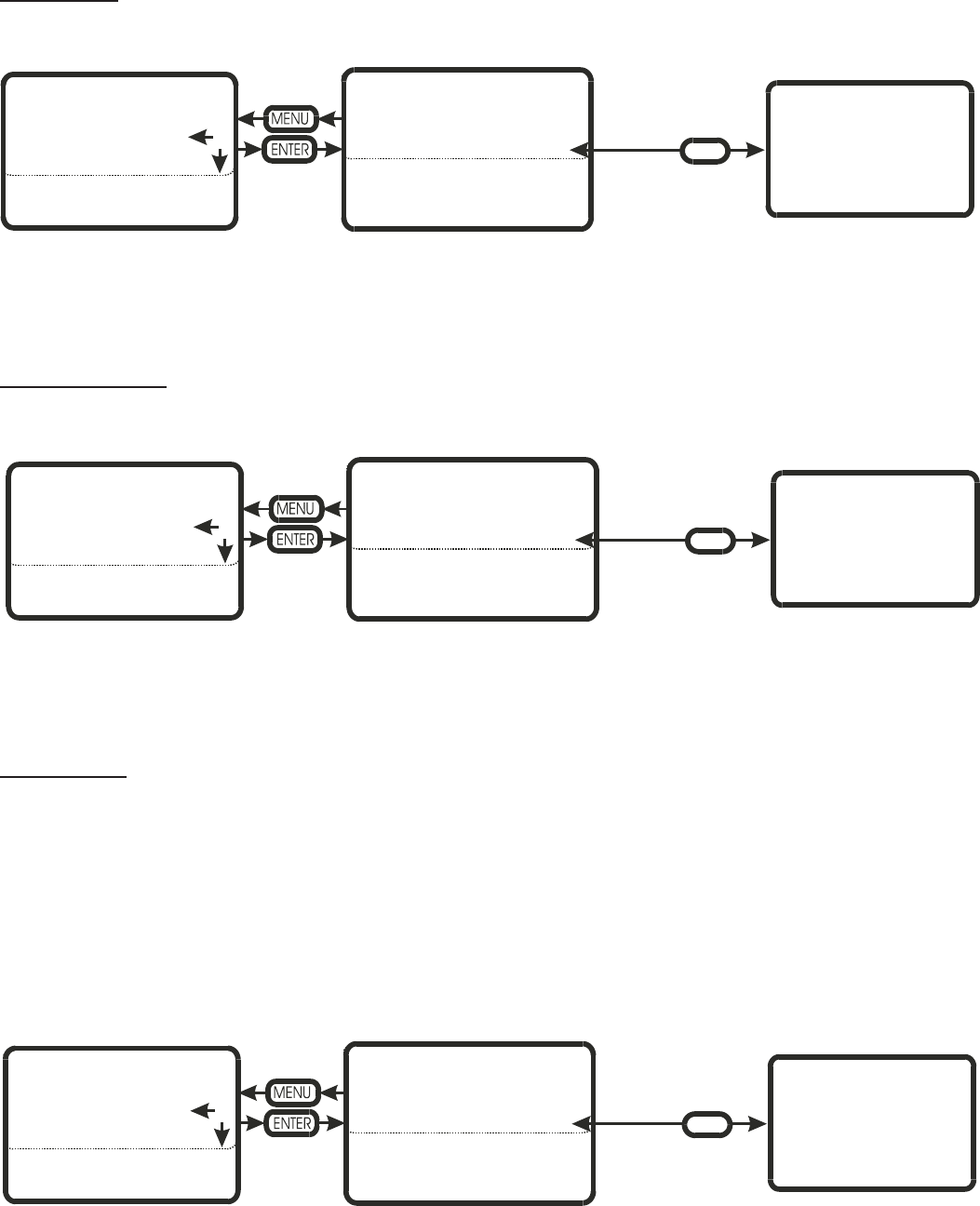
FTBD Hour
Works in conjunction with FTBD hours.
Here the user sets the time of day (24 hour format) when they want the FTBD to execute. The time can be set to
trigger the cycle during off hours, when the humidity requirements are minimal.
The time is adjusted in one-hour increments.
Blowdown Rate
This parameter adjusts the frequency of blowdown cycles.
Depending on water quality, the blowdown rate can be adjusted from 5% to 50%. The percentage is based on the
steam production rate i.e. a 10% BD rate will drain 10 kg. of water for every 100 kg. of steam produced.
The higher the mineral content of the water the higher the BD rate should be set.
Float Check
This parameter sets the time of day the controller will force a float check.
Float checks are important to ensure the water level detection system is operating correctly. The float check also
tests the fill and drain system and will report any problems detected.
To set the time of day, highlight the selection then enter the user code (0335). Press enter. Use the UP/DOWN
arrows to adjust the hours (24 hour format). Pressing enter saves the setting and indexes the display to minutes. Use
the UP/DOWN arrows to adjust the minutes. Pressing enter saves the setting and returns the user to the previous
menu.
BLOWDOWN RATE
CHANGE VALUE XX%
STEAM OUTPUT
DATE/TIME/UNITS FTBD HOURS XXX
FTBD HOUR XX
BLOWDOWN RATE XX%
FLOAT CHECK HH:MM
FILL CORRCTN XX%
DRAIN CORRCTN XX%
DRAIN COOL: ON
LANGUAGE CONTROLS
WATER MANAGEMENT
CONTROL TYPE
CAPACITY LIMIT
CALIBRATE
0335
FLOAT CHECK
CHANGE VALUE HH:MM
DATE/TIME/UNITS FTBD HOURS XXX
FTBD HOUR XX
BLOWDOWN RATE XX%
FLOAT CHECK HH:MM
FILL CORRCTN XX%
DRAIN CORRCTN XX%
DRAIN COOL: ON
LANGUAGE CONTROLS
WATER MANAGEMENT
CONTROL TYPE
CAPACITY LIMIT
CALIBRATE
0335
DRAIN COOL:
ON
OFF
SMART
DATE/TIME/UNITS FTBD HOURS XXX
FTBD HOUR XX
BLOWDOWN RATE XX%
FLOAT CHECK HH:MM
FILL CORRCTN XX%
DRAIN CORRCTN XX%
DRAIN COOL: ON
LANGUAGE CONTROLS
WATER MANAGEMENT
CONTROL TYPE
CAPACITY LIMIT
CALIBRATE
0335
- 57-
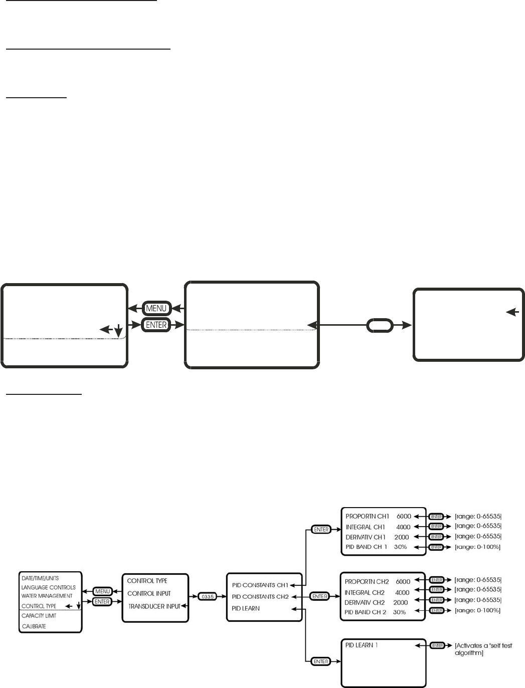
Fill CORRCTN (correction)
Used for adjusting the fill rate. Adjustments to be made under factory direction only.
Drain CORRCTN (correction)
Used for adjusting the drain rate. Adjustments to be made under factory direction only.
Drain Cool
The customer can select the type of drain water tempering they require (depending on local plumbing codes)
The customer can select ON, OFF, or SMART.
ON – whenever the drain valve is activated through software, the fill valve will automatically activate. This is the
factory default setting, but is the most wasteful of water since it will activate even if the drain water is cool.
OFF – The drain water is never tempered. This can be used where plumbing codes permit. Some process waters
are very expensive, so the customer may choose to temper the drain water through other means.
SMART – The humidifier has a tank sensor that communicates the water temperature to the controller. If the
water is hot during drain cycles the fill valve will be activated. This is the most “water smart” of the settings.
Control Input
This section is used for configuring the controller for a controller input or a transducer input.
To select control input, highlight the selection then enter the user code (0335). Press enter. Use the UP/DOWN
arrows to select control input.
The controllers dip switches then determine the type (0-10 Vdc, 0-20 mA, etc.) of control signal to process.
CONTROL TYPE
CONTROL INPUT
TRANSDUCER INPUT
DATE/TIME/UNITS CONTROL TYPE
CONTROL INPUT
TRANSDUCER INPUT
LANGUAGE CONTROLS
WATER MANAGEMENT
CONTROL TYPE
CAPACITY LIMIT
CALIBRATE
0335
-58-
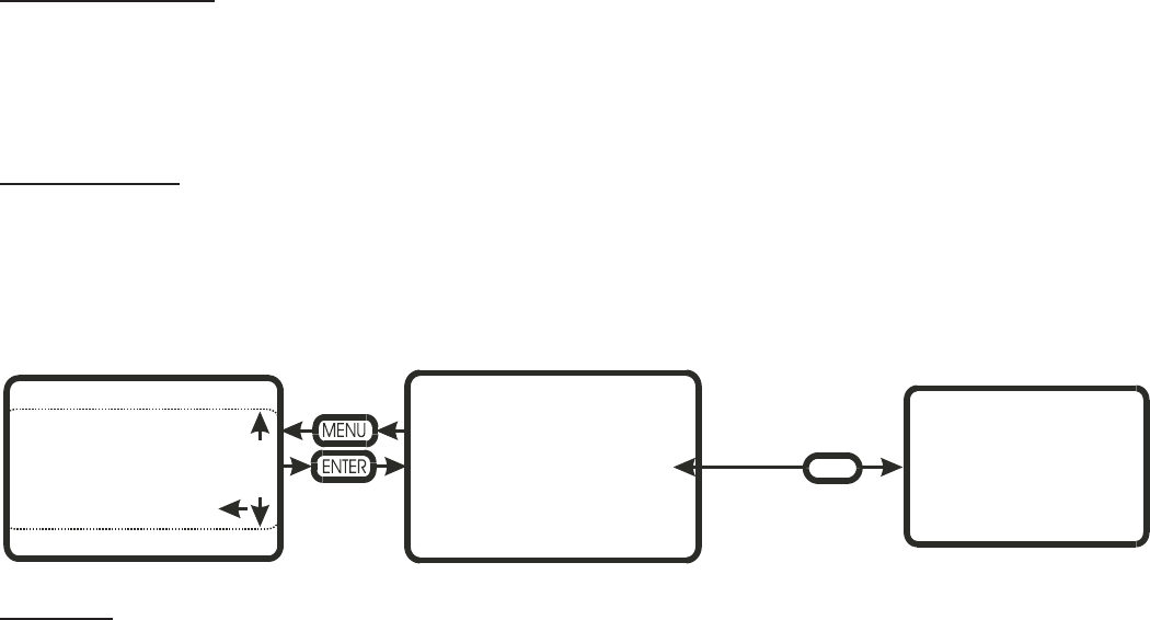
Transducer Input
This section is used to configure the controller for transducer signals
In this section you can adjust the proportional, integral and derivative constants. There is also a PID learn
algorithm which will tune the various PID constants for optimal performance.
Capacity Limit
In this section the customer can adjust the maximum output of the humidifier between 25-100%.
To adjust the maximum capacity, highlight the selection then enter the user code (0335). Press enter. Use the
UP/DOWN arrows to adjust the output between 25 and 100%.
Calibrate
This selection is used to fine-tune the operating range of the controller. Some modulation signals are not precisely
as stated e.g. a 0-10 controller could actually modulate over a 0-11 volt range.
This selection should only be used by factory-trained individuals.
DATE/TIME/UNITS
LANGUAGE CONTROLS
WATER MANAGEMENT
CONTROL TYPE
CAPCITY LIMIT
CALIBRATE
SET MAXIMUM
CAPACITY XXX%
0335
SET MAXIMUM
CAPACITY XXX%
-59-

FAULT LIST
GSTC fault
displayed
GSP fault code
displayed
Description of fault Troubleshooting
FAULT
NO BURNERS
AVAILIBLE
NBF Once the GS controller detects an ignition
module fail, it will index to the next available
ignition module. If all ignition modules have
failed or there are none available (in the case of
a 100 unit) this fault will be generated
-Check red LED’s on all modules for
flashing fault code
-Ensure there is gas supply to the
humidifier
-Ensure that the burners have not been
disabled in the software
-Consult factory
FAULT
AIR PROVING
SWITCHXOPEN
WITH
BLOWERS ACTIVE
AOF-X On startup after 3 tries if the AP switch does
not close within the proving period, this fault
will be generated
-Check that blue hoses on the Air
Proving switch have not come loose.
-Check that wires on the Air Proving
switch are on the N/O contacts
-If available, swap Air Proving switch
with another and see if the fault follows
the air proving switch, if so, replace
switch
-Consult factory
FAULT
AIR PROVING
SWITCH X
CLOSED WITH
BLOWERS
INACTIVE
ACF-X On initial startup if any of the A/P switches are
closed this fault will be generated.
-Ensure that wiring on the air proving
switchisontheN/Ocontacts
-Ensure that there is no continuity
between the switch with the wires off,
if so replace switch
-Ensure that there is not a strong
positive pressure in the room holding
the switch closed
-Consult factory
FAULT
BLOWER X
RPM HIGH
BHF-X If the blower RPM is above the RPM tolerance
for more than 10 seconds, this fault is
generated and the humidifier stops.
-Check wiring to lead blower and
ensure a good connection.
-Check lead blower for any restrictions
by testing it in the diagnostics screen.
-Consult factory
FAULT
BLOWER X
RPM LOW
BLF-X If the blower RPM is below the RPM tolerance
for more than 10 seconds, this fault is
generated and the humidifier stops
-Check wiring to blower X and ensure
a good connection.
-Check blower X for any restrictions by
testing it in the diagnostics screen.
-Consult factory
FAULT
BLOWER X
NOT OPERATIONAL
BNF-X On startup, if the blower RPM does not exceed
500 RPM within 5 seconds or if during
operation, the RPM drops below 500 RPM for
more than 5 seconds this fault is generated
-Ensure there is power to the blower
and that all wires are making a proper
connection.
-Consult factory
FAULT
ILLEGAL GAS
VALVE
BURNER X
GVF-X If the controller detects that a gas valve has
activated at a time it should not this fault is
Generated.
-Ensure that the ignition module is not
miswired or that the module is not
faulty by swapping it with a known
good one. If the problem follows the
ignition module, replace the module
-Consult factory
-60-

FAULT LIST
FAULT
GAS RE-IGNITION
BURNER X
GIF-X Following an ignition module fault if the
modules gas valve activates this fault will be
generated.
-Ensure that the ignition module is not
miswired or that the module is not
faulty by swapping it with a known
good one. If the problem follows the
ignition module, replace the module
-Consult factory
FAULT
DRAIN NOT
WORKING
DRAIN IS BLOCKED
DBF There are many time windows in the GS
software. If, during a drain cycle, the time
window for the water level to drop is exceeded,
this fault is generated
-Ensure that pump is being energized
-Check for blockage in all aspects of
the drain system
-Float board defective
-Consult factory
FAULT
FLOAT CHECK
FCF Once every 24 hours (provided the unit is
powered and in an operating or standby
condition) the controller will test the water
level detection circuit. If the test fails this fault
is displayed
-Ensure the proper operation of the fill
valve and drain valve via the
diagnostics screen
-Float board is defective
-Consult factory
FAULT
ILLEGAL FLOAT
COMBINATION
WLF If the controller detects two or more float level
readings, which are not expected (ex. Switch 1
and 3 ON or switch 1, 2, and 3 ON) this fault
will be recorded.
-Miswired float board
-Defective float board
-Consult factory
FAULT
FILL VAVLE ON
DETECTION
INCONSISTENT
FDF The controller monitors the water level as it
fills and drains. It expects to see the levels
increase logically (1-2-3-4-5). If the water level
increases and jumps a step (1-2-4-5) this fault
will be generated. The same holds for water
level decreasing.
-Float board defective
-Contact agent for replacement float
board
FAULT
KEEP WARM TIME
OUT
TOO LONG TO
HEAT
KWF During a keep warn cycle, if the tank
temperature sensor does not open within a
certain time window, this fault is generated.
-Ensure that the tank temperature
sensor is connected
-Defective tank temperature switch
-Contact agent for replacement switch.
FAULT
STACK OVER
TEMP.
SWITCH TRIPPED
OTF If input TB5, # 4 on the logic board goes low
(no 24 Vac detected) this fault will be
generated. This could indicate either the tank
over temperature switch has opened or the
stack over temperature switch has opened.
-Do not operate and consult the factory
FAULT
MAINTENANCE
TIME
HAS ELAPSED
HMF In the user menu the user sets the maintenance
time. Once this time expires a warning is
displayed. 72 hours later the warning changes
to this fault. The maintenance time is measured
in weighted operational hours.
With switch 5, #4 deactivated, this fault is
enabled
-Perform tank cleaning and all other
maintenance requirements outlined in
the manual.
FAULT
WATER FILL FAIL
FTF Fill time-out fault during fill process. The GS
software monitors the changes in water level
during filling sequence. If ware level changes
do not occur within an expected time interval,
this fault will be generated.
-Verify water supply is open
-Verify adequate water supply to unit
(30-80psi, 10L/min, minimum ½” dia.
Line size)
-Verify wire harness and connection
between float chamber and I/O board
(TB)
-61-

WARNING LIST
GSTC Warning
displayed
GSP warning
displayed
Description of warning: Troubleshooting
WARNING
IGNITION MODULE X
FAIL
IMW-X Once the controller activates an ignition module, it will
allow 4 minutes for the gas valve to activate. After the trial
period, if the gas valve has not activated, a fault will be
generated. The module will be locked out and the next
burner will be indexed.
SEE FAULT LIST
WARNING
AIR PROVING SWITCH X
OPEN WITH
BLOWERS ACTIVE
APW-X Should the air proving switch open while the unit is
operating this warning is generated. The controller shuts
down and retries. There are no limits to the amount of times
this warning is generated.
SEE FAULT LIST
WARNING
AIR PROVING SWITCH X
OPEN WITH
BLOWERS ACTIVE
AOW-X On startup if the AP switch does not close within the proving
period. After 3 tries, a fault will be generated.
SEE FAULT LIST
WARNING
BLOWER X
RPM HIGH
BHW-X If a blower RPM is above the RPM tolerance limit this
warning is generated. If it is above the RPM tolerance limit
for more than 10 seconds a fault will be generated.
SEE FAULT LIST
WARNING
BLOWER X
RPM LOW
BLW-X If a blower RPM is below the RPM tolerance limit this
warning is generated. If it is below the RPM tolerance limit
for more than 10 seconds a fault will be generated.
SEE FAULT LIST
WARNING
MAINTENANCE TIME
HAS ELAPSED
HMW In the user menu the user sets the maintenance time. Once
this time expires this warning is displayed. The maintenance
time is measured in weighted operational hours.
With switch 5, #4 activated, this warning will remain until
the warning is reset in the User level
SEE FAULT LIST
WARNING
Too LONG TO FILL
UNW-6 Low water level has not been reached within expected time
interval during initial fill sequence. Unit will continue filling
while warning is displayed. A Water Fill Fail fault will be
generated if the low water level is not reached after an
additional length of time.
SEE FAULT LIST
WARNING
KEEP WARM ACTIVE
SYSTEM DEMAND
ACTIVATED AT 75%
UNW-C Keep warm feature has initiated combustion sequence at
75% output. This occurs when keep warm feature has been
activated via dip-switch settings, the system demand is
below minimum and the tank temperature sensor is
registering cold (open contacts).
-Warning message
will stop being
displayed once tank
temperature sensor
indicates water is
warm
-Keep warm feature
can be disabled using
dip-switch settings
-62-
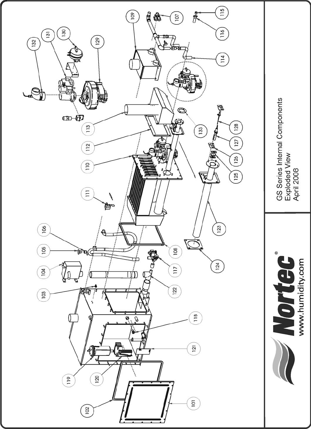
-63-

GS Series Internal Components Spare Parts
-64-
Number Description Part # GS 100 GS 200 GS 300 GS 400 GS 500 GS 600
101 Cover Plate, Clean-Out Port 2523457 1 1 2 2 3 3
102 Gasket, Tank Cover Plate 2524361 1 1 2 2 3 3
103 Secondary Safety Switch 1504832 1 1 1 1 1 1
104 Fill Box 2526152 1 1 1 1 1 1
105 Vacuum Break Valve ½” npt 1505959 1 1 1 1 1 1
106 P-Trap 2526521
107 Dual Fill Valve 10.0 l/min & 0.35 l/min 1505759 1 1 1 1 1 1
108 Heat Exchanger Gasket
Single 2524405 1
Dual 2524403 1 2 2 3 3
109 Direct Vent Air Manifold
GS 100 1506140 1
GS 200 1506141 1
GS 300/400 1506142 1 1
GS 500/600 1506143 1 1
110 Heat Exchanger Replacement Kit
Mini 2528422 1
Single 2528423 1 1
Dual 2528424 1 1 2 2 3
111 Stack High Limit Switch 1506745 1 1 1 1 1 1
112 Exhaust Manifold Gasket
Single 1505973 1
Dual 1505942 1 2 2 3 3
113 Exhaust Manifold
GS 100 1505875 1
GS 200 1505861 1
GS 300/400 1505843 1 1
GS 500/600 1505828 1 1
114 Flexible Gas Hose with fittings 1505960 1 2 3 4 5 6
115 Auxillary Drain Plug 1507043 1 1 1 1 1 1
116 Auxillary Drain Termination 1506925 1 1 1 1 1 1
117 Drain Pump 24v 60 hz 1502644 1 1 1 1 1 1
118 Tank Thermal Sensor 1506026 1 1 1 1 1 1
119 Float Chamber 1115933 1 1 1 1 1 1
120 Float Chamber Mounting Bracket 1113777 1 1 1 1 1 1
121 Float Board 2521137 1 1 1 1 1 1
122 Lower Mixing Box 1506749 1 1 1 1 1 1
123 Replacement Burner Ass’y
110-120V Models 2528416 1 2 3 4 5 6
208-240V Models 1507669 1 2 3 4 5 6
124 Burner Plate Gasket 1505936 1 2 3 4 5 6
125 Sight Port Replacement Kit 2528417 1 2 3 4 5 6

-65-
GS Series Internal Components Spare Parts - continued
Number Description Part # GS 100 GS 200 GS 300 GS 400 GS 500 GS 600
126 Igniter / flame sensor gasket 1506892 1 2 3 4 5 6
127 Hot Surface Igniter Replacement kit
110-120V Models 2528418 1 2 3 4 5 6
208-240V Models 1507695 1 2 3 4 5 6
128 Flame Sensor Replacement Kit 1507694 1 2 3 4 5 6
Igniter / flame Sensor Replacement Kit
110-120V Models 2528420 1 2 3 4 5 6
208-240V Models 1507712 1 2 3 4 5 6
129 Combustion Blower
110-120V Models 2524360 1 2 3 4 5 6
208-240V Models 1502289 1 2 3 4 5 6
130 Air Proving Switch 1504175 1 2 3 4 5 6
131 Gas Valve Assembly
Natural Gas 1507713 1 2 3 4 5 6
Propane 1507714 1 2 3 4 5 6
132 Elbow Assembly for Air Intake 1504204 1 2 3 4 5 6
133 Burner / Blower Gasket 1708208 1 2 3 4 5 6
Not
Shown Bracket, Fan Board Mount 1505899 1 1 2 2 3 3
Not
Shown Fan Board 1505689 1 1 2 2 3 3
Not
Shown Igniter Jump Start Module 1506793 1 2 3 4 5 6
Not
Shown Hose Replacement Kit 1507696 1 1 1 1 1 1
Not
Shown Flexible hose for Direct Vent 1502148 1 2 3 4 5 6
Not
Shown ¼” Tube for Air Proving (per inch) 1605227 Order (by foot) as Required
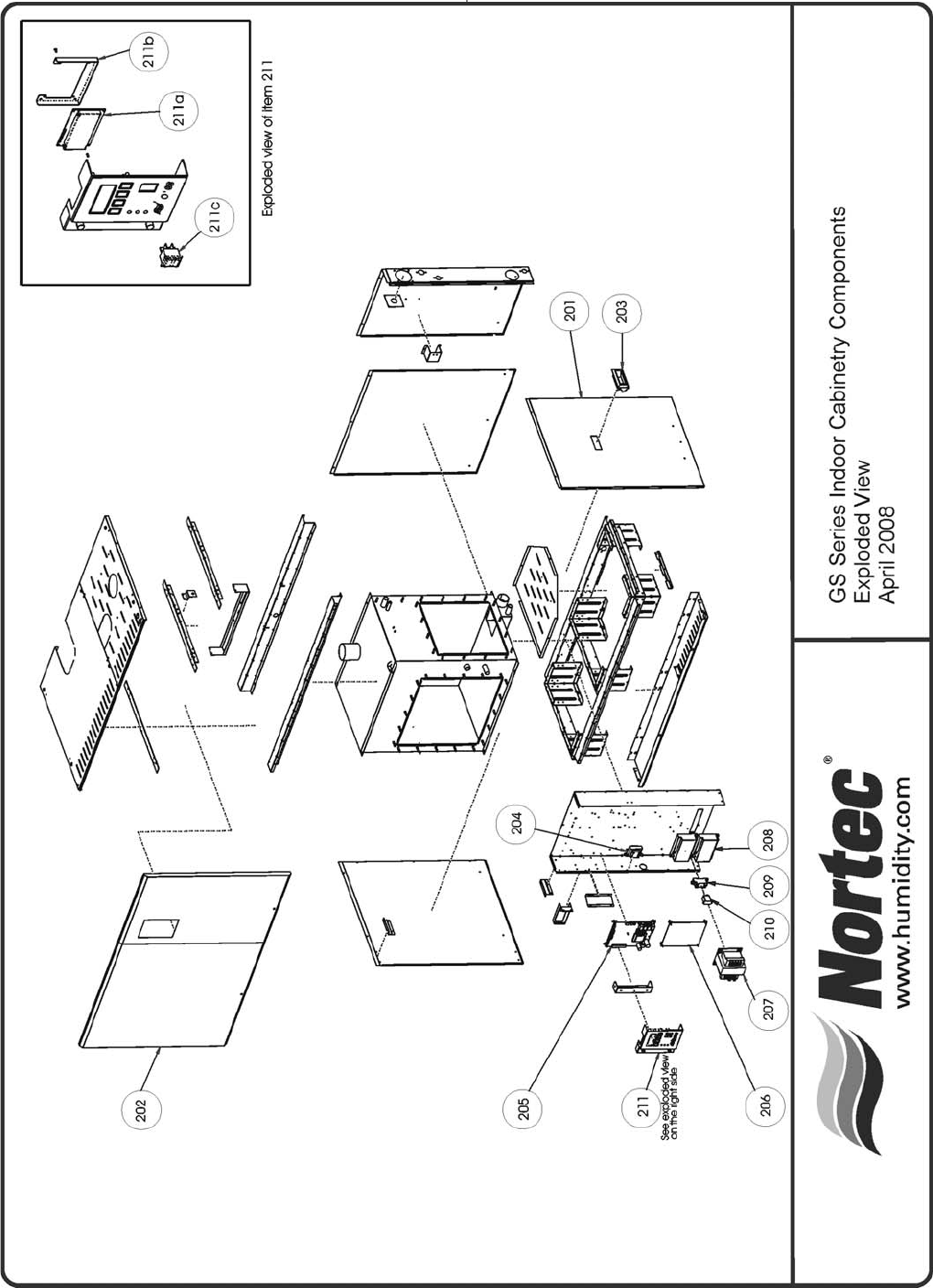
-66-

-67-
GS Series Indoor Cabinetry Spare Parts
Number Description Part # GS 100 GS 200 GS 300 GS 400 GS 500 GS 600
201 Service Door Assembly
Mini 2524439 1
Single 2524440 1
Double 2524441 1 1
Triple 2524458 1 1
202 Fron t Door Assembly 2528421 1 1 1 1 1 1
203 Recessed Handle 2523444 1 1 1 1 2 2
204 Transformer 24/16V 15VA 50/60 hz 1505760 1 1 1 1 1 1
205 Logic Control Board 1505762 1 1 1 1 1 1
206 I/O Board 1504760 1 1 1 1 1 1
207 Primary Transformer
110-120 V Models 1504859 1 1 1 1 1 1
208-240V Models 15067619 1 1 1 1 1 1
Fuse for Primary transformer, 6.25 AMP 1505020 1 1 1 1 1 1
208 Ignition Control Module
110-120V Models 2525914 1 2 3 4 5 6
208-240V Models 1505987 1 2 3 4 5 6
209 Relay Mount Socket 1703250 1 1 1 1 1 1
210 Blower Relay 1453020 1 1 1 1 1 1
Not
Shown Slotted wire duct 1506041 Order by Length Required
211a LCD Display Assembly 1507741 1 1 1 1 1 1
211b LCD Mounting Bracket 1506951 1 1 1 1 1 1
211c On/Off Drain Switch 1453001 1 1 1 1 1 1
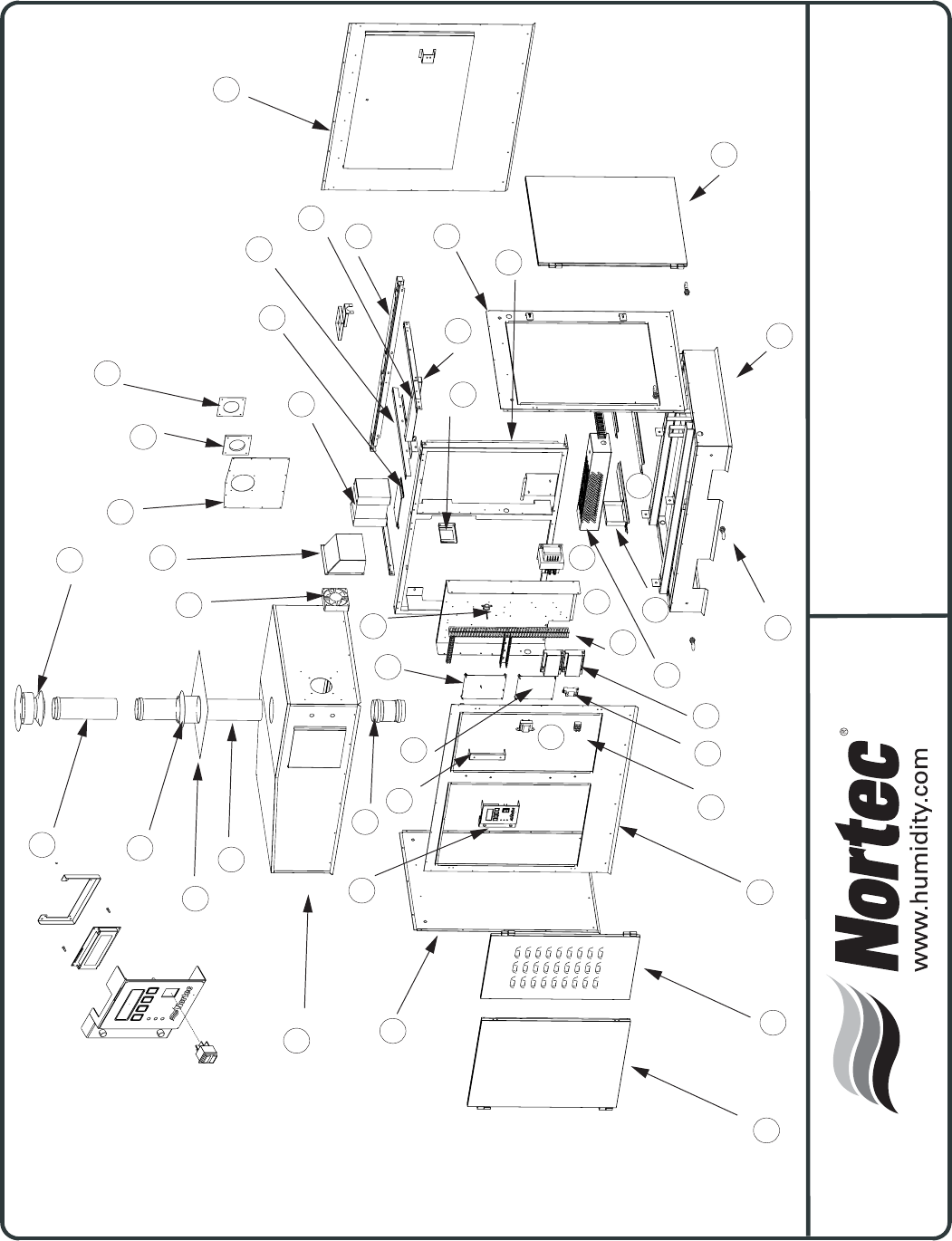
-68-
16
19
20
21
22
23
24
25
26
27
28
29
30
31
32
34
33
35
36
37
38
39
40
41
43
44
2
11
7
42
6
8
9
12
13
14
1
15
318
17
4
10
5
GS Series Outdoor Cabinetry
Exploded View

-69-
Description Part # GS 100 GS 200 GS 300 GS 400 GS 500 GS 600
1Transformer24/16V15VA 1505760111111
2Transformer208-24Vac250VA 1506719111111
Fuse6.25Ampfor208Vtransformer1505020111111
3aLCDDisplayAssembly 1507741111111
3bLCDMountingBracket 1506951111111
3cOn-Off-DrainSwitch 1453001111111
4LogicControlBoard 1505762111111
5I/OBoard 1504760111111
6IgnitionControlModule 1505987123456
7 Slotted wire duct 1506041
8RelayMountSocket 1703250111111
9BlowerRelay 1453020111111
10Thermostat,On/Off,80F 1508042111111
11ElectricalCabinet 1506989111111
12FrontPanel 1507783111111
13AccessDoor,Electronics 1507801111111
14AccessDoor,Tank 1507800111111
15 Left Panel Mini 1508096 1
Single 1508095 1
Double 1507861 1 1
Triple 1507804 1 1
16 Top Cap Assembly Mini 1508100 1
Single 1508099 1
Double 1507863 1 1
Triple 1507806 1 1
17DisplayBracketHolder 1506950111111
18 Female to Female Coupling 3" Dia. 1508136 1
4" Dia 1508135 1
5" Dia 1507886 1 1
6" dia 1507880 1 1
19 Vent Pipe, 24" Long 3" Dia 1508132 1
4" Dia 1508131 1
5" Dia 1507888 1 1
6" dia 1507882 1 1
20 Chimney Flashing, for 3" vent pipe 1508138 1
for 4" vent pipe 1508137 1
for 5" vent pipe 1507885 1 1
for 6" vent pipe 1508150 1 1
21 Storm Collar, for 3" vent pipe 1508140 1
for 4" vent pipe 1508139 1
for 5" vent pipe 1507890 1 1
for 6" vent pipe 1507884 1 1
22 Vent Pipe, 12" Long 3" Dia 1508134 1
4" Dia 1508133 1
5" Dia 1507884 1 1
6" dia 1507881 1 1
23 Rain Cap Mini 1508130 1
Single 1508129 1
Double 1507889 1 1
Triple 1507883 1 1
24CoolingFan 1507891111111
order by length required
GS Outdoor Spare Parts List

-70-
25 Fan Hood 1507811 1 1 1 1 1 1
26 Cover Plate Top Panel 1508109 1 1 1 1 1 1
27 Gasket, Steamline 100 1508105 1
200/300 1507872 1 1
400/500/600 1507871 1 1 1
28 Cover Plate Steam Line 100 1508106 1
200/300 1507870 1 1
400/500/600 1507810 1 1 1
29 Step-up transformer (120/240V option) 1508167 1 1 1 1 1 1
30 Mounting bracket, step-up transformer 1507759 1 1 1 1 1 1
31 Mid Cross Member Mini 1506958 1
Single 1506978 1
Double 1506983 1 1
Triple 1506972 1 1
32 Gas Line Bracket 1506960 1 1 2 2 2 2
33 Rear Frame Element 1506963 1 1 1 1 1 1
34 Rear Panel 1507785 1 1 1 1 1 1
35 Cross Member Mini 1506957 2
Single 1506979 2
Double 1506981 2 2
Triple 1506971 2 2
36 Mounting bracket, float chamber 1508114 1 1 1 1 1 1
37 Front Frame 1506959 1 1 1 1 1 1
38 Right Panel Mini 1508087 1
Single 1508097 1
Double 1507862 1 1
Triple 1507803 1 1
39 Access Door, Side 1507801 1
1507800 1 2 2
1507860 1 1
40 Base Assembly Mini 1508123 1
Single 1508122 1
Double 1508017 1 1
Triple 1508018 1 1
41 Lifting Lug 1507901 4 4 4 4 4 4
42 Pump House Heater 500 watts 1508039 1 1 2 2 3 3
43 Mounting Bar Pump House Heater, Mini 1508113 2
Single 1508112 2
Double 1508111 2 2
Triple 1508164 2 2
44 Strapping, Pump House Heater 1508110 1 1 2 2 3 3
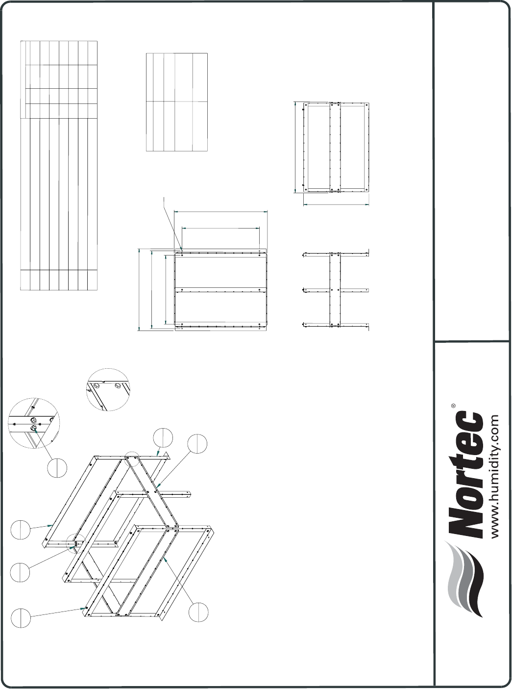
GS Stand Assembly Instructions
150-7308
06/26/2003
43.1in
109.4cm
43.1in
109.4cm
35.7in
90.7cm
30.2in
76.7cm
O0.5in
1.3cm
DETAIL B
DETAIL A
A
B
FLOOR STAND, ASSEMBLY INSTRUCTIONS, GS/SE
ASSEMBLY INSTRUCTIONS
1. UNPACK STAND AND CHECK THAT ALL PIECES ARE PRESENT AND UNDAMAGED.
2. ASSEMBLE STAND TO CONFIGURATION SHOWN ON SHEET 1. HAND TIGHTEN ALL
BOLTS ONLY.
3. HOIST HUMIDIFIER UP ABOVE THE FLOOR A MINIMUM OF 32 IN (812.8 MM).
4. POSITION STAND BELLOW THE LEGS OF THE HUMIDIFIER. ALIGN HUMIDIFIER AND
STAND SO THAT HOLES IN THE HUMIDIFIER BASE ALIGN WITH HOLES IN STAND.
5. LOWER HUMIDIFIER 1/4" ABOVE STAND TO ALIGN WITH NEAREST HOLE.
6. FASTEN STAND TO HUMIDIFIER USING THE BOLTS, LOCKWASHERS AND NUTS
PROVIDED.
7. TIGHTEN NUT AND BOLT PAIRS TO 200 IN-LB ((2.3 Kg-m) OR UNTILL SECURE.
8. LOWER ENTIRE ASSEMBLY TO FLOOR AND ENSURE THAT IT IS STABLE.
9. SHIMMING OF THE FLOOR BELLOW THE LEGS OF THE STANDS MAY BE NECESSARY
TO ENSURE BALANCE OF THE HUMIDIIFER.
10. THE STAND MAY BE PERMENANTLY FASTENED TO THE FLOOR VIA THE HOLES IN
THE LEG SUPPORT PLATES.
GS100, GH2E40 14.85in (37.7 cm)
GS200, GH2E80 21.15in (53.7 cm)
GS300, GS400, 36.7in (93.3 cm)
GH2E120, GH2E160
GS500, GS600, 52.35in (133 cm)
GH2E200, GH2E240
UNIT SIZE DIMENSION A
REV A
2525888
5
36
2
5
1
6
6
36
3
2
7
36
4
2
A
A + 2in (5.1 cm)
THE MIDDLE SECTION IS USED ONLY FOR GS300/400 AND GS500/600
(SHOWN THE STAND FOR GS300/400)
A - 4.2in (10.6 cm)
28
28
28
28
28
28
2
2
Nut, 3/8-16 UNC, SST
7
Lock washer, 0.375
6
BOLT, 3/8-16UNC X 3/4LG
5
BRACE, FLOOR STAND, GS-SE, B STYLE
4
BRACE, COMMON, FLOOR STAND, GS/SE, B STYLE
3
PLATE, CARRIER, FLOOR STAND, GS/SE, B STYLE
2
LEG, FLOOR STAND, GS/SE, B STYLE
1
Description
Item
22
4
4
44
36
36
36
2
2
5
6
36
36
36
2
2
5
6
Qty
GS100 GS200 GS300/400 GS500/600
-71 -
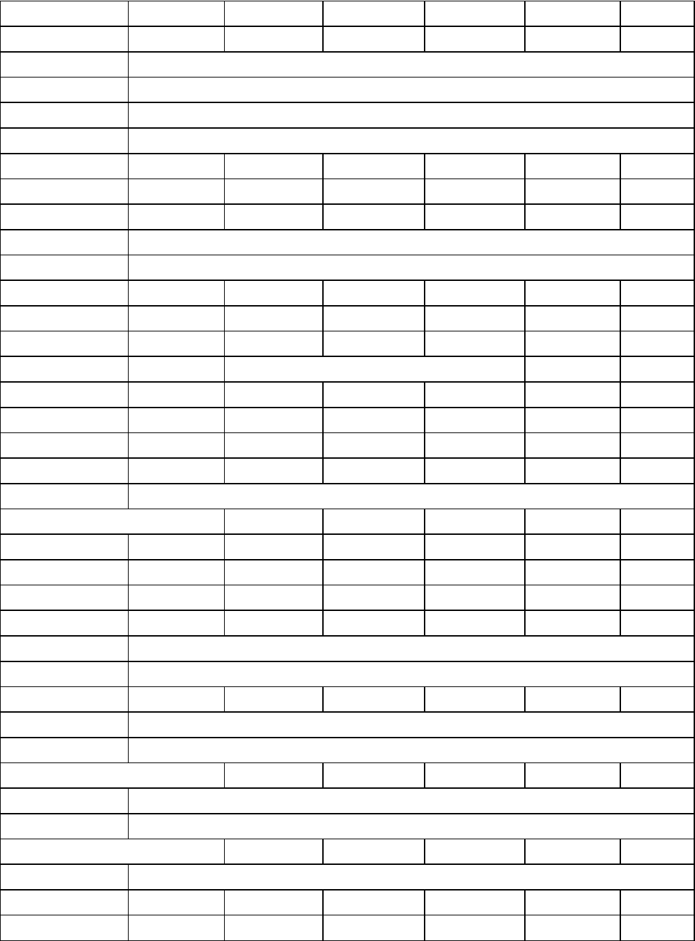
-72-
Item GS 100 GS 200 GS 300 GS 400 GS 500 GS 600
Gas Pressure
Natural Gas min "wc/mbar
Natural Gas max "wc/mbar
Propane min
Propane max
Min free air opening in/cm 13/33 23/58 35/89 47/119 59/150 71/180
Input BTU's
Max 140,000 280,000 420,000 560,000 700,000 840,000
Min GSTC 45,000
Direct vent min 60,000
Gas Piping Size in/cm 1/2/1.3 3/4/1.9 1/2.5 1/2.5 1.25/3.2 1.25/3.2
"BH" Vent XX X XXX
"B" Vent XX X XXX
"BH" Exhaust Piping in/cm 3/7.6 4/10.2 5/12.7 5/12.7 6/15.2 6/15.2
4/10.2 5/12.7 7/17.8 7/17.8 8/20.3 8/20.3
Appliance Category I or III I or III I or III I or III I or III I or III
Full Weight In lbs./kg 416/188 588/266 954/432 974/441 1340/607 1360616
Empty Weight In lbs./kg 266/120 354/160 485/217 529/239 659/298 703/318
User level password
Water consumption (25% bd)
Gallons/litres 433/1639 866/3278 1300/4921 1733/6560 2166/8199 2600/9842
Tank Water Volume
Gallons/litres 18/71 29/111 58/221 55/210 84/320 81/309
Fill valve flow rates
To tank: Gallons/litres
To float chamber: Gallons/litres
Supply water pressure
Min. psi/kpa
Max. psi/kpa
Drain rate (includes D.W.C)
Gallons/Litres per minute
Min drain pipe size in/cm
Power supply requirements
120 volts a/c
208-240 volts a/c 1PH XX X XXX
Steam Outlet size in/cm 1.75/4.4 3/7.6 3/7.6 4/10.2 4/10.2 4/10.2
0.09/0.35
5.2/20
1 to 1.5 / 2.5 to 3.8 OD or larger
Transformer Required
30/206
80/551
0335
2.64/10
14/34
9/22
10/23
GS Quick Reference
5/14

LIMITED WARRANTY
Walter Meier Inc. and/or Walter Meier Ltd. (hereinafter collectively referred to as THE COMPANY),
warrant for a period of two years from date of shipment, that THE COMPANY's manufactured and
assembled products, not otherwise expressly warranted, are free from defects in material and
workmanship. No warranty is made against corrosion, deterioration, or suitability of substituted materials
used as a result of compliance with government regulations.
THE COMPANY's obligations and liabilities under this warranty are limited to furnishing replacement
parts to the customer, F.O.B. THE COMPANY's factory, providing the defective part(s) is returned freight
prepaid by the customer. Parts used for repairs are warranted for the balance of the term of the warranty
on the original humidifier or 90 days, whichever is longer.
The warranties set forth herein are in lieu of all other warranties expressed or implied by law. No
liability whatsoever shall be attached to THE COMPANY until said products have been paid for in full and
then said liability shall be limited to the original purchase price for the product. Any further warranty must
be in writing, signed by an officer of THE COMPANY.
THE COMPANY's limited warranty on accessories, not of Walter Meier’s manufacture, such as
controls, humidistats, pumps, etc. is limited to the warranty of the original equipment manufacturer from
date of original shipment of humidifier.
THE COMPANY makes no warranty and assumes no liability unless the equipment is installed in
strict accordance with a copy of the catalog and installation manual in effect at the date of purchase and
by a contractor approved by THE COMPANY to install such equipment.
THE COMPANY makes no warranty and assumes no liability whatsoever for consequential damage
or damage resulting directly from misapplication, incorrect sizing or lack of proper MAINTENANCE of the
equipment.
THE COMPANY retains the right to change the design, specification and performance criteria of its
products without notice or obligation.

PRINTED IN CANADA
Walter Meier (Climate USA) Inc.
826 Proctor Avenue, Ogdensburg, New York 13669
Walter Meier (Climate Canada) Ltd.
2740 Fenton Road, Ottawa, Ontario K1T3T7
Tel: 866 NORTEC 1 Fax: 613 822 7964
northamerica.climate@waltermeier.com www.humidity.com
