Nortek Security and Control 2GIG SP2GC3 Wireless Touch Screen User Manual

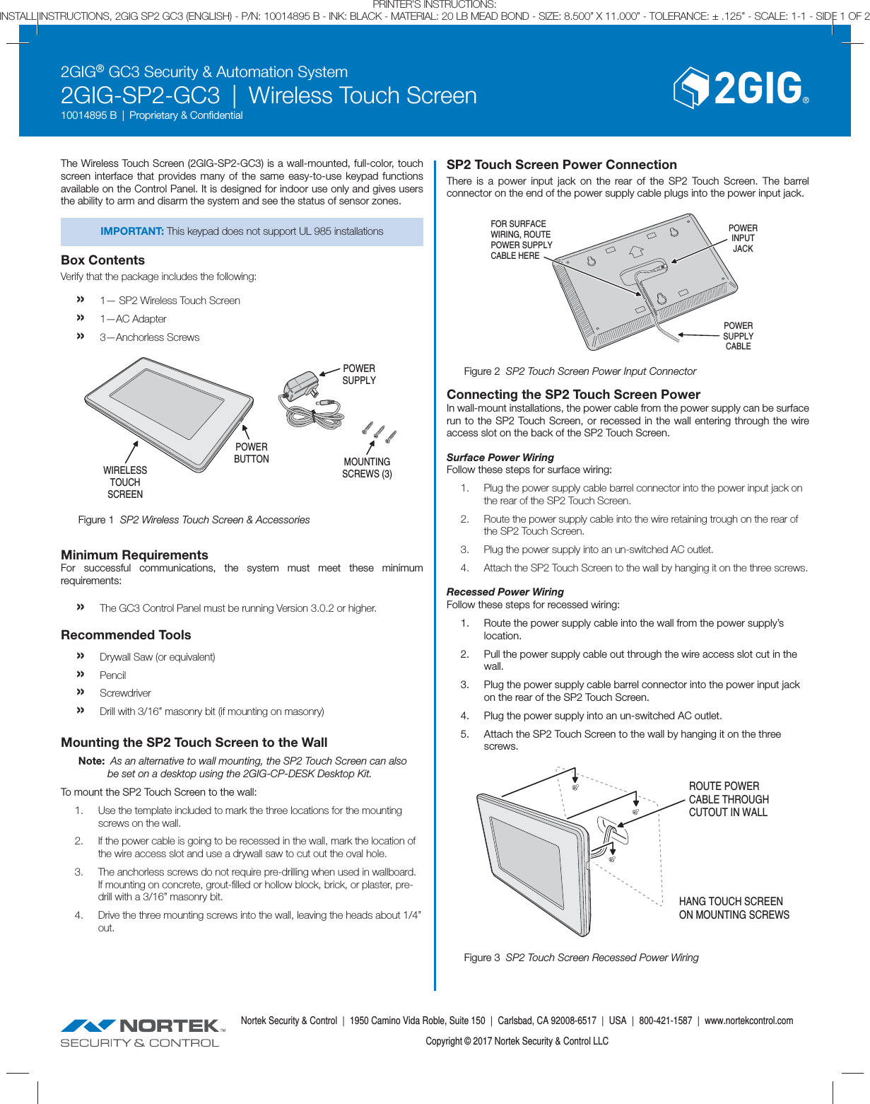
2GIG Technologies, Inc. Wireless Touch Screen

User Manual

2GIG® GC3 Security & Automation System2GIG-SP2-GC3  |  Wireless Touch Screen10014895 B  |  Proprietary & Confi dentialNortek Security & Control  |  1950 Camino Vida Roble, Suite 150  |  Carlsbad, CA 92008-6517  |  USA  |  800-421-1587  |  www.nortekcontrol.comCopyright © 2017 Nortek Security & Control LLCPRINTER’S INSTRUCTIONS:INSTALL INSTRUCTIONS, 2GIG SP2 GC3 (ENGLISH) - P/N: 10014895 B - INK: BLACK - MATERIAL: 20 LB MEAD BOND - SIZE: 8.500” X 11.000” - TOLERANCE: ± .125” - SCALE: 1-1 - SIDE 1 OF 2The Wireless Touch Screen (2GIG-SP2-GC3) is a wall-mounted, full-color, touch screen interface that provides many of the same easy-to-use keypad functions available on the Control Panel. It is designed for indoor use only and gives users the ability to arm and disarm the system and see the status of sensor zones.IMPORTANT: This keypad does not support UL 985 installationsBox ContentsVerify that the package includes the following:» 1— SP2 Wireless Touch Screen»  1—AC Adapter»  3—Anchorless ScrewsMinimum RequirementsFor successful communications, the system must meet these minimum requirements:» The GC3 Control Panel must be running Version 3.0.2 or higher.Recommended Tools» Drywall Saw (or equivalent)» Pencil» Screwdriver» Drill with 3/16” masonry bit (if mounting on masonry)Mounting the SP2 Touch Screen to the WallNote:  As an alternative to wall mounting, the SP2 Touch Screen can also be set on a desktop using the 2GIG-CP-DESK Desktop Kit.To mount the SP2 Touch Screen to the wall:1.  Use the template included to mark the three locations for the mounting screws on the wall.2.  If the power cable is going to be recessed in the wall, mark the location of the wire access slot and use a drywall saw to cut out the oval hole.3.  The anchorless screws do not require pre-drilling when used in wallboard. If mounting on concrete, grout-fi lled or hollow block, brick, or plaster, pre-drill with a 3/16” masonry bit.4.  Drive the three mounting screws into the wall, leaving the heads about 1/4” out.SP2 Touch Screen Power ConnectionThere is a power input jack on the rear of the SP2 Touch Screen. The barrel connector on the end of the power supply cable plugs into the power input jack.POWERSUPPLYCABLEPOWERINPUTJACKFOR SURFACEWIRING, ROUTEPOWER SUPPLYCABLE HEREConnecting the SP2 Touch Screen PowerIn wall-mount installations, the power cable from the power supply can be surface run to the SP2 Touch Screen, or recessed in the wall entering through the wire access slot on the back of the SP2 Touch Screen.Surface Power WiringFollow these steps for surface wiring:1.  Plug the power supply cable barrel connector into the power input jack on the rear of the SP2 Touch Screen.2.  Route the power supply cable into the wire retaining trough on the rear of the SP2 Touch Screen.3.  Plug the power supply into an un-switched AC outlet.4.  Attach the SP2 Touch Screen to the wall by hanging it on the three screws.Recessed Power WiringFollow these steps for recessed wiring:1.  Route the power supply cable into the wall from the power supply’s location.2.  Pull the power supply cable out through the wire access slot cut in the wall.3.  Plug the power supply cable barrel connector into the power input jack on the rear of the SP2 Touch Screen.4.  Plug the power supply into an un-switched AC outlet.5.  Attach the SP2 Touch Screen to the wall by hanging it on the three screws.ROUTE POWERCABLE THROUGHCUTOUT IN WALLHANG TOUCH SCREENON MOUNTING SCREWSFigure 3  SP2 Touch Screen Recessed Power WiringFigure 2  SP2 Touch Screen Power Input ConnectorPOWERBUTTON MOUNTINGSCREWS (3)POWERSUPPLYWIRELESSTOUCHSCREENFigure 1  SP2 Wireless Touch Screen & Accessories
2GIG® GC3 Security & Automation System2GIG-SP2-GC3  |  Wireless Touch Screen10014895 B  |  Proprietary & Confi dentialNortek Security & Control  |  1950 Camino Vida Roble, Suite 150  |  Carlsbad, CA 92008-6517  |  USA  |  800-421-1587  |  www.nortekcontrol.comCopyright © 2017 Nortek Security & Control LLCPRINTER’S INSTRUCTIONS:INSTALL INSTRUCTIONS, 2GIG SP2 GC3 (ENGLISH) - P/N: 10014895 B - INK: BLACK - MATERIAL: 20 LB MEAD BOND - SIZE: 8.500” X 11.000” - TOLERANCE: ± .125” - SCALE: 1-1 - SIDE 2 OF 2Pair the SP2 Touch ScreenAfter mounting and powering the SP2 Touch Screen, it will need to be setup and paired with the GC3 Control Panel. The SP2 Touch Screen pairs through a network connection to the Control Panel. The network connection can be through a local wireless Wi-Fi network or through Access Point capability directly to the GC3 Control Panel. Up to four SP2 Touch Screens can be paired with a GC3 Control Panel. Refer to: “Programming Sensors & Peripherals” in the 2GIG GC3 Security & Automation System Installation & Programming Guide.To power up the unit, press the power button on the top right side of the SP2 Touch Screen. The message “This Device is not Paired with a Control Panel” will display. On the SP2 Touch Screen, choose to connect through the local Wi-Fi network, then enter the password for the network. Proceed with pairing.Specifi cationsItem DescriptionDimensions (L x H x D) 8.875” x 5.625” x 1.000”(22.54 x 14.29 x 2.54 cm)Weight 1 lb. (0.45 kg)Housing Material ABS PlasticColor WhiteOperating Temperature 32° – 120° F (0°  – 49° C)Relative Humidity 5-95% Non-condensingOperating Voltage 5 VDCCertifi cation FCC, Industry CanadaFCC & IC NoticeThis device complies with Part 15 of the FCC Rules and Industry Canada license exempt standard(s). Operation is subject to the following two conditions:(1)  This device may not cause harmful interference, and(2)  This device must accept any interference received, including interference received that may cause undesired operation.Le présent appareil est conforme aux CNR d’Industrie Canada applicables aux appareils radio exempts de licence. L’exploitation est autorisée aux deux conditions suivantes:(1)  l’appareil ne doit pas produire de brouillage, et(2)  l’utilisateur de l’appareil doit accepter tout brouillage radioélectrique subi, même si le brouillage est susceptible d’en compromettre le fonctionnement.This Class B digital apparatus complies with Canadian ICES-003Cet appareil numérique de la classe B est conforme à la norme NMB-003 du Canada.This equipment has been tested and found to comply with the limits for a Class B digital device, pursuant to Part 15 of the FCC Rules. These limits are designed to provide reasonable protection against harmful interference in a residential installation.This equipment generates, uses, and can radiate radio frequency energy and, if not installed and used in accordance with the instructions may cause harmful interference to radio communications. However, there is no guarantee that interference will not occur in a particular installation. If this equipment does cause harmful interference to radio or television reception, which can be determined by turning the equipment off and on, the user is encouraged to try to correct the interference by one or more of the following measures:» Reorient or relocate the receiving antenna.» Increase the separation between the equipment and receiver.» Connect the equipment into an outlet on a circuit different from that to which the receiver is connected.» Consult the dealer or an experienced radio/TV technician to help.WARNING:Changes or modifi cations not expressly approved by the manufacturer could void the user’s authority to operate the equipment.To satisfy FCC/IC RF exposure safety requirements, a separation distance of 20 cm or more should be maintained between this device and person’s body (excluding extremities: hands, wrists, feet and ankles)Limited WarrantyThis Nortek Security & Control LLC product is warranted against defects in material and workmanship for one (1) year. This warranty extends only to wholesale customers  who buy direct from Nortek or through Nortek’s normal distribution channels. Nortek Security & Control LLC does not warrant this product to consumers. Consumers should inquire from their selling dealer as to the nature of the dealer’s warranty, if any. There are no obligations or liabilities on the part of Nortek Security & Control LLC for consequential damages arising out of or in connection with use or performance of this product or other indirect damages with respect to loss of property, revenue, or profi t, or cost of removal, installation, or re-installation. All implied warranties, including implied warranties for merchantability and implied warranties for fi tness, are valid only until the warranty expires. This Nortek Security & Control LLC Warranty is in lieu of all other warranties express or implied.All products returned for warranty service require a Return Authorization Number (RA#). Contact Returns at 1-855-546-3351 for an RA# and other important details.Support ServicesShould you require support services for this system, contact 2GIG Technical Support at Nortek Security & Control.For support in the USA and Canada, contact 2GIG Technical Support at Nortek Security & Control:» Telephone:  855-2GIG-TECH» Email:  2gigtechsupport@nortek.comvc» Dealer Site:  dealer.2gig.com» Websites:  www.nortekcontrol.com  and  www.2gig.comFor support outside of the USA or Canada, contact your regional 2GIG distributor.For a list of distributors in your region, visit the websites above.Pairing to a GC3 with v3.1 or later1.  At the GC3 Control Panel, navigate to the Installer Toolbox.2. Select System Configuration, then Keypads.3.  Select a keypad number and enable it.4.  Select Equipment Code: SP2 Touch Screen.5. Select SP2 Touchscreen ID.6. Select Pair.7.  On the SP2 Touch Screen, select Pair. The SP2 Touch Screen should now be paired with the GC3 Control Panel.8.  Continue with any additional keypad configuration for the SP2 Touch Screen.9. Select Next Keypad to setup another keypad, return to System Configuration, or Exit programming.Pairing to a GC3 with v3.0.21.  At the GC3 Control Panel, navigate to the Installer Toolbox.2. Select System Configuration, then System Pairing.3.  The GC3 Control Panel’s WiFi IP Address and Pairing Key will display.4.  On the SP2 Touch Screen, select Pair and enter the IP Address and Pairing Key that is displayed on the GC3 Control Panel.5.  The SP2 Touch Screen should now be paired with the GC3 Control Panel.6.  Continue with any additional keypad configuration for the SP2 Touch Screen.7. Return to System Configuration, or Exit programming.

Navigation menu