Nortek Security and Control GTO Access GTOFM231 Driveway Alarm User Manual

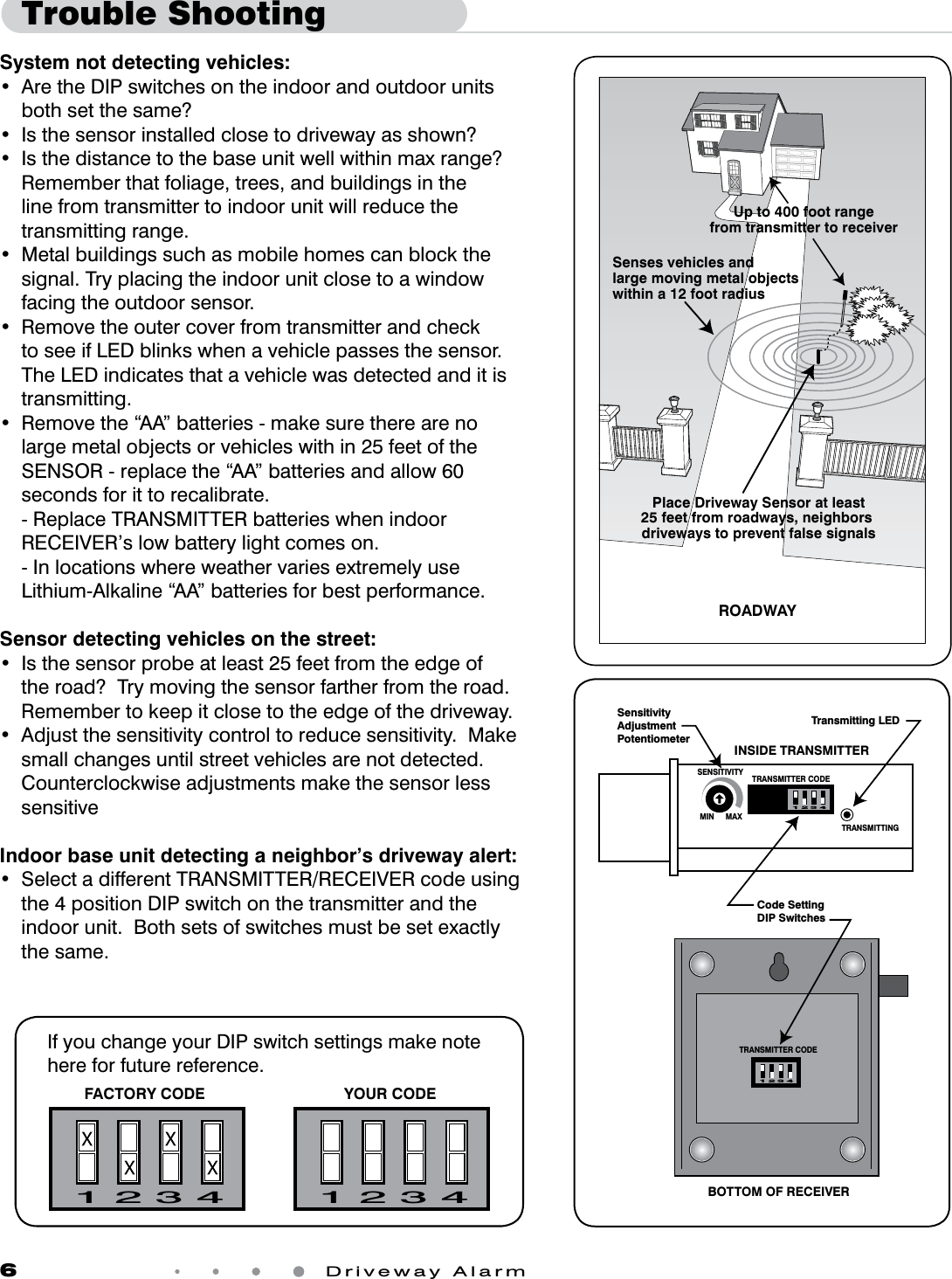
GTO Access Systems, LLC Driveway Alarm

User Manual

Driveway AlarmINSTALLATION MANUALRev. 11/03/09  •  Printed in China for GTO, Inc.How it works:The Transmitter - Sensor:The operating voltage for the transmitter is 3V from two alkaline ‘AA Size’ batteries (not included) inside the transmitter. In cold weather lithium-alkaline batteries will perform best. There is no power switch for this unit. Once the batteries are installed, the unit starts to function. IMPORTANT: Batteries should be installed at the mounting location to ensure proper calibration of the sensor. You should install the batteries at the location by removing the transmitter cover and then replacing it. The approximate transmitting range from the transmitter to the receiver is 400 ft. (at 433MHz). The range may vary depending on environmental conditions such as RF interference, topography and construction of the building. The Receiver:The receiver is powered by an external power adaptor (AC120V 60Hz / DC 12V 100 mA). A rotary switch controls the alert buzzer’s volume on the receiver. There are three LEDs on the front panel of the cabinet, representing power (red), visitor alert (green) and low battery (red). A “RESET” button on the front panel is used to clear the alert LED after it has registered passing vehicles.Thank you for purchasing the Mighty Mule Driveway Alarm. Please read the directions carefully and completely before installing.For more information on Mighty Mule's full line of automatic gate openers and access controls visit our web site at www.mightymule.comACCESS CONTROLSWIRELESSKit Includes:• TransmitterModule• Sensor• Receiver• Transformer• Mountingpost(3pieces)• InstallationmanualSensorMountingpostReceiverTransformerTransmitter
2 Driveway AlarmPlace the SENSOR immediately next to the driveway to maximize the sensing range, but at least 25 feet from roadways, neighbor’s driveways or large moving metal objects. The 15 ft. cable connecting the SENSOR and TRANSMITTER allows for the placement of the TRANSMITTER away from the driveway in the concealment of landscape or closer to the RECEIVER.The approximate transmitting range from the TRANSMITTER to the RECEIVER is 400 ft. Range can vary depending on environmental conditions such as RF interference and topography. Some adjustment may be required. NOTE:  DO NOT place the TRANSMITTER in the direct path of a sprinkler. The module is water resistant but not waterproof.Installation OverviewPlace Driveway Sensor at least25 feet from roadways, neighbors driveways to prevent false signalsSenses vehicles and large moving metal objects within a 12 foot radiusROADWAYUp to 400 foot rangefrom transmitter to receiverFor Optimum Performance:• LocatetheSENSORasfaraspossibleawayfrompowertransformers,powerlines,underground gas line, and telephone lines.• LocatetheSENSORawayfromgeneralmovingtrafctopreventunwantedactivation.RememberthattheSENSORdetectsMAGNETICDISTURBANCEScausedbyavehicle’smass and velocity.• Rangedistanceisapproximateandwillvaryduetooutsideinterference,typeofsoil,vehicle mass, speed, etc.• ItisrecommendedthatyouruntheSignalCableinsidePVCconduittopreventaccidental damage. • DonotruntheSignalCableinconduitwithotherwiressuchasACpowerorothercontrol wires.•TheSIGNALCABLECANNOTBESPLICED.Ifyouneedmorewire,contacttheGTOSalesDepartmentat1-800-543-GATE(4283).
Driveway Alarm                   3IMPORTANT: Clear an area 25 feet in all directions of metal tools, toys and automobiles, to prevent magnetic disturbance during testing and installation.•DeterminetheoptimumlocationfortheSENSORusing the information found in “Installation Overview”. •Digaholeapproximately10-12inchesdeepand24inches long within 2 feet and parallel to the edge of the driveway. •KeeptheSENSORandthecableuncoveredatthistime.DRIVEWAYHOUSE or BUILDINGwhere RECEIVER is locatedROADWAYTRANSMITTER400’ MaxWirelessSENSOR RANGE:12 ft. radius (max)SENSOR:2 feet fromdriveway (max)and 12” deep25 ft. fromneighbor’sdriveway25 ft. fromroadwaySignal CableTransmitter PlacementDetermining Transmitter LocationSensor PlacementDetermining Sensor Location• ChoosealocationfortheTRANSMITTERmodulethatisfarenough from the driveway edge that vehicles are unlikely to hit it. • FifteenfeetofwireisincludedtoallowtheTRANSMITTERtobe 12 to 15 feet from the driveway.• RuntheSENSORcablethroughthePVCmountingpostandplug it into the connector at the bottom of the Transmitter module. • TestthechosenlocationbeforepermanentlytrenchingandsettingtheTRANSMITTER(see“PlacingReceiverandTesting System” section).Connect Sensor Cableto Transmitter Module
4 Driveway AlarmPlacing Receiver and Testing SystemReceiver PlacementRESET BUTTONLOW BATTERY LEDTRANSFORMER INPUTVOLUMN CONTROLVISITOR LEDPOWER LED• PlacetheindoorRECEIVERinaconvenientlocationthatisapproximately 3 ft. above the floor level.• PlugtheACtransformerintoa110VACoutletandthecharger cable into the receiver.•ThepowerLEDonthefrontpanelwilllightup,andtherewillbeaconrmation“beep”tone.• WhenacarpassestheSENSOR,asignalistransmittedtotheRECEIVERfromtheTRANSMITTERbymeansofa433MHzcarrierfrequency.AftertheRECEIVERreceivesthesignal, the buzzer will “beep” twice, and the visit alert LED (green) will flash 3 times and remain lit, until the RESET button is pressed.• TheLOWBATTERYLEDalertsyouwhenthetwo(2)“AA”batteriesintheTRANSMITTERneedtobereplaced.•TesttherangeandsystembyhavingsomeonedriveanautomobilepasttheSENSORtobesuretheRECEIVERisactivatedwhenthevehiclehaspassedtheSENSOR.ItmaynecessarytoadjustthepositionoftheTRANSMITTERforoptimumresults.Testing the System• WithTRANSMITTERindesiredlocationinstalltwo(2)“AA”batteries.•TemporarilyplaceTRANSMITTERonthemountingpostinground.Installing Transmitter BatteriesIMPORTANT: “AA” batteries must be installed at the site where the TRANSMITTER will be located to ensure proper calibration of the transmitter. Insert“AA” Batteries
Driveway Alarm                   5Permanently Install Sensor and TransmitterSensitivity Adjustment•Oncethesystemistestedandworking,permanentlyinstalltheSENSOR,SIGNALCABLEandTRANSMITTER.• BurytheSENSORapproximately10”-12”deep,flat and parallel, next to the driveway.•DiganarrowtrenchorslitfromtheSENSORtotheTRANSMITTERlocationusingaatspadeorothertool.ThewirefromtheSENSORtotheTRANSMITTERshould be at least six inches deep to avoid possible damage from edgers, or lawn aerators.• SecuretheTransmitterModuleonthesupplied3piecePVCpipebyburyingthebottomthirdofthepipeinthesoilandtampingthegroundaroundthepipe.DONOTcover the electronics module with a metal cover as this will cause signal interference.• SecuretheTRANSMITTERmountingpostinthegroundsothattheTRANSMITTERisuprightandapproximately 12” above ground.Transmitter approximately12 inches above groundEdge of DrivewayBury Sensor 10-12 inches deepflat and parallel to driveway• TheRANGEdistancecanbeadjustedfroma3to12footradiusfromtheSENSOR.•ThepotentiometervariesthesensitivityrangeoftheSENSORtoavoidunwantedmovingmetalobjectsfromactivatingtheALARM,suchas:movinggates,metalplayequipment,garagedoors,othervehiculartrafc,etc.• WiththeRANGEadjustedtothemaximumof12feet,alargemetalobjectmovingslowlywillbedetectedupto12feetfromtheSENSOR,whileasmallmetalobjectmovingslowly might not be detected at the same distance. As you moveclosertowardtheSENSOR,thesmallmovingmetalobjectwillatsomepointcauseaDISTURBANCEintheMAGNETICFIELDandactivatetheALARM.MIN MAXSENSITIVITY TRANSMITTER CODETRANSMITTING1 2 3 4INSIDE TRANSMITTERSensitivityAdjustmentPotentiometer
6 Driveway AlarmTrouble ShootingSystem not detecting vehicles:• AretheDIPswitchesontheindoorandoutdoorunitsboth set the same?• Isthesensorinstalledclosetodrivewayasshown?• Isthedistancetothebaseunitwellwithinmaxrange?Remember that foliage, trees, and buildings in the line from transmitter to indoor unit will reduce the transmitting range.• Metalbuildingssuchasmobilehomescanblockthesignal. Try placing the indoor unit close to a window facing the outdoor sensor.• Removetheoutercoverfromtransmitterandcheckto see if LED blinks when a vehicle passes the sensor.  The LED indicates that a vehicle was detected and it is transmitting.• Removethe“AA”batteries-makesuretherearenolargemetalobjectsorvehicleswithin25feetoftheSENSOR-replacethe“AA”batteriesandallow60seconds for it to recalibrate. -ReplaceTRANSMITTERbatterieswhenindoorRECEIVER’s low battery light comes on.  - In locations where weather varies extremely use Lithium-Alkaline “AA” batteries for best performance.Sensor detecting vehicles on the street:• Isthesensorprobeatleast25feetfromtheedgeofthe road?  Try moving the sensor farther from the road.  Remember to keep it close to the edge of the driveway.• Adjustthesensitivitycontroltoreducesensitivity.Makesmall changes until street vehicles are not detected. CounterclockwiseadjustmentsmakethesensorlesssensitiveIndoor base unit detecting a neighbor’s driveway alert:• SelectadifferentTRANSMITTER/RECEIVERcodeusingthe4positionDIPswitchonthetransmitterandtheindoorunit.Bothsetsofswitchesmustbesetexactlythe same.1 2 3 41 2 3 4FACTORY CODE YOUR CODEIf you change your DIP switch settings make note here for future reference.MIN MAXSENSITIVITY TRANSMITTER CODETRANSMITTING1 2 3 4TRANSMITTER CODE1 2 3 4Code Setting DIP SwitchesINSIDE TRANSMITTERBOTTOM OF RECEIVERSensitivityAdjustmentPotentiometerTransmitting LEDPlace Driveway Sensor at least25 feet from roadways, neighbors driveways to prevent false signalsSenses vehicles and large moving metal objects within a 12 foot radiusROADWAYUp to 400 foot rangefrom transmitter to receiver
FCC WARNING: Changes or modications to this unit not expressly approved by the party responsible for compliance could void the user’s authority to operate the equipment. In accordance with FCC Part 15, Section 15.21, the manufac-turer is not responsible for any radio or TV interference caused by unauthorized modications to this equipment. Such modications could VOID the user authority to operate the equipment.NOTE: This equipment has been tested and found to comply with the limits for a Class B digital device, pursuant to Part 15 of the FCC Rules. These limits are designed to provide reasonable protection against harmful interference in a resi-dential installation. This equipment generates, uses and can radiate radio frequency energy and, if not installed and used in accordance with the instructions, may cause harmful interference to radio communications. However, there is no guarantee that interference will not occur in particular installations. If this equipment does cause harmful interference to radio or television reception, which can be determined by turning the equipment off and on, the user is encouraged to try to correct the interference by one or more of the following measures:  • Reorient or replace the receiver antenna. • Increase the separation between the equipment and the receiver. • Connect the equipment into an outlet on a circuit different from that which the receiver is connected. • Consult the dealer or an experienced radio/TV technician for help.GTO Limited One Year Warranty GTO,Inc.,gateopenersandaccessoriesarecoveredunderwarrantybythemanufactureragainstdefectsinmaterialsandmanufacturer workmanship for a period of one (1) year from date of purchase, provided the recommended installation procedures have been followed.In the case of product failure due to defective material or manufacturer workmanship within the one (1) year warranty period, the productwillberepairedorreplaced(atthemanufacturer’soption)atnochargetothecustomer,ifreturnedfreightprepaidtoGTO,Inc.,3121HartseldRoad,Tallahassee,Florida,USA32303.IMPORTANT: Call (800) 543-1236 for a Return Goods Authorization (RGA) number before returning accessory to factory.  ProductsreceivedatthefactorywithoutanRGAnumberwillnotbeaccepted.  Replacement or repaired parts are covered by this warranty for the remainder of the one (1) year warranty period or six (6) months,whicheverisgreater.GTO,Inc.willpaytheshippingcharges(equaltoUnitedParcelServiceGROUNDrate)forreturntotheowner of items repaired under warranty. The manufacturer will not be responsible for any charges or damages incurred in the removal of the defective parts for repair, or for the reinstallation of those parts after repair. This warranty shall be considered void if damage to the product(s) was due to improper installationoruse,connectiontoanimproperpowersource,orifdamagewascausedbylightning,wind,re,ood,insectsorothernatural agent.Aftertheone(1)yearwarrantyperiod,GTO,Inc.willmakeanynecessaryrepairsforanominalfee.CallGTOat(800)543-1236formoreinformation.Thiswarrantygivesyouspeciclegalrights,andyoumayalsohaveotherrightswhichmayvaryfromstateto state. This warranty is in lieu of all other warranties, expressed or implied. NOTE: Verification of the warranty period requires copies of receipts or other proof of purchase. Please retain these records.GTO,Inc.•3121HartseldRoad•Tallahassee,Florida323031-800-543-GATE(4283)•TechnicalSupport1-800-543-1236www.mightymule.comFor online Technical Support visit the Online Troubleshooter Wizard 24 hrs/day 7 days/week athttp://support.gtoinc.com/support/troubleshooter.aspxand open a Tech TicketTechnicalSupportHours:MON-FRI8:00AM-7:00PM(ET)(800) 543-1236

Navigation menu