Nortek Security and Control 00117 Receiver for Security / Remote Control Transceiver User Manual 235667A SW ATT GDC Instructions indd
Nortek Security & Control LLC Receiver for Security / Remote Control Transceiver 235667A SW ATT GDC Instructions indd
Contents
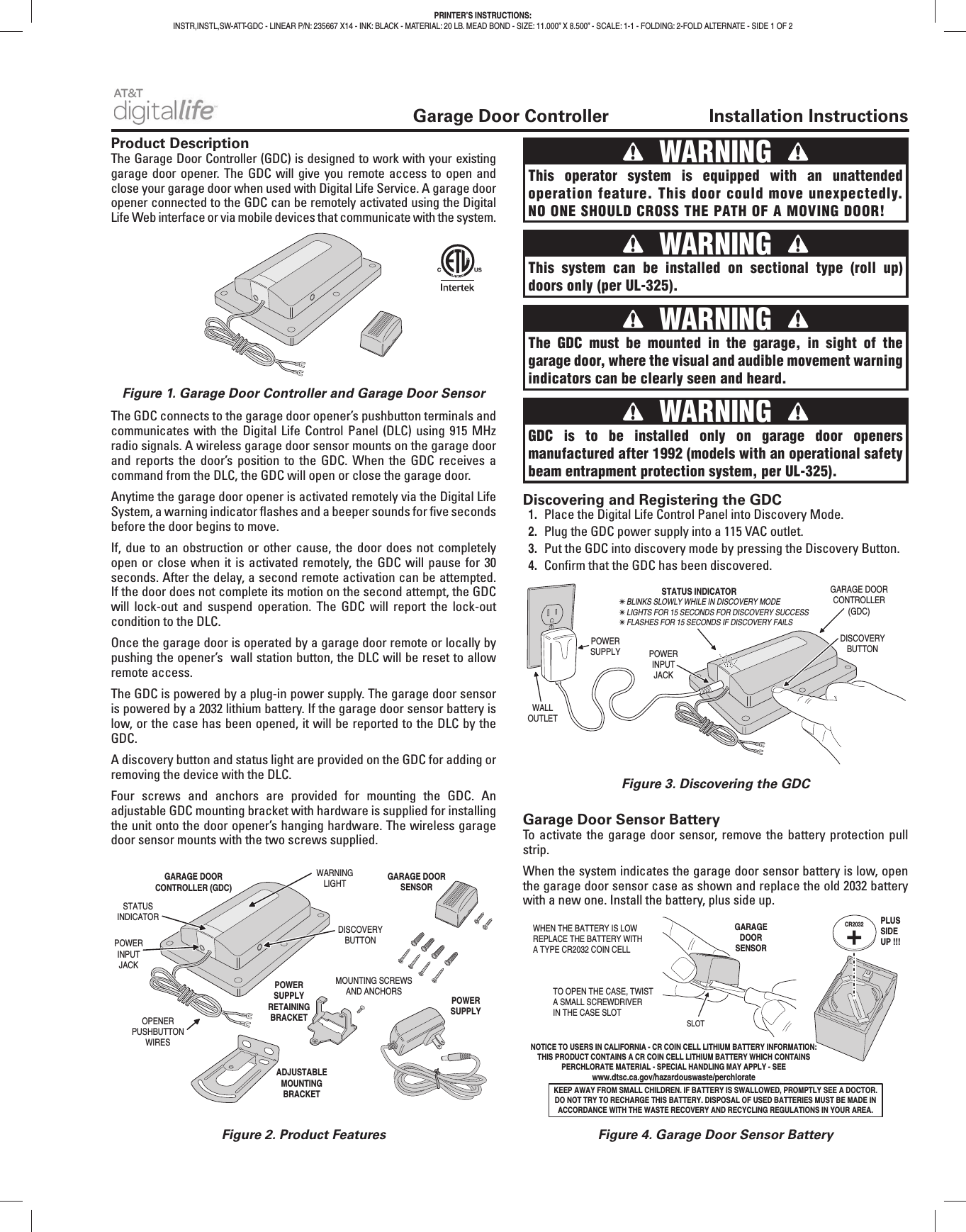
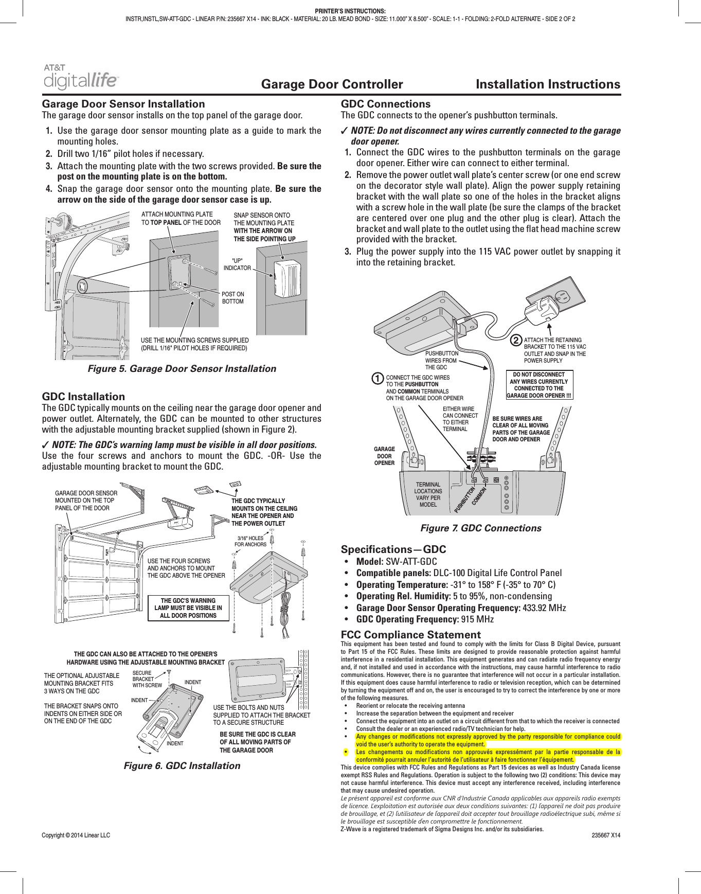
- 1. User manual
- 2. User Manual
User manual