Nortek Security and Control 00139 PlugZ Dimmer User Manual 10008250X7 PD300EMZ5 1A Instructions indd
Nortek Security & Control LLC PlugZ Dimmer 10008250X7 PD300EMZ5 1A Instructions indd
Users Manual
1
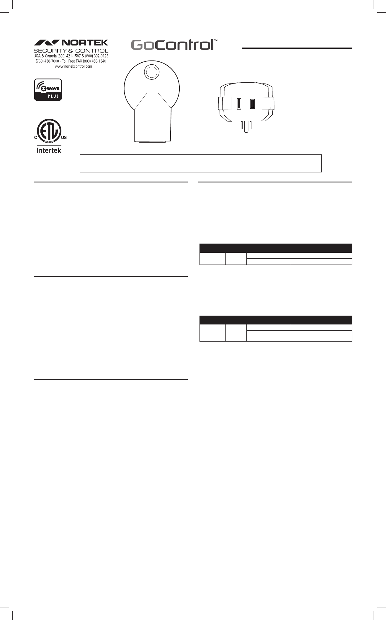
PD300EMZ5-1 PLUG-IN MODULE
The GoControl™ family of Z-Wave® certifi ed wireless lighting products (smart LED fi xtures,
bulbs, switches, dimmers, outlets, plug-in modules) Control Products (thermostats, irrigation
controller and garage door controller)and Sensors (fl ood, leak, alert sounder, motion sensor
and door/window sensor) bring a new level of intelligent wireless Home Automation capability to
commercial and residential environments.
The Z-Wave wireless protocol is an international wireless standard for remote home automation,
security and other applications. This product can be included and operated in any Z-Wave
network with other Z-Wave certifi ed devices from other manufacturers and/or other applications.
All non-battery operated nodes within the network will act as repeaters regardless of vendor to
increase reliability of the network.
GoControl Z-Wave products are easy to install, are Z-Wave certifi ed, and allow dealers to create
an integrated wireless network with nearly limitless expansion and interoperability with security,
energy management, home entertainment, appliances, and more.
Z-WAVE PLUS FEATURES
The PD300EMZ5-1 contains a Z-Wave 500 Series Module that supports Z-Wave Plus®
features. A Z-Wave certifi ed portable or stationary Controller can communicate with the Z-Wave
500 Series Module.
Depending on the capability of the Controller or gateway software, the following operations can
be performed with the PD300EMZ5-1. Refer to the Controller or gateway manual for details.
• Turn the load ON and OFF.
• Add or Remove the PD300EMZ5-1.
• Assign the PD300EMZ5-1 to a specific Group/Scene and/or to include the load as part of
ALL ON or ALL OFF system commands.
• Over-the-air firmware update by the gateway or static Controller.
• Lifeline function which automatically notifies the associated modules and the network that
a manually reset device is no longer in the network, thus, the corresponding association
becomes invalid.
• Monitors the amount of energy being used and reports the current usage to the Z-Wave
controller
INSTALLATION
Adding to a network:
Refer to your Controller operating instructions to add this switch under the command of the
Wireless Controller.
1. With your Controller in Discovery or Add Mode, tap the button on the face of the outlet. The
LED will blink slowly when in ADD Mode.
2. You should see an indication on your Controller that the “device was added” to the network
and the LED will stop blinking.
3. The device will appear in the list of Switches. It should display as a switch.
If the Controller/Gateway shows the addition failed, repeat Steps 1-3.
✓NOTE: If you have trouble adding the PD300EMZ5-1 to a group it may be that the Home ID
and Node ID were not cleared from it after testing. You must fi rst “RESET UNIT” to remove
it from the network. Although adding it to a group includes it in the network, removing it from
a group does not remove it from the network. If removed from a group, it functions as a
repeater (only). “RESET UNIT” removes it completely from the network.
To Reset Unit (If Required):
In the event that your primary Controller is lost or otherwise inoperable, to reset the PD300EMZ5-1 and clear
all network information, follow these steps:
1. Tap the button on the face of the outlet five (5) times.
2. Press and hold the button for 15 seconds. The LED will increasingly blink faster to indicate that a Reset
is taking place.
3. LED will turn off when reset is complete.
Removing from a network:
The PD300EMZ5-1 can be removed from the network by the Controller/Gateway. Refer to the
Controller operating instructions for details.
1. Set the Controller into Removal Mode and follow its instruction to delete the PD300EMZ5-1
from the Controller.
2. Remove the switch by tapping the button on the face of the outlet 2 times. The LED will begin
blinking slowly for 10 seconds indicating that it has been removed.
3. You should see an indication on your Controller that the “device was removed” from the
network.
BASIC OPERATION
Local Control
The button on the PD300EMZ5-1 allows the user to:
• Pressing and holding the button will dim or brighten the load attached.
• Turn the attached load on or off.
• Tapping the button on the face of the outlet turns the load attached ON to OFF.
Load Sense
Load Sense, when enabled, will turn the PD300EMZ5-1 on without having to use the Controller’s
application or pressing the button. When the attached load is turned OFF then ON, the
PD300EMZ5-1 will turn ON.
Parameter Length Valid Values Confi guration Option
29 1 Byte 0Load Sense Disabled
1 Load Sense Enabled (default)
Night Light
To act as a night light, the LED on the PD300EMZ5-1 will turn ON when the load attached is
OFF. However, the LED can be user confi gured to turn ON, when the load attached is ON, if so
desired. See “CONFIGURATION” section.
Energy Monitoring
PD300EMZ5-1eports the total accumulated Kilowatt Hours (kWh) and the instantaneous Watts
being consumed by the load.
Parameter Length Valid Values Confi guration Option
13 1 Byte
0Automatic reporting OFF
1-255 Number of minutes between
automatic reporting (Default = 6)
Confi guration Parameter 13 confi gures the rate at which the energy readings are reported. If
the maximum kWh value that can be reported is reached (21,474 kWh), then it will remain at the
maximum level until reset to 0.
To reset, the total accumulated kWh used by the PD300EMZ5-1 the Z-Wave controller needs
to send a reset command at the request of the user. It will also be reset if the PD300EMZ5-1 is
excluded from the Z-Wave network using the Controller software.
The Watts reading provides the immediate reading of the power being consumed by the load.
The Watts reading takes several seconds to settle so wait a few seconds before reading the
energy value when the state of the switch (on / off) has changed.
Remote Control
The PD300EMZ5-1 will respond to BASIC and BINARY commands that are part of the Z-Wave
system. Refer to your Controller’s instructions as to whether your Controller can transmit those
commands.
Protection Mode
The PD300EMZ5-1 supports Protection Mode that is used to disable the button on the front
of the device. This eliminates inadvertent activation of the switch. To enable Protection Mode,
press the button on the PD300EMZ5-1 three times quickly. The LED will blink Purple twice
showing that Protection Mode has been enabled. When Enabled the only way to turn ON or
OFF the PD300EMZ5-1 is through the Z-Wave controller or Mobile app. If the button on the
PD300EMZ5-1 is pressed, the LED will blink Purple twice and have no impact on the attached
device. To exit Protection Mode, press the button three times.
Associations
The PD300EMZ5-1 supports one Group with fi ve Nodes for lifeline communication. Group
1 must be assigned the Node ID of the Controller to which unsolicited notifi cations from the
PD300EMZ5-1 will be sent. The Z-Wave Controller should set this Association automatically
after inclusion. You can associate up to fi ve Z-Wave devices to Group 1.
For instructions on how to “set Lifeline Association” please refer to your wireless Controller
instructions.
Removing Associations
To remove the Associations, if the Controller has recognized the Associations, refer to the
Z-Wave Controller’s instructions on how to remove Associations. If the Controller has not
recognized the Associations, removing the PD300EMZ5-1 from the Z-Wave network will
eliminate the Associations.
PRINTER’S INSTRUCTIONS:
INSTR,INSTL,PD300EMZ5-1,GO CONTROL P/N 10008250 X8 ; INK: BLACK; MATERIAL; 20# MEAD BOND; SIZE: 8.500” x 14.000”; TOLERANCE ± .125”; SCALE: 1-1; FOLDING: FOLD PAGE 4 X FINISH WITH LOGO
SHOWING; PAGE 1 OF 2
PD300EMZ5-1
Z-Wave Radio Frequency (RF) Controlled, 120 VAC
300 Watt, Plug-In Dimmer Series 500
NOTE: This unit must be added to the Network only where it will be permanently installed. The proper operation of this node in the mesh
network is dependent on it knowing its location with respect to other nodes. You cannot “test bench” confi gure this unit, then install.
Bottom of Appliance Module
showing 2 prong plug-in
2
ADVANCED OPERATION
All On/All Off
The PD300EMZ5-1 supports the ALL ON / ALL OFF commands. The PD300EMZ5-1 can be set
to respond to ALL ON and ALL OFF commands four different ways.
Refer to your Controller for information on how to set the PD300EMZ5-1 to operate in the
manner you desire. Some Controllers may be only able to set certain settings of ALL ON/ALL
OFF response.
The four different ways the PD300EMZ5-1 can be setup to respond to ALL ON and ALL OFF
commands are:
1. Responds to ALL ON or the ALL OFF command.
2. Responds to ALL OFF command but will not respond to ALL ON command.
3. Responds to ALL ON command but will not respond to ALL OFF command.
4. Responds to ALL ON and the ALL OFF command.
CONFIGURATION
Adjusting Dim Rate
Dim Level
The brightness setting of the Dimmer is called the Dim Level. When the Dim Level is adjusted,
the rate that Dim Level changes depends on the Dim Step (Parameter 7) and Dim Timer
(Parameter 8) values. These values can be changed instantly to allow various scenes and
effects. These values can also vary between local control, remote commands from the hub or
associated device and ALL ON/OFF commands.
Dim Step (remote and local)
Dim Step can be set to a value of 1 to 99. This value indicates how many levels the dimmer
will change each time the Dim Timer expires.
Dim Timer (remote and local)
The Dim Timer (how fast the dim steps happen). It can be set to a value of 1 to 255. This value
indicates in 10 millisecond resolution, how often the dim level will change.
Examples:
• If the Dim Timer parameter value is set to 1, every 10mS the Dim Level will change by the
Dim Step value.
• If the Dim Timer parameter value is set to 255, every 2.55 seconds the Dim Level will change
by the Dim Step value.
With the combination of the two parameter values that control the dim rate, the dimmer can
be adjusted to dim from maximum to minimum or minimum to maximum at various speeds
between 10 millisecond and 252.45 seconds (over 4.25 minutes).
Parameter Length Valid
Values
Confi guration Option
7 1 byte 1 – 99 Dim Remote On/Off Step (default = 3, 3 steps)
8 1 byte 1 – 255 Dim Remote On/Off Timer (default = 10, 10 mS)
9 1 byte 1 – 255 Dim Local On/Off Step (default = 10, 10 steps)
10 1 byte 1 - 255 Dim Local On/Off Timer (default = 10, 10 mS)
11 1 byte 1 - 99 Dim ALL On/Off Step (default = 10, 10 steps)
12 1 byte 1 - 255 Dim ALL On/Off Timer (default = 3, 3 mS)
LED Intensity
You can set the intensity of the LED to fi t the environment the PD300EMZ5-1 is being used in
from off to full brightness. This is done by changing Parameter 2.
Parameter Length Valid Values Confi guration Option
21 byte 0 - 99 0 = OFF
1 = Very Dim
99 = Full Brightness (default)
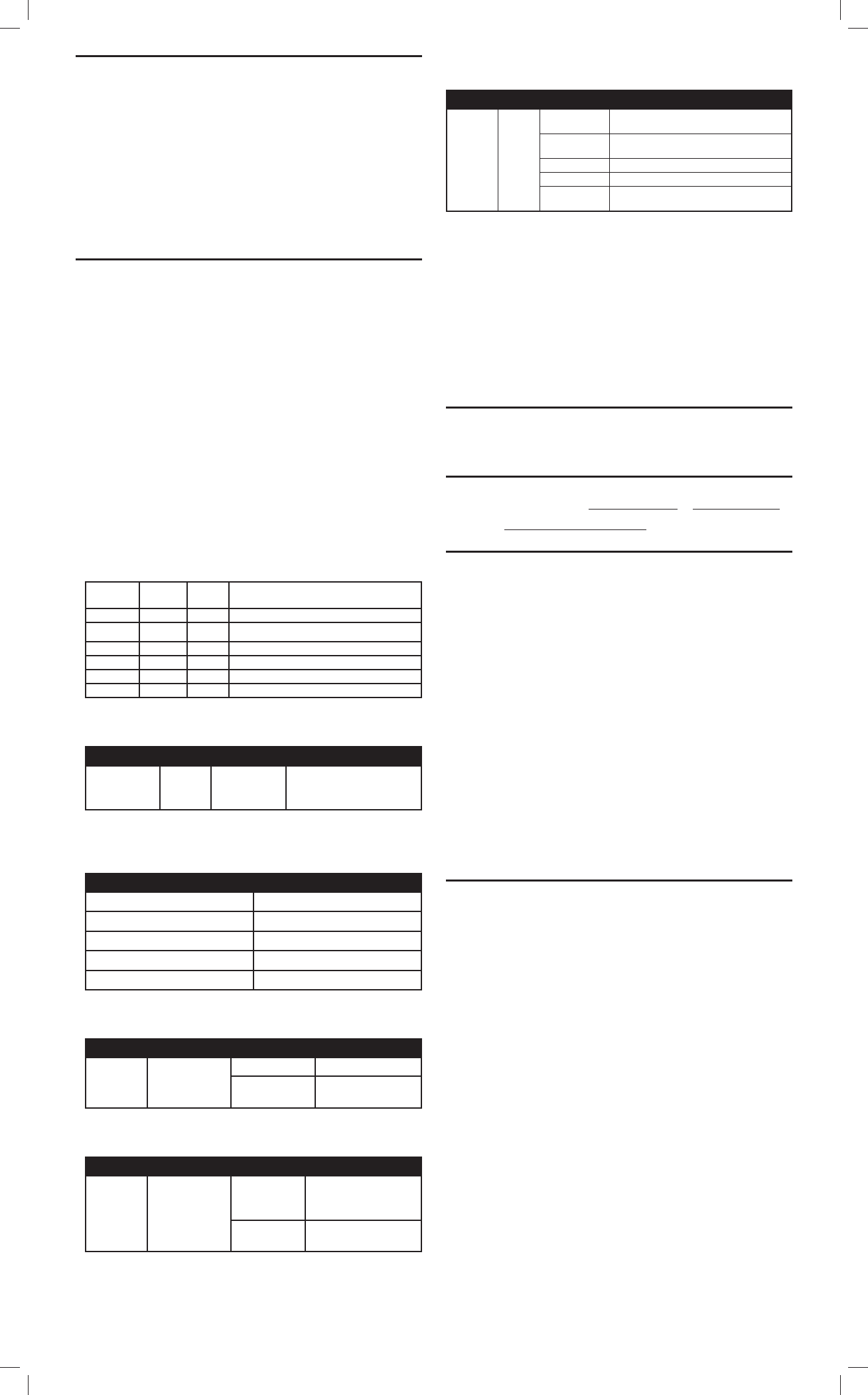
Power Monitoring
The PD300EMZ5-1 provides a visual display of the amount of energy being
consumed when the switch is turned on by illuminating the LEDs in one of 5
different colors.
Energy
0 to 2 Watts White
3 to 60 Watts Green
60 to 100 Watts Blue
101 to 200 Watts Yellow
201 to 300 Watts Red
The Power Monitoring can be turned off untilizing Parameter 11. When turned off, the
PD300EMZ5-1 will no longer illuminate the LED to indicate any energy use and periodic
reports to the hub on energy use will also be turned off.
Parameter Length Valid Values Confi guration Option
11 1 Byte 0 Power Monitoring OFF
1 Power Monitoring ON
(Default)
The duration the LED will change color to indicate the amount of energy being
used can be set using Parameter 12. After displaying the “energy used” color, the
LED wil revert to OFF or ON (white) as determinded by confi guration parameter #3.
Parameter Length Valid Values Confi guration Option
12 1 Byte 1 - 254 Number of seconds LED
displays power level usage.
Default = 60
255 Power Level usage
continuous ON
The PD300EMZ5-1 supports the Confi guration command. Each unit can be confi gured to
operate slightly differently than how it works when you fi rst install it.
Using the Confi guration command you can confi gure the following:
Night Light
By default, the LED on the PD300EMZ5-1 will turn OFF when the load attached is turned ON.
To make the LED turn ON when the load attached is turned ON, set Parameter 3 to a value of 1.
Parameter Length Valid Values Confi guration Option
31 Byte
0LED OFF when the load is on, and ON when
the load is off (default mode)
1LED ON when the load is on, and OFF when
the load is off
2 LED is always on
3 LED is always off
4LED blinks during RF transmissions from or
to the device
Over-The-Air (OTA) Update
A Quadruple tap of the switch enables the fi rmware update mode. Firmware update mode
must be entered before the system Controller sends the fi rmware update command to begin
downloading new fi rmware. Firmware update mode is enabled for 60 seconds after the
quadruple tap. If the Firmware update does not begin before the end of the 60 seconds then
fi rmware update mode is exited returns to normal operation. The LED “winks” twice per second
indicating it is in fi rmware update mode.
Resetting to Defaults
Each confi guration Parameter can be set back to its default setting by setting the default bit
in the Confi guration Set command. See your Controller’s instructions on how to do this
(and if it supports it). All confi guration commands will be reset to their default state when the
PD300EMZ5-1 is excluded from the Z-Wave network by using the Controller to reset the node.
SPECIFICATIONS
Power: 120 VAC, 60 Hz
Signal (Frequency): 908.42 MHz / 916 MHz
Maximum Load: 300 W for lamps only 120 VAC
Range: Up to 130 feet line of sight
NOTICES
Z-Wave® and Z-Wave Plus® are registered trademarks of Sigma Designs and its subsidiaries in the United
States and other countries.
Covered by one or more claims of patents: http://sipcollc.com/patent-list/ and http://intusiq.com/patent-list/
Terms and Conditions pertaining to the sale of this Nortek Security & Control wireless mesh network product
are available at http://nortekcontrol.com/terms_conditions.php
REGULATORY INFORMATION
We, Nortek Security & Control, LLC, of 1950 Camino Vida Roble STE 150, Carlsbad, CA 92008, declare
under our sole responsibility that the device PD300EMZ5-1 complies with Part 15 of the Fcc rules.
This device complies with part 15 of the FCC Rules. Operation is subject to the following two conditions: (1)
This device may not cause harmful interference, and (2) This device must accept any interference received,
including interference that may cause undesired operation.
FCC Notice
This equipment has been tested and found to comply with the limits for a Class B digital device, pursuant
to Part 15 of the FCC Rules. These limits are designed to provide reasonable protection against harmful
interference in a residential installation.
This equipment generates, uses, and can radiate radio frequency energy and, if not installed and used in
accordance with the instructions may cause harmful interference to radio communications. However, there is
no guarantee that interference will not occur in a particular installation. If this equipment does cause harmful
interference to radio or television reception, which can be determined by turning the equipment off and on, the
user is encouraged to try to correct the interference by one or more of the following measures:
• Reorient or relocate the receiving antenna.
• Increase the separation between the equipment and receiver
• Connect the equipment into an outlet on a circuit different from that to which the receiver is connected
• Consult the dealer or an experienced radio/TV technician to help.
Changes or modifi cations not expressly approved by the party responsible for compliance could void
the user’s authority to operate the equipment
IC Notice
This Class B digital apparatus complies with Canadian ICES-003
Cet appareil numérique de la classe B est conforme à la norme NMB-003 du Canada. Le présent appareil
est conforme aux CNR d’Industrie Canada applicables aux appareils radio exempts de licence. L’exploitation
est autorisée aux deux conditions suivantes : (1) l’appareil ne doit pas produire de brouillage, et (2) l’utilisateur
de l’appareil doit accepter tout brouillage radioélectrique subi, même si le brouillage est susceptible d’en
compromettre le fonctionnement.
This device complies with the Industry Canada license exempt RSS standard(s). Operation is subject to
the following two conditions: (1) this device may not cause interference, and (2) this device must accept any
interference, including interference that may cause undesired operation of the device.
WARRANTY
What is Covered?
Nortek Security & Control (“NS&C”) warrants to consumers who purchase this product for personal,
family or household purposes new from NS&C directly or from an authorized NS&C dealer, that the
product will be free from defects in materials and workmanship for a period of (1) year from the date
of purchase. This warranty only applies if the product is installed at a residence in the 50 United
States or District of Columbia, and only at the site of the original installation. It is not transferable. This
warranty is not extended to resellers.
If a defect exists, NS&C will have you ship the defective part or product to us and we will, at our option, either
repair or replace it. This warranty does not cover the cost of labor to remove a defective part or product or to
reinstall any repaired or replacement part or product
This warranty does not cover defects or damages caused by improper handling, maintenance, storage,
installation, removal or re-installation, misuse, non-factory authorized modifi cation or alteration, use of
incompatible accessories, electrical power problems or surges, impact by foreign objects, accident, fi re, acts
of God, normal wear and tear or shipping damage other than a shipment from NS&C. Note that all NS&C
products are designed to be installed, removed and serviced by trained individuals or professionals.
Keep your original sales receipt as it will be required to obtain warranty service.
This warranty shall not be extended or restarted upon receipt of any repaired or replacement part or product
under this warranty. No person is authorized to extend or otherwise modify this warranty.
How do I Obtain Warranty Service?
To obtain warranty service, email our Returns Department at returns@nortek.com. Include your name,
address, telephone number, the model number of your product, a copy of your original sales receipt, and
a description of the problem. Unless we need to discuss the situation further with you, you will be emailed a
Return Authorization Number and shipping instructions. If we need to discuss the situation further with you,
we will call or email you. NS&C may require troubleshooting on installed product before a Return Authorization
Number is issued. Anything shipped to us without a Return Authorization Number will be automatically returned
unopened. You are responsible for the charges for shipment to us, unless you are a California resident.
Limitations
THE DURATION OF ANY IMPLIED WARRANTY, INCLUDING THE WARRANTIES OF MERCHANTABILITY AND
FITNESS FOR A PARTICULAR PURPOSE, SHALL NOT EXCEED THE WARRANTY PERIOD PROVIDED HEREIN.
Some states do not allow limitations on how long an implied warranty lasts, so the above limitation may not apply
to you.
NS&C SHALL NOT BE LIABLE FOR ANY INCIDENTAL OR CONSEQUENTIAL DAMAGES RESULTING FROM THE
BREACH OF ANY WRITTEN OR IMPLIED WARRANTY.
Some states do not allow the exclusion or limitation of incidental or consequential damages, so the above limitation
or exclusion may not apply to you.
This warranty gives you specifi c legal rights, and you may also have other legal rights which vary from State
to State.
PRINTER’S INSTRUCTIONS:
INSTR,INSTL,PD300EMZ5-1,GO CONTROL; P/N 10008250 X8 INK: BLACK; MATERIAL: 20# MEAD BOND; SIZE: 8.500” x 14.000”; TOLERANCE ± .125”; SCALE: 1-1 FOLDING: FOLD PAGE 4 X FINISH WITH LOGO SHOWING;
PAGE 2 OF 2
Copyright © 2015 Nortek Security & Control LLC 10008250 X8