Nortek Security and Control 00142 Phase Controlled Light Dimmer User Manual 10008092X13 WD500Z5 1 WD1000Z5 1 Instructions indd

Nortek Security & Control LLC Phase Controlled Light Dimmer 10008092X13 WD500Z5 1 WD1000Z5 1 Instructions indd
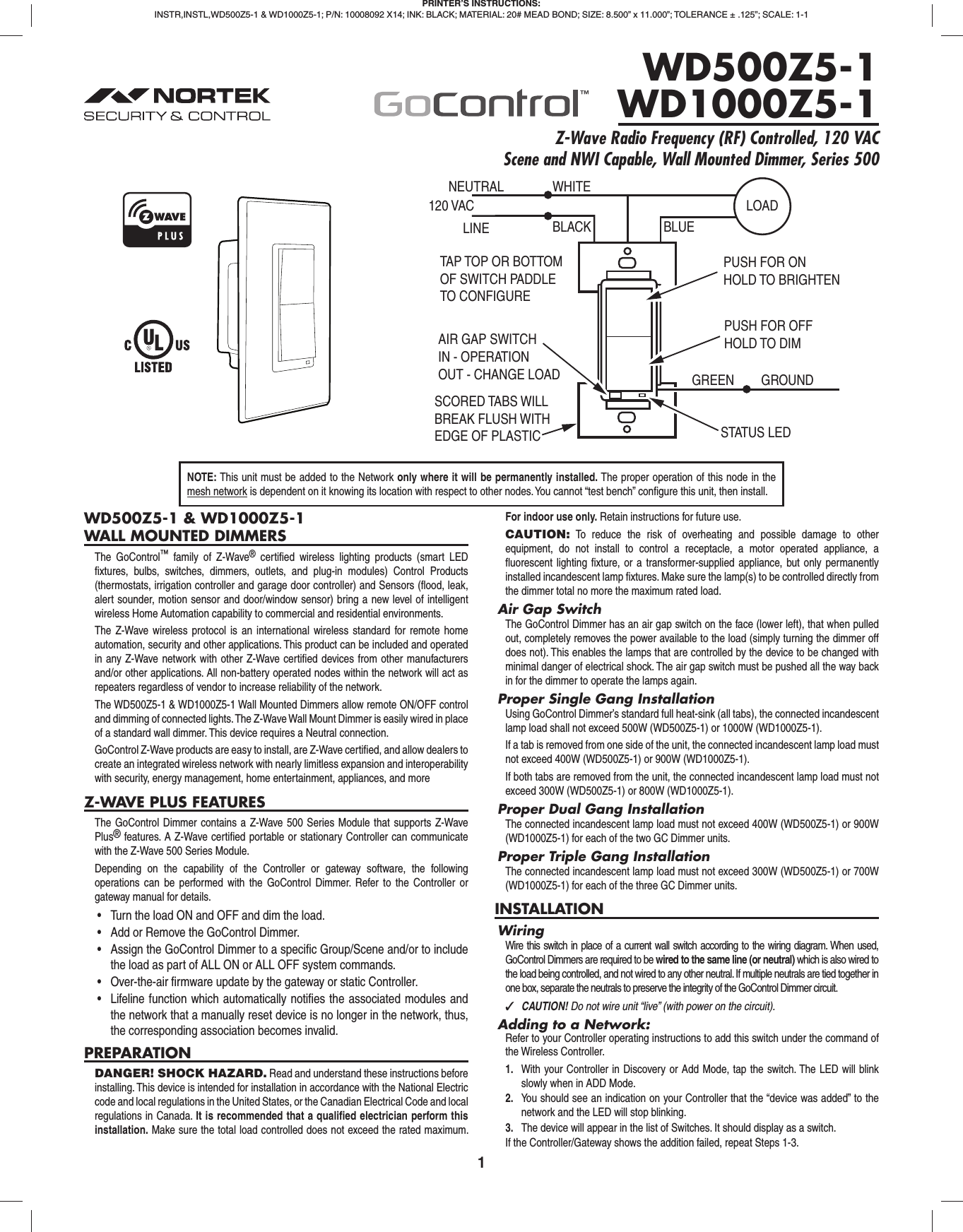
Users Manual

1WD500Z5-1 & WD1000Z5-1WALL MOUNTED DIMMERSThe GoControl™ family of Z-Wave® certifi ed wireless lighting products (smart LED fi xtures, bulbs, switches, dimmers, outlets, and plug-in modules) Control Products (thermostats, irrigation controller and garage door controller) and Sensors (fl ood, leak, alert sounder, motion sensor and door/window sensor) bring a new level of intelligent wireless Home Automation capability to commercial and residential environments.The Z-Wave wireless protocol is an international wireless standard for remote home automation, security and other applications. This product can be included and operated in any Z-Wave network with other Z-Wave certifi ed devices from other manufacturers and/or other applications. All non-battery operated nodes within the network will act as repeaters regardless of vendor to increase reliability of the network.The WD500Z5-1 & WD1000Z5-1 Wall Mounted Dimmers allow remote ON/OFF control and dimming of connected lights. The Z-Wave Wall Mount Dimmer is easily wired in place of a standard wall dimmer. This device requires a Neutral connection.GoControl Z-Wave products are easy to install, are Z-Wave certifi ed, and allow dealers to create an integrated wireless network with nearly limitless expansion and interoperability with security, energy management, home entertainment, appliances, and moreZ-WAVE PLUS FEATURESThe GoControl Dimmer contains a Z-Wave 500 Series Module that supports Z-Wave Plus® features. A Z-Wave certifi ed portable or stationary Controller can communicate with the Z-Wave 500 Series Module.Depending on the capability of the Controller or gateway software, the following operations can be performed with the GoControl Dimmer. Refer to the Controller or gateway manual for details.•  Turn the load ON and OFF and dim the load.•  Add or Remove the GoControl Dimmer.•  Assign the GoControl Dimmer to a specific Group/Scene and/or to include the load as part of ALL ON or ALL OFF system commands.•  Over-the-air firmware update by the gateway or static Controller.•  Lifeline function which automatically notifies the associated modules and the network that a manually reset device is no longer in the network, thus, the corresponding association becomes invalid.PREPARATIONDANGER! SHOCK HAZARD. Read and understand these instructions before installing. This device is intended for installation in accordance with the National Electric code and local regulations in the United States, or the Canadian Electrical Code and local regulations in Canada. It is recommended that a qualifi ed electrician perform this installation. Make sure the total load controlled does not exceed the rated maximum. For indoor use only. Retain instructions for future use.CAUTION: To reduce the risk of overheating and possible damage to other equipment, do not install to control a receptacle, a motor operated appliance, a fl uorescent lighting fi xture, or a transformer-supplied appliance, but only permanently installed incandescent lamp fi xtures. Make sure the lamp(s) to be controlled directly from the dimmer total no more the maximum rated load.Air Gap SwitchThe GoControl Dimmer has an air gap switch on the face (lower left), that when pulled out, completely removes the power available to the load (simply turning the dimmer off does not). This enables the lamps that are controlled by the device to be changed with minimal danger of electrical shock. The air gap switch must be pushed all the way back in for the dimmer to operate the lamps again.Proper Single Gang InstallationUsing GoControl Dimmer’s standard full heat-sink (all tabs), the connected incandescent lamp load shall not exceed 500W (WD500Z5-1) or 1000W (WD1000Z5-1).If a tab is removed from one side of the unit, the connected incandescent lamp load must not exceed 400W (WD500Z5-1) or 900W (WD1000Z5-1).If both tabs are removed from the unit, the connected incandescent lamp load must not exceed 300W (WD500Z5-1) or 800W (WD1000Z5-1).Proper Dual Gang InstallationThe connected incandescent lamp load must not exceed 400W (WD500Z5-1) or 900W (WD1000Z5-1) for each of the two GC Dimmer units.Proper Triple Gang InstallationThe connected incandescent lamp load must not exceed 300W (WD500Z5-1) or 700W (WD1000Z5-1) for each of the three GC Dimmer units.INSTALLATIONWiringWire this switch in place of a current wall switch according to the wiring diagram. When used, GoControl Dimmers are required to be wired to the same line (or neutral) which is also wired to the load being controlled, and not wired to any other neutral. If multiple neutrals are tied together in one box, separate the neutrals to preserve the integrity of the GoControl Dimmer circuit. ✓CAUTION! Do not wire unit “live” (with power on the circuit).Adding to a Network:Refer to your Controller operating instructions to add this switch under the command of the Wireless Controller.1.  With your Controller in Discovery or Add Mode, tap the switch. The LED will blink slowly when in ADD Mode.2.  You should see an indication on your Controller that the “device was added” to the network and the LED will stop blinking.3.  The device will appear in the list of Switches. It should display as a switch.If the Controller/Gateway shows the addition failed, repeat Steps 1-3.PRINTER’S INSTRUCTIONS:INSTR,INSTL,WD500Z5-1 & WD1000Z5-1; P/N: 10008092 X14; INK: BLACK; MATERIAL: 20# MEAD BOND; SIZE: 8.500” x 11.000”; TOLERANCE ± .125”; SCALE: 1-1WD500Z5-1WD1000Z5-1Z-Wave Radio Frequency (RF) Controlled, 120 VAC Scene and NWI Capable, Wall Mounted Dimmer, Series 500NEUTRAL120 VACPUSH FOR ONHOLD TO BRIGHTENWHITELINE BLACKPUSH FOR OFFHOLD TO DIMSTATUS LEDGREEN GROUNDTAP TOP OR BOTTOMOF SWITCH PADDLETO CONFIGUREAIR GAP SWITCHIN - OPERATIONOUT - CHANGE LOADSCORED TABS WILLBREAK FLUSH WITHEDGE OF PLASTICBLUELOADNOTE: This unit must be added to the Network only where it will be permanently installed. The proper operation of this node in the mesh network is dependent on it knowing its location with respect to other nodes. You cannot “test bench” confi gure this unit, then install.
2 ✓NOTE: If you have trouble adding the GoControl Dimmer to a group it may be that the Home ID and Node ID were not cleared from it after testing. You must fi rst “RESET UNIT” to remove it from the network. Although adding it to a group includes it in the network, removing it from a group does not remove it from the network. If removed from a group, it functions as a repeater (only). “RESET UNIT” removes it completely from the network.To Reset Unit (If Required):In the event that your primary Controller is lost or otherwise inoperable, to reset the GoControl Dimmer and clear all network information, follow these steps:1.  Tap the top of the switch fi ve (5) times.2.  Press and hold the bottom of the switch for 15 seconds. The LED will increasingly blink faster to indicate that a Reset is taking place.Removing from a Network:The GoControl Dimmer can be removed from the network by the Controller/Gateway. Refer to the Controller operating instructions for details.1.  Set the Controller into Removal Mode and follow its instruction to delete the GoControl Dimmer from the Controller.2.  Remove the switch by tapping the paddle 2 times. The LED will begin blinking slowly for 10 seconds indicating that it has been removed.3.  You should see an indication on your Controller that the “device was removed” from the network.BASIC OPERATIONLocal ControlPushing the top or bottom of the switch, the WD500Z-1 allows the user to do the following:•  Turn ON, OFF, DIM or BRIGHTEN the load attached.•  Configure to Control Shades or Window Coverings via Z-Wave network.•  Control other Z-Wave enabled devices. Also, when a controller prompts you to “Send Node ID” or to “Press Button on Unit”, quickly tap the top or bottom of the switch once to satisfy those instructions.•  Tapping top of the switch turns the load attached to the previous ON level.•  Tapping bottom of the switch turns the load attached OFF.•  Pressing and holding the top of the switch will brighten the load attached, and pressing and holding the bottom of the switch will dim the load. When OFF, pressing and holding the bottom of the switch will cause the load to go to the minimum dim level. ✓NOTE: Upon restoration of power after a power loss, the WD500Z-1 returns to previous known state.LED IndicationTo act as a night light, the LED on the GoControl Dimmer will turn ON when the load attached is OFF. However, the LED can be user confi gured to turn ON, when the load attached is ON, if so desired. See “CONFIGURATION” section.Remote ControlThe GoControl Dimmer will respond to BASIC and BINARY commands that are part of the Z-Wave system. Refer to your Controller’s instructions as to whether your Controller can transmit those commands.ADVANCED OPERATIONAll On/All OffThe GoControl Dimmer supports the ALL ON / ALL OFF commands. The GoControl Dimmer can be set to respond to ALL ON and ALL OFF commands four different ways.Refer to your Controller for information on how to set the GoControl Dimmer to operate in the manner you desire. Some Controllers may be only able to set certain settings of ALL ON/ALL OFF response.The four different ways the GoControl Dimmer can be setup to respond to ALL ON and ALL OFF commands are:1.  Responds to ALL ON or the ALL OFF command.2.  Responds to ALL OFF command but will not respond to ALL ON command.3.  Responds to ALL ON command but will not respond to ALL OFF command.4.  Responds to ALL ON and the ALL OFF command.AssociationsThe GoControl Dimmer supports one Group with fi ve Nodes for lifeline communication. Group 1 must be assigned the Node ID of the Controller to which unsolicited notifi cations from the GoControl Dimmer will be sent. The Z-Wave Controller should set this Association automatically after inclusion. You can associate up to fi ve Z-Wave devices to Group 1. Lifeline Association only supports the “manual reset” event.For instructions on how to “set Lifeline Association” please refer to your wireless Controller instructions.Creating Associations1.  Learn all devices into the Z-Wave Hub.2.  Tap the paddle of the GoControl Dimmer four times quickly to enter Association mode. The LED will begin to blink quickly (twice per second).3.  Follow the instructions for inclusion or exclusion of the device to be associated. For GoControl devices, tap the button one or two times.4.  Repeat Step #2 and #3 for up to 5 total dimmers and / or switches within 60 seconds of entering Association mode.5.  Association mode will turn off after 60 seconds or when a node has been associated.Although the Associations are now functional, it is recommended that you refer to your Hubs instructions to “Poll” or “Heal” the Z-Wave network to recognize the new Associations.Removing AssociationsTo remove the Associations, if the Hub has recognized the Associations, refer to the Z-Wave Hub’s instructions on how to remove Associations. If the Hub has not recognized the Associations, removing the GoControl Dimmer from the Z-Wave network will eliminate the AssociationsNew Central Scene Command Class SupportThe GoControl Dimmer Switch supports the new Central Scene Command Class. This allows the Switch to execute up to 10 independent events that are triggered by Key Attributes related to (2) two Scene Numbers.By tapping or holding down the top or bottom of the Switch paddle a specifi c Scene Number Key Attribute is transmitted as shown below in addition to the standard operation of the switch as described above in Basic Operations Load Control section.Paddle Presses Scene Number Key AttributePress & Hold Top 1 2Release Top 1 1Single Tap Top 1 0Double Tap Top 1 3Triple Tap Top 1 4Press & Hold Bottom 2 2Release Bottom 2 1Single Tap Bottom 2 0Double Tap Bottom 2 3Triple Tap Bottom 2 4When the paddle is tapped or pressed, the dimmer sends the Scene Number and Key Attribute to the Z-Wave Hub via Association Group 1. The hub can then control any Z-Wave devices supported by the Hub. Refer to your Z-Wave Hub instructions for details on how to control other devices using the Central Scene feature. ✓NOTE: The Z-Wave Hub has to support the Central Scene Command Class in order to take advantage of this feature. ✓NOTE: The Scene Number is not the same as standard Z-Wave Scenes IDs. The Scene Number is simply the top (1) or bottom (2) of the paddle and is not a “Scene” in the classic Z-Wave sense. The Key Attribute tells the Hub how the paddle was pressed as described in the table above.CONFIGURATIONThe Start Level sent in a Dim command can be ignored or not. Typically the dim level should start from the current level and dim from there instead of suddenly changing to the Start Level and then dimming.Set Ignore Start Level Bit When Transmitting Dim CommandsThe Start Level sent in a Dim command can be ignored or not. Typically the dim level should start from the current level and dim from there instad of suddenly changing to the Start Level and then dimming.Parameter Length Valid Values Confi guration Option51 Byte 0Use the Start Level in the Dim Command1 Ignore the Start Level in the Dim Command(default)Night LightBy default, the LED on the GoControl Dimmer will turn OFF when the load attached is turned ON. To make the LED turn ON when the load attached is turned ON, set Parameter 3 to a value of 1.
3Parameter Length Valid Values Confi guration Option31 Byte0LED OFF when the load is on, and ON when the load is off (default - night lite mode)1LED ON when the load is on, and OFF when the load is off2 LED is always on3 LED is always off4LED blinks during RF transmissions from or to the deviceInvert SwitchTo change the top of the switch to OFF and the bottom of the switch ON, set Parameter 4 to a value of 1.Parameter Length Valid Values Confi guration Option41 Byte 0Top of switch is ON, bottom of switch is OFF (default)1 Bottom of switch is ON, top of switch is OFFAdjusting Dim RateDim LevelThe brightness setting of the Dimmer is called the Dim Level. When the Dim Level is adjusted, the rate that Dim Level changes depends on the Dim Step (Parameter 7) and Dim Timer (Parameter 8) values. These values can be changed instantly to allow various scenes and effects.  These values can also vary between local control, remote commands from the hub or associated device and ALL ON/OFF commands.Dim Step (remote and local)Dim Step can be set to a value of 1 to 99. This value indicates how many levels the dimmer will change each time the Dim Timer expires.Dim Timer (remote and local)The Dim Timer (how fast the dim steps happen). It can be set to a value of 1 to 255. This value indicates in 10 millisecond resolution, how often the dim level will change.Examples:• If the Dim Timer parameter value is set to 1, every 10mS the Dim Level will change by the Dim Step value.• If the Dim Timer parameter value is set to 255, every 2.55 seconds the Dim Level will change by the Dim Step value.With the combination of the two parameter values that control the dim rate, the dimmer can be adjusted to dim from maximum to minimum or minimum to maximum at various speeds between 10 millisecond and 252.45 seconds (over 4.25 minutes).Parameter Length Valid ValuesConfi guration Option7 1 byte 1–99 Dim Remote On/Off Step (default=3, 3 steps)8 1 byte 1–255 Dim Remote On/Off Timer (default = 10, 10 mS)9 1 byte 1–255 Dim Local On/Off Step (default = 10, 10 steps)10 1 byte 1–255 Dim Local On/Off Timer (default = 10, 10 mS)11 1 byte 1–99 Dim ALL On/Off Step (default = 10, 10 steps)12 1 byte 1–255 Dim ALL On/Off Timer (default = 3, 3 mS)Over-The-Air (OTA) UpdateThe Dimmer can receive OTA fi rmware updates at any time when the Controller is instructed to provide the update..Resetting to DefaultsEach confi guration Parameter can be set back to its default setting by setting the default bit in the Confi guration Set command. See your Controller’s instructions on how to do this (and if it supports it). All confi guration commands will be reset to their default state when the GoControl Dimmer is excluded from the Z-Wave network by using the Controller to reset the node.SPECIFICATIONSPower:  120 VAC, 60 HzSignal (Frequency):  908.42 MHz / 916 MHzMaximum Load:   500 watts (WD500Z5-1)  1000 watts (WD1000Z5-1)Range:  Up to 130 feet line of sightREGULATORY INFORMATIONThe GoControl Dimmer is certifi ed to comply with applicable FCC and IC rules and regulations governing RF and EMI emissions. This device complies with Part 15 of the FCC Rules. Operation is subject to the following two conditions: (1) This device may not cause harmful interference, and (2) This device must accept any interference received, including interference that may cause undesired operation.FCC NoticeThis equipment has been tested and found to comply with the limits for a Class B digital device, pursuant to Part 15 of the FCC Rules. These limits are designed to provide reasonable protection against harmful interference in a residential installation.This equipment generates, uses, and can radiate radio frequency energy and, if not installed and used in accordance with the instructions may cause harmful interference to radio communications. However, there is no guarantee that interference will not occur in a particular installation. If this equipment does cause harmful interference to radio or television reception, which can be determined by turning the equipment off and on, the user is encouraged to try to correct the interference by one or more of the following measures:•  Reorient or relocate the receiving antenna.•  Increase the separation between the equipment and receiver•  Connect the equipment into an outlet on a circuit different from that to which the receiver is connected•  Consult the dealer or an experienced radio/TV technician to help.•  Changes or modifications not expressly approved by the party responsible for compliance could void the user’s authority to operate the equipmentIC NoticeThis Class B digital apparatus complies with Canadian ICES-003Cet appareil numérique de la classe B est conforme à la norme NMB-003 du Canada. Le présent appareil est conforme aux CNR d’Industrie Canada applicables aux appareils radio exempts de licence. L’exploitation est autorisée aux deux conditions suivantes : (1) l’appareil ne doit pas produire de brouillage, et (2) l’utilisateur de l’appareil doit accepter tout brouillage radioélectrique subi, même si le brouillage est susceptible d’en compromettre le fonctionnement.This device complies with the Industry Canada license exempt RSS standard(s). Operation is subject to the following two conditions: (1) this device may not cause interference, and (2) this device must accept any interference, including interference that may cause undesired operation of the device.NOTICESZ-Wave® and Z-Wave Plus® are registered trademarks of Sigma Designs and its subsidiaries in the United States and other countries.WARRANTYWhat is Covered?Nortek Security & Control (“NS&C”) warrants to consumers who purchase this product for personal, family or household purposes new from NS&C directly or from an authorized NS&C dealer, that the product will be free from defects in materials and workmanship for a period of (1) year from the date of purchase. This warranty only applies if the product is installed at a residence in the 50 United States or District of Columbia, and only at the site of the original installation. It is not transferable. This warranty is not extended to resellers.If a defect exists, NS&C will have you ship the defective part or product to us and we will, at our option, either repair or replace it. This warranty does not cover the cost of labor to remove a defective part or product or to reinstall any repaired or replacement part.This warranty does not cover defects or damages caused by improper handling, maintenance, storage, installation, removal or re-installation, misuse, non-factory authorized modifi cation or alteration, use of incompatible accessories, electrical power problems or surges, impact by foreign objects, accident, fi re, acts of God, normal wear and tear or shipping damage other than a shipment from NS&C. Note that all NS&C products are designed to be installed, removed and serviced by trained individuals or professionals.Keep your original sales receipt as it will be required to obtain warranty service.This warranty shall not be extended or restarted upon receipt of any repaired or replacement part or product under this warranty. No person is authorized to extend or otherwise modify this warranty.How do I Obtain Warranty Service?To obtain warranty service, email our Returns Department at returns@nortek.com. Include your name, address, telephone number, the model number of your product, a copy of your original sales receipt, and a description of the problem. Unless we need to discuss the situation further with you, you will be emailed a Return Authorization Number and shipping instructions. If we need to discuss the situation further with you, we will call or email you. NS&C may require troubleshooting on installed product before a Return Authorization Number is issued. Anything shipped to us without a Return Authorization Number will be automatically returned unopened. You are responsible for the charges for shipment to us, unless you are a California resident.LimitationsTHE DURATION OF ANY IMPLIED WARRANTY, INCLUDING THE WARRANTIES OF MERCHANTABILITY AND FITNESS FOR A PARTICULAR PURPOSE, SHALL NOT EXCEED THE WARRANTY PERIOD PROVIDED HEREIN.Some states do not allow limitations on how long an implied warranty lasts, so the above limitation may not apply to you.NS&C SHALL NOT BE LIABLE FOR ANY INCIDENTAL OR CONSEQUENTIAL DAMAGES RESULTING FROM THE BREACH OF ANY WRITTEN OR IMPLIED WARRANTY.Some states do not allow the exclusion of limitation or consequential damages, so the above limitation or exclusion may not apply to you.This warranty gives you specifi c legal rights, and you may also have other legal rights which vary from State to State.IMPORTANT !!!Radio controls provide a reliable communications link and fi ll an important need in portable wireless signaling. However, there are some limitations which must be observed.•  For U.S. installations only: The radios are required to comply with FCC Rules and Regulations as Part 15 devices. As such, they have limited transmitter power and therefore limited range.•  A receiver cannot respond to more than one transmitted signal at a time and may be blocked by radio signals that occur on or near their operating frequencies, regardless of code settings.•  Changes or modifications to the device may void FCC compliance.•  Infrequently used radio links should be tested regularly to protect against undetected interference or fault.•  A general knowledge of radio and its vagaries should be gained prior to acting as a wholesale distributor or dealer, and these facts should be communicated to the ultimate users.
Copyright © 2016 Nortek Security & Control LLC  10008092 X14

Navigation menu