Nortek Security and Control 00173 Shock and Door Window Detector User Manual
Nortek Security & Control LLC Shock and Door Window Detector Users Manual
Users Manual
Copyright © 2018 Nortek Security & Control LLC
1
PRINTER’S INSTRUCTIONS
INSTALL INSTRUCTIONS SHOCK/DOOR / WINDOW CONTACT 2GIG-SHKDW1-345 - P/N: 10021991 X8 - INK: BLACK - MATERIAL: 20 LB. MEAD BOND - SIZE: 11” x 17” (8.5”+8.5”) COVER: PRINT 1ST AND 4TH PAGES / INSIDE: PRINT 2ND
AND 3RD PAGES - TOL: +/- 0.125”- SCALE: 1-1 - FOLDING: TO FIT BOX - FINISH WITH PAGE 1 LOGO SHOWING - SIDE 1 OF 2
2GIG-SHKDW1-345
Shock/Door/Window Contact Sensor
INSTALLATION INSTRUCTIONS
The Shock/Door/Window Contact Sensor (2GIG-SHKDW1-345) is
designed for use on doors, windows, and other objects that open
and close. It communicates with the control panel using the 345 MHz
frequency. When the surface it is mounted on is struck with sufcient
force, signals are sent to the control panel. Additionally, when the
magnet (which is mounted near the sensor) moves away from or
closer to the door contact’s sensor, signals are transmitted to the
control panel. For added protection, it is also equipped with a cover
and magnetic tamper detection.
Magnetic Tamper Detection
The 2GIG Shock/Door/Window Contact Sensor is equipped with
Magnetic Tamper Detection. When enabled (see Enable / Disable
Magnet Detection) the device can detect if a foreign magnet is brought
within it’s detection range. This will trigger a Tamper alert to the control
panel indicating a possible attempt to bypass the device.
If this were to occur, the device will stop transmitting and a Loss of
Supervision will be noted at the control panel. To clear this event, the
Shock/Door/Window Contact Sensor will need to be re-calibrated (see
Calibrating Magnet Detection).
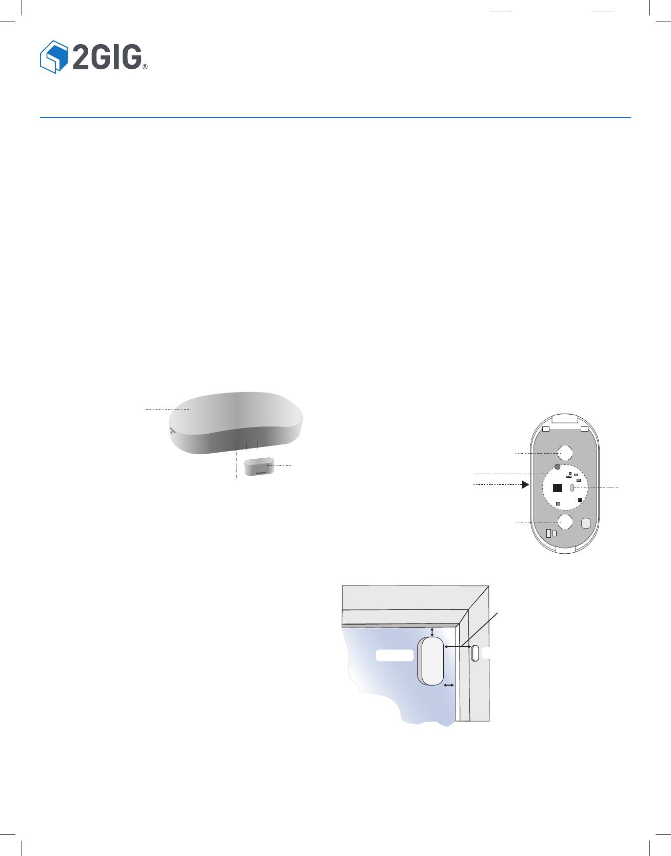
Figure 1. Shock/Door/Window Contact Sensor and Magnet
C
A
BB
A
A
D
CUnder Circuit Board
A Shock/Door/Window Contact Sensor
B Magnet alignment Marks on Sensor
C Shock/Door/Window Contact Magnet
A Screw mounting holes
(on backplate)
B Programming Button
C CR2450 Lithium battery
(under circuit board)
D Battery Access Slot
●1 — Shock/Door/Window Contact Sensor
●1 — Rare Earth Magnet
●2 — Phillips Head Mounting Screws
●1 — Lithium Coin Battery (Installed)
●2 — Adhesive Foam Tape (pre-applied on sensor and magnet)
●1 — Window Warning Sticker
Box Contents
Verify that the package includes the following:
Testing The Shock/Door/Window Contact Sensor
Before mounting the contact at the desired location, learn it into the
control panel. Then, perform a walk test utilizing a shock event as the
test transmission to verify that it can establish good Radio Frequency
(RF) communications with the control panel.
NOTE: To learn how to program and fully test the Shock/Door/Window
Contact Sensor, see the control panel’s Installation and Programming
Guide. For 2GIG panels using older irmware, this sensor may be
learned in as a D/W device. Newer panel firmwares will support
shock detector equipment code type 1066.
Mounting Guidelines
Use these guidelines when installing the sensor:
●Mount Sensors within 100 ft (30 m) of the Control Panel.
Although the transmitter may have a range of over 500 ft (150m)
open air, the sensor location can have a signicant effect on
range. In open/unobstructed situations, the transmitter range may
be greater. In adverse wireless conditions, changing the sensor
orientation may lead to improved range.
●Mount Sensors at Least 4.7 in (12 cm) Above the Floor. Placing
sensors slightly above oor level helps to minimize possible sensor
damage.
●Window Shock and Sliding Door/Window Installation: Mount
the Shock/Door/Window Contact Sensor on the xed pane window
1” from the frame for optimal performance. Place the sensor on the
moving section of the door/window and the magnet in a stationary
location. The included magnet must be within 2” of the sensor. If a
wider gap is required, up to 5”, use the optional DecoTrim Magnet
(p/n 2GIG-DECOTRIM).
●Do Not Expose Sensors to Moisture or Extreme Temperature.
It is best to mount sensors in a dry location where the operating
temperature does not exceed 0° to 130°F (-18° to 54°C).
●Keep Sensors and Magnets Away from Metal/Metallic
Surfaces. Keep sensors and magnets away from metal or metallic
surfaces (for example, foil). You should also avoid mounting
sensors in areas where there is a large quantity of metal or
electrical wiring (for example, near a furnace or in a utility room).
NOTE: Use on metal doors and windows with metal frames will
signicantly impair the performance of this sensor.
Mounting The Shock/Door/Window Contact Sensor
Use the gure below as a guideline when mounting the contact.
Figure 2. Backplate and Battery Compartment
1”
1”
Sensor Magnet
1 to 2”
Sensor: Install one inch
from the edge of the glass.
Magnet: Install 1 to 2
inches from the Sensor.
Figure 3. Standard Glass Mounting
To mount the Shock/Door/Window Contact Sensor:
Remove the backing form the pre-applied double-sided tape on the
bottom of the Sensor and place in the desired location.
NOTE: When mounting on a glass window, place the device one
inch from the top or bottom and side edge of the window.
2
Shock/Door/Window Contact | Installation Instructions
CONFIGURING THE SHOCK/DOOR/WINDOW
CONTACT SENSOR
The Sensor comes pre-congured to detect shock on a Glass door or
window. If the Sensor is to be mounted on a different surface or if the
integrated Magnetic Contact is to be used, it must be congured for
optimal performance. To congure the sensor:
1 Mount the sensor and magnet as described in this these
Installation Instructions.
2 If necessary, remove the cover by pressing in the Retaining Tab
and gently swinging the top of the Sensor off the base.
3 Remove the battery pull tab making sure that the battery stays
rmly in place.
NOTE: The LED should not be illuminated.
The program button may now be used to: Initiated by these button presses:
Review the Sensor Settings Press and release.
Set the Shock Sensor Sensitivity Press and hold until the LED blinks
once in Orange.
Enable/Disable Magnet Detection Press and hold until the LED blinks
Twice in Orange.
Restore the Factory Default settings Press and hold until the LED blinks
Three Time in Orange.
Review Sensor Settings
Press and hold the program button for less than 2 seconds:
● The Red LED will ash indicating the current shock sensor setting.
○ One ash represents the low sensitivity setting
○ Two ashes represents the medium sensitivity setting
○ Three ashes represents the high sensitivity setting
○ Four ashes represents the very high sensitivity setting
○ Five ashes represents the glass mount setting (Default)
● The Green LED then ashes indicating the Magnet Detection
setting:
○ One ash represents magnet detection has been enabled
○ Two ashes represents magnet detection has been disabled
(Default)
Setting the Shock Sensor Sensitivity
To accommodate different surface types and environmental situations
that may require more or less sensitivity in the detection of shock
events, ve selectable settings are available. To change the sensitivity
level from the default Glass Mount to another setting, press and hold
the program button for 2 to 5 seconds:
● Release the program button when the Orange LED ashes once
indicating that the sensor has entered this programming mode.
●Press the program button to select the new shock sensor setting
○One button press selects the low sensitivity setting
○Two button presses selects the medium sensitivity setting
○Three button presses selects the high sensitivity setting
○Four button presses selects the very high sensitivity setting
○Five button presses selects the glass mount setting (Default)
Each time the button is pressed the Red LED will illuminate until the
button is released.
NOTE: If the button is pressed six or more times such entries will
be ignored and the LED will remain off and the sensor will retain the
previous setting.
When the button has not been pressed for a period of ve seconds,
the programming mode will be exited and the Red LED will ash
indicating the programmed Shock Sensitivity.
Enable / Disable the Magnet Detection
The 2GIG-SHKDW1-345 can be used as a Door / Window transmitter.
The sensor is shipped with Magnet Detection disabled so this function
must be enabled and calibrated if the sensor is to be used as a door/
window contact sensor.
Begin by pressing and holding the program button for 5 to 10 seconds:
● Release the program button after the Orange LED ashes twice.
●Press the program button to enable or disable the magnet
detection capability.
○One button press enables magnetic detection
○Two button presses disables magnetic detection (Default)
Each time the button is pressed the Green LED will illuminate until the
button is released.
NOTE: If the button is pressed three or more times such entries will be
ignored and the and magnet detection default to the previous setting.
When the button has not been pressed for a period of ve seconds,
the programming mode will be exited and the Green LED will ash
indicating the programmed Shock Sensitivity.
2 If utilizing the integrated Door/Window capability, ensure that
the magnet is lined up with the middle mark on the sensor. See
“Calibrating Magnet Detection” on page 3 (see Figure 1 Shock/
Door/Window Contact Sensor and Magnet).
NOTE: To utilize the Magnetic Contact, the sensor must be congured
(see “Conguring the Shock/Door/Window Sensor” section on page 2).
3 Use the pre-applied adhesive tape to secure the magnet in place.
IMPORTANT: The magnet must be no more than 2.0” away from the
sensor. If a wider Gap is required, use the optional DecoTrim Magnet
(p/n 2GIG-DECOTRIM).
4 The sensor comes congured to mount on Glass with the Magnet
Detection disabled. If this is the desired operation, skip to “Finalizing
the Installation” section on page 3.
NOTE: If the shock sensor is being used on a door or wall, the
sensor’s sensitivity must be congured (see “Conguring the Shock/
Door/Window Sensor” section on page 2).
3
Shock/Door/Window Contact | Installation Instructions
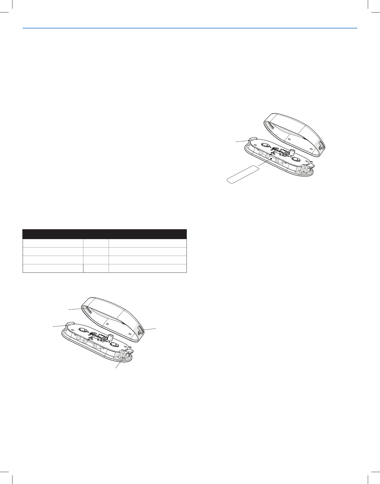
Inserting and Replacing the Batteries
To insert or replace the batteries:
1 Press in the Retaining Tab (A) and gently swing the top of the
sensor up and off the base.
2 Place a small non-metal object in the slot on the side of the sensor
(see Part C,D in Figure 2, Shock / Door / Window Contact and
Battery Compartment).
3 Carefully push the battery out through the Battery Access slot.
WARNING: Failure to follow these warnings and instructions can lead
to heat generation, rupture, leakage, explosion, re, or other injury, or
damage. Do not insert the battery into the compartment in the wrong
direction. Always replace the battery with the same or equivalent type.
Never recharge or disassemble the battery. Never place the battery in
re or water. Always keep batteries away from small children. If batter-
ies are swallowed, promptly see a doctor.
Restore Factory Settings
Press and hold the program button for more than 10 seconds:
●Release the program button after the Orange LED ashes three times.
● Press and release the program button once more to conrm that
factory defaults are to be restored. If this is not done within 5
seconds, the reset function will be terminated with no change to the
programmed settings.
The Red LED will ash as per the programmed shock sensor setting then
the Green LED will ash per the programmed Magnet Detection setting.
1 Tilt the cover to align tab C through slot D.
2 Close the cover down, and press down until tab A snaps into slot B.
Finalizing the Installation
A
B
D
C
Figure 4. Replacing Sensor Cover
A
N
on
-Met
a
l Obje
c
t
Figure 5. Remove/Replace Battery
Installer Test Mode
To enter Installer Test Mode, remove the top housing from the sensor.
In this mode the LED will blink to indicate specic conditions.
IMPORTANT: Always dispose and/or recycle used batteries in
accordance with the hazardous waste recovery and recycling
regulations for your location. Your city, state, or country may also
require you to comply with additional handling, recycling, and disposal
requirements.
1 Insert the replacement battery in the compartment. The positive (+)
sign on the battery should be facing down and the negative (–) side
facing up.
2 The Green LED will illuminate for 2 seconds as the Device powers up.
3 Replace the top case (see Finalizing the Installation, above).
Event LED Color Duration
Shock Detected Red ON for 8 seconds
Magnetic Detection Green Single Blink
Magnetic Tamper Orange Single Blink
Magnetic Calibration Required Red Double Blink
Shock Detection System Test - Glass Mounted
Firmly tap the glass twice with a hard plastic object (screwdriver
handle) within 12 inches of the sensor. Verify that the shock event
was received by the panel. It may take up to 2 seconds for the panel
to receive the notication.
NOTE: Do not strike the surface hard enough to break the glass.
Calibrating Magnet Detection
When magnetic detection is rst enabled, the RED LED will
blink to indicate that it is not calibrated. THE SENSOR MAGNET
CALIBRATION MUST BE COMPLETED TO OPERATE PROPERLY.
IF NOT CALIBRATED THE SENSOR WILL NOT TRANSMIT OPEN/
CLOSE INFORMATION TO THE CONTROL PANEL.
To calibrate the sensor:
1 Mount the sensor and magnet in it’s nal location as instructed
earlier in this document.
2 Close the door or window.
3 Press the Program button.
4 LED will start blinking ORANGE.
5 Open the door or window completely.
6 Press the Program button again.
7 LED will start blinking green
8 Fully close door or window and press the Program Button within
10 seconds to complete the calibration process..
9 LED will illuminate green for 2 seconds and then turn off and the
calibration is complete.
NOTE: If Magnet Detection is turned off then back on or if the battery
is removed or replaced, the sensor will lose the Magnet Calibration
setting and will have to be re-calibrated.
4
Shock/Door/Window Contact | Installation Instructions
Limited Warranty
This Nortek Security & Control LLC product is warranted against defects in
material and workmanship for two (2) years. This warranty extends only to
wholesale customers who buy direct from Nortek Security & Control LLC or
through Nortek Security & Control LLC’s normal distribution channels. Nortek
Security & Control LLC does not warrant this product to consumers.
Consumers should inquire from their selling dealer as to the nature of the
dealer’s warranty, if any.
There are no obligations or liabilities on the part of Nortek Security & Control
LLC for consequential damages arising out of or in connection with use or
performance of this product or other indirect damages with respect to loss of
property, revenue, or prot, or cost of removal, installation, or reinstallation.
All implied warranties for functionality, are valid only until the warranty expires.
This Nortek Security & Control LLC Warranty is in lieu of all other warranties
expressed or implied.
10021991 X8
Nortek Security & Control LLC | 2GIG
For technical support in the USA and Canada:
855-2GIG-TECH (855-244-4832)
Email: 2gigtechsupport@nortekcontrol.com
Visit www.nortekcontrol.com for technical support hours of operation.
For technical support outside of the USA and Canada:
Contact your regional distributor.
Visit www.2gig.com/dealers/ for a list of distributors in your region.
REGULATORY INFORMATION
FCC & IC Notice
This device complies with Part 15 of the FCC Rules and Industry Canada
license exempt standard(s). Operation is subject to the following two conditions:
1. This device may not cause harmful interference, and
2. This device must accept any interference received, including interference
received that may cause undesired operation.
1. l’appareil ne doit pas produire de brouillage, et
2. l’utilisateur de l’appareil doit accepter tout brouillage radioélectrique subi,
même si le brouillage est susceptible d’en compromettre le fonctionnement.
This Class B digital apparatus complies with Canadian ICES-003 Cet appareil
numérique de la classe B est conforme à la norme NMB-003 du Canada.
This equipment has been tested and found to comply with the limits for a
Class B digital device, pursuant to Part 15 of the FCC Rules. These limits are
designed to provide reasonable protection against harmful interference in a
residential installation.
This equipment generates, uses, and can radiate radio frequency energy and,
if not installed and used in accordance with the instructions may cause
harmful interference to radio communications. However, there is no
guarantee that interference will not occur in a particular installation. If this
equipment does cause harmful interference to radio or television reception,
which can be determined by turning the equipment off and on, the user is
encouraged to try to correct the interference by one or more of the following
measures:
WARNING:
Changes or modications not expressly approved by the manufacturer could
void the user’s authority to operate the equipment.
SPECIFICATIONS
Wireless Signal Range 500 ft ( 152 m), open air, with Wireless
Control Panel
Code Outputs Alarm; Alarm Restore; Supervisory;
Low Battery; Tamper; Tamper Restore
Transmitter Frequency 345.00 MHz
Supervisory Interval 70 minutes
Status Messages Shock - Loop 1
Door/Window - Loop 2
Magnet Dimensions
(L x W x H) 0.91 x 0.47 x 0.35 in (23 x 12 x 9 mm)
Magnet Type Rare Earth
Sensor Dimensions (L x W x H) 3.11 x 1.46 x 0.67 in (79 x 37 x 17 mm)
Weight Sensor - 1.12 oz
Magnet - 0.32 oz
Housing Material PC-ABS Plastic
Color White
Operating Temperature 0° to 130°F (-18° to 54°C)
Relative Humidity 5-95% Non-Condensing
Battery (included) One (1) CR2450 Lithium batteries
Equipment Code 1066 - 2GIG Shock Sensor.
Certication ETL, FCC, IC
Copyright © 2018 Nortek Security & Control LLC
• Reorient or relocate the receiving antenna.
• Increase the separation between the equip ent and receiver
• Connect the equipment into an outlet on a circuit different from that to
which the receiver is
connected
• Consult the dealer or an experienced radio/TV technician to help.
We, Nortek Security & Control LLC of 5919 Sea Otter Place, Carlsbad, CA
92010, declare under our sole responsibility that the device, EUT MODEL#
complies with Part 15 of the FCC rules.