Nortek Security and Control DXS14 Security Alarm Transmitter User Manual 233762 X2 DXS 14 Installation Instructions indd
Nortek Security & Control LLC Security Alarm Transmitter 233762 X2 DXS 14 Installation Instructions indd
Users Manual
DXS-14
SUPERVISED
REMOTE
KEYPAD
Operating Instructions
ALARMFORCE
AlarmForce Industries Inc.
675 Garyray Drive
Toronto, ON M9L 1R2, Canada
PRINTER’S INSTRUCTIONS:
INSTR,INSTL,DXS-14 - LINEAR P/N: 233766 X3 - INK: BLACK - MATERIAL: 20 LB. MEAD BOND - SIZE: 5.500” X 8.500” - SCALE: 1-1 - FOLDING: ALBUM FOLD - BINDING: SADDLE-STITCH
2
KEYPAD OVERVIEW
The LCD Supervised Remote Keypad adds remote control to Alarm Force
Security System Panels. The wireless keypad transmits key presses to the
panel and displays alphanumeric data received from the panel.
A press of any key puts the keypad in a fully operational mode with backlit
LCD and RF Transceiver active. After 15 seconds of inactivity the keypad
will return to the standby mode unless tones are being generated. If tones
are required, then the keypad will enter standby mode only when tone
cycles have been completed.
The keypad can be wall mounted and is powered by four 1.5 volt AA
batteries. The batteries will operate the keypad for three years based
on two minutes of operation per day. If the AA batteries become low, the
keypad will send low battery reports to the panel. The keypad will continue
to operate for 3 months after the fi rst low battery report.
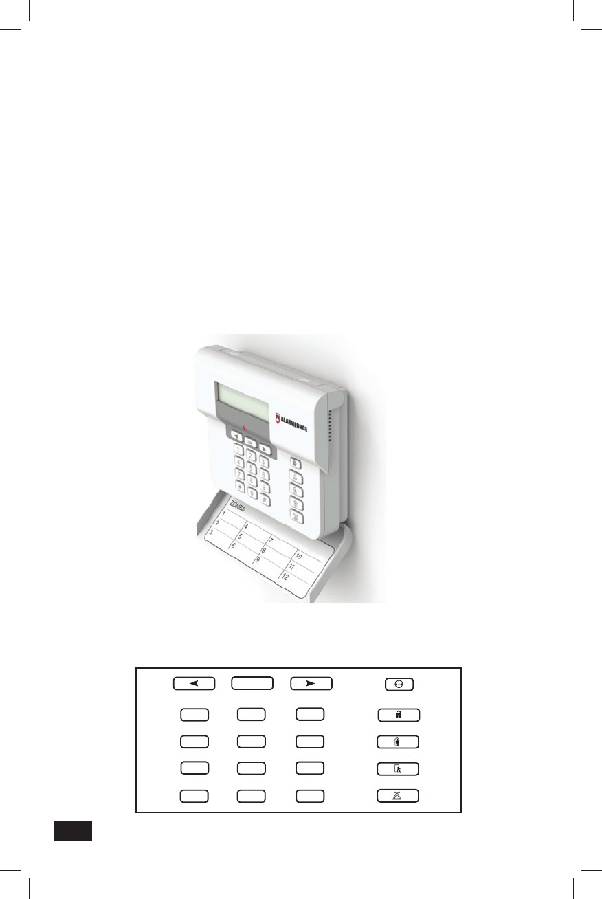
KEYPAD RESOURCES
The keypad consists of 20 silicone rubber keys. The keys are backlit
making it visible in low light conditions.
OK
123
456
789
0
*#

3
REAL TIME CLOCK
The keypad has a real time clock (RTC) that must be set during installation
and after battery replacement. The RTC is required for the keypad to
display time- and date-stamped events, using time offset data received
from the panel. Time and date are also shown during the keypad status
display when the keypad fi rst wakes up:
KEYPAD READY
28/07/2011 12:45AM
Depending on the country/language selected, the time and date format is:
French and Spanish display:
DD/MM/YYYY HH:MM (24 hour time) -- default
US/English display:
MM/DD/YYYY HH:MM (AM/PM)
RTC time and date are set locally at the keypad from the keypad
confi guration menu. A confi guration setting is also provided to manually
turn on Daylight Saving Time (advances or sets back time by 1 hour).
A “clock” key is provided for local keypad operation and confi guration:
• Pressing the clock key once displays the keypad status and time and date on the LCD.
• Pressing and holding the clock key for more than 1 second displays the time and date setting
on the LCD (fl ashing digits), which can then be set using the numbers (0-9) and navigation
keys ( ) on the keypad.
• Pressing the clock key again provides the setting for Daylight Saving Time (DST) on/off.
• Pressing OK toggles between AM-PM, DST ON-OFF
• Pressing the clock key once more exits keypad set-up mode and resumes normal operation.
LCD
The keypad has a two line, twenty characters LCD display. The display is
backlit with LEDs for low light conditions.
The LCD display text is controlled by commands from the panel. The
keypad will also display information on the LCD upon wake-up (“keypad
status”) and in response to certain key press combinations.
The LCD is capable of displaying over 200 characters and symbols.

4
Autonomous Keypad Commands and User Prompts
In most operations, the keypad will only send key presses to the panel and
in response the panel will update the display, LED and tone annunciations
as needed to refl ect the current state of the system.
When doing an initial installation or manually activated program updates
the keypad will function autonomously and provide user prompts without
intervention by the panel.
Entering autonomous keypad command operation: When the keypad
detects the long press *, it will display the following user prompt on the
2-line LCD display:
SPECIAL COMMAND
<-- TOGGLE CHIME -->
A long press * key press message is sent to the panel at this time. At
this point, the panel may respond to disallow the operation of special
commands if special commands are disabled. The keypad will display the
reason the command is disallowed and abort the autonomous command
mode:
SPECIAL COMMANDS DISABLED
Alarm history
The alarm history command is serviced by the ARM DISPLAY message
packet. Up to 5 alarm events are sent from the panel to the keypad in a
single message packet. These events are displayed one event at a time
on the LCD. The user may scroll through these events by pressing the
keys. Pressing OK exits the display (and autonomous command
operation).
Display example with 3 alarm events:
07/22/11 1:55PM
ZONE 32 ALARM -->
07/20/11 11:55AM
<-- ZONE 21 ALARM -->
06/17/11 12:55AM
<-- ZONE 32 ALARM

5
Arming history
The arming history command is serviced by the ARM DISPLAY message
packet. Individual arm or disarm events are sent from the panel to the
keypad in a single message packet; if arming, any bypassed zones are
also included (up to 15) in the same message packet. These events are
displayed one event at a time on the LCD. The user may scroll through
these events and bypassed zones by pressing the keys.
When viewing the last event in the list, pressing the key when displaying
an event with no bypassed zones or the last bypassed zone listed will
cause the keypad to send the key press to the panel, which in turn will
provide a DISPLAY ARM message packet for the next event in the panel’s
arming history.
When viewing the fi rst event in the list, pressing the key when displaying
an arm or disarm event will send the key press to the panel, which will
provide a DISPLAY ARM message packet for the previous event in the
panel’s arming history.
Pressing OK exits the display (and autonomous command operation).
Display example with 3 arming events, the fi rst one with two bypassed
zones:
07/22/11 6:55AM
KFOB 05 ARM AWAY -->
07/22/11 6:55AM
<-- BYPASS ZONE 05 -->
07/22/11 6:55AM
<-- BYPASS ZONE 08 -->
07/22/11 9:55PM
<-- USER 05 ARM HOME -->
07/20/11 5:30PM
<-- USER 05 DISARMED

6
Keypad Low Battery
The keypad communicates a low battery condition to the panel through
the low battery bit set in the KEY PRESS message. If the battery is low,
on keypad wake up the keypad will indicate a fault condition (beep and
fl ash the LED red once) while briefl y displaying on the LCD a low battery
prompt, instead of the usual keypad ready message:
PLEASE REPLACE
KEYPAD BATTERIES
Once the low battery condition occurs, key presses will also be annunciated
by a double click instead of the usual single click.
If the battery condition continues to deteriorate to marginal levels, the
keypad may take measures to conserve power by limiting backlight
operation or reducing inactivity timeout before going into standby.
Communication Failure
If the keypad is unable to communicate with the panel during operation
and receives a RETRY FAIL message from its transceiver, it will indicate
a fault condition (beep and fl ash the LED red once) and display a prompt
to the user:
PLEASE RE-ENTER
KEY SEQUENCE
If the keypad is active and the condition persists for more than 15
seconds, the keypad will repeat the fault indication. This will recur until
the communication is restored or until the keypad times out and goes into
standby mode.
Piezo Annunciator
The keypad has a piezo sounder to indicate system conditions to the user.
A short beep will occur every time a key is pressed. In addition, commands
from the panel will instruct the sounder to operate in a specifi ed pattern.
Bicolor LED
The keypad has a red / green LED controlled by commands from the panel.

7
KEYPAD WIRELESS SYSTEM
The keypad has a wireless transceiver module that communicates with the
microprocessor via a serial UART. The internal antenna is used for both
transmit and receive functions. The transceiver module is mounted in a
shielded enclosure for RFI protection.
RF Transceiver Specifi cations
The transceiver complies with FCC Part 15 and ISC Canada RSS-210 requirements.
Frequency 433.92MHz ±43.4 KHz (100 ppm)
Receive and Transmitt
Receiver Image Rejection 30 dB
L.O. Re-Radiation Meets FCC Part 15 and ISC Canada
Dynamic Range 85 dB
RF Encoding Format Proprietary format
RF Input Single integral antenna
Power Input 3.0-3.3 VDC regulated supply 100 mA
Operating Temperature Range -10 °C to +60 °C
Antenna 2 insulated wires approximately 6.5”
MECHANICAL
Material Cases molded in ABS plastic
Mounting Wall mounting
Battery Access 4 AA Batteries are replaceable by removing
keypad from wall mounting bracket. There is no
access to the electronics when replacing
batteries.
Miscellaneous The silicone keypad is covered by a door
that can be swung out of the way for access to
the keypad. In addition the door can be
removed by user if desired. An opening in the
case is provided for a piezo sounder and
bi-color LED.
MISCELLANEOUS REQUIREMENTS
Environmental Operating Temperature 32°-120° F (0-49° C)
Regulatory IC/ Industry Canada, FCC (Part 15)
Power 4 AA batteries supply power and are included.
The keypad battery life is three years based on
two minutes of operation per day. The batteries
are user replaceable.
Mounting Hardware Screws and anchors for standard wall
mounting are included.

FCC / IC COMPLIANCE STATEMENT
This device complies with FCC Rules and Regulations as Part 15 Rules and Regulations
and Industry Canada license exempt RSS standards. Operation is subject to the following
two conditions: 1.This device may not cause harmful interference and 2. This device
must accept any interference received, including interference that may cause undesired
operation.
Le présent appareil est conforme aux CNR d’Industrie Canada applicables aux appareils
radio exempts de licence. L’exploitation est autorisée aux deux conditions suivantes : (1)
l’appareil ne doit pas produire de brouillage, et (2) l’utilisateur de l’appareil doit accepter tout
brouillage radioélectrique subi, même si le brouillage est susceptible d’en compromettre
le fonctionnement.
This equipment has been tested and found to comply with the limits for a Class B digital
device, pursuant to part 15 of the FCC Rules. These limits are designed to provide reasonable
protection against harmful interference in a residential installation. This equipment
generates, uses and can radiate radio frequency energy and, if not installed and used in
accordance with the instructions, may cause harmful interference to radio communications.
However, there is no guarantee that interference will not occur in a particular installation. If
this equipment does cause harmful interference to radio or television reception, which can
be determined by turning the equipment off and on, the user is encouraged to try to correct
the interference by one or more of the following measures:
—Reorient or relocate the receiving antenna.
—Increase the separation between the equipment and receiver.
—Connect the equipment into an outlet on a circuit different from that to which the
receiver is connected.
—Consult the dealer or an experienced radio/TV technician for help.
IMPORTANT INFORMATION ABOUT RADIO DEVICES
1. AlarmForce radio controls provide a reliable communications link and fi ll an
important need in portable wireless signaling. However, there are some limitations
which must be observed.
2. For US installations only: the radios are required to comply with FCC rules and
regulations including FCC part 15 devices. As such, they have limited transmitter
power and therefore limited range.
3. A receiver cannot respond to more than one transmitted signal at a time and
may be blocked by radio signals that occur on or near their operating frequencies
regardless of code settings.
4. Changes or modifi cations to the device not expressly approved by AlarmForce
could void the authority to operate the equipment.
5. Infrequently used radio links should be tested regularly to protect against
undetected interference or fault.
6. RF signals can be affected by metal objects including metal doors or large mirrors.
Care should be taken to avoid these objects during installation as they can interfere
with proper operation.
233766 X3Copyright © 2012