Nortek Security and Control PIR319 Wireless Motion Sensor User Manual 187 1132B indd
Nortek Security & Control LLC Wireless Motion Sensor 187 1132B indd
Users Manual
NAPPIR01
SUPERVISED WIRELESS
MOTION DETECTOR
With Pet Immunity
Installation Instructions
PRODUCT DESCRIPTION
The NAPPIR01 is a battery powered passive infrared motion detector with a built-in transmitter designed for
use with NAPCO® GEM and GEM-C systems. This transmitter can be used in a variety of motion detection
applications. When the passive infrared sensor detects motion in its fi eld of view, the transmitter sends a digitally
coded wireless signal to its companion receiver. To reduce false alarms caused by pets inside the protected area,
the NAPPIR01 features pet immunity with a selectable large or small pet setting.
The NAPPIR01 can send fi ve different signals: fault, restore, low battery, status, and tamper. Receivers must be
programmed to the transmitter’s code before system testing and operation. Refer to the receiver’s instructions for
details on programming.
In a typical installation, the motion detector is mounted indoors in a corner or on a wall 7-1/2 feet high. Two
mounting brackets and an adjustable PIR bracket are included. The sensor will monitor the infrared level in its
detection pattern. If the level increases or decreases rapidly (as when a person moves through the area) the
transmitter triggers, sending a fault signal to the receiver. A restore signal is sent when the motion stops. To
conserve battery life, during normal operation, the detector can trigger the transmitter a maximum of once every
three minutes. Opening the transmitter case will send a tamper signal.
Being supervised, about every 65 minutes the transmitter sends a status signal to update the panel. If the battery
tests low, a low battery signal is included with any transmission. The transmitter is powered from one 3-Volt
CR123A lithium battery (included).
For setup and testing, pressing the test button on the left side of the case places the unit in walk test mode for fi ve
minute. The installer can walk in front of the unit while viewing the red test indicator through the detector’s lens to
determine the detection area.
The detector can be mounted directly to the wall, or by using the PIR mounting bracket assembly. The assembly
connects the PIR to the corner or wall mount bracket and allows vertical and horizontal adjustment of the unit.
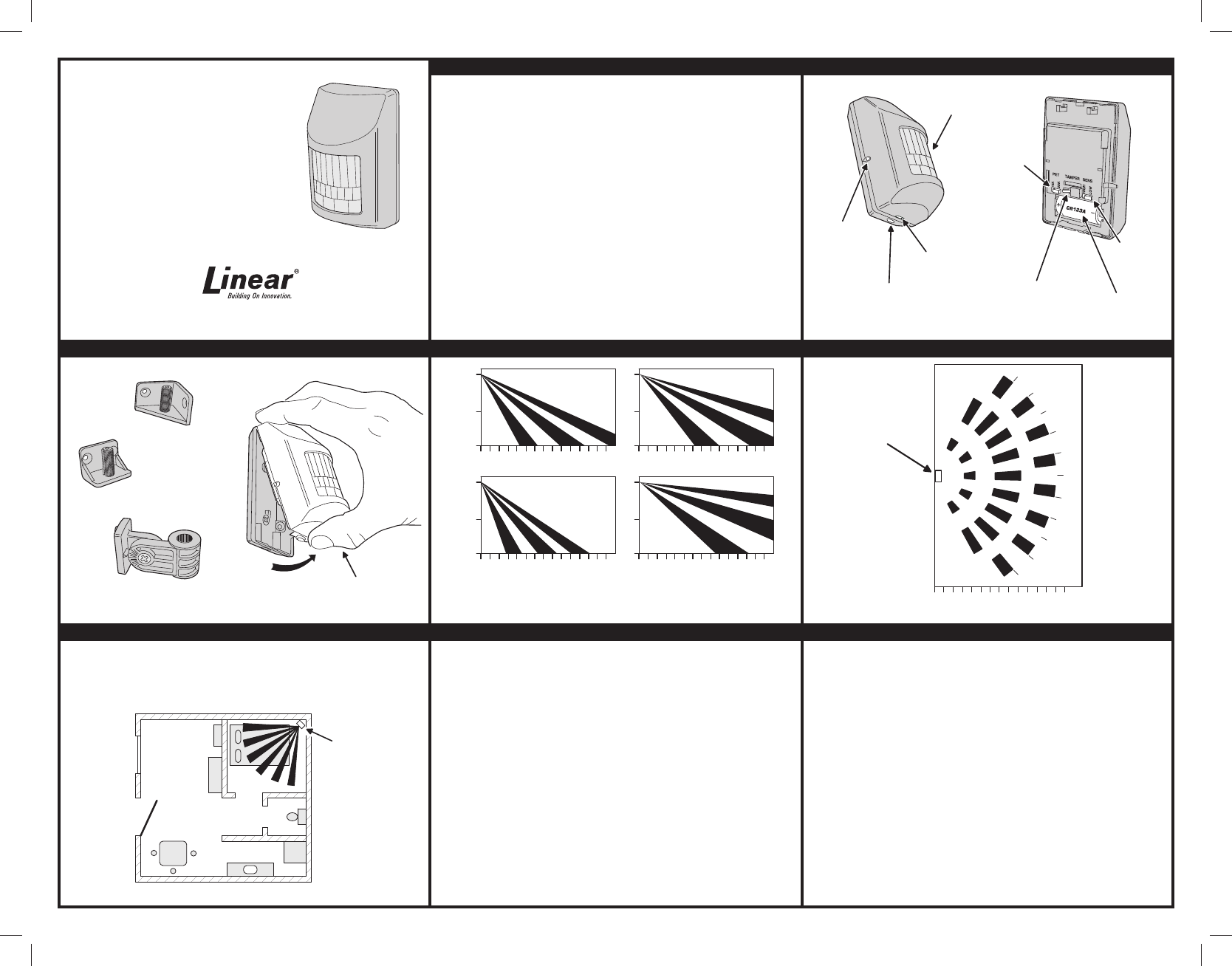
PIR FEATURES
INSTALLATION BRACKETS DETECTION PATTERN SIDE VIEW DETECTION PATTERN TOP VIEW
TYPICAL INSTALLATION PIR INSTALLATION TIPS PIR INSTALLATION TIPS
USA & Canada (800) 421-1587 & (800) 392-0123
(760) 438-7000 - Toll Free FAX (800) 468-1340
www.linearcorp.com
PRINTER’S INSTRUCTIONS:
INSTR,INSTL,NAPPIR01 - P/N:187-1132 AX1 - INK: BLACK - MATERIAL: 20 LB. MEAD BOND - SIZE: 11.000” X 8.500” - SCALE: 1-1 - SIDE 1 OF 2
WALK TEST
BUTTON
PIR
LENS
CASE
LOCKING
BUTTTON
15K - 25K
PET IMMUNITY
PET SIZE JUMPER
TAMPER SWITCH
HIGH - LOW
SENSITIVITY
JUMPER
CR123A 3-VOLT
LITHIUM BATTERY
CASE
ACCESS
SLOT
WALL MOUNTING
BRACKET
CORNER
MOUNTING
BRACKET
ADJUSTABLE PIR
MOUNTING BRACKET
SQUEEZE TOP AND BOTTOM
OF CASE TO OPEN
7.5
3.75
0
036 9 12 15 1821 24 27 3033 363940
-9
°
7.5
3.75
0
036 9 12 15 1821 24 27 3033 363940
0
°
7.5
3.75
0
036 9 12 15 1821 24 27 3033 363940
-18
°
7.5
3.75
0
036 9 12 15 1821 24 27 3033 363940
+9
°
0° IS THE PIR FACING THE OPPOSITE WALL WITH NO TILT
-9° IS THE PIR TILTED DOWN ONE CLICK
-18° IS THE PIR TILTED DOWN TWO CLICKS
+9° IS THE PIR TILTED UP ONE CLICK
ALL UNITS ARE IN FEET 036 9 12 15 1821 24 27 3033 363942
50
°
40
°
30
°
20
°
10
°
0
°
10
°
20
°
30
°
40
°
50
°
DISTANCE FROM PIR IN FEET
PIR LOCATION
DON'T POINT AT HEAT SOURCES
(HEATERS, ETC.), WINDOWS, OTHER
MOTION DETECTORS OR DOOR/WINDOW
TRANSMITTERS
BEDROOM
BATH
KITCHEN
FRONT
ROOM
(FOR INDOOR
USE ONLY)
MOUNT
DETECTOR
SO THAT
INTRUDER
WILL CROSS
BEAMS
PIR
MOTION
DETECTOR
While the NAPPIR01 is a highly reliable intrusion detection device, it does not offer guaranteed protection against
burglary. Any intrusion detection device is subject to compromise or failure to warn for a variety of reasons. The
following issues should be considered during new installations or when troubleshooting:
• If the premise has pets, make sure to follow the instructions in this manual concerning installation with pets.
• This PIR has built-in protection, which keeps bugs from getting into the sensor area and causing false
alarms. This does not prevent insects from crawling across the lens of the PIR, which in turn can cause the
PIR to trigger an alarm.
• Infrared energy can be refl ected off any glossy surface such as mirrors, windows, fl oors or counter tops with
glossy fi nish, and slick fi nished concrete. Some surfaces will refl ect less than others will. For example, PIRs
can see a change in infrared energy refl ected off any refl ective surface even if the heat or cold source is not
within the detection pattern of the PIR.
• Windows cannot only refl ect infrared energy, but they can also allow sunlight or lights from cars to pass
through to the PIR. For example, a PIR can detect a quick change in infrared energy if sun light comes
through a window (which may not be detected by the PIR) and shines on a hardwood fl oor (which can be
detected by the PIR). If the change in infrared energy is quick enough on the fl oor, the PIR can trigger an
alarm. The same applies if the PIR “covers” the window, even though the pattern of protection cannot “see”
through glass. Lights from a passing car can also pass through the window at night and directly into the lens
of the detector.
• Heating and A/C ducts are also important to take into consideration because if they blow air onto an object
within the fi elds of view, the temperature of that object could change quickly enough for the detector to see
a change in infrared energy. Detectors cannot see air current, only the change in temperature of a physical
object.
• The PIR senses change in temperature; however, as the ambient temperature of the protected area
approaches the temperature range of 95° to 120°F, the detection performance can decrease.
• Make sure the area you wish to protect does not have obstructions (curtains, screens, large pieces of
furniture, plants, etc.) that may block the pattern of coverage provided by the PIR.
• Anything that can sway or move due to air current can cause a change in infrared energy within the fi elds
of view. Heating and A/C ducts, drafts from doors or windows can cause this to happen. Other objects to be
aware of are curtains, blinds, balloons, loose paper, plants, hanging banners or baskets, etc.
• Make sure the PIR is mounted on a solid surface and does not allow for any vibration. Vibration will not only
cause the PIR to move a little, but this will also cause the fi elds of view in the room to move with respect to
the PIR. A little vibration can go a long way with the fi elds of view, thus the PIR may see a change in energy.
• An installation may require a PIR to be aimed at a door. The PIR may “detect” door movement before the
door contact can initiate an entry delay, causing the PIR to trigger an alarm. If the PIR has to be installed this
way, it is recommended that the alarm control panel program set the PIR as an entry delay.
• The PIR detects intrusion only within the pattern of coverage as diagrammed in this manual.
• The PIR does not provide volumetric area protection.
• The PIR creates multiple beams of protection and intrusion can only be detected in unobstructed areas
covered by those beams.
• The PIR cannot detect motion or intrusion that takes place behind walls, ceilings, fl oors, closed doors, glass
partitions, glass doors, or windows.
• Tampering with, masking, painting, or spraying of any material on the PIR lens or any part of the optical
system can reduce the detection ability of the PIR.
• The PIR will not operate without the appropriate battery installed, or if the battery is weak or improperly
connected (i.e., reversed polarity).
• The PIR, like other electrical devices, are subject to component failure. Even though the NAPPIR01 is
designed to last as long as 10 years, the electronic components in it could fail at any time.
Copyright © 2013 Linear Corporation 187-1132 AX1
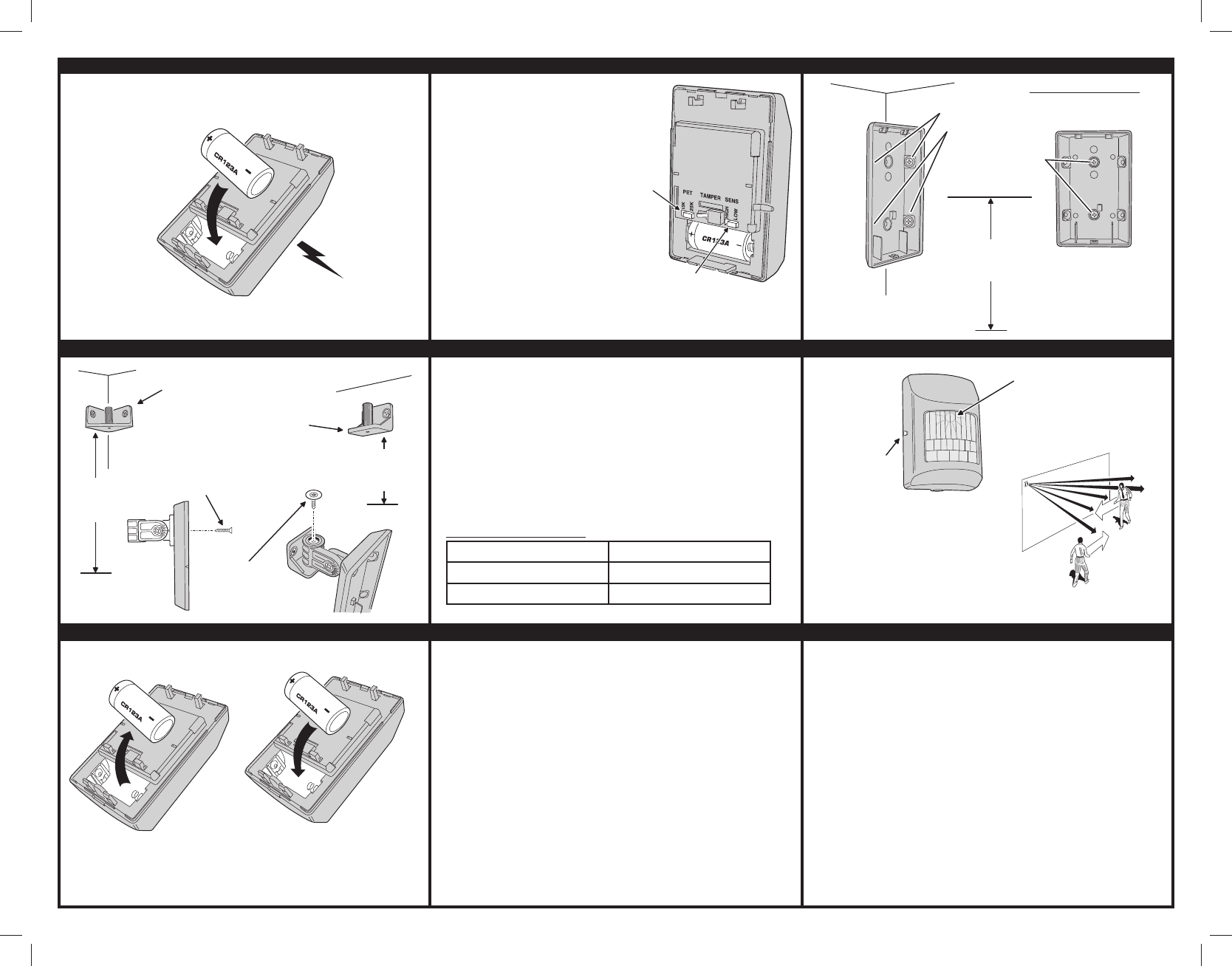
BATTERY INSTALLATION & PROGRAMMING PET IMMUNITY TIPS MOUNTING PIR WITHOUT INSTALLATION BRACKETS
MOUNTING PIR WITH INSTALLATION BRACKETS PROGRAMMING WALK TESTING AND OPERATIONAL TESTING
BATTERY REPLACEMENT SPECIFICATIONS LINEAR LIMITED WARRANTY
This Linear product is warranted against defects in material and workmanship for twelve (12) months. This
warranty extends only to wholesale customers who buy direct from Linear or through Linear’s normal
distribution channels. Linear does not warrant this product to consumers. Consumers should inquire from
their selling dealer as to the nature of the dealer’s warranty, if any. There are no obligations or liabilities on the
part of Linear LLC for consequential damages arising out of or in connection with use or performance
of this product or other indirect damages with respect to loss of property, revenue, or profi t, or cost of
removal, installation, or reinstallation. All implied warranties, including implied warranties for merchantability
and implied warranties for fi tness, are valid only until the warranty expires. This Linear LLC Warranty is in lieu
of all other warranties express or implied.
All products returned for warranty service require a Return Product Authorization Number (RPA#). Contact Linear
Technical Services at 1-800-421-1587 for an RPA# and other important details.
IMPORTANT !!!
Linear radio controls provide a reliable communications link and fi ll an important need in portable wireless
signaling. However, there are some limitations which must be observed.
• For U.S. installations only: The radios are required to comply with FCC Rules and Regulations as Part 15
devices. As such, they have limited transmitter power and therefore limited range.
• A receiver cannot respond to more than one transmitted signal at a time and may be blocked by radio signals
that occur on or near their operating frequencies, regardless of code settings.
• Changes or modifi cations to the device may void FCC compliance.
• Infrequently used radio links should be tested regularly to protect against undetected interference or fault.
• A general knowledge of radio and its vagaries should be gained prior to acting as a wholesale distributor or
dealer, and these facts should be communicated to the ultimate users.
PRINTER’S INSTRUCTIONS:
INSTR,INSTL,NAPPIR01 - P/N:187-1132 AX1 - INK: BLACK - MATERIAL: 20 LB. MEAD BOND - SIZE: 11.000” X 8.500” - SCALE: 1-1 - SIDE 2 OF 2
PET SIZE
JUMPER
15K = 33 LBS.
25K = 55 LBS.
SENSITIVITY
JUMPER
USE LOWEST
SETTING FOR
MAXIMUM
PET WEIGHT
ALWAYS SET
TO LOW FOR
PETS
To take full advantage of the NAPPIR01 pet
immunity features in installations with pets, use
these following steps:
• Mount the PIR with the center of the lens 7-1/2
to 8 feet above fl oor level.
• Set the SENSITIVITY jumper to the LOW
position.
• Set the PET SIZE jumper to the lowest setting
for the maximum pet weight.
• Mount the PIR where pets cannot come within
six feet of the unit by climbing on furniture,
boxes, or other objects.
• Do not aim the PIR at stairs or furniture, boxes,
or other objects that can be climbed by pets.
• NOTE: The NAPPIR01 will provide immunity
to false alarms for an individual animal or a
group of animals whose total weight is equal
to or less than 55 pounds when the room
temperature is above 50° F and below 90° F.
If the optional mounting bracket is used, it
should be mounted with no tilt.
OBSERVE BATTERY POLARITY!!!
PREPARE THE RECEIVER TO
"LEARN" THE TRANSMITTTER
WHEN THE RECEIVER IS READY,
INSTALL THE CR123A 3-VOLT
LITHIUM BATTERY AS SHOWN
PIR WILL SEND A TRANSMISSION
TO THE RECEIVER AND THE
TRANSMITTER'S ID WILL
BE STORED IN THE RECEIVER
CORNER MOUNTING
WITH CORNER
BRACKET
7.5 FEET
ABOVE THE
FLOOR
7.5 FEET
ABOVE THE
FLOOR
WALL MOUNTING
WITH WALL
BRACKET
ATTACH REAR OF
CASE TO THE
PIR BRACKET
- OR -
SECURE PIR
BRACKET WITH
SCREW AND WASHER
7.5 FEET
ABOVE THE
FLOOR
CORNER MOUNT
REAR CASE WITH
FOUR SCREWS
- OR -
WALL MOUNT
REAR CASE
WITH TWO
SCREWS
PRESS WALK TEST
BUTTON ON LEFT
SIDE OF CASE
RED WALK TEST INDICATOR
WILL SHOW THROUGH PIR LENS
UNIT WILL STAY IN
WALK TEST MODE
FOR FIVE MINUTES
WALK ACROSS BEAM PATTERN
WHILE OBSERVING THE
WALK TEST INDICATOR
SNAP CASE
CLOSED BEFORE
WALK TESTING
AFTER WALK TESTING, TEST
THE PIR WITH THE SYSTEM
CONTROL PANEL OR RECEIVER
OUTPUTS: FAULT, RESTORE, LOW BATTERY, STATUS, & TAMPER
TRANSMITTER FREQUENCY: 319.5 MHz
SUPERVISORY INTERVAL: 65 MINUTES
SENSOR TYPE: QUAD ELEMENT
PET IMMUNITY: SELECTABLE: 15 Kg (33 LBS.) OR 25 Kg (55 LBS.)
SENSITIVITY JUMPER: SELECTABLE: HIGH OR LOW
SUGGESTED MOUNTING HEIGHT: 7.5 FT. (2.3 m)
SENSOR RANGE: 30 FT. (9.1 m) X 50 FT. (15.2 m)
MAXIMUM HORIZONTAL SENSING ANGLE: 90°
DIMENSIONS: 3.2” x 2.5” x 1.9” (8.12 x 6.35 x 4.82 cm)
WEIGHT (INCLUDING BATTERY & BRACKET): 3.7 OZ. (104.9 g)
COLOR: WHITE
OPERATING TEMPERATURE: 32° TO 103° F (0° TO 39° C)
RELATIVE HUMIDITY: 5-95% NON-CONDENSING
BATTERY (INCLUDED, NOT INSTALLED): ONE (1) PANASONIC CR123A,
OR EQUIVALENT LITHIUM BATTERY
REGULATORY LISTINGS: FCC PART 15, INDUSTRY CANADA
INCLUDED ACCESSORIES: MOUNTING BRACKETS AND SCREWS, PLASTIC
WALL ANCHORS
THIS DEVICE COMPLIES WITH FCC RULES AND REGULATIONS AS PART 15 DEVICES, AS WELL AS INDUSTRY
CANADA RULES AND REGULATIONS. OPERATION IS SUBJECT TO THE FOLLOWING TWO CONDITIONS: (1) THIS
DEVICE MAY NOT CAUSE HARMFUL INTERFERENCE; (2) THIS DEVICE MUST ACCEPT ANY INTERFERENCE
RECEIVED, INCLUDING INTERFERENCE THAT MAY CAUSE UNDESIRED OPERATION.
Le présent appareil est conforme aux CNR d’Industrie Canada applicables aux appareils radio exempts de licence.
L’exploitation est autorisée aux deux conditions suivantes : (1) l’appareil ne doit pas produire de brouillage, et (2) l’utilisateur
de l’appareil doit accepter tout brouillage radioélectrique subi, même si le brouillage est susceptible d’en compromettre le
fonctionnement.
INSTALL CR123A 3-VOLT
LITHIUM BATTERY AS SHOWN
OBSERVE
BATTERY
POLARITY!!!
WHEN THE SYSTEM INDICATES THAT THE
PIR HAS A LOW BATTERY, REMOVE THE
OLD BATTERY AND DISPOSE OF IT PROPERLY
WARNING!
IMPROPER HANDLING OF LITHIUM
BATTERIES MAY RESULT IN HEAT
GENERATION, EXPLOSION OR FIRE ,
WHICH MAY LEAD TO PERSONAL
INJURIES. REPLACE WITH ONLY
TYPE CR123A BATTERY.
WARNING!
BATTERY MUST NOT BE RECHARGED,
DISASSEMBLED, OR DISPOSED OF
IN A FIRE. DISPOSAL OF USED BATTERIES
MUST BE MADE IN ACCORDANCE WITH THE
WASTE RECOVERY AND RECYCLING
REGULATIONS IN YOUR AREA.
WARNING!
KEEP BATTERY AWAY FROM SMALL
CHILDREN. IF BATTERY IS SWAL-
LOWED, PROMPTLY SEE A DOCTOR
CALIFORNIA ONLY: THIS PERCHLORATE WARNING
APPLIES ONLY TO MANGANESE DIOXIDE LITHIUM
CELLS SOLD OR DISTRIBUTED ONLY IN CALIFOR-
NIA, USA. PERCHLORATE MATERIAL: SPECIAL
HANDLING MAY APPLY,
SEE: www.dtsc,ca,gov/hazardouswaste/perchlorate.
For a detail programming guide, the instruction manual should be consulted for
that panel. The below guide should only be used as a reference and not as a
replacement for using the programming instructions.
1. Enter Panel Programming
2. Select Zone #
3. Enter 6 Digit ID number (located on back of unit)
4. Enter Check sum (0-9 ; A-F) (located on back of unit). Digit that follows ¨:¨ on
the Serial ID. For A - F use 0 - 5 (See Below)
5. Enter Point ¨3¨ - for PIR
6. Push On/Off to Save
Alpha Numeric Conversion
A = *0 D = *3
B = *1 E = *4
C = *2 F = *5
NOTE: LET PIR STAND WITH NO INTERFERENCE FOR
FIRST 3 MINUTES.