Nortek Security and Control RFI00002 FRS Radio Transceiver User Manual 214601A INDD
Nortek Security & Control LLC FRS Radio Transceiver 214601A INDD
Users Manual
WIRELESS INTERCOM SYSTEM
5-CHANNEL
RADIO INTERCOM
Installation & Operation Instructions
(760) 438-7000 • FAX (760) 438-7043
USA & Canada (800) 421-1587 & (800) 392-0123
Toll Free FAX (800) 468-1340
www.linearcorp.com
PRINTER’S INSTRUCTIONS:
INSTRL,INSTL,RI-C - LINEAR P/N: 214601 X1 - INK: BLACK - MATERIAL: 20 LB. MEAD BOND - SIZE: 8.500” X 5.500” - SCALE: 1-1 - FOLDING: ALBUM FOLD - BINDING: SADDLE-STITCH
214601 X1 - IMAGE 1

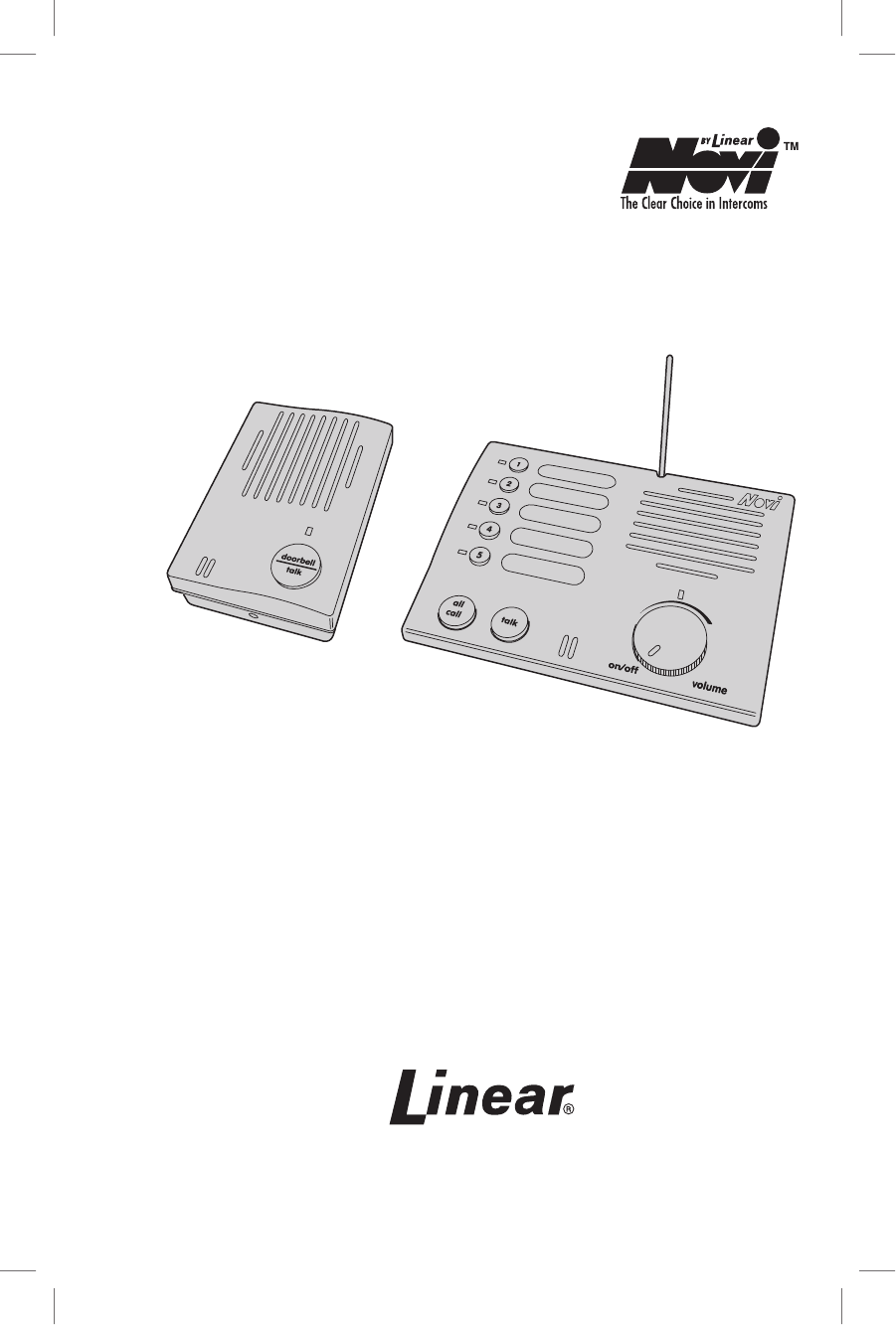
CONSOLE DESCRIPTION
Novi’s 5-channel Wireless Intercom Consoles provide a wireless
audio communication link between up to ve Console stations and
one or two remote Wireless Doorbell Intercom units.
The intercom uses digital signals to control the stations called and
provide a unique “security code” that prevents other nearby Novi
5-channel intercoms from accessing the system. Either of two radio
frequencies can be selected for the intercoms to further eliminate
the chance of interference from adjacent systems.
The Console features ve station number pushbuttons for selecting
the party to call. The ALL CALL button can be used to call all ve
stations. Pressing the TALK button calls the selected station(s),
then controls the direction of the conversation. Each intercom user
presses their TALK button to activate the microphone during the
conversation.
The Doorbell works with Console stations 4 or 5. Pressing the
Doorbell’s TALK button sounds a “ding-dong” (station 5), or “dong”
(station 4) at the Console, then the conversation begins by pressing
the units’ talk buttons.
For privacy, a MUTE switch on each Console can be set to prevent
Wireless Doorbell tones and ALL CALL messages from sounding
through that Console’s speaker.
The Console can be placed on a table or shelf, or mounted to a wall
with the screws provided. The small, antenna adjusts for Console
table or wall mounting. Power for the Console is provided by a
small plug-in transformer.
The Doorbell attaches to a wall with the mounting plate provided.
Two 9-volt alkaline batteries power the Doorbell intercom.
TABLE OF CONTENTS
CONSOLE DESCRIPTION.......................................................................................... a
CONSOLE FEATURES ...............................................................................................b
DOORBELL FEATURES .............................................................................................1
CONSOLE ANTENNA...............................................................................................2
PROGRAMMING THE STATIONS ............................................................................3-4
WALL MOUNTING THE DOORBELL...........................................................................5
WALL MOUNTING THE CONSOLE ............................................................................6
OPERATING THE DOORBELL & CONSOLE .................................................................7
OPERATING MULTIPLE CONSOLES.........................................................................8-9
TROUBLESHOOTING .............................................................................................10
CHANGING SYSTEM SETTINGS ..............................................................................11
LINEAR LIMITED WARRANTY .................................................................................12
214601 X1 - IMAGE 2 214601 X1 - IMAGE 3
1
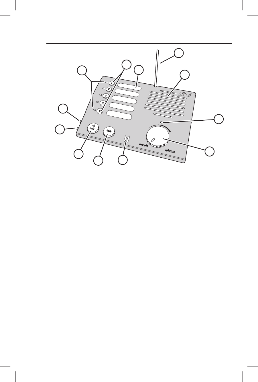
CONSOLE FEATURES
1. STATION INDICATORS
Indicators light when a station number button is pressed to show the station(s) that will be called. Indicators
blink to show a call in progress. Indicators ash during conversation to show the busy stations.
2. STATION BUTTONS
Press a button to select the intercom station(s) to be called. Pressing again de-selects the station.
3. STATION LABEL AREAS
For applying labels that identify the intercom station locations.
4. ANTENNA
Receives and sends the wireless intercom signals. Antenna pivots for Console horizontal and vertical
mounting.
5. SPEAKER
Sounds audio from the calling station. Volume is adjustable with the volume control.
6. POWER INDICATOR
Lights to show that Console power is switched on.
7. VOLUME CONTROL - POWER SWITCH
Switches Console power ON & OFF. Adjusts the volume of the Console’s speaker.
8. MICROPHONE
High-gain microphone monitors audio from the calling station while the Console’s TALK button is
pressed.
9. TALK BUTTON
Press and release to call selected station(s). During conversation, press and hold when talking.
10. ALL CALL BUTTON
Press to select all stations for calling. Press again to de-select all stations.
11. MUTE SWITCH
When ON, the Console will not sound Doorbell Intercom chime tones or respond to All Call signals.
12. FREQUENCY SWITCH
Selects frequency A or B. All intercoms used in the same system must be set to the same frequency.
3
1
2
4
5
6
7
8
9
10
11
12
214601 X1 - IMAGE 2 214601 X1 - IMAGE 3
2
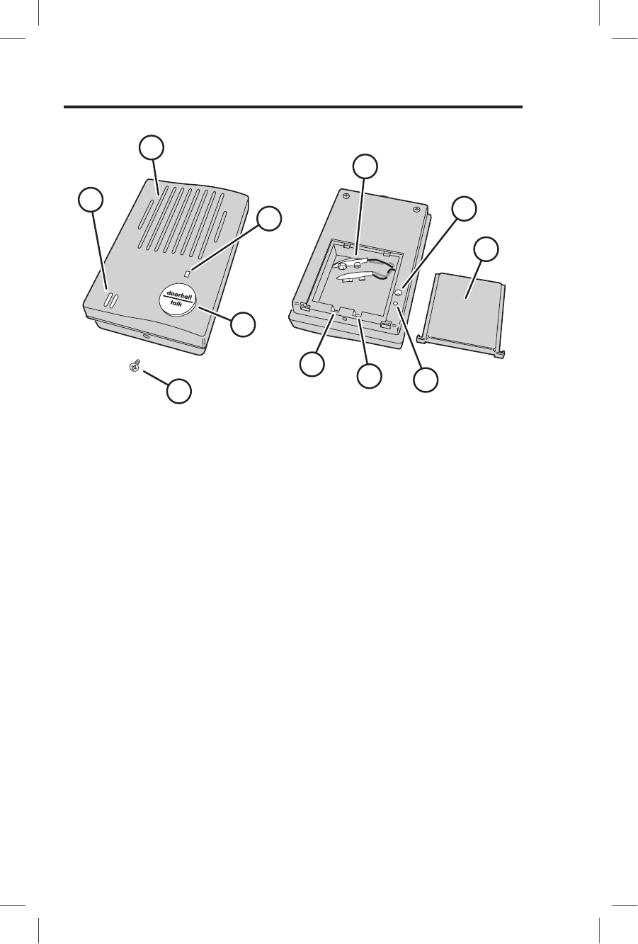
DOORBELL FEATURES
1. MICROPHONE
High-gain microphone monitors audio while the Doorbell’s TALK button is pressed.
2. SPEAKER
Sounds audio from the intercom Console. Volume is adjustable with the volume control (see Item #6).
3. POWER INDICATOR
Lights to show that Doorbell power is on. Doorbell power automatically switches ON when TALK button is
pressed. The power automatically switches OFF 15 seconds after the last intercom communication.
4. DOORBELL-TALK BUTTON
Press to turn ON the Doorbell power and sound the chime at all of the intercom Consoles (Consoles with
their MUTE switch ON will not sound the Doorbell chime). During intercom conversation, press and hold
the DOORBELL-TALK button while speaking.
5. BATTERY CLIPS
For connection to two 9-volt alkaline batteries.
6. VOLUME CONTROL
Sets the volume level of the Doorbell’s speaker.
7. BATTERY DOOR
Slides off rear case to expose the battery compartment, CHANNEL switch, and FREQUENCY switch.
8. PROGRAM BUTTON
Press until two beeps sound to cause the Doorbell to enter program mode.
9. FREQUENCY SWITCH
Sets the Doorbell to frequency “A” or “B”. All intercoms used in the same system must be set to the same
frequency.
10. STATION SWITCH
Sets the Doorbell to station 4 or 5. When set for station 5, the Doorbell will sound a “ding-dong” chime at
the Console. When set for station 4, the Doorbell will sound a “dong” chime at the Console.
11. CASE LOCKING SCREW
Secures the Doorbell to the mounting plate.
1
2
3
4
5
6
7
8
9
10
11
214601 X1 - IMAGE 4 214601 X1 - IMAGE 5
3
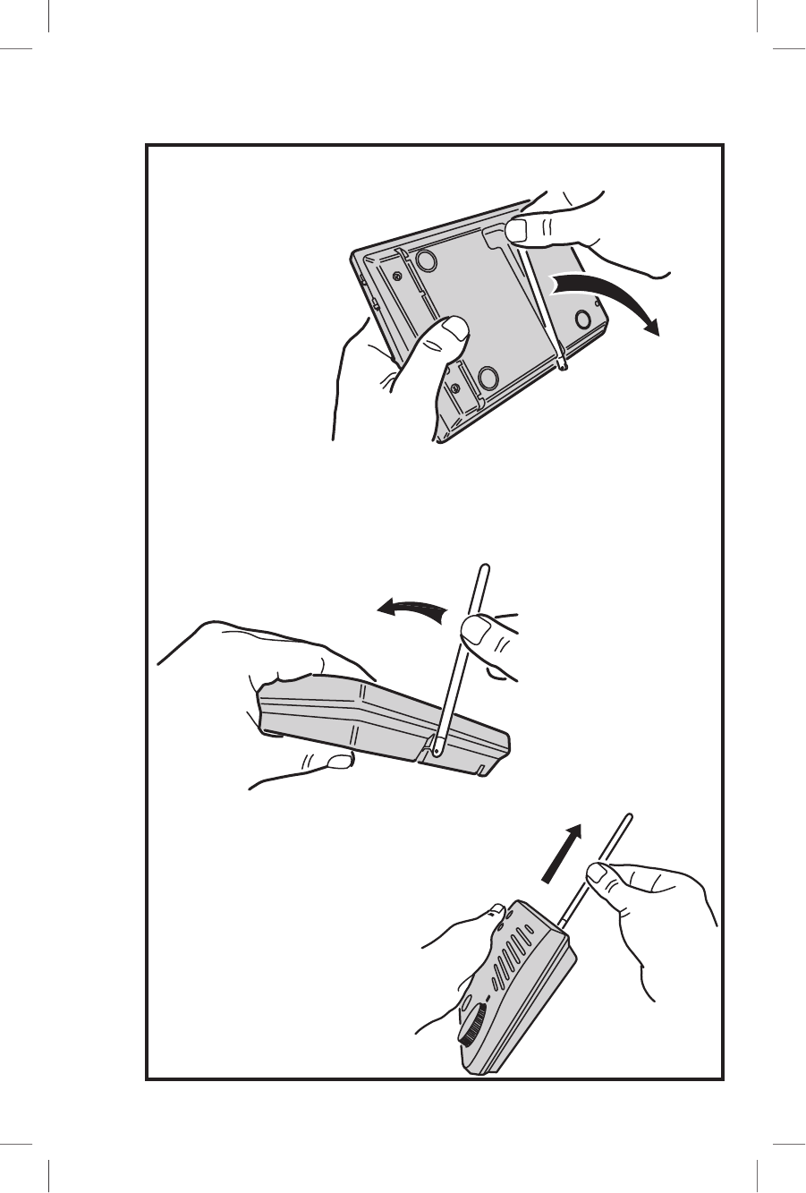
FOR TABLE OR SHELF MOUNTING...
FOR WALL MOUNTING...
SWING ANTENNA
OUT FROM BOTTOM
OF CASE
SWING ANTENNA
ALL THE WAY UP
POINT ANTENNA
STRAIGHT UP
FROM CASE
CONSOLE ANTENNA
214601 X1 - IMAGE 4 214601 X1 - IMAGE 5
4
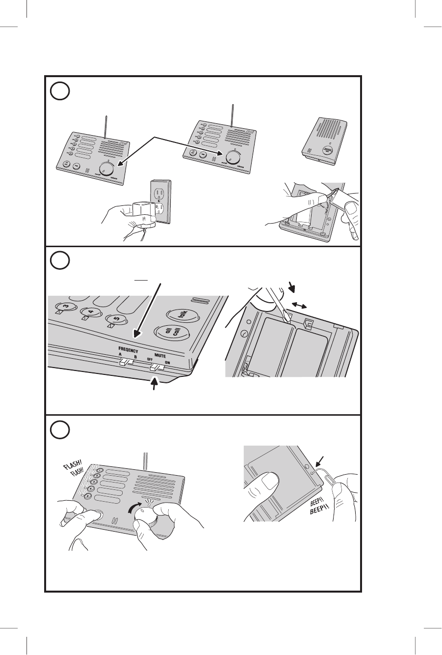
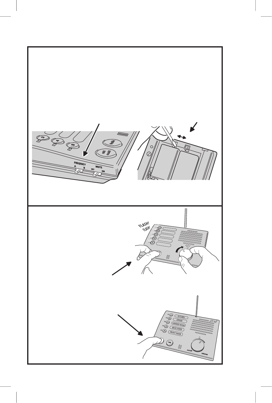
PROGRAMMING THE STATIONS
3
1
2
BRING ALL UNITS TOGETHER THAT
ARE GOING TO BE USED IN THE SYSTEM
PLUG IN
CONSOLE(S)
TRANSFORMER
TURN CONSOLE(S)
POWER KNOB OFF
CONNECT
DOORBELL(S)
BATTERIES
SET ALL FREQUENCY SWITCHES THE SAME (A OR B)
SET ALL CONSOLE MUTE
SWITCHES TO OFF
CONSOLE
DOORBELL
SET ALL UNITS INTO PROGRAM MODE
ON CONSOLE(S), PRESS & HOLD DOWN ALL CALL & TALK
BUTTONS; THEN TURN POWER ON WITH THE VOLUME KNOB.
WHEN ALL STATION LIGHTS FLASH, RELEASE BUTTONS.
ON DOORBELL(S), USE AN OBJECT TO
PRESS AND HOLD THE PROGRAM BUTTON
UNTIL TWO BEEPS SOUND; THEN RELEASE
THE PROGRAM BUTTON
PROGRAM
BUTTON
INSIDE HOLE
CONSOLE
CONSOLE CONSOLE
DOORBELL
DOORBELL
SET SWITCHES
SET
FREQUENCY
B
A
NOTE: FOR BEST PERFORMANCE
KEEP UNITS AT LEAST 6 FEET APART
FROM EACH OTHER
214601 X1 - IMAGE 6 214601 X1 - IMAGE 7
5
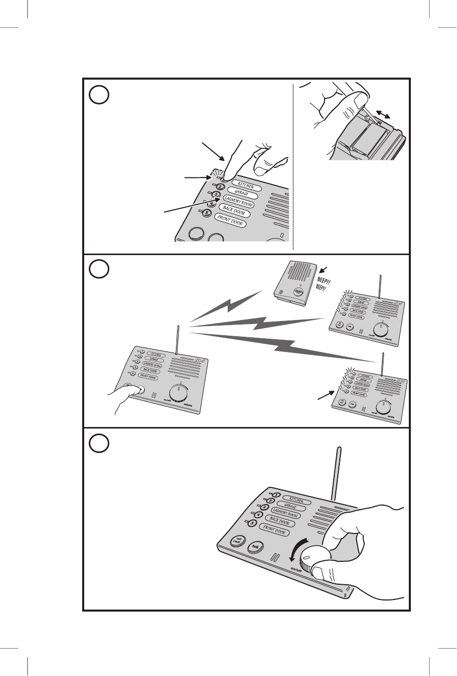
PROGRAMMING THE STATIONS
DOORBELL
CONSOLE
CONSOLE
6
4
5
ON EACH CONSOLE, PRESS
A STATION NUMBER BUTTON
TO SET THAT CONSOLE'S
STATION NUMBER (SELECT
A DIFFERENT NUMBER FOR
EACH CONSOLE)
THE STATION NUMBER
INDICATOR WILL
STAY LIT
APPLY LABELS TO
DESCRIBE THE
LOCATIONS
CONSOLE
DOORBELL
SET STATION NUMBERS
DOORBELLS CAN BE SET
FOR STATION 4 OR 5
SET STATION SWITCH
TO 5 FOR "DING-DONG",
OR TO 4 FOR "DONG" CHIME
WHEN DOORBELL BUTTON
IS PRESSED (TO TELL
FRONT FROM BACK DOOR)
SET
STATION
5
4
CONSOLE
PRESS THE TALK BUTTON
ON ANY CONSOLE TO SEND
THE "SECURITY CODE" TO ALL
OTHER UNITS
SEND SYSTEM CODE
DOORBELL BEEPS 10 TIMES
THEN TURNS ITS POWER OFF
EACH UNIT SIGNALS WHEN
THE "SECURITY CODE"
IS RECEIVED
ALL CONSOLE STATION
INDICATORS LIGHT FOR
2 SECONDS
TURN CONSOLE(S) OFF
TO COMPLETE PROGRAMMING,
TURN POWER OFF ON ALL
CONSOLES
NOTE: FOR THE CONSOLE
TO EXIT THE PROGRAM MODE,
THE POWER MUST BE
SWITCHED OFF
TURN VOLUME KNOB
COUNTERCLOCKWISE
UNTIL POWER IS OFF
214601 X1 - IMAGE 6 214601 X1 - IMAGE 7
6
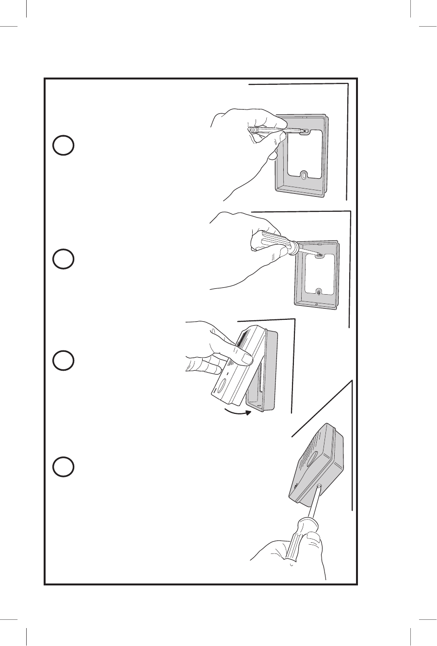
WALL MOUNTING THE DOORBELL
3
1
2
4
USE MOUNTING
PLATE AND PENCIL
TO MARK SCREW
LOCATIONS
ATTACH MOUNTING
PLATE USING THE
SCREWS PROVIDED
TILT DOORBELL
INTO MOUNTING
PLATE
SECURE DOORBELL TO
MOUNTING PLATE WITH
THE CASE LOCKING SCREW
NOTE: WAIT UNTIL AFTER
ADJUSTING THE DOORBELL
AUDIO VOLUME BEFORE
FULLY TIGHTENING THE
LOCKING SCREW
NOTE: DO NOT MOUNT THE DOORBELL
UNIT WHERE IT WILL BE EXPOSED
TO EXCESSIVE MOISTURE, DUST,
OR IN DIRECT SUNLIGHT
214601 X1 - IMAGE 8 214601 X1 - IMAGE 9
7
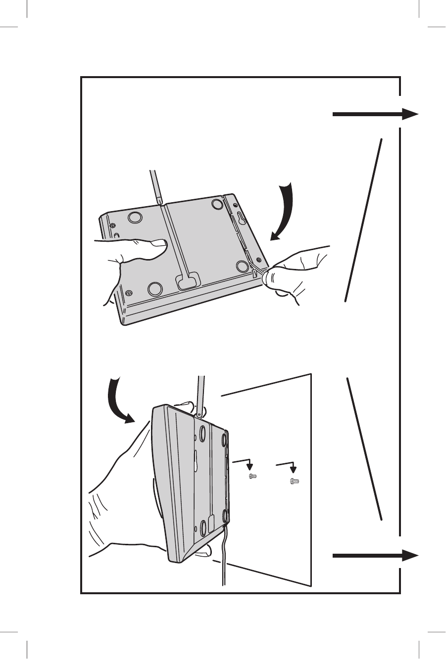
WALL MOUNTING THE CONSOLE
ROUTE TRANSFORMER
WIRE INTO WIRING SLOT
MOUNT CONSOLE
ON WALL SCREWS
MARK SCREW
LOCATIONS AND
DRIVE IN SCREWS
LEAVING HEADS
ABOUT 1/4" OUT
NOTE: DO NOT MOUNT THE CONSOLE
OUTDOORS, OR WHERE IT WILL BE
EXPOSED TO EXCESSIVE MOISTURE,
DUST, OR IN DIRECT SUNLIGHT
LEFT SCREW
RIGHT SCREW
214601 X1 - IMAGE 8 214601 X1 - IMAGE 9
8
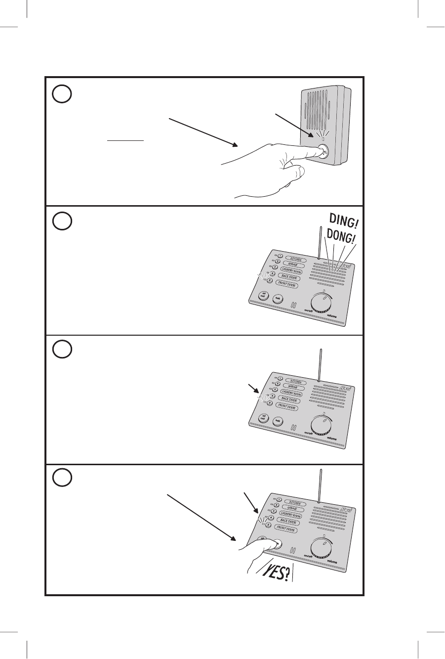
OPERATING THE DOORBELL & CONSOLE
3
1
2
4
THE VISITOR PRESSES THE
DOORBELL-TALK BUTTON
NOTE: THE CONSOLE
POWER MUST BE ON, AND
THE VOLUME MUST BE
SET ABOVE MINIMUM
THE VISITOR MAKES THE CALL
CONSOLE ANNOUNCES THE VISITOR
SEE THE VISITOR'S LOCATION
CONSOLE
HAVE THE CONVERSATION
RESPOND TO THE VISITOR
BY PRESSING & HOLDING
THE TALK BUTTON WHILE
SPEAKING, RELEASE THE
TALK BUTTON AFTER SPEAKING
THE CONVERSATION GOES BACK AND
FORTH, WITH EACH PERSON PRESSING
THEIR OWN TALK BUTTON
NOTE: DOORBELLS WILL GO ON STANDBY
AFTER 15 SECONDS OF NO TALKING
STATION INDICATOR STAYS
LIT WHILE TALKING & BLINKS
WHEN LISTENING
THE CONSOLE WILL INDICATE
THE DOORBELL STATION THAT
CALLED
NOTE: A CONSOLE MUST
RESPOND WITHIN 15 SECONDS,
OR THE DOORBELL UNIT WILL
AUTOMATICALLY SHUT OFF
CONSOLE
EACH CONSOLE WILL CHIME
A "DING-DONG" (FOR STATION 5)
OR A "DONG" (FOR STATION 4)
NOTE: IF A CONSOLE'S MUTE
SWITCH IS "ON", THE DOORBELL
CHIME WILL NOT SOUND
GREEN POWER
INDICATOR LIGHTS
WHILE DOORBELL
POWER IS ON
DOORBELL
CONSOLE
STATION INDICATOR
BLINKS TO SHOW WHICH
STATION CALLED
214601 X1 - IMAGE 10 214601 X1 - IMAGE 11
9
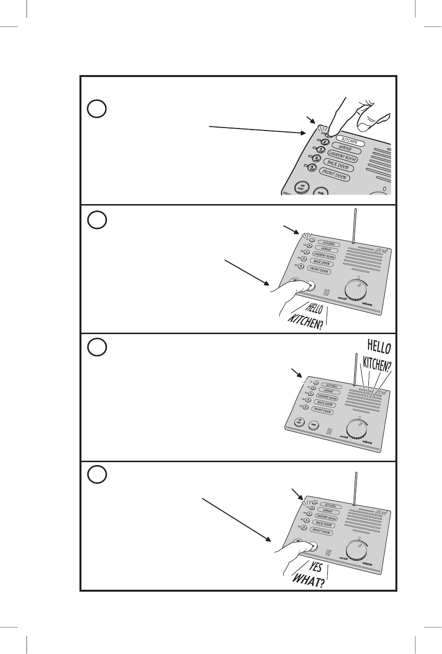
OPERATING MULTIPLE CONSOLES
3
1
2
4
SELECTIVE STATION CALL
WITH CONSOLE POWER ON,
PRESS THE BUTTON FOR THE
CONSOLE THAT YOU WANT TO CALL
(DOORBELLS CAN NOT BE CALLED)
NOTE: MORE THAN ONE
STATION CAN BE CHOSEN,
BUT ONLY ONE STATION CAN
RESPOND AT A TIME
CHOOSE WHOM TO CALL
MAKE THE CALL
PRESS AND HOLD THE TALK BUTTON,
SPEAK TOWARDS THE CONSOLE
RELEASE THE TALK BUTTON
WHEN YOU ARE FINISHED TALKING
WAIT FOR RESPONSE
EXAMPLE: GARAGE IS CALLING KITCHEN
KITCHEN CONSOLE
STATION INDICATOR
LIGHTS TO SHOW WHICH
STATION CALLED
HAVE THE CONVERSATION
RESPOND TO THE CALLER
BY PRESSING & HOLDING
THE TALK BUTTON WHILE
SPEAKING, RELEASE THE
TALK BUTTON AFTER SPEAKING
THE CONVERSATION GOES BACK AND
FORTH, WITH EACH PERSON PRESSING
THEIR OWN TALK BUTTON
NOTE: CONSOLES WILL GO ON STANDBY
AFTER 20 SECONDS OF NO TALKING
STATION INDICATOR STAYS
LIT WHILE TALKING & BLINKS
WHEN LISTENING
STATION
INDICATOR
LIGHTS
GARAGE CONSOLE
STATION
INDICATOR
STAYS LIT
THE CONSOLE CALLED
WILL SOUND THE MESSAGE
THE CALLER THEN WAITS
FOR THE PERSON TO RESPOND
NOTE: THE CONSOLE CALLED HAS
20 SECONDS TO RESPOND, OR THE
CALL WILL BE CANCELED
GARAGE CONSOLE
KITCHEN CONSOLE
214601 X1 - IMAGE 10 214601 X1 - IMAGE 11
10
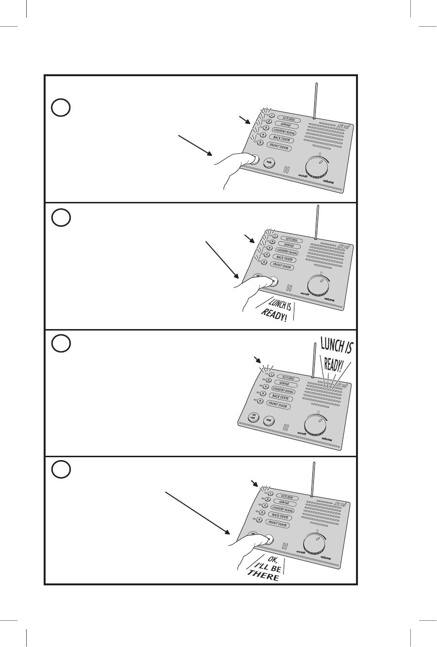
OPERATING MULTIPLE CONSOLES
3
1
2
4
STATION ALL-CALL
WITH CONSOLE POWER ON,
PRESS THE ALL CALL BUTTON
CHOOSE STATION ALL-CALL
MAKE THE CALL
PRESS AND HOLD THE TALK BUTTON,
SPEAK TOWARDS THE CONSOLE
RELEASE THE TALK BUTTON
WHEN YOU ARE FINISHED TALKING
NOTE: DOORBELL UNITS, AND ANY
CONSOLE WITH ITS MUTE SWITCH ON,
WILL NOT RECEIVE THE ALL-CALL MESSAGE
WAIT FOR RESPONSE
EXAMPLE: KITCHEN IS CALLING EVERYONE
ALL CONSOLES THAT RECEIVED THE
ALL-CALL MESSAGE WILL SOUND THE
MESSAGE
THE CALLER THEN WAITS
FOR A PERSON TO RESPOND
NOTE: THE CONSOLES CALLED HAVE
20 SECONDS TO RESPOND, OR THE
CALL WILL BE CANCELED
STATION INDICATOR
LIGHTS TO SHOW WHICH
STATION CALLED
HAVE THE CONVERSATION
ALL STATION
INDICATORS
LIGHT
ALL STATION
INDICATORS
STAY LIT
RESPOND TO THE CALLER
BY PRESSING & HOLDING
THE TALK BUTTON WHILE
SPEAKING, RELEASE THE
TALK BUTTON AFTER SPEAKING
THE CONVERSATION GOES BACK AND
FORTH, WITH EACH PERSON PRESSING
THEIR OWN TALK BUTTON
CONSOLES WILL GO ON STANDBY
AFTER 20 SECONDS OF NO TALKING
STATION INDICATOR STAYS
LIT WHILE TALKING & BLINKS
WHEN LISTENING
KITCHEN CONSOLE
KITCHEN CONSOLE
GARAGE CONSOLE
GARAGE CONSOLE
214601 X1 - IMAGE 12 214601 X1 - IMAGE 13
11
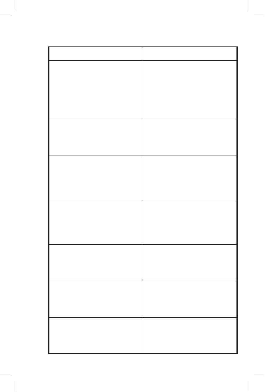
TROUBLESHOOTING
MOTPMYS MOTPMYS MOTPMYS MOTPMYS MOTPMYS YDEMER YDEMER YDEMER YDEMER YDEMER
TONLLIWROTACIDNIREWOP
THGIL
ELOSNOCEHTERUSEB
DEGGULPSIREMROFSNART
DEHCTIWS-NUNAOTNI
TELTUO
TINULLEBROODEHTERUSEB
ENILAKLATLOV-9HSERFSAH
SEIRETTAB
EHTMORFMUHEVISSECXE
REKAEPS
DROCREWOPELOSNOCPEEK
ANNETNAMORFYAWA
SITIFITINULLEBROODEVOM
ENILCANARAEN
TAKROWOTSLIAFMETSYS
ECNATSID
ELOSNOCEHTERUSEB
PUDETNIOPSIANNETNA
OTDNUORASTINUEVOM
RETTEBENIMRETED
SNOITACOLNOITPECER
ECIOVSEVIECERMETSYS
DETALER-NONMORFSLANGIS
TNEMPIUQE
YCNEUQERFEHTEGNAHC
TINUHCAENOSEHCTIWS
EDOCYTIRUCESEHTEGNAHC
)EGAPTXENEES(
SEVIECERMETSYS
ESIONLACIRTCELE
MORFYAWASTINUEVOM
CIRTCELE,SRETUPMOC
REMMIDTHGIL,SROTOM
.CTE,SEHCTIWS
NOITCNUFOTSLIAFMETSYS
METSYSEHTMROFREP
NIAGAGNIMMARGORP
MORFYAWASTINUEVOM
STCEJBOLATEM
SNOITCNUFMETSYS
YLLACITARE
TASIEREHTTAHTERUSEB
GNICAPSTEEF6TSAEL
STINUNEEWTEB
214601 X1 - IMAGE 12 214601 X1 - IMAGE 13
12
CHANGING SYSTEM SETTINGS
CHANGING THE SYSTEM'S CODE
CHANGING THE SYSTEM'S FREQUENCY
ON A CONSOLE:
1. START WITH THE POWER OFF
2. PRESS & HOLD DOWN ALL CALL & TALK BUTTONS
3. TURN POWER ON WITH THE VOLUME KNOB
4. WHEN ALL STATION LIGHTS FLASH, RELEASE BUTTONS.
IF, AFTER CHANGING FREQUENCY,
ANOTHER INTERCOM SYSTEM
IS STILL COMMUNICATING WITH YOUR
SYSTEM, TRY CHANGING YOUR
SYSTEM'S SECURITY CODE
CONSOLE
DOORBELL
B
A
NOTE: ALL FREQUENCY
SWITCHES MUST MATCH
THEN:
PRESS THE ALL CALL BUTTON, THIS WILL
CHANGE THE CONSOLE'S SECURITY CODE
THEN:
REFER TO THE "PROGRAMMING THE STATIONS"
SECTION IN THIS MANUAL AND PERFORM
STEPS #3, #5, & #6
THIS WILL PROGRAM THE NEW "SECURITY CODE"
INTO ALL OF THE OTHER UNITS
IF ANOTHER INTERCOM SYSTEM
IS COMMUNICATING WITH YOUR
SYSTEM, TRY CHANGING YOUR
SYSTEM'S FREQUENCY
CHANGE THE FREQUENCY
SWITCH ON EACH CONSOLE
CHANGE THE FREQUENCY
SWITCH ON EACH DOORBELL
214601 X1 - IMAGE 14 214601 X1 - IMAGE 15

13
LINEAR LIMITED WARRANTY
Linear Corporation (the Company) warrants to the original purchaser that products
delivered hereunder will be free of defects in materials and workmanship for a
period of twelve (12) months from the date of purchase.
The Company within said period shall, at its option, either repair or replace free of
charge, any product or part thereof found (except batteries), upon the Company’s
inspection, to be so defective, and will return the repaired or replaced product to
the purchaser at Company’s expense.
For warranty service and shipping instructions contact WEMA at the telephone
number shown below. Devices must be sent at owner’s expense and be accompanied
with statement of defect and proof of purchase.
This warranty is conditioned on the following:
1). The Company must be notied within one year of purchase and have
been given the opportunity of inspection by return of any alleged defective
product free and clear of all liens and encumbrances to the Company or its
distributor; and
2). The product must not have been abused, misused or improperly maintained
and/or repaired during such period; and
3). Such defect has not been caused by corrosion or exposure to other than
ordinary wear and tear.
THE COMPANY MAKES NO OTHER WARRANTY OR REPRESENTATION OF ANY KIND
WHATSOEVER INCLUDING ANY WARRANTY OF MERCHANTABILITY OR FITNESS FOR A
PARTICULAR PURPOSE.
The Company’s maximum liability hereunder is limited to the purchased price of the
product. In no event shall the Company be liable for any consequential, indirect,
incidental or special damages of any nature arising from the sale or use of the
product, whether based in contract, tort, strict liability or otherwise.
Note: Some states do not allow limitations on incidental or consequential damages
or how long an implied warranty lasts, so that the above limitations may not fully
apply. This warranty gives specic legal rights and you may also have other rights
which may vary from state to state.
For Warranty Service Call: WEMA 1-800-528-4454
IMPORTANT !!!
Linear radio controls provide a reliable communications link and ll an important
need in portable wireless signaling. However, there are some limitations which must
be observed.
• For U.S. installations only: The radios are required to comply with FCC Rules and
Regulations as Part 15 devices. As such, they have limited transmitter power
and therefore limited range.
• A receiver cannot respond to more than one transmitted signal at a time
and may be blocked by radio signals that occur on or near their operating
frequencies, regardless of code settings.
• Changes or modications to the device may void FCC compliance.
• Infrequently used radio links should be tested regularly to protect against
undetected interference or fault.
• A general knowledge of radio and its vagaries should be gained prior to acting
as a wholesale distributor or dealer, and these facts should be communicated
to the ultimate users.
• This device complies with FCC Part 15 and Industry Canada Rules and
Regulations. Operation is subject to the following two conditions: (1) This
device may not cause harmful interference, and (2) this device must accept
any interference received, including interference that may cause undesired
operation.
214601 X1 - IMAGE 14 214601 X1 - IMAGE 15

Copyright © 2001 Linear Corporation 214601 X1
214601 X1 - IMAGE 16