Nortek Security and Control SST00127 Security/Remote Control Transmitter User Manual 232812A indd
Nortek Security & Control LLC Security/Remote Control Transmitter 232812A indd
user manual
DXS-36AF
SUPERVISED
DOOR/WINDOW
TRANSMITTER
Installation Instructions
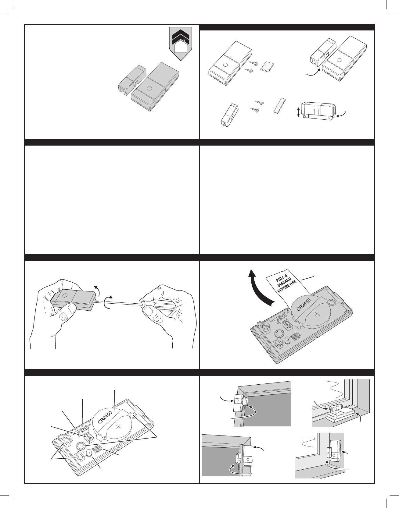
DXS-31AF FEATURES & ACCESSORIES
PRINTER’S INSTRUCTIONS:
INSTR,INSTL,DXS-36AF - LINEAR P/N: 232812 X4 - INK: BLACK - MATERIAL: 20 LB. MEAD BOND - SIZE: 8.500” X 11.000” - SCALE: 1-1 - SIDE 1 OF 2
PRODUCT DESCRIPTION
The DXS-36AF is a battery powered stationary transmitter designed for use with AlarmForce
receivers. Triggering the transmitter with its built-in magnetic switch or an external switch
sends a digitally coded wireless signal to its companion receiver. The DXS-36AF can send fi ve
different signals: alarm, restore, low battery, status, and tamper.
The digital code format used in the transmitter features over a million possible codes. The
transmitter is pre-coded at the factory to a unique system code, so no fi eld coding is required.
The receiver must be programmed to the transmitter’s system code before testing and
operation. Refer to the receiver’s instructions for details on programming.
In a typical installation, the magnet is mounted on a door or window and the transmitter is
mounted on the frame. When the magnet moves more than 1/2” away from the transmitter, an
alarm signal is sent. When the magnet returns next to the unit, a restore signal is sent. The
magnet is adjustable with four height positions. A 1/4” high magnet spacer is also supplied to
snap on to the base of the magnet.
Alarms and restores can also be sent from external normally closed contacts wired to the
transmitter’s external switch input terminals. The two screw terminals are for connection to one
normally closed external contact or multiple normally closed external contacts wired in series.
External contacts wire through an opening in the rear of the case.
An internal jumper selects which switch input to use. Selections are: internal magnetic switch
only, external switch only, or both external and internal switch.
Approximately every two hours, the DXS-36AF will send a status signal to the receiver. The
status signal updates the receiver to the transmitter’s current condition. By monitoring status
signals, the receiver can determine if a transmitter has a low battery or has been removed
from the system.
Pressing the test button on the case sends a test signal that updates the receiver with the
current state of the transmitter. When the test button is pressed, the transmit indicator lights.
For two minutes after the test button is pressed, the indicator will light each time the unit sends
a signal. The indicator light shines through the transmitter case.
The transmitter contains a feature to detect unauthorized tampering. When the transmitter’s
case is opened, a tamper signal is sent to the receiver.
The transmitter is powered from one Type 2450 3-Volt lithium battery with an expected battery
life of up to 5 years.
OPENING CASE REMOVE BATTERY PROTECTION STRIP
COMPONENT LOCATIONS EXAMPLE INSTALLATIONS
ALARMFORCE
AlarmForce Industries Inc.
675 Garyray Drive
Toronto, ON M9L 1R2, Canada
TRANSMITTER
MOUNTED ON
DOOR JAMB
MAGNET
MOUNTED
ON DOOR
MAGNET MOUNTED
ON DOOR
TRANSMITTER
MOUNTED ON
WINDOW SILL
MAGNET MOUNTED
ON WINDOW FRAME
SLIDING WINDOW
LEFT OPENING DOOR
RIGHT OPENING DOOR
TRANSMITTER
MOUNTED ON
DOOR JAMB
TRANSMITTER
MOUNTED ON
WINDOW FRAME
MAGNET
MOUNTED
ON WINDOW
SASH STILE
DOUBLE-HUNG
WINDOW
TYPE 2450
BATTERY
INPUT
SELECT
JUMPER
TEST
BUTTON
EXTERNAL
SWITCH
INPUT SIGNAL
INDICATOR
NOTE: SIGNAL INDICATOR
IS ENABLED FOR TWO
MINUTES AFTER PRESSING
THE TEST BUTTON
TAMPER
DETECTOR
MOUNTING
SCREW
HOLES
INTERNAL
MAGNETIC
SWITCH
NOTE: BE SURE TO KEEP
TAMPER DETECTOR AREA
CLEAR OF ANY WIRES
PULL BATTERY
STRIP TO REMOVE
BATTERY
PROTECTION STRIP
TWIST
LIFT
OPEN THE CASE TOP BY TWISTING A
SMALL FLAT BLADE SCREWDRIVER OR
COIN IN THE SLOT ON EITHER END OF THE
TRANSMITTER
DXS-36AF
TRANSMITTER
TRANSMITTER
SCREWS AND
DOUBLE STICK TAPE
MAGNET
SCREWS AND
DOUBLE STICK TAPE
ADJUSTABLE
MAGNET
MAGNET CAN BE MOUNTED UP TO
1/2" FROM LEFT SIDE OF
TRANSMITTER
1/2" GAP DISTANCE
MAXIMUM
SQUEEZE MAGNET TABS TO
ADJUST MAGNET HEIGHT (4 POSITIONS)
MAGNET
ADJUSTMENT
TAB (EACH SIDE)
TRANSMITTER MOUNTING ADJUSTING MAGNET HEIGHT
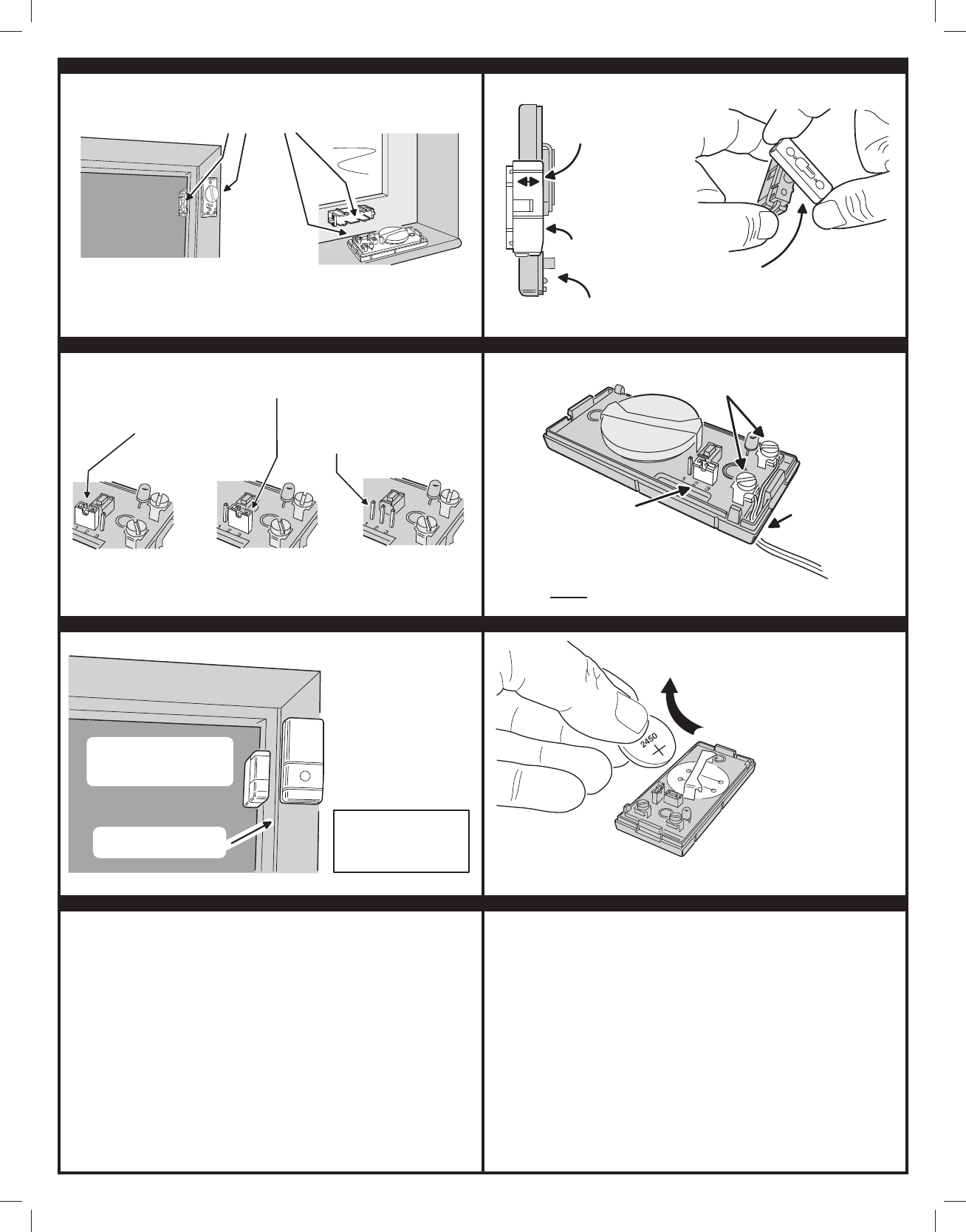
OPTION JUMPER POSITIONS CONNECTING EXTERNAL CONTACTS
PROGRAMMING RECEIVER CHANGING THE BATTERY
• The radios are required to comply with IC Rules and Regulations. As such, they have limited transmitter power and therefore
limited range.
• A receiver cannot respond to more than one transmitted signal at a time and may be blocked by radio signals that occur on
or near their operating frequencies, regardless of code settings.
• Infrequently used radio links should be tested regularly to protect against undetected interference or fault.
• A general knowledge of radio and its vagaries should be gained prior to acting as a wholesale distributor or dealer, and these
facts should be communicated to the ultimate users.
This device complies with Industry Canada licence-exempt RSS standard(s). Operation is subject to the following two
conditions: (1) this device may not cause interference, and (2) this device must accept any interference, including interference
that may cause undesired operation of the device.
Le présent appareil est conforme aux CNR d’Industrie Canada applicables aux appareils radio exempts de licence.
L’exploitation est autorisée aux deux conditions suivantes : (1) l’appareil ne doit pas produire de brouillage, et (2) l’utilisateur
de l’appareil doit accepter tout brouillage radioélectrique subi, même si le brouillage est susceptible d’en compromettre le
fonctionnement.
This device complies with Part 15 of the FCC Rules. Operation is subject to the following two conditions: (1) This device may
not cause harmful interference, and (2) This device must accept any interference received, including interference that may
cause undesired operation.
This equipment has been tested and found to comply with the limits for Class B Digital Device, pursuant to Part 15 of the FCC
Rules. These limits are designed to provide reasonable protection against harmful interference in a residential installation.
This equipment generates and can radiate radio frequency energy and, if not installed and used in accordance with the
instructions, may cause harmful interference to radio communications. However, there is no guarantee that interference will
not occur in a particular installation. If this equipment does cause harmful interference to radio or television reception, which
can be determined by turning the equipment off and on, the user is encouraged to try to correct the interference by one or
more of the following measures.
• Reorient or relocate the receiving antenna
• Increase the separation between the equipment and receiver
• Connect the equipment into an outlet on a circuit different from that to which the receiver is connected
• Consult the dealer or an experienced radio/TV technician for help
Any changes or modifi cations not expressly approved by the party responsible for compliance could void the user’s authority
to operate the equipment.
This device conforms to Industry Canada’s rules. Any changes to the equipment, not expressly approved by Linear LLC, could
void the user’s authority to operate the equipment.
Cet appareil est conforme aux règlements de l’Industrie Canada. Tout changement à l’équipement, sans le consentement
exprès de Linear LLC, peut résulter à l’annulation de l’autorité confi ée à l’usager d’opérer cet équipement.
WHEN THE SYSTEM INDICATES A
LOW BATTERY FOR THE TRANSMITTER,
REMOVE THE OLD BATTERY AND REPLACE
IT WITH A FRESH TYPE 2450 3-VOLT
COIN CELL BATTERY
BE SURE TO INSTALL THE BATTERY
WITH THE PLUS SIDE UP !!!
TEST THE SYSTEM AFTER
CHANGING THE BATTERY
WIRE EXTERNAL NORMALLY CLOSED
CONTACTS TO THE SCREW TERMINALS
PLACE JUMPER ON PINS 2 & 3
FOR EXTERNAL CONTACT ONLY
REMOVE THE JUMPER TO USE BOTH
INTERNAL AND EXTERNAL CONTACTS
NOTE: THE INTERNAL AND EXTERNAL
CONTACTS ARE IN SERIES. BOTH NEED
TO BE CLOSED TO RESTORE THE TRANSMITTER
REMOVE SEALING PLUG
AND ROUTE WIRES
THROUGH SLOT IN
BOTTOM OF CASE
WIRE MULTIPLE EXTERNAL
CONTACTS IN SERIES
JUMPER ON 1 & 2 SELECTS
INTERNAL MAGNETIC SWITCH
INTERNAL EXTERNAL BOTH
JUMPER ON 2 & 3 SELECTS
EXTERNAL SWITCH TERMINALS
NO JUMPER SELECTS BOTH THE
INTERNAL MAGNETIC SWITCH AND
THE EXTERNAL SWITCH TERMINALS
1. PLACE RECEIVER INTO
PROGRAM OR "LEARN" MODE
2. PRESS THE TRANSMITTER'S
TEST BUTTON
3. ACTIVATE TRANSMITTER BY
OPENING DOOR OR WINDOW
4. VERIFY THAT THE RECEIVER
ACCEPTED THE SIGNAL
5. REPLACE TRANSMITTER COVER
WHEN FINISHED
OPEN DOOR, THE TRANSMIT
INDICATOR SHOULD LIGHT
NOTE: THE TRANSMIT INDICATOR
WILL ONLY LIGHT DURING
TRANSMISSIONS FOR TWO
MINUTES AFTER PRESSING THE
TEST BUTTON
NOTE: THE CASE MUST BE CLOSED
TO LEARN INTO THE RECEIVER
(IT WON'T LEARN IN IF TRANSMITTER
IS IN TAMPER MODE)
ADJUST MAGNET
HEIGHT UNTIL
CASE LEVELS
ARE ABOUT EQUAL
TRANSMITTER
CASE BOTTOM
MAGNET
THE SNAP-ON MAGNET SPACER
CAN BE USED TO ADD 1/4" HEIGHT
TO THE MAGNET (SPACERS CAN ALSO
BE SNAPPED TOGETHER FOR MORE LIFT)
ATTACH TRANSMITTER AND MAGNET
USING THE SCREWS OR THE
DOUBLE-STICK TAPE PROVIDED
NOTE: ATTACHING THE TRANSMITTER WITH DOUBLE-STICK
TAPE IS NOT ALLOWED IN UL INSTALLATIONS
PRINTER’S INSTRUCTIONS:
INSTR,INSTL,DXS-36AF - LINEAR P/N: 232812 X4 - INK: BLACK - MATERIAL: 20 LB. MEAD BOND - SIZE: 8.500” X 11.000” - SCALE: 1-1 - SIDE 2 OF 2
Copyright © 2012 232812 X4