Nortek Security and Control SST00131 Security/Remote Control Transmitter User Manual 235121X1 indd
Nortek Security & Control LLC Security/Remote Control Transmitter 235121X1 indd
Users Manual
CX-65
Alarm Transmitter
Installation
Instructions
1. PRODUCT DESCRIPTION
The Model CX-65 is a water resistant, emergency alarm transmitter designed for use with
Alert One Response Link format receivers. This transmitter features a large, easy to fi nd,
HELP button. An optional blank face aqua colored button is included for custom labeling
or alternate uses. Pressing the button activates the transmitter and sends a digitally coded
wireless signal to its companion receiver. To insure sending a complete signal, press
the transmitter button for a minimum of two seconds.
The transmitter can be wall mounted using the integral snap-on mounting bracket, or
simply be placed on a table. Four rubber “feet” are supplied for table-top use. The CX-65
is factory set to a unique code, so no fi eld coding is required. The transmitter can send
a signal for up to 3 seconds per activation. The green operation indicator lights when the
transmitter is activated.
Every two hours the transmitter tests for low battery If the battery tests low, a low battery
signal is sent to the receiver.
Each transmitter is sealed to provide water-resistance. The transmitter is powered by one
2032 “coin-cell” battery and must be disassembled to replace the battery.
Before system testing and operation, each transmitter must be programmed into its
receiver. Refer to the receiver’s or Console’s instructions for details on programming
transmitters into the system.
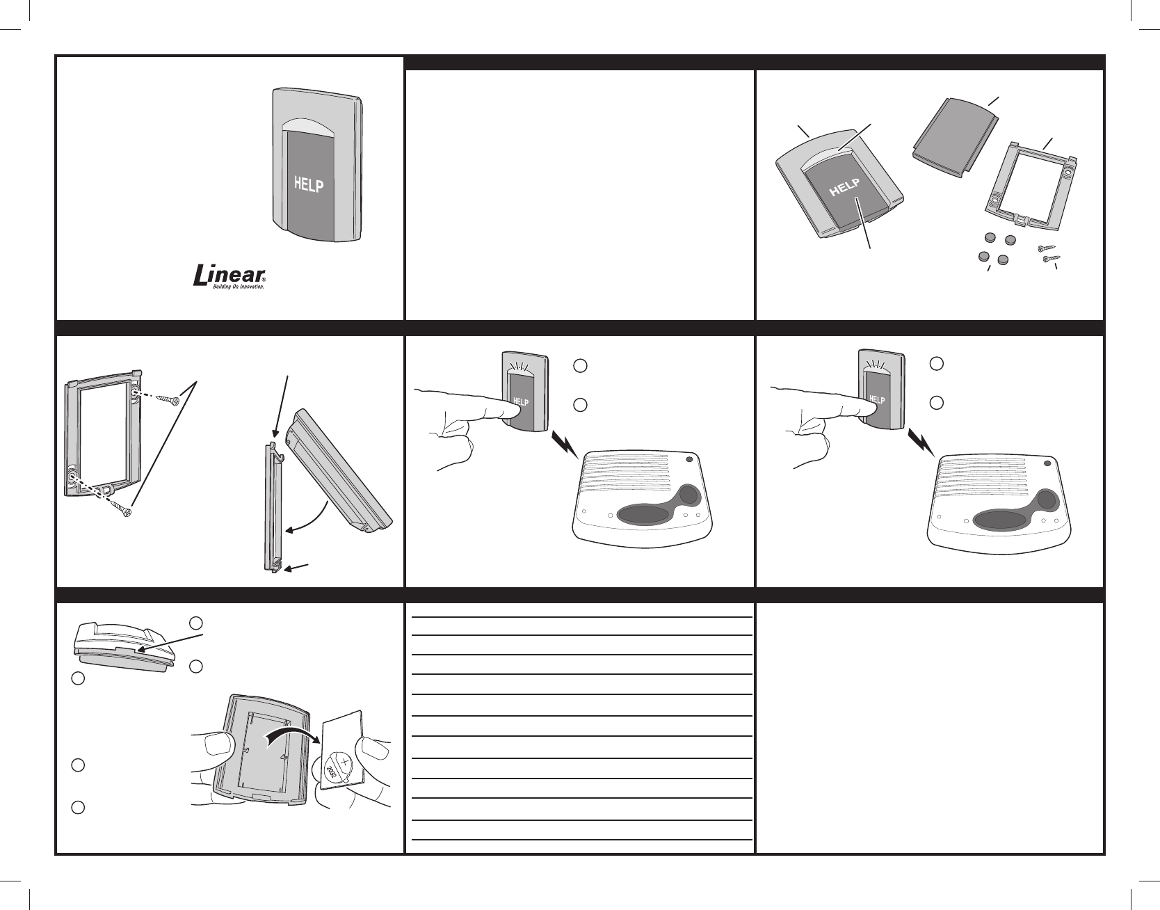
2. FEATURES
3. OPTIONAL WALL MOUNTING 4. PROGRAM TRANSMITTER INTO RECEIVER 5.TESTING TRANSMITTER
6. BATTERY REPLACEMENT OR BUTTON EXCHANGING 7. NOTES LINEAR LIMITED WARRANTY
This Linear product is warranted against defects in material and workmanship for twelve (12) months. This
warranty extends only to wholesale customers who buy direct from Linear or through Linear’s normal
distribution channels. Linear does not warrant this product to consumers. Consumers should inquire from their
selling dealer as to the nature of the dealer’s warranty, if any. There are no obligations or liabilities on the part
of Linear LLC for consequential damages arising out of or in connection with use or performance of this
product or other indirect damages with respect to loss of property, revenue, or profi t, or cost of removal,
installation, or reinstallation. All implied warranties, including implied warranties for merchantability and implied
warranties for fi tness, are valid only until the warranty expires. This Linear LLC Warranty is in lieu of all other
warranties express or implied.
All products returned for warranty service require a Return Product Authorization Number (RPA#). Contact Linear
Technical Services at 1-800-421-1587 for an RPA# and other important details.
IMPORTANT !!!
Linear radio controls provide a reliable communications link and fi ll an important need in portable wireless
signaling. However, there are some limitations which must be observed.
• For U.S. installations only: The radios are required to comply with FCC Rules and Regulations as Part 15
devices. As such, they have limited transmitter power and therefore limited range.
• A receiver cannot respond to more than one transmitted signal at a time and may be blocked by radio signals
that occur on or near their operating frequencies, regardless of code settings.
• Changes or modifi cations to the device may void FCC compliance.
• Infrequently used radio links should be tested regularly to protect against undetected interference or fault.
• A general knowledge of radio and its vagaries should be gained prior to acting as a wholesale distributor or
dealer, and these facts should be communicated to the ultimate users.
USA & Canada (800) 421-1587 & (800) 392-0123
(760) 438-7000 - Toll Free FAX (800) 468-1340
www.linearcorp.com
PRINTER’S INSTRUCTIONS:
INSTR,INSTL,CX-65; LINEAR P/N: 235121X2 - INK: BLACK; MATERIAL: 20# MEAD BOND; SIZE: 11.000” x 8.500”; SCALE: 1-1
CX-65
TRANSMITTER
TRANSMIT
INDICATOR
ACTIVATION
BUTTON
MOUNTING
PLATE
TABLE-TOP
FEET (4)
MOUNTING
SCREWS (2)
OPTIONAL BLANK
AQUA BUTTON
ALERT 1
CONSOLE
PLACE THE CONSOLE OR RECEIVER
INTO TEST MODE
ACTIVATE THE TRANSMITTER,
VERIFY THAT THE SIGNAL WAS
RECEIVED
1
2
NOTE: TO VERIFY THE RADIO
RANGE, BE SURE TO TEST
THE TRANSMITTER FROM THE
INTENDED MOUNTED OR
TABLE-TOP LOCATION
TEST SYSTEM WEEKLY!
EMERGENCY
RESET
ALARM
STATUS TEST
Alert
1
1
2
TWIST A COIN OR SCREWDRIVER IN
THE SLOT ON TOP OF TRANSMITTER
TO OPEN THE CASE
REMOVE THE CASE TOP, BUTTON, SILICONE
SEAL, AND LIFT OUT THE TRANSMITTER
CIRCUIT BOARD
3
4
RE-ASSEMBLE THE UNIT
BY REVERSING THE STEPS
5
TEST THE TRANSMITTER
AFTER RE-ASSEMBLING
REPLACE THE BATTERY WITH
ONE TYPE MAXELL CR2032
200mA HR OR DURACELL DL2032
COIN-CELL BATTERY
PLUS SIDE AWAY FROM THE
CIRCUIT BOARD
ATTACH WALL
MOUNT BRACKET
WITH TWO SCREWS
HOOK TOP OF TRANSMITTER
ONTO THE BRACKET TABS
SWING TRANSMITTER
ONTO BRACKET
TO REMOVE
TRANSMITTER
PRESS TAB ON
BRACKET
FOR NON-WALL MOUNT APPLICATIONS,
STICK THE FOUR ADHESIVE "FEET"
ONTO THE MOUNTING BRACKET
ALERT 1
CONSOLE
PLACE THE CONSOLE OR RECEIVER
INTO PROGRAMMING MODE
ACTIVATE THE TRANSMITTER
TO PROGRAM IT INTO THE
CONSOLE OR RECEIVER
1
2
EMERGENCY
RESET
ALARM
STATUS TEST
Alert
1
Copyright © 2013 Linear LLC 235121 X2