Nortel Networks 2332 802.11 A/B/G Access Point User Manual
Nortel Networks, Inc. 802.11 A/B/G Access Point
Contents
- 1. User Manual
- 2. Users Manual 2
- 3. User Manual 1
User Manual

Part No. NN47250-307 (324136-A)
July 2007
4655 Great America Parkway
Santa Clara, CA 95054
324136-A
Nortel WLAN Access Point 2332 Series
Installation Guide
2
NN47250-307 (324136-A Version 01.02)
Copyright © 2007 Nortel Networks. All rights reserved.
The information in this document is subject to change without notice. The statements, configurations, technical data, and
recommendations in this document are believed to be accurate and reliable, but are presented without express or implied
warranty. Users must take full responsibility for their applications of any products specified in this document. The
information in this document is proprietary to Nortel Networks.
Trademarks
*Nortel Networks, the Nortel Networks logo, and the Globemark are trademarks of Nortel Networks.
*Microsoft, MS, MS-DOS, Windows, and Windows NT are registered trademarks of Microsoft Corporation.
*Adobe and Acrobat Reader are trademarks of Adobe Systems Incorporated.
All other trademarks and registered trademarks are the property of their respective owners.
Restricted rights legend
Use, duplication, or disclosure by the United States Government is subject to restrictions as set forth in subparagraph
(c)(1)(ii) of the Rights in Technical Data and Computer Software clause at DFARS 252.227-7013.
Notwithstanding any other license agreement that may pertain to, or accompany the delivery of, this computer software,
the rights of the United States Government regarding its use, reproduction, and disclosure are as set forth in the
Commercial Computer Software-Restricted Rights clause at FAR 52.227-19.
Statement of conditions
In the interest of improving internal design, operational function, and/or reliability, Nortel Networks. reserves the right to
make changes to the products described in this document without notice.
Nortel Networks does not assume any liability that may occur due to the use or application of the product(s) or circuit
layout(s) described herein.
Portions of the code in this software product may be Copyright © 1988, Regents of the University of California. All
rights reserved. Redistribution and use in source and binary forms of such portions are permitted, provided that the above
copyright notice and this paragraph are duplicated in all such forms and that any documentation, advertising materials,
and other materials related to such distribution and use acknowledge that such portions of the software were developed
by the University of California, Berkeley. The name of the University may not be used to endorse or promote products
derived from such portions of the software without specific prior written permission.
SUCH PORTIONS OF THE SOFTWARE ARE PROVIDED “AS IS” AND WITHOUT ANY EXPRESS OR IMPLIED
WARRANTIES, INCLUDING, WITHOUT LIMITATION, THE IMPLIED WARRANTIES OF
MERCHANTABILITY AND FITNESS FOR A PARTICULAR PURPOSE.

3
Nortel WLAN Access Point 2332 Series Installation Guide
In addition, the program and information contained herein are licensed only pursuant to a license agreement that contains
restrictions on use and disclosure (that may incorporate by reference certain limitations and notices imposed by third
parties).
Legal information
This section includes the following legal information:
•“Limited product warranty” on page 3
•“Nortel Networks software license agreement” on page 5
•“SSH source code statement” on page 6
•“OpenSSL project license statements” on page 6
•“Trademarks” on page 2
Limited product warranty
The following sections describe the Nortel standard Product Warranty for End Users.
Products
WLAN—Security Switch 2300 Series
WLAN—Access Points 2332 Series
Nortel WLAN Location Engine 2340
Limited warranty
Nortel standard warranty for hardware is one (1) year. Nortel warrants software materials to be defect free for
90 Days from time of purchase. Nortel requires purchasing the software subscription if a customer would like
to receive new WLAN—Security Switch 2300 Series, Nortel WLAN — Management System software. This
limited warranty extends only to you the original purchaser of the Product.
Exclusive remedy
Your sole remedy under the limited warranty described above is, at Nortel’s sole option and expense, the
repair or replacement of the non-conforming Product or refund of the purchase price of the non-conforming
Products. Nortel’s obligation under this limited warranty is subject to compliance with Nortel’s then-current
Return Material Authorization (“RMA”) procedures. All replaced Products will become the property of
Nortel. Exchange Products not returned to Nortel will be invoiced at full Product list prices. Replacement
Products may be new, reconditioned or contain refurbished materials. In connection with any warranty
services hereunder, Nortel may in its sole discretion modify the Product at no cost to you to improve its reli-
ability or performance.
Warranty claim procedures
Should a Product fail to conform to the limited warranty during the applicable warranty period as described
above, Nortel must be notified during the applicable warranty period in order to have any obligation under the
limited warranty.

4
NN47250-307 (324136-A Version 01.02)
The End Customer or their designated reseller must obtain a Return Material Authorization number (RMA
number) from Nortel for the non-conforming Product and the non-conforming Product must be returned to
Nortel according to the then-current RMA procedures. The End Customer or their designated reseller is
responsible to ensure that the shipments are insured, with the transportation charges prepaid and that the RMA
number is clearly marked on the outside of the package. Nortel will not accept collect shipments or those
returned without an RMA number clearly visible on the outside of the package.
Exclusions and Restrictions
Nortel shall not be responsible for any software, firmware, information or memory data contained in, stored on
or integrated with any Product returned to Nortel pursuant to any warranty or repair.
Upon return of repaired or replaced Products by Nortel, the warranty with respect to such Products will
continue for the remaining unexpired warranty or sixty (60) days, whichever is longer. Nortel may provide
out-of-warranty repair for the Products at its then-prevailing repair rates.
The limited warranty for the Product does not apply if, in the judgment of Nortel, the Product fails due to
damage from shipment, handling, storage, accident, abuse or misuse, or it has been used or maintained in a
manner not conforming to Product manual instructions, has been modified in any way, or has had any Serial
Number removed or defaced. Repair by anyone other than Nortel or an approved agent will void this warranty.
EXCEPT FOR ANY EXPRESS LIMITED WARRANTIES FROM Nortel Networks SET FORTH ABOVE,
THE PRODUCT IS PROVIDED “AS IS”, AND Nortel Networks AND ITS SUPPLIERS MAKE NO
WARRANTY, EXPRESS, IMPLIED, STATUTORY OR OTHERWISE, WITH RESPECT TO PRODUCT
OR ANY PART THEREOF, INCLUDING WITHOUT LIMITATION ANY IMPLIED WARRANTY OF
TITLE, MERCHANTABILITY, FITNESS FOR A PARTICULAR PURPOSE, NON-INFRINGEMENT, OR
THOSE ARISING FROM COURSE OF PERFORMANCE, DEALING, USAGE OR TRADE. Nortel
Networks’S SUPPLIERS MAKE NO DIRECT WARRANTY OF ANY KIND TO END CUSTOMER FOR
THE LICENSED MATERIALS. NEITHER Nortel Networks NOR ANY OF ITS SUPPLIERS WARRANT
THAT THE LICENSED MATERIALS OR ANY PART THEREOF WILL MEET END CUSTOMER'S
REQUIREMENTS OR BE UNINTERRUPTED, OR ERROR-FREE, OR THAT ANY ERRORS IN THE
PRODUCT WILL BE CORRECTED. SOME STATES/JURISDICTIONS DO NOT ALLOW THE EXCLU-
SION OF IMPLIED WARRANTIES SO THE ABOVE EXCLUSIONS MAY NOT APPLY TO END
CUSTOMER. THIS LIMITED WARRANTY GIVES END CUSTOMER SPECIFIC LEGAL RIGHTS. END
CUSTOMER MAY ALSO HAVE OTHER RIGHTS, WHICH VARY FROM STATE/JURISDICTION TO
STATE/JURISDICTION. TO THE MAXIMUM EXTENT PERMITTED BY APPLICABLE LAW, IN NO
EVENT SHALL Nortel Networks OR ITS SUPPLIERS BE LIABLE FOR THE COST OF PROCUREMENT
OF SUBSTITUTE GOODS OR SERVICES, LOSS OF PROFITS, OR FOR ANY SPECIAL, CONSEQUEN-
TIAL, INCIDENTAL, PUNITIVE OR INDIRECT DAMAGES (OR DIRECT DAMAGES IN THE CASE
OF Nortel Networks’S SUPPLIERS) ON ANY THEORY OF LIABILITY, WHETHER IN CONTRACT,
TORT (INCLUDING WITHOUT LIMITATION NEGLIGENCE), STRICT LIABILITY OR OTHERWISE
ARISING OUT OF OR RELATED TO THE PRODUCT OR ANY USE OR INABILITY TO USE THE
PRODUCT. Nortel Networks’S TOTAL LIABILITY ARISING OUT OF OR RELATED TO THE
PRODUCT, OR USE OR INABILITY TO USE THE PRODUCT, WHETHER IN CONTRACT, TORT
(INCLUDING WITHOUT LIMITATION NEGLIGENCE), STRICT LIABILITY OR OTHERWISE,
SHALL NOT EXCEED THE PRICE PAID FOR THE PRODUCT. THE LIMITATIONS SET FORTH IN
THIS SECTION SHALL APPLY EVEN IF Nortel Networks AND/OR ITS SUPPLIERS ARE ADVISED OF
THE POSSIBILITY OF SUCH DAMAGE, AND NOTWITHSTANDING THE FAILURE OF ESSENTIAL
PURPOSE OF ANY LIMITED REMEDY. Nortel Networks NEITHER ASSUMES NOR AUTHORIZES
ANY OTHER PERSON TO ASSUME FOR IT ANY OTHER LIABILITY IN CONNECTION WITH THE
SALE, INSTALLATION, MAINTENANCE OR USE OF ITS PRODUCTS.

5
Nortel WLAN Access Point 2332 Series Installation Guide
Nortel Networks software license agreement
This Software License Agreement (“License Agreement”) is between you, the end-user (“Customer”) and Nortel
Corporation and its subsidiaries and affiliates (“Nortel Networks”). PLEASE READ THE FOLLOWING CAREFULLY.
YOU MUST ACCEPT THESE LICENSE TERMS IN ORDER TO DOWNLOAD AND/OR USE THE SOFTWARE.
USE OF THE SOFTWARE CONSTITUTES YOUR ACCEPTANCE OF THIS LICENSE AGREEMENT. If you do not
accept these terms and conditions, return the Software, unused and in the original shipping container, within 30 days of
purchase to obtain a credit for the full purchase price.
“Software” is owned or licensed by Nortel, its parent or one of its subsidiaries or affiliates, and is copyrighted and
licensed, not sold. Software consists of machine-readable instructions, its components, data, audio-visual content (such
as images, text, recordings or pictures) and related licensed materials including all whole or partial copies. Nortel grants
you a license to use the Software only in the country where you acquired the Software. You obtain no rights other than
those granted to you under this License Agreement. You are responsible for the selection of the Software and for the
installation of, use of, and results obtained from the Software.
1.Licensed Use of Software. Nortel Networks grants Customer a nonexclusive license to use a copy of the Software on
only one machine at any one time or to the extent of the activation or authorized usage level, whichever is applicable. To
the extent Software is furnished for use with designated hardware or Customer furnished equipment (“CFE”), Customer
is granted a nonexclusive license to use Software only on such hardware or CFE, as applicable. Software contains trade
secrets and Customer agrees to treat Software as confidential information using the same care and discretion Customer
uses with its own similar information that it does not wish to disclose, publish or disseminate. Customer will ensure that
anyone who uses the Software does so only in compliance with the terms of this Agreement. Customer shall not a) use,
copy, modify, transfer or distribute the Software except as expressly authorized; b) reverse assemble, reverse compile,
reverse engineer or otherwise translate the Software; c) create derivative works or modifications unless expressly
authorized; or d) sublicense, rent or lease the Software. Licensors of intellectual property to Nortel are beneficiaries of
this provision. Upon termination or breach of the license by Customer or in the event designated hardware or CFE is no
longer in use, Customer will promptly return the Software to Nortel or certify its destruction. Nortel may audit by remote
polling or other reasonable means to determine Customer’s Software activation or usage levels. If suppliers of third
party software included in Software require Nortel to include additional or different terms, Customer agrees to abide by
such terms provided by Nortel with respect to such third party software.
2.Warranty. Except as may be otherwise expressly agreed to in writing between Nortel Networks and Customer,
Software is provided “AS IS” without any warranties (conditions) of any kind. NORTEL NETWORKS DISCLAIMS
ALL WARRANTIES (CONDITIONS) FOR THE SOFTWARE, EITHER EXPRESS OR IMPLIED, INCLUDING,
BUT NOT LIMITED TO THE IMPLIED WARRANTIES OF MERCHANTABILITY AND FITNESS FOR A
PARTICULAR PURPOSE AND ANY WARRANTY OF NON-INFRINGEMENT. Nortel Networks is not obligated to
provide support of any kind for the Software. Some jurisdictions do not allow exclusion of implied warranties, and, in
such event, the above exclusions may not apply.
3.Limitation of Remedies. IN NO EVENT SHALL NORTEL OR ITS AGENTS OR SUPPLIERS BE LIABLE FOR
ANY OF THE FOLLOWING: a) DAMAGES BASED ON ANY THIRD PARTY CLAIM; b) LOSS OF, OR DAMAGE
TO, CUSTOMER’S RECORDS, FILES OR DATA; OR c) DIRECT, INDIRECT, SPECIAL, INCIDENTAL,
PUNITIVE, OR CONSEQUENTIAL DAMAGES (INCLUDING LOST PROFITS OR SAVINGS), WHETHER IN
CONTRACT, TORT OR OTHERWISE (INCLUDING NEGLIGENCE) ARISING OUT OF YOUR USE OF THE
SOFTWARE, EVEN IF NORTEL NETWORKS, ITS AGENTS OR SUPPLIERS HAVE BEEN ADVISED OF THEIR
POSSIBILITY. The forgoing limitations of remedies also apply to any developer and/or supplier of the Software. Such
developer and/or supplier is an intended beneficiary of this Section. Some jurisdictions do not allow these limitations or
exclusions and, in such event, they may not apply.
4.General
a)If Customer is the United States Government, the following paragraph shall apply: All Nortel Software available under
this License Agreement is commercial computer software and commercial computer software documentation and, in the
event Software is licensed for or on behalf of the United States Government, the respective rights to the software and

6
NN47250-307 (324136-A Version 01.02)
software documentation are governed by Nortel standard commercial license in accordance with U.S. Federal
Regulations at 48 C.F.R. Sections 12.212 (for non-DoD entities) and 48 C.F.R. 227.7202 (for DoD entities).
b)Customer may terminate the license at any time. Nortel may terminate the license if Customer fails to comply with the
terms and conditions of this license. In either event, upon termination, Customer must either return the Software to
Nortel or certify its destruction.
c)Customer is responsible for payment of any taxes, including personal property taxes, resulting from Customer’s use of
the Software. Customer agrees to comply with all applicable laws including all applicable export and import laws and
regulations.
d)Neither party may bring an action, regardless of form, more than two years after the cause of the action arose.
e)The terms and conditions of this License Agreement form the complete and exclusive agreement between Customer
and Nortel.
f)This License Agreement is governed by the laws of the country in which Customer acquires the Software. If the
Software is acquired in the United States, then this License Agreement is governed by the laws of the state of New York.
SSH source code statement
C 1995 - 2004 SAFENET, Inc. This software is protected by international copyright laws. All rights reserved. SafeNet is a registered trademark
of SAFENET, Inc., in the United States and in certain other jurisdictions. SAFENET and the SAFENET logo are trademarks of SAFENET, Inc.,
and may be registered in certain jurisdictions. All other names and marks are property of their respective owners.
Copyright (c) 1983, 1990, 1992, 1993, 1995 The Regents of the University of California. All rights reserved.
THIS SOFTWARE IS PROVIDED BY THE REGENTS AND CONTRIBUTORS ``AS IS'' AND ANY EXPRESS OR IMPLIED WARRANTIES,
INCLUDING, BUT NOT LIMITED TO, THE IMPLIED WARRANTIES OF MERCHANTABILITY AND FITNESS FOR A PARTICULAR PUR-
POSE ARE DISCLAIMED. IN NO EVENT SHALL THE REGENTS OR CONTRIBUTORS BE LIABLE FOR ANY DIRECT, INDIRECT, INCI-
DENTAL, SPECIAL, EXEMPLARY, OR CONSEQUENTIAL DAMAGES (INCLUDING, BUT NOT LIMITED TO, PROCUREMENT OF
SUBSTITUTE GOODS OR SERVICES; LOSS OF USE, DATA, OR PROFITS; OR BUSINESS INTERRUPTION) HOWEVER CAUSED AND
ON ANY THEORY OF LIABILITY, WHETHER IN CONTRACT, STRICT LIABILITY, OR TORT (INCLUDING NEGLIGENCE OR OTHER-
WISE) ARISING IN ANY WAY OUT OF THE USE OF THIS SOFTWARE, EVEN IF ADVISED OF THE POSSIBILITY OF SUCH DAMAGE.
Components of the software are provided under a standard 2-term BSD licence with the following names as copyright holders:
o Markus Friedl
o Theo de Raadt
o Niels Provos
o Dug Song
o Aaron Campbell
o Damien Miller
o Kevin Steves
o Daniel Kouril
o Per Allansson
THIS SOFTWARE IS PROVIDED BY THE AUTHOR ``AS IS'' AND ANY EXPRESS OR IMPLIED WARRANTIES, INCLUDING, BUT NOT
LIMITED TO, THE IMPLIED WARRANTIES OF MERCHANTABILITY AND FITNESS FOR A PARTICULAR PURPOSE ARE DISCLAIMED.
IN NO EVENT SHALL THE AUTHOR BE LIABLE FOR ANY DIRECT, INDIRECT, INCIDENTAL, SPECIAL, EXEMPLARY, OR CONSE-
QUENTIAL DAMAGES (INCLUDING, BUT NOT LIMITED TO, PROCUREMENT OF SUBSTITUTE GOODS OR SERVICES; LOSS OF USE,
DATA, OR PROFITS; OR BUSINESS INTERRUPTION) HOWEVER CAUSED AND ON ANY THEORY OF LIABILITY, WHETHER IN CON-
TRACT, STRICT LIABILITY, OR TORT (INCLUDING NEGLIGENCE OR OTHERWISE) ARISING IN ANY WAY OUT OF THE USE OF THIS
SOFTWARE, EVEN IF ADVISED OF THE POSSIBILITY OF SUCH DAMAGE.
OpenSSL project license statements
Copyright (c) 1998-2002 The OpenSSL Project. All rights reserved.
THIS SOFTWARE IS PROVIDED BY THE OpenSSL PROJECT ``AS IS'' AND ANY EXPRESSED OR IMPLIED WARRANTIES, INCLUDING,
BUT NOT LIMITED TO, THE IMPLIED WARRANTIES OF MERCHANTABILITY AND FITNESS FOR A PARTICULAR PURPOSE ARE DIS-
CLAIMED. IN NO EVENT SHALL THE OpenSSL PROJECT OR ITS CONTRIBUTORS BE LIABLE FOR ANY DIRECT, INDIRECT, INCIDEN-

8
NN47250-307 (324136-A Version 01.02)
Regulatory Compliance Statements for WLAN Access Point 2332 Series
Federal Communications Commission (FCC) Compliance Notices
This section includes the following FCC statements for the WLAN Access Point 2332 Series:
• Class B Interference Statement
• RF Radiation Exposure & Hazard Warning
• Non-Modification Statement
• Deployment Statement
Class B Interference Statement
This equipment has been tested and found to comply with the limits for a Class B digital device, pursuant to Part 15 of
the FCC Rules. These limits are designed to provide reasonable protection against harmful interference in a residential
installation. This equipment generates, uses, and can radiate radio frequency energy and, if not installed and used in
accordance with the instructions, may cause harmful interference to radio communications. However, there is no
guarantee that interference will not occur in a particular installation. If this equipment does cause harmful interference to
radio or television reception, which can be determined by turning the equipment off and on, the user is encouraged to try
to correct the interference by one or more of the following measures:
• Reorient or relocate the receiving antenna.
• Increase the separation between the equipment and receiver.
• Connect the equipment into an outlet on a circuit different from that to which the receiver is connected.
• Consult the dealer or an experienced radio/TV technician for help.
FCC Caution:
This device complies with Part 15 of the FCC Rules. Operation is subject to the following two conditions: (1) This
device may not cause harmful interference, and (2) this device must accept any interference received, including
interference that may cause undesired operation.
RF Radiation Exposure & Hazard Statement
To ensure compliance with FCC RF exposure requirements, this device must be installed in a location such that the
antenna of the device will be greater than 20 cm (8 in.) away from all persons. Using higher gain antennas and types of
antennas not covered under the FCC certification of this product is not allowed. Installers of the radio and end users of
the product must adhere to the installation instructions provided in this manual.
This transmitter must not be co-located or operating in conjunction with any other antenna or transmitter.
Non-Modification Statement
Use only the supplied internal antenna, or external antennas supplied by the manufacturer. Unauthorized antennas,
modifications, or attachments could damage the WLAN Access Point 2332 Series and violate FCC regulations. Any
changes or modifications not expressly approved by the party responsible for compliance could void the user's authority
to operate this equipment. Contact Nortel for a list of approved 2.4 GHz and 5.0 GHz external antennas.
This device must be operated with the CAT-5 Ethernet cable installed on each activated AP 2332 Series Ethernet Port to
ensure compliance with the Class B emissions standards. Failure to comply with this installation requirement may cause
the device to operate in excess of the allowable emissions limits.

9
Nortel WLAN Access Point 2332 Series Installation Guide
Deployment Statement
This product is certified for indoor deployment only. Do not install or use this product outdoors.
Dynamic Frequency Selection (DFS) in the 5.0 GHz UNII bands
The 2332 Series access point has been prohibited, via software, from operating in the 5250 to 5350 MHz and
5470 to 5725 MHz frequency bands for the US and Canada because it cannot meet the DFS requirements as outlined in
the rules of the FCC for Part 15, Subpart E that come into force on July 20, 2007.
The 2332 Series and 2332 Series access points will not be marketed or sold in the US and Canada after July 20, 2007
because they are not compliant with the FCC Part 15, Subpart E rules.
Canadian IC Statement
Operation is subject to the following two conditions in Canada:
1) this device may not cause interference, and
2) this device must accept any interference, including interference that may cause undesired operation of the
device
To prevent radio interference to the licensed service (i.e. co-channel Mobile Satellite systems) this device is intended to
be operated indoors and away from windows to provide maximum shielding. Equipment (or its transmit antenna) that is
installed outdoors is subject to licensing and not supported by the WLAN Access Point 2332 Series.
Because high power radars are allocated as primary users (meaning they have priority) in the 5250-5350 MHz band,
these radars could cause interference and/or damage to license exempt WLAN devices.
European Union and European Free Trade Association (EFTA)
Regulatory Compliance
This equipment may be operated in the countries that comprise the member countries of the European Union and the
European Free Trade Association. These countries, listed in the following paragraph, are referred to as The European
Community throughout this document:
AUSTRIA, BELGIUM, BULGARIA, CYPRUS, CZECH REPUBLIC, DENMARK, ESTONIA, FINLAND, FRANCE,
GERMANY, GREECE, HUNGARY, IRELAND, ITALY, LATVIA, LITHUANIA, LUXEMBOURG, MALTA,
NETHERLANDS, POLAND, PORTUGAL, ROMANIA, SLOVAKIA, SLOVENIA, SPAIN, SWEDEN, UNITED
KINGDOM, ICELAND, LICHTENSTEIN, NORWAY, SWITZERLAND
The WLAN Access Point 2332 Series communicates with a Nortel Networks WLAN - Security Switch using a standard
CAT-5 (Category 5) or higher 10/100 Mbps twisted pair Ethernet cable to provide wireless local area networking
(WLAN) capabilities. The WLAN Access Point 2332 Series includes one 802.11a and one
802.11b/g radio and two 802.11a and two 802.11b/g omnidirectional internal antennas. In addition, the 2332 Series
access point can use optional factory-supplied external omnidirectional and/or directional high-gain antennas, one per
the 802.11b/g and one per the 802.11a radios, as described in the external antenna section of the WLAN Access Point
2332 Series Installation Guide. When using the external antennas, connect them to the reverse-polarity R-SMA
connectors located on the side of the WLAN Access Point 2332 Series.
Declaration of Conformity
Marking by this symbol !

10
NN47250-307 (324136-A Version 01.02)
indicates compliance with the Essential Requirements of the R&TTE Directive of the European Union (1999/5/EC).
This equipment meets the following conformance standards:
Safety: EN 60950-1:2001 + A11:2004
EMC: EN 55022:1998 + A1:2000, EN 55024:1998 + A1:2001 + A2:2003, EN301489-1 V.1.4.1, EN 301489-17 v1.2.1,
CISPR22:1997, CISPR24
Including: EN 61000-3-2, -3-3, -4-2, -4-3, -4-4, -4-5, -4-6 and -4-11. The product is also licensed as required for
additional country specific standards as required for the International Marketplace.
Radio: EN 300-328 v.1.6.1 (2004-11) & EN 301-893 v.1.2.3 (2003-08)
Electromagnetic compatibility and Radio spectrum Matters (ERM); Wideband transmission systems; Data
transmission equipment operating in the 2,4 GHz ISM band and using wide band modulation techniques and
Broadband Radio Access Networks (BRAN); 5 GHz high performance RLAN. Certifications are harmonized to the
EN standards covering essential requirements under article 3.2 of the R&TTE Directive. Compliance includes
testing with antennas as specified in attached table.
SAR: EN 50385:2002
European Community Declaration of Conformity
Bulgaria български
С това, nortel обявява, че този модел на радио на WLAN на 2332 Series, е
със съгласие с съществените изисквания и други важни условия на
директива 1999/5 на европейски съюз
Czech Republic Èesky
Norteltímto prohlašuje, že tento WLAN Radio Model 2332 Series, je ve shodì
se základními požadavky a dalšími pøíslušnými ustanoveními smìrnice 1999/
5/ES.
Denmark Dansk
Undertegnede Nortelerklærer herved, at følgende udstyr WLAN Radio Model
2332 Series, overholder de væsentlige krav og øvrige relevante krav i direktiv
1999/5/EF.
English English
Hereby, Nortel declares that this WLAN Radio Model 2332 Series, is in
compliance with the essential requirements and other relevant provisions of
Directive 1999/5/EC.
Estonia Eesti
Käesolevaga kinnitab Nortelseadme WLAN Radio Model 2332 Series,
vastavust direktiivi 1999/5/EÜ põhinõuetele ja nimetatud direktiivist
tulenevatele teistele asjakohastele sätetele.
Finland Suomi
Nortelvakuuttaa täten että WLAN Radio Model 2332 Series, tyyppinen laite
on direktiivin 1999/5/EY oleellisten vaatimusten ja sitä koskevien direktiivin
muiden ehtojen mukainen.

11
Nortel WLAN Access Point 2332 Series Installation Guide
France Français
Par la présente Norteldéclare que l'appareil WLAN Radio Model 2332 Series,
est conforme aux exigencies essentielles et aux autres dispositions pertinentes
de la directive 1999/5/CE.
Germany Deutsch
Hiermit erklärt Nortel., dass sich das Gerät WLAN Radio Model 2332 Series,
in Übereinstimmung mit den grundlegenden Anforderungen und den übrigen
einschlägigen Bestimmungen der Richtlinie 1999/5/EG befindet.
Greece ΕΛΛΗΝΙΚΗ
ÌÅ ÔÇÍ ÐÁÑÏÕÓÁ Nortel. ÇË.ÍÅÉ ÏÔÉ WLAN Radio Model 2332 Series,
ÓÕÌÌÏÑÖ.ÍÅÔÁÉ ÐÑÏÓ ÔÉÓ ÏÕÓÉ..ÅÉÓ ÁÐÁÉÔÇÓÅÉÓ ÊÁÉ ÔÉÓ
ËÏÉÐÅÓ Ó×ÅÔÉÊÅÓ .ÉÁÔÁÎÅÉÓ ÔÇÓ Ï.ÇÃÉÁÓ 1999/5/ÅÊ.
Hungary Magyar
Alulírott, Nortelnyilatkozom, hogy a WLAN Radio Model 2332 Series,
megfelel a vonatkozó alapvetõ követelményeknek és az 1999/5/EC irányelv
egyéb elõírásainak.
Italy Italiano
Con la presente Norteldichiara che questo WLAN Radio Model 2332 Series, è
conforme ai requisiti essenziali ed alle alter disposizioni pertinenti stabilite
dalla direttiva 1999/5/CE.
Latvia Latviski
Ar šo Norteldeklarç, ka WLAN Radio Model 2332 Series, atbilst Direktîvas
1999/5/EK bûtiskajâm prasîbâm un citiem ar to saistîtajiem noteikumiem.
Lithuania Lietuviø
Šiuo Norteldeklaruoja, kad šis WLAN Radio Model 2332 Series, atitinka
esminius reikalavimus ir kitas 1999/5/EB Direktyvos nuostatas.
Malta Malti
Hawnhekk, Nortel., jiddikjara li dan WLAN Radio Model 2332 Series,
jikkonforma mal-tiijiet essenzjali u ma provvedimenti orajn relevanti li hemm
fid-Dirrettiva 1999/5/EC.
Netherlands Netherlands
Hierbij verklaart Norteldat het toestel WLAN Radio Model 2332 Series, in
overeenstemming is met de essentiële eisen en de andere relevante bepalingen
van richtlijn 1999/5/EG.

12
NN47250-307 (324136-A Version 01.02)
Countries of Operation & Restrictions of Use in the European Community
Operation Using the 2.400 to 2.4835 GHz Channels in the European Community
The professional installer should use the configuration utility provided with this product to verify the current channel of
operation, the expected transmit power level, and to confirm that the device is operating in conformance with the
spectrum usage rules for the selected European Community country. If operation is occurring outside of the allowable
channels as indicated in this guide, then operation of the product must cease immediately and the installer must
consult with the local technical support staff responsible for the wireless network.
This device is intended to be operated in all countries of the European Community. Additional restrictions of use for the
2332 Series access point within the European Community countries in the 2.400 to 2.4835 GHz band are listed below.
• The frequencies associated with channels 1 to 13 in the 2.400 to 2.4835 GHz band are allowed to be used
either indoors or outdoors in all countries of the European Community, except where noted below:
Poland Polski
Niniejszym Nortelooewiadcza, ¿e WLAN Radio Model 2332 Series, jest
zgodny z zasadniczymi wymogami oraz pozosta³ymi stosownymi
postanowieniami Dyrektywy 1999/5/EC.
Portugal Português
Norteldeclara que este WLAN Radio Model 2332 Series, está conforme com
os requisitos essenciais e outras disposições da Directiva 1999/5/CE.
Romania Român
Astfel, Nortel declarã acel acest WLAN Radio Model 2332 Series, este în
conformitate cu cerinþele necesare ºi proviziile alte semnificative de Directive
1999 5 EC.
Slovakia Slovensky
Norteltýmto vyhlasuje, že WLAN Radio Model 2332 Series spåòa základné
požiadavky a všetky príslušné ustanovenia Smernice 1999/5/ES.
Slovenia Slovensko
Nortelizjavlja, da je ta WLAN Radio Model 2332 Series, v skladu z
bistvenimi zahtevami in ostalimi relevantnimi doloèili directive 1999/5/ES.
Spain Español
Por medio de la presente Norteldeclara que el WLAN Radio Model 2332
Series, cumple con los requisitos esenciales y cualesquiera otras disposiciones
aplicables o exigibles de la Directiva 1999/5/CE.
Sweden Svenska
Härmed intygar Nortelatt denna WLAN Radio Model 2332 Series, står I
överensstämmelse med de väsentliga egenskapskrav och övriga relevanta
bestämmelser som framgår av direktiv 1999/5/EG.

13
Nortel WLAN Access Point 2332 Series Installation Guide
•In Greece, Italy, Latvia, and Spain the end-user must apply for a license from the national spectrum authority
to operate this device outdoors. Please consult the Nortel WLAN 2300 Series Outdoor Solutions Guide for
further information regarding restrictions and operating conditions for outdoor configurations.
•In France, the following operation is permitted:
— Outdoor operation is only permitted using the 2.400 - 2.454 GHz band, which includes channels
1 to 7, at a maximum EIRP of 100 mW (20 dBm).
— Outdoor operation is permitted in the 2.400 to 2.4835 GHz band on channels 1 to 13 at a maximum
EIRP of 10 mW (10 dBm).
— Indoor operation is permitted in the 2.400 to 2.4835 GHz band on channels 1 to 13 at a maximum
EIRP of 100 mW (20 dBm).
The 2332 Series, whether using the internal or approved external antennas, is guaranteed to meet this
limit by automatically adjusting the transmit power level through the operating software depending upon
the gain of the selected antenna.
Operation Using the 5.15 to 5.25 GHz, 5.25 to 5.35 GHz, and 5.470 to 5.725 GHz Channels in
the European Community
To remain in conformance with European National spectrum usage laws, follow the channel limitations associated with
the 5 GHz bands as specified in this document. The professional installer should verify the current channel of operation
and the expected transmit power level of the WLAN Access Point 2332 Series to confirm that the device is operating in
conformance with the spectrum usage rules for the European Community country where the unit is being installed. If
operation is occurring outside of the allowable frequencies or above the power levels, as indicated in this guide,
then operation of the product must cease immediately and the installer must consult with the local technical support
staff responsible for the wireless network.
This device is intended to be operated in all countries of the European Community. Additional restrictions of use for the
2332 Series access point within the European Community countries in the 5.15 to 5.25 GHz, 5.25 to 5.35 GHz, and
5.470 to 5.725 GHz bands are listed below.
• This device is restricted to indoor use only when operated in the European Community using the
5.15-5.25 GHz and 5.25-5.35 GHz bands, which includes channels 36, 40, 44, 48, 52, 56, 60 & 64.
• The 5 GHz Turbo Mode feature is not allowed for operation in any European Community country.
•In France, operation is restricted to the 5.15 to 5.25 GHz band. No operation is permitted in either the 5.25 to
5.35 GHz or 5.470 to 5.725 GHz bands because the device is noncompliant with the DFS requirements stated
in EN 301-893 v1.3.1.
•In Italy and Latvia the end-user must apply for a license from the national spectrum authority to operate this
device outdoors. Please consult the Nortel WLAN 2300 Series Outdoor Solutions Guide for further infor-
mation regarding restrictions and operating conditions for outdoor configurations.
14
NN47250-307 (324136-A Version 01.02)
Dynamic Frequency Selection (DFS)
This device implements a DFS feature in accordance with the limits in EN 301-893v1.2.3, Section 4.6 and Annex D,
Tables D.1, D.2 & D.4 for a device operating in the mode defined as “Master”. Section 4.6, Tables 6 and 7 of this
document define the requirements prior to using a channel and during normal operation for a Master device (i.e.,
Interference Detection Threshold, Channel Availability Check Time, Uniform Spreading, Channel Closing Transmission
Time and Channel Move Time). This product qualifies for this category since the maximum achievable transmit power is
greater than 23 dBm per the requirements of Table D.2 in Annex D of the standard.
IEEE 802.11a operation in the 5250 to 5350 MHz and 5470 to 5725 MHz frequency bands is governed by ETSI EN
301-893v1.2.3 and the R&TTE Directive 1999/5/EC. Effective March 31, 2008, EN 301-893 v1.2.3 will be replaced by
EN 301-893v1.3.1. The 2332 Series access point will meet compliance with EN 301-893v1.3.1 by disabling operation,
via software, in the 5250 to 5350 MHz and 5470 to 5725 MHz frequency bands because it cannot meet the DFS
requirements as outlined in EN 301-893v1.3.1.
Transmit Power Control (TPC)
European Regulatory requirements specify that wireless devices must employ Transmit Power Control (TPC) to reduce
the potential for interference to other communication systems operating in the 5 GHz frequency bands. This device
includes a provision for adjustment of Transmit Power in accordance with the limits in EN 301-893v1.2.3, Sections 4.3.1
and 4.3.2.
Korea MIC Compliance Statement.
Possible radio wave interference during operation of concerned radio equipment.
Taiwan Compliance Statement
15
Nortel WLAN Access Point 2332 Series Installation Guide
Administrative Rules for Low-power Radio-Frequency Devices
Article 12
For those low-power radio-frequency devices that have already received a type-approval, companies, business units or
users should not change its frequencies, increase its power or change its original features and functions.
Article 14
The operation of the low-power radio-frequency devices is subject to the conditions that no harmful interference is
caused to aviation safety and authorized radio station; and if interference is caused, the user must stop operating the
device immediately and can't re-operate it until the harmful interference is clear.
The authorized radio station means a radio-communication service operating in accordance with COMMUNICATION
ACT.
The operation of the low-power radio-frequency devices is subject to the interference caused by the operation of an
authorized radio station, by another intentional or unintentional radiator, by industrial, scientific and medical (ISM)
equipment, or by an incidental radiator.
5GHz warning statement
This equipment is limited to indoor use.
External Antenna Statement
Intentional radiators, such as the Nortel WLAN Access Point 2332 Series are not intended to be operated with any
antenna(s) other than those furnished by Nortel. An intentional radiator may only be operated with the antenna(s) with
which it is authorized. For a complete listing of the authorized antennas for use with this product, visit
http://www.nortel.com/support
In order to ensure continued compliance, use of an antenna not on the Nortel approved antenna list is not allowed
without specific authorization from Nortel. For additional questions or inquiries regarding specific antennas, contact
Nortel at 1-800-4NORTEL (1-800-466-7835), and use express routing code (ERC) 1572.
Use of an antenna not specifically authorized by Nortel may not comply with local regulatory requirements with respect
to radiated emission limits and may result in illegal operation of the product. The installer of the wireless system and
associated antenna is required to ensure that only those antennas on the Nortel approved antenna list or those antennas
specifically approved by Nortel on a case by case basis are deployed with the intentional radiator.
Be sure to associate the appropriate antenna model number and localized regulatory region when selecting the Nortel
authorized antenna(s).

16
NN47250-307 (324136-A Version 01.02)
Country Specific External Antenna Restrictions
The following list of countries cannot use the Nortel approved antennas listed in the table. Use of these
antennas would violate the local regulatory rules and approved certifications for that country or operation is
not allowed in the specified frequency bands.
Country 2.4 GHz 5.0 GHz
Costa Rica ALL antenna models
Indonesia ALL antenna models
Japan S2403BHN36RSM
S2403BPXN36RSM S51514WPN36RSM
S2406PN36RSM
S241290PN36RSM
SR24120DN36RSM
Korea S2406PN36RSM S51514WPN36RSM
S2409PN36RSM
PC2415NA36RSM
S241290PN36RSM
SR24120DN36RSM
Nigeria ALL antenna models
Russian Federation ALL antenna models
Thailand ALL antenna models

17
Nortel WLAN Access Point 2332 Series Installation Guide
Contents
How to get help . . . . . . . . . . . . . . . . . . . . . . . . . . . . . . . . . . . . . . . . . . . . 19
Introducing the Nortel WLAN 2332 Series System . . . . . . . . . . . . . . . . 21
Nortel WLAN 2332 Series system . . . . . . . . . . . . . . . . . . . . . . . . . . . . . . . . . . . . . 21
Documentation . . . . . . . . . . . . . . . . . . . . . . . . . . . . . . . . . . . . . . . . . . . . . . . . . . . 22
Safety and advisory notices . . . . . . . . . . . . . . . . . . . . . . . . . . . . . . . . . . . . . . 23
Text and syntax conventions . . . . . . . . . . . . . . . . . . . . . . . . . . . . . . . . . . . . . . 23
AP overview . . . . . . . . . . . . . . . . . . . . . . . . . . . . . . . . . . . . . . . . . . . . . . . 25
External hardware features . . . . . . . . . . . . . . . . . . . . . . . . . . . . . . . . . . . . . . . . . . 26
Cable ports . . . . . . . . . . . . . . . . . . . . . . . . . . . . . . . . . . . . . . . . . . . . . . . . . . . 28
Kensington security slot . . . . . . . . . . . . . . . . . . . . . . . . . . . . . . . . . . . . . . . . . 28
AP mounting options . . . . . . . . . . . . . . . . . . . . . . . . . . . . . . . . . . . . . . . . . . . . 28
Status LEDs . . . . . . . . . . . . . . . . . . . . . . . . . . . . . . . . . . . . . . . . . . . . . . . . . . 28
Installing and connecting an 2332 Series . . . . . . . . . . . . . . . . . . . . . . . 31
Unpacking an AP . . . . . . . . . . . . . . . . . . . . . . . . . . . . . . . . . . . . . . . . . . . . . . . . . . 31
Installation requirements and recommendations . . . . . . . . . . . . . . . . . . . . . . . . . . 32
WLAN Management software network plan and work orders . . . . . . . . . . . . . 32
WSS recommendation . . . . . . . . . . . . . . . . . . . . . . . . . . . . . . . . . . . . . . . . . . 33
Wall installation recommendations . . . . . . . . . . . . . . . . . . . . . . . . . . . . . . . . . 33
AP Radio Safety Advisories . . . . . . . . . . . . . . . . . . . . . . . . . . . . . . . . . . . . . . 33
Radio Frequency Exposure . . . . . . . . . . . . . . . . . . . . . . . . . . . . . . . . . . . . . . . 33
Additional radio safety advisories . . . . . . . . . . . . . . . . . . . . . . . . . . . . . . . 34
Cable requirements . . . . . . . . . . . . . . . . . . . . . . . . . . . . . . . . . . . . . . . . . . . . . 34
Installing an 2332 Series . . . . . . . . . . . . . . . . . . . . . . . . . . . . . . . . . . . . . . . . . . . . 35
Installation hardware and tools . . . . . . . . . . . . . . . . . . . . . . . . . . . . . . . . . . . . 35
Suspended ceiling installation—flush ceiling tiles . . . . . . . . . . . . . . . . . . . . . . 37
Suspended ceiling installation—drop ceiling tiles . . . . . . . . . . . . . . . . . . . . . . 41
Junction box installation . . . . . . . . . . . . . . . . . . . . . . . . . . . . . . . . . . . . . . . . . 46
Solid wall or ceiling installation . . . . . . . . . . . . . . . . . . . . . . . . . . . . . . . . . . . . 49
Connecting an AP to a WSS . . . . . . . . . . . . . . . . . . . . . . . . . . . . . . . . . . . . . . . . . 53
Verifying AP health . . . . . . . . . . . . . . . . . . . . . . . . . . . . . . . . . . . . . . . . . . . . . . . . 55

18 Contents
NN47250-307 (324136-A Version 01.02)
External Antennas . . . . . . . . . . . . . . . . . . . . . . . . . . . . . . . . . . . . . . . . . . 57
External antenna selector guide for the 2332 Series for indoor operation . . . 59
Antenna selection decision trees . . . . . . . . . . . . . . . . . . . . . . . . . . . . . . . . . . 63
Dual-Band 802.11a/b/g (2.4/5.0 GHz) . . . . . . . . . . . . . . . . . . . . . . . . . . . . . . . 65
Antenna descriptions – 802.11a (5.0 GHz) antennas . . . . . . . . . . . . . . . . . . . 66
Antenna descriptions – 802.11b/g (2.4 GHz) antennas . . . . . . . . . . . . . . . . . 75
2.4/5.0 GHz Dual antenna . . . . . . . . . . . . . . . . . . . . . . . . . . . . . . . . . . . . . . . . 99
Glossary of common antenna terminology . . . . . . . . . . . . . . . . . . . . . . . . . . 106
AP troubleshooting. . . . . . . . . . . . . . . . . . . . . . . . . . . . . . . . . . . . . . . . 107
AP technical specifications . . . . . . . . . . . . . . . . . . . . . . . . . . . . . . . . . 109
Translated caution statement, warning conventions and warning mes-
sages. . . . . . . . . . . . . . . . . . . . . . . . . . . . . . . . . . . . . . . . . . . . . . . . . . . . 113
Index . . . . . . . . . . . . . . . . . . . . . . . . . . . . . . . . . . . . . . . . . . . . . . . . . . . . 121

19
Nortel WLAN Access Point 2332 Series Installation Guide
How to get help
This section explains how to get help for Nortel products and services.
Getting help from the Nortel web site
The best way to get technical support for Nortel products is from the Nortel Technical
Support Web site:
http://www.nortel.com/support
This site provides quick access to software, documentation, bulletins, and tools to address
issues with Nortel products. More specifically, the site enables you to:
download software, documentation, and product bulletins
search the Technical Support Web site and the Nortel Knowledge Base for answers to
technical issues
sign up for automatic notification of new software and documentation for Nortel
equipment
open and manage technical support cases
Getting help over the phone from a Nortel solutions center
If you don’t find the information you require on the Nortel Technical Support Web site, and
have a Nortel support contract, you can also get help over the phone from a Nortel Solutions
Center.
In North America, call 1-800-4NORTEL (1-800-466-7835).
Outside North America, go to the following Web site to obtain the phone number for your
region:
http://www.nortel.com/callus

20 How to get help
NN47250-307 (324136-A Version 01.02)
Getting help from a specialist by using an express routing code
To access some Nortel Technical Solutions Centers, you can use an Express Routing Code
(ERC) to quickly route your call to a specialist in your Nortel product or service. To locate
the ERC for your product or service, go to:
http://www.nortel.com/erc
Getting help through a Nortel distributor or reseller
If you purchased a service contract for your Nortel product from a distributor or authorized
reseller, contact the technical support staff for that distributor or reseller.
21
Nortel WLAN Access Point 2332 Series Installation Guide
Introducing the Nortel WLAN 2332
Series System
This guide shows you how to install a Nortel Access Point (AP) in a Nortel WLAN 2332 Series System.
Read this guide if you are a network administrator or other person installing an AP in a network.
Nortel WLAN 2332 Series system
The Nortel WLAN 2332 Series System is an enterprise-class WLAN solution that seamlessly integrates with an existing
wired enterprise network. The Nortel system provides secure connectivity to both wireless and wired users in large envi-
ronments such as office buildings, hospitals, and university campuses.
The Nortel WLAN 2332 Series System fulfills the three fundamental requirements of an enterprise WLAN: It eliminates
the distinction between wired and wireless networks, allows users to work safely from anywhere (secure mobility), and
provides a comprehensive suite of intuitive tools for planning and managing the network before and after deployment,
greatly easing the operational burden on IT resources.
The Nortel WLAN 2332 Series System consists of the following components:
•WLAN Management Software tool suite—A full-featured graphical user interface (GUI) client application used
to plan, configure, and deploy a WLAN and manage the users. It also provides a centralized service application for
the WLAN to allow for user monitoring, reporting, and diagnostics
•One or more WLAN—Security Switches (WSSs) —Distributed, intelligent machines for managing user
connectivity, connecting and powering Access Points (APs), and connecting the WLAN to the wired network
backbone
•Multiple Access Point (AP) —Wireless access points that transmit and receive radio frequency (RF) signals to and
from wireless users and connect them to a WSS
•WLAN 2300 System Software (WSS Software)—The operating system that controls all WSSs and APs in a
WLAN. It is accessible through a command-line interface (CLI), or the WLAN Management Software GUI
Nortel WLAN 2332 Series system . . . . . . . . . . . . . . . . . . . . . . . . . . . . . . . . . . . . . . . 21
Documentation . . . . . . . . . . . . . . . . . . . . . . . . . . . . . . . . . . . . . . . . . . . . . . . . . . . . . . . 22
Note. The 2332-A1 is for use in the US & Canada and the 2332-E1 is for use in the EU
countries.

22 Introducing the Nortel WLAN 2332 Series System
NN47250-307 (324136-A Version 01.02)
Documentation
Consult the following documents to plan, install, configure, and manage a Nortel WLAN 2332 Series System.
Planning, configuration, and deployment
Nortel WLAN Management Software 2332 Series User Guide: This document provides instructions for planning,
configuring, deploying, and managing the entire WLAN with the WLAN Management Software tool suite. Read this
guide to learn how to plan wireless services, how to configure and deploy Nortel equipment to provide those services,
and how to optimize and manage your WLAN.
Nortel WLAN Management Software 2300 Series Reference Guide: Detailed instructions and information for all WLAN
Management Software planning, configuration, and management features.
Installation
•Nortel WLAN Security Switch 2300 Series Quick Start Guide: Instructions for performing basic setup of secure
(802.1X) and guest (Web AAA) access, for configuring a Mobility Domain for roaming, and for accessing a sample
network plan in the WLAN Management Software for advanced configuration and management
•Nortel WLAN—Security Switch 2300 Series Installation and Basic Configuration Guide: Instructions and
specifications for installing a WSS in a Nortel WLAN 2332 Series System, and basic instructions for deploying a
secure IEEE 802.11 wireless service
•Nortel WLAN—Access Point 2332 Installation Guide: Instructions and specifications for installing an AP and
connecting it to a WSS
Configuration and management
•Nortel WLAN Management System 2300 Series Reference Guide: Instructions for planning, configuring, deploying,
and managing the entire WLAN with the WLAN Management Software tool suite
•Nortel WLAN—Security Switch 2332 Series Configuration Guide: Instructions for configuring and managing the
system through the WSS Software CLI
•Nortel WLAN—Security Switch 2300 Series Command Line Reference: Functional and alphabetical reference to all
WSS Software commands supported on WSSs and APs
Introducing the Nortel WLAN 2332 Series System 23
Nortel WLAN Access Point 2332 Series Installation Guide
Safety and advisory notices
The following kinds of safety and advisory notices appear in this manual. (For translations of the warning conventions
and of all warnings in this manual, see Appendix , “Translated caution statement, warning conventions and warning
messages,” on page 113.)
Text and syntax conventions
Nortel manuals use the following text and syntax conventions:
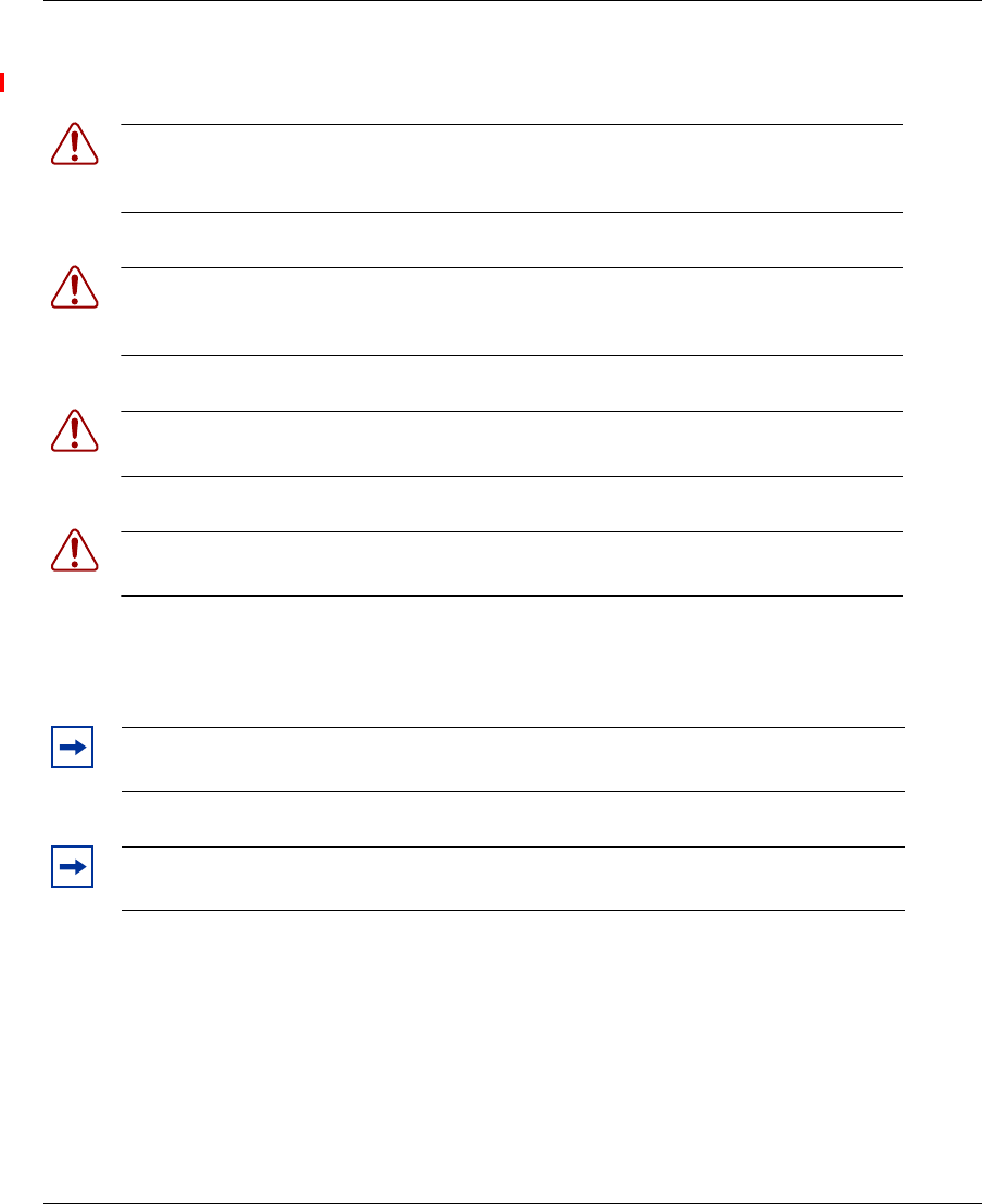
Caution! This situation or condition can lead to data loss or damage to the product or
other property.
Warning! This situation or condition can cause injury.
Warning! High voltage. This situation or condition can cause injury due to
electric shock.
Note. This information is of special interest.
Convention Use
Monospace text Sets off command syntax or sample commands and system
responses.
Bold text Highlights commands that you enter or items you select.
Italic text Designates command variables that you replace with
appropriate values, or highlights publication titles or words
requiring special emphasis.
Menu Name > Command Indicates a menu item that you select. For example, File > New
indicates that you select New from the File menu.
[ ] (square brackets) Enclose optional parameters in command syntax.
{ } (curly brackets) Enclose mandatory parameters in command syntax.
| (vertical bar) Separates mutually exclusive options in command syntax.

24 Introducing the Nortel WLAN 2332 Series System
NN47250-307 (324136-A Version 01.02)
25
Nortel WLAN Access Point 2332 Series Installation Guide
AP overview
A Nortel Access Point (AP) provides IEEE 802.11 wireless access to the network. APs are designed for use with a
Nortel WLAN—Security Switch (WSS). APs require hardware installation only. All configuration for an AP takes place
on the WSS.
The WLAN Access Point 2332 Series (2332-E1 and 2332-A1) communicate with a Nortel Networks WLAN - Security
Switch using a standard CAT-5 (Category 5) or higher 10/100 Mbps twisted pair Ethernet cable to provide wireless local
area networking capabilities. The WLAN Access Point 2332 Series includes one 802.11a and one 802.11b/g radio and
two 802.11a and two 802.11b/g omnidirectional internal antennas. In addition, the 2332 Series access points can use
optional factory-supplied external omnidirectional and/or directional high-gain antennas, one per the 802.11b/g and one
per the 802.11a radios, as described in the external antenna section of this document.
When using the external antennas, connect them to the reverse-polarity R-SMA connectors located on the side of the
WLAN Access Point 2332 Series model.
External hardware features . . . . . . . . . . . . . . . . . . . . . . . . . . . . . . . . . . . . . . . . . . . . . 26
Warning! Installation must be performed by qualified service personnel only. Read and
follow all warning notices and instructions marked on the product or included in the
documentation. (For translations of this warning, see “Qualified service personnel warning”
on page 115.)
26 AP overview
NN47250-307 (324136-A Version 01.02)
External hardware features
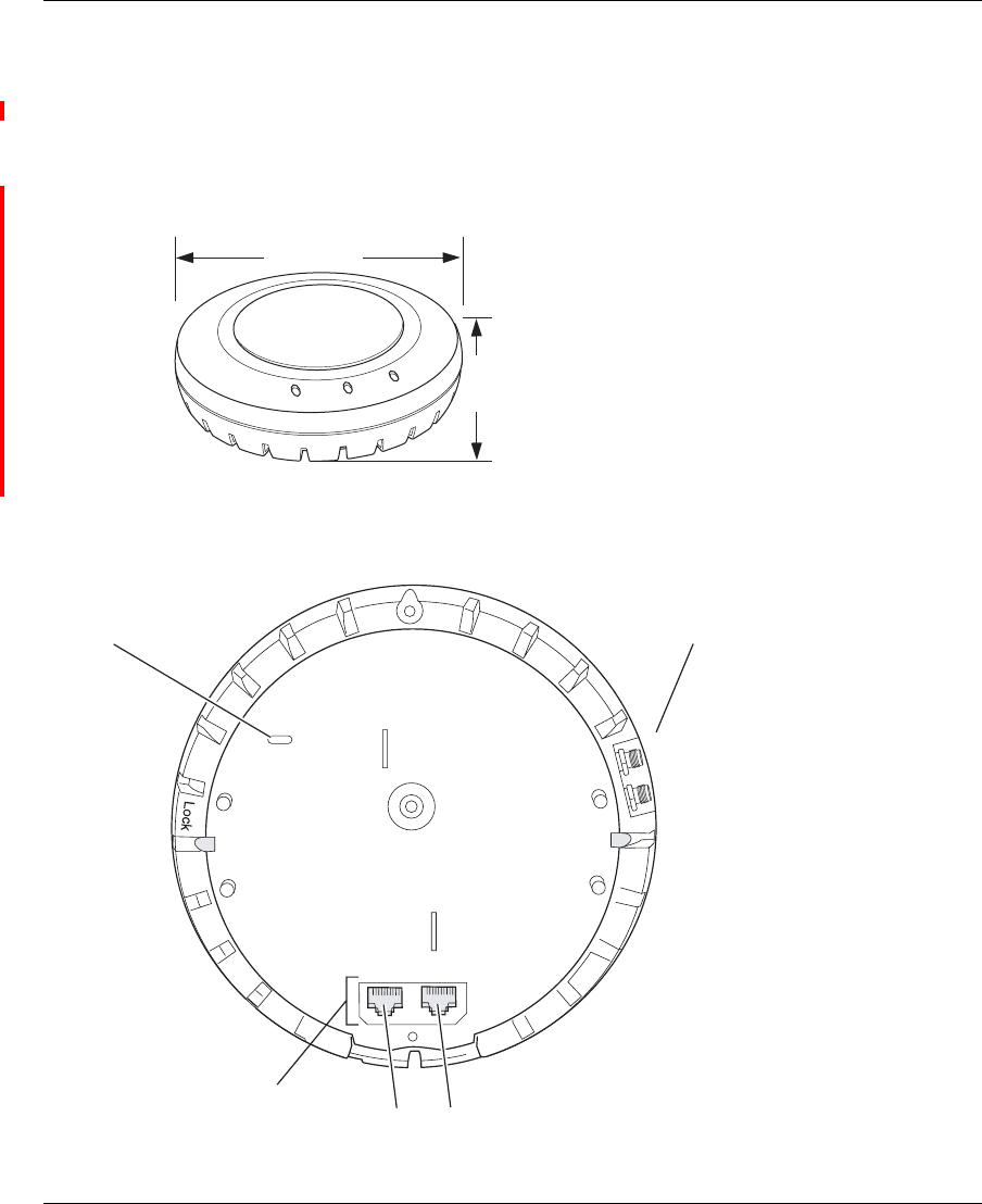
Figure 1 and Figure 2 show the external hardware features of the 2332.
Figure 1. AP Model —Top View
Figure 2. AP Model 2332 Series—Bottom View
840-9502-0040
Diameter
16.76 cm
(6.6 inches)
Height
6.10 cm
(2.4 inches)
External antenna
connectors
840-9502-0007
Unlock
RJ-45
port Port 1
Kensington security
slot
802.11a
802.11b/g
Port 2
s

AP overview 27
Nortel WLAN Access Point 2332 Series Installation Guide
28 AP overview
NN47250-307 (324136-A Version 01.02)
Cable ports
The 2332 Series has two RJ-45 ports. (Figure 2 on page 26.) Each port provides a 10/100BASE-TX Ethernet connection
to an WSS. The connection can be direct to an WSS or indirect through an intermediate Layer 2 or Layer 3 network.
The AP receives power and data through the RJ-45 ports. Use a Category 5 (Cat 5) cable with straight-through signaling
and standard RJ-45 connectors to connect an AP to an WSS or other device in the network. The 2332 Series supports
802.3af, and also can receive PoE from Nortel switches and Nortel-approved power injectors.
The two RJ-45 ports support dual-homed configurations for redundancy. An AP uses only one link for booting, configu-
ration, and data transfer. If the link becomes unavailable, the AP can reboot using the other link. The ports are identical
except for logical numbering (1 or 2). You can use either port to connect an AP to an WSS. However, an AP always
attempts to boot on AP port 1 first. Only if the boot attempt on port 1 fails does the AP attempt to boot on port 2. If one
port become s unavailable, the other port can provide full power to the AP.
Kensington security slot
Models 2332 Series2332 Serieshave a slot to attach a Kensington security cable. The cable is not included with the 2332
Series.
AP mounting options
You can mount an AP access point on any of the following types of surfaces:
• Suspended T-bar ceiling
• Junction box
• Solid surface wall or ceiling
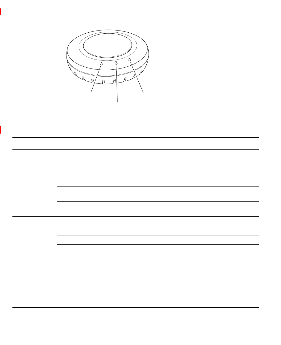
Status LEDs
The AP has LEDs that provide status information of the device. Figure 3 shows the locations of the LEDs. Table 1
describes the LEDs.
Warning! APs do not support daisy-chain configurations. Do not connect the 2332
Series to another 2332 Series through the second RJ-45 port.
Note. The solid surface mounting option requires Cat-5 cable that does not have strain
relief. The other mounting options can use Cat-5 cable with or without strain relief.
AP overview 29
Nortel WLAN Access Point 2332 Series Installation Guide
Figure 3. Health and Radio LEDs—2332 Series
Table 1: Access Point LEDs—2332 Series
LED Appearance Meaning
Health Solid green All the following are true:
• Management link with a WSS is operational.
• AP has booted.
• AP has received a valid configuration from a WSS.
• At least one radio is enabled or is in sentry mode.
Solid amber AP is waiting to receive boot instructions and a
configuration file from a WSS.
Alternating green and
amber
AP is booting and receiving its configuration file from a
WSS.
Radio 1
Radio 2
Solid green A client is associated with the radio.
Blinking green Associated client is sending or receiving traffic.
Blinking amber Non-associated client is sending or receiving traffic.
Alternating green and
amber
Radio is unable to transmit. This state can occur due to any
of the following:
• Excessive radio interference in the environment is
preventing the radio from sending beacons.
• The radio has failed.
Unlit Means one of the following:
• Radio is disabled.
• Radio is enabled, but no clients are associated with the
radio and there is no traffic activity.
Radio 2 LED
Health LED
Radio 1 LED
840-9502-0010

30 AP overview
NN47250-307 (324136-A Version 01.02)
31
Nortel WLAN Access Point 2332 Series Installation Guide
Installing and connecting an 2332
Series
Unpacking an AP
The shipping carton for an AP contains the following items:
•One AP
• Mounting kit:
• One universal mounting bracket (attached to the AP)
• One paper mounting template (used for marking the cutting areas and screw hole locations)
• One two-piece 14.2-mm (9/16-inch) T-bar clamp
• One two-piece 15.9-mm (5/8-inch) T-bar clamp
• One two-piece 23.9-mm (15/16-inch) T-bar clamp
• Two #6 sheet metal screws and two drywall anchors
• Three adhesive rubber feet
• One documentation pack that includes the following documents:
•Nortel WLAN
—Access Point 2332 Series Quick Installation Guide
• Nortel WLAN 2332 Series Access Point Mounting Template
• Nortel WLAN 2300 Series Outdoor Solution Guide
Unpacking an AP . . . . . . . . . . . . . . . . . . . . . . . . . . . . . . . . . . . . . . . . . . . . . . . . . . . . . 31
Installation requirements and recommendations . . . . . . . . . . . . . . . . . . . . . . . . . . . . . 32
Installing an 2332 Series . . . . . . . . . . . . . . . . . . . . . . . . . . . . . . . . . . . . . . . . . . . . . . . 35
Connecting an AP to a WSS . . . . . . . . . . . . . . . . . . . . . . . . . . . . . . . . . . . . . . . . . . . . 53
Verifying AP health . . . . . . . . . . . . . . . . . . . . . . . . . . . . . . . . . . . . . . . . . . . . . . . . . . . 55
Note. Before installing an AP, you might need to generate a network plan and an AP
work order with WLAN Management Software . (See “WLAN Management software
network plan and work orders” on page 32.)
32 Installing and connecting an 2332 Series
NN47250-302 (324136-A Version 01.02)
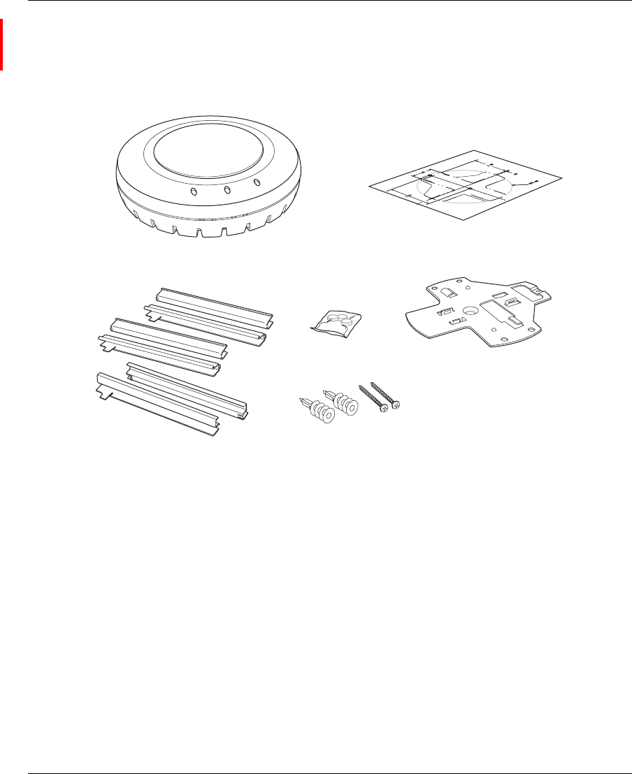
Figure 4 shows the contents of the shipping carton for model 2332 Series.
Figure 4. 2332 Series Shipping Carton Contents
Before you begin installation:
1Open the carton and carefully remove the contents, if you have not already done so.
2Place the packing materials back in the carton and save the carton.
3Verify that you received each item in the previous list. If any item is missing or damaged, contact Nortel.
Installation requirements and recommendations
For best results, follow these requirements and recommendations before installing an AP.
WLAN Management software network plan and work orders
If you are using the WLAN Management Software to plan your Nortel Mobility System installation, you might want to
create and verify a network plan for the entire Nortel network installation and generate an AP work order, before
T-bar clamps
Mounting template
Rubber feet Universal
mounting bracket
Mounting hardware
Access Point
840-9502-0001
Installing and connecting an 2332 Series 33
Nortel WLAN Access Point 2332 Series Installation Guide
installing any access points. A network plan and the AP work orders provide the following information about AP instal-
lation and configuration:
• Number of APs required for adequate WLAN capacity in each coverage area
• Detailed installation location for each AP
• Settings for all APs in the WLAN
(For information about installing WLAN Management Software , creating and verifying a network plan, and generating
an AP work order, see the Nortel WLAN Management Software 2300 Series User Guide and Nortel WLAN Management
Software 2300 Series Reference Guide.)
WSS recommendation
Nortel recommends that you install and configure the WSS before installing an AP. If the switch is already installed and
configured for the access points, you can immediately verify the cable connection when you plug the cable into the
RJ-45 port on the AP.
(For information about connecting an AP to a WSS port, see “Connecting an AP to a WSS” on page 53.)
Wall installation recommendations
If you plan to install an AP on a partial wall or other vertical surface, orient the top of the access point (the side with the
LEDs) toward the intended coverage area. The radio antennas transmit through the top of the access point but not
through the bottom (where the bracket is located).
AP Radio Safety Advisories
When you enable the AP radio(s) as part of WSS configuration, the radios are able to receive and transmit radio
frequency energy as soon as you connect the AP to the WSS, either directly or through the network.
Radio Frequency Exposure
Federal Communications Commission (FCC) Docket 96-8 for Spread Spectrum Transmitters specifies a safety standard
for human exposure to radio frequency electromagnetic energy emitted by FCC-certified equipment. Nortel 2332 Series
products meet the uncontrolled environmental limits found in OET-65 and ANSI C95.1-1991, if proper installation
procedures are followed. To ensure compliance with these exposure requirements, this device must be installed in such a
manner as to maintain a minimum of 20 cm separation distance between the radiating element(s) and all persons.
Caution! AP models 2332 Series are designed to receive power only from an
802.3af-compliant source, a Nortel WLAN—Security Switch (WSS), or a Nortel-approved
power injector. Connecting an AP to a Power over Ethernet (PoE) device that is not
approved by Nortel can damage the equipment.
34 Installing and connecting an 2332 Series
NN47250-302 (324136-A Version 01.02)
Additional radio safety advisories
(For translations of these warnings, see “Radio safety warnings” on page 116.)
Cable requirements
Standard Cat-5 Ethernet cabling is required for use with the 2332 Series.
Cat-5 cable with straight-through signaling must be installed at the site before you install an access point. A single
connection requires one cable.
Table 2 lists the pin signals for the 10/100 Ethernet straight-through wiring. Pins 4, 5, 7, and 8 are used when Nortel
Power over Ethernet (PoE) is enabled on the port. RD stands for Receive Data and TD stands for Transmit Data.
Warning! Install this device in such a manner as to maintain a minimum of 20 cm (7.9
inches) separation distance between the radiating element(s) and all persons. This safety
warning conforms with FCC radio frequency exposure limits.
Warning! Do not operate the AP near unshielded blasting caps or in an otherwise
explosive environment unless the device has been modified for such use by qualified
personnel.
Warning! Do not touch or move the AP when the antennas are transmitting or
receiving.
Warning! Before using a wireless device in a hazardous location, consult the local
codes, national codes, and safety directors of the location for usage constraints.
Note. The 2332 Series is intended for indoor use only. Do not install the device nor
operate it outdoors.
Note. To reduce the possibility of connection interference caused by dust, clean the
Cat-5 connector pins before inserting a cable into an AP.

Installing and connecting an 2332 Series 35
Nortel WLAN Access Point 2332 Series Installation Guide
Mounting an 2332 Series on a solid surface requires using a Cat-5e cable that does not have strain relief. For installation
on all other surfaces, you can use the Cat-5e cable with or without strain relief.
(For more information about cables, see “Cable ports” on page 28.)
Installing an 2332 Series
To install an 2332 Series, use one of the procedures in this section.
Installation hardware and tools
Table 3 lists the mounting hardware and tools required for each type of installation.
Table 2: 10/100 Ethernet Straight-Through Pin Signals
WSS Other Device
Pin Function Pin Function
1RD+1TD+
2RD-2TD-
3TD+3RD+
4PoE+4PoE+
5PoE+5PoE+
6TD-6RD-
7PoE-7PoE-
8PoE-8PoE-
36 Installing and connecting an 2332 Series
NN47250-302 (324136-A Version 01.02)
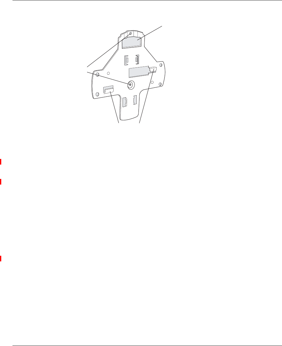
Figure 5 shows the universal mounting bracket.
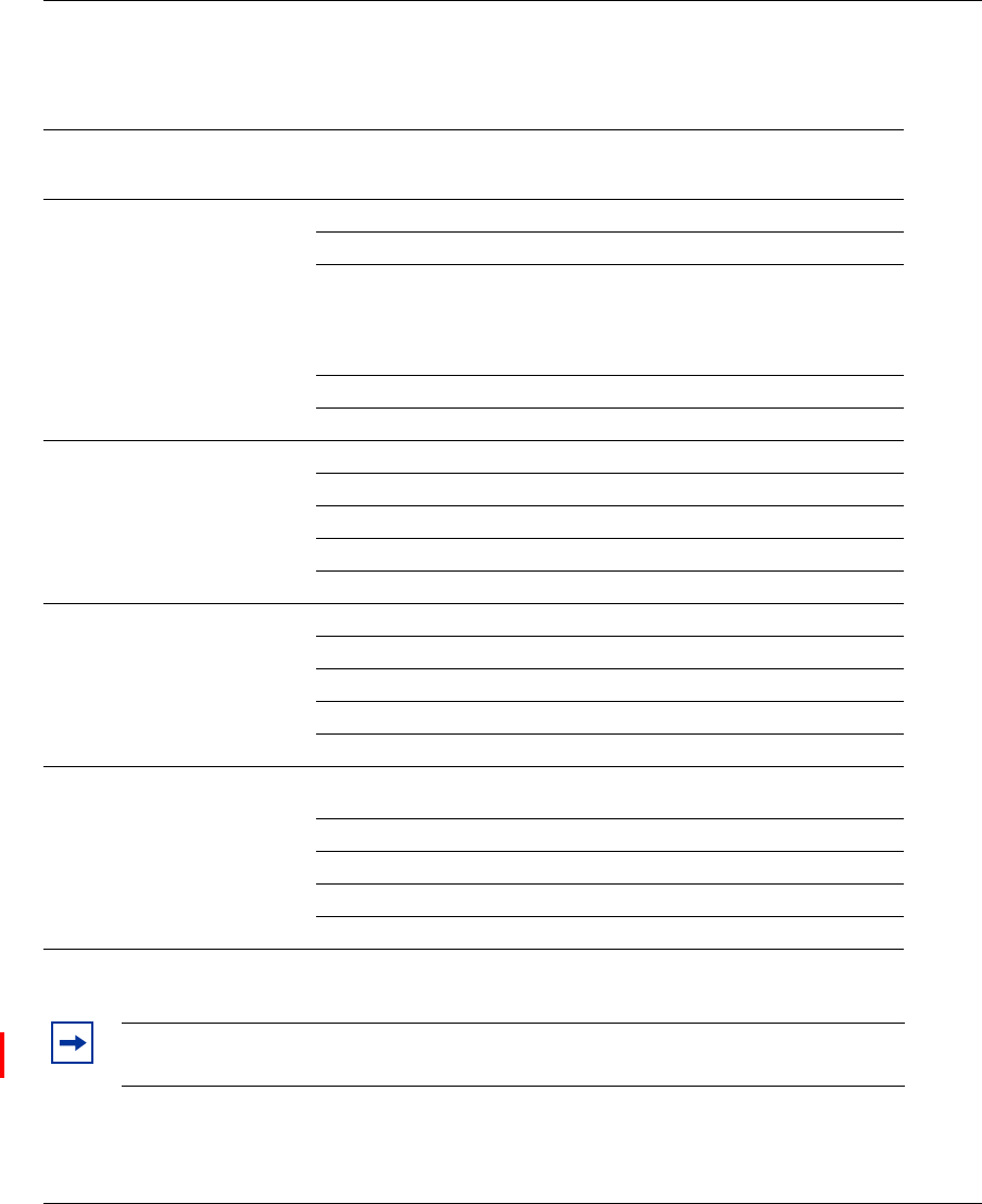
Table 3: Required Mounting Hardware and Tools—
Model 2332 Series
Mounting Option Required Hardware and Tools Included with the
Product
Suspended ceiling—flush ceiling
tiles
Mounting template Yes
Universal mounting bracket Yes
T-bar clamp
Note: A T-bar clamp is not required for a
23.9-mm (15/16-inch) T-bar ceiling with
flush ceiling tiles.
Yes
Box cutter No
Small screwdriver (3-mm or 1/8-inch) No
Suspended ceiling—drop ceiling
tiles
Mounting template Yes
Universal mounting bracket Yes
T-bar clamp Yes
Box cutter No
Small screwdriver (3-mm or 1/8-inch) No
Junction box Junction box No
Two #6-32 x 1-inch machine screws Yes
Universal mounting bracket Yes
Small screwdriver (3-mm or 1/8-inch) No
#2 Phillips-head screwdriver No
Solid wall or ceiling Two #6 sheet metal screws and two drywall
anchors
Yes
Universal mounting bracket Yes
Hammer No
Small screwdriver (3-mm or 1/8-inch) No
#2 Phillips-head screwdriver No
Note. Model 2332 Series is plenum rated, so it can also be installed in the space above
the ceiling if preferred.
Installing and connecting an 2332 Series 37
Nortel WLAN Access Point 2332 Series Installation Guide
Figure 5. Universal Mounting Bracket
Suspended ceiling installation—flush ceiling tiles
(For required mounting hardware and tools, see Table 3 on page 36.)
1Select an installation location that is centered over a T-bar in the ceiling.
2Cut a hole as follows in the ceiling tile for the Cat-5 cable:
aPlace the mounting template over the area where you plan to install the AP.
bUse the box cutter to cut along the line marking the opening for the port connector.
cRemove the mounting template and the material you cut from the ceiling panel.
3Determine whether to install a T-bar clamp onto the ceiling T-bar:
• If the T-bar width is 14.2 mm (9/16 inches), you need to install the 14.2-mm (9/16-inch) T-bar
clamp. Go to step 4.
• If the T-bar width is 23.9 mm (15/16 inches), the universal mounting bracket fits directly onto the
T-bar. Go to step 5.
4Install the 14.2-mm (9/16-inch) T-bar clamp onto the ceiling T-bar as shown in Figure 6 on page 38.
aSlide each half of the clamp onto the T-bar so that the clamp lip is fully on the T-bar.
bSlide the two halves of the clamp toward each other until the tabs are inserted completely into the
holes and the clamp fits snugly on the T-bar.
840-9502-0018
Port connector
opening
T-bar flanges
Screw holes
38 Installing and connecting an 2332 Series
NN47250-302 (324136-A Version 01.02)
Figure 6. Step 4—Installing a T-bar Clamp
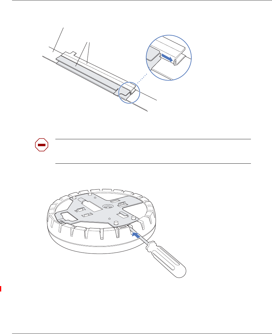
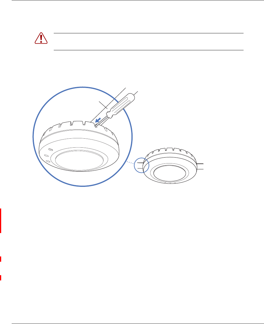
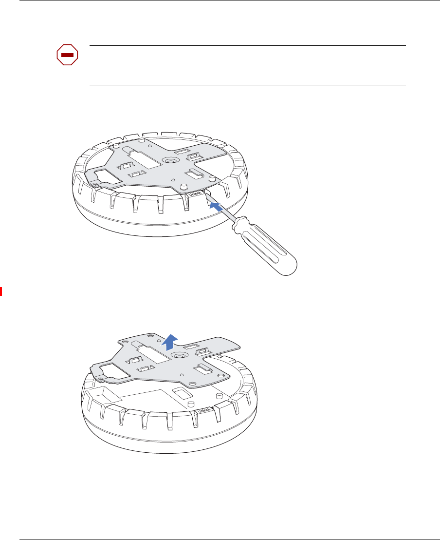
5Unlock the universal mounting bracket from the AP by inserting the 3-mm or 1/8-inch screwdriver into
the Unlock hole on the AP as shown in Figure 7.
Figure 7. Step 5—Unlocking the Bracket
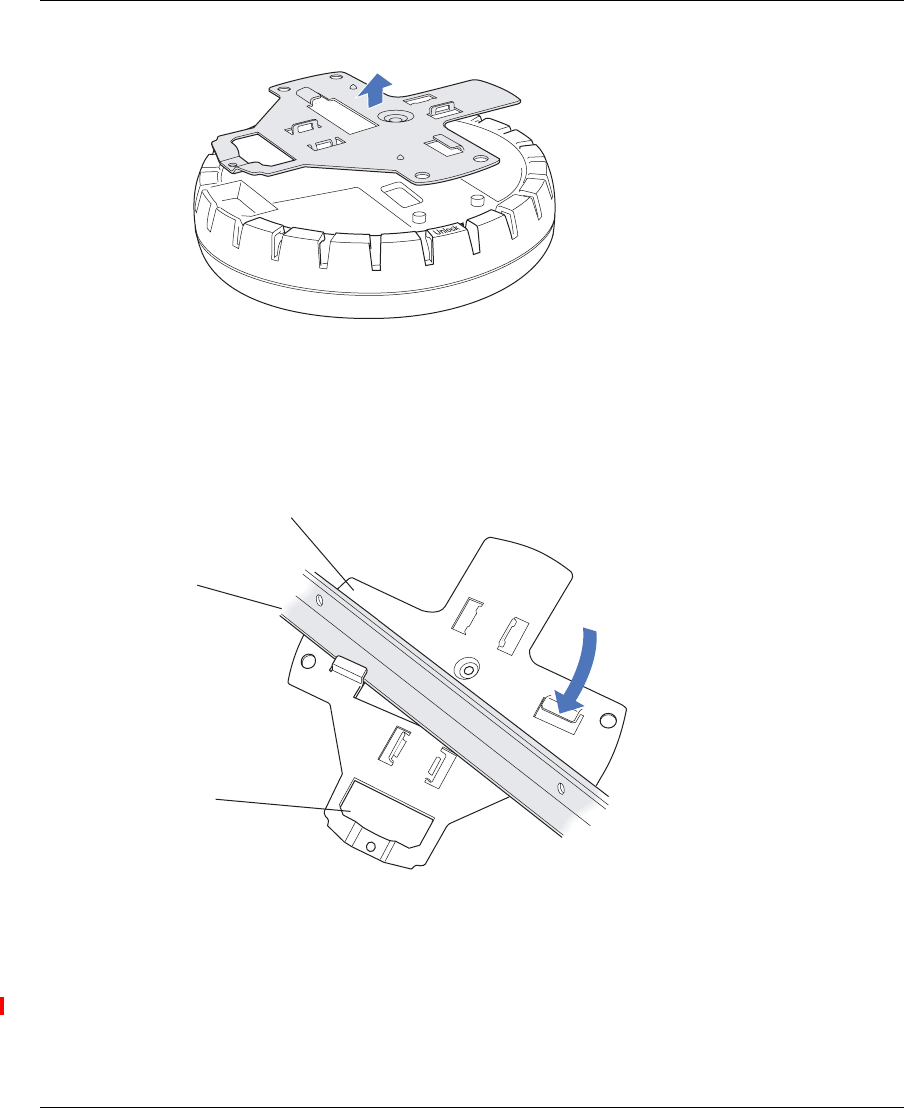
6Remove the bracket as shown in Figure 8 on page 39.
Caution! To avoid damage to the AP’s lock mechanism or electronic
components, do not use excessive force when inserting a tool into the Unlock or
Lock hole.
T-bar
T-bar clamp halves
Slide together
840-9502-0003
840-9502-0011
Installing and connecting an 2332 Series 39
Nortel WLAN Access Point 2332 Series Installation Guide
Figure 8. Step 6—Removing the Bracket
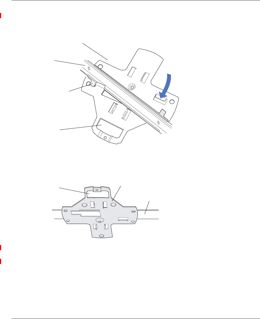
7Install the universal mounting bracket as follows onto the T-bar or T-bar clamp:
aAs shown in Figure 9, place the universal mounting bracket against the T-bar or clamp so that the
two screw holes face downward and the two T-bar flanges face upward and are adjacent to the T-bar
edges.
Figure 9. Step 7—Top View
bProperly align the bracket for mounting by placing the bracket so that its port connector opening is
to the left of the hole you cut for the cables.
cRotate the universal mounting bracket clockwise until the flanges snap into place on the T-bar or
clamp as shown in Figure 10 on page 40.
840-9502-0008
T-bar
(Viewed from above ceiling tiles, looking down.)
840-9502-0005
Universal mounting
bracket
Port connector
opening
40 Installing and connecting an 2332 Series
NN47250-302 (324136-A Version 01.02)
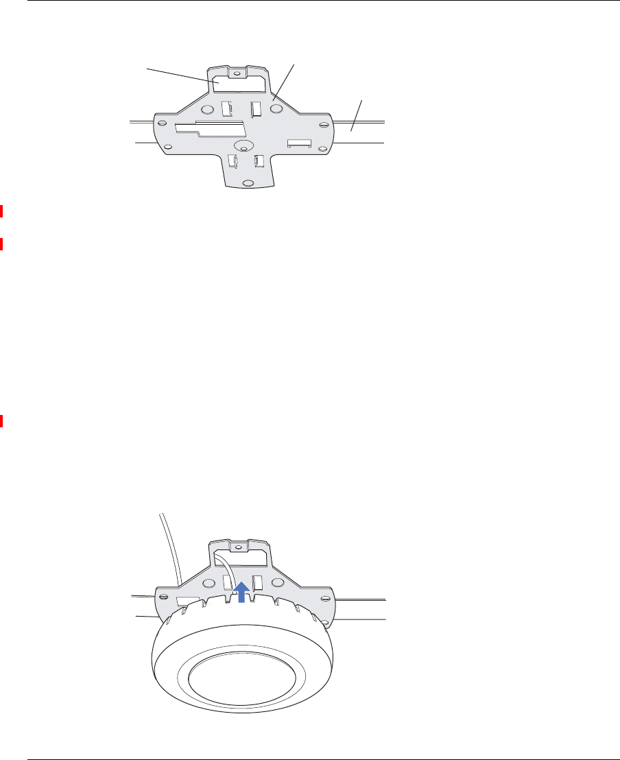
Figure 10. Step 7—Bottom View
8Pull the Cat-5 cable about 15 cm (about 6 inches) out of the hole in the ceiling tile and through the port
connector opening to create enough slack to insert the cable.
9Insert the Cat-5 cable into the connector:
10 Install the Kensington lock (optional).
aLoop the Kensington lock’s cable around an object that cannot be moved or damaged by a person
pulling on the cable.
bInsert the key into the Kensington lock.
cInsert the Kensington lock into the security slot on the AP.
dRotate the key right or left to secure the lock to the AP.
ePull on the lock to verify that it is secured to the AP.
fRemove the key.
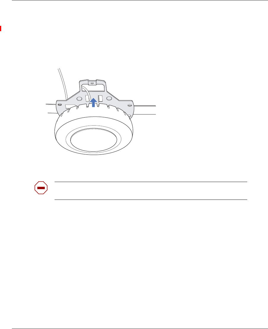
11 Lift the AP into place on the universal mounting bracket as shown in Figure 11 on page 40.
Make sure the cable feeds properly into the ceiling as you lift the device, and does not become trapped
between the access point and the bracket.
Figure 11. Step 11—Placing the AP on the Bracket
T- b a r
Universal mounting bracket
840-9502-0004
Port connector
opening
840-9502-0002
Installing and connecting an 2332 Series 41
Nortel WLAN Access Point 2332 Series Installation Guide
12 Lock the AP onto the bracket by inserting the 3-mm or 1/8-inch screwdriver into the Lock hole on the
access point as shown in Figure 12.
Figure 12. Step 12—Locking the Bracket
13 To ensure that the AP is fully locked onto the bracket, gently pull down on the access point and attempt to
rotate it from side to side.
14 If the access point comes off the bracket, relock the device onto the bracket as described in step 12 on
page 41.
15 If the other end of the Cat-5 cable is not already connected and the link activated, go to “Connecting an
AP to a WSS” on page 53. Otherwise, go to “Verifying AP health” on page 55.
Suspended ceiling installation—drop ceiling tiles
(For required mounting hardware and tools, see Table 3 on page 36.)
1Select an installation location that is centered over a T-bar in the ceiling.
2Cut a hole as follows in the ceiling tile for the Cat-5 cable:
aPlace the mounting template over the area where you plan to install the AP.
bUse the box cutter to cut along the line marking the opening for the point connectors.
cRemove the mounting template and the material you cut from the ceiling panel.
3Install the T-bar clamp that fits the T-bar:
Warning! To prevent possible damage to the AP, make sure the device is fully
locked onto the bracket before releasing it.
840-9502-0006
Lock
T-bar
42 Installing and connecting an 2332 Series
NN47250-302 (324136-A Version 01.02)
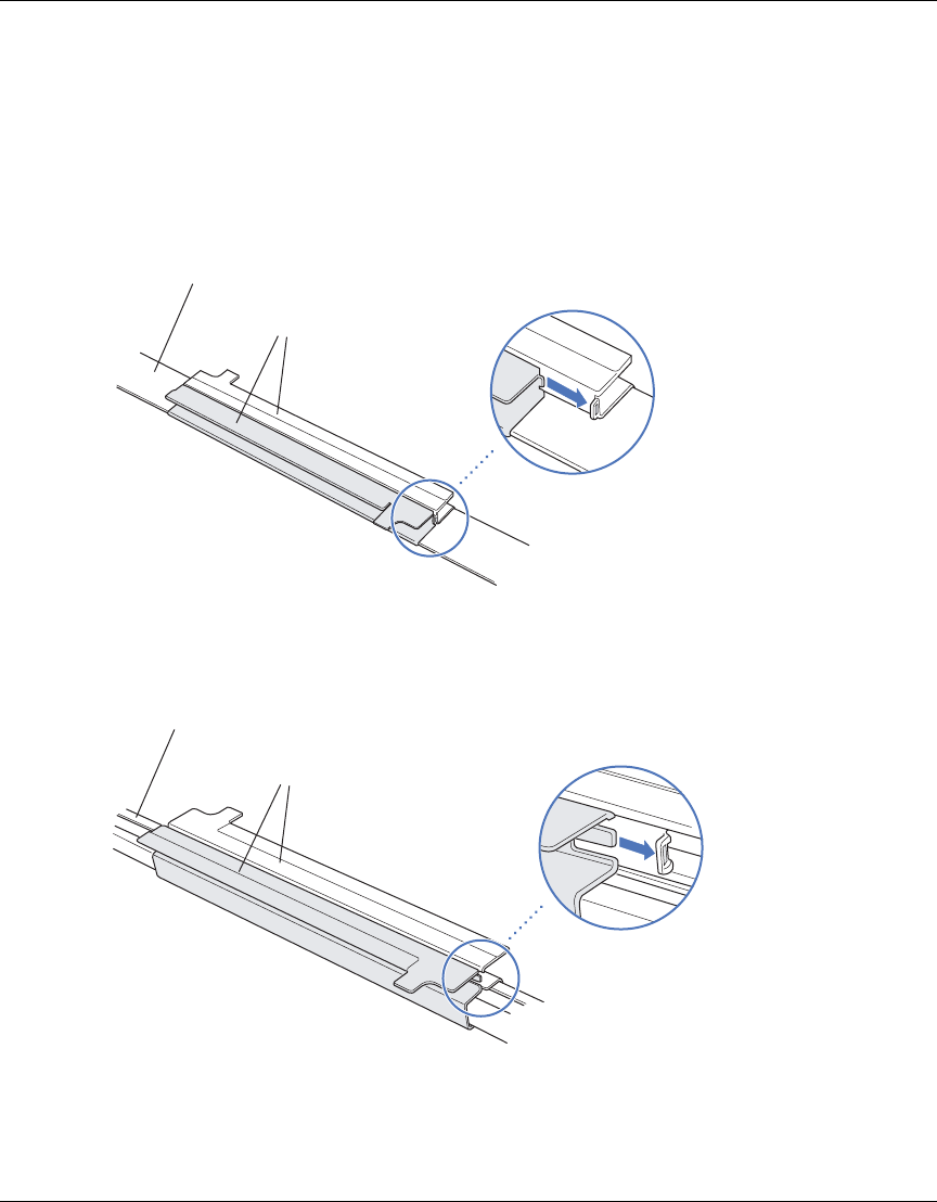
aSlide each half of the clamp onto the T-bar so that the clamp lip is fully on the T-bar.
bSlide the two halves of the clamp toward each other until the tabs are inserted completely into the
holes and the clamp fits snugly on the T-bar.
Figure 13 shows an example for a 23.9-mm (15/16-inch) T-bar. Figure 14 shows an example for a
15.9-mm (5/8-inch) T-bar.
Figure 13. Step 3—Installing the T-bar Clamp for a 23.9-mm (15/16-inch)
T-bar
Figure 14. Step 3—Installing the T-bar Clamp for a 15.9-mm (5/8-inch)
T-bar
T-bar
T-bar clamp halves
Slide together
840-9502-0003
T-bar
T-bar clamp halves
Slide together
840-9502-0066
Installing and connecting an 2332 Series 43
Nortel WLAN Access Point 2332 Series Installation Guide
4Unlock the universal mounting bracket from the AP by inserting the 3-mm or 1/8-inch screwdriver into
the Unlock hole on the AP as shown in Figure 15.
Figure 15. Step 4—Unlocking the Bracket
5Remove the bracket as shown in Figure 16 on page 43.
Figure 16. Step 5—Removing the Bracket
6Install the universal mounting bracket as follows onto the T-bar clamp:
aAs shown in Figure 17, place the universal mounting bracket against the T-bar clamp so that the two
screw holes face downward and the two T-bar flanges face upward and are adjacent to the T-bar
edges.
bProperly align the bracket for mounting by placing the bracket so that its port connector opening is
to the left of the hole you cut for the cables.
Caution! To avoid damage to the AP’s lock mechanism or electronic
components, do not use excessive force when inserting a tool into the Unlock or
Lock hole.
840-9502-0011
840-9502-0008
44 Installing and connecting an 2332 Series
NN47250-302 (324136-A Version 01.02)
cRotate the universal mounting bracket clockwise until the flanges snap into place on the T-bar clamp
as shown in Figure 18 on page 44.
Figure 17. Step 6—Top View
Figure 18. Step 6—Bottom View
7Pull the Cat-5 cable about 15 cm (about 6 inches) out of the hole in the ceiling tile and through the port
connector opening to create enough slack to insert the cable.
8Insert the Cat-5 cable into the connector.
9Install the Kensington lock (optional).
aLoop the Kensington lock’s cable around an object that cannot be moved or damaged by a person
pulling on the cable.
bInsert the key into the Kensington lock.
cInsert the Kensington lock into the security slot on the AP.
dRotate the key right or left to secure the lock to the AP.
T- bar
T-bar clamps
(attached
to T-bar)
Universal mounting
bracket
840-9502-0012
(Viewed from above ceiling tiles, looking down.)
Port connector
opening
T- b a r
Universal mounting bracket
840-9502-0004
Port connector
opening
Installing and connecting an 2332 Series 45
Nortel WLAN Access Point 2332 Series Installation Guide
ePull on the lock to verify that it is secured to the AP.
fRemove the key.
10 Lift the AP into place on the universal mounting bracket as shown in Figure 19 on page 45.
Make sure the cable feeds properly into the ceiling as you lift the device, and does not become trapped
between the access point and the bracket.
Figure 19. Step 9—Placing the AP on the Bracket
11 Lock the AP onto the bracket by inserting the 3-mm or 1/8-inch screwdriver into the Lock hole on the
access point as shown in Figure 20.
Caution! To prevent possible damage to the AP, make sure the device is fully
locked onto the bracket before releasing it.
840-9502-0002
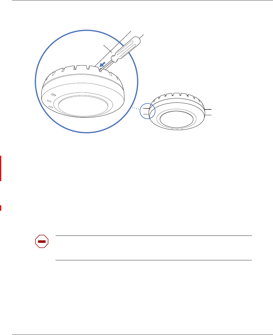
46 Installing and connecting an 2332 Series
NN47250-302 (324136-A Version 01.02)
Figure 20. Step 10—Locking the Bracket
12 To ensure that the AP is fully locked onto the bracket, gently pull down on the access point and attempt to
rotate it from side to side.
If the access point comes off the bracket, relock the device onto the bracket as described in step 11 on
page 40.
13 If the other end of the Cat-5 cable is not already connected and the link activated, then go to “Connecting
an AP to a WSS” on page 53. Otherwise, go to “Verifying AP health” on page 55.
Junction box installation
(For required mounting hardware and tools, see Table 3 on page 36.)
1Unlock the universal mounting bracket from the AP by inserting the 3-mm or 1/8-inch screwdriver into
the Unlock hole on the AP as shown in Figure 21.
Caution! To avoid damage to the AP’s lock mechanism or electronic
components, do not use excessive force when inserting a tool into the Unlock or
Lock hole.
840-9502-0006
Lock
T-bar
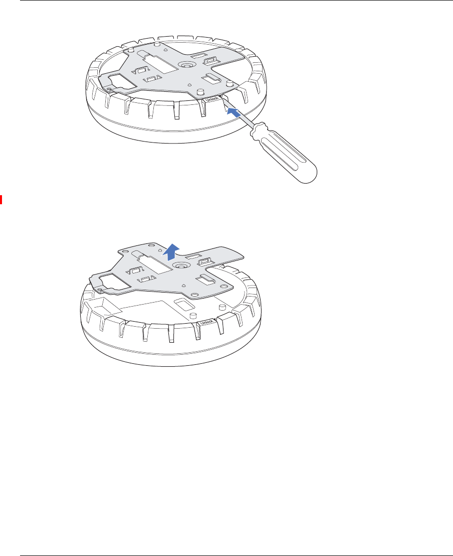
Installing and connecting an 2332 Series 47
Nortel WLAN Access Point 2332 Series Installation Guide
Figure 21. Step 1—Unlocking the Bracket
2Remove the bracket as shown in Figure 22 on page 47.
Figure 22. Step 2—Removing the Bracket
3Attach the universal mounting bracket to the junction box as shown in Figure 23:
aPlace the universal mounting bracket against the junction box so that the two screw holes face the
junction box and align over the screw holes in the box.
bInsert the #6-32 x 1-inch machine screws in the universal mounting bracket’s screw holes, and use a
#2 Phillips-head screwdriver to tighten them.
840-9502-0011
840-9502-0008
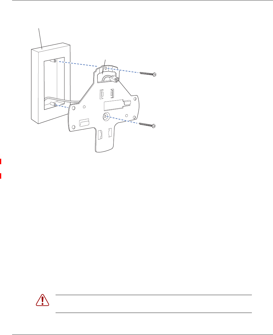
48 Installing and connecting an 2332 Series
NN47250-302 (324136-A Version 01.02)
Figure 23. Step 3—Placing the Bracket on the Junction Box
4Pull the Cat-5 cable about 15 cm (about 6 inches) out of the junction box and through the port connector
opening to create enough slack to insert the cable into the port connector.
5Insert the Cat-5 cable into the connector.
6Install the Kensington lock (optional).
aLoop the Kensington lock’s cable around an object that cannot be moved or damaged by a person
pulling on the cable.
bInsert the key into the Kensington lock.
cInsert the Kensington lock into the security slot on the AP.
dRotate the key right or left to secure the lock to the AP.
ePull on the lock to verify that it is secured to the AP.
fRemove the key.
7Lift the AP into place on the universal mounting bracket.
Make sure the cable feeds properly into the junction box as you lift the device, and does not become
trapped between the access point and the bracket.
8Lock the AP onto the bracket by inserting the 3-mm or 1/8-inch screwdriver into the Lock hole on the
access point as shown in Figure 24.
Warning! To prevent possible damage to the AP, make sure the device is fully
locked onto the bracket before releasing it.
840-9502-0017
Junction box
Port connector
opening
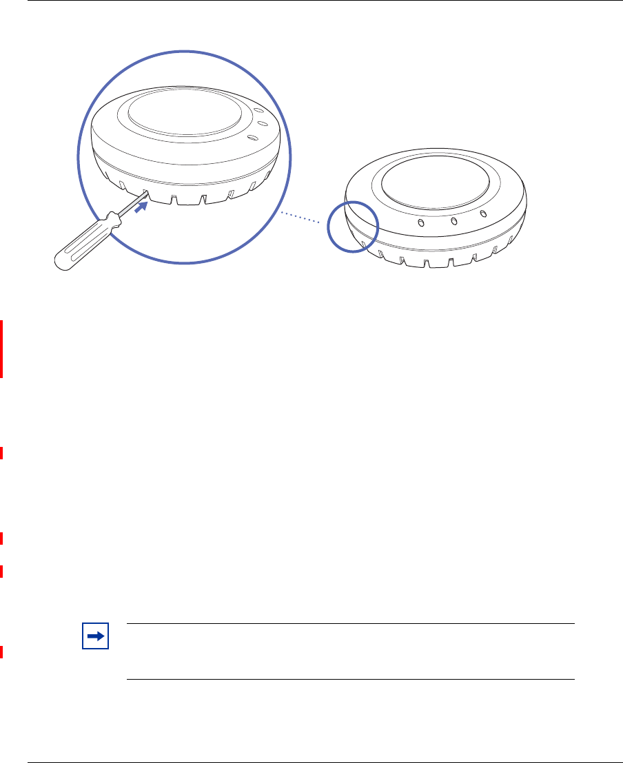
Installing and connecting an 2332 Series 49
Nortel WLAN Access Point 2332 Series Installation Guide
Figure 24. Step 7—Locking the Bracket
9To ensure that the AP is fully locked onto the bracket, gently pull down on the access point and attempt to
rotate it from side to side.
If the access point comes off the bracket, relock the device onto the bracket as described in step 8 on
page 48.
10 If the other end of the Cat-5 cable is not already connected and the link activated, go to “Connecting an
AP to a WSS” on page 53. Otherwise, go to “Verifying AP health” on page 55.
Solid wall or ceiling installation
(For required mounting hardware and tools, see Table 3 on page 36.)
1Prepare holes in the wall or ceiling for the universal mounting bracket, using the following steps:
aPlace the paper mounting template over the location where you want to install the AP.
bMark the screw hole location(s).
❥If you plan to route the Cat-5 cable externally along the wall or ceiling, mark the locations of
both the center screw hole and the screw hole by the port connector opening.
❥If you plan to route the Cat-5 cable through a hole in the wall or ceiling, mark the location of
the center screw hole only. You cannot use the screw hole by the port connector opening if you
cut a hole for the opening.
cRemove the template.
2Install the drywall anchor(s):
Note. Do not mark the four holes on the edges of the bracket. (These are the
holes indicated by the dashed lines in Figure 27 on page 51.) The AP fits into
these holes. They are not screw holes.
840-9502-0062
Lock

50 Installing and connecting an 2332 Series
NN47250-302 (324136-A Version 01.02)
aInsert a drywall anchor into each hole, up to the beginning of the threads on the anchor.
bScrew each anchor the rest of the way into its hole using a #2 Phillips-head screwdriver.
cRemove the screw from each anchor and save the screw(s) for step 6 on page 51.
3Unlock the universal mounting bracket from the AP by inserting the 3-mm or 1/8-inch screwdriver into
the Unlock hole on the AP as shown in Figure 25 on page 50.
Figure 25. Step 3—Unlocking the Bracket
4Remove the bracket as shown in Figure 26.
Figure 26. Step 4—Removing the Bracket
Caution! To avoid damage to the AP’s lock mechanism or electronic
components, do not use excessive force when inserting a tool into the Unlock or
Lock hole.
840-9502-0011
840-9502-0008
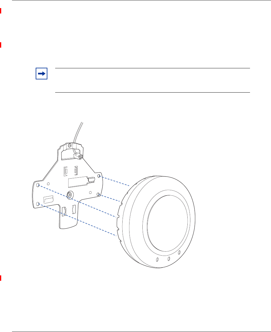
Installing and connecting an 2332 Series 51
Nortel WLAN Access Point 2332 Series Installation Guide
5As shown in Figure 27 on page 51, feed the Cat-5 cable through the port connector opening and align the
universal mounting bracket over the drywall anchors so that the two screw holes in the bracket face the
drywall anchors.
6Insert the #6 sheet metal screws into the screw holes, and tighten them to secure the universal mounting
bracket to the wall or ceiling.
(If you routed the Cat-5 cable through a hole in the wall or ceiling, insert the screw into the center screw
hole only.)
Figure 27. Steps 5 and 6—Bracket Placement on Solid Wall or Ceiling
7As shown in Figure 28, insert the Cat-5 cable into the connector:
Note. Do not insert screws in the four holes on the edges of the bracket. (These
are the holes indicated by the dashed lines in Figure 27.) The AP fits into these
holes. They are not screw holes.
840-9502-0015
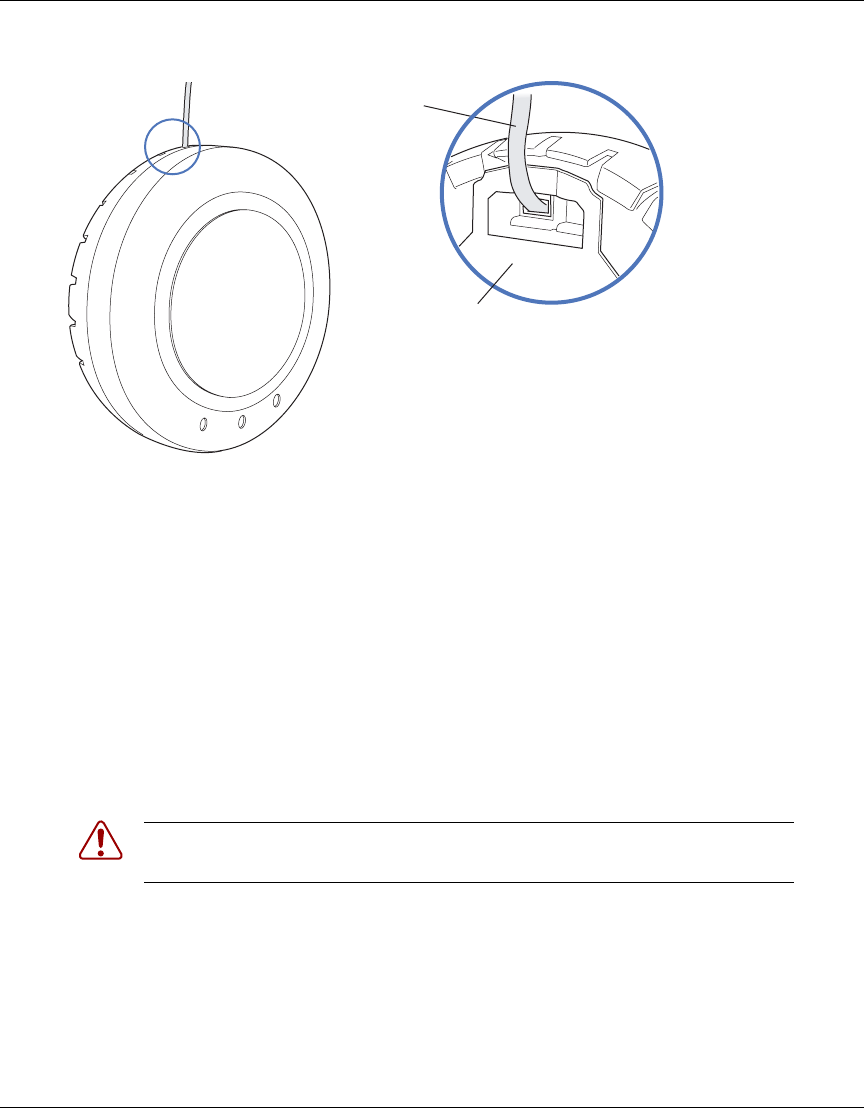
52 Installing and connecting an 2332 Series
NN47250-302 (324136-A Version 01.02)
Figure 28. Step 8—Cable Placement
8Install the Kensington lock (optional).
aLoop the Kensington lock’s cable around an object that cannot be moved or damaged by a person
pulling on the cable.
bInsert the key into the Kensington lock.
cInsert the Kensington lock into the security slot on the AP.
dRotate the key right or left to secure the lock to the AP.
ePull on the lock to verify that it is secured to the AP.
fRemove the key.
9Place the AP on the bracket, making sure to remove any slack that occurs in the cable between the bracket
and the AP.
10 Lock the AP onto the bracket by inserting the 3-mm or 1/8-inch screwdriver into the Lock hole on the
access point as shown in Figure 29.
Warning! To prevent possible damage to the AP, make sure the device is fully
locked onto the bracket before releasing it.
840-9502-0016
Universal mounting bracket
Cable
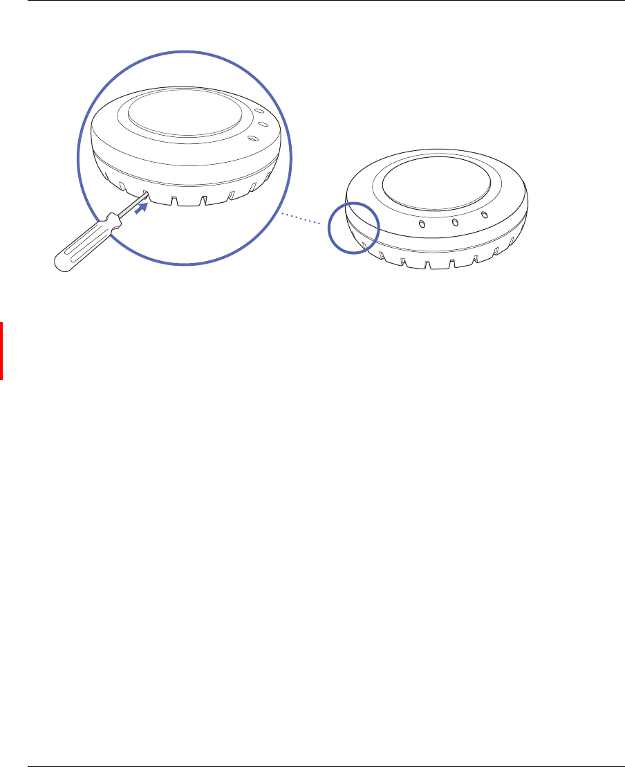
Installing and connecting an 2332 Series 53
Nortel WLAN Access Point 2332 Series Installation Guide
Figure 29. Step 9—Locking the Bracket
11 To ensure that the AP is fully locked onto the bracket, gently pull on the access point and attempt to rotate
it from side to side.
If the access point comes off the bracket, relock the device onto the bracket as described in step 10 on
page 52.
12 If the other end of the Cat-5 cable is not already connected and the link activated, then go to “Connecting
an AP to a WSS” on page 53. Otherwise, go to “Verifying AP health” on page 55.
Connecting an AP to a WSS
You can connect an AP directly to a WSS or indirectly to the switch through an intermediate Layer 2 or Layer 3
network.
• To connect the AP directly to a WSS, configure the WSS port as an AP and use the following procedure to insert the
cable into the WSS and verify the link.
• To connect the AP indirectly to a WSS though the network, configure a Distributed AP connection on the WSS.
You can use the CLI or WLAN Management Software to configure an AP or Distributed AP connection. (See the
Nortel WLAN Security Switch 2300 Series Configuration Guide or the Nortel WLAN Management Software 2300 Series
User Guide.)
840-9502-0062
Lock
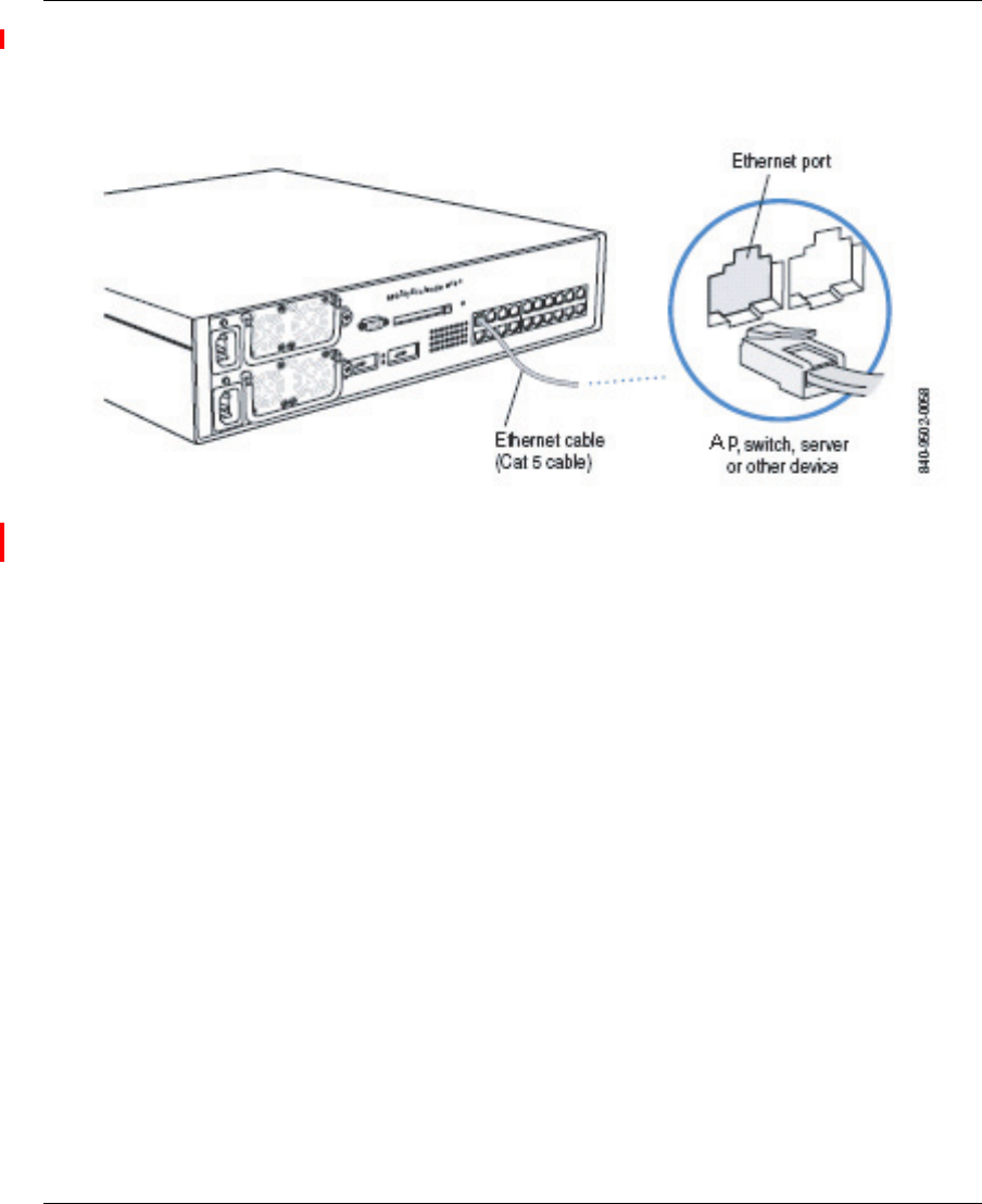
54 Installing and connecting an 2332 Series
NN47250-302 (324136-A Version 01.02)
Figure 30 shows how to insert a Cat-5 cable into a 10/100 Ethernet port on a WSS. Refer to this figure as you perform
the procedure.
Figure 30. 10/100 Cat-5 Cable Installation
1Insert a Cat-5 cable with a standard RJ-45 connector as shown in Figure 30. For connection to an AP, use
the supplied Cat-5 straight-through cable.
2When the link is activated, observe the AP LED for the port on the WSS:
AP LED Appearance Meaning
Solid green For an AP’s active link, all the following are true:
• AP has booted.
• AP has received a valid configuration from the WSS.
• Management link with an AP is operational.
• At least one radio is enabled or is in sentry mode.
For an AP’s secondary link, the link is present.
Alternating green and amber AP is booting with an image received from the WSS. After
the access point boots and receives its configuration, this
LED appearance persists until a radio is enabled or is
placed in sentry mode.
Solid amber PoE is on.
Blinking amber AP is unresponsive or there is a PoE problem.
Unlit PoE is off.

Installing and connecting an 2332 Series 55
Nortel WLAN Access Point 2332 Series Installation Guide
Verifying AP health
After you install the AP and enable PoE on the Ethernet cable connected to the AP, you can easily verify the AP’s status
by observing the LEDs, particularly the health LED. (See Figure 3 on page 29.)
The health or LINK LED indicates whether the AP is ready for operation.
• If the LED is green and glowing steadily, the AP has been booted successfully by the WSS and is ready for
operation.
• If the LED is not steadily glowing green, contact the system administrator for the WSS or, if you are the system
administrator, see Appendix , “AP troubleshooting,” on page 107.
Note. The 10/100 Ethernet ports on a WSS are configured as wired network ports by
default. You or the system administrator must change the port type for a WSS port directly
connected to an AP to activate the link. (See the Nortel WLAN 2300 Series—Security
Switch Installation and Basic Configuration Guide.)

56 Installing and connecting an 2332 Series
NN47250-302 (324136-A Version 01.02)

57
Nortel WLAN Access Point 2332 Series Installation Guide
External Antennas
Operation in the 5.0 GHz bands are limited to the following channels:
• 2332-A1: 36, 40, 44, 48, 149, 153, 157, 161, 165
• 2332-E1: 36, 40, 44, 48
This section introduces the external antenna portfolio available for the WLAN 2300 System 2332 Series.
• The portfolio includes 802.11b/g (2.4 GHz), 802.11a (5.0 GHz) and 802.11a/b/g (2.4/5.0 Hz) models.
• The addition of external antennas to the WLAN 2300 System portfolio improves overall system value:
❥Improved deployment flexibility – Planners can choose an antenna pattern that meets coverage
requirements while allowing for convenient AP placement and installation.
❥Improved coverage and performance – External antennas allow planners to optimize coverage
and deliver higher available data rates to user concentrations.
❥Can provide a low cost fix for trouble spots - Appropriately outfitting existing APs with
external antennas can greatly improve coverage and available data rates in areas that are not
adequately serviced.
❥Increased security – Perimeter access points outfitted with directional external antennas can
focus energy inwards and increase security by preventing signal “leakage” outside the office.
❥Improved aesthetics – External antennas feature a 3 foot cable that allows the connected access
point to be installed out-of-sight.
❥Lower cost of coverage – External antennas improve overall system efficiency by effectively
directing available energy to where it’s needed. This ensures overall system utility is
maximized for any installation.
External antenna selector guide for the 2332 Series for indoor operation . . . . . . . . . . 59
. . . . . . . . . . . . . . . . . . . . . . . . . . . . . . . . . . . . . . . . . . . . . . . . . . . . . . . . . . . . . . . . . . . 60
Dual-Band 802.11a/b/g (2.4/5.0 GHz) . . . . . . . . . . . . . . . . . . . . . . . . . . . . . . . . . . . . . 65
Antenna descriptions – 802.11a (5.0 GHz) antennas . . . . . . . . . . . . . . . . . . . . . . . . . . 66
Antenna descriptions – 802.11b/g (2.4 GHz) antennas . . . . . . . . . . . . . . . . . . . . . . . . 75
2.4/5.0 GHz Dual antenna . . . . . . . . . . . . . . . . . . . . . . . . . . . . . . . . . . . . . . . . . . . . . . 99
Glossary of common antenna terminology . . . . . . . . . . . . . . . . . . . . . . . . . . . . . . . . 106

58 External Antennas
NN47250-307 (324136-A Version 01.02)
The WLAN 2300 series external antennas are the only external antennas certified by Nortel for use with WLAN 2300
systems. WLAN Access Points 2332 Series outfitted with non-certified external antennas are not supported under
Nortel support agreements.
The WLAN 2300 system must be upgraded to WSS Software v4.1 (or later) and WMS v4.1 (or later). This upgrade
includes antenna pattern libraries for the WLAN 2300 series external antenna portfolio and allows the system to:
❥Accurately predict RF environments when using the WMS planning tool to calculate coverage
provided by access points equipped with external antennas.
❥Correctly interpret received signal strength measurements from APs with external antennas when
calculating rogue device or client location.
The WLAN 2300 System external antenna portfolio is sourced from Cushcraft, a world leader in the development of
advanced antenna technology and products.
❥The Cushcraft products have been modified for compatibility with the 2332 Series.
❥Nortel versions are equipped with an R-SMA (reverse SMA) type connector to comply with industry
regulatory quality standards and correctly interface with the 2332 Series.
❥The Cushcraft model numbers presented throughout this bulletin refer to the Nortel specific versions
and may not exactly match similar versions promoted on Cushcraft’s website or other product
materials.
❥Nortel has tested and measured each product. The antenna gains expressed in dBi are the Nortel
tested values and may differ slightly from those published by Cushcraft for similar products.
External Antennas 59
Nortel WLAN Access Point 2332 Series Installation Guide
External antenna selector guide for the 2332 Series for indoor operation
Warning! Intentional radiators, such as the Nortel WLAN Access Point 2332
Series are not intended to be operated with any antenna(s) other than those
furnished by Nortel. An intentional radiator may only be operated with the
antenna(s) with which it is authorized. For a complete listing of antennas for
use with this product, visit
http://www.nortel.com/support.
Note. At this point of time, the below section will not be updated for 2332 Series.

60 External Antennas
NN47250-307 (324136-A Version 01.02)
Table 4: External Antenna Selector Guide for 2332 Series
Cushcraft
Nortel
Model
Number
WSS
Model
String
WLAN 2332 Series 2.4 GHz
Antennas
S2403BHN36RSM DR4000072E6
(Discontinued)
24453 DR4000072E6 has been replaced with the
DR4000088E6. They have the same electrical
characteristics and the DR4000088E6 can now be
mounted on either a pole or hung from a ceiling.
S2403BPXN36RSM DR4000088E6
(Replaces
DR4000072E6)
24493 WLAN Collinear Omni-directional Dipole
Antenna contains two collocated elements with an
average gain of 4.9 dBi and a 3-foot cable with a
Reverse SMA connector. For use in Warehouses,
Auditoriums, Shopping Malls, industrial
complexes and more. It can be mounted either on a
pole or hung from a ceiling.
S2406PN36RSM DR4000075E6 24553 WLAN Directional Patch Panel Antenna with an
average gain of 6.5 dBi and a 3-foot cable with a
Reverse SMA connector. For use in Hallways or
corridors. Easy to disguise or hide.
SL2402PN36RSM DR4000074E6 24203 WLAN Omni-directional Patch Panel Ceiling
Mount Antenna with an average gain of 0.0 dBi
and a 3-foot cable with a Reverse SMA connector.
For use in contemporary in-building WLAN
applications.
SQ2405DDN36RSM DR4000073E6 24403 WLAN Bi-directional Patch Panel Ceiling Mount
Antenna with an average gain of 4.5 dBi and a
3-foot cable with a Reverse SMA connector. For
use in Offices, Shopping Complexes,
Transportation Terminals, Educational Campuses,
Hallways, and Tunnels.
S2409PN36RSM DR4000076E6 24883 WLAN Directional Patch Panel Array Antenna
with an average gain of 8.8 dBi and a 3-foot cable
with a Reverse SMA connector. For use where a
shaped pattern is needed to provide enhanced
coverage of deep rooms, warehouse bays, or any
elongated activity zone
PC2415NA36RSM DR4000077E6 24143 WLAN 15-Element Yagi Antenna with an average
gain of 14.1 dBi, 3-foot cable with a Reverse SMA
connector and an articulating mount. Antenna is
rugged, easy to install and provides a very
symmetrical and uniform pattern. Designed for
long, narrow coverage environments, like a tunnel.

External Antennas 61
Nortel WLAN Access Point 2332 Series Installation Guide
SR24120DN36RSM DR4000087E6 24113 WLAN Directional Patch Panel Array Antenna
with an average gain of 11 dBi, 3-foot cable with a
Reverse SMA connector and either a tilt, wall or
pole mounting capability. Antenna is rugged, easy
to install and provides a very symmetrical uniform
120 degree H-plane and 14 degree E-plane pattern.
Designed for long, wide coverage environments.
S241290PN36RSM DR4000086E6 24123 WLAN Directional Patch Panel Array Antenna
with an average gain of 12 dBi, 3-foot cable with a
Reverse SMA connector and either a tilt, wall or
pole mounting capability. Antenna is rugged, easy
to install and provides a very symmetrical and
uniform 90 degree H-plane and 17 degree E-plane
pattern. Designed for long, wide coverage
environments.
Cushcraft
Nortel
Model
Number
WSS
Model
String
WLAN 2332 Series 5.0 GHz
Antennas
SQ5153WPN36RSM DR4000069E6 5303 WLAN Squint Ceiling Mount Omni-directional
Monopole Antenna with an average gain of 3.2 dBi
from 5.15 - 5.25 GHz, 2.5 dBi from
5.25 - 5.35 GHz, 1.6 dBi from 5.470 - 5.725 GHz
and 0.1 dBi from 5.725 - 5.85 GHz. It has a 3-foot
cable with a Reverse SMA connector. For use in
large indoor spaces, locations with high ceilings,
and where extending coverage is needed.
S5153WBPN36RSM DR4000070E6 5643 WLAN Collinear Omni-directional Dipole
Antenna that contains two collocated elements. It
has an average gain of 4.5 dBi from
5.15 - 5.25 GHz, 3.8 dBi from 5.25 - 5.35 GHz,
4.7 dBi from 5.47 -5.725 GHz and 4.4 dBi from
5.725 - 5.85 GHz. It is 7" in height, and has a
3-foot cable with a Reverse SMA connector. For
use in Warehouses, Auditoriums, Shopping Malls,
industrial complexes and other locations.
S51514WPN36RSM DR4000071E6 5133 WLAN Directional Patch Panel Antenna with an
average gain of 13.1 dBi from 5.15 - 5.25 GHz,
13.0 dBi from 5.25 - 5.35 GHz, 13.0 dBi from
5.470 - 5.725 GHz and 12.9 dBi from
5.725 - 5.85 GHz. It has a 3-foot cable with a
Reverse SMA connector. For use in campus or
in-building applications. It offers a very precise
and controllable pattern. Must order mounting
bracket separately.

62 External Antennas
NN47250-307 (324136-A Version 01.02)
WLAN 2332 Series 2.4/5.0 GHz Dual
Antennas
S24493DSN36RSM DR4000078E6 Mixed WLAN Dual-Band, Tri-Mode 802.11 a/b/g Spatial
Diversity Monopole Antenna. It operates over the
2.4 - 2.5 GHz and 4.90 - 5.875 GHz bands. It has
an average gain of 3.0 dBi from 2.4 - 2.5 GHz,
4.0 dBi from 4.90 - 5.15 GHz, 3.9 dBi from
5.15 - 5.25 GHz, 3.2 dBi from 5.25 - 5.35 GHz,
2.9 dBi from 5.470 - 5.725 GHz and 2.6 dBi from
5.725 - 5.85 GHz. It is equipped with a 3-foot cable
and a Reverse SMA connector. Each antenna port
can be used individually to support 802.11 b/g and
802.11a systems simultaneously for dual-band,
non-diversity applications. Optimal for use in high
data rate, high capacity configurations such as
enterprise offices.

External Antennas 63
Nortel WLAN Access Point 2332 Series Installation Guide
Antenna selection decision trees
The following decision trees are intended to quickly guide users to the appropriate model(s) based on basic criteria.
• The distinction between office and industrial types refers solely to the aesthetic suitability of an antenna for each
environment. Any antenna identified as suitable for office deployments can be deployed in industrial environments
and vice versa.
• The Antenna # can be used to quickly identify the appropriate corresponding model in the Antenna Descriptions
section.
• Only one model of dual-band antenna is available for 802.11a/b/g installations - a Dual-band, Tri-mode
802.11a/b/g Spatial Diversity Antenna, model #: DR4000078E6. This unit has a 2.4 GHz and 5 GHz antenna
built-in. It is designed to connect to each of the external ports on the AP. It can be used with only one port
connected, so it could be used in either b/g or a mode in a stand alone application For more information see
“Dual-band, Tri-mode 802.11a/b/g Spatial Diversity Antenna” in the Antenna Descriptions section.
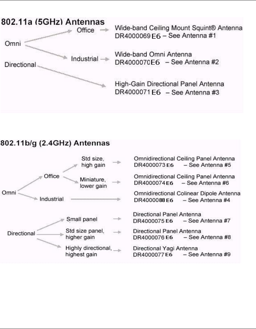
64 External Antennas
NN47250-307 (324136-A Version 01.02)
Figure 31. 5 GHz Antennas
Figure 32. 2.4 GHz Antennas

External Antennas 65
Nortel WLAN Access Point 2332 Series Installation Guide
Dual-Band 802.11a/b/g (2.4/5.0 GHz)
• Dual-band, Tri-mode 802.11a/b/g Spatial Diversity Antenna, DR4000078E6 – See “Dual-band, Tri-mode 802.11a/
b/g Spatial Diversity Antenna”
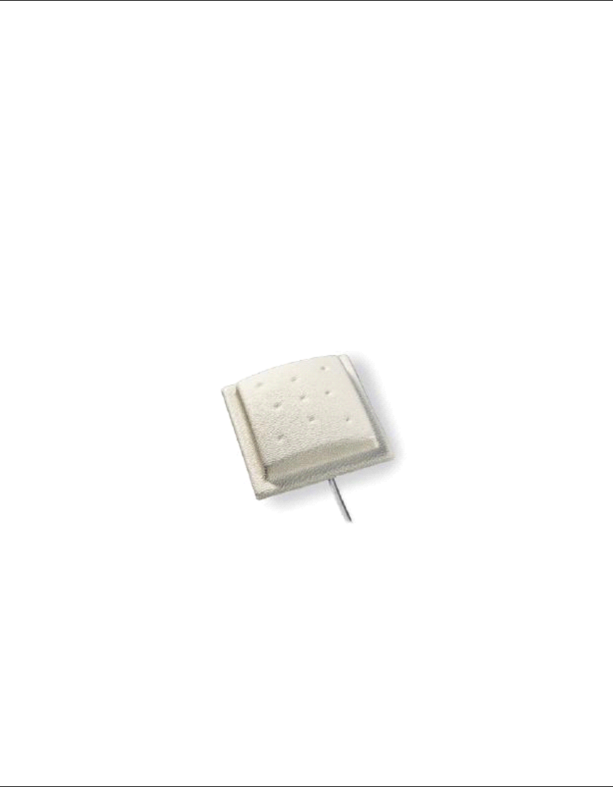
66 External Antennas
NN47250-307 (324136-A Version 01.02)
Antenna descriptions – 802.11a (5.0 GHz) antennas
1Wide-band Ceiling Mount Squint® Antenna
Nortel Order Number: DR4000069E6
❥Cushcraft Model SQ5153WPN36RSM
❥5.15 - 5.25 GHz, 3.2 dBi Peak Gain
5.25 - 5.35 GHz, 2.5 dBi Peak Gain
5.470 - 5.725 GHz, 1.6 dBi Peak Gain
5.725 - 5.85 GHz, 0.1 dBi Peak Gain
❥Ultra-compact, low profile design with minimum visual impact
❥Ideal for large indoor open spaces and locations with high ceilings
❥Measures 2” x 2” x ¾”
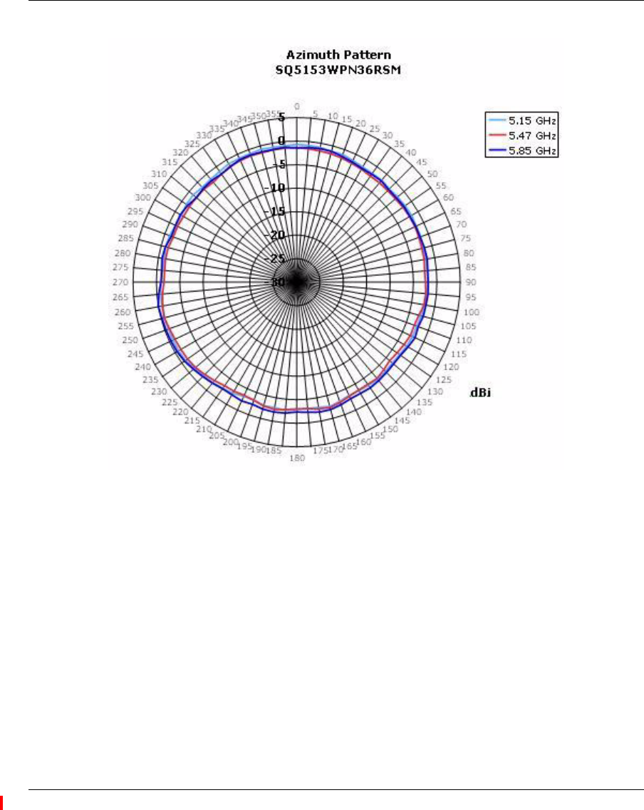
External Antennas 67
Nortel WLAN Access Point 2332 Series Installation Guide
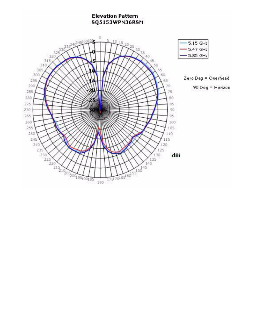
68 External Antennas
NN47250-307 (324136-A Version 01.02)
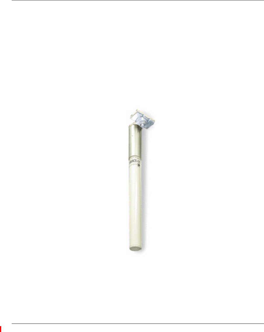
External Antennas 69
Nortel WLAN Access Point 2332 Series Installation Guide
2Wide-band Omni Antenna
Nortel Order Number: DR4000070E6
❥Cushcraft Model S5153WBPN36RSM
❥5.15 - 5.25 GHz, 4.5 dBi Peak Gain
5.25 - 5.35 GHz, 3.8 dBi Peak Gain
5.470 - 5.725 GHz, 4.7 dBi Peak Gain
5.725 - 5.85 GHz, 4.4 dBi Peak Gain
❥Rugged design suitable for industrial environments
❥Ceiling, I-beam and mast mounting options
❥Suitable for large indoor open spaces and locations with high ceilings
❥Slim aspect measuring 11.5” x 1”
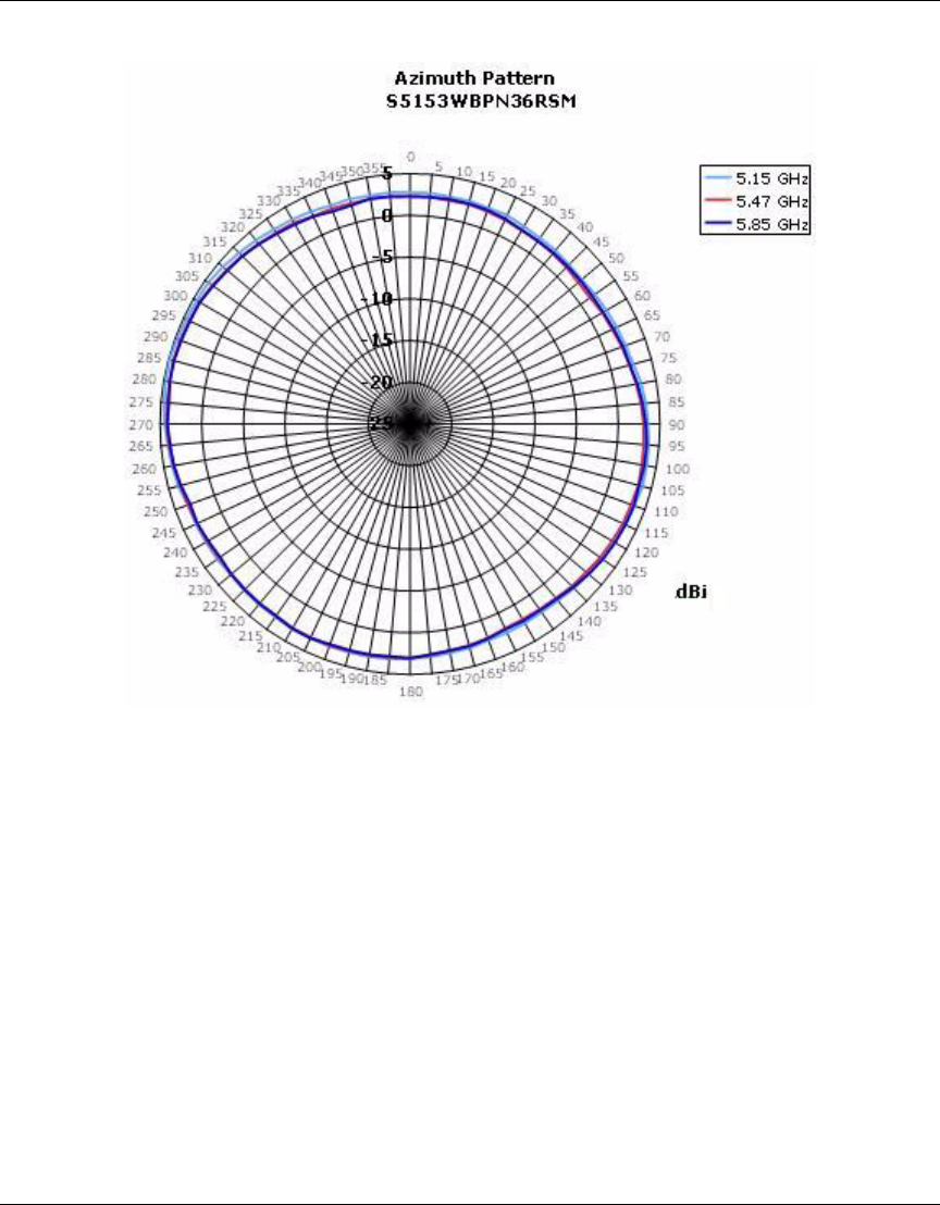
70 External Antennas
NN47250-307 (324136-A Version 01.02)
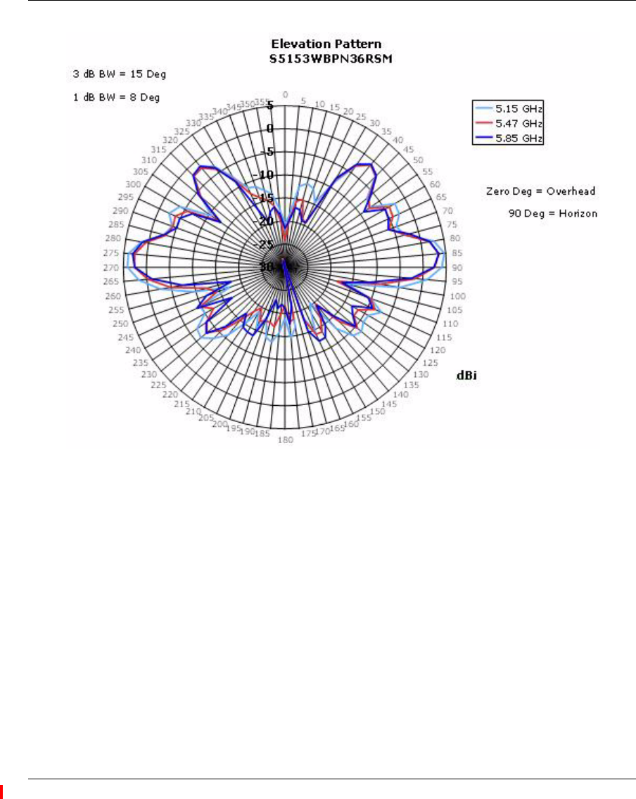
External Antennas 71
Nortel WLAN Access Point 2332 Series Installation Guide
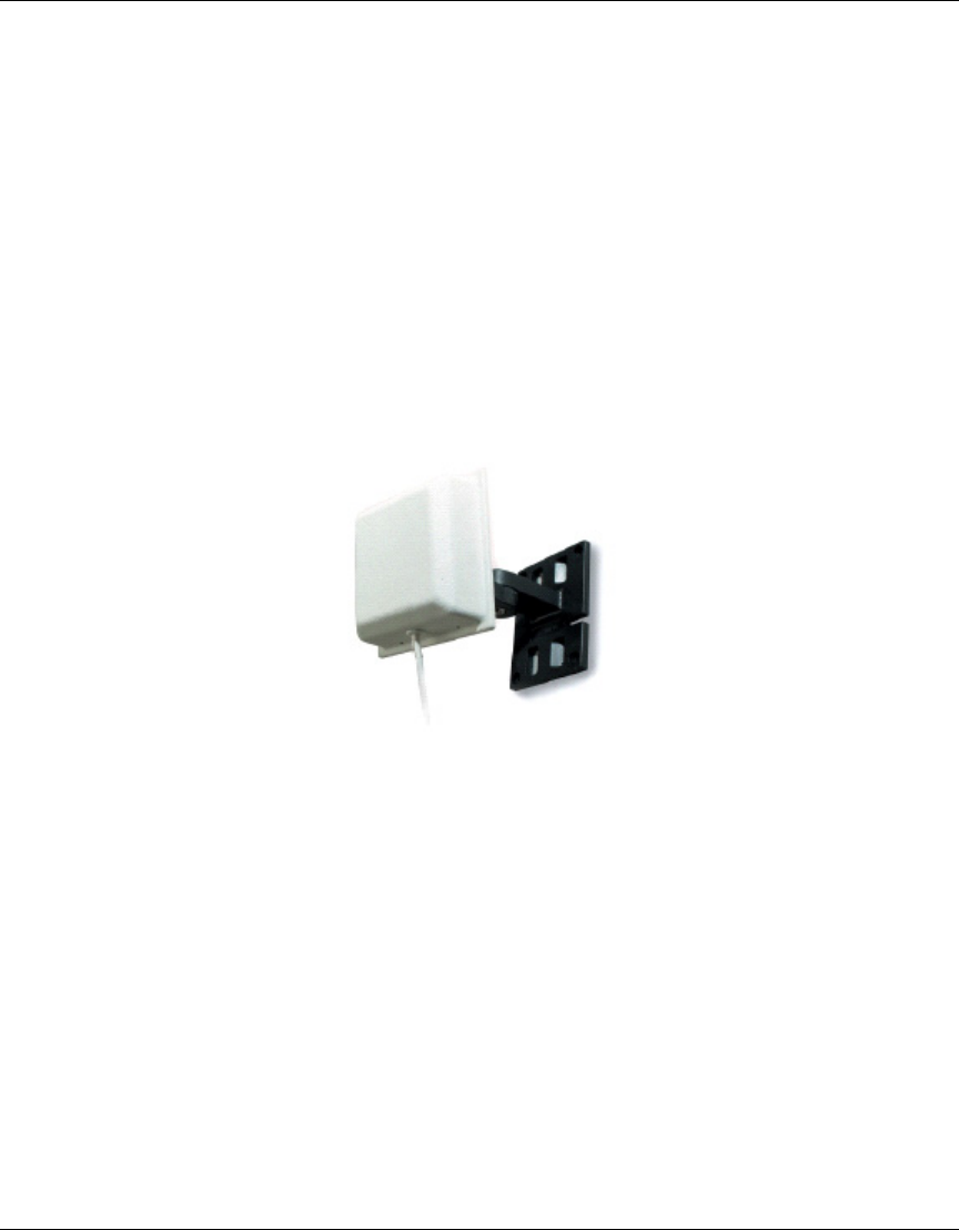
72 External Antennas
NN47250-307 (324136-A Version 01.02)
3High-Gain Directional Panel Antenna
Nortel Order Number: DR4000071E6
❥Cushcraft Model S51514WPN36RSM
❥5.15 - 5.25 GHz, 13.1 dBi
5.25 - 5.35 GHz, 13.0 dBi Peak Gain
5.470 - 5.725 GHz, 13.0 dBi Peak Gain
5.725 - 5.85 GHz, 12.9 dBi Peak Gain
❥Wall or pole mounting
❥Articulating feature allows customizable antenna pattern
❥Measures 4” x 4” x 1.4”
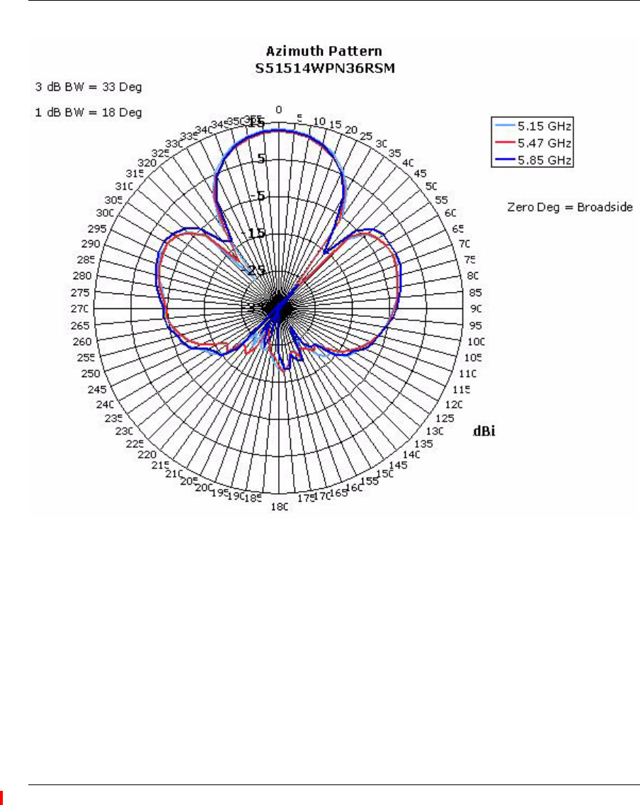
External Antennas 73
Nortel WLAN Access Point 2332 Series Installation Guide
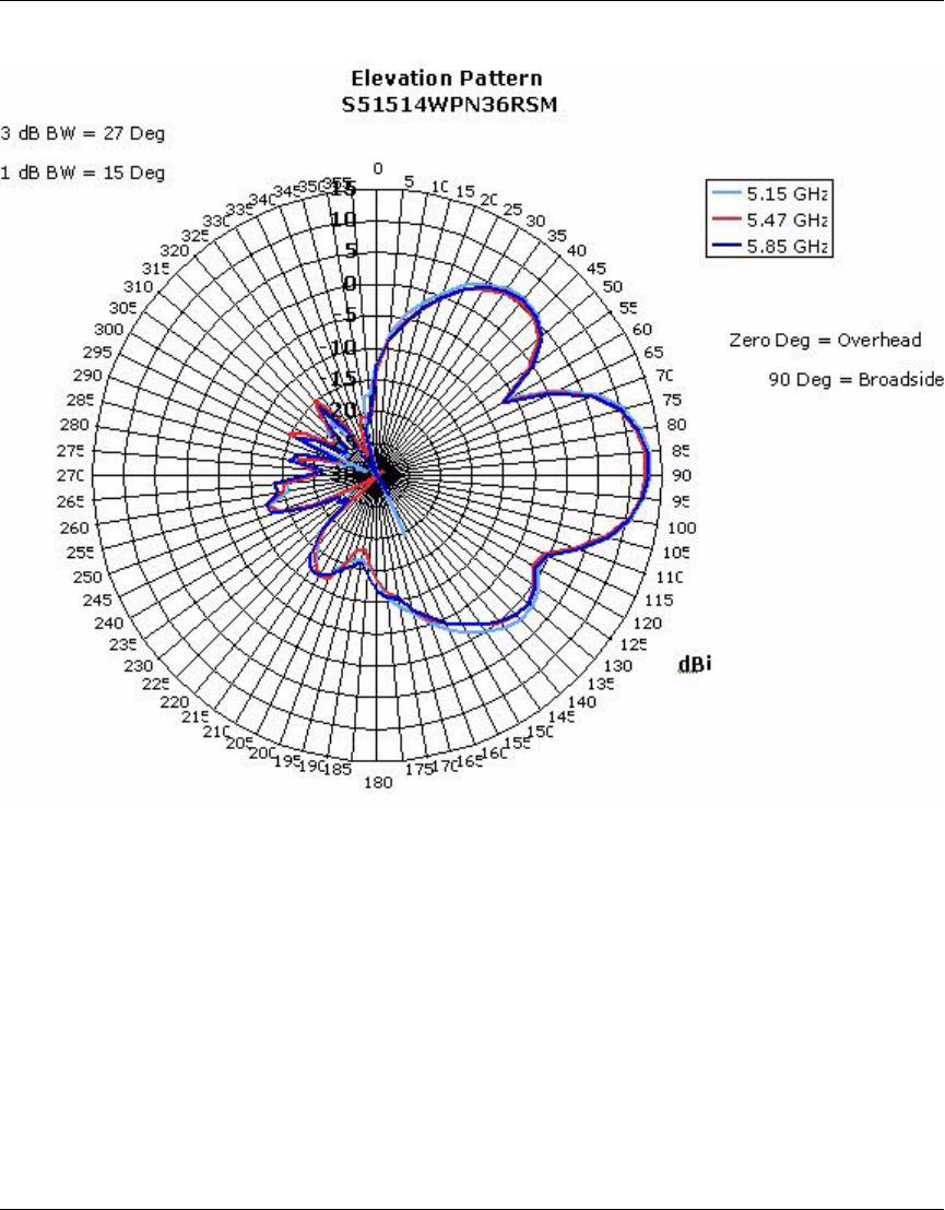
74 External Antennas
NN47250-307 (324136-A Version 01.02)
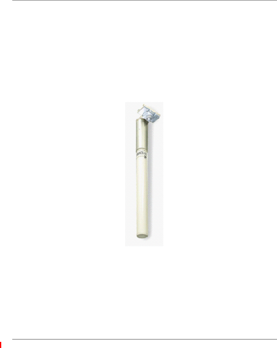
External Antennas 75
Nortel WLAN Access Point 2332 Series Installation Guide
Antenna descriptions – 802.11b/g (2.4 GHz) antennas
4Omni-directional Colinear Dipole Antenna
Nortel Order Number: DR4000088E6 (replaces DR4000072E6)
❥Cushcraft Model S2403BPXN36RSM (replaces S2403BHN36RSM)
❥2.4 - 2.5 GHz, 4.9 dBi Peak Gain
❥Rugged housing suitable for industrial deployments
❥Ideal for large open areas
❥Suspended ceiling mount
❥Measures 11.5” x 1”
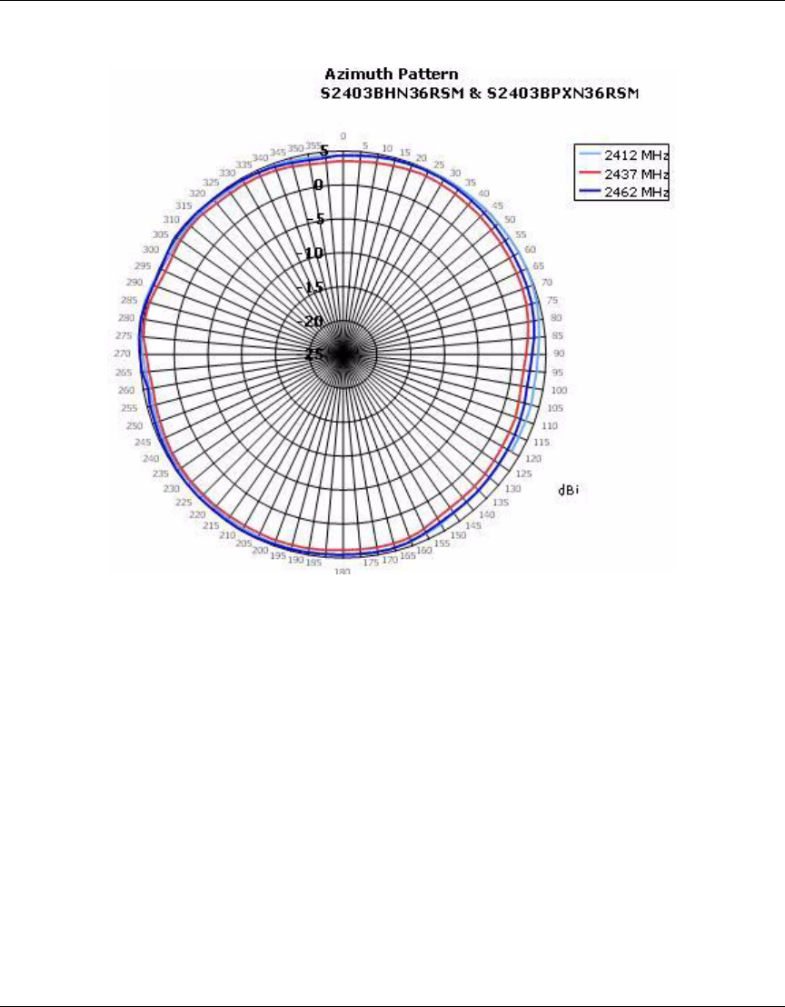
76 External Antennas
NN47250-307 (324136-A Version 01.02)
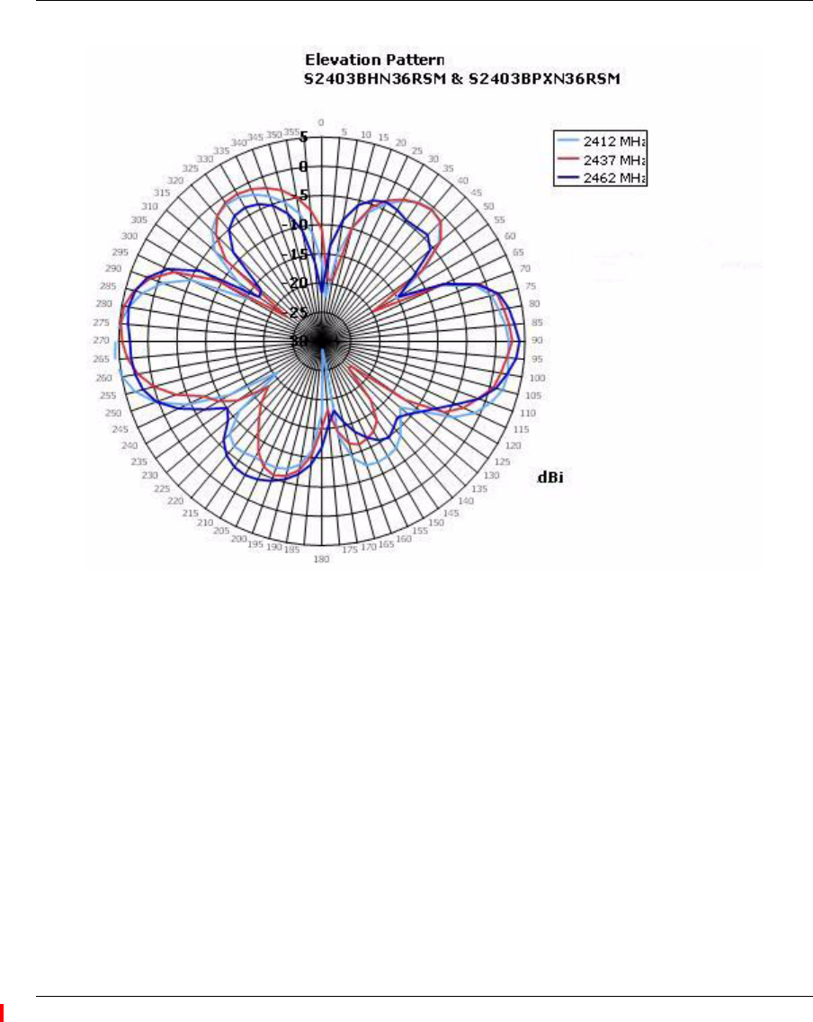
External Antennas 77
Nortel WLAN Access Point 2332 Series Installation Guide
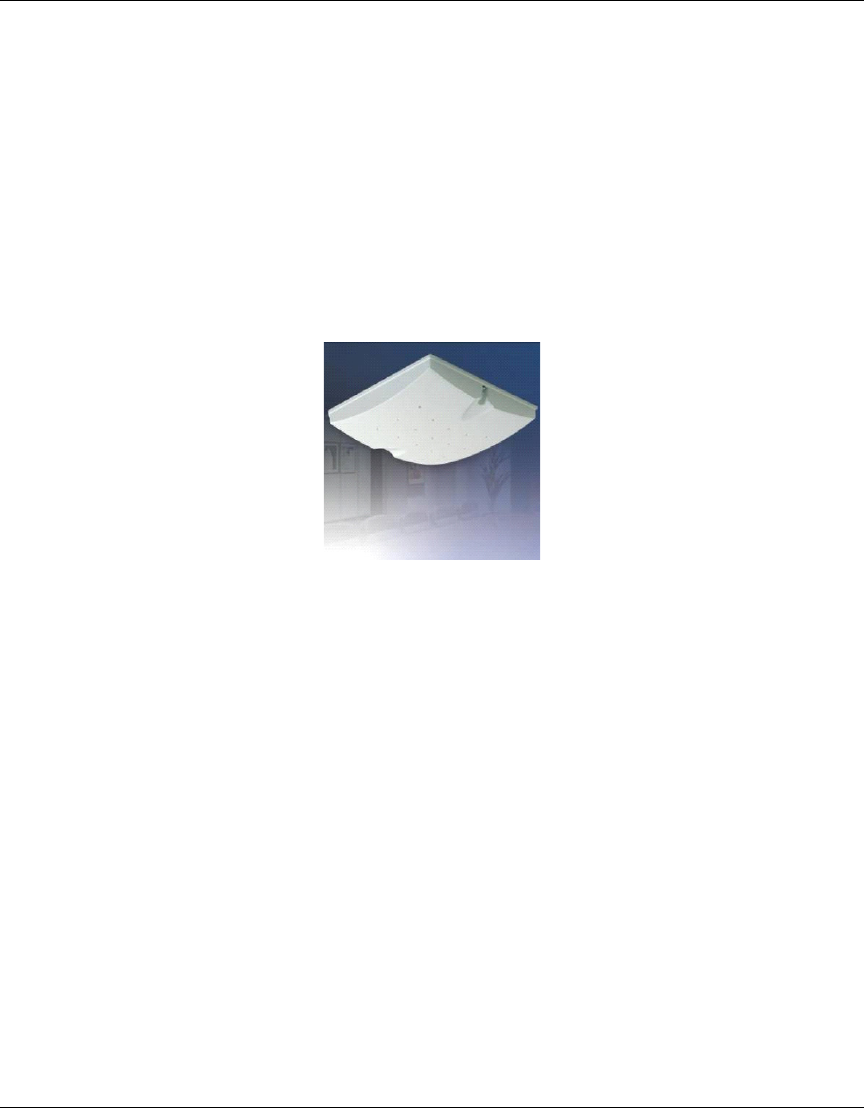
78 External Antennas
NN47250-307 (324136-A Version 01.02)
5Omni-directional Ceiling Panel Antenna
Nortel Order Number: DR4000073E6
❥Cushcraft Model SQ2405DDN36RSM
❥2.4 - 2.5 GHz, 4.5 dBi Peak Gain
❥Bi-directional, low profile ceiling antenna
❥Paintable with light, non-metallic coating for custom color matching
❥3-foot cable
❥Measures 6.12” x 6.12” x 1.25”
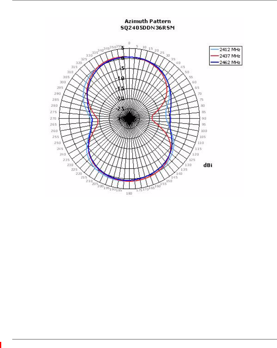
External Antennas 79
Nortel WLAN Access Point 2332 Series Installation Guide
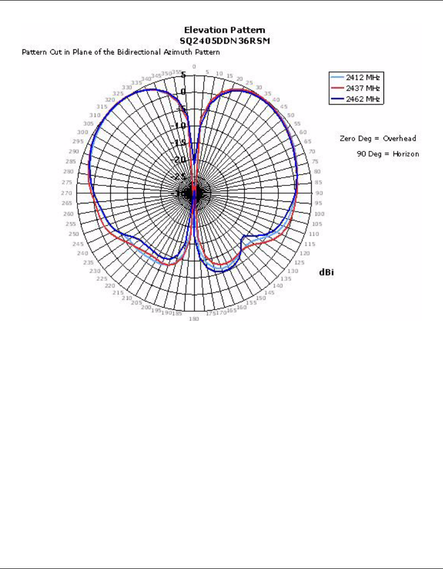
80 External Antennas
NN47250-307 (324136-A Version 01.02)
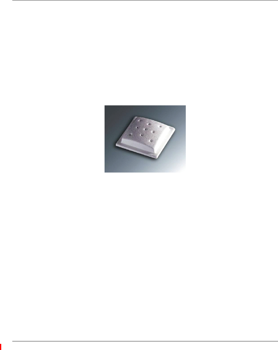
External Antennas 81
Nortel WLAN Access Point 2332 Series Installation Guide
6Omni-directional Ceiling Panel Antenna
Nortel Order Number: DR4000074E6
❥Cushcraft Model SL2402PN36RSM
❥2.4 - 2.5 GHz, 0.0 dBi Peak Gain
❥Very uniform and symmetrical antenna pattern
❥Well-suited for high-density deployments
❥3-foot cable
❥Measures only 2” x 2” x 0.7”
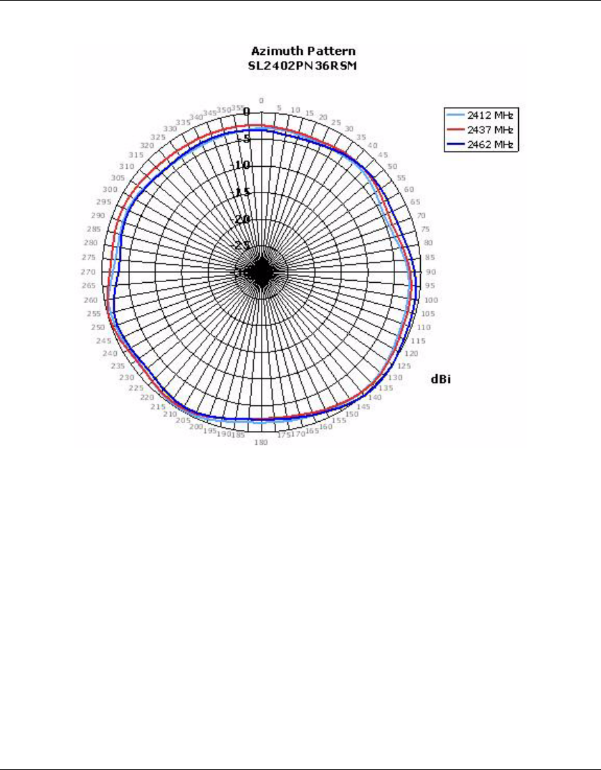
82 External Antennas
NN47250-307 (324136-A Version 01.02)
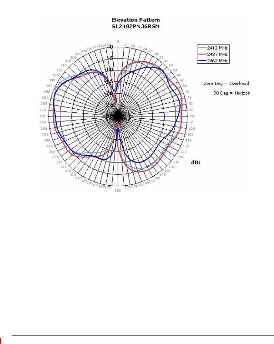
External Antennas 83
Nortel WLAN Access Point 2332 Series Installation Guide
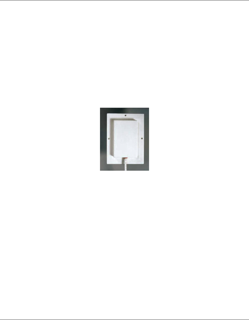
84 External Antennas
NN47250-307 (324136-A Version 01.02)
7Directional Panel Antenna
Nortel Order Number: DR4000075E6
❥Cushcraft Model S2406PN36RSM
❥2.4 - 2.5 GHz, 6.5 dBi Peak Gain
❥Well-suited for wall mounted applications
❥Good for hallways and corridors
❥Easy to disguise or hide
❥3-foot cable
❥Measures only 5.2” x 3.8” x 0.5”
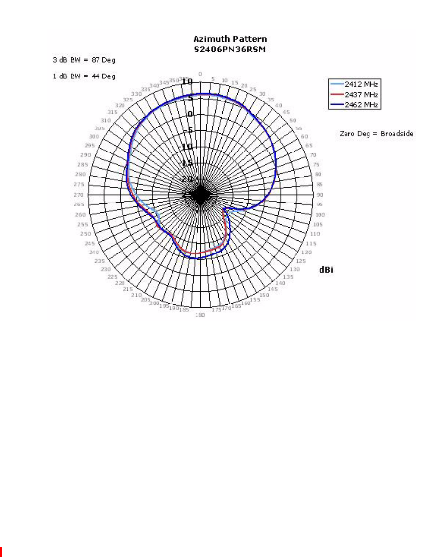
External Antennas 85
Nortel WLAN Access Point 2332 Series Installation Guide
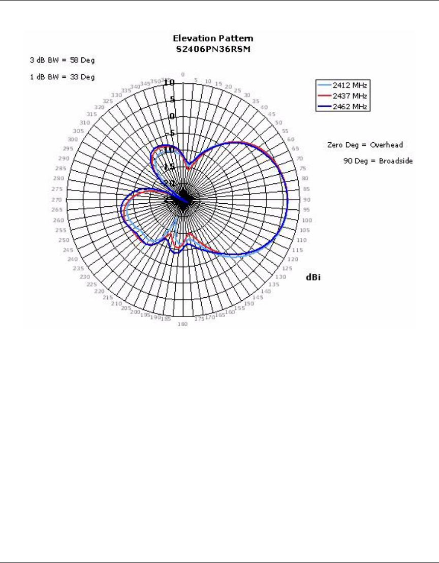
86 External Antennas
NN47250-307 (324136-A Version 01.02)
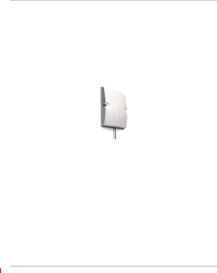
External Antennas 87
Nortel WLAN Access Point 2332 Series Installation Guide
8Directional Panel Antenna
Nortel Order Number: DR4000076E6
❥Cushcraft Model S2409PN36RSM
❥2.4 - 2.5 GHz, 8.8 dBi Peak Gain
❥Well-suited for wall mounted applications
❥Good for hallways and corridors where multi-path and scattering can be a problem
❥3-foot cable
❥Measures only 6” x 6” x 1.25”
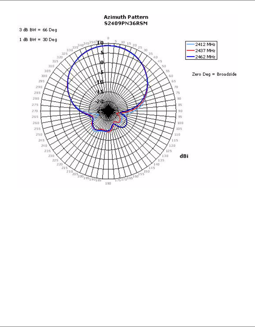
88 External Antennas
NN47250-307 (324136-A Version 01.02)
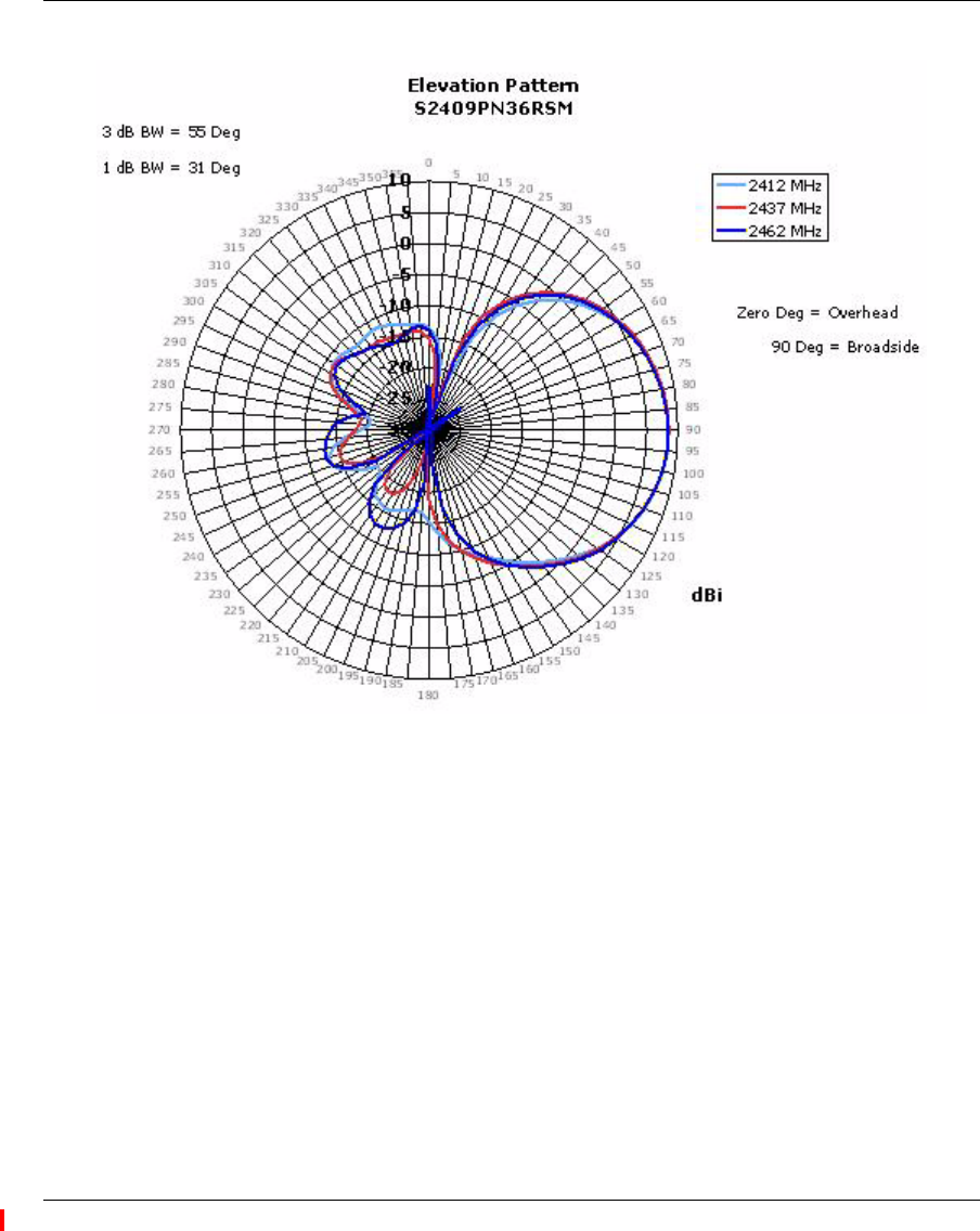
External Antennas 89
Nortel WLAN Access Point 2332 Series Installation Guide