Nortel Networks 2332 802.11 A/B/G Access Point User Manual 2
Nortel Networks, Inc. 802.11 A/B/G Access Point Users Manual 2
Contents
- 1. User Manual
- 2. Users Manual 2
- 3. User Manual 1
Users Manual 2
90 External Antennas
NN47250-307 (324136-A Version 01.02)
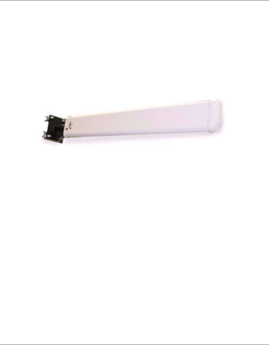
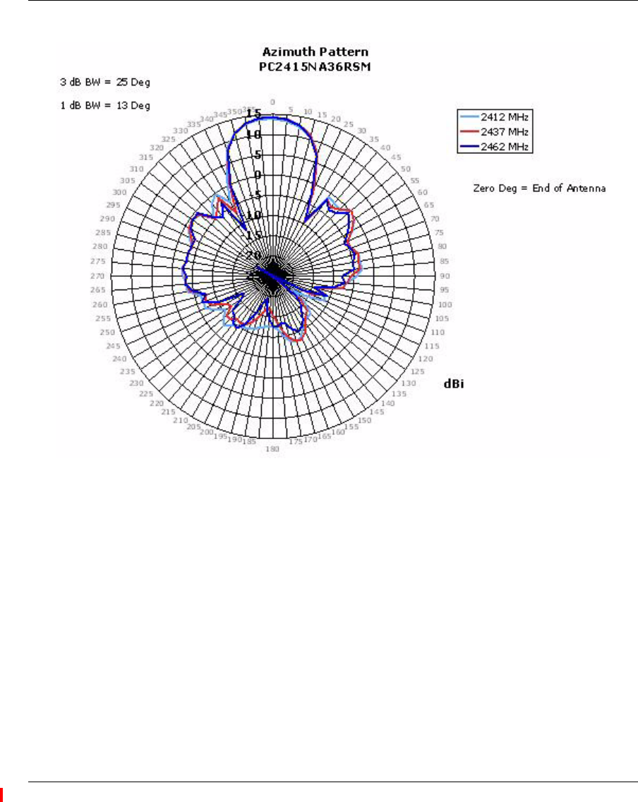
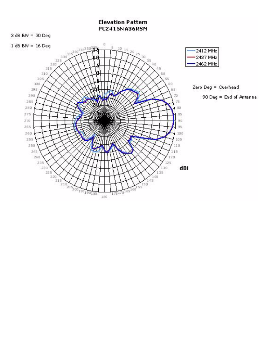
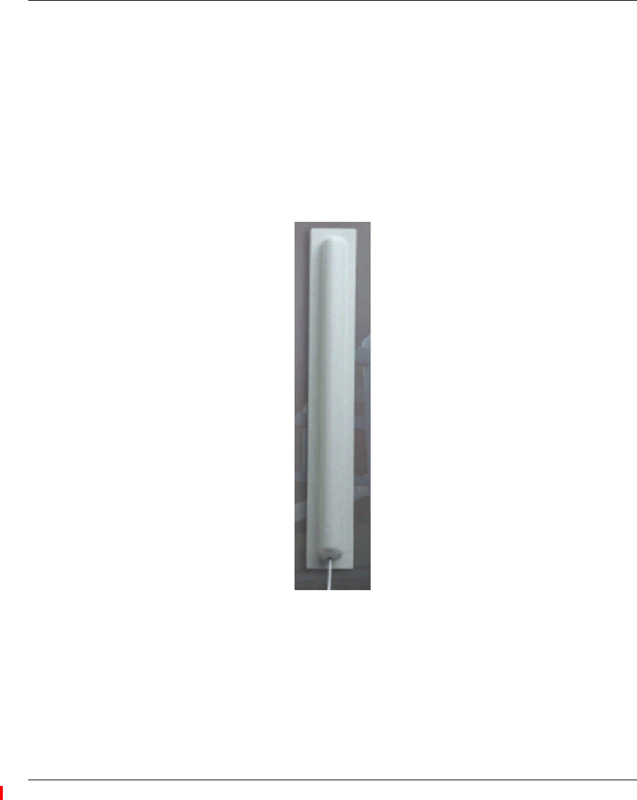
9Directional Yagi Antenna
Nortel Order Number: DR4000077E6
❥Cushcraft Model PC2415NA36RSM
❥2.4 - 2.5 GHz, 14.1 dBi Peak Gain
❥Articulating mount for precise direction pointing
❥Good for long and narrow zones like tunnels
❥3-foot cable
❥Measures 26.5” x 3.75” x 1.5”
External Antennas 91
Nortel WLAN Access Point 2332 Series Installation Guide
92 External Antennas
NN47250-307 (324136-A Version 01.02)
External Antennas 93
Nortel WLAN Access Point 2332 Series Installation Guide
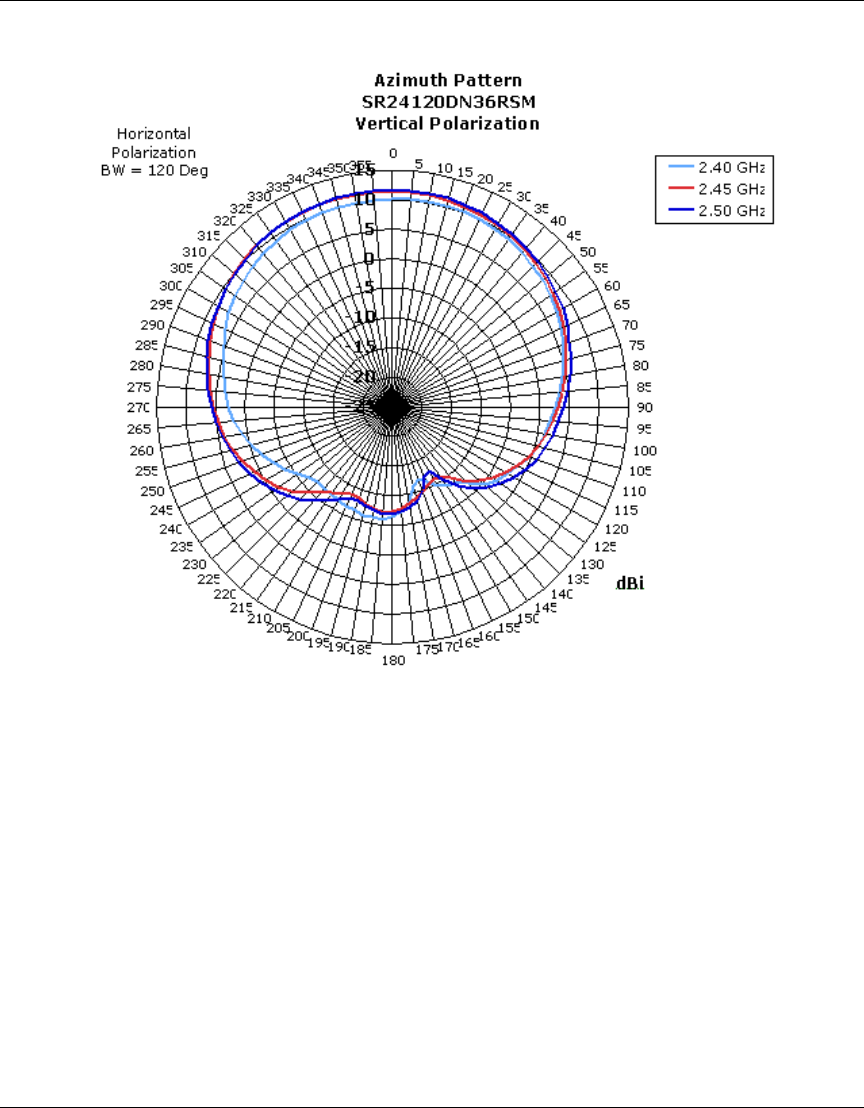
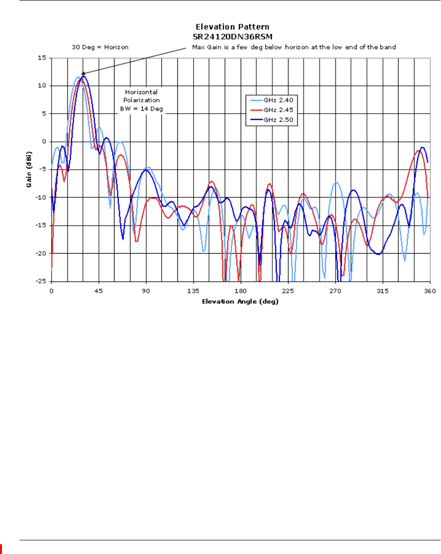
10 Directional Patch Panel Antenna
Nortel Order Number: DR4000087E6
❥Cushcraft Model SR24120DN36RSM
❥2.4 - 2.5 GHz, 11 dBi Peak Gain
❥Uniform 120 degree H-plane and 14 degree E-plane pattern
❥Tilt-mount available for precise direction pointing
❥Designed for long, wide coverage environments
❥3-foot cable
❥Measures 23" x 3" x 2"
94 External Antennas
NN47250-307 (324136-A Version 01.02)
External Antennas 95
Nortel WLAN Access Point 2332 Series Installation Guide
96 External Antennas
NN47250-307 (324136-A Version 01.02)
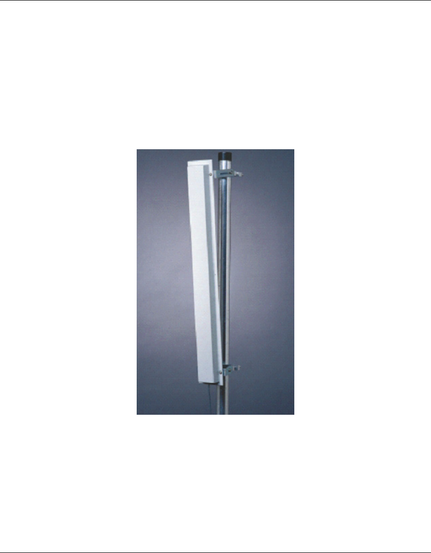
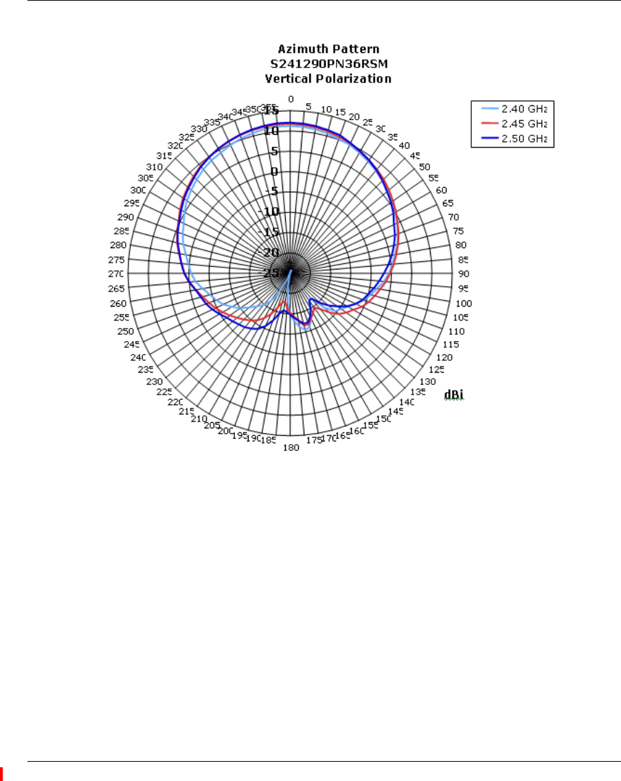
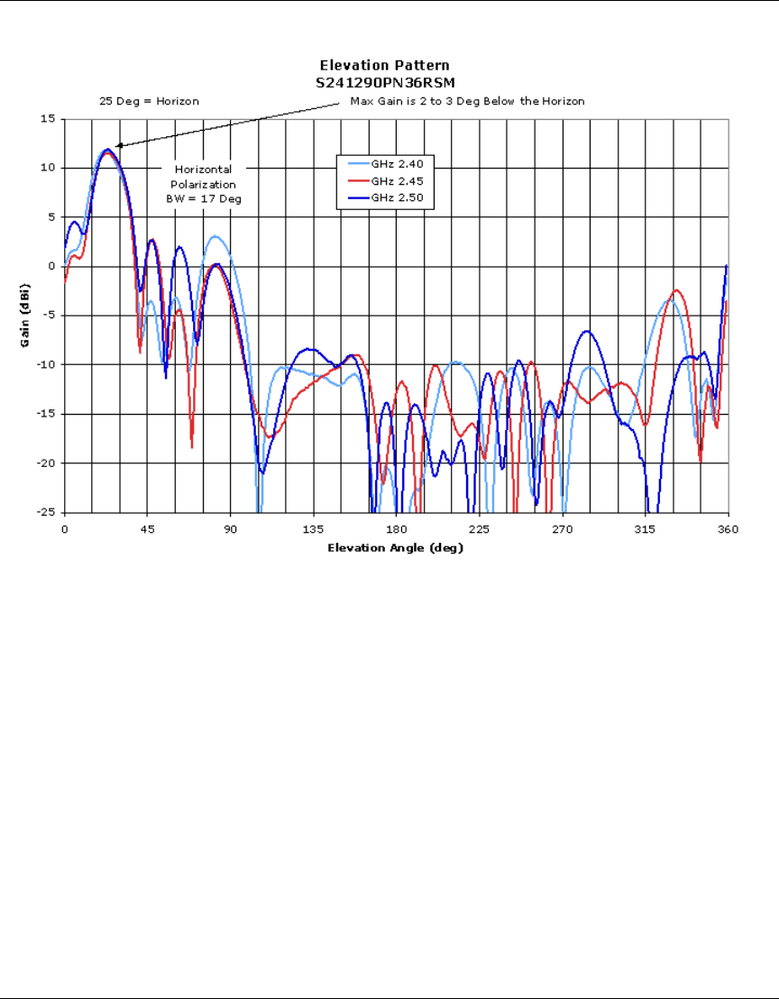
11 Directional Patch Panel Antenna
Nortel Order Number: DR4000086E6
❥Cushcraft Model S241290PN36RSM
❥2.4 - 2.5 GHz, 12 dBi Peak Gain
❥Uniform 90 degree H-plane and 17 degree E-plane pattern
❥Tilt-mount available for precise direction pointing(shown)
❥Designed for long, wide coverage environments
❥3-foot cable
❥Measures 26" x 3" x 1"
External Antennas 97
Nortel WLAN Access Point 2332 Series Installation Guide
Horizontal
Polarization
BW = 90 Deg
98 External Antennas
NN47250-307 (324136-A Version 01.02)
External Antennas 99
Nortel WLAN Access Point 2332 Series Installation Guide
2.4/5.0 GHz Dual antenna
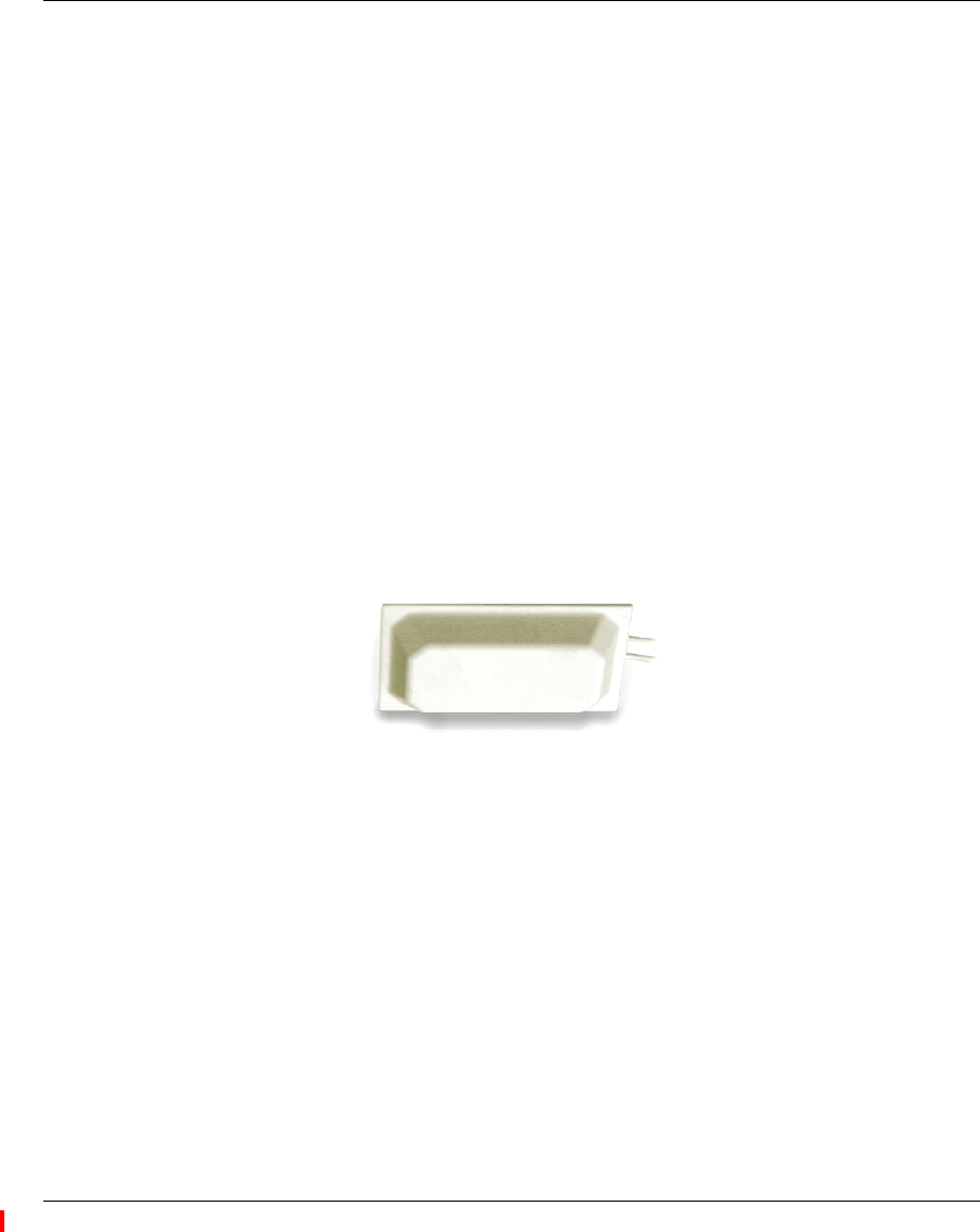
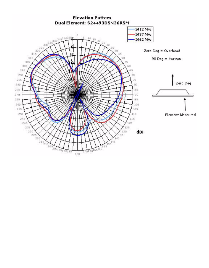
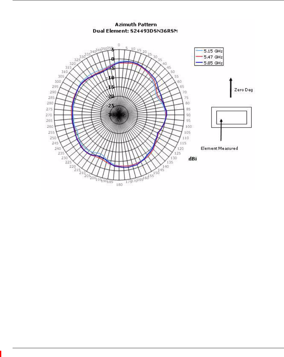
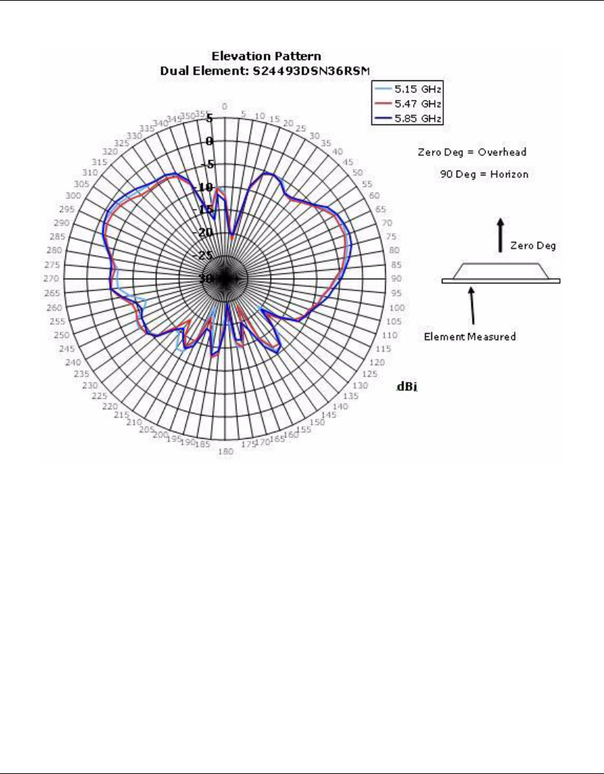
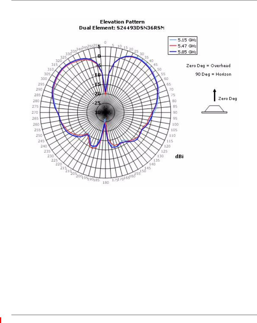
12 Dual-band, Tri-mode 802.11a/b/g Spatial Diversity Antenna
Nortel Order Number: DR4000078E6
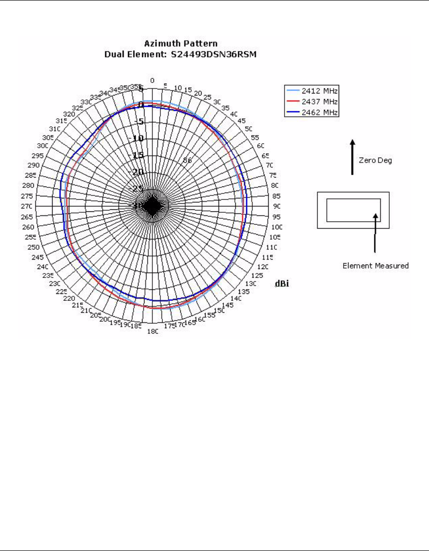
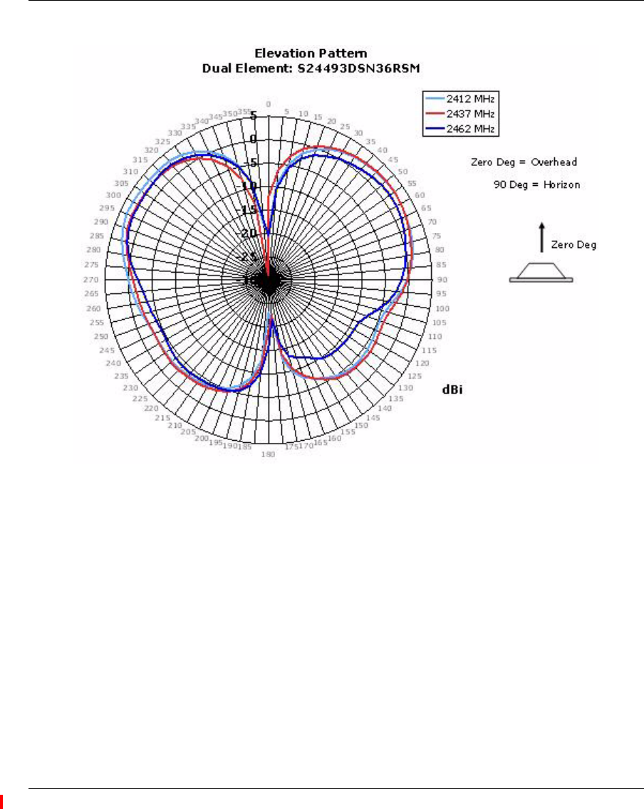
❥Cushcraft Model S24493DSN36RSM
❥2.4 - 2.5 GHz, 3.0 dBi Peak Gain
❥4.90 - 5.15 GHz, 4.0 dBi Peak Gain
❥5.15 - 5.25 GHz, 3.9 dBi Peak Gain
5.25 - 5.35 GHz, 3.2 dBi Peak Gain
5.470 - 5.725 GHz, 2.9 dBi Peak Gain
5.725 - 5.85 GHz, 2.6 dBi Peak Gain
❥Each antenna port can be used individually for simultaneous 802.11a and 802.11b/g
❥Well-suited for high data rate office applications
❥3-foot cable
❥Measures 6.16” x .89” x 3.66”
100 External Antennas
NN47250-307 (324136-A Version 01.02)
Azimuth Pattern for 2.4 GHz
External Antennas 101
Nortel WLAN Access Point 2332 Series Installation Guide
Elevation Pattern 1 for 2.4 GHz
102 External Antennas
NN47250-307 (324136-A Version 01.02)
Elevation Pattern 2 for 2.4 GHz
External Antennas 103
Nortel WLAN Access Point 2332 Series Installation Guide
Azimuth Pattern for 5.0 GHz
104 External Antennas
NN47250-307 (324136-A Version 01.02)
Elevation Pattern 1 for 5.0 GHz
External Antennas 105
Nortel WLAN Access Point 2332 Series Installation Guide
Elevation Pattern 2 for 5.0 GHz

106 External Antennas
NN47250-307 (324136-A Version 01.02)
Glossary of common antenna terminology
The following glossary includes basic antenna terminology that can help in the selection and/or recommendation of a
particular antenna. These terms are used throughout the remainder of the document:
Omnidirectional (Omni) – Refers to the antenna coverage pattern. An omnidirectional antenna creates a uniform
coverage pattern. Most omnidirectional antennas are weakest directly above and directly below their endpoints – this
characteristic creates the familiar dual-lobe pattern shown on the E-plane graphs. Nulls are typically related to the orien-
tation of the dipole/monopole antenna relative to the horizontal or vertical planes. The lobes grow and shrink depending
upon the ground plane effects and cancellation/addition of the radiating signal. Omnidirectional antennas are suitable for
most general deployments.
Directional – Refers to the antenna coverage pattern. A directional antenna focuses its lobe or radiated energy in a
particular direction. In general, as the gain of a directional antenna increases, the radiating beamwidth or lobe decreases.
This design increases the transmitted power and communication distance in a specific direction at the expense of
uniform coverage, as compared to an omnidirectional antenna. A directional antenna must be “aimed” at the intended
coverage zone.
Gain – Expressed in dBi, indicates the relative increase in radiated power over an isotropic point radiating source with a
reference gain of 1.0.
Each 3 dB increment in power effectively doubles the radiated energy. For example, an antenna with a gain of 9 dBi
increases the transmit power 8 times more than an isotropic point radiating source. For example:
12.5 mW = 11 dBm
11 dBm + 9dBi = 20 dBm
20 dBm = 100 mW
100mw/12.5 mW = 8 times more power
E-Plane graph – The elevation plane graph shows the radiated antenna coverage pattern as a vertical cross section - as if
looking directly at the antenna from the side.
H-Plane graph – The horizontal plane graph shows the radiated antenna coverage pattern as a horizontal cross section -
as if looking directly at the antenna from above.

107
Nortel WLAN Access Point 2332 Series Installation Guide
AP troubleshooting
After you insert the Cat-5 cable into an AP’s port connector and enable PoE on the cable, observe the device’s health or
LINK LED to determine the status of the connection with the WSS.
• If the LED is green and is glowing steadily, the AP was booted successfully by the WSS and is ready for operation.
• If the LED is not steadily glowing green, see Table 5.
(For descriptions of all the LEDs, see “Status LEDs” on page 28.)
Table 5: Health LED States (2332 Series)
Health or LINK
LED Appearance Diagnosis Remedy
Not solid green AP radio needs to be enabled. Enable at least one of the radios. If the LED is still
not solid green, try the remedy listed in this table
based on the LED’s appearance.
Unlit AP is not receiving power. Check the Cat-5 cable connection(s).
For a direct connection to a WSS:
• Set the port type on the WSS to an AP port.
• Verify that Power over Ethernet (PoE) is enabled
on the WSS port connected to the AP.
For an indirect connection through the network:
• Configure a AP connection on a WSS.
• Verify that a Nortel-approved PoE source is
supplying power to the AP.
Slowly alternating green
and amber
AP is booting with an image
received from a WSS.
Wait a few seconds for the boot process to complete.
If this LED appearance persists, enable a radio or
place a radio in sentry mode.
Solid amber AP is waiting to receive boot
instructions and a configuration file
from a WSS.
Wait a few seconds for the boot process to begin.
If the LED remains amber, try the remedies for the
other health LED appearances.
If the LED still remains amber, make sure the AP is
securely connected to its PoE source and to the
network or WSS.

108 AP troubleshooting
NN47250-307 (324136-A Version 01.02)
109
Nortel WLAN Access Point 2332 Series Installation Guide
AP technical specifications
This appendix lists the technical specifications for the Nortel 2332 Series access points. Table 6 lists the mechanical and
compliance specifications. Table 7 on page 110, Table 8 on page 111, and Table 9 on page 111 list the radio specifica-
tions. Table 10 on page 112 lists the MAC address allocation scheme.
(For specifications for the WSS, see the Nortel WLAN-Security Switch 2300 Series Configuration Guide.)
Note. The 2332 Series access points are designed and approved to be used only with
Nortel WLAN—Security Switch (WSS) models 2360/2361, and 2350. (The 2380 and 2382
does not directly connect to the AP.)
Note. The AP radios are disabled by default and can be enabled only by the system
administrator using the WLAN Management softwareapplication or the WSS’s
command-line interface (CLI).
Note. The radio frequency band, operating channels, and transmit power depend on the
country of operation specified by the system administrator using WLAN Management
software or the WSS’s CLI.
Table 6: AP Mechanical and Compliance Specifications
Specification Description
Size Diameter: 16.76 cm (6.6 inches)
Height: 6.1 cm (2.4 inches)
Weight Without mounting bracket: 0.45 kg (16 ounces)
With mounting bracket: 0.5 kg (17.5 ounces)
Operating Temperature 0° C to +50° C (32° F to 122° F)
Storage Temperature -20° C to +70° C (-4° F to +158° F)
Humidity 10% to 95% noncondensing
Power over Ethernet (PoE) 42 VDC to 57 VDC (46 VDC nominal)
IEEE 802.3af
Status indicators Health/WSS and radio LEDs
(For descriptions of the LEDs, see “Status LEDs” on page 28.)
Wired network ports Two RJ-45 ports for 10/100BASE-T Ethernet and Power over Ethernet
(PoE) for the 2332 Series only.

110 AP technical specifications
NN47250-307 (320661-A Version 01.02)
Standards compliance IEEE 802.11
IEEE 802.11a
IEEE 802.11b
IEEE 802.11g
IEEE 802.3af
Safety and electromagnetic
compliance
FCC Part 15, UL 60950
IC Part 15, CSA 22.2 N0-950, RSS-139-1 and RSS-210
ETS 300-328 (2.4 GHz) and 301-893 (5 GHz), EN 301-489-17
R&TTE Directive 1999/5/EC
TELEC, ARIB T66
GBT-15941-1995, GBT-16841-1997
LP0002
Encryption Wi-Fi Protected Access (WPA)
Advanced Encryption Standard (AES)
40-bit/104-bit Wired-Equivalent Privacy (WEP)
General Power-save mode supported
Transmit power control in 1 dB increments
Supports up to 250 clients per radio
Table 7: 802.11a Radio Specifications
Specification Description
Antenna type Integrated omnidirectional with (2) radiating elements to allow for the use of
diversity
Antenna gain Internal: 5.15 - 5.35 GHz = 2.0 dBi peak, 5.470 - 5.725 GHz = 2.48 dBi
peak and 5.725 - 5.850 GHz = 0.65 dBi peak
Frequency band 5.15 - 5.25 GHz, 5.25 - 5.35 GHz, 5.470 - 5.725 GHz and 5.725 - 5.85 GHz,
based on country regulations
Operating channels Based on the country of operation specified by the system administrator
Association rates 54 Mbps, 48 Mbps, 36 Mbps, 24 Mbps, 18 Mbps, 12 Mbps, 9 Mbps, and
6 Mbps, with automatic fallback
Modulation Orthogonal frequency division multiplexing (OFDM)
Transmit power Based on the country of operation specified by the system administrator
Table 6: AP Mechanical and Compliance Specifications (continued)
Specification Description

AP technical specifications 111
Nortel WLAN Access Point 2332 Series Installation Guide
MAC addresses
Each 2332 Series is assigned a unique block of 64 MAC addresses. Each radio has 32 MAC addresses and can therefore
support up to 32 SSIDs, with one MAC address assigned to each SSID as its BSSID.
An AP’s MAC address block is listed on a label on the back of the AP. If the AP is already deployed and running on the
network, you can display the MAC address assignments by using the show {ap | dap} status command.
All MAC addresses on an AP are assigned based on the AP’s base MAC address, as described in Table 9 on page 111.
Table 8: 802.11b Radio Specifications
Specification Description
Antenna type Integrated omnidirectional with (2) radiating elements to allow for the use of
diversity
Antenna gain Internal: 2.48 dBi peak
Frequency band 2.4 GHz to 2.4835 GHz based on country regulations
Operating channels Based on the country of operation specified by the system administrator
Association rates 11 Mbps, 5.5 Mbps, 2 Mbps, and 1 Mbps, with automatic fallback
Modulation BPSK, QPSK, CCK
Transmit power Based on the country of operation specified by the system administrator
Table 9: 802.11g Radio Specifications
Specification Description
Antenna type Integrated omnidirectional with (2) radiating elements to allow for the use of
diversity
Antenna gain Internal: 2.48 dBi peak
Frequency band 2.4 GHz to 2.4835 GHz based on country regulations
Operating channels Based on the country of operation specified by the system administrator
Association rates 54 Mbps, 48 Mbps, 36 Mbps, 24 Mbps, 18 Mbps, 12 Mbps, 9 Mbps, and
6 Mbps, with automatic fallback
Modulation Orthogonal frequency division multiplexing (OFDM)
Transmit power Based on the country of operation specified by the system administrator

112 AP technical specifications
NN47250-307 (320661-A Version 01.02)
Table 10: MAC Address Allocations on an 2332 Series
AP base MAC
Address
• The AP has a base MAC address. All the other addresses are assigned based
on this address.
Ethernet Port MAC
Addresses
• Ethernet port 1 equals the AP base MAC address.
• Ethernet port 2 equals the AP base MAC address + 1.
802.11a Radio and
SSID MAC
Addresses
• The 802.11a radio equals the AP base MAC address + 1.
• The BSSIDs for the SSIDs configured on the 802.11a radio end in odd
numbers. The first BSSID is equal to the AP’s base MAC address + 1. The
next BSSID is equal to the AP’s base MAC address + 3, and so on.
802.11b/g Radio and
SSID MAC
Addresses
• The 802.11b/g radio equals the AP base MAC address.
• The BSSIDs for the SSIDs configured on the 802.11b/g radio end in even
numbers. The first BSSID is equal to the AP’s base MAC address. The next
BSSID is equal to the AP’s base MAC address + 2, and so on.
113
Nortel WLAN Access Point 2332 Series Installation Guide
Translated caution statement,
warning conventions and warning
messages
The following caution statement, warning conventions, and warning messages apply to this manual.
Caution! The 2332 Series radios are disabled by default and can be enabled only by a
system administrator using the WSS.
Warnen Sie! Die 2332 Series-Radios werden von Versäumnis außer Betrieb gesetzt
und werden von nur einem Systemverwalter ermöglicht, der den WSS benutzt.
Avise! Las radios de 2332 Series son por defecto inválidas y sólo pueden ser
habilitadas por un administrador del sistema que usa el WSS.
Avertissez! Les radios 2332 Series sont desactivées par défaut et peuvent être
permises seulement par un administrateur du système qui utilise le WSS.
Acautele! Os rádios de 2332 Series são inválidos através de falta e só podem ser
habilitados por um administrador de sistema que usa o WSS.
Avverta! Le radio di 2332 Series sono disabilitate per difetto e possono essere abilitate
solamente da un amministratore di sistema che usa il WSS.
114 Translated caution statement, warning conventions and warning messages
NN47250-307 (324136-A Version 01.02)
Warning conventions
Warning! This situation or condition can cause injury.
Warnung! Diese Situation oder dieser Zustand kann zu Verletzungen führen.
Aviso! Esta situación o condición puede causar lesiones.
Avertissement! Cette situation ou cette condition peuvent provoquer des blessures.
Advertindo! Esta situação ou condição podem causar dano.
Avvertendo! Questa situazione o la condizione possono provocare danno.
Warning! High voltage. This situation or condition can cause injury due to electric
shock.
Warnung! Hochspannung. Diese Situation oder dieser Zustand kann einen
Elektroschock verursachen.
Aviso! Alta tensión. Esta situación o condición puede causar lesiones por descarga
eléctrica.
Avertissement! Haute tension. Cette situation ou cette condition peuvent provoquer
des blessures dues à des décharges électriques.
Advertindo! Voltagem alta. Esta situação ou condição podem causar dano devido a
choque elétrico.
Avvertendo! Tensione alta. Questa situazione o la condizione possono provocare
danno a causa di colpo elettrico.
Translated caution statement, warning conventions and warning messages 115
Nortel WLAN Access Point 2332 Series Installation Guide
Qualified service personnel warning
Warning! Installation must be performed by qualified service personnel only. Read and
follow all warning notices and instructions marked on the product or included in the
documentation.
Warnung! Die Installation darf nur von einem qualifizierten Kundendienstmitarbeiter
vorgenommen werden. Lesen Sie alle Warnhinweise und Anweisungen auf dem Produkt
oder in der Dokumentation und befolgen Sie sie.
Aviso! Sólo puede realizar la instalación personal cualificado de asistencia técnica.
Lea y siga todas las notas de advertencia e instrucciones indicadas en el producto o
incluidas en la documentación.
Avertissement! L’installation doit être effectuée uniquement par des techniciens
qualifiés. Lisez et suivez toutes les notices d’avertissement et les instructions figurant sur le
produit ou comprises dans la documentation.
Advertindo! Instalação só deve ser executada através de pessoal de serviço
qualificado. Leia e siga toda a advertência nota e instruções marcaram no produto ou
incluíram na documentação.
Avvertendo! L'installazione deve essere compiuta solamente da personale di
servizio qualificato. Legga e segua ogni avvertimento nota e le istruzioni marcarono sul
prodotto o incluso nella documentazione.

116 Translated caution statement, warning conventions and warning messages
NN47250-307 (324136-A Version 01.02)
Radio safety warnings
Warning! Install this device in such a manner as to maintain a minimum of 20 cm (7.9
inches) separation distance between the radiating element(s) and all persons. This safety
warning conforms with FCC radio frequency exposure limits.
Warnung! Installieren Sie dieses Gerät auf so eine Weise, um ein Minimum von 20
beizubehalten cm (7.9 Zoll) Trennungsentfernung zwischen dem ausstrahlenden Element
(s) und allen Personen. Diese Sicherheitswarnung richtet sich nach FCC Radio Häufigkeit
Aussetzung Grenzen.
Aviso! Instale este dispositivo de tal una manera acerca de mantenga un mínimo de 20
distancia de separación de centímetro (7.9 pulgadas) entre los elementos radiando y todas
las personas. Este seguridad advirtiendo conforma con FCC radio frecuencia exposición
límites.
Avertissement! Installez cet appareil dans une telle manière comme pour maintenir
un minimum de distance de la séparation de 20 centimètres (7.9 pouces) entre le ou les
éléments rayonnant et toutes les personnes. Ce sécurité prévenir se conforme avec FCC
envoyez par radio des limites de l'exposition de la fréquence.
Advertindo! Instale este dispositivo de tal uma maneira sobre mantenha um mínimo
de 20 cm (7.9 polegadas) distância de separação entre o elemento radiando e todas as
pessoas. Este segurança advertindo conforma com FCC rádio freqüência exposição
limites.
Avvertendo! Installi questa apparecchiatura in tale maniera come mantenere un
minimo di 20 distanza di separazione di cm (7.9 pollici) tra l'elemento che irradia e tutte le
persone. Questo sicurezza avvertendo adatta con FCC radio frequenza esposizione limiti.
Translated caution statement, warning conventions and warning messages 117
Nortel WLAN Access Point 2332 Series Installation Guide
Warning! Do not operate access point near unshielded blasting caps or in an otherwise
explosive environment unless the device has been modified for such use by qualified
personnel.
Warnung! Die Zugriffspunkte sollten nicht neben ungeschirmten Sprengkapseln
betrieben oder in einer explosiven Umgebung eingesetzt werden. Für einen solchen
Einsatz muss das Gerät von einem qualifizierten Kundendienstmitarbeiter entsprechend
angepasst werden.
Aviso! No utilice el punto de acceso de cerca de detonadores no blindados ni en un
entorno explosivo, a menos que haya sido modificado el dispositivo con ese fin por
personal cualificado.
Avertissement! Le point d’accès ne doit pas fonctionner près de détonateurs non
blindés ou dans un autre environnement qui présent un risque d’explosion, à moins que cet
appareil n’ait été adapté en vue d’une telle utilisation par du personnel qualifié.
Advertindo! Não opere ponto de acesso próximo unshielded que dinamita bonés ou
em um caso contrário ambiente explosivo a menos que o dispositivo fosse modificado para
tal uso através de pessoal qualificado.
Avvertendo! Non azioni punto di accesso vicino ad unshielded che danneggia
berretti o in un altrimenti ambiente esplosivo a meno che l'apparecchiatura è stata
cambiata per tale uso da personale qualificato.
118 Translated caution statement, warning conventions and warning messages
NN47250-307 (324136-A Version 01.02)
Warning! Do not touch or move the access point when the antennas are transmitting or
receiving.
Warnung! Berühren oder bewegen Sie den Zugriffspunkt nicht, während die Antennen
senden oder empfangen.
Aviso! No toque ni mueva el punto de acceso de cuando las antenas estén
transmitiendo o recibiendo señales.
Avertissement! Ne touchez ni ne déplacez le point d’accès lorsque les antennes
sont en cours de transmission ou de réception.
Advertindo! Não toque ou mova o ponto de acesso quando as antenas estiverem
transmitindo ou estão recebendo..
Avvertendo! Non tocchi o trasporti il punto di accesso quando le antenne stanno
emettendo o stanno ricevendo..
Translated caution statement, warning conventions and warning messages 119
Nortel WLAN Access Point 2332 Series Installation Guide
Warning! Before using a wireless device in a hazardous location, consult the local
codes, national codes, and safety directors of the location for usage constraints.
Warnung! Bevor Sie drahtlose Geräte an einem gefährlichen Standort einsetzen,
sollten Sie die lokalen und nationalen Regelungen und Sicherheitsbestimmungen des
Standorts auf Nutzungsbeschränkungen überprüfen.
Aviso! Antes de utilizar un dispositivo inalámbrico en una ubicación peligrosa, consulte
los códigos locales y nacionales y a los responsables de seguridad de la ubicación para
conocer las restricciones de uso.
Avertissement! Avant d’utiliser un appareil sans fil dans un endroit dangereux,
consultez la réglementation locale et nationale ainsi que les responsables de la sécurité de
l’endroit concerné pour obtenir des informations relatives aux conditions et aux limites
d’utilisation de cet appareil.
Advertindo! Antes de usar um dispositivo sem fios em um local perigoso, consulte
os códigos locais, códigos nacionais, e diretores de segurança do local para
constrangimentos de uso.
Avvertendo! Prima di usare un'apparecchiatura senza fili in un'ubicazione
azzardata, consulti i codici locali, codici nazionali, e direttori di sicurezza dell'ubicazione per
costrizioni di uso.

120 Translated caution statement, warning conventions and warning messages
NN47250-307 (324136-A Version 01.02)
Warning! Intentional radiators, such as the Nortel WLAN 2332 Series are not intended
to be operated with any antenna(s) other than those furnished by Nortel. An intentional
radiator may only be operated with the antenna(s) with which it is authorized. For a
complete listing of the authorized antennas for use with this product, visit
http://www.nortel.com/support
Warnung! Absichtliche Heizkörper, wie der Nortel WLAN Zugangspunkt 2332 Series
sollen nicht mit irgendeinem antenna(s) anders als die bearbeitet werden versorgt worden
von Nortel. Ein absichtlicher Heizkörper kann mit dem antenna(s) nur bearbeitet
werden,mit dem er autorisiert wird. Für eine komplette Auflistung der autorisierten
Antennen für Gebrauch mit diesem Produkt, Besuch http://www.nortel.com/support.
Aviso! Os radiadores intencionais, tais como o ponto de acesso 2332 Series de Nortel
WLAN não são pretendidos ser operados com nenhum antenna(s) à excepção daqueles
fornecido por Nortel. Um radiador intencional pode somente ser operado com o antenna(s)
com que é autorizado. Para uma lista completa das antenas autorizadas para o uso com
este produto, visita http://www.nortel.com/support
Avertissement! Des radiateurs intentionnels, tels que le point d'accès de Nortel
WLAN 2332 Series ne sont pas prévus pour n'être actionnés avec aucun antenna(s) autre
que ceux meublé par Nortel. Un radiateur intentionnel peut seulement être actionné avec
l'antenna(s) avec lequel il est autorisé. Pour une liste complète des antennes autorisées
pour l'usage avec ce produit, visite http://www.nortel.com/support
¡Advertencia! Los radiadores intencionales, tales como el punto de acceso de Nortel
WLAN 2332 Series no se piensan para ser funcionados con ningún antenna(s) con
excepción de ésos equipado por Nortel. Un radiador intencional se puede funcionar
solamente con el antenna(s) con el cual se autoriza. Para un listado completo de las
antenas autorizadas para el uso con este producto, visita http://www.nortel.com/support.
Avvertimento! I radiatori intenzionali, quale il punto di accesso di Nortel WLAN 2332
Series non sono intesi per essere funzionati con alcun antenna(s) tranne quelli
ammobiliato da Nortel. Un radiatore intenzionale può essere funzionato soltanto con il
antenna(s) con cui è autorizzato. Per un elenco completo delle antenne autorizzate per uso
con questo prodotto, chiamata http://www.nortel.com/support.

Nortel WLAN Access Point 2332 Series Installation Guide
121
Index
Numerics
2.4/5.0GHz Dual Antenna 99
A
Access Point. See AP
access point. See AP (Access Point)
advisory notices, explanations of 23
Antenna Descriptions
802.11a (5GHz) Antennas 66
802.11b/g (2.4GHz) Antennas 75
AP (Access Point)
description of 25
installation 31, 35
specifications 109
troubleshooting 107
warnings 113
B
bracket 28
C
cable ports 28
cable requirements 34
Category 5 cables 28
ceiling installation
drop tiles 41
solid 49
suspended, flush tiles 37
connections
dual-homed 28
LEDs 54
troubleshooting 107
D
Directional Panel Antenna 84, 87
Directional Yagi Antenna 90, 93
documentation, product 22
drop ceiling installation 41
Dual-band, Tri-mode 802.11a/b/g Spatial Diversity
Antenna 99
dual-homed connections 28
E
Ethernet
cable requirements 34
connections to a WSS, AP port locations 28
LEDs 54
ports 28
F
flush ceiling installation 37
H
hardware
bottom view 26
features 26
inventory 31
mounting bracket 28
required, list of 35
top view 26
health LED
description 29
troubleshooting with 107
verifying AP health with 55
High-Gain Directional Panel Antenna 72

122
NN47250-307 (324136-A Version 01.02)
I
installation
AP 31, 35
junction box 46
requirements 32
requirements, tools 35
solid surface 49
suspended ceilings 41
suspended ceilings, flush tiles 37
T-bar ceilings. See suspended ceilings
warnings, cables 34
warnings, radio 33
warnings, service 25
warnings, translations 113
IP addresses 111
J
junction box installation 46
K
Kensington security slot 28
L
LEDs 28
AP (on WSS) 54
health 29, 55, 107
radio 29
links
AP 54
dual-homed 28
LEDs 54
troubleshooting 107
M
MAC addresses 111
manuals, product 22
mounting bracket 28
mounting options 28
N
network plan, WLAN Management System 32
Nortel Mobility System 21
O
Omnidirectional Ceiling Panel Antenna 78, 81
Omnidirectional Colinear Dipole Antenna 75
P
PoE (Power over Ethernet)
pin signals 34
specifications 109
use with Nortel devices only 33
ports 28
product documentation 22
R
radio LEDs 29
radios
default state 113
health 107
radio LEDs 29
specifications 109
status 29
troubleshooting 107
warnings 33
redundancy 28
requirements 32
cables 34
hardware 35
RJ-45s 28
S
safety notices, explanations of 23
solid surface installation 49
specifications 109
status LEDs. See LEDs
status lights. See LEDs
suspended ceilings, installation
drop tiles 41
flush tiles 37
switch. See WSS (WLAN Security Switch)

123
Nortel WLAN Access Point 2332 Series Installation Guide
T
T-bar ceilings. See suspended ceilings
technical specifications 109
tools 35
translated warnings 113
troubleshooting 107
U
universal mounting bracket 28
unpacking an AP 31
W
wall installation
junction box 46
recommendations 33
solid 49
warnings
cable 34
installation 25
radio 33
translations 113
Wide-band Ceiling Mount Squint® Antenna 66
Wide-band Omni Antenna 69
WLAN Management System
wall installation recommendations 33
work order 32
WLAN Security Switch. See WSS
work order, WLAN Management System 32
WSS (WLAN Security Switch)
AP LEDs 54
recommendation 33

124
NN47250-307 (324136-A Version 01.02)

Nortel WLAN Access Point 2332 Series Installation Guide
Nortel WLAN 2332 Series
Release 6.0
Document Number: NN47250-307
Document Status: Draft
Document Version: 01.02
Part Code: 324136-A
Release Date: July 2007
Copyright © Nortel Networks Limited 2007 Alll Rights Reserved
The information in this document is subject to change without notice. The statements, configurations,
technical data, and recommendations in this document are believed to be accurate and reliable, but are
presented without express or implied warranty. Users must take full responsibility for their applications
of any products specified in this document. The information in this document is proprietary to Nortel Net-
works.
*Nortel, Nortel Networks, the Nortel logo, and the Globemark are trademarks of Nortel Networks.
*Microsoft, MS, MS-DOS, Windows, and Windows NT are registered trademarks of Microsoft Corpora-
tion.
All other trademarks and registered trademarks are the property of their respective owners.
To provide feedback, or to report a problem in this document, go to www.nortel.com/documentfeedback.