Nortel Networks CTR2807NT 28GHz Customer Premise LMDS Transceiver User Manual
Nortel Networks Inc. 28GHz Customer Premise LMDS Transceiver
Contents
- 1. Usesr Manual
- 2. as distributed to customers
as distributed to customers
Reunion
CTR 28 GHz
Sub-Bands 28-01P1, 28-01P2 and 28-07P
Outdoor Microwave Transceiver
Installation Guide
Release 1.2 March 1999
411- 1333 -203

Reunion
CTR 2800
Outdoor Microwave Transceiver
Installation Guide
Document number: 411- 1333 - 203.01.02
Product release: Release 1.2
Document version: Preliminary
Date: March 1999
Copyright Country of printing Confidentiality Legal statements Trademarks
1999 Northern Telecom
Northern Telecom Ltd., all rights reserved
Printed in Canada
NORTHERN TELECOM CONFIDENTIAL: The information contained in this document is the property of Northern
Telecom. Except as specifically authorized in writing by Northern Telecom, the holder of this document shall keep the information
contained herein confidential and shall protect same in whole or in part from disclosure and dissemination to third parties and use
same for evaluation, operation, and maintenance purposes only.
Information is subject to change without notice.

v
Reunion CTR 28 GHz Installation Guide
Publication history
September 1998
• Draft release of the document
• Subject to change without notice
March 1999
• Preliminary release of the document
• Subject to change without notice

vi
411- 1333 - 203.01.02 Preliminary March 1999

vii
Reunion CTR 28 GHz Installation Guide
About this guide
Purpose
This guide provides the information required to install and operate the
CTR 28 GHz outdoor microwave transceiver.
The CTR 28 GHz is one of the Radio Frequency (RF) products that constitute
a Nortel Reunion product line. The associated products include the following
types of cell site equipment:
• broadband transmitters
• broadband receivers
• broadband repeaters
• broadband transceivers
Audience
The audience for this document are those who install and operate the
CTR 28 GHz. To take full advantage of this guide, you should have a basic
understanding of microwave fundamentals and know how to use microwave
test equipment.

viii
411- 1333 - 203.01.02 Preliminary March 1999
Organization
This Guide is divided into seven sections:
•Product Overview describes the CTR 2800’s components and theory of
operation.
•Pre-Instalation describes the basics of handling the equipment upon
arrival.
•Reunion Safety Standards provide a quick review of general safety
guidelines.
•Installing the CTR 2800 explains how to physically install the transceiver.
•CTR 2800 Maintenance describes basic maintenance procedures to ensure
that the transceiver is operating correctly.
•CTR 2800 Diagnostic Reference Chart provides a quick troubleshooting
guide.
•Grounding and Surge Protection explains basic grounding and lightening
protection requirements and methods for the Reunion equipment.
•List of terms provides a quick reference to terms and acronyms found in
the guide.

ix
Reunion CTR 28 GHz Installation Guide
Documentation Suite
This Reunion Release has a suite of fifteen documents:
Reunion System Overview, 411- 1343 - 010
Reunion Network Node Equipment Installation Guide, 411- 1313 - 200
Reunion NIU 6054 Network Interface Unit Installation Guide,
Release 1.2, 411- 1323 - 201
Reunion NIU 6154 Network Interface Unit Installation Guide,
Release 1.2, 411- 1323 - 202
Reunion NIU 5008 Network Interface Unit Installation Guide,
Release 1.2, 411- 1323 - 203
Reunion BTR 28 GHz Outdoor Microwave Transceiver Installation Guide,
Release 1.2, 411- 1333 - 202
Reunion CTR 28 GHz Outdoor Microwave Transceiver Installation Guide,
Release 1.2, 411- 1333 - 203
Reunion BTR 38 GHz Outdoor Microwave Transceiver Installation Guide,
Release 1.2, 411- 1333 - 204
Reunion CTR 38 GHz Outdoor Microwave Transceiver Installation Guide,
Release 1.2, 411- 1333 - 205
Reunion Redundancy Switching Matrix Installation Guide, Release 1.2,
411- 1313 - 201
Reunion Procedures Reference Manual, 411-1343-400
DSS for the NNE User Guide, 411-1343-501
Reunion DSS 1000 for the NIU 6054 User Guide, 411-1343-502
Reunion DSS 1000 for the NIU 6154 User Guide, 411-1343-503
Reunion DSS 1000 for the NIU 5008 User Guide, 411-1343-504

x
411- 1333 - 203.01.02 Preliminary March 1999
Customer Support
In addition, Nortel Networks Broadband Wireless Access (BWA) provides
24-hour customer service and technical support to ensure your service operation
is trouble-free. If you have questions or need technical support, contact Nortel
Networks Broadband Wireless Access at the following telephone numbers:
• In the USA and Canada, call 972-BWA-ETAS/972-292-3827
• Fax (204) 631-2475
Write Nortel Networks at:
• Nortel Networks
Broadband Wireless Access
14 Fultz Blvd.
Winnipeg, Manitoba R3Y 1V3
Canada

xi
CTR 28 GHz Installation Guide
Contents
Publication history v
About this guide vii
Purpose vii
Audience vii
Organization viii
Documentation Suite ix
Customer Support x
Contents xi
CTR 28 GHz Release 1.2 1-1
Product Overview 1-1
How the CTR 28 GHz Works 1-2
CTR 28 GHz Specification 1-4
CTR 28 GHz Component Descriptions 1-6
Diplexer / Power Supply 1-6
Mixer 1-6
Dielectric Resonance Oscillator (DRO) 1-6
Isolator 1-6
Bandpass Filter 1-6
Low Noise Amplifier 1-7
Power Amplifier 1-7
Duplexer 1-7
Antenna 1-7
Pre-Installation 1-8
Prevention of Access 1-8
Unpacking Shipment 1-8
Reunion Safety Standards 1-9
Safety Disclaimer 1-9
General Safety 1-9
Electrical Safety 1-9
Installing the CTR 28 GHz 1-10
Mounting Bracket Assembly 1-10
Installing the Tower Equipment 1-11
Installing Indoor Equipment (NIU 5008 only) 1-12
Installing Indoor Equipment (NIU 6054 only) 1-13
CTR 28 GHz Maintenance 1-20
Mechanical Checks 1-20
CTR 28 GHz Diagnostic Reference Chart 1-21

xii
411- 1333 - 203.01.02 Preliminary March 1999
Grounding and Surge Protection 2-1
Grounding/Lightning Protection 2-1
Scope 2-1
Grounding Methods/Indoor Equipment 2-1
Wire Gauge Guidelines 2-2
Outdoor Equipment: the need for surge (lightning) protection 2-3
Ground connections to outdoor equipment 2-7
Regulatory Considerations 2-10
List of terms 3-1

1-1
Reunion CTR 28 GHz Installation Guide
1CTR 28 GHz Release 1.2
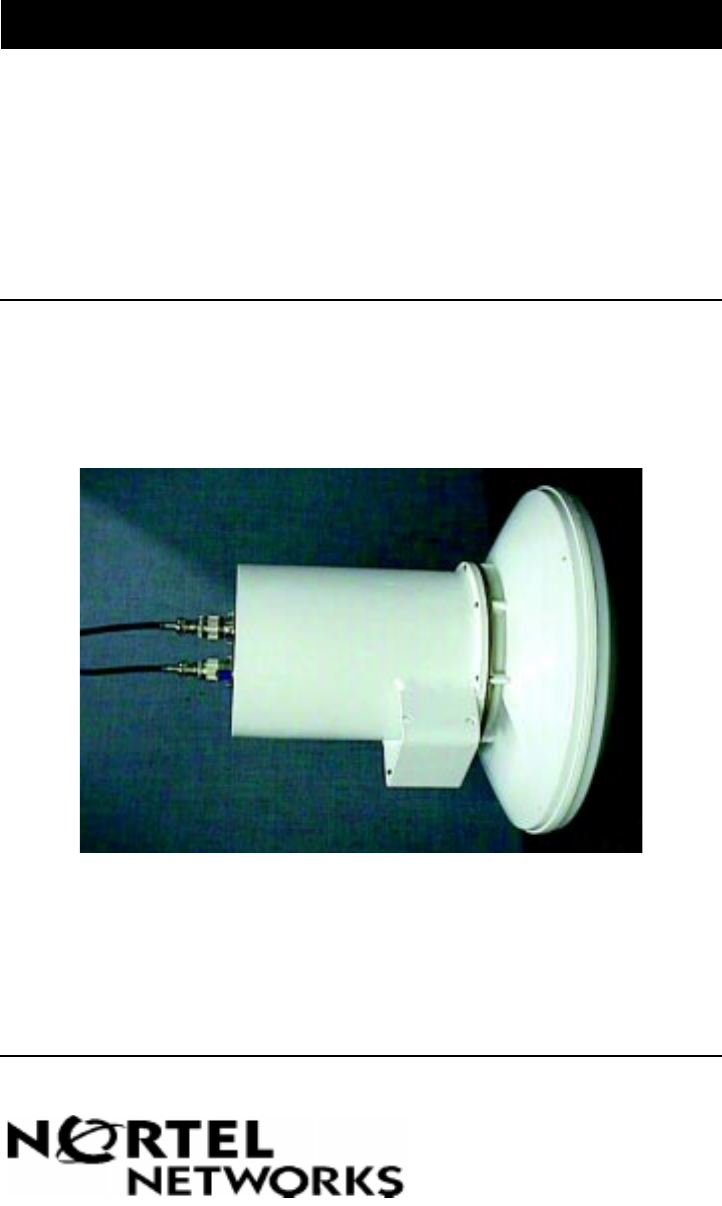
Product Overview
The CTR 28 GHz outdoor transceiver is a customer premise transceiver
designed to operate in the Receiver (RX) 27.5485 to 27.7485 GHz and
Transmitter (TX) 28.5565 to 28.7565 GHz frequency bands. It is a Nortel
Reunion product which operates in conjunction with base station products. It
is compatible with Reunion’s Release 1.2 equipment.
The CTR 28 GHz transceiver is mounted on a pole or a building. It features a
small size and low noise characteristics. The combination of digital
modulation and low-loss mounting results in an efficient and low-cost
installation. It has a high-stability reference oscillator.
The CTR 28 GHz features the following attributes:
• light-weight and compact packaging designed for mounting outdoors
• solid-state upconverter and downconverter designs
• high frequency stability over a wide temperature range
• standard 18 VDC input for use around the world
The transceiver comprises the following components:
•diplexer
• power supply
•mixers
• local oscillator
•isolators
• bandpass filters
• low noise amplifier (LNA)
• power amplifier
• duplexer
• antenna
1-2 CTR 28 GHz Release 1.2
411- 1333 - 203.01.02 Preliminary March 1999
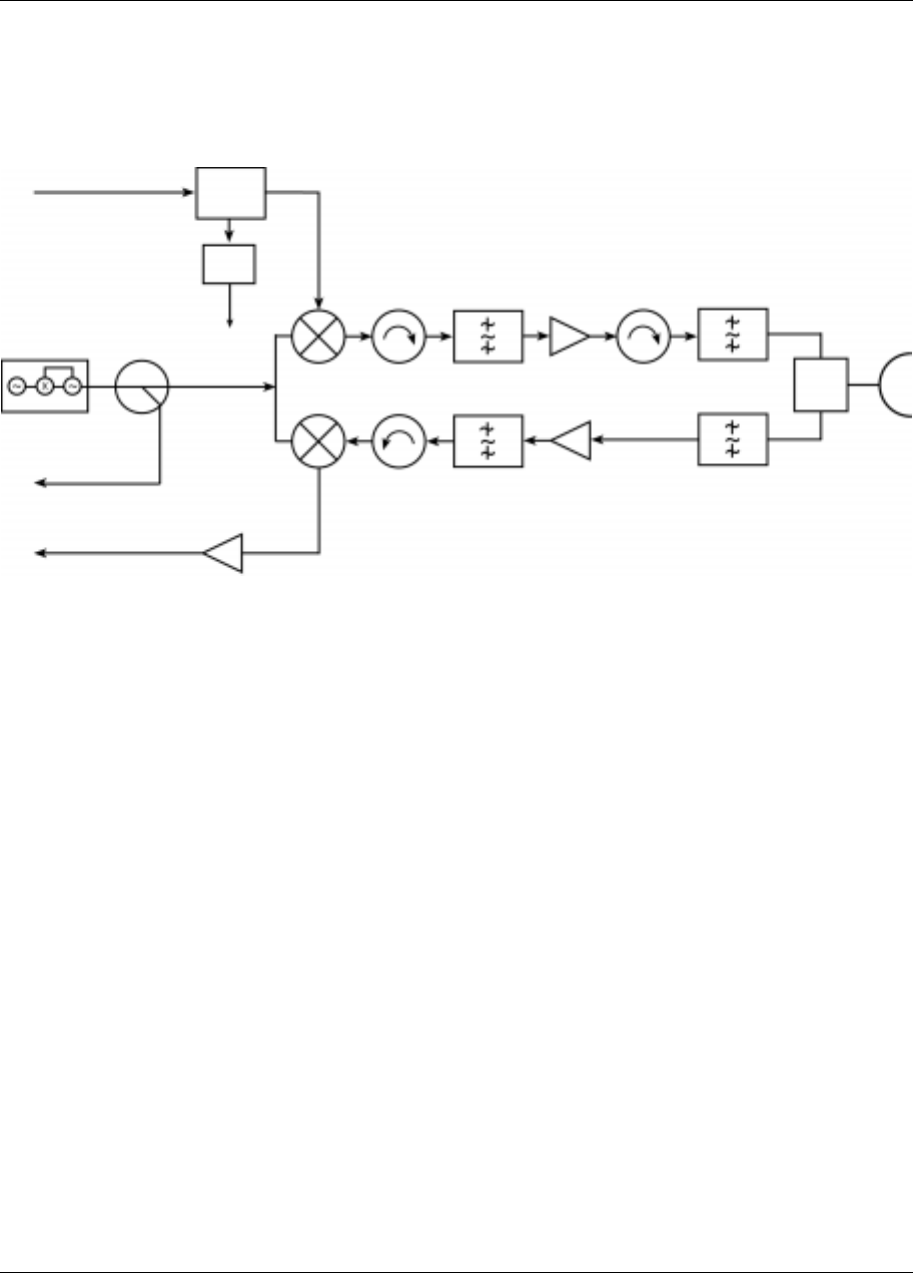
Figure 1-1
CTR 28 GHz Block Diagram
How the CTR 28 GHz Works
This section provides an overview of the theory of operation for the CTR 28
GHz outdoor transceiver.
Its installation on a pole or building enhances transmitting and receiving
capabilities by avoiding the need for long expensive waveguide runs. This
technique minimizes the power loss from waveguide attenuation, which
results in a highly efficient, compact and cost-effective installation. Minimum
maintenance is required.
The high-stability reference oscillator ensures that the transmitter and
receiver remain on frequency over a wide operating range.
The radio uses a common input cable to carry the 18 VDC and transmit
intermediate frequency (IF) signals. The DC power supply and the IF signals
are separated by the diplexer in the radio. The radio uses a common antenna
for both the transmit and receive microwave signals.
18 VDC Diplexer
12 VDC TX Filter P. Amp. TX Filter
Antenn
a
Duplexer
RX FilterLNARX Filter
VHF-AMP
IF Output
DRO
Mixer
Mixer
LO Test Port
IF/PS Input
Power Supply

CTR 28 GHz Release 1.2 1-3
Reunion CTR 28 GHz Installation Guide
1. The CTR transceiver’s input coaxial cable carries the IF signals and the 18
VDC power supply to the diplexer. The diplexer distributes the DC power
to the power supply unit and interfaces with the mixer for the IF signals.
2. The 450-650 MHz transmit IF signals enter the mixer which upconverts
the signals to the 28.5565-28.7565 GHz band for the transmit path. The
received 27.5485-27.7485 RF band is downconverted to a receive signal
in the 358-558 MHz range.
3. The local oscillator (LO) provides local oscillator signal to the mixer. The
LO uses a phase-locked dielectric resonance oscillator (DRO) with an
oven controlled crystal oscillator (OCXO).
4. The bandpass filters remove the undesired sideband signals, in both the
transmit and receive paths.
5. The upconverted signal is fed into the power amplifier which provides the
required gain to the microwave signals. The power amplifier output is
connected to the antenna through the filter and duplexer.
6. The received RF simultaneously passes through the antenna, the band
pass filter, the Low Noise Amplifier (LNA), and enters the downconverter
mixer.
There are three connectors on the outside of the transceiver case:
• The IF (TX) and power supply input uses a Type N female jack
• The IF (RX) output uses a Type N female jack
• Test Port uses SMA jack

1-4 CTR 28 GHz Release 1.2
411- 1333 - 203.01.02 Preliminary March 1999
CTR 28 GHz Specification
Table 1: CTR 28 GHz Specifications
TX IF Input RF Output
Frequency Range 28-01P1
28-01P2
28-07P
538-650 MHz 28.5565-28.6685 GHz
28.6405-28.7525 GHz
28.2-28.35 GHz
Output Level (P1dB) ≥21 dBm, -40° to +30°C
≥20.7 dBm, +31° to +50°C
≥20.2 dBm, +51° to +55°C
Output Level (IP3) >28 dBm, min.
Input Impedance 50 Ohms
Input/Output Connector N Type Female WR-28 Cover Flange
Input VSWR 1.8:1, max 1.6:1, max (or 13 dB)
Gain (not including
antenna) 22 dB
Gain Stability ±2.0 dB over temperature
Gain Flatness ±1 dB over bandwidth
Frequency Stability ±2 ppm, (-40° to +55°C)
RX RF Input IF Output
Frequency Range 28-01P1
28-01P2
27.5485-27.6605 GHz
27.6325-27.7445
358-470 MHz
Nominal Input Level - 26 dBm
Output Impedance 50 Ohms
Input/Output Connector WR-28 N Type Female
Output VSWR 1.6:1, max (or 13 dB) 1.8:1, max
Gain (not including
antenna) 34 dB, minimum
Gain Stability <±3.0 dB over temperature
Gain Flatness <±1.5 dB over bandwidth
Noise Figure < 8 dB, -40° to +30°C
< 8.3 dB, +31° to +50°C
< 8.7 dB, +51° to +55°C
Frequency Stability <±2.7 ppm, (-40° to +55°C)
Test Por t -20 SMA

CTR 28 GHz Release 1.2 1-5
Reunion CTR 28 GHz Installation Guide
Note: Use the following formula to calculate the converted frequency:
TX: ƒRF OUT (GHz) = ƒIF IN (GHz) + 28.1065
RX: ƒIF OUT (GHz) = 28.1065 - ƒRF IN (GHz)
Antenna CTR
Frequency 27.5-29.5 GHz
Gain 35 dBi, minimum
TX / RX wave polarity linear, single pole
Beam Width (3dB) 2.6°
Diameter 1’ (30.5 cm)
Power Supply CTR
Input Voltage 18 VDC, 3A, max
diplexed with TX cable
Input Current <3 Amp
Input Power 54 Watts, maximum
Environmental CTR
Humidity 100% condensing
Altitude 10,000 feet
Operating Temperature -40° to +55°C
Storage Temperature Range -45° to +85°C
Mechanical CTR
Size (Height x Diameter) 15.2" x 12.4" (38.5 x 31.5 cm)
Weight without brackets 7 lbs. (3.2 KG)

1-6 CTR 28 GHz Release 1.2
411- 1333 - 203.01.02 Preliminary March 1999
CTR 28 GHz Component Descriptions
Diplexer / Power Supply
The diplexer separates the IF input signals and the DC power supply. The
isolation between the IF path and the power supply path is more than 45 dB.
A transient voltage protector on the board helps to protect the transceiver
from possible lightning damage.
The 18 VDC power from the diplexer is first regulated to 12 VDC for all the
modules.
Mixer The CTR 28 GHz uses a third harmonic mixer. The mixer uses a 9.368833
GHz local oscillator (LO) signal to convert the IF input signals to the
27.5485-27.7485 GHz microwave frequency band. The same LO is used to
downconvert the incoming microwave signals to the receive IF frequency
band.
Dielectric Resonance Oscillator (DRO)
The Dielectric Resonance Oscillator is equipped with a OCXO reference
oscillator. When the DRO is phase-locked, it provides a 9.368833 GHz
microwave frequency stability derived from the reference crystal.
When the DRO is phase-locked, the phase-locked voltage at the test port on
the DRO can vary from 3 VDC to 10 VDC. The voltage at the alarm test port
is approximately 5 VDC.
When the DRO is unlocked, the phase-locked voltage becomes an oscillating
ramp wave. The voltage at the alarm test port goes down to 0 VDC.
IsolatorThree isolators provide adequate return loss in the CTR 28 GHz. Each
isolator’s maximum forward insertion loss is 0.5 dB, and its return loss is
greater than 18 dB.
Bandpass Filter
The bandpass filter removes the undesired sideband elements and LO
leakage, and passes the required sideband signals.

CTR 28 GHz Release 1.2 1-7
Reunion CTR 28 GHz Installation Guide
Low Noise Amplifier
The low noise amplifier (LNA) provides gain in the receive path and
amplifies the received microwave signals to the mixer. The gain and noise
figure of the LNA are chosen to maximize the overall dynamic range and
noise performance of the CTR 28 GHz receiver section.
Power Amplifier
The power amplifier provides gain in the transmit path. It boosts the signals in
the 28.5565-28.7565 GHz frequency range to the required level. The
amplifier is a solid state amplifier that has high linearity within a high output
power range.
Duplexer
The CTR 28 GHz uses the duplexer to combine and separate the transmit and
receive RF signals, allowing use of a common antenna for receiver and
transmitter.
Antenna
The CTR 28 GHz uses a reflector antenna to transmit and receive RF signals.
The transmitting signal polarity is defined as the direction of CTR 28 GHz
polarity.
Note: V= vertical TX wave polarization
H= horizontal TX wave polarization
Note: Lightening arrestors are not supplied with the CTR transceiver.
1-8 CTR 28 GHz Release 1.2
411- 1333 - 203.01.02 Preliminary March 1999
Pre-Installation
Prevention of Access
Allow only authorized personnel to access the equipment. Install the
equipment in a restricted-access location or similar environment. Failure to
prevent unauthorized user access invalidates the equipment warranty.
Unpacking Shipment
Use the following steps to unpack and inspect the shipment of Nortel Broadband
Wireless Access equipment:
1. Copy adequate Inventory Forms
2. Check each package against the order form and packing slip to ensure that
all components are received
3. Check each package for signs of damage
4. Open the package and closely inspect all components for obvious signs of
damage
5. Know exactly where you are going to place the equipment, before
removing them from the package
6. Carefully remove the equipment from the packaging
7. Save packing material for future use
8. Be aware of electrostatic discharge devices (ESD) requirements when
handling BWA equipment
Note: For more information, refer to the Electronic Industries
Association (EIA) standard, Requirements for Handling Electrostatic-
Discharge-Sensitive Devices (ESDS), EIA-625, as well as local and
national standards.

CTR 28 GHz Release 1.2 1-9
Reunion CTR 28 GHz Installation Guide
Reunion Safety Standards
Safety and safety considerations are important while using Nortel Broadband
Wireless Access equipment.
Safety Disclaimer
The safety standards discussed in this guide cannot address all safety
problems associated with their use or all applicable regulatory requirements.
The customers are responsible for establishing appropriate safety and health
practices and for determining the applicability of regulatory limitations before
their use.
General Safety
Ensure that installation personnel are trained on CPR (Cardio Pulmonary
Resuscitation), as well as on local, regional and national safety standards.
When working on Nortel Broadband Wireless Access equipment, follow these
guidelines:
• Keep your work site clean and free of clutter.
• Wear close fitting clothing.
• Remove jewelry such as rings, bracelets, or watches.
• Where it is possible to dislodge small pieces, wear eye protection.
• Place equipment or cabinets on level surfaces.
• Wear a safety belt when climbing a tower and installing equipment on a
tower.
• Work in pairs so that you have someone to help in case of an emergency.
Electrical Safety
Locate the main power shut-off switch controlling the equipment you are
working on. This is important in the event of an accident, so you can quickly
cut the power.
Disconnect all power when working on power supplies.
In an emergency (electrocution):
• shut the power off.
• have someone call for emergency medical assistance
•start CPR
Warning
Do not move in front of the antenna, nor look
directly into the face of the antenna when the CTR
28 GHz is running.

1-10 CTR 28 GHz Release 1.2
411- 1333 - 203.01.02 Preliminary March 1999
Installing the CTR 28 GHz
Installation involves three separate operations:
• mounting bracket assembly
• installing the tower equipment
• installing the indoor equipment
For information about installing the antenna(s) and such aspects as line of
sight, antenna mast spacing, coverage angle, etc., refer to the Network
Engineering Package and the Design Document.
Mounting Bracket Assembly
It is recommended that you assemble the mounting brackets on the ground
prior to mounting them on the pole. See Figures 1-7, 1-8, and 1-9.
Tools
You require the following tools to assemble the brackets:
i. Allen Key
ii. two open ended wrenches or a wrench and a socket
Steps
iBolt the two side supports onto either side of the ‘U bracket support.’
ii Align the holes in the U bracket with the holes in the ‘base support. Ensure that the
flat surface of the base support is in the upward position, while the curved/concave
surface faces downward.
iii Bolt the assembled U bracket support to the narrow end of the ‘base support.’
iv Position the assembled pole mounting hardware on the mounting pole at the point
you want to mount the CTR.
v Bolt the assembled mounting hardware to the two saddle brackets using the supplied
6" threaded bolts. Ensure that the bracket is securely tighten and correctly
positioned on the mounting pole before attaching the radio.
CTR 28 GHz Release 1.2 1-11
Reunion CTR 28 GHz Installation Guide
Installing the Tower Equipment
Install the CTR 28 GHz microwave transceiver as follows:
1. Mount the CTR 28 GHz to a stable pole using the supplied mounting
brackets. See Figures 1-7, 1-8, and 1-9.
The mounting brackets accommodate poles with outside diameters from
2" to 4.5". See Figures 1-5 and 1-6.
The CTR 28 GHz requires 18 VDC (3A) power supply unit.
2. Connect the IF/power supply input cable to the CTR’s N-type
IF IN 18 VDC port. See Figures 1-3 and 1-4.
3. Connect the RX cable from the CTR’s N-type IF OUT port to the RMM
RX port. See Figures 1-3 and 1-4.
4. Seal all connections using Coax-Seal® or equivalent, cold shrink or hot
shrink tubing.
5. Ground all RF cables at the recommended spacing intervals. (Refer to
tower and cable manufacturers’ specifications).
6. Ensure that all feed lines are securely attached to the support structure.
Plan for drip (service) loops on all cables.
Caution
Do not turn on the power supply until the
installation is complete. After you install the
equipment, check the cable connections.
1-12 CTR 28 GHz Release 1.2
411- 1333 - 203.01.02 Preliminary March 1999
Installing Indoor Equipment (NIU 5008 only)
Install the NIU 5008 equipment associated with the CTR 28 GHz microwave
transceiver as follows:
1. Connect the CPI 9000 (power inserter) to -48 VDC power source.
2. Adjust voltage out of CPI 9000. It is adjustable from 17V to 21V,
depending on cable length and type.
3. Connect power inserter unit’s IF IN port (N-type connector) to the NIU’s
IF OUT N-type (bulkhead) connector as shown in Figure 1-2.
4. Connect CTR 28 GHz IF/PS cable to the CPI 9000 output (PS/IF) port
(N-type connector).
5. Connect CTR 28 GHz RX cable to NIU IF IN N-type (bulkhead)
connector.
6. Refer to Reunion NIU 5008 Network Interface Unit Installation Guide,
Release 1.2, 411- 1323 - 203, and the Network Engineering Package.
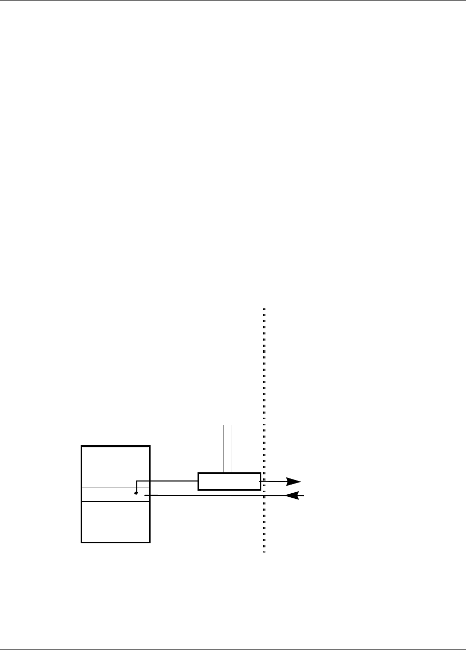
Figure 1-2
Diagram showing CTR 28 GHz indoor set-up
NIU
RMM
TX
RX
to CTR 28 GHz IF/PS
from CTR 28 GHz RX
CPI 9000
-48 DC
CTR 28 GHz Release 1.2 1-13
Reunion CTR 28 GHz Installation Guide
Installing Indoor Equipment (NIU 6054 only)
Install the NIU 6054 equipment associated with the CTR 28 GHz microwave
transceiver as follows:
1. Adjust voltage out of NIU 6054. It is adjustable from 17V to 21 V,
depending on cable length and type.
2. Connect CTR 28 GHz IF/PS cable to the NIU 6054’s output (PS/IF) port
(N-type connector).
3. Connect CTR 28 GHz RX cable to NIU N-type (bulkhead) connector.
4. Refer to Reunion NIU 6054 Network Interface Unit Installation Guide,
Release 1.1, 411- 1323 - 201, and the Network Engineering Package.
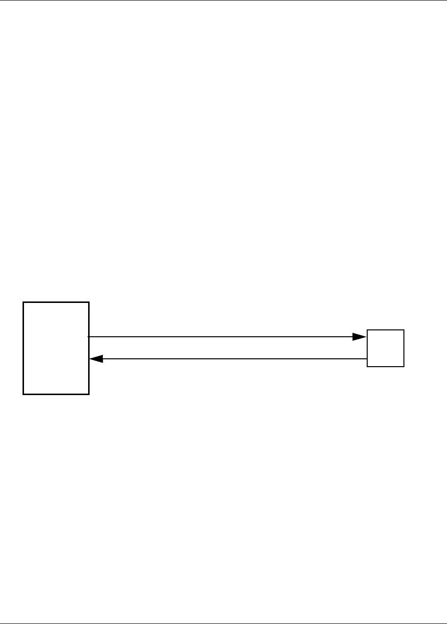
Figure 1-3
Block Diagram showing CTR 38 GHz indoor set-up with NIU 6054
NIU CTR
IF IN
IF OUT/DC Power IF IN/DC Power
IF OUT
1-14 CTR 28 GHz Release 1.2
411- 1333 - 203.01.02 Preliminary March 1999
Figure 1-4
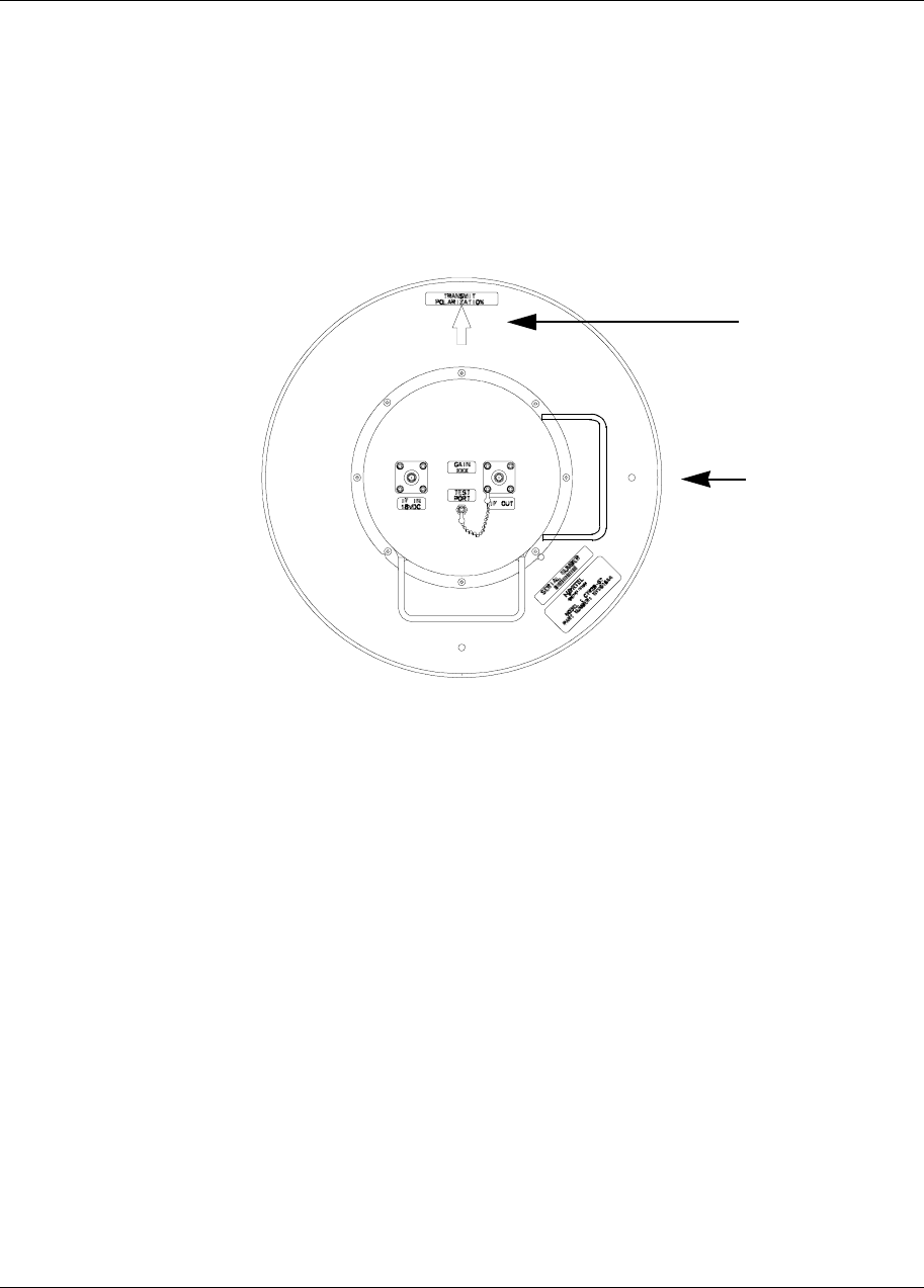
The CTR 28 GHz Back View-Showing Input and Output Points
IF IN
18 VDC IF OUT
Bracket
Drainage Hole
LO Test Port
Polarity Symbol
Drainage Hole
CTR 28 GHz Release 1.2 1-15
Reunion CTR 28 GHz Installation Guide
Figure 1-5
CTR 28 GHz Mounted to a Pole-Back View
U-Bracket Support
Drainage Hole
Polarity Symbol
Mounting Pole
IF IN
18 VDC IF OUT
LO Test Port
Drainage Hole
6 “ threaded bol
t
Base Support Saddles
1-16 CTR 28 GHz Release 1.2
411- 1333 - 203.01.02 Preliminary March 1999
Figure 1-6
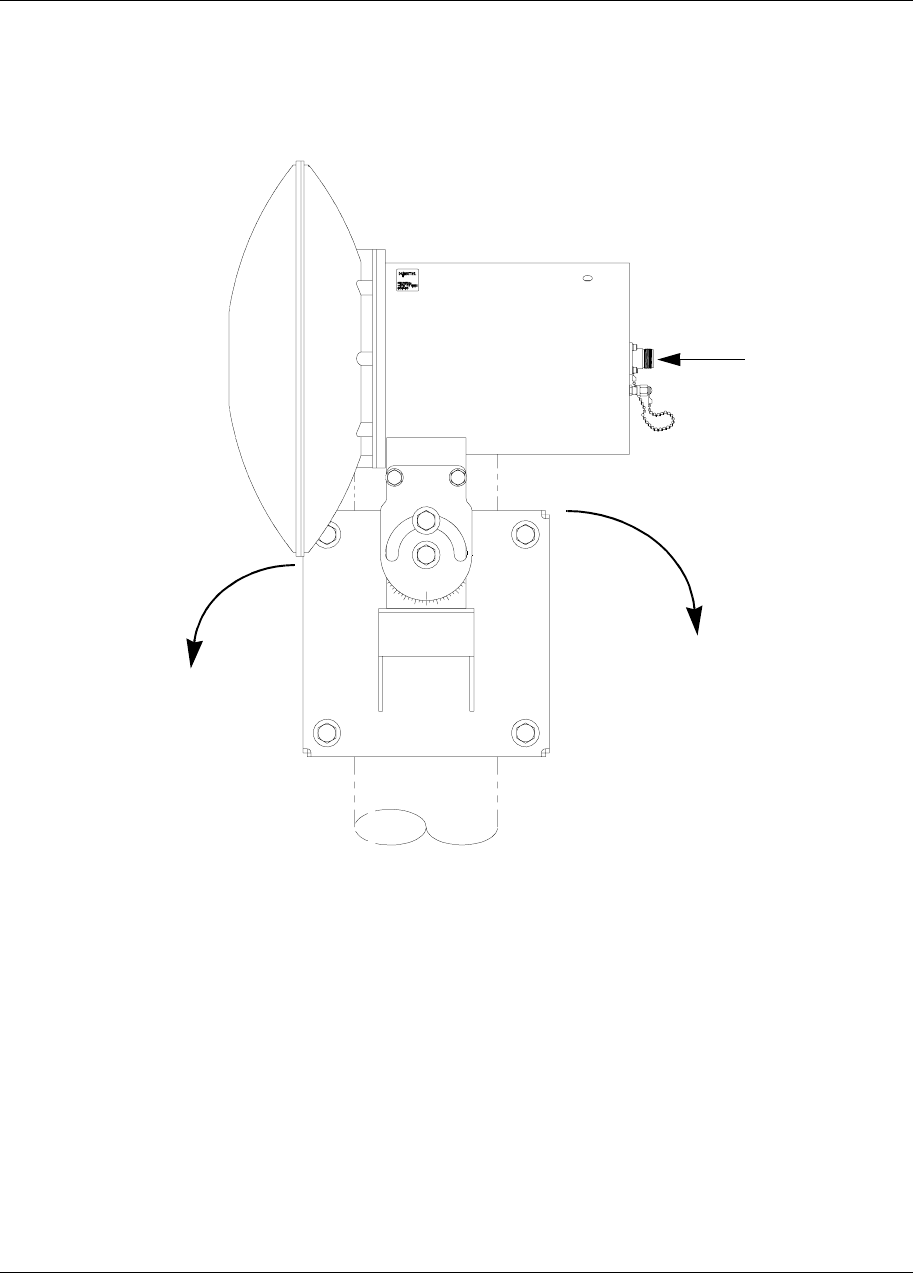
CTR 28 GHz Mounted on a Pole - Side View
CTR 28 GHz Connectors
Antenna Module
Mounting Pole
90°
55°
CTR 28 GHz Release 1.2 1-17
Reunion CTR 28 GHz Installation Guide
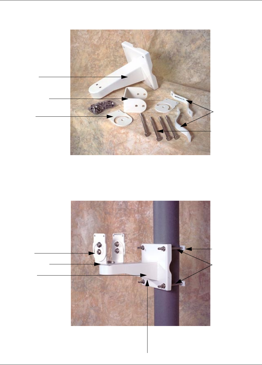
Figure 1-7
Bracket Components
Figure 1-8
Bracket Mounted on the Pole
Base Support
Bolts - 6” threaded
U Bracket Support
Side Support
Saddles for
pole mounting
Base Support
Bolts
U-Bracket Support
Side Support Saddle
U-Bracket Support
1-18 CTR 28 GHz Release 1.2
411- 1333 - 203.01.02 Preliminary March 1999
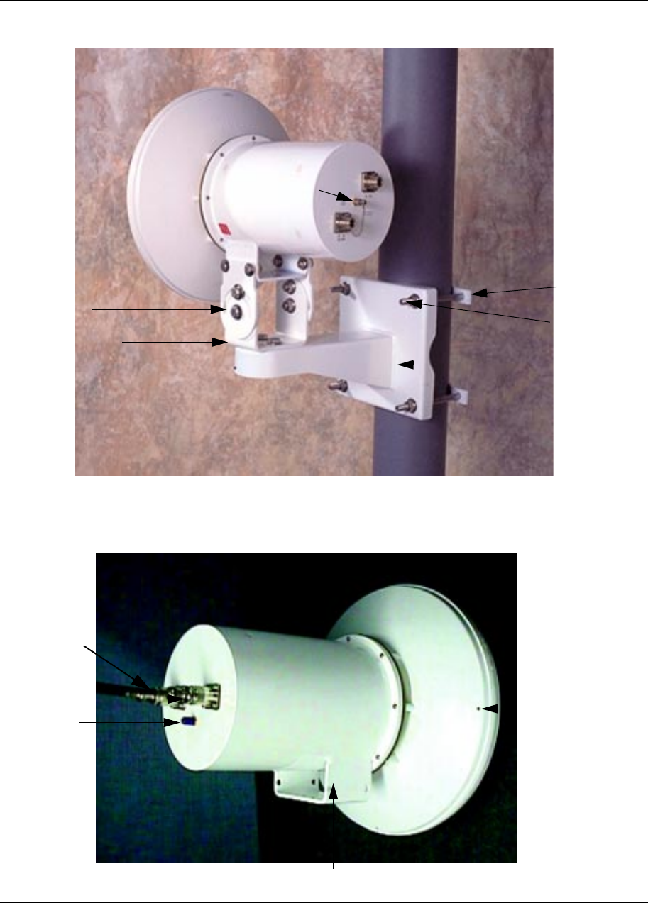
Figure 1-9
CTR mounted to a Pole
Figure 1-10
CTR 28 GHz with Connectors
IF IN
18 VDC
IF OUT
LO Test Port
Base Support
Bolt
U-Bracket Support
Side Support
Saddle
Note: This is a previous model of the CTR, however, it
shows bracket assembly.
IF Out
LO Test Port
IF In 18 VDC
Drainage Hole
U-Bracket Support
CTR 28 GHz Release 1.2 1-19
Reunion CTR 28 GHz Installation Guide
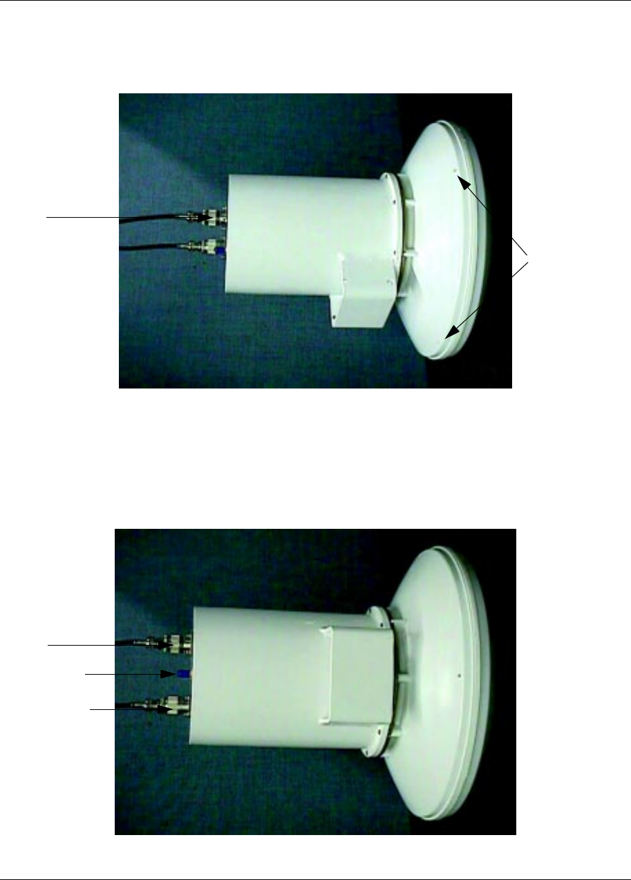
Figure 1-11
CTR 28 GHz Side View with Brackets
Figure 1-12
CTR 28 GHz Side View with Brackets
Drainage Holes
IF Out
LO Test Port
IF In 18 VDC
Drainage Hole
IF Out
LO Test Port
IF In 18 VDC

1-20 CTR 28 GHz Release 1.2
411- 1333 - 203.01.02 Preliminary March 1999
CTR 28 GHz Maintenance
Establish a regular check procedure. This quickly identifies any problem
which might develop. There are no repairable internal components in the CTR
28 GHz. Therefore, the checks focus on the exterior features of the
transceiver unit.
Mechanical Checks
Check the following mechanical areas to prevent problems.
1. Check the bolts and fasteners which hold the transceiver, waveguides, and
antenna. Vibrations due to wind can cause bolts and fasteners to loosen.
Verify that equipment is secure and properly mounted. If the bolts or
fasteners are loose, tighten them carefully. Use lock and spring washers.
2. Check to ensure that all connections between the transceiver and antenna
remain watertight. If water enters the waveguide or coaxial connections, it
can cause attenuation of the microwave signals. If water is detected, call
Nortel Broadband Wireless Access.
3. Visually inspect all equipment for signs of external damage. If signs of
damage are detected, call Nortel Broadband Wireless Access.
Note: If you detect an unsolvable problem during the electrical and
mechanical inspections, contact Nortel Networks Broadband Wireless
Access so that action can be taken to rectify the problem.
CTR 28 GHz Release 1.2 1-21
Reunion CTR 28 GHz Installation Guide
CTR 28 GHz Diagnostic Reference Chart
Symptom Possible Cause Check Procedure
Output power low 1. VHF input signal level low. a. Check VHF signal level.
b. Check coaxial cable.
c. Check cable connectors.
d. Check antenna for blockage (e.g. guano)
No power a. check main fuse power
b. check cable connections
If you detect any problem during the electrical and mechanical checks, contact Nortel Networks
Broadband Wireless Access so that action can be taken to rectify the problem.
Caution
Warranty void if seal is opened. This means do not
attempt to remove cover.
Caution
Warranty void if CTR is not equipped with
lightening arrestor.

1-22 CTR 28 GHz Release 1.2
411- 1333 - 203.01.02 Preliminary March 1999

2-1
Reunion CTR 28 GHz Installation Guide
2Grounding and Surge Protection
Grounding/Lightning Protection
Scope This chapter presents guidelines for the grounding and electrical protection of
Reunion equipment in typical buildings, assuming
1. indoor equipment is installed in an appropriate equipment room and
2. outdoor equipment is installed on rooftops using a pole mount.
Further, Nortel Networks assumes building electrical systems comply with
the appropriate national and local regulations.
Grounding Methods/Indoor Equipment
Components of a communications system can be grounded together using an
isolated bonding network (IBN). The IBN can be configured in several different
ways:
1. Mesh
2. Mesh – IBN with bonding mat
3. Star or sparse-mesh
In turn, the IBN is bonded at a single point to the Common Bonding Network
(CBN) that forms the principal bonding network in a building. Figure 2-1
shows a typical installation:
2-2 Grounding and Surge Protection
411- 1333 - 203.01.02 Preliminary March 1999
Figure 2-1
Typical Grounding configuration for Indoor Equipment
The single point ground (SPG) represents the connection of IBN to the
building grounding system.
Wire Gauge Guidelines
Main bonding conductors
All main bonding conductors in the equipment room shall be No. 2 AWG or
larger copper wires.
Other bonding conductors
All other bonding conductors in the room, including
• bonding individual frames/cabinets to the collector cable, supplementary
conductor or BPG
• bonding conductors of other metallic objects such as cable trays and
building utility equipment
are No. 6 AWG or larger insulated copper conductors.
SPG
Cabinet 1 Cabinet 2 Cabinet 3 Cabinet N
Mesh Connection
Collector Cable

Grounding and Surge Protection 2-3
Reunion CTR 28 GHz Installation Guide
Outdoor Equipment: the need for surge (lightning) protection
Apart from the need to provide good grounding for safety, outdoor equipment
is subject to more environmental hazards than is indoor equipment. Radio
communication equipment, with antennas mounted well above ground level,
have conductive parts exposed to lightning.
Safety needs are met by grounding practices and protection needs are met by a
combination of grounding and protective devices. Many protective devices are
available:
• air terminals,
• solid state OVPs,
• filters,
•zeners,
• MoVs,
•isolators
• capacitors,
• resistors,
• QWS and more.
The application of these devices is beyond the scope of this document. The
equipment designer needs to consider both the protection requirements and
the geographic region where the equipment is installed.
Grounding and Lightning Protection
In general, all exposed metallic equipment must be grounded. Besides the
need for lightning protection, it is desirable to conduct induced current to
ground through as low a resistance as possible, along as short a path as
possible.
In practice this means multiple ground connections and multiple conductors.
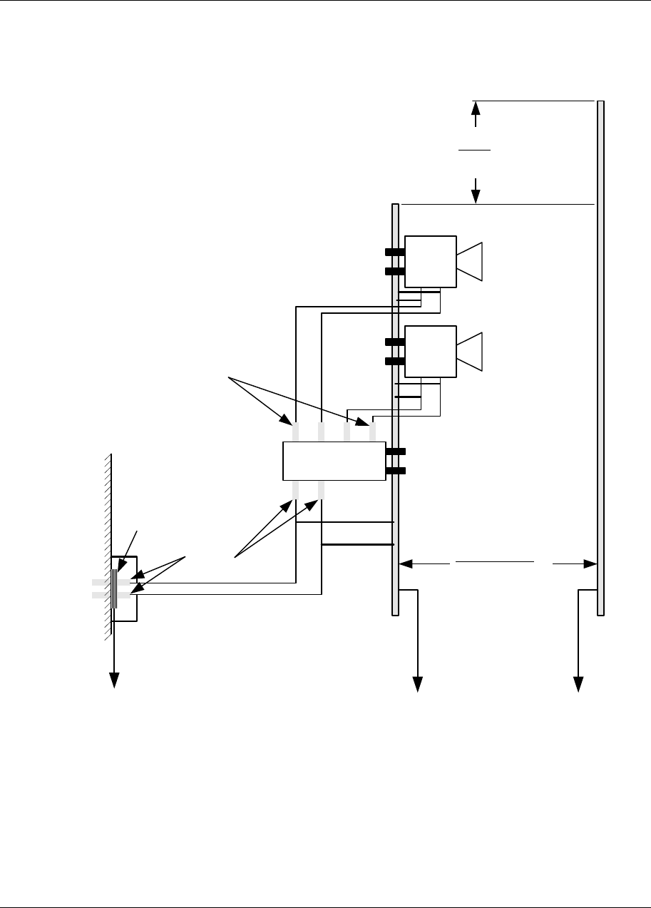
Figure 2-2 shows a typical rooftop installation of Reunion customer premise
equipment. Figure 2-3 shows a typical rooftop installation of Reunion base
station transceiver (BTR).
The radio equipment should, where possible, be grounded through the ground
lug using a 6AWG bonding wire to the building common bonding network.
Alternatively, the equipment can be grounded through the mounting bracket.
Provision must be made to prevent corrosion on the metallic contact surfaces.
Similarly, the installer shall ensure that there is a good metallic connection to
the building CBN.
If a common mounting plate is used for the two redundant BTRs and the radio
power extractor (RPE), the installer shall insure that ground continuity to the
CBN is maintained and corrosion protection is applied. The common
2-4 Grounding and Surge Protection
411- 1333 - 203.01.02 Preliminary March 1999
mounting plate should be considered as an alternative bonding to the
preferred technique of separately bonding each BTR and RPE. The size of the
bonding wire should be #6 AWG.
The coaxial cable shall be bonded at least at the RPE/BTR/CTR and at the
building entry. For a tower higher than 30 meters (98 ft), the cable shall be
bonded at 30 meter intervals. The size of the bonding conductor shall be #6
AWG or larger.
Mount the radio in an area protected from lightning strikes. If local conditions
require an air terminal, install it in accordance with ANSI/NFPA 780. The air
terminals are shown schematically in Figures 1-2 and 1-3. The air terminal
(lightning rod) if used, is at least 1 meter (3.3 ft) above the highest object
being protected and within 2 meters (6.6 ft) ± 30 cm (1.0 ft) of the object.
Caution
Do not install Reunion equipment on lightning
protection air terminals.
Grounding and Surge Protection 2-5
Reunion CTR 28 GHz Installation Guide
Figure 2-2
Rooftop Installation of Reunion Base Radio Equipment
NOTE
The outer coaxial cable conductor is
bonded (grounded) at the building
entrance and at the customer
premise transceiver (CTR).
Surge
arrestors
Lightning
rod
Building
entrance
Grounding
plate
to common
bonding network
to common
bonding network
2 m ± 30 cm
6.6 ± 1.0 ft
Steel pipe
mount
6.4 cm
(2.5 in.)
1 m
3.3 ft
CTR
2-6 Grounding and Surge Protection
411- 1333 - 203.01.02 Preliminary March 1999
Figure 2-3
Rooftop Installation of Reunion Base Radio Equipment
NOTE
The outer conductor of the coaxial
cable is grounded at the building
ground’s entrance and at the BTR.
On the building side, the RPE
comes equipped with surge
arrestors.
Lightning
rod
to common
bonding network
2 m ± 30 cm
6.6 ± 1.0 ft
Steel pipe
mount
6.4 cm
(2.5 in.)
1 m
3.3 ft
BTR
BTR
Building
entrance
Grounding
plate
to common
bonding network
RPE
Surge
arrestors
Surge
arrestors
Redundant
radios

Grounding and Surge Protection 2-7
Reunion CTR 28 GHz Installation Guide
Ground connections to outdoor equipment
The grounding lug is supplied with all current releases of outdoor brackets. In
addition, a 6 AWG braided ground wire connected to the common bonding
network is required to complete the ground connection for all microwave
products.
Note: There is no grounding lug supplied with previously-released
microwave products. To retrofit these installations, order one retrofit kit
for each sector and use the following procedures.
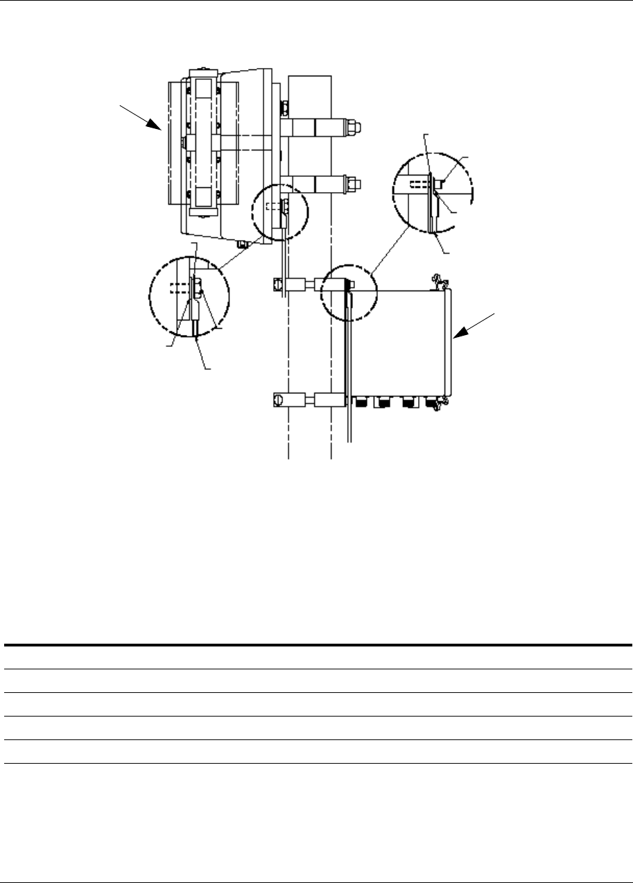
Retrofit procedure for grounding the base station equipment
(BTR and RPE)
You will need an NTVG15BA BTR and RPE grounding retrofit kit for every
base station sector to be retrofitted, containing the following parts:
Use the following method to install the kit on the BTR, referring to Figure 2-4:
1Remove the 3/8” mounting bolt, two flat washers and the mounting
washer from the BTR. Discard one flat washer and the locking washer.
2Crimp the 3/8 terminal (A0297956) onto the grounding wire.
3Install the existing bolt, flat washer, new internal tooth washer, and the
complete ground cable as shown in Figure 2-4.
Use the following method to install the kit on the RPE, referring to Figure 2-4:
1Remove the 1/4” mounting bolt and split lock washer as shown in
Figure 2-4.
2Crimp the 1/4 terminal (A0315080) onto the grounding wire.
3Install the ¼” original mounting bolt and a stainless steel internal tooth
washer.
4Repeatedly tighten and loosen the fastener assembly, rotating the
internal tooth lock washer, until the powder coating is scraped off and
the bare metal is exposed. Repeat this procedure if required.
5Discard the internal tooth washer used to remove the powder coating.
6Using new stainless steel internal tooth washers, assemble the complete
ground cable connection, as per Figure 2-4.
Item Qty Vendor part no. Description CPC no.
1 2 LCA6-38 6 AWG, 3/8” compression terminal (Panduit) for BTR A0297956
2 1 LCA6-14 6 AWG, 1/4” compression terminal (Panduit) for RPE A0315080
3 2 W-2064 1/4” Stainless steel internal tooth lock washer (Spaenaur) for RPE TBD
4 2 W-2069 3/8” Stainless steel internal tooth lock washer (Spaenaur) for BTR TBD
2-8 Grounding and Surge Protection
411- 1333 - 203.01.02 Preliminary March 1999
Figure 2-4
Grounding the BTR and RPE
Retrofit procedure for grounding the customer premise
equipment (CTR)
You will need an NTVG15CA CTR grounding retrofit kit for every CTR to be
retrofitted, containing the following parts:
Item Qty Vendor part no. Description CPC no.
1 5 LCA6-38 1/4” Stainless steel internal tooth lock washer (Spaenaur) TBD
2 1 LCA6-14 6 AWG, 1/4” compression terminal (Burndy) for CTR A0315080
3 3 1/4” stainless steel flat washer P0883797
4 1 1/4” x 1” Stainless steel hex head bolt P0888501
5 2 MS35649-2254 1/4” Stainless steel nut P0860421
Internal tooth
lock washer
Existing
flat washer
Existing
Hex head
capscrew
Cable (not
provided)
Internal tooth lock
washer
Existing
socket head
capscrew
Existing split
lock washer
Cable (not
provided)
BTR
RPE
Grounding and Surge Protection 2-9
Reunion CTR 28 GHz Installation Guide
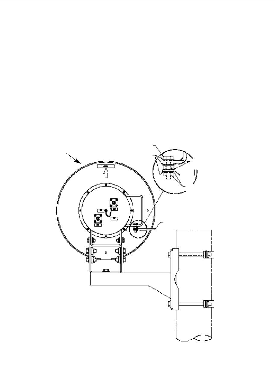
Use the following method to install the kit on the CTR, referring to Figure 2-5:
1Install the ¼” stainless steel hex bolt, stainless steel flat washer and the
stainless steel internal tooth washer through one of the four holes in the
CTR. (Refer to Figure 2-5 for the hole location.)
2Install a stainless steel internal tooth washer, stainless steel flatwasher
and the 1/4” nut onto the assembly installed in Step 1.
3Repeatedly tighten and loosen the fastener assembly, rotating the
internal tooth lock washer, until the powder coating is scraped off and
the bare metal is exposed. Repeat this procedure if required.
4 Discard the internal tooth washer used to remove the powder coating.
5Using new stainless steel internal tooth washers, assemble the complete
ground cable connection, as per Figure 2-5.
Figure 2-5
Grounding the CTR
Hex head
capscrew
Flat washer Internal tooth
Lock washer
Hex nut
Cable (not provided)
CTR

2-10 Grounding and Surge Protection
411- 1333 - 203.01.02 Preliminary March 1999
Regulatory Considerations
Electrical
1. UL1950/IEC950
Lightning protection
1. UL1492
2. IEC 65
3. IEEE/ANSI C62.41
4. Bellcore GR-1089-CORE
5. ANSI/NFPA 780 Lightning Protection Code
Grounding
1. CCITT Rec K.27
2. Corporate Standard 4122, Grounding of Communication Systems
It is assumed that building construction complies with NEC Article 250 (US)
or CEC Section 10 (Canada). In the US the recommended ground resistance
is 5 ohms and the maximum for a single electrode is 25 ohms.

3-1
Reunion CTR 28 GHz Installation Guide
3List of terms
ACAlternating Current
Air Terminal
Another name for lightning rod
AWG
American Wire Gauge
DBMS
Digital Broadband Microwave System
DCDirect Current
DRO
Dielectric Resonance Oscillator
Earthing
Another term for grounding used by safety agencies. Earthing is the term often seen in
safety standards.
EIAElectronic Industries Association
ESD
Electrostatic Discharge
FCC
Federal Communications Commission
IBN
Isolated Bonding Network

3-2 List of terms
411- 1333 - 203.01.02 Preliminary March 1999
IC Industry Canada
IF Intermediate Frequency
kHz
kilohertz, one thousand hertz or cycles per second
LOLocal Oscillator
LNA
Low Noise Amplifier
LNB
Low Noise Block Downconverter
MHz
MegaHertz, one million hertz or cycles per second
NIU
Network Interface Unit
OCXO
Oven-Controlled Crystal Oscillator
PAPower Amplifier
PI Power Inserter
PS Power Supply
QAM
Quadrature Amplitude Modulation, which entails modulating frequency
RF Radio Frequency
RMM
Radio Modem Module

List of terms 3-3
Reunion CTR 28 GHz Installation Guide
SPG
Single Point Ground
VAC
Voltage Alternating Current
VDC
Voltage Direct Current (Volts Direct Current)
VHF
Very High Frequency

3-4 List of terms
411- 1333 - 203.01.02 Preliminary March 1999
Family Product Manual Contacts Copyright Confidentiality Legal statements DocInfo

Reunion
CTR 28 GHz
Installation Guide
Nortel Broadband Wireless Access
14 Fultz Blvd.
Winnipeg, Manitoba R3Y 1V3
Phone: 972-BWA-ETAS/972-292-3827; Fax: 204-631-2475
1-800-4-NORTEL (1-800-466-7835)
http://www.nortel.com
1999 Northern Telecom
Northern Telecom Ltd., all rights reserved
NORTHERN TELECOM CONFIDENTIAL:
The information contained in this document is the property of
Northern Telecom. Except as specifically authorized in writing by
Northern Telecom, the holder of this document shall keep the
information contained herein confidential and shall protect same
in whole or in part from disclosure and dissemination to third
parties and use same for evaluation, operation, and
maintenance purposes only.
Information is subject to change without notice.
Publication number: 411- 1333 - 203.01.02
Product release : Release 1.2
Document version: Preliminary
Date: March 1999
Printed in Canada