Nortel Networks 2500 Series Users Manual Ethernet Routing Switch Overview — System Configuration
2500 Series to the manual a44d284b-5b1f-4190-99cf-dfc4326f0800
2015-01-26
: Nortel-Networks Nortel-Networks-2500-Series-Users-Manual-346497 nortel-networks-2500-series-users-manual-346497 nortel-networks pdf
Open the PDF directly: View PDF ![]() .
.
Page Count: 392 [warning: Documents this large are best viewed by clicking the View PDF Link!]
- Overview — SystemConfiguration
- Contents
- New in this release
- Introduction
- Ethernet Routing Switch 2500 Series hardware
- Nortel Ethernet Routing Switch 2500 Series stacking
- Stacking capabilities
- Stacking functionality delivery
- Stack configuration
- Configuring the operational mode on rear ports using the CLI
- rear-ports mode command
- show rear-ports mode command
- Configuring the operational mode of rear ports using the Device Manager
- Rear ports and stacking
- Initial stack installation
- Stack MAC address
- Stack configurations
- Temporary base unit
- Redundant cascade stacking
- Removing a stack unit
- Adding/Replacing a stack unit
- Auto Unit Replacement
- System configuration software features
- Switch management features
- Configuration and switch management
- Console port settings
- Switch banner
- User name and password
- Logging in
- Autosave feature
- Using SNTP
- Using DNS to ping and Telnet
- BootP automatic IP configuration/MAC address
- Choosing a BootP request mode
- Flash memory storage
- Configuration File Download/Upload
- Requirements
- Binary configuration file
- ASCII configuration file
- Autotopology
- Link Layer Discovery Protocol (IEEE 802.1ab)
- Ethernet port management features
- Other features
- Switch management features
- CLI Basics
- Getting Started with Device Manager
- Installing Device Manager
- JDM installation precautions
- Installing the Device Manager software
- Installing JDM on Windows
- Installing JDM on UNIX or Linux
- Device Manager basics
- Starting Device Manager
- Setting the Device Manager properties
- Opening a device
- Device Manager window
- Editing objects
- Working with statistics and graphs
- Telnet session
- Opening an SSH connection to the device
- Opening the web-based management home page
- Trap log
- Online Help
- Using the Web-based management interface
- Power over Ethernet for the Ethernet Routing Switch 2526T-PWR and 2550T-PWR
- System configuration using the CLI
- Configuring the switch IP address, subnet mask and default gateway
- Resetting the switch to default configuration
- Using DNS to ping and telnet
- Configuration Management
- Customizing your system
- Displaying the ARP table
- Displaying interfaces
- Saving the configuration to NVRAM
- Enabling and disabling autosave
- Setting time on network elements using Simple Network Time Protocol
- Setting local time zone
- Enabling Autopology
- Configuring LLDP using the CLI
- lldp command
- default lldp command
- lldp config-notification command
- no lldp config-notification command
- default lldp config-notification command
- lldp tx-tlv command
- no lldp tx-tlv command
- default lldp tx-tlv command
- lldp status command
- no lldp status command
- default lldp status command
- show lldp command
- show lldp port command
- Configuring LEDs to blink on the display panel
- Upgrading software
- Ethernet port management using the CLI
- Configuring the switch using Device Manager
- Configuring ports using Device Manager
- Administering the switch using web-based management
- Configuring the switch using web-based management
- Configuring BootP, IP, and gateway settings
- Modifying system settings
- Configuring switch port status
- Configuring high speed flow control
- Downloading switch images
- Downloading ASCII configuration files
- Storing and retrieving a switch configuration file from a TFTP server
- Enabling and disabling autosave
- Configuring port communication speed
- Configuring Rate Limiting
- Troubleshooting
- DB-9 (RS-232-D) Console/Comm Port connector
- Default settings
- Sample BootP configuration file
- Command List
- Technical specifications
- Index
- Figures
- Figure 1 Ethernet Routing Switch 2550T-PWR
- Figure 2 Ethernet Routing Switch 2526T front panel
- Figure 3 Ethernet Routing Switch 2550T front panel
- Figure 4 Ethernet Routing Switch 2526T-PWR front panel
- Figure 5 Ethernet Routing Switch 2550T-PWR front panel
- Figure 6 LED display panel
- Figure 7 Ethernet Routing Switch 2500 Series back panel
- Figure 8 Ethernet Routing Switch 2500 Series used as a desktop switch
- Figure 9 Ethernet Routing Switch 2500 Series used as a workgroup switch
- Figure 10 Configuring power workgroups and a wiring closet switch
- Figure 11 show license all command output
- Figure 12 License Download page
- Figure 13 show rear-ports mode command output
- Figure 14 Rear panel components
- Figure 15 CFG mirror process in stack
- Figure 16 CFG mirror images in the stack after adding unit 4
- Figure 17 CFG mirror images after removing unit 4
- Figure 18 CFG mirror images in the stack after removing the BU (unit 1)
- Figure 19 CFG mirror images in the stack after adding unit 5
- Figure 20 Login banner
- Figure 21 Login screen
- Figure 22 How LLDP works
- Figure 23 CLI command mode hierarchy
- Figure 24 help command output
- Figure 25 show sys-info command output
- Figure 26 show tech command output
- Figure 27 show mac-address-table command output
- Figure 28 InstallAnywhere Introduction dialog box
- Figure 29 InstallAnywhere Introduction dialog box
- Figure 30 Device Manager window
- Figure 31 Default Properties dialog box
- Figure 32 Open Device dialog box
- Figure 33 Parts of the Device Manager window
- Figure 34 Objects in the device view
- Figure 35 Interface tab
- Figure 36 Color port legend
- Figure 37 Switch unit shortcut menu
- Figure 38 Port shortcut menu
- Figure 39 Line graph
- Figure 40 Area graph
- Figure 41 Bar graph
- Figure 42 Pie graph
- Figure 43 Interface statistics for a single port
- Figure 44 Interface statistics for multiple ports
- Figure 45 Statistics dialog box for a port
- Figure 46 Web-based management home page
- Figure 47 Menu
- Figure 48 Console page
- Figure 49 Stack Information page
- Figure 50 Switch Information page
- Figure 51 Stack Numbering page
- Figure 52 Identifying Unit Numbers page
- Figure 53 show poe-main-status command output
- Figure 54 show poe-port-status command output
- Figure 55 show poe-power-measurement command output
- Figure 56 show ip command output
- Figure 57 show ip address command output
- Figure 58 ping command responses
- Figure 59 show ip dns command output
- Figure 60 ping command responses
- Figure 61 show config-network command output
- Figure 62 show running-config command output
- Figure 63 show terminal command output
- Figure 64 show cli command output
- Figure 65 show sys-info command output
- Figure 66 show tftp-server command output
- Figure 67 show arp-table command output
- Figure 68 show interfaces names command output
- Figure 69 show interfaces command output
- Figure 70 show interfaces verbose command output
- Figure 71 show interfaces config command output
- Figure 72 show autosave command output
- Figure 73 show sntp command output
- Figure 74 show clock time-zone output
- Figure 75 show clock summer-time
- Figure 76 show autotopology settings command output
- Figure 77 show autotopology nmm-table command output
- Figure 78 show lldp local-sys-data command output
- Figure 79 show lldp mgmt-sys-data command output
- Figure 80 show lldp stats command output
- Figure 81 show lldp port neighbor command output
- Figure 82 show lldp port neighbor-mgmt-addr command output
- Figure 83 show lldp port rx-stats command output
- Figure 84 show lldp port tx-stats command output
- Figure 85 show lldp port tx-tlv command output
- Figure 86 download message
- Figure 87 shutdown port command output
- Figure 88 show rate-limit command output
- Figure 89 show auto-negotiation-advertisements command output
- Figure 90 show auto-negotiation-capabilities command output
- Figure 91 Unit dialog box
- Figure 92 Globals tab
- Figure 93
- Figure 94 Telnet window with default banner
- Figure 95 FileSystem - Config/Image/Diag File tab dialog box
- Figure 96 File system - ASCII Config File dialog box
- Figure 97 Save Config tab
- Figure 98 SNTP_Clock dialog box
- Figure 99 Diagnostics dialog box Topology tab
- Figure 100 Diagnostics dialog box Topology Table tab
- Figure 101 LLDP Globals tab
- Figure 102 LLDP Port tab
- Figure 103 TX Stats tab
- Figure 104
- Figure 105 RX Stats tab
- Figure 106
- Figure 107 Local System tab
- Figure 108 Local Port tab
- Figure 109 Local Management tab
- Figure 110 Neighbor tab
- Figure 111 Neighbor Mgmt Address tab
- Figure 112 Organizational Defined Info tab
- Figure 113 Port dialog box Interface tab
- Figure 114 Interface tab for multiple ports
- Figure 115 System Information page
- Figure 116 Quick Start page
- Figure 117 Reset page
- Figure 118 Reset page message
- Figure 119 Reset to Default page message
- Figure 120 Logout message
- Figure 121 IP page
- Figure 122 System page
- Figure 123 Port Management page
- Figure 124 High Speed Flow Control page
- Figure 125 Software Download page
- Figure 126 Ascii Configuration file download page
- Figure 127 Configuration File
- Figure 128 Console/Communication Port page
- Figure 129 Rate Limiting page
- Figure 130 DB-9 Console port connector
- Tables
- Table 1 Components on the Ethernet Routing Switch 2500 front panel
- Table 2 Ethernet Routing Switch 2500 Series LED descriptions
- Table 3 Components on the Ethernet Routing Switch 2500 Series back panel
- Table 4 International power cord specifications
- Table 5 show license command parameters
- Table 6 License Download page fields
- Table 7 rear-ports mode command
- Table 8 Parameters not saved to the configuration file
- Table 9 Command mode prompts and entrance/exit commands
- Table 10 Keystroke navigation
- Table 11 configure command parameters and variables
- Table 12 interface command parameters and variables
- Table 13 reload command parameters and variables
- Table 14 shutdown command parameters and variables
- Table 15 show mac-address-table command parameters and variables
- Table 16 mac-address-table aging-time command parameters and variables
- Table 17 Properties dialog box fields
- Table 18 SNMP community string default values
- Table 19 Open Device dialog box fields
- Table 20 Menu bar commands
- Table 21 Toolbar buttons
- Table 22 Selecting multiple objects
- Table 23 Port color codes
- Table 24 Switch unit shortcut menu command
- Table 25 Port shortcut menu commands
- Table 26 Device Manager buttons
- Table 27 Types of statistics
- Table 28 Graph dialog box buttons
- Table 29 Help file locations
- Table 30 Main headings and options
- Table 31 Menu icons
- Table 32 Page icons
- Table 33 Switch Information page fields
- Table 34 poe poe-pd-detect-type command parameters and variables
- Table 35 poe poe-power-usage-threshold command parameters and variables
- Table 36 no poe-shutdown command parameters and variables
- Table 37 poe poe-shutdown command parameters and variables
- Table 38 poe poe-priority command parameters and variables
- Table 39 poe poe-limit command parameters and variables
- Table 40 show poe-port-status command parameters and variables
- Table 41 show poe-power-measurement command parameters and variables
- Table 42 Global Power Management page items
- Table 43 Port Property page items
- Table 44 PoE tab items for a single unit
- Table 45 Port power color codes
- Table 46 PoE tab items
- Table 47 ip address command parameters and variables
- Table 48 ip default-gateway command parameters and variables
- Table 49 show ip command parameters and variables
- Table 50 show ip address command parameters and variables
- Table 51 ping command parameters and variables
- Table 52 ping command parameters and variables
- Table 53 ip name-server command parameters and variables
- Table 54 no ip name-server command parameters and variables
- Table 55 ip domain-name command parameters and variables
- Table 56 configure network command parameters and variables
- Table 57 copy running-config tftp command parameters and variables
- Table 58 terminal command parameters and variables
- Table 59 show cli command parameters and variables
- Table 60 boot command parameters and variables
- Table 61 ip bootp server command parameters and variables
- Table 62 tftp-server command parameters and variables
- Table 63 copy config tftp command parameters and variables
- Table 64 copy tftp config command parameters and variables
- Table 65 banner command parameters
- Table 66 show banner command parameters and variables
- Table 67 show interfaces command parameters and variables
- Table 68 show interfaces config command parameters and variables
- Table 69 sntp server primary address command parameters and variables
- Table 70 sntp server secondary address command parameters and variables
- Table 71 no sntp server command parameters and variables
- Table 72 sntp sync-interval command parameters and variables
- Table 73 default sntp command parameters and variables
- Table 74 clock time-zone command parameters and variables
- Table 75 clock summer-time command parameters and variables
- Table 76 lldp command parameters and variables
- Table 77 default lldp command parameters and variables
- Table 78 lldp config-notification command parameters and variables
- Table 79 no lldp config-notification command parameters and variables
- Table 80 default lldp config-notification command parameters and variables
- Table 81 lldp tx-tlv command parameters and variables
- Table 82 no lldp tx-tlv command parameters and variables
- Table 83 default lldp tx-tlv command parameters and variables
- Table 84 lldp status command parameters and variables
- Table 85 no lldp status command parameters and variables
- Table 86 default lldp status command parameters and variables
- Table 87 show lldp command parameters and variables
- Table 88 show lldp port command parameters and variables
- Table 89 blink-leds command parameters and variables
- Table 90 download command parameters and variables
- Table 91 shutdown port command parameters and variables
- Table 92 no shutdown command parameters and variables
- Table 93 name command parameters and variables
- Table 94 no name command parameters and variables
- Table 95 default name command parameters and variables
- Table 96 speed command parameters and variables
- Table 97 default speed command parameters and variables
- Table 98 duplex command parameters and variables
- Table 99 default duplex command parameters and variables
- Table 100 flowcontrol command parameters and variables
- Table 101 no flowcontrol command parameters and variables
- Table 102 default flowconrtol command parameters and variables
- Table 103 rate-limit command parameters and variables
- Table 104 show auto-negotiation-advertisements command
- Table 105 show auto-negotiation-capabilities command
- Table 106 auto-negotiation-advertisements command
- Table 107 no auto-negotiation-advertisements command
- Table 108 default auto-negotiation-advertisements command
- Table 109 Unit tab fields
- Table 110 Rate Limit tab fields
- Table 111 Rear Ports Mode tab fields
- Table 112 Globals tab fields
- Table 113 Addresses tab fields
- Table 114 ARP tab fields
- Table 115 TCP tab fields
- Table 116 UDP Listeners tab fields
- Table 117 System tab fields
- Table 118 Base Unit Info tab fields
- Table 119 Agent tab fields
- Table 120 Power Supply tab fields
- Table 121 Fan tab fields
- Table 122 FileSystem Config/Image/Diag file dialog box fields
- Table 123 ASCII Config File tab fields
- Table 124 Save Configuration tab fields
- Table 125 SNTP_Clock dialog box fields
- Table 126 Topology tab fields
- Table 127 Topology Table tab fields
- Table 128 LLDP Globals tab fields
- Table 129 Port tab fields
- Table 130 TX Stats tab fields
- Table 131 RX Stats tab fields
- Table 132 Local System tab fields
- Table 133 Local Port tab fields
- Table 134 Local Management tab fields
- Table 135 Neighbor Mgmt Address tab fields
- Table 136 Unknown TLV tab fields
- Table 137 Organizational Defined Info tab fields
- Table 138 Interface tab fields for a single port
- Table 139 Interface tab fields for multiple ports
- Table 140 System Information page items
- Table 141 Items on the Quick Start page
- Table 142 IP page items
- Table 143 System page items
- Table 144 Port Management page items
- Table 145 High Speed Flow Control page items
- Table 146 Software Download page fields
- Table 147 LED Indications during the software download process
- Table 148 Ascii Configuration file download page items
- Table 149 Configuration File Setting items
- Table 150 Parameters not saved to the configuration file
- Table 151 Console/Communication Port page items
- Table 152 Rate Limiting page items
- Table 153 Corrective actions
- Table 154 DB-9 Console port connector pin assignments
- Table 155 Factory default settings
- Table 156 CLI command list
- Table 157 Environmental specifications
- Table 158 AC power specifications
- Table 159 Physical dimensions of the Ethernet Routing Switch 2500 Series
- Table 160 Performance specifications of the Ethernet Routing Switch 2500 Series

Nortel Ethernet Routing Switch 2500 Series
Overview — System
Configuration
NN47215-500 (323162-B)
.
Document status: Standard
Document version: 02.02
Document date: 19 November 2007
Copyright © 2007, Nortel Networks
All Rights Reserved.
Sourced in Canada, India, and the United States of America
The information in this document is subject to change without notice. The statements, configurations, technical
data, and recommendations in this document are believed to be accurate and reliable, but are presented without
express or implied warranty. Users must take full responsibility for their applications of any products specified in this
document. The information in this document is proprietary to Nortel Networks.
The software described in this document is furnished under a license agreement and may be used only in accordance
with the terms of that license. The software license agreement is included in this document.
Trademarks
*Nortel, Nortel Networks, the Nortel logo, and the Globemark are trademarks of Nortel Networks.
Adobe and Adobe Reader are trademarks of Adobe Systems Incorporated.
Microsoft, Windows, and Windows NT are trademarks of Microsoft Corporation.
Trademarks are acknowledged with an asterisk (*) at their first appearance in the document.
All other trademarks are the property of their respective owners.
Restricted rights legend
Use, duplication, or disclosure by the United States Government is subject to restrictions as set forth in subparagraph
(c)(1)(ii) of the Rights in Technical Data and Computer Software clause at DFARS 252.227-7013.
Notwithstanding any other license agreement that may pertain to, or accompany the delivery of, this computer
software, the rights of the United States Government regarding its use, reproduction, and disclosure are as set forth
in the Commercial Computer Software-Restricted Rights clause at FAR 52.227-19.
Statement of conditions
In the interest of improving internal design, operational function, and/or reliability, Nortel Networks reserves the right
to make changes to the products described in this document without notice.
Nortel Networks does not assume any liability that may occur due to the use or application of the product(s) or
circuit layout(s) described herein.
Portions of the code in this software product may be Copyright © 1988, Regents of the University of California. All
rights reserved. Redistribution and use in source and binary forms of such portions are permitted, provided that the
above copyright notice and this paragraph are duplicated in all such forms and that any documentation, advertising
materials, and other materials related to such distribution and use acknowledge that such portions of the software
were developed by the University of California, Berkeley. The name of the University may not be used to endorse or
promote products derived from such portions of the software without specific prior written permission.
SUCH PORTIONS OF THE SOFTWARE ARE PROVIDED "AS IS" AND WITHOUT ANY EXPRESS OR IMPLIED
WARRANTIES, INCLUDING, WITHOUT LIMITATION, THE IMPLIED WARRANTIES OF MERCHANTABILITY AND
FITNESS FOR A PARTICULAR PURPOSE.
In addition, the program and information contained herein are licensed only pursuant to a license agreement that
contains restrictions on use and disclosure (that may incorporate by reference certain limitations and notices
imposed by third parties).
Nortel Networks software license agreement
This Software License Agreement ("License Agreement") is between you, the end-user ("Customer") and Nortel
Networks Corporation and its subsidiaries and affiliates ("Nortel Networks"). PLEASE READ THE FOLLOWING
CAREFULLY. YOU MUST ACCEPT THESE LICENSE TERMS IN ORDER TO DOWNLOAD AND/OR USE THE
SOFTWARE. USE OF THE SOFTWARE CONSTITUTES YOUR ACCEPTANCE OF THIS LICENSE AGREEMENT.
If you do not accept these terms and conditions, return the Software, unused and in the original shipping container,
within 30 days of purchase to obtain a credit for the full purchase price.
"Software" is owned or licensed by Nortel Networks, its parent or one of its subsidiaries or affiliates, and is
copyrighted and licensed, not sold. Software consists of machine-readable instructions, its components, data,
audio-visual content (such as images, text, recordings or pictures) and related licensed materials including all whole
or partial copies. Nortel Networks grants you a license to use the Software only in the country where you acquired the
Software. You obtain no rights other than those granted to you under this License Agreement. You are responsible for
the selection of the Software and for the installation of, use of, and results obtained from the Software.
1. Licensed Use of Software. Nortel Networks grants Customer a nonexclusive license to use a copy of the
Software on only one machine at any one time or to the extent of the activation or authorized usage level,
whichever is applicable. To the extent Software is furnished for use with designated hardware or Customer
furnished equipment ("CFE"), Customer is granted a nonexclusive license to use Software only on such
hardware or CFE, as applicable. Software contains trade secrets and Customer agrees to treat Software as
confidential information using the same care and discretion Customer uses with its own similar information that it
does not wish to disclose, publish or disseminate. Customer will ensure that anyone who uses the Software
does so only in compliance with the terms of this Agreement. Customer shall not a) use, copy, modify, transfer or
distribute the Software except as expressly authorized; b) reverse assemble, reverse compile, reverse engineer
or otherwise translate the Software; c) create derivative works or modifications unless expressly authorized; or d)
sublicense, rent or lease the Software. Licensors of intellectual property to Nortel Networks are beneficiaries of
this provision. Upon termination or breach of the license by Customer or in the event designated hardware or
CFE is no longer in use, Customer will promptly return the Software to Nortel Networks or certify its destruction.
Nortel Networks may audit by remote polling or other reasonable means to determine Customer’s Software
activation or usage levels. If suppliers of third party software included in Software require Nortel Networks to
include additional or different terms, Customer agrees to abide by such terms provided by Nortel Networks
with respect to such third party software.
2. Warranty. Except as may be otherwise expressly agreed to in writing between Nortel Networks and Customer,
Software is provided "AS IS" without any warranties (conditions) of any kind. NORTEL NETWORKS DISCLAIMS
ALL WARRANTIES (CONDITIONS) FOR THE SOFTWARE, EITHER EXPRESS OR IMPLIED, INCLUDING,
BUT NOT LIMITED TO THE IMPLIED WARRANTIES OF MERCHANTABILITY AND FITNESS FOR A
PARTICULAR PURPOSE AND ANY WARRANTY OF NON-INFRINGEMENT. Nortel Networks is not obligated
to provide support of any kind for the Software. Some jurisdictions do not allow exclusion of implied warranties,
and, in such event, the above exclusions may not apply.
3. Limitation of Remedies. IN NO EVENT SHALL NORTEL NETWORKS OR ITS AGENTS OR SUPPLIERS BE
LIABLE FOR ANY OF THE FOLLOWING: a) DAMAGES BASED ON ANY THIRD PARTY CLAIM; b) LOSS
OF, OR DAMAGE TO, CUSTOMER’S RECORDS, FILES OR DATA; OR c) DIRECT, INDIRECT, SPECIAL,
INCIDENTAL, PUNITIVE, OR CONSEQUENTIAL DAMAGES (INCLUDING LOST PROFITS OR SAVINGS),
WHETHER IN CONTRACT, TORT OR OTHERWISE (INCLUDING NEGLIGENCE) ARISING OUT OF YOUR
USE OF THE SOFTWARE, EVEN IF NORTEL NETWORKS, ITS AGENTS OR SUPPLIERS HAVE BEEN
ADVISED OF THEIR POSSIBILITY. The foregoing limitations of remedies also apply to any developer and/or
supplier of the Software. Such developer and/or supplier is an intended beneficiary of this Section. Some
jurisdictions do not allow these limitations or exclusions and, in such event, they may not apply.
4. General
a. If Customer is the United States Government, the following paragraph shall apply: All Nortel Networks
Software available under this License Agreement is commercial computer software and commercial
computer software documentation and, in the event Software is licensed for or on behalf of the United States
Government, the respective rights to the software and software documentation are governed by Nortel
Networks standard commercial license in accordance with U.S. Federal Regulations at 48 C.F.R. Sections
12.212 (for non-DoD entities) and 48 C.F.R. 227.7202 (for DoD entities).
b. Customer may terminate the license at any time. Nortel Networks may terminate the license if Customer
fails to comply with the terms and conditions of this license. In either event, upon termination, Customer
must either return the Software to Nortel Networks or certify its destruction.
c. Customer is responsible for payment of any taxes, including personal property taxes, resulting from
Customer’s use of the Software. Customer agrees to comply with all applicable laws including all applicable
export and import laws and regulations.
d. Neither party may bring an action, regardless of form, more than two years after the cause of the action
arose.
e. The terms and conditions of this License Agreement form the complete and exclusive agreement between
Customer and Nortel Networks.
f. This License Agreement is governed by the laws of the country in which Customer acquires the Software.
If the Software is acquired in the United States, then this License Agreement is governed by the laws of
the state of New York.

5
Contents
New in this release 15
Features 15
Other changes 15
Introduction 17
Before you begin 17
Text conventions 17
Related publications 19
How to get help 20
Getting help from the Nortel web site 20
Getting help through a Nortel distributor or reseller 20
Getting help over the phone from a Nortel Solutions Center 20
Getting help from a specialist by using an Express Routing Code 20
Ethernet Routing Switch 2500 Series hardware 23
Hardware components of the Ethernet Routing Switch 2500 Series 23
Front panel 23
Back panel 29
Network configuration examples 34
Small office desktop switch application 34
Branch office workgroup switch application 35
Medium sized office wiring closet switch application 36
Nortel Ethernet Routing Switch 2500 Series stacking 39
Stacking capabilities 39
Stacking functionality delivery 40
Stack enabled switches 40
Standalone configuration with license files 40
Stack configuration 45
Configuring the operational mode on rear ports using the CLI 46
rear-ports mode command 46
show rear-ports mode command 46
Configuring the operational mode of rear ports using the Device Manager 47
Rear ports and stacking 47
Initial stack installation 49
Stack MAC address 49
Nortel Ethernet Routing Switch 2500 Series
Overview — System Configuration
NN47215-500 (323162-B) 02.02 Standard
4.1 19 November 2007
Copyright © 2007, Nortel Networks
.

6Contents
Stack configurations 49
Temporary base unit 51
Redundant cascade stacking 52
Removing a stack unit 53
Adding/Replacing a stack unit 53
Auto Unit Replacement 54
AUR function 55
Configuring AUR using the CLI 61
Configuring AUR using Device Manager 63
System configuration software features 65
Switch management features 65
Configuration and switch management 65
Console port settings 66
Switch banner 66
User name and password 66
Logging in 67
Autosave feature 68
Using SNTP 68
Using DNS to ping and Telnet 69
BootP automatic IP configuration/MAC address 70
Choosing a BootP request mode 70
Flash memory storage 72
Configuration File Download/Upload 73
Requirements 73
Binary configuration file 73
ASCII configuration file 74
Autotopology 74
Link Layer Discovery Protocol (IEEE 802.1ab) 74
Ethernet port management features 77
Autosensing and autonegotiation 77
Custom Autonegotiation Advertisements 77
High speed flow control 78
Rate Limiting Configuration 79
Other features 79
RFCs 79
Standards 80
CLI Basics 81
CLI command modes 82
Port numbering 85
Port numbering in Standalone Mode 85
Accessing CLI 86
Setting the system username and password 87
Getting help 87
Nortel Ethernet Routing Switch 2500 Series
Overview — System Configuration
NN47215-500 (323162-B) 02.02 Standard
4.1 19 November 2007
Copyright © 2007, Nortel Networks
.

Contents 7
Basic navigation 87
General navigation commands 88
Keystroke navigation 88
help command 89
no command 90
default command 90
logout command 90
enable command 91
configure command 91
interface command 91
disable command 92
end command 92
exit command 92
reload command 93
shutdown command 94
Managing basic system information 96
show sys-info command 96
show tech command 97
Managing MAC address forwarding database table 98
show mac-address-table command 98
mac-address-table aging-time command 99
default mac-address-table aging-time command 99
Getting Started with Device Manager 101
Installing Device Manager 101
JDM installation precautions 102
Installing the Device Manager software 102
Installing JDM on Windows 102
Windows minimum requirements 103
Removing previous versions of JDM on Windows 103
Installing JDM on Windows from the CD 104
Installing JDM on Windows from the web 104
Executing the JDM installation software on Windows 105
Installing JDM on UNIX or Linux 110
Minimum requirements 111
Installing JDM on Solaris from the CD 111
Installing JDM on Linux from the CD 111
Installing JDM on UNIX or Linux from the web 112
Executing the JDM installation software on UNIX or Linux 113
Removing JDM in Unix or Linux environments 118
Device Manager basics 119
Starting Device Manager 119
Setting the Device Manager properties 120
Opening a device 123
Nortel Ethernet Routing Switch 2500 Series
Overview — System Configuration
NN47215-500 (323162-B) 02.02 Standard
4.1 19 November 2007
Copyright © 2007, Nortel Networks
.

8Contents
Device Manager window 126
Menu bar 127
Toolbar 127
Device view 128
Shortcut menus 131
Status bar 133
Using the buttons in Device Manager dialog boxes 133
Editing objects 133
Working with statistics and graphs 134
Types of statistics 134
Types of graphs 135
Statistics for single and multiple objects 137
Viewing statistics as graphs 138
Telnet session 140
Opening an SSH connection to the device 140
Opening the web-based management home page 141
Trap log 142
Online Help 143
Using the Web-based management interface 145
Requirements 145
Logging in to the web-based management interface 146
Menu 147
Management page 149
Viewing stack information 151
Viewing summary information 153
Changing stack numbering 154
Identifying unit numbers 155
Power over Ethernet for the Ethernet Routing Switch 2526T-PWR
and 2550T-PWR 157
Diagnosing and correcting PoE problems 158
Status codes on PoE ports 158
Configuring PoE switch parameters using the CLI 158
poe poe-pd-detect-type command 158
poe poe-power-usage-threshold command 159
poe poe-trap command 160
no poe-trap command 160
Configuring PoE port parameters using the CLI 160
no poe-shutdown command 161
poe poe-shutdown command 161
poe poe-priority command 162
poe poe-limit command 163
Displaying PoE configuration using the CLI 164
show poe-main-status command 164
Nortel Ethernet Routing Switch 2500 Series
Overview — System Configuration
NN47215-500 (323162-B) 02.02 Standard
4.1 19 November 2007
Copyright © 2007, Nortel Networks
.

Contents 9
show poe-port-status command 165
show poe-power-measurement command 166
Configuring PoE using web-based management 167
Displaying and configuring power management for the switch 168
Displaying and configuring power management for the ports 170
Editing and viewing switch PoE configurations using Device Manager 172
PoE tab for a single unit 172
Device Manager display for PoE ports 174
PoE tab for ports 175
System configuration using the CLI 177
Configuring the switch IP address, subnet mask and default gateway 177
IP notation 177
Assigning and clearing IP addresses 178
Pinging 183
Resetting the switch to default configuration 184
Using DNS to ping and telnet 184
show ip dns command 185
ping command 185
ip name-server command 186
no ip name-server command 187
ip domain-name command 187
no ip domain-name command 188
default ip domain-name command 188
Configuration Management 188
Automatically loading Configuration file 188
ASCII Configuration Generator 191
Customizing your system 193
Setting the terminal 193
Displaying system information 195
Setting boot parameters 196
Setting TFTP parameters 197
Customizing the opening banner 200
Displaying the ARP table 202
Displaying interfaces 202
show interfaces command 202
show interfaces config command 204
Saving the configuration to NVRAM 205
copy config nvram command 205
write memory command 205
save config command 206
Enabling and disabling autosave 206
show autosave command 206
autosave enable command 207
Nortel Ethernet Routing Switch 2500 Series
Overview — System Configuration
NN47215-500 (323162-B) 02.02 Standard
4.1 19 November 2007
Copyright © 2007, Nortel Networks
.

10 Contents
no autosave enable command 207
default autosave enable command 207
Setting time on network elements using Simple Network Time Protocol 208
show sntp command 208
sntp enable command 209
no sntp enable command 209
sntp server primary address command 209
sntp server secondary address command 210
no sntp server command 210
sntp sync-now command 211
sntp sync-interval command 211
default sntp command 212
Setting local time zone 212
clock time-zone 213
no clock time-zone 213
clock summer-time 213
no clock summer-time 214
show clock time-zone 214
show clock summer-time 215
Enabling Autopology 215
autotopology command 216
no autotopology command 216
default autotopology command 216
show autotopology settings 216
show autotopology nmm-table 217
Configuring LLDP using the CLI 217
lldp command 218
default lldp command 219
lldp config-notification command 219
no lldp config-notification command 220
default lldp config-notification command 220
lldp tx-tlv command 221
no lldp tx-tlv command 221
default lldp tx-tlv command 222
lldp status command 222
no lldp status command 223
default lldp status command 223
show lldp command 224
show lldp port command 226
Configuring LEDs to blink on the display panel 229
Upgrading software 229
download command 230
Nortel Ethernet Routing Switch 2500 Series
Overview — System Configuration
NN47215-500 (323162-B) 02.02 Standard
4.1 19 November 2007
Copyright © 2007, Nortel Networks
.

Contents 11
Ethernet port management using the CLI 233
Enabling or disabling a port 233
shutdown command for the port 233
no shutdown command 234
Naming ports 235
name command 235
no name command 236
default name command 236
Setting port speed 237
speed command 237
default speed command 238
duplex command 239
default duplex command 239
Enabling flow control 240
flowcontrol command 240
no flowcontrol command 241
default flowcontrol command 242
Enabling rate-limiting 242
show rate-limit command 243
rate-limit command 243
no rate-limit command 244
default rate-limit command 244
Enabling Custom Autonegotiation Advertisements (CANA) 244
show auto-negotiation-advertisements command 245
show auto-negotiation-capabilities command 245
auto-negotiation-advertisements command 246
no auto-negotiation-advertisements command 247
default auto-negotiation-advertisements command 247
Configuring the switch using Device Manager 249
Viewing Unit information 249
Unit tab 250
Rate Limit tab 250
Viewing switch IP information 253
Globals tab 253
Addresses tab 254
ARP tab 255
TCP tab 256
TCP Connections tab 257
UDP Listeners tab 257
Editing the chassis configuration 258
System tab 259
Agent tab 265
Nortel Ethernet Routing Switch 2500 Series
Overview — System Configuration
NN47215-500 (323162-B) 02.02 Standard
4.1 19 November 2007
Copyright © 2007, Nortel Networks
.

12 Contents
PowerSupply tab 267
Fan tab 268
Banner tab 269
Custom Banner tab 271
Working with configuration files 272
FileSystem dialog box 272
ASCII config file 273
Save Configuration tab 274
Working with SNTP 276
Configuring SNTP 276
Configuring local time zone using the device manager 278
Configuring daylight savings time using the device manager 278
Displaying topology information using Device Manager 279
Topology tab 279
Topology Table tab 280
Configuring LLDP using Device Manager 281
LLDP Globals tab 282
Port tab 285
TX Stats tab 287
Graphing LLDP transmit statistics 288
RX Stats tab 289
Graphing LLDP receive statistics 291
Local System tab 291
Local Port tab 292
Local Management tab 294
Neighbor tab 295
Neighbor Mgmt Address tab 297
Unknown TLV tab 299
Organizational Defined Info tab 300
Configuring ports using Device Manager 303
Viewing and editing a single port configuration 303
Interface tab for a single port 304
Viewing and editing multiple port configurations 307
Interface tab for multiple ports 308
Administering the switch using web-based management 311
Viewing system information 311
Quick Start 312
Configuring system security 314
Rebooting the Ethernet Routing Switch 2500 Series 315
Changing the Ethernet Routing Switch 2500 Series to system defaults 316
Logging out of the management interface 316
Configuring the switch using web-based management 319
Configuring BootP, IP, and gateway settings 319
Nortel Ethernet Routing Switch 2500 Series
Overview — System Configuration
NN47215-500 (323162-B) 02.02 Standard
4.1 19 November 2007
Copyright © 2007, Nortel Networks
.

Contents 13
Modifying system settings 322
Configuring switch port status 324
Configuring high speed flow control 327
Downloading switch images 328
Downloading ASCII configuration files 330
Storing and retrieving a switch configuration file from a TFTP server 331
Requirements for storing and retrieving configuration parameters on a TFTP
server 333
Enabling and disabling autosave 333
Configuring port communication speed 334
Configuring Rate Limiting 335
Configuring Rate Limiting 335
Troubleshooting 337
Interpreting the LEDs 337
Diagnosing and correcting problems 337
Normal power-up sequence 338
Port connection problems 339
Appendix A DB-9 (RS-232-D) Console/Comm Port connector 341
Appendix B Default settings 343
Appendix C Sample BootP configuration file 351
Appendix D Command List 353
Appendix E Technical specifications 375
Environmental specifications 375
AC power specifications 375
Physical dimensions 376
Performance specifications 376
Network protocol and standards compatibility 376
Safety agency certification 377
Electromagnetic emissions 377
Electromagnetic immunity 378
Index 379
Nortel Ethernet Routing Switch 2500 Series
Overview — System Configuration
NN47215-500 (323162-B) 02.02 Standard
4.1 19 November 2007
Copyright © 2007, Nortel Networks
.

14 Contents
Nortel Ethernet Routing Switch 2500 Series
Overview — System Configuration
NN47215-500 (323162-B) 02.02 Standard
4.1 19 November 2007
Copyright © 2007, Nortel Networks
.

15
New in this release
The following sections detail what’s new in Overview — System
Configuration (NN47215-500) for Release 4.1:
•Features
•Other changes
Features For information about changes that are feature related, see the following
sections:
•"Stacking capabilities" (page 39)
•"Stacking functionality delivery" (page 40)
•"Stack configurations" (page 49)
•"Auto Unit Replacement" (page 54)
Other changes
For information about changes that are not feature-related, see the following
sections:
•Information on the new fields StackInsertionUnitNumber and
AutoUnitReplacementEnabled are updated for the System tab under
Configuring the switch using Device Manager chapter. For more
information, see "System tab" (page 259)
•Changed the screen for License File tab. For more information, see
"Copying the license file using the Java Device Manager" (page 42)
•Information on the new tabs Time Zone and Daylight Saving Time are
updated with new procedure and screens. For more information, see
"Configuring local time zone using the device manager" (page 278)
•"Configuring daylight savings time using the device manager" (page 278)
Nortel Ethernet Routing Switch 2500 Series
Overview — System Configuration
NN47215-500 (323162-B) 02.02 Standard
4.1 19 November 2007
Copyright © 2007, Nortel Networks
.

16 New in this release
Nortel Ethernet Routing Switch 2500 Series
Overview — System Configuration
NN47215-500 (323162-B) 02.02 Standard
4.1 19 November 2007
Copyright © 2007, Nortel Networks
.

17
Introduction
This guide provides information about configuring and managing basic
switching features on the Nortel Ethernet Routing Switch 2500 Series.
This guide describes the features of the following Nortel switches.
•Nortel Ethernet Routing Switch 2526T
•Nortel Ethernet Routing Switch 2526T-PWR
•Nortel Ethernet Routing Switch 2550T
•Nortel Ethernet Routing Switch 2550T-PWR
The term "Ethernet Routing Switch 2500 Series" is used in this document to
describe the features common to the switches mentioned above.
A switch is referred to by its specific name while describing a feature
exclusive to the switch.
The Ethernet Routing Switch 2500 Series operates in the Standalone Mode
and Stacking Mode in this product release.
Before you begin
This guide is intended for network administrators who have the following
background:
•basic knowledge of networks, switching, Ethernet bridging, and IP
routing
•familiarity with networking concepts and terminology
•basic knowledge of network topologies
Text conventions
This guide uses the following text conventions:
Nortel Ethernet Routing Switch 2500 Series
Overview — System Configuration
NN47215-500 (323162-B) 02.02 Standard
4.1 19 November 2007
Copyright © 2007, Nortel Networks
.

18 Introduction
angle brackets (< >) Indicate that you choose the text to enter based on the
description inside the brackets. Do not type the brackets
when entering the command.
Example: If the command syntax is
ping <ip_address>, you enter
ping 192.32.10.12
bold body text Indicates objects such as window names, dialog box
names, and icons, as well as user interface objects such
as buttons, tabs, and menu items.
braces ({}) Indicate required elements in syntax descriptions where
there is more than one option. You must choose only
one of the options. Do not type the braces when
entering the command.
Example: If the command syntax is
show ip {alerts|routes}, you must enter either
show ip alerts or show ip routes, but not both.
brackets ([ ]) Indicate optional elements in syntax descriptions. Do
not type the brackets when entering the command.
Example: If the command syntax is
show ip interfaces [-alerts], you can enter
either show ip interfaces or
show ip interfaces -alerts.
italic text Indicates variables in command syntax descriptions.
Also indicates new terms and book titles. Where a
variable is two or more words, the words are connected
by an underscore.
Example: If the command syntax is
show at <valid_route>,
valid_route is one variable and you substitute one
value for it.
plain Courier
text
Indicates command syntax and system output, for
example, prompts and system messages.
Example: Set Trap Monitor Filters
Nortel Ethernet Routing Switch 2500 Series
Overview — System Configuration
NN47215-500 (323162-B) 02.02 Standard
4.1 19 November 2007
Copyright © 2007, Nortel Networks
.

Related publications 19
separator ( > ) Shows menu paths.
Example: Protocols > IP identifies the IP command on
the Protocols menu.
vertical line ( | ) Separates choices for command keywords and
arguments. Enter only one of the choices. Do not type
the vertical line when entering the command.
Example: If the command syntax is
show ip {alerts|routes}, you enter either
show ip alerts or show ip routes, but not both.
Related publications
For more information about using the Ethernet Routing Switch 2500, see
the following publications:
•Nortel Ethernet Routing Switch 2500 Series Release NotesNortel
Ethernet Routing Switch 2500 Series Release Notes — Software
Release 4.0 (NN47215-400)
Documents important changes about the software and hardware that
are not covered in other related publications.
•Nortel Ethernet Routing Switch 2500 Series Configuration — VLANs,
Spanning Tree, and MultiLink Trunking (NN47215-501)
Describes how to configure Virtual Local Area Networks (VLAN),
Spanning Tree Protocol (STP), and MultiLink Trunk (MLT) features for
the Nortel Ethernet Routing Switch 2500.
•Nortel Ethernet Routing Switch 2500 Series Configuration — Quality
of Service (NN47215-504)
Describes how to configure and manage Quality of Service and IP
Filtering features for the Nortel Ethernet Routing Switch 2500.
•Nortel Ethernet Routing Switch 2500 Series Security — Configuration
and Management (NN47215-505)
Describes how to configure and manage security for the Nortel Ethernet
Routing Switch 2500.
•Nortel Ethernet Routing Switch 2500 Series Performance Management
— System Monitoring (NN47215-502)
Describes how to configure system logging and network monitoring,
and how to display system statistics for the Nortel Ethernet Routing
Switch 2500.
•Nortel Ethernet Routing Switch 2500 Series Configuration — IP
Multicast (NN47215-503)
Nortel Ethernet Routing Switch 2500 Series
Overview — System Configuration
NN47215-500 (323162-B) 02.02 Standard
4.1 19 November 2007
Copyright © 2007, Nortel Networks
.

20 Introduction
Describes how to configure IP Multicast Routing Protocol features for
the Nortel Ethernet Routing Switch 2500.
How to get help
This section explains how to get help for Nortel products and services.
Getting help from the Nortel web site
The best way to get technical support for Nortel products is from the Nortel
Technical Support web site:
www.nortel.com/support
This site provides quick access to software, documentation, bulletins, and
tools to address issues with Nortel products. More specifically, the site
enables you to:
•download software, documentation, and product bulletins
•search the Technical Support web site and the Nortel Knowledge Base
for answers to technical issues
•sign up for automatic notification of new software and documentation
for Nortel equipment
•open and manage technical support cases
Getting help through a Nortel distributor or reseller
If you purchased a service contract for your Nortel product from a distributor
or authorized reseller, contact the technical support staff for that distributor
or reseller.
Getting help over the phone from a Nortel Solutions Center
If you do not find the information you require on the Nortel Technical Support
web site, and have a Nortel support contract, you can also get help over the
phone from a Nortel Solutions Center.
In North America, call 1-800-4NORTEL (1-800-466-7835).
Outside North America, go to the following web site to obtain the phone
number for your region:
www.nortel.com/callus
Getting help from a specialist by using an Express Routing Code
An Express Routing Code (ERC) is available for many Nortel products and
services. When you use an ERC, your call is routed to a technical support
person who specializes in supporting that product or service. To locate the
ERC for your product or service, go to:
Nortel Ethernet Routing Switch 2500 Series
Overview — System Configuration
NN47215-500 (323162-B) 02.02 Standard
4.1 19 November 2007
Copyright © 2007, Nortel Networks
.


22 Introduction
Nortel Ethernet Routing Switch 2500 Series
Overview — System Configuration
NN47215-500 (323162-B) 02.02 Standard
4.1 19 November 2007
Copyright © 2007, Nortel Networks
.

23
Ethernet Routing Switch 2500 Series
hardware
The Ethernet Routing Switch 2500 Series provides wire-speed switching
for high-performance, low-cost connections to full-duplex, and half-duplex
10/100/1000 Mb/s Ethernet Local Area Networks (LAN).
Ethernet Routing Switch 2500 Series software release 4.1 supports the
following devices:
•Ethernet Routing Switch 2526T
•Ethernet Routing Switch 2526T-PWR
•Ethernet Routing Switch 2550T
•Ethernet Routing Switch 2550T-PWR
This chapter describes the hardware features and components of the
Ethernet Routing Switch 2500 Series devices. It includes information about
the following topics:
•"Hardware components of the Ethernet Routing Switch 2500 Series"
(page 23)
•"Network configuration examples" (page 34)
Hardware components of the Ethernet Routing Switch 2500 Series
Front panel
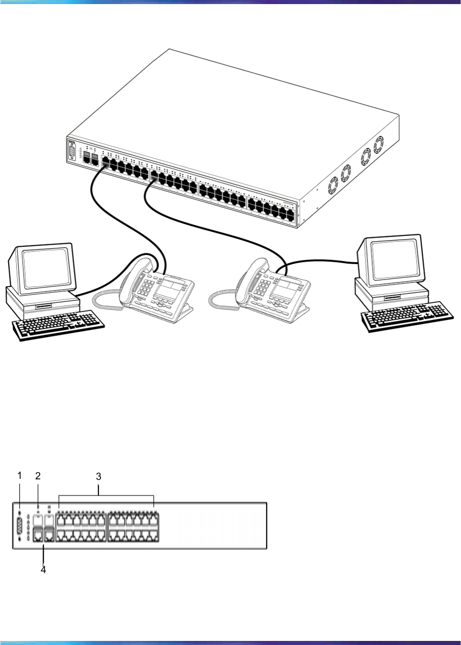
Figure 1 "Ethernet Routing Switch 2550T-PWR" (page 24) shows an
Ethernet Routing Switch 2550T-PWR providing power and Ethernet
connections to IP Phones, and data connections to personal computers
(PC).
Nortel Ethernet Routing Switch 2500 Series
Overview — System Configuration
NN47215-500 (323162-B) 02.02 Standard
4.1 19 November 2007
Copyright © 2007, Nortel Networks
.
24 Ethernet Routing Switch 2500 Series hardware
Figure 1
Ethernet Routing Switch 2550T-PWR
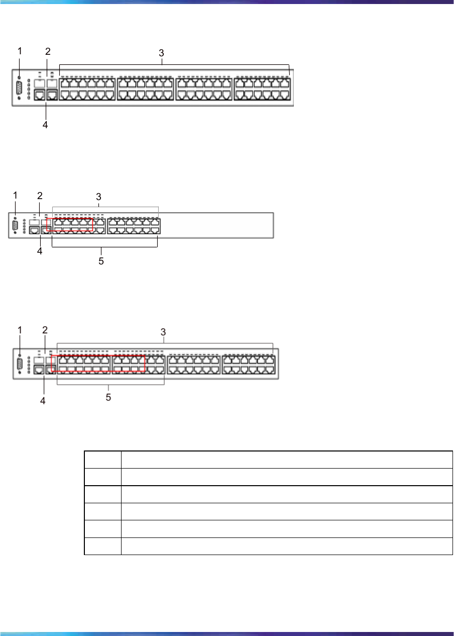
The following graphics display the front panel configuration on the Ethernet
Routing Switch 2526T, 2526T-PWR, 2550T, and 2550T-PWR. Table 1
"Components on the Ethernet Routing Switch 2500 front panel" (page
25) describes the components on the front panel.
Figure 2
Ethernet Routing Switch 2526T front panel
Nortel Ethernet Routing Switch 2500 Series
Overview — System Configuration
NN47215-500 (323162-B) 02.02 Standard
4.1 19 November 2007
Copyright © 2007, Nortel Networks
.
Hardware components of the Ethernet Routing Switch 2500 Series 25
Figure 3
Ethernet Routing Switch 2550T front panel
Figure 4
Ethernet Routing Switch 2526T-PWR front panel
Figure 5
Ethernet Routing Switch 2550T-PWR front panel
Table 1
Components on the Ethernet Routing Switch 2500 front panel
Item Description
1Console port
2SFP Gigabit Interface Converter (GBIC) slots
310/100BaseT RJ-45 connector ports (copper)
410/100/1000BaseT RJ-45 connector ports (copper)
5PoE ports (on 2526T-PWR and 2550T-PWR models only)
Console port
With the Console port, you can access the Command Line Interface (CLI)
commands to customize your network. For more information about using
the CLI, see "CLI Basics" (page 81).
Nortel Ethernet Routing Switch 2500 Series
Overview — System Configuration
NN47215-500 (323162-B) 02.02 Standard
4.1 19 November 2007
Copyright © 2007, Nortel Networks
.

26 Ethernet Routing Switch 2500 Series hardware
The Console port is a DB-9, RS-232-D male serial port connector. You can
use this connector to connect a management station, console, or terminal to
the Ethernet Routing Switch 2500 Series by using a straight-through DB-9
to DB-9 standard serial port cable. You must use a VT100/ANSI-compatible
terminal (for cursor control and to activate cursor and functions keys) to
use the Console port.
The default settings of the Console port are:
•9600 baud with eight data bits
•one stop bit
•no parity as the communications format
•flow control set to disabled
Gigabit Interface Converter
Small Form Factor Pluggable Gigabit Interface Converters are
hot-swappable input and output enhancement components designed for
use with Nortel products to allow Gigabit Ethernet ports to link with fiber
optic networks.
SFP GBIC Support on the Ethernet Routing Switch 2500 Series
Small Form Factor Pluggable (SFP) transceivers are hot-swappable
input/output enhancement components designed for use with Nortel
products to allow Gigabit Ethernet ports to link with other Gigabit Ethernet
ports over various media types.
The Ethernet Routing Switch 2500 Series supports the following SFPs:
•1000Base-SX SFP GBIC (mini-GBIC, connector type: LC)
•1000Base-SX SFP GBIC (mini-GBIC, connector type: MT-RJ)
•1000Base-LX SFP GBIC (mini-GBIC, connector type: LC)
•CWDM SFPs
For more information about the SFP GBICs see Installing Gigabit Interface
Converters, SFPs, and CWDM SFP Gigabit Interface Converters (312865).
Port connectors
The Ethernet Routing Switch 2500 Series uses 10BASE-T/100BASE-TX
RJ-45 (8-pin modular) port connectors.
The Ethernet Routing Switch 2500 Series uses autosensing ports
designed to operate at 10 Mb/s (megabits per second) or at 100 Mb/s,
depending on the connecting device. These ports support the IEEE 802.3u
autonegotiation standard, which means that when a port is connected
to another device that also supports the IEEE 802.3u standard, the two
devices negotiate the best speed and duplex mode.
Nortel Ethernet Routing Switch 2500 Series
Overview — System Configuration
NN47215-500 (323162-B) 02.02 Standard
4.1 19 November 2007
Copyright © 2007, Nortel Networks
.

Hardware components of the Ethernet Routing Switch 2500 Series 27
The 10BASE-T/100BASE-TX switch ports also support half- and full-duplex
mode operation.
The 10BASE-T/100BASE-TX RJ-45 switch ports can connect to 10 Mb/s or
100 Mb/s Ethernet segments or nodes.
ATTENTION
Use only Category 5 copper Unshielded Twisted Pair (UTP) cable connections
when connecting 10BASE-T/100BASE-TX ports.
Auto-MDI/MDI-X
The 10/100BASE-TX port connectors support auto-MDI/MDI-X.
Typical MDI-X ports connect over straight-through cables to the Network
Interface Card (NIC) in a node or server, similar to a conventional Ethernet
repeater hub. However, with the auto-MDI/MDI-X feature, you can still use
straight-through cables while connecting to an Ethernet hub or switch.
The auto-MDI/MDI-X feature is dependent on the autonegotiation feature.
If autonegotiation is enabled on a port, the auto-MDI/MDI-X feature is
automatically enabled on the port as well. If autonegotiation is disabled on a
port, then the port operates as a standard MDI-X port.
Power over Ethernet on Ethernet Routing Switch 2526T-PWR
and 2550T-PWR
The Ethernet Routing Switch 2526T-PWR and 2550T-PWR provide IEEE
802.3af-compliant power over the PoE-labeled front-panel RJ-45 ports. The
switches provide power discovery and power management on each port
basis. You can use the PoE ports to provide power to network appliances,
such as IP Phones, wireless access points, and video devices.
You can enable or disable power to individual ports. For information about
configuring PoE, see "Power over Ethernet for the Ethernet Routing Switch
2526T-PWR and 2550T-PWR" (page 157).
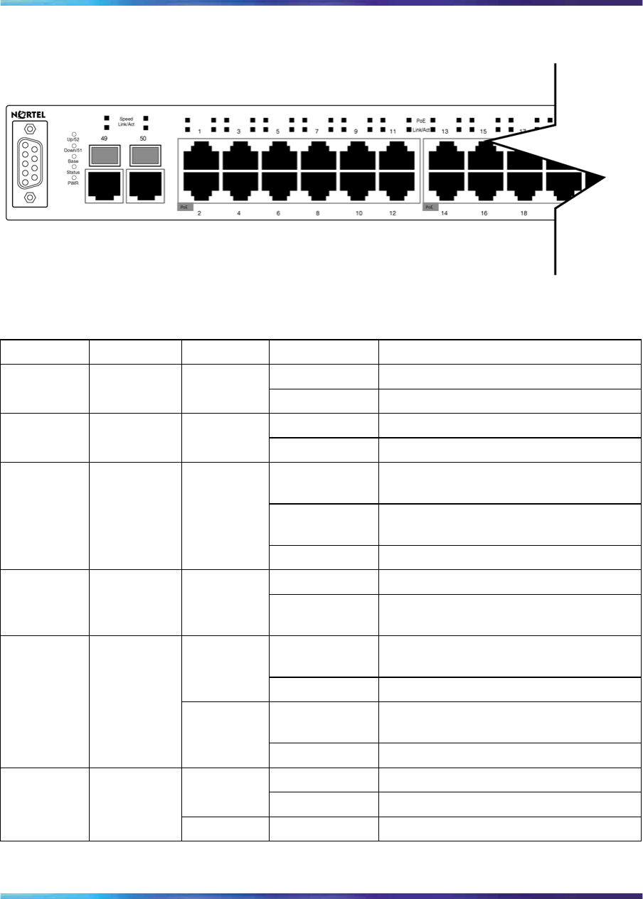
LED display panel
Figure 6 "LED display panel" (page 28) shows the LED display panel of the
Ethernet Routing Switch 2500 Series. See Table 2 "Ethernet Routing Switch
2500 Series LED descriptions" (page 28) for a description of the LEDs.
Nortel Ethernet Routing Switch 2500 Series
Overview — System Configuration
NN47215-500 (323162-B) 02.02 Standard
4.1 19 November 2007
Copyright © 2007, Nortel Networks
.
28 Ethernet Routing Switch 2500 Series hardware
Figure 6
LED display panel
Table 2
Ethernet Routing Switch 2500 Series LED descriptions
Label Type Color State Meaning
Fast Flashing Link is good and active.Up/28 or
Up/52 Rear port
status Green
Slow Flashing This port is disabled by software.
Fast Flashing Link is good and active.Down/27
Down/51 Rear port
status Green
Slow Flashing This port is disabled by software.
Flashing The switch is booting up and performing
a self-test.
On Self-test passed successfully and
switch is operational.
Status Switch
status Green
Off The switch failed the self-test.
On Power is present.PWR Switch Pow
er Status Green
Off Switch is not connected to a power
source.
Steady This port is set to operate at 1 Gb/s,
and the link is good.
Green
Flashing This port is disabled by software.
Steady This port is set to operate at 10/100
Mb/s, and the link is good.
Speed RJ45/SFP
Uplink port
speed
Amber
Flashing This port is disabled by software.
Steady Link is OK.
Green
Flashing Traffic activity.
Link/Act RJ45/SFP
Uplink port
status Off No link/No traffic.
Nortel Ethernet Routing Switch 2500 Series
Overview — System Configuration
NN47215-500 (323162-B) 02.02 Standard
4.1 19 November 2007
Copyright © 2007, Nortel Networks
.
Hardware components of the Ethernet Routing Switch 2500 Series 29
Label Type Color State Meaning
Steady Station connected at 10/100 Mb/s.Green
Flashing Traffic activity at 10/100 Mb/s.
Link/Act Port conne
ction status
Off No link/No traffic.
Green Steady Power is supplied to the port.PoE (applie
s to PWR
models
only)
PoE port
power
status Off No power is supplied to the port.
Green ON This unit is permanent base in stack
mode.
Base Base unit
status for
stack mode Amber ON This unit is selected as temporary base
in stack mode.
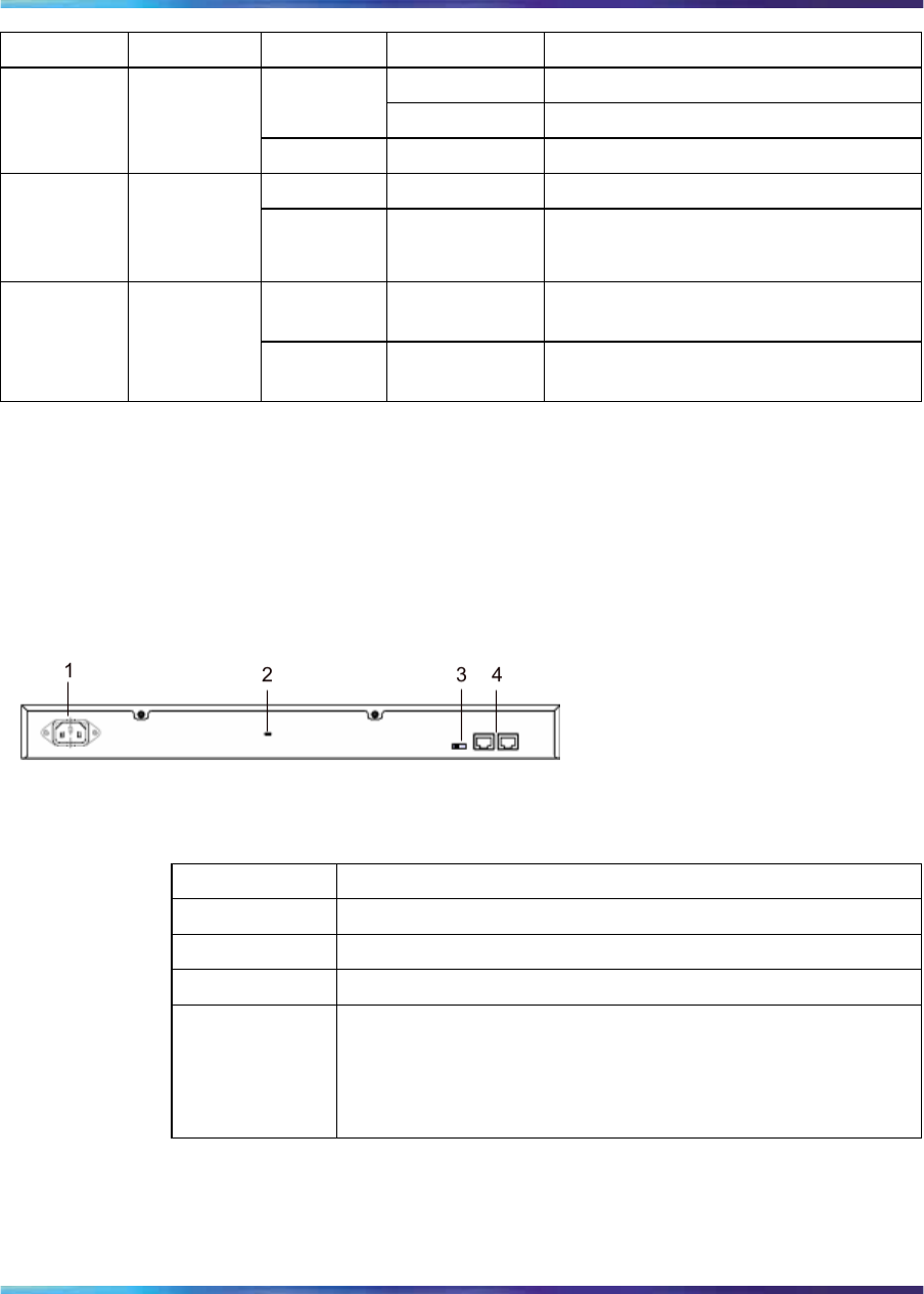
Back panel
The back panel of the Ethernet Routing Switch 2500 Series is shown in
Figure 7 " Ethernet Routing Switch 2500 Series back panel" (page 29).
Table 3 "Components on the Ethernet Routing Switch 2500 Series back
panel" (page 29) describes the components on the back panel.
Figure 7
Ethernet Routing Switch 2500 Series back panel
Table 3
Components on the Ethernet Routing Switch 2500 Series back panel
Item Description
1AC power receptacle
2Kensington lock
3Base Unit select switch
4Additional 1000BaseT RJ-45 connector rear ports.
For switch operating mode: ports 27,28 on 2526T models and
ports 51,52 on 2550T models.
For stack operating mode: Link UP, Link DOWN for connecting
with other units in stack.
Kensington lock
Using the Kensington lock, you can secure your switch. Wrap the steel cable
around a secure immovable object, insert the cable lock in the Kensington
Security Lock, and turn the key.
Nortel Ethernet Routing Switch 2500 Series
Overview — System Configuration
NN47215-500 (323162-B) 02.02 Standard
4.1 19 November 2007
Copyright © 2007, Nortel Networks
.
30 Ethernet Routing Switch 2500 Series hardware
Cooling fans
Cooling fans are located on one side of the Ethernet Routing Switch 2500
Series to provide cooling for the internal components. When you install
the switch, be sure to allow enough space on both sides of the switch for
adequate ventilation.
AC power receptacle
The AC power receptacle accepts the AC power cord that is supplied with
the switch. For installation outside North America, make sure that you
have the proper power cord for your region. Any cord used must have a
CEE-22 standard V female connector on one end and must meet the IEC
320-030 specifications.Table 4 "International power cord specifications"
(page 30) lists specifications for international power cords.
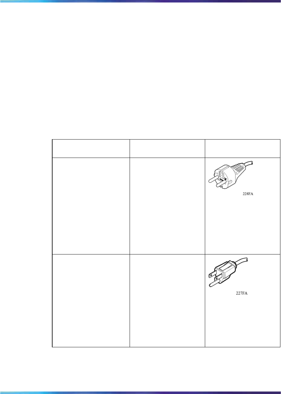
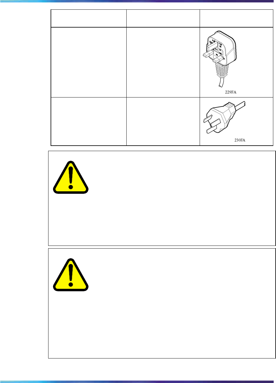
Table 4
International power cord specifications
Country/Plug
description Specifications Typical plug
Continental Europe:
•CEE7 standard VII
male plug
•Harmonized cord
(HAR marking on
the outside of the
cord jacket to comply
with the CENELEC
Harmonized
Document HD-21)
220 or 230 VAC 50 Hz
Single phase
U.S./Canada/Japan:
•NEMA5-15P male
plug
•UL recognized (UL
stamped on cord
jacket)
•CSA certified (CSA
label secured to the
cord)
100 or 120 VAC 50– 60
Hz Single phase
Nortel Ethernet Routing Switch 2500 Series
Overview — System Configuration
NN47215-500 (323162-B) 02.02 Standard
4.1 19 November 2007
Copyright © 2007, Nortel Networks
.
Hardware components of the Ethernet Routing Switch 2500 Series 31
Country/Plug
description Specifications Typical plug
United Kingdom:
•BS1363 male plug
with fuse
•Harmonized cord
240 VAC
50 Hz
Single phase
Australia:
AS3112-1981 Male plug
240 VAC
50 Hz
Single phase
CAUTION
Read immediately.
Inspect the power cord and determine if it provides the proper
plug and is appropriately certified for use with your electrical
system. Immediately discard this power cord if it is inappropriate
for electrical systems in your country and obtain the proper cord
as required by your national electrical codes or ordinances.
See the technical documentation for this product for detailed
installation procedures to be followed by qualified service
personnel.
CAUTION
Vorsicht:
Bitte sofort lesen.
Sehen Sie nach, ob dieses Netzkabel über den richtigen
Stecker verfügt und für die Verwendung in Ihrem
Stromversogungsnetz zertifiziert ist. Falls dieses Kabel nicht für
das Stromversorgungsnetz in Ihrem Land geeignet ist, darf es
nicht verwendet werden. Besorgen Sie sich ein Kabel, das die
Vorschriften der Zulassungsbehörden in Ihrem Land erfüllt.
Die technische Dokumentation dieses Produkts enthält
ausführliche Installationsanweisungen, die nur von qualifiziertem
Kundendienstpersonal ausgeführt werden dürfen.
Nortel Ethernet Routing Switch 2500 Series
Overview — System Configuration
NN47215-500 (323162-B) 02.02 Standard
4.1 19 November 2007
Copyright © 2007, Nortel Networks
.
32 Ethernet Routing Switch 2500 Series hardware
ATTENTION
Attention:
Lisez ceci immédiatement.
Examinez ce cordon d’alimentation pour déterminer s’il dispose de la fiche
appropriée et s’il est bien agréé pour utilisation sur votre installation électrique.
Débarrassez-vous en immédiatement s’il ne convient pas à l’utilisation sur
le secteur électrique en usage dans votre pays et procurez-vous un cordon
conforme à la réglementation nationale en vigueur.
Reportez-vous à la documentation technique de ce produit pour obtenir des
instructions détaillées d’installation, destinées à un technicien qualifié.
CAUTION
Attenzione:
Leggere attentamente.
Controllare questo cavo di alimentazione, verificarne il
collegamento con la presa appropriata nonché la certificazione
per l’uso nell’impianto elettrico posseduto. Non utilizzare
assolutamente in caso tale cavo non sia adatto al sistema elettrico
del paese in cui viene utilizzato e richiederne un altro certificato
dall’ente nazionale di fornitura elettrica.
Per le procedure di installazione che devono essere seguite dal
personale di servizio, consultare questa documentazione tecnica
del prodotto.
CAUTION
Advertencia:
Sírvase leer inmediatamente.
Inspeccione este cable de alimentación eléctrica y determine si
viene con el enchufe apropiado y está debidamente certificado
para el uso con su sistema eléctrico. Si no cumple con los
reglamentos del sistema eléctrico de su país, despójese de
este cable de alimentación inmediatamente y obtenga el cable
requerido, según las ordenanzas y códigos eléctricos nacionales.
Refiérase a la documentación técnica de este producto para
recibir información detallada sobre los procedimientos que el
personal calificado de reparaciones deberá seguir.
Nortel Ethernet Routing Switch 2500 Series
Overview — System Configuration
NN47215-500 (323162-B) 02.02 Standard
4.1 19 November 2007
Copyright © 2007, Nortel Networks
.
Hardware components of the Ethernet Routing Switch 2500 Series 33
WARNING
Removal of the power cord is the only way to turn off power to this
device. The power cord must always be connected in a location
that can be accessed quickly and safely in case of an emergency.
WARNING
Vorsicht:
Die Stromzufuhr zu diesem Gerät kann nur durch Ziehen des
Netzstromkabels unterbrochen werden. Die Netzsteckdose, an
die das Netzstromkabel angeschlossen ist, muß sich stets an
einem Ort befinden, der bei einem Notfall schnell und einfach
zugänglich ist.
WARNING
Avertissement:
Le débranchement du cordon d’alimentation constitue le
seul moyen de mettre cet appareil hors tension. Le cordon
d’alimentation doit donc toujours être branché dans une prise
accessible pour faciliter la mise hors tension en cas d’urgence.
WARNING
Advertencia:
La única forma de desconectar la alimentación de este dispositivo
es desenchufar el cable de alimentación. El cable de alimentación
siempre debe estar conectado en una ubicación que permita
acceder al cable de forma rápida y segura en caso de emergencia.
Nortel Ethernet Routing Switch 2500 Series
Overview — System Configuration
NN47215-500 (323162-B) 02.02 Standard
4.1 19 November 2007
Copyright © 2007, Nortel Networks
.
34 Ethernet Routing Switch 2500 Series hardware
WARNING
Avvertenza:
Estrarre il cavo di alimentazione è l’unico sistema per spegnere il
dispositivo. Il cavo di alimentazione deve essere sempre collegato
in una posizione che permetta l’accesso facile e sicuro in caso
di emergenza.
Network configuration examples
This section provides network configuration examples using the Ethernet
Routing Switch 2500 Series switches. In these examples, traffic Quality of
service (QoS) feature can be used to prioritize the traffic of the network to
ensure uninterrupted traffic of critical applications. The examples are:
•"Small office desktop switch application" (page 34)
•"Branch office workgroup switch application" (page 35)
•"Medium sized office wiring closet switch application" (page 36)
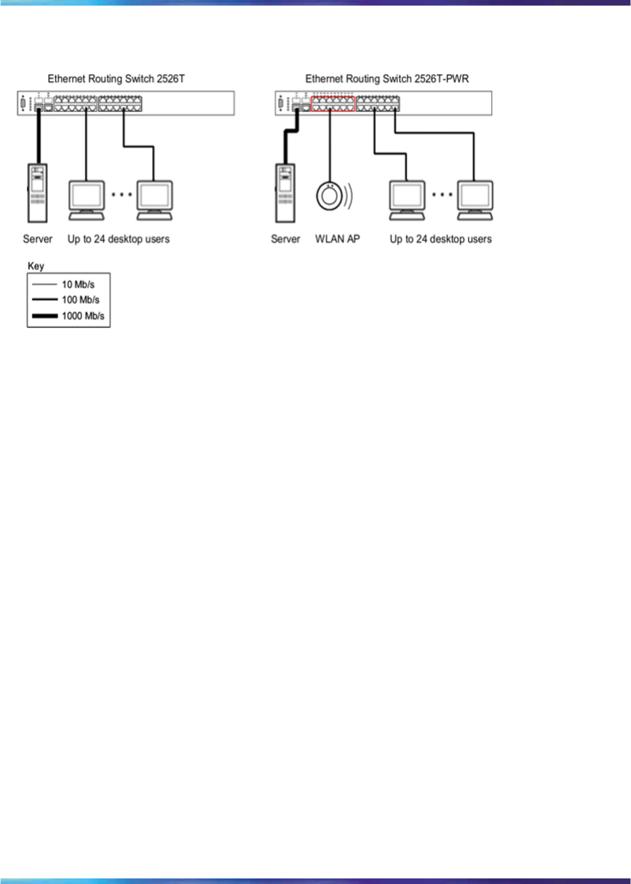
Small office desktop switch application
Figure 8 "Ethernet Routing Switch 2500 Series used as a desktop switch"
(page 35) shows the Ethernet Routing Switch 2500 Series used as a
desktop switch in a small office environment. The desktop workstations and
servers are connected directly to the switch ports. Alternatively, an ERS
2500 series switch that supports Power over Ethernet (PoE) can provide
connectivity and power to Wireless LAN Access Points (WLAN APs) in
addition to desktop workstations and servers.
Nortel Ethernet Routing Switch 2500 Series
Overview — System Configuration
NN47215-500 (323162-B) 02.02 Standard
4.1 19 November 2007
Copyright © 2007, Nortel Networks
.
Network configuration examples 35
Figure 8
Ethernet Routing Switch 2500 Series used as a desktop switch
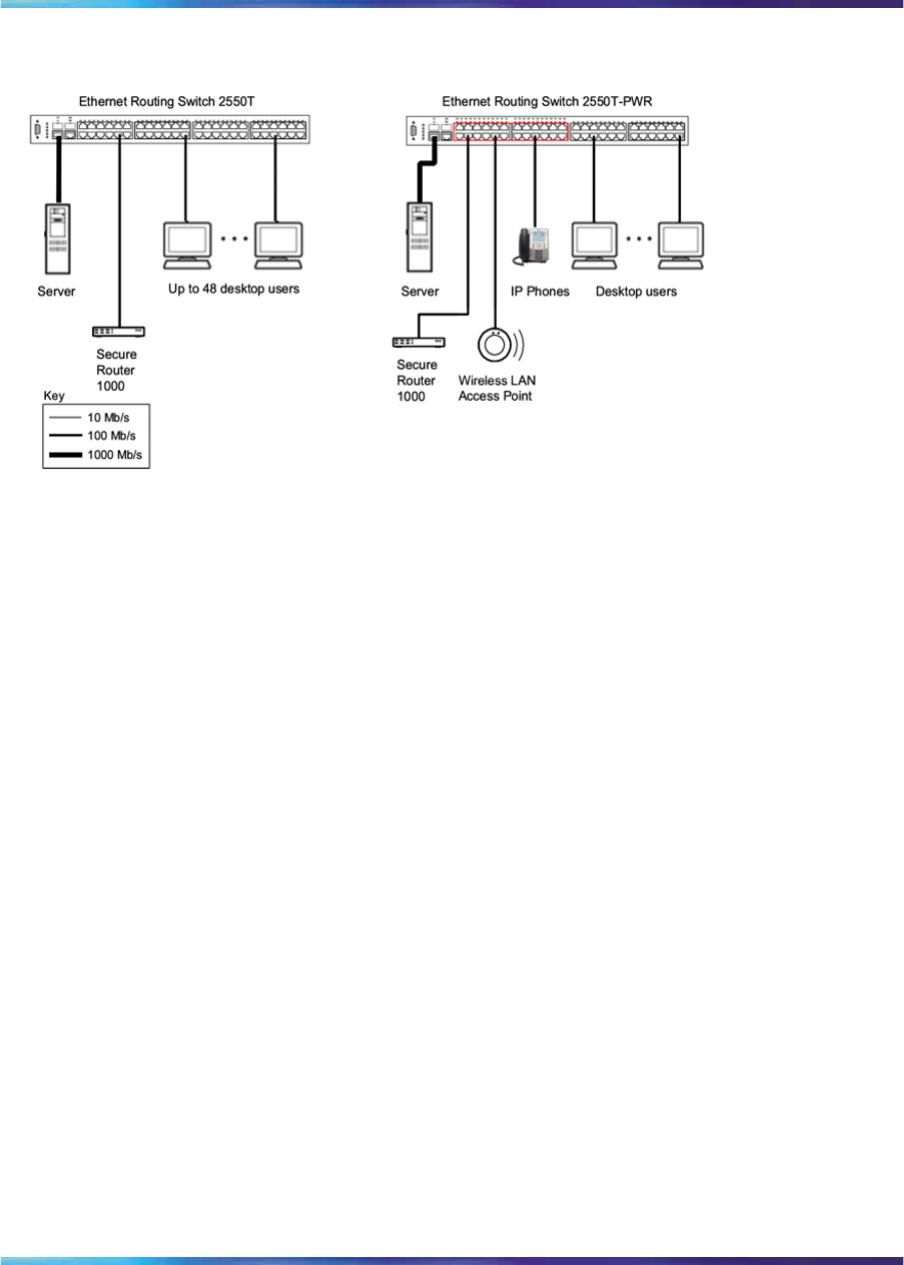
Branch office workgroup switch application
Figure 9 "Ethernet Routing Switch 2500 Series used as a workgroup
switch" (page 36) shows the Ethernet Routing Switch 2500 Series used as
a workgroup switch in an enterprise branch office environment. Desktop
workstations and servers are connected directly to the switch ports.
Alternatively, an ERS 2500 series switch that supports Power over Ethernet
(PoE) can provide connectivity and power to IP Phones and Wireless LAN
Access Points (WLAN APs) in addition to desktop workstations and servers.
The Ethernet Routing Switch 2500 series switch can optionally be stacked
up to 8 units to form a single virtual switch providing up to 384 10/100Mb/s
connections and 16 1000Mb/s connections.
Nortel Ethernet Routing Switch 2500 Series
Overview — System Configuration
NN47215-500 (323162-B) 02.02 Standard
4.1 19 November 2007
Copyright © 2007, Nortel Networks
.
36 Ethernet Routing Switch 2500 Series hardware
Figure 9
Ethernet Routing Switch 2500 Series used as a workgroup switch
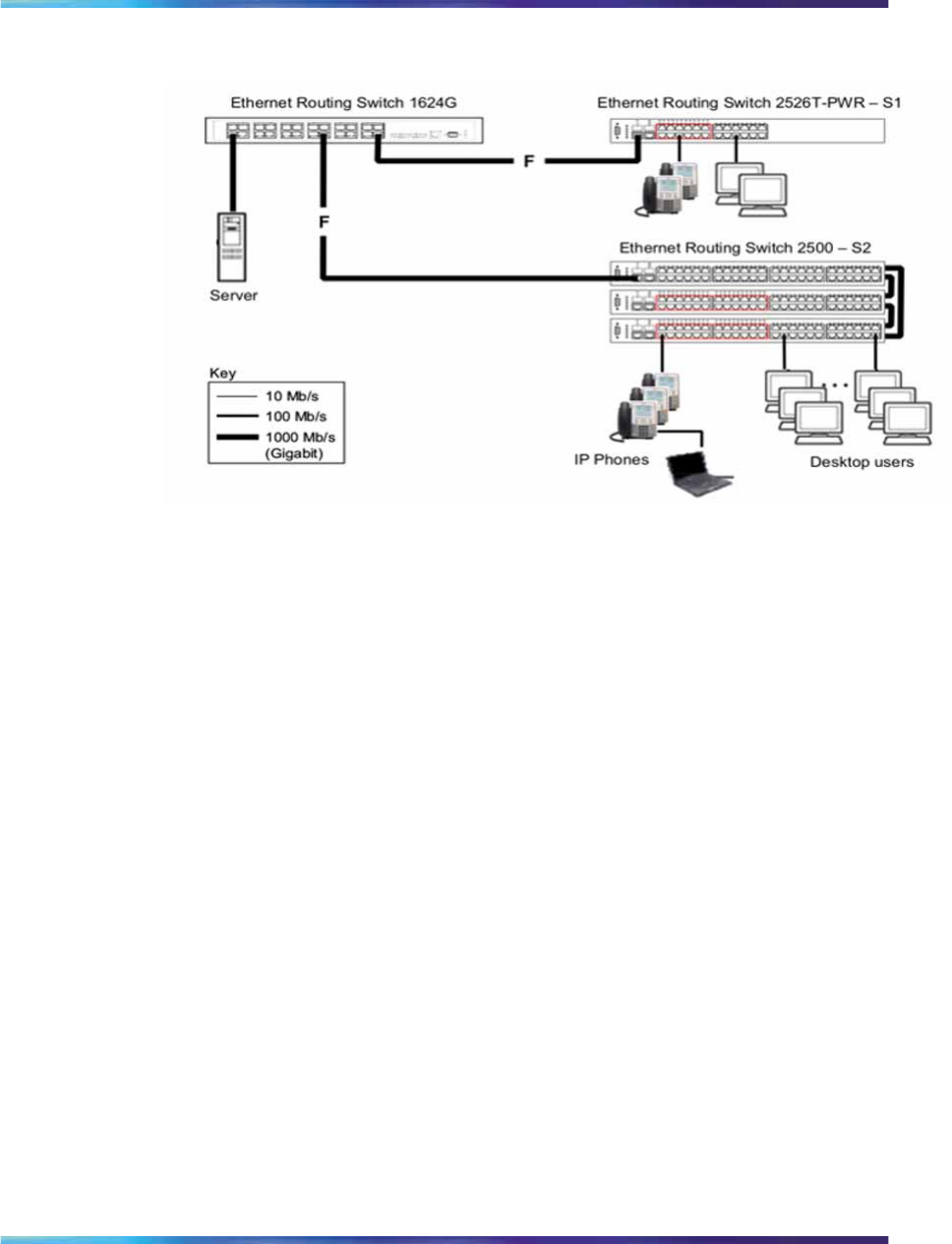
Medium sized office wiring closet switch application
Figure 10 "Configuring power workgroups and a wiring closet switch" (page
37) shows the Ethernet Routing Switch 2500 series used as a wiring
closet switch in a medium to large enterprise office environment. Desktop
workstations, IP Phones, and WLAN APs are connected directly to the
switch ports.
Figure 10 "Configuring power workgroups and a wiring closet switch"
(page 37) shows the Ethernet Routing Switch 1600 series used as a
backbone switch, connecting to Ethernet Routing Switch 2500 – S1, with
an optional 1000BASE-SX SFP GBIC for maximum bandwidth. S2 is a
single virtual switch stack of three ERS 2500 switches providing 10 or
100Mb/s, also connecting to the ERS 1624G backbone switch with an
optional 1000BASE-SX SFP GBIC in both switches.
Nortel Ethernet Routing Switch 2500 Series
Overview — System Configuration
NN47215-500 (323162-B) 02.02 Standard
4.1 19 November 2007
Copyright © 2007, Nortel Networks
.
Network configuration examples 37
Figure 10
Configuring power workgroups and a wiring closet switch
Nortel Ethernet Routing Switch 2500 Series
Overview — System Configuration
NN47215-500 (323162-B) 02.02 Standard
4.1 19 November 2007
Copyright © 2007, Nortel Networks
.

38 Ethernet Routing Switch 2500 Series hardware
Nortel Ethernet Routing Switch 2500 Series
Overview — System Configuration
NN47215-500 (323162-B) 02.02 Standard
4.1 19 November 2007
Copyright © 2007, Nortel Networks
.

39
Nortel Ethernet Routing Switch 2500
Series stacking
This chapter includes information about the stacking features, such as stack
capabilities, stacking functionality delivery, stack configuration, and Auto Unit
Replacement. This chapter contains information about the following topics:
•"Stacking capabilities" (page 39)
•"Stacking functionality delivery" (page 40)
•"Stack configuration" (page 45)
•"Auto Unit Replacement" (page 54)
Stacking capabilities
The Nortel Ethernet Routing Switch 2500 Series contain two built-in rear
ports that can be used as stacking/cascade ports to enable a stack of up to
eight units.
A stack can consist of Nortel Ethernet Routing Switch 2526T, Nortel Ethernet
Routing Switch 2550T, Nortel Ethernet Routing Switch 2526T-PWR, and
Nortel Ethernet Routing Switch 2550T-PWR units.
The stack ports on ERS 2500 series switches provide 4Gbps (FDX) stack
bandwidth for an aggregate of up to 32Gbps for a stack of eight units.
A stack of Ethernet Routing Switch 2500 series switches can also consist of
a mix of stack pre-enabled units as well as non pre-enabled units. The non
pre-enabled units in a stack must meet the following requirements before
they are added into a stack configuration:
•contain a valid license file (a license file contains the switch MAC
addresses)
•Operational mode of rear ports operating in Stacking Mode
Nortel Ethernet Routing Switch 2500 Series
Overview — System Configuration
NN47215-500 (323162-B) 02.02 Standard
4.1 19 November 2007
Copyright © 2007, Nortel Networks
.

40 Nortel Ethernet Routing Switch 2500 Series stacking
Stacking functionality delivery
The Nortel Ethernet Routing Switch 2500 series switches allow you to
stack multiple switches together to create a single virtual switch that can
be managed as a single device. Stacking functionality is delivered in
two distinctively different ways on Ethernet Routing Switch 2500 series
switches:
•Through stack enabled units with order codes AL2515xxx-E6. The
rear ports of stack enabled ERS 2500 switch are factory pre-enabled,
configured, and operating in Stacking Mode by default and are ready
to stack. These units do not require or use the software licensing
mechanism.
•Through software using a licensing mechanism for standalone units with
order codes AL2500xxx-E6. Standalone ERS 2500 switches require the
purchase of a Stacking License Kit for each license to create a license
file, which unlocks stacking capability on standalone units.
Stack enabled switches
The stack enabled unit rear ports are configured in Stacking Mode at
the factory and are ready for immediate use for connection in a stack
configuration. Stacking Mode is the default operating mode that cannot be
overridden by a factory default. Standalone Mode operation is still available
for configuration on the rear-ports of stack enabled units. For information
on adding or replacing a new unit, see "Adding/Replacing a stack unit"
(page 53).
All factory pre-enabled units are identifiable through CLI, Web UI, and
Device Manager with the text Stack Enabled included in the switch
description for identification purposes.
Standalone configuration with license files
Standalone units are not pre-enabled with stacking capability in the factory
and require the use of a software based licensing mechanism to unlock
stacking functionality for activation on the rear ports. Standalone units use
the GenLic engine for decryption of a license file. The license file must
contain the switch MAC address to unlock the stacking functionality.
Standalone units require the purchase of an Ethernet Routing Switch 2500
series Stacking License Kit, of which there are four types available. Each kit
contains a License Certificate with a License Authorization Code (LAC) that
enables a specific number of stacking licenses for one or multiple ERS 2500
series switches. Each ERS 2500 series switch requires one license file to
unlock stacking functionality. A single license file can contain up to 1000
switch MAC addresses for installation on multiple switches.
Nortel Ethernet Routing Switch 2500 Series
Overview — System Configuration
NN47215-500 (323162-B) 02.02 Standard
4.1 19 November 2007
Copyright © 2007, Nortel Networks
.

Stacking functionality delivery 41
A Stacking License Certificate contains instructions on how to deposit
license entitlements into a license bank, enter switch MAC address(es),
create the license file, then download and copy the license file onto each
switch requiring stacking functionality. These instructions are carried out on
the Nortel Licensing portal web site at: www.nortellicensing.com.
ATTENTION
Once a valid license file is downloaded on to an Nortel Ethernet Routing Switch
2500 Series switch, you can configure the operational mode of rear ports to
Stacking Mode. Although the rear ports are set to Stacking Mode, a reboot of the
switch is required to fully enable the stacking operation.
Working with license files using the CLI
With the following commands, you can copy the license file to your switch
and display or clear the existing license information:
•"copy tftp license command" (page 41)
•"show license command" (page 42)
•"clear license command" (page 42)
copy tftp license command The copy tftp license command
copies the license file from a TFTP server to your switch. After you copy the
license to the switch, you need to perform a reboot to activate the license.
ATTENTION
The license is copied to NVRAM. If you reset the switch to default, this removes
the license from the switch. But the stacking feature is enabled until you configure
the switch to Standalone Mode.
The syntax for the copy tftp license command is:
copy tftp license <A.B.C.D> <WORD>
The copy tftp license command is executed in the Privileged EXEC
command mode.
"copy tftp license command parameters" (page 41) describes the
parameters and variables for the copy tftp license command.
copy tftp license command parameters
Parameters and
variables Description
<A.B.C.D> The TFTP server address.
<WORD> The software license filename on the TFTP server.
Nortel Ethernet Routing Switch 2500 Series
Overview — System Configuration
NN47215-500 (323162-B) 02.02 Standard
4.1 19 November 2007
Copyright © 2007, Nortel Networks
.
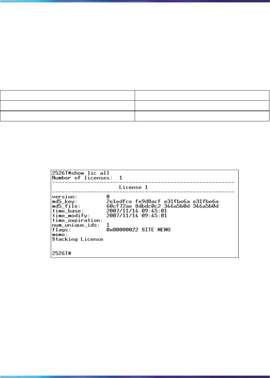
42 Nortel Ethernet Routing Switch 2500 Series stacking
show license command The show license command displays the
existing licenses on your switch. The syntax for the show license
command is:
show license { <1-10> | all }
The show license command is executed in the Privileged EXEC
command mode.
Table 5
show license command parameters
Parameters and variables Description
<1-10> Displays the selected licenses.
all Displays all licenses.
The following figure displays a sample output for the show license all
command after installing the license file.
Figure 11
show license all command output
clear license command The clear license command deletes the
existing licenses on your switch.
The syntax for the clear license command is:
clear license { <1-10> | all }
The clear license command is executed in the Privileged EXEC
command mode.
Copying the license file using the Java Device Manager
Use the Java Device Manager to copy the license file to the 2500 Series
Nortel Ethernet Routing Switch.
Nortel Ethernet Routing Switch 2500 Series
Overview — System Configuration
NN47215-500 (323162-B) 02.02 Standard
4.1 19 November 2007
Copyright © 2007, Nortel Networks
.
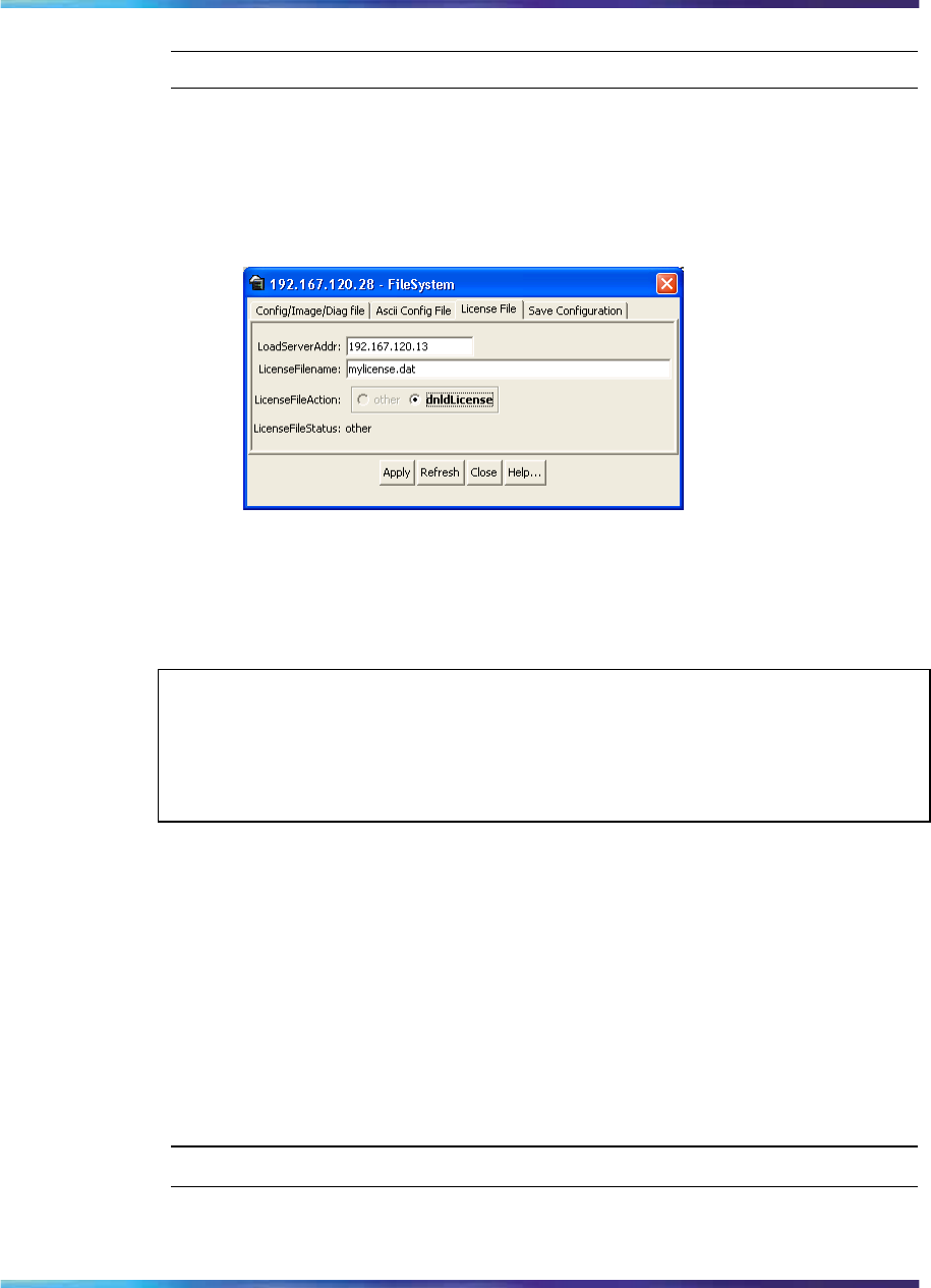
Stacking functionality delivery 43
Step Action
1From the Device Manager menu select Edit > File System.
The FileSystem dialog box appears.
2Click the License File tab.
The License File tab appears.
3In the LoadServerAddr field, enter the TFTP server address.
4In the LicenseFileName field, enter the software license filename
on the TFTP server.
ATTENTION
The LicenseFileName field is case sensitive and you can use a maximum
of 64 characters including the file extension. Numerals are allowed in the
LicenseFileName but special characters like @, -, #, and so on are not allowed.
5In the LicenseFileAction field, select dnldLicense.
6Click Apply.
7Click Refresh.
The LicenseFileStatus field displays the file copy progress. After
the file copy completes, a warning message appears prompting you
to reboot the switch and activate the license.
8To reboot the switch, choose Edit > Chassis
9Under the System tab, select the reboot option and click Apply.
—End—
Nortel Ethernet Routing Switch 2500 Series
Overview — System Configuration
NN47215-500 (323162-B) 02.02 Standard
4.1 19 November 2007
Copyright © 2007, Nortel Networks
.
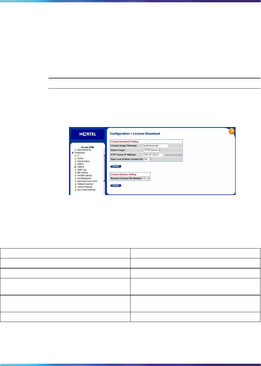
44 Nortel Ethernet Routing Switch 2500 Series stacking
Downloading the license files using the Web-based management
interface
You can download the license files to the Nortel Ethernet Routing Switch. To
download the Ethernet Routing Switch 2500 Series license files, a properly
configured Trivial File Transfer Protocol (TFTP) server must be present in
your network, and the Ethernet Routing Switch 2500 Series must have an
IP address.
To download a license file, use the following procedure:
Step Action
1From the main menu, choose Configuration > License Download.
The License Download page appears.
Figure 12
License Download page
The following table describes the fields on the License Download
page.
Table 6
License Download page fields
Fields Description
License Image Filename Type the valid license image filename.
Select Target Choose the target address.
TFTP Server IP Address Type the IP address of your TFTP download
host.
Start Load of New License File Choose Yes to start downloading the new license
file immediately and No to cancel.
Remove License File Number Choose the license number to be removed.
2Type information in the text boxes, or select from a list.
3Click Submit.
Nortel Ethernet Routing Switch 2500 Series
Overview — System Configuration
NN47215-500 (323162-B) 02.02 Standard
4.1 19 November 2007
Copyright © 2007, Nortel Networks
.

Stack configuration 45
—End—
Stack configuration
The Nortel Ethernet Routing Switch 2500 series provides the capability for
intelligent fail-safe resilient stacking of up to eight units in a single switch
stack. This provides uninterrupted connectivity of up to 400 user ports in a
virtual switch managed as a single unit.
ATTENTION
All ERS 2500 series switches must be running software release 4.1 before being
connected in a stack configuration.
To set up a stack, do the following:
Step Action
1Power down all switches.
2Set the Unit Select switch at the rear of the non-base units to the
off position.
3Plug all stack cables in to the rear RJ-45 cascade ports and ensure
the cables are connected from Cascade Down on the first unit to
Cascade Up on the second unit and so on. The last unit in the stack
must be connected back to the first unit for full stack resiliency.
Ensure all the cascade cables are properly connected.
4Power up all the switches in the stack starting with the Base unit.
ATTENTION
In a mixed stack of 2526T, 2526T-PWR, 2550T, and 2550T-PWR, any
switch can act as the Base unit.
—End—
ATTENTION
The rear ports must be operating Stacking Mode before adding a switch into
a stack.
Nortel Ethernet Routing Switch 2500 Series
Overview — System Configuration
NN47215-500 (323162-B) 02.02 Standard
4.1 19 November 2007
Copyright © 2007, Nortel Networks
.

46 Nortel Ethernet Routing Switch 2500 Series stacking
Configuring the operational mode on rear ports using the CLI
You can use the following commands to configure the operational mode of
rear ports into Stacking or Standalone Mode:
•"rear-ports mode command" (page 46)
•"show rear-ports mode command" (page 46)
rear-ports mode command
The rear-ports mode command configures the operational mode of
the rear-port.
The syntax for the rear-ports mode is:
# rear-ports mode [unit <1-8>] {standalone|stacking}
The rear-ports mode command is executed in the Global Configuration
command mode.
Table 7 "rear-ports mode command" (page 46) describes the parameters
and variables for the rear-ports mode command.
Table 7
rear-ports mode command
Parameters and variables Description
[unit <1-8>] Specifies the unit number. You can use a
maximum of eight units.
{standalone|stacking} Specifies the operational mode of the selected
unit.
show rear-ports mode command
The show rear-ports mode displays the operational mode of the rear
port.
The syntax for the show rear-ports mode is:
# show rear-ports mode
The show rear-ports mode command is executed in Global
Configuration command mode in the CLI. There are no parameters and
variables for show rear-ports mode command.
Figure 13 "show rear-ports mode command output" (page 47) displays a
sample output of the show rear-ports mode command when the rear
ports are set and running in Stacking Mode.
Nortel Ethernet Routing Switch 2500 Series
Overview — System Configuration
NN47215-500 (323162-B) 02.02 Standard
4.1 19 November 2007
Copyright © 2007, Nortel Networks
.
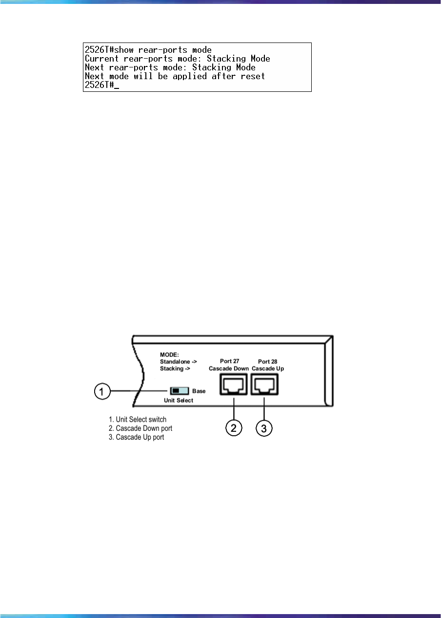
Stack configuration 47
Figure 13
show rear-ports mode command output
Configuring the operational mode of rear ports using the Device
Manager
Use the Device Manager to configure the operational mode of the rear ports
into Standalone or Stacking Mode in the Ethernet Routing Switch 2500
Series. For more information on configuring the operational mode of rear
ports, see "Rear Ports Mode tab" (page 252)
Rear ports and stacking
The rear panel view of a Nortel Ethernet Routing Switch 2500 series
switch consists of two RJ-45 1000BaseT ports and a Unit Select switch. In
Stacking Mode, the two rear ports become the Cascade Down and Cascade
Up ports for connecting switch units in a stack configuration. The rear panel
components are illustrated in the following diagram:
Figure 14
Rear panel components
Unit Select switch
The Unit Select switch is used to designate a switch in the stack as the
base unit. Sliding the switch to the right designates that switch as the base
unit. Only one switch in a stack has the Unit Select switch in the base unit
position. All other switches in the stack must have the Unit Select switch in
the left position.
The base unit designation of a switch is also displayed on the front panel
LED display. For more information, see Table 2 "Ethernet Routing Switch
2500 Series LED descriptions" (page 28)
Nortel Ethernet Routing Switch 2500 Series
Overview — System Configuration
NN47215-500 (323162-B) 02.02 Standard
4.1 19 November 2007
Copyright © 2007, Nortel Networks
.
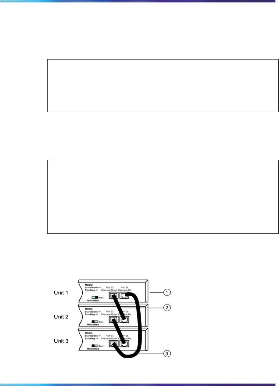
48 Nortel Ethernet Routing Switch 2500 Series stacking
Cascade Down port
The Cascade Down port is used to connect this switch unit to the next unit
in the stack through a stack cable. A connection from this port must be
attached to the Cascade Up port of the next switch in the stack. A return
cable from the Cascade Down port of the last unit must be connected to
the Cascade Up port of the first unit to complete the stack connection.
ATTENTION
Each Nortel Ethernet Routing Switch 2500 series switch is supplied with one
46-cm stack cable to create a stack connection. For stacking three or more units
(maximum 8 units per stack), you need to order the 1.5 or 3 meters stack return
cable (order number AL2518002-E6 and AL2518003-E6, respectively).
Cascade Up port
The Cascade Up port is used to accept a stack cable connection from
an adjacent unit above. A return cable from the Cascade Up port of the
first unit must be connected to the Cascade Down port of the last unit to
complete a stack connection.
ATTENTION
Nortel Ethernet Routing Switch 2500 series switches use tested and certified
Category 5E UTP cables as stack cables. All Nortel branded ERS 2500 series
stack cables are for use with these switches. However, Cat 5E stack cable
connections of up to 100 meters is possible between each ERS 2500 switch but
not officially supported. Using non-Nortel tested and certified stack cables for
such configurations are solely the user’s responsibility should any stack operation
issues occur.
The following illustration demonstrates the proper stack cable crossover
configuration. Failure to use this configuration can result in loss of
connectivity. This example shows a cascade down configuration
Connecting stack cables
Nortel Ethernet Routing Switch 2500 Series
Overview — System Configuration
NN47215-500 (323162-B) 02.02 Standard
4.1 19 November 2007
Copyright © 2007, Nortel Networks
.

Stack configuration 49
1. Base Unit
2. Cascade Cable
3. Cascade Cable (used for return)
Initial stack installation
During the initial installation of the stack, the software automatically
determines the physical order of all units in the stack according to the
position of the base unit within the stack. Thereafter, the individual units
maintain their original unit numbering, even if the position of one or more
units in the stack is changed.
For example, when the stack is initially powered, the base unit becomes unit
1 and the unit that the base unit connects to (via the Cascade Down cable)
becomes unit 2 (and the next unit is unit 3 and so on), until the maximum
stack configuration (up to 8 units) is reached. If the base unit is changed to
another unit in the stack, the new base unit keeps its original unit number
in the stack.
Stack MAC address
When a switch participates in a stack configuration, a stack MAC address is
automatically assigned during stack initialization. The stack MAC address is
the base unit MAC address plus 1. If another unit in the stack is assigned
as the base unit, the new stack MAC address is the MAC address of the
new base unit plus 1. The original stack IP address still applies to the new
base unit.
Stack configurations
Due to stack parameters being associated with the base unit, the physical
stack order depends on the base unit position and whether the stack is
configured cascade up (stack up) or cascade down (stack down). This
designation depends on the stack cabling arrangement.
The system automatically numbers the physical units based on the
designated base unit (Unit 1). In a cascade down configuration, the base
unit is physically located as the top unit in the stack. The cable connected to
the Cascade Down connector of the base unit terminates in the Cascade Up
connector on the next unit in the stack which is physically located below the
base unit. This next unit is designated Unit 2. The stack is wired downward
through the units and the system continues to number in this manner
throughout the stack. In this configuration, the base unit discovers the
stack in a cascade down (stack down) direction. The following illustration
demonstrates a cascade down (stack down) configuration.
Nortel Ethernet Routing Switch 2500 Series
Overview — System Configuration
NN47215-500 (323162-B) 02.02 Standard
4.1 19 November 2007
Copyright © 2007, Nortel Networks
.
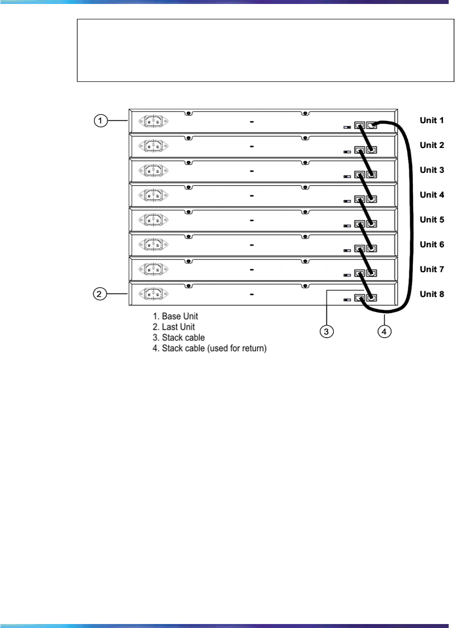
50 Nortel Ethernet Routing Switch 2500 Series stacking
ATTENTION
Many network management software packages assume a cascade down (stack
down) configuration, Nortel recommends the usage of this configuration.
Cascade down stack configuration
In a cascade up (stack up) configuration, the base unit is physically
located as the top unit in the stack. The cable connected to the Cascade
Down connector of the base unit terminates in the Cascade Up connector
physically located at the bottom of the stack. This next unit is designated Unit
2. The stack is wired upward through the units and the system continues to
number in this manner throughout the stack. In this configuration, the base
unit discovers the stack in a cascade up (stack up) direction. The following
illustration demonstrates a cascade up (stack up) configuration.
Nortel Ethernet Routing Switch 2500 Series
Overview — System Configuration
NN47215-500 (323162-B) 02.02 Standard
4.1 19 November 2007
Copyright © 2007, Nortel Networks
.
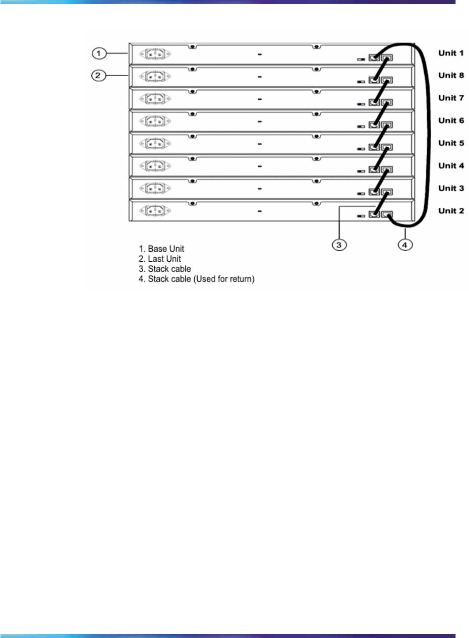
Stack configuration 51
Cascade up stack configuration
Regardless of stack configuration, the following applies:
•When power is applied to the stack the base unit initializes, typically
within 60 seconds, and the entire stack powers up as a single logical unit.
•A RS-232 communications cable can be attached to the console port of
any switch in the stack to establish a console connection.
•A software upgrade can be performed on the stack from any switch using
the console interface, a Telnet session, the web-based management
interface, or any SNMP-based management software.
•The stack can be managed using a Telnet session, web-based
management interface, or any SNMP-based management software
through any stack switch port.
•When stacking two or more switches. use the 3 meters cascade
max-return cable (part number AL2518003-E6) to complete the link
from the last unit in the stack to the base unit.
Temporary base unit
If an assigned base unit fails, the next unit in the stack order automatically
becomes the new temporary base unit. This change is indicated by the
Base LED on the temporary base unit LED display panel moving to a steady
amber state.
Nortel Ethernet Routing Switch 2500 Series
Overview — System Configuration
NN47215-500 (323162-B) 02.02 Standard
4.1 19 November 2007
Copyright © 2007, Nortel Networks
.

52 Nortel Ethernet Routing Switch 2500 Series stacking
This automatic failover is only a temporary safeguard. If the stack
configuration loses power, the temporary base unit cannot power up as
the base unit when power is restored. Also, if the original unit rejoins the
stack, it cannot resume base unit status. For this reason, always assign
the temporary base unit as the base unit until the failed unit is repaired
or replaced.
ATTENTION
If the temporary base unit is not assigned as the new base unit, and the temporary
base unit fails, the next unit in the stack order becomes the temporary base
unit. This process continues after successive failures until only two units are left
in the stack.
Redundant cascade stacking
The Nortel Ethernet Routing Switch 2500 Series allows a stack of up to 8
units into a dual-path cascade stack. If any single unit fails or if a cable is
accidently disconnected, other units in the stack remain operational without
interruption.
In addition to increasing bandwidth, the software uses the cables to provide
two paths between units. If one path breaks the data travels over the
remaining path with half the normal inter-switch bandwidth.
The following diagram shows an example of a stack configuration with a unit
failure in the stack. This illustrates:
•Unit 3 becomes non-operational due to a unit failure, cable
disconnection, or a loss of power.
•Units 2 and 4, directly upstream and downstream from Unit 3, sense
the loss of link signals from unit 3. The software causes all the data to
traverse the remaining path.
•The Cascade Down LED for Unit 2 and the Cascade Up LED for Unit 4
turn amber to indicate an error has been detected.
•The remaining stack units continue to be connected.
Nortel Ethernet Routing Switch 2500 Series
Overview — System Configuration
NN47215-500 (323162-B) 02.02 Standard
4.1 19 November 2007
Copyright © 2007, Nortel Networks
.
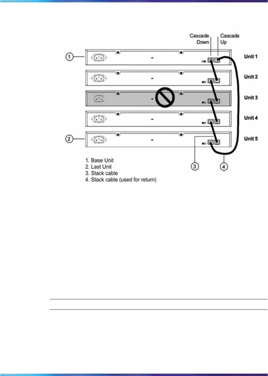
Stack configuration 53
Redundant cascade stacking
Removing a stack unit
If a unit is removed from the stack, the following switch configuration settings
revert to those configured before the unit became a member of the stack:
•IP address
•Console, Web, Telnet, and SNMP passwords
•SNMP community strings
Adding/Replacing a stack unit
To replace a failed stack unit or insert a new unit into a stack, follow this
procedure:
Step Action
1Upload a copy of the stack configuration file to a TFTP server.
Since unit failure is not a predictable situation, it is suggested that
the stack configuration file is backed up regularly to a TFTP server.
2Obtain the new ERS 2500 switch.
Nortel Ethernet Routing Switch 2500 Series
Overview — System Configuration
NN47215-500 (323162-B) 02.02 Standard
4.1 19 November 2007
Copyright © 2007, Nortel Networks
.

54 Nortel Ethernet Routing Switch 2500 Series stacking
Ensure that the new switch is set to factory default values. Then,
if the unit is a standalone ERS 2500 switch, ensure that a valid
stacking license.dat file is installed on the switch and the rear ports
are operating in Stacking Mode. If the unit is a Stack Enabled
ERS 2500 switch, then the unit is ready for adding or replacing.
For information on installing a stacking license, see "Standalone
configuration with license files" (page 40).
3Download the configuration file to the new unit.
Manually insert the new unit in the stack. Turn off the new unit
inserted into the stack and manually replace the failed unit in the
stack. Plug in the stack cables into the appropriate cascade ports.
4Power up the new unit in the stack.
The new unit joins the stack and the configuration of the failed unit is
replicated onto it. Once the replication is completed, the new unit
is reset and rejoins the stack automatically.
—End—
If the base unit is being replaced, remember that the stack elected a
temporary base unit. The new unit cannot automatically resume operation
as the base unit even with the Unit Select switch set to Base. To restore the
stack to its original running state with the new unit set to Base using the
Unit Select switch, the switch stack must be reset.
Auto Unit Replacement
The Auto Unit Replacement (AUR) feature enables users to replace a unit
from a stack while retaining the configuration of the unit. This feature
requires the stack power to be on during the unit replacement.
The main feature of the AUR is the ability to retain the configuration (CFG)
image of a unit in a stack during a unit replacement. The retained CFG
image from the old unit is restored to the new unit. Because retained CFG
images are kept in the DRAM of the stack, the stack power must be kept on
during the procedure.
ATTENTION
In order for AUR to function properly, the new unit and the existing units in the
stack must all be running the same version of software (Release 4.1 software
or later).
Nortel Ethernet Routing Switch 2500 Series
Overview — System Configuration
NN47215-500 (323162-B) 02.02 Standard
4.1 19 November 2007
Copyright © 2007, Nortel Networks
.

Auto Unit Replacement 55
ATTENTION
AUR is intended for a stack configuration of two or more units. In a two-unit stack
configuration, if a unit fails, the remaining unit becomes a standalone switch. AUR
loads the configuration of the failed unit in the replacement of ERS 2500 Series
unit if the failed unit was a non-Base Unit.
AUR is not designed for the situation of removing and reinserting the same switch
(with the same MAC address).
Other information related to this feature:
•The new unit must be the same hardware configuration as the old,
including the same number of ports.
•If the administrator adds a new unit with a different hardware
configuration, the configuration of this unit is used.
•If the administrator adds a new unit with the same hardware
configuration, the previous configuration of the new unit is lost. It is
overwritten with the restored configuration from the stack.
•This feature can be disabled/enabled at any time using the CLI. The
default mode is ENABLE.
•Customer log messages are provided.
ATTENTION
After booting a stack, use the CLI command show stack auto-unit-
replacement from a unit console to find out if that unit is ready for replacement.
AUR function
The CFG mirror image is a mirror of a CFG image (in FLASH) of a unit in
a stack. The mirror image does not reside in the same unit with the CFG
image. The unit that contains the CFG image is called the Associated Unit
(AU) of the CFG mirror image. The MAC Address of the AU is called the
Associated Mac Address (AMA) of the CFG mirror image.
An active CFG Mirror Image is a CFG mirror image that has its AU in the
stack. An INACTIVE CFG Mirror Image is a CFG mirror image for which
the associated AU has been removed from the stack. When a CFG mirror
image becomes INACTIVE, the INACTIVE CFG mirror image is copied
to another unit.
The stack always keeps two copies of an INACTIVE CFG mirror image in
the stack in case one unit is removed–the other unit can still provide the
backup INACTIVE CFG mirror image.
Nortel Ethernet Routing Switch 2500 Series
Overview — System Configuration
NN47215-500 (323162-B) 02.02 Standard
4.1 19 November 2007
Copyright © 2007, Nortel Networks
.
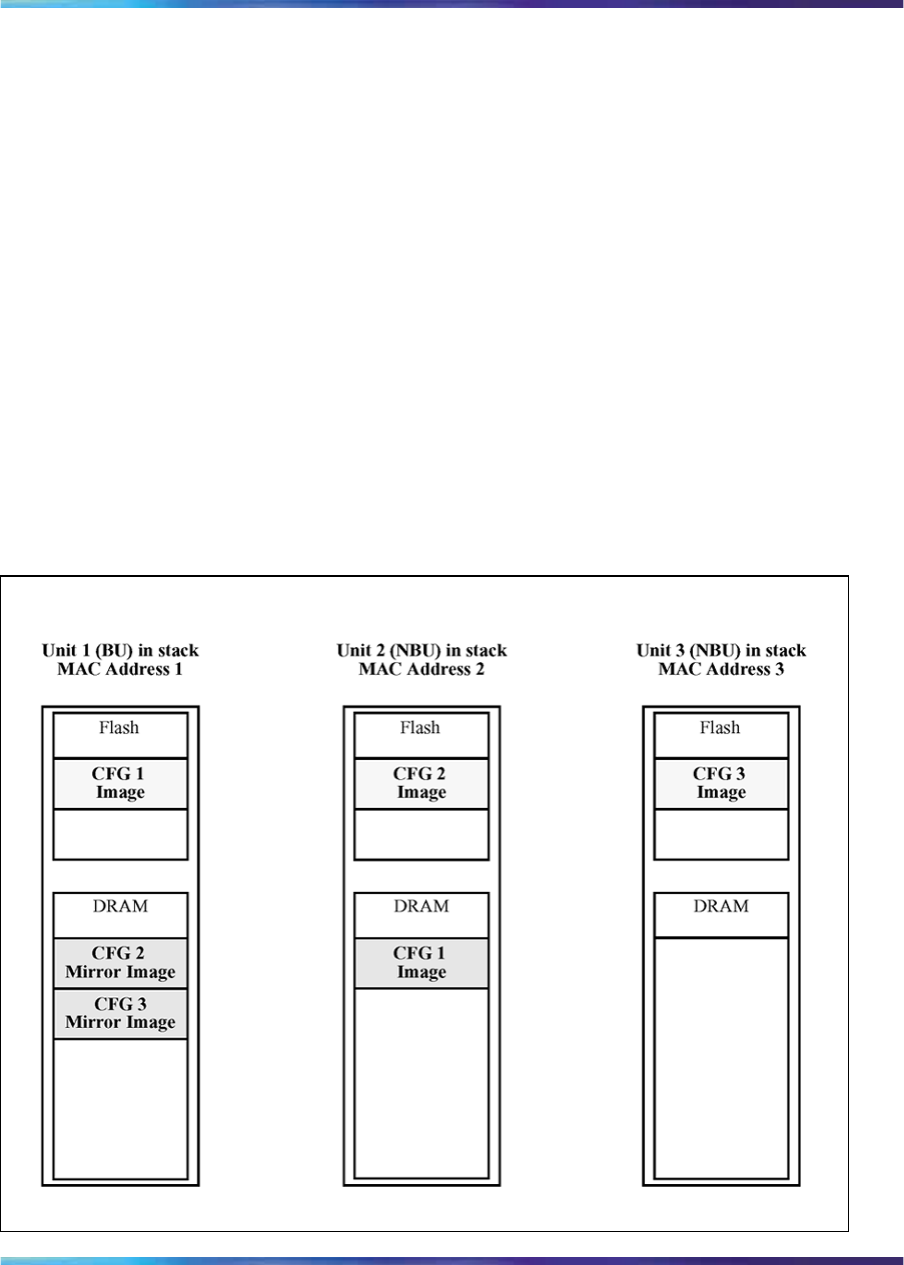
56 Nortel Ethernet Routing Switch 2500 Series stacking
CFG mirror image process
The CFG mirror image process is triggered by specific events.
Power Cycle After a power cycle, all the CFG images in a stack are
mirrored.
Figure 15 "CFG mirror process in stack" (page 56) illustrates the CFG mirror
images in a three-unit stack after the stack is powered on. Unit 1 is the
Based Unit (BU) and all other units are Non-Based Units (NBU).
•Unit 1 (BU) contains mirror images for unit 2 (CFG 2) and unit 3 (CFG 3).
•Unit 2 (NBU), is the TEMP-BU. It contains a mirror image of unit 1 (CFG
1), in case the BU (unit 1) is removed from the stack.
•All three mirror images (CFG 1, CFG 2, and CFG 3) are active.
•Unit 2 is the Associated Unit of the CFG 2 mirror image.
•The Mac Address 2 is the Associated Mac Address (AMA) of the CFG
2 mirror image.
Figure 15
CFG mirror process in stack
Nortel Ethernet Routing Switch 2500 Series
Overview — System Configuration
NN47215-500 (323162-B) 02.02 Standard
4.1 19 November 2007
Copyright © 2007, Nortel Networks
.
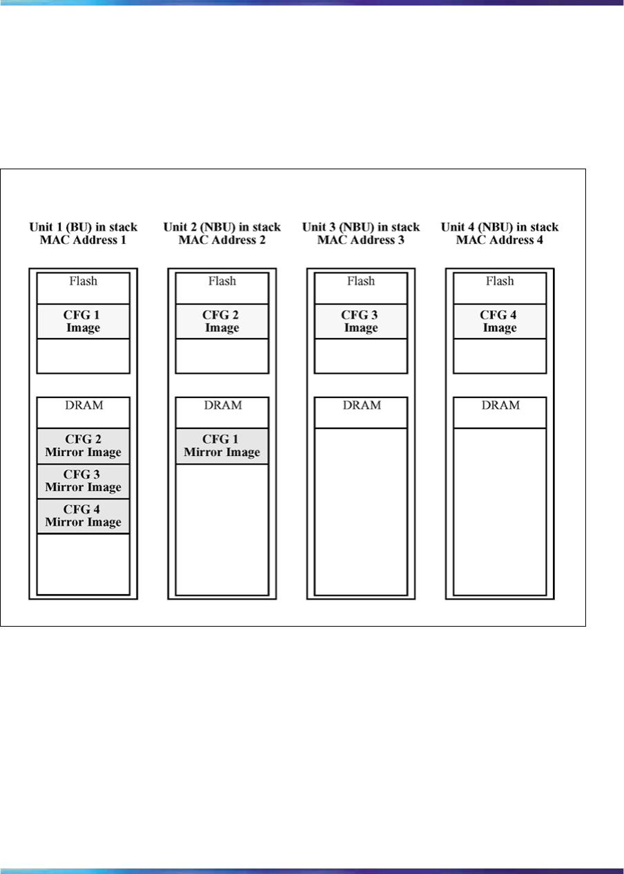
Auto Unit Replacement 57
Adding a unit In a stack that does not have any INACTIVE CFG mirror
images, adding a new unit causes the CFG image of the new unit to be
mirrored in the stack. For example, in Figure 16 "CFG mirror images in the
stack after adding unit 4" (page 57), after adding unit 4 to the stack, the
CFG 4 mirror image is created in the BU (unit 1).
Figure 16
CFG mirror images in the stack after adding unit 4
Removing an NBU When an NBU is removed from a stack, the related
CFG mirror image in the stack becomes INACTIVE.
The AUR feature ensures that the stack always has two copies of an
INACTIVE CFG mirror image. These two copies must not reside in the
same unit in the stack.
For example, after the removal of unit 4 from the stack shown in Figure 16
"CFG mirror images in the stack after adding unit 4" (page 57), the CFG 4
mirror image becomes INACTIVE (see Figure 17 "CFG mirror images after
removing unit 4" (page 58)). Another copy of the INACTIVE CFG 4 mirror
image is also created in unit 2.
Nortel Ethernet Routing Switch 2500 Series
Overview — System Configuration
NN47215-500 (323162-B) 02.02 Standard
4.1 19 November 2007
Copyright © 2007, Nortel Networks
.
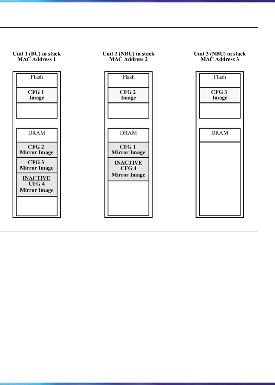
58 Nortel Ethernet Routing Switch 2500 Series stacking
Figure 17
CFG mirror images after removing unit 4
Removing a BU When a BU is removed, the TEMP-BU assumes the
role of the BU. Because all the CFG mirror images of the NBUs reside in
the removed BU, the TEMP-BU mirrors all the CFG image of the NBUs
in the stack.
After the removal of the BU from the stack shown in Figure 16 "CFG mirror
images in the stack after adding unit 4" (page 57), the TEMP-BU (unit 2)
has to mirror all the CFG images in the stack (see Figure 18 "CFG mirror
images in the stack after removing the BU (unit 1)" (page 59)). The feature
also ensures that the stack always has two copies of an INACTIVE CFG
mirror image.
Nortel Ethernet Routing Switch 2500 Series
Overview — System Configuration
NN47215-500 (323162-B) 02.02 Standard
4.1 19 November 2007
Copyright © 2007, Nortel Networks
.
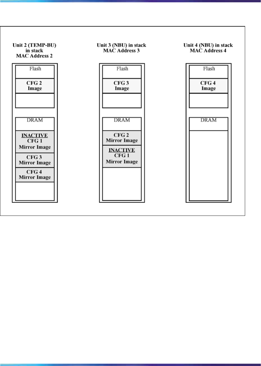
Auto Unit Replacement 59
Figure 18
CFG mirror images in the stack after removing the BU (unit 1)
As shown in Figure 18 "CFG mirror images in the stack after removing
the BU (unit 1)" (page 59):
•Unit 2 becomes the TEMP-BU.
•The CFG 1 mirror image (residing in unit 2) becomes INACTIVE.
•A second copy of the INACTIVE CFG 1 mirror image is created in unit 3.
•The TEMP-BU (unit 2) contains all CFG mirror images of the stack’s
NBUs.
•The CFG 2 mirror image is created in unit 3. Unit 3 becomes the next
TEMP-BU in case the current TEMP-BU is removed.
Restoring a CFG image
Restoring a CFG image is a process that overwrites the CFG image of a
new unit in a stack with an INACTIVE mirror image stored in the stack.
Nortel Ethernet Routing Switch 2500 Series
Overview — System Configuration
NN47215-500 (323162-B) 02.02 Standard
4.1 19 November 2007
Copyright © 2007, Nortel Networks
.

60 Nortel Ethernet Routing Switch 2500 Series stacking
ATTENTION
Restore a CFG image to a new unit happens only if the following conditions are
met.
•The AUR feature is enabled.
•There is at least one INACTIVE CFG mirror image in the stack.
•The MAC Address of the new unit is different from all the AMA of the
INACTIVE CFG mirror images in the stack.
The image restore process consists of the following steps:
Step Action
1Adding a new unit to a stack
2The INACTIVE CFG mirror image in the stack is sent to the new unit.
The INACTIVE CFG mirror image becomes ACTIVE.
3The new unit saves the received CFG image to its flash.
4The new unit resets itself.
—End—
For example, if a unit 5 (MAC Address 5) is added to the stack shown in
Figure 18 "CFG mirror images in the stack after removing the BU (unit 1)"
(page 59), the following occurs (see Figure 19 "CFG mirror images in the
stack after adding unit 5" (page 61)):
•The INACTIVE CFG 1 mirror image is copied to the CFG 5 image. Unit
5 now has the configuration of unit 1 that is no longer in the stack.
•The INACTIVE CFG 1 mirror image in unit 2 becomes ACTIVE.
•The INACTIVE CFG 1 mirror image in unit 3 is removed.
•The MAC Address 5 of the unit 5 becomes the new AMA of the CFG
1 mirror image.
Nortel Ethernet Routing Switch 2500 Series
Overview — System Configuration
NN47215-500 (323162-B) 02.02 Standard
4.1 19 November 2007
Copyright © 2007, Nortel Networks
.
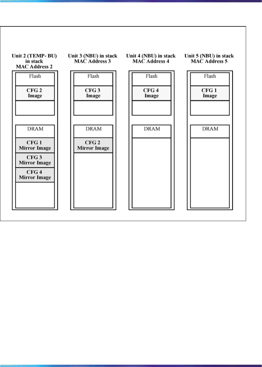
Auto Unit Replacement 61
Figure 19
CFG mirror images in the stack after adding unit 5
Synchronizing the CFG mirror images with CFG images
A CFG mirror image is updated whenever a CFG flash synchronization
occurs in the AU.
Configuring AUR using the CLI
This section describes the CLI commands used in AUR configuration.
show stack auto-unit-replacement command
The show stack auto-unit-replacement command displays the
current AUR settings.
The syntax for this command is:
show stack auto-unit-replacement
The stack auto-unit-replacement enable command is in all
command modes.
Nortel Ethernet Routing Switch 2500 Series
Overview — System Configuration
NN47215-500 (323162-B) 02.02 Standard
4.1 19 November 2007
Copyright © 2007, Nortel Networks
.

62 Nortel Ethernet Routing Switch 2500 Series stacking
There are no parameters or variables for the show stack auto-unit
replacement command.
stack auto-unit-replacement enable command
The stack auto-unit-replacement enable command enables AUR
on the switch.
The syntax for this command is:
stack auto-unit-replacement enable
The stack auto-unit-replacement enable command is executed
in the Global Configuration mode.
There are no parameters or variables for the stack auto-unit-
replacement enable command.
no stack auto-unit-replacement enable command
The no stack auto-unit-replacement enable command disables
AUR on the switch.
The syntax for this command is:
no stack auto-unit-replacement enable
The no stack auto-unit-replacement enable command is
executed in the Global Configuration mode.
There are no parameters or variables for the no stack
auto-unit-replacement enable command.
default stack auto-unit-replacement enable command
The default stack auto-unit-replacement enable command
restores the default AUR settings.
The syntax for this command is:
default stack auto-unit-replacement enable
The default stack auto-unit-replacement enable command is
executed in the Global Configuration mode.
There are no parameters or variables for the default stack
auto-unit-replacement enable command.
Nortel Ethernet Routing Switch 2500 Series
Overview — System Configuration
NN47215-500 (323162-B) 02.02 Standard
4.1 19 November 2007
Copyright © 2007, Nortel Networks
.

Auto Unit Replacement 63
Configuring AUR using Device Manager
You also can enable or disable AUR using Device Manager by toggling the
AutoUnitReplacementEnabled field in the System tab (see "System tab"
(page 259)).
Displaying unit stack uptime
You can display the uptime for each unit in a stack. Unit stack uptime
collects the stack uptime for each unit in a stack and reports this information
when requested. You can determine how long each unit is connected to the
stack. You can use the show stack-info uptime to display the unit
uptimes. The syntax for the show stack-info uptime is
show stack-info uptime
The show stack-info uptime is executed in Privileged EXEC
command mode and takes no parameters.
Nortel Ethernet Routing Switch 2500 Series
Overview — System Configuration
NN47215-500 (323162-B) 02.02 Standard
4.1 19 November 2007
Copyright © 2007, Nortel Networks
.

64 Nortel Ethernet Routing Switch 2500 Series stacking
Nortel Ethernet Routing Switch 2500 Series
Overview — System Configuration
NN47215-500 (323162-B) 02.02 Standard
4.1 19 November 2007
Copyright © 2007, Nortel Networks
.

65
System configuration software features
This chapter describes the software features used for system configuration
on the Ethernet Routing Switch 2500 Series. It includes information about
the following topics:
•x-ref to switch management features
•x-ref to ethernet port management features
•x-ref to other features
Switch management features
Configuration and switch management
The Ethernet Routing Switch 2500 Series that is shipped directly from the
factory is ready to operate in any 10BASE-T or 100BASE-TX standard
network.
You must assign an IP address to the switch. You can set both addresses
by using the Console port or BootP, which resides on the switch. You can
manage the switch using:
•Command Line Interface (CLI)
The CLI is used to automate general management and configuration
of the Ethernet Routing Switch 2500. Use the CLI through a Telnet
connection or through the serial port on the console. See "CLI Basics"
(page 81) for more information.
•Java-based Device Manager
Device Manager is a Java-based set of graphical network management
applications used to configure and manage an Ethernet Routing Switch
2500 Series. See "Getting Started with Device Manager" (page 101) for
more information.
•Web-based management
You can manage the network from the World Wide Web. Access the
web-based Graphical User Interface (GUI) through the Embedded Web
Server (EWS), the HTML-based browser located on your network. The
Nortel Ethernet Routing Switch 2500 Series
Overview — System Configuration
NN47215-500 (323162-B) 02.02 Standard
4.1 19 November 2007
Copyright © 2007, Nortel Networks
.
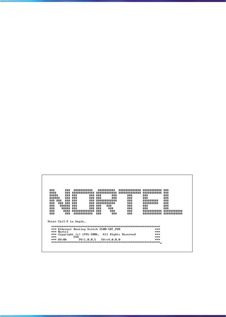
66 System configuration software features
GUI lets you configure, monitor, and maintain your network through Web
browsers. You can also download software using the Web.
For information about web-based management, see "Using the
Web-based management interface" (page 145).
•Any generic SNMP-based network management software.
You can use any generic SNMP-based network management software
to configure and manage an Ethernet Routing Switch 2500 Series.
Console port settings
The efault settings for the Console port are:
•9600 baud with eight data bits
•One stop bit
•No parity as the communications format
•Flow control set to disabled
Switch banner
When you connect to the switch through the Console port or through a
Telnet connection, you are presented with a Nortel switch banner. Enter
Ctrl+Y to proceed to the CLI interface.
Figure 20
Login banner
User name and password
You can use the CLI to set user names as well as passwords for system
access through the CLI, Telnet, and web-based management. The syntax
for the username command is:
username <username> <password> [ro|rw]
Nortel Ethernet Routing Switch 2500 Series
Overview — System Configuration
NN47215-500 (323162-B) 02.02 Standard
4.1 19 November 2007
Copyright © 2007, Nortel Networks
.
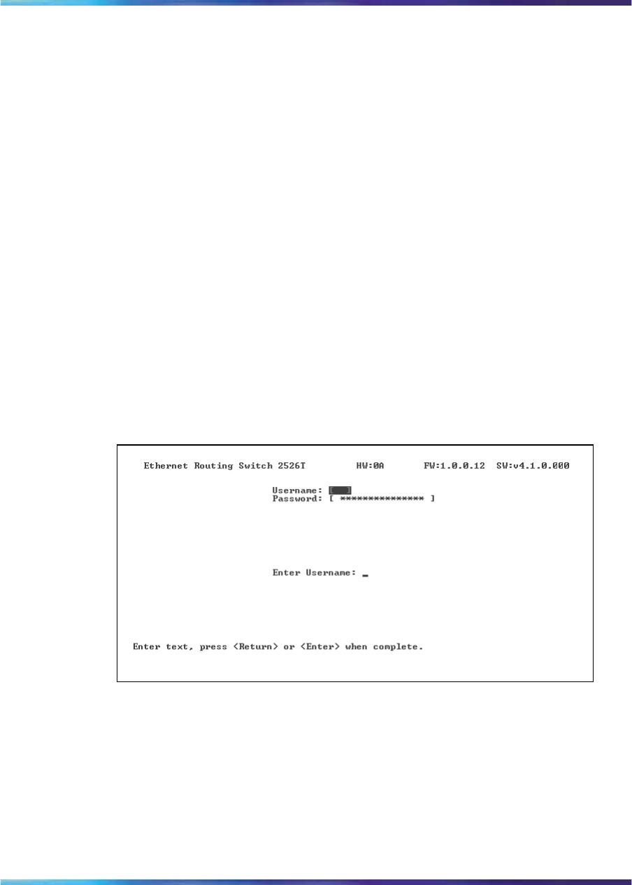
Switch management features 67
You can also set the CLI password using the cli password command,
or the Password Setting web-based management page. When you log on
to the switch, you are prompted to enter a valid user name. Therefore,
ensure you are aware of the valid usernames (default RW and RO) before
you change passwords.
For the standard software image, the default password for user RO is "user"
and for user RW is "secure". For the secure software image, the default
password for RO is "userpasswd" and for RW is "securepasswd".
For more information about this and other advanced security features
supported on the Ethernet Routing Switch 2500 Series, see Nortel Ethernet
Routing Switch 2500 Series Security — Configuration and Management
(NN47215-505).
Logging in
If you set a password using the username or cli password command,
the next time you access the switch, you are prompted for a username
and password as shown in Figure 21 "Login screen" (page 67) (default
usernames are RW and RO).
Figure 21
Login screen
Enter a valid user name and password and press Enter. You are then
directed to the CLI.
For the standard software image, the default password for user RO is "user"
and for user RW is "secure". For the secure software image, the default
password for RO is "userpasswd" and for RW is "securepasswd".
Nortel Ethernet Routing Switch 2500 Series
Overview — System Configuration
NN47215-500 (323162-B) 02.02 Standard
4.1 19 November 2007
Copyright © 2007, Nortel Networks
.

68 System configuration software features
For information about the security features on the switch, see Nortel
Ethernet Routing Switch 2500 Series Security — Configuration and
Management (NN47215-505).
Autosave feature
By default, every 60 seconds the Ethernet Routing Switch checks whether
a configuration change has occurred, or if a log message is written to
nonvolatile storage. If one of these two events has occurred, the system
automatically saves its configuration and the nonvolatile log to flash memory.
Also, the system automatically saves the configuration file if a system reset
command is invoked by the user.
ATTENTION
Do not power off the switch within 60 seconds of changing any configuration
parameters. Doing so causes loss of changes in the configuration parameters.
You can enable or disable the autosave feature using the autosave enable
and no autosave enable commands.
You can use the CLI command copy config nvram to force a manual save of
the configuration when the autosave feature is disabled.
Using SNTP
The Simple Network Time Protocol (SNTP) feature synchronizes the
Universal Coordinated Time (UTC) to an accuracy within 1 second. This
feature adheres to the IEEE RFC 2030 (MIB is the s5agent). With this
feature, the system can obtain the time from any RFC 2030-compliant
NTP/SNTP server.
ATTENTION
If you have trouble using this feature, try other NTP servers. Some NTP servers
can be overloaded or currently inoperable.
The system attempts to connect to the NTP server at least three times, with
five minutes duration between each retry. If the connection fails after three
attempts, the system waits for the next synchronization time (the default is
24 hours) and begins the process again.
The SNTP provides a real-time timestamp for the software, shown as
Greenwich Mean Time (GMT).
If the SNTP is enabled (the default value is disabled), the system
synchronizes with the configured NTP server at bootup and at
user-configurable periods thereafter (the default sync interval is 24 hours).
The first synchronization is not performed until network connectivity is
established.
Nortel Ethernet Routing Switch 2500 Series
Overview — System Configuration
NN47215-500 (323162-B) 02.02 Standard
4.1 19 November 2007
Copyright © 2007, Nortel Networks
.

Switch management features 69
The SNTP supports primary and secondary NTP servers. The system tries
the secondary NTP server only if the primary NTP server is unresponsive.
Configuring with CLI
To use the CLI to configure the SNTP feature, use the following procedure:
Step Action
1Set the primary and secondary NTP server.
2Enable the SNTP.
3Display the UTC time.
4Optionally, to ensure the synchronization happens immediately,
force a synchronization.
—End—
Setting local time zone
The SNTP uses Universal Coordinated Time (UTC) for all time
synchronizations so it is not affected by different time zones. For the switch
to report the correct time for your local time zone and daylight savings time,
you must use the following commands:
•"clock time-zone" (page 213)
•"no clock time-zone" (page 213)
•"clock summer-time" (page 213)
•"no clock summer-time" (page 214)
•"show clock time-zone" (page 214)
•Figure 75 "show clock summer-time" (page 215)
Using DNS to ping and Telnet
You can use the DNS client to ping or Telnet to a host server or to a host
by name.
To use this feature, you must configure at least one Domain Name Server
(DNS). You can also configure a default domain name. If you configure
a default domain name, that name is appended to host names that do
not contain a dot. The default domain name and addresses are saved in
NVRAM.
Nortel Ethernet Routing Switch 2500 Series
Overview — System Configuration
NN47215-500 (323162-B) 02.02 Standard
4.1 19 November 2007
Copyright © 2007, Nortel Networks
.

70 System configuration software features
The host names for ping and Telnet cannot be longer than 63 alphanumeric
characters, and the default DNS domain name cannot be longer than 255
characters.
Configuring with CLI
You can use the CLI to configure the DNS client. Following are the
commands used to configure the DNS client using the CLI.
•show ip dns command
•ping command
•ip name-server command
•no ip name-server command
•ip domain-name command
•no ip domain-name command
•default ip domain-name command
You can also use the ping command to specify additional ping parameters,
including the number of ICMP packets to be sent, the packet size, the
interval between packets, and the timeout. You can also set the ping to
continuous, or you can set a debug flag to obtain extra debug information.
For more information about these commands, see "System configuration
using the CLI" (page 177).
BootP automatic IP configuration/MAC address
The Ethernet Routing Switch 2500 Series has a unique 48-bit hardware
address, or MAC address, that is printed on a label on the back panel. You
can use this MAC address when you configure the network BootP server
to recognize the Ethernet Routing Switch 2500 Series BootP requests. A
properly configured BootP server lets the switch automatically learn its
assigned IP address, subnet mask, IP address of the default router (default
gateway), and software image file name.
For more information and an example of a BootP configuration file, see
Appendix "Sample BootP configuration file" (page 351).
Choosing a BootP request mode
The BootP Request Mode field in the IP Configuration window lets you
choose which method the switch uses to broadcast BootP requests:
•BootP or Default IP
•BootP Always
•BootP Disabled
Nortel Ethernet Routing Switch 2500 Series
Overview — System Configuration
NN47215-500 (323162-B) 02.02 Standard
4.1 19 November 2007
Copyright © 2007, Nortel Networks
.

Switch management features 71
•BootP or Last Address
ATTENTION
Whenever the switch is broadcasting BootP requests, the BootP process
eventually times out if a reply is not received. When the process times out, the
BootP request mode automatically changes to BootP Disabled mode. To restart
the BootP process, change the BootP request mode to any of the three following
modes:
•BootP or Default IP
•BootP Always
•BootP or Last Address
BootP or Default IP
The Ethernet Routing Switch 2500 Series operates in the BootP or Default
IP mode (the default mode) as follows:
•After the switch is reset or power cycled, if the switch has a configured
IP address other than 0.0.0.0 or the default IP address, then the switch
uses the configured IP address.
•If the configured IP address is 0.0.0.0 or the default IP address
(192.168.1.1/24), then the switch attempts BootP for 1 minute.
•If BootP succeeds, then the switch uses the IP information provided.
•If BootP fails and the configured IP address is the default, then the
switch uses the default IP address (192.168.1.1/24).
•If BootP fails and the configured IP address is 0.0.0.0, then the switch
retains this address.
BootP Always
This option lets you manage the switch that is configured with the IP address
obtained from the BootP server. The Ethernet Routing Switch 2500 Series
operates in the BootP Always mode as follows:
•The switch continues to broadcast BootP requests, regardless of
whether an in-band IP address is set from the console terminal.
•If the switch receives a BootP reply that contains an in-band IP address,
the switch uses this new in-band IP address.
•If the BootP server is not reachable, you cannot change the in-band
IP address until the BootP mode is set to BootP Disabled. However,
after a period of a few minutes (appoximately 10 minutes), the switch
automatically enters the BootP Disabled mode. You can then configure
the IP address using the CLI.
Nortel Ethernet Routing Switch 2500 Series
Overview — System Configuration
NN47215-500 (323162-B) 02.02 Standard
4.1 19 November 2007
Copyright © 2007, Nortel Networks
.

72 System configuration software features
If an IP address is not currently in use, these actions take effect immediately.
If an IP address is currently in use, these actions take effect only after the
switch is reset or power cycled.
BootP Disabled
This option lets you manage the switch by using the IP address set from the
console terminal. The Ethernet Routing Switch 2500 Series operates in the
BootP Disabled mode as described in the following steps:
•The switch does not broadcast BootP requests, regardless of whether
an IP address is set from the console terminal.
•The switch can be managed only by using the in-band switch IP address
set from the console terminal.
BootP or Last Address
This option lets you manage the switch even if a BootP server is not
reachable. The Ethernet Routing Switch 2500 Series operates in the BootP
or Last Address mode as described in the following steps:
•When you specify the IP data from the console terminal, the IP address
becomes the in-band address of the switch. BootP requests are not
broadcast. You can manage the switch using this in-band IP address.
•When you do not specify the in-band IP address from the console
terminal, the switch broadcasts BootP requests until it receives a BootP
reply containing an in-band IP address. If the switch does not receive a
BootP reply that contains an in-band IP address within 10 minutes, the
switch uses the last in-band IP address it received from a BootP server.
This IP information is displayed in the Last BootP column.
If the IP address specified as the in-band IP address is not currently in use,
these actions take effect immediately. If an IP address is currently in use,
these actions take effect only after the switch is reset or power cycled.
Default BootP setting
With Release 4.1 software, the default operational mode for BootP on the
switch is BootP or Default IP. The switch requests an IP address from
BootP only if one is not already set from the console terminal (or if the IP
address is the default IP address: 192.168.1.1).
Flash memory storage
Switch software image storage
The Ethernet Routing Switch 2500 Series uses flash memory to store the
switch software image. The flash memory lets you update the software
image with a newer version without changing the switch hardware (see
"Upgrading software" (page 229)). An in-band connection between the
switch and the TFTP load host is required to download the software image.
Nortel Ethernet Routing Switch 2500 Series
Overview — System Configuration
NN47215-500 (323162-B) 02.02 Standard
4.1 19 November 2007
Copyright © 2007, Nortel Networks
.

Switch management features 73
Configuration File Download/Upload
The Configuration Management feature lets you store and retrieve the
configuration parameters of an Ethernet Routing Switch 2500 Series to a
TFTP server. This feature supports two different methods for managing
system configuration files:
•Binary configuration file management
•ASCII configuration file management
Requirements
The following requirements apply to the Configuration file feature:
•The Configuration File feature can only be used to copy standalone
switch configuration parameters to other standalone switches.
•A configuration file obtained from a standalone switch can only be used
to configure other standalone switches that have the same firmware
revision and model type as the donor standalone switch.
Table 8 "Parameters not saved to the configuration file" (page 73) describes
configuration file parameter information.
Table 8
Parameters not saved to the configuration file
These parameters are not saved
In-Band Switch IP Address
In-Band Subnet Mask
Default Gateway
Configuration Image Filename
TFTP Server IP Address
Terminal settings (speed, width, length)
Binary configuration file
You can store the configuration parameters of a switch to a TFTP server
and retrieve the stored parameters to automatically configure a replacement
switch. Certain requirements apply when automatically configuring a switch
using this feature (see "Requirements" (page 73)). You can set up the file
on your TFTP server and set the filename read and write permission to
enabled before you can save the configuration parameters.
Although most configuration parameters are saved to the configuration file,
certain parameters are not saved (see Table 8 "Parameters not saved to the
configuration file" (page 73)).
Nortel Ethernet Routing Switch 2500 Series
Overview — System Configuration
NN47215-500 (323162-B) 02.02 Standard
4.1 19 November 2007
Copyright © 2007, Nortel Networks
.

74 System configuration software features
ASCII configuration file
You can also store the configuration parameters of a switch/stack as an
ASCII configuration file and retrieve the stored file to automatically configure
a replacement switch/stack.
Autotopology
You can enable the Optivity* Autotopology* protocol on the Ethernet Routing
Switch 2500 Series using the CLI. For more information about Autotopology,
go to the Nortel support site: www.nortel.com/support (The product family
for Optivity and Autotopology is Data and Internet.)
Link Layer Discovery Protocol (IEEE 802.1ab)
Release 4.1 software supports the Link Layer Discovery Protocol (LLDP)
(IEEE 802.1ab), which lets stations connected to a LAN to advertise their
capabilities to each other, enabling the discovery of physical topology
information for network management. LLDP-compatible stations can
consist of any interconnection device including PCs, IP Phones, switches,
and routers. Each LLDP station stores LLDP information in a standard
Management Information Base (MIB), making it possible for the information
to be accessed by a network management system (NMS) or application.
Each LLDP station:
•advertises connectivity and management information about the local
station to adjacent stations on the same 802 LAN (802.3 Ethernet with
Ethernet Routing Switch 2500)
•receives network management information from adjacent stations on
the same LAN
ATTENTION
LLDP works in stack mode.
LLDP makes it possible to discover certain configuration inconsistencies or
malfunctions that can result in impaired communications at higher layers.
For example, it can be used to discover duplex mismatches between an IP
Phone and the connected switch.
LLDP is compatible with IETF PROTO MIB (IETF RFC 2922).
Figure 22 "How LLDP works" (page 75) shows an example of how LLDP
works in a network.
Nortel Ethernet Routing Switch 2500 Series
Overview — System Configuration
NN47215-500 (323162-B) 02.02 Standard
4.1 19 November 2007
Copyright © 2007, Nortel Networks
.
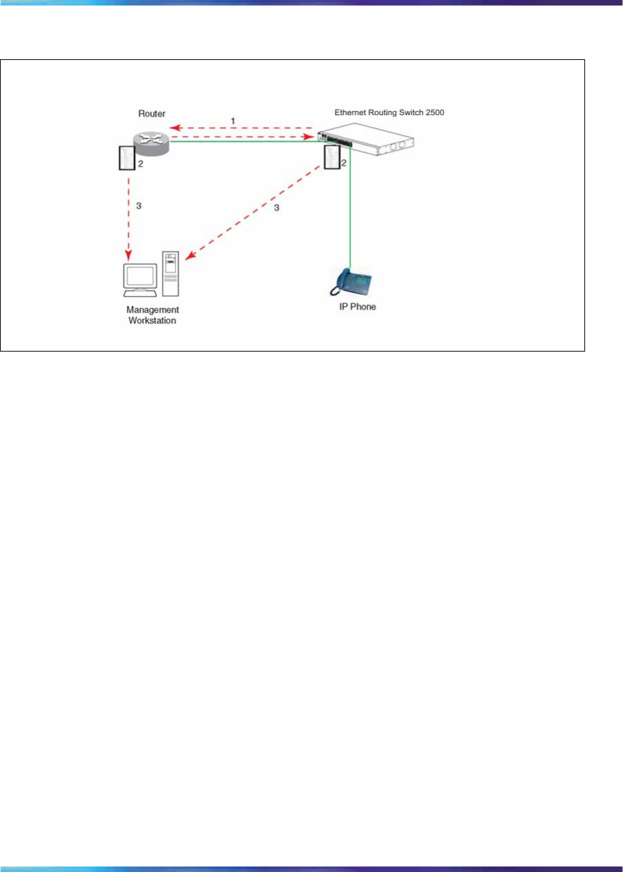
Switch management features 75
Figure 22
How LLDP works
1. The Ethernet Routing Switch and router advertise chassis or port IDs
and system descriptions to each other.
2. The devices store the information about each other in local MIB
databases, accessible using SNMP.
3. A network management system retrieves the data stored by each device
and builds a network topology map.
LLDP operational modes
LLDP is a one-way protocol. An LLDP agent can transmit information
about the capabilities and current status of the system associated with its
MAC service access point (MSAP) identifier. The LLDP agent can also
receive information about the capabilities and current status of the system
associated with a remote MSAP identifier. However, LLDP agents cannot
solicit information from each other.
You can set the local LLDP agent to transmit only, receive only, or to both
transmit and receive LLDP information. You can configure the state for
LLDP reception and transmission using SNMP or CLI commands.
Connectivity and management information
The information fields in each LLDP frame are contained in a Link Layer
Discovery Protocol Data Unit (LLDPDU) as a sequence of short, variable
length, information elements known as type, length, value (TLV). Each
LLDPDU includes the following four mandatory TLVs:
•chassis ID TLV
Nortel Ethernet Routing Switch 2500 Series
Overview — System Configuration
NN47215-500 (323162-B) 02.02 Standard
4.1 19 November 2007
Copyright © 2007, Nortel Networks
.

76 System configuration software features
•port ID TLV
•Time to Live TLV
•End Of LLDPDU TLV
The chassis ID and the port ID values are concatenated to form a logical
MSAP identifier that is used by the recipient to identify the sending LLDP
agent and port.
A non-zero value in the Time to Live (TTL) field of the TTL TLV indicates
to the receiving LLDP agent how long the LLDPDU information from the
MSAP identifier remains valid. All LLDPDU information is automatically
discarded by the receiving LLDP agent if the sender fails to update it
in a timely manner. A zero value in TTL field of Time To Live TLV tells
the receiving LLDP agent to discard the information associated with the
LLDPDU MSAP identifier.
In addition to the four mandatory TLVs, Release 4.1 software supports the
basic management TLV set. You can specify which of these optional TLVs
to include in the transmitted LLDPDUs for each port.
The optional management TLVs are as follows:
•Port Description TLV
•System Name TLV
•System Description TLV
•System Capabilities TLV (indicates both the system supported
capabilities and enabled capabilities, such as end station, bridge, or
router)
•Management Address TLV
Transmitting LLDPDUs When a transmit cycle is initiated, the LLDP
manager extracts the managed objects from the LLDP local system MIB
and formats this information into TLVs. The TLVs are then inserted into
the LLDPDU.
LLDPDUs are regularly transmitted at a user-configurable transmit interval
(tx-delay), or when any of the variables contained in the LLPDU are
modified on the local system (such as system name or management
address). Tx-delay is the minimum delay between successive LLDP frame
transmissions.
TLV system MIBs The LLDP local system MIB stores the information for
constructing the various TLVs to be sent. The LLDP remote system MIB
stores the information received from remote LLDP agents.
Nortel Ethernet Routing Switch 2500 Series
Overview — System Configuration
NN47215-500 (323162-B) 02.02 Standard
4.1 19 November 2007
Copyright © 2007, Nortel Networks
.

Ethernet port management features 77
LLDPDU and TLV error handling LLDPDUs and TLVs that contain
detectable errors are discarded. TLVs that are not recognized, but that also
contain no basic format errors, are assumed to be validated and are stored
for possible later retrieval by network management.
Configuring LLDP using the CLI
For information about configuring LLDP using the CLI, see "Configuring
LLDP using the CLI" (page 77).
Ethernet port management features
Autosensing and autonegotiation
The Ethernet Routing Switch 2500 Series is an autosensing and
autonegotiating device:
•The term autosense refers to the ability of a port to sense the speed of
an attached device.
•The term autonegotiation refers to a standardized protocol (IEEE 802.3u)
that exists between two IEEE 802.3u-capable devices. Autonegotiation
lets the switch select the best of speed and duplex modes.
Autosensing is used when the attached device is not capable of
autonegotiation or is using a form of autonegotiation that is not compatible
with the IEEE 802.3u standard. In this case, because it is not possible to
sense the duplex mode of the attached device, the Ethernet Routing Switch
2500 Series reverts to half-duplex mode.
When autonegotiation-capable devices are attached to the Ethernet Routing
Switch 2500 Series, the ports negotiate down from 100 Mb/s speed and
full-duplex mode until the attached device acknowledges a supported speed
and duplex mode.
Custom Autonegotiation Advertisements
Custom Autonegotiation Advertisements (CANA) lets you customize
the capabilities that you advertise. For example, if a port is capable of
10/100/1000 full duplex operation, the port can be configured to only
advertise 10 half-duplex capabilities.
CANA lets you control the capabilities that are advertised by the Ethernet
switches as part of the autonegotiation process. In the current software
releases, autonegotiation can either be enabled or disabled.
When autonegotiation is disabled, the hardware is configured for a single
(fixed) speed and duplex value. When autonegotiation is enabled, the
advertisement made by the product is a constant value based upon all
speed and duplex modes supported by the hardware.
Nortel Ethernet Routing Switch 2500 Series
Overview — System Configuration
NN47215-500 (323162-B) 02.02 Standard
4.1 19 November 2007
Copyright © 2007, Nortel Networks
.

78 System configuration software features
When autonegotiating, the switch selects the highest common operating
mode supported between the switch and its link partner.
In certain situations, it is useful to autonegotiate a specific speed and
duplex value. In these situations, the switch can allow for attachment at an
operating mode other than its highest supported value.
For example, if the switch advertises only a 100 Mbps full-duplex capability
on a specific link, the link goes active only if the neighboring device is also
capable of autonegotiating a 100 Mbps full-duplex capability. This prevents
mismatched speed and duplex modes if customers disable autonegotiation
on the neighboring device.
ATTENTION
The CANA feature is available only for built-in 10/100 Ethernet ports and combo
ports (not available for rear ports).
You can only enable CANA through the CLI. When CANA is enabled on a port,
autonegotiation status is displayed as Custom in the web-based management
interface.
High speed flow control
The high speed flow control feature lets you control traffic and avoid
congestion on the gigabit full-duplex link. If the receive port buffer becomes
full, the Ethernet Routing Switch 2500 Series issues a flow-control signal
to the device at the other end of the link to suspend transmission. When
the receive buffer is no longer full, the switch issues a signal to resume the
transmission. You can choose Symmetric or Asymmetric flow control mode.
High speed flow control cannot be configured unless you set Autonegotiation
to Disabled on the port and the speed/duplex is at 1000/full.
Two high speed flow control modes are available:
Symmetric mode
This mode lets both GBIC port and its link partner to send flow control
pause frames to each other.
When a pause frame is received (by either the GBIC port or its link partner),
the port suspends transmission of frames for a number of slot times specified
in the control frame or until a pause-release control frame is received. Both
devices on the link must support this mode when it is selected.
Nortel Ethernet Routing Switch 2500 Series
Overview — System Configuration
NN47215-500 (323162-B) 02.02 Standard
4.1 19 November 2007
Copyright © 2007, Nortel Networks
.

Other features 79
Asymmetric mode
This mode lets the link partner send flow control pause frames to the
GBIC port. When a pause frame is received, the receiving port suspends
transmission of frames for a number of slot times specified in the control
frame or until a pause-release control frame is received.
In this mode, the GBIC port is disabled from transmitting pause frames to its
link partner. Use this mode when the GBIC port is connected to a buffered
repeater device.
You can choose a high speed flow control mode using CLI commands. For
more information about the commands see "Enabling flow control" (page
240).
Rate Limiting Configuration
The Rate Limiting feature lets you configure the threshold limits for broadcast
and multicast packets ingressing on a port for a given time interval. The
Ethernet Routing Switch 2500 Series drops any packets received above the
threshold value if the traffic ingressing on the port exceeds the threshold.
The hardware restrictions on this platform do not allow you to determine if
the traffic from a port is the cause of excess broadcast or multicast traffic.
Consequently you cannot perform port specific actions such as disabling
a port. You can generate a trap to detect the excess traffic or you can
configure the switch to store a message in the system log when the traffic
on the port exceeds the threshold value. This message in the system log
conveys that some traffic to the switch is dropped.
When the volume of either packet type is high, placing severe strain on
the network (often referred to as a "storm"), you can set the forwarding
rate of those packet types to not exceed a specified percentage of the total
available bandwidth. The pps (Packets Per Second) value you set is a small
amount of the maximum value of pps for the maximum available bandwidth
that is 262143 pps.
ATTENTION
All Rate Limiting configuration settings are applied across the entire unit. You
cannot set some ports in the unit to limit broadcast traffic with a value of X pps
and some other ports in the same to limit multicast traffic with a value of Y pps.
Other features
RFCs For more information about networking concepts, protocols, and topologies,
consult the following RFCs:
•RFC 1213 (MIB-II)
Nortel Ethernet Routing Switch 2500 Series
Overview — System Configuration
NN47215-500 (323162-B) 02.02 Standard
4.1 19 November 2007
Copyright © 2007, Nortel Networks
.

80 System configuration software features
•RFC 1493 (Bridge MIB)
•RFC 1573 (Interface MIB)
•RFC 1643 (Ethernet MIB)
•RFC 1757 (RMON)
•RFC 1271 (RMON)
•RFC 1157 (SNMP)
Standards
The following IEEE Standards also contain information germane to the
Ethernet Routing Switch 2500 Series:
•IEEE 802.1D (Standard for Spanning Tree Protocol)
•IEEE 802.3 (Ethernet)
•IEEE 802.1Q (VLAN Tagging)
Nortel Ethernet Routing Switch 2500 Series
Overview — System Configuration
NN47215-500 (323162-B) 02.02 Standard
4.1 19 November 2007
Copyright © 2007, Nortel Networks
.

81
CLI Basics
You can manage the Ethernet Routing Switch 2500 Series with the following
management tools:
•Device Manager (GUI)
•Web-based management system
•Command Line Interface (CLI)
The Ethernet Routing Switch 2500 Series Command Line Interface (CLI) is
a management tool that provides methods for configuring, managing, and
monitoring the operational functions of the switch. You can access CLI
through a console terminal directly connected to the switch Console port,
remotely through a dial-up modem connection, in-band through a Telnet
session. For a complete, alphabetical list of CLI commands, see Appendix
"Command List" (page 353).
You can use the CLI interactively, or you can load and execute CLI "scripts."
CLI scripts are loaded in one of the following ways:
•Entering the configure network command
•Manually loading the script in the console menu
•Automatically loading the script at boot-up
This chapter contains information about the following CLI topics:
•"CLI command modes" (page 82)
•"Port numbering" (page 85)
•"Accessing CLI" (page 86)
•"Setting the system username and password" (page 87)
•"Getting help" (page 87)
•"Basic navigation" (page 87)
•"Managing basic system information" (page 96)
•"Managing MAC address forwarding database table" (page 98)
Nortel Ethernet Routing Switch 2500 Series
Overview — System Configuration
NN47215-500 (323162-B) 02.02 Standard
4.1 19 November 2007
Copyright © 2007, Nortel Networks
.

82 CLI Basics
CLI command modes
Most CLI commands are available only under a certain command mode.
The Ethernet Routing Switch 2500 Series has the following four command
modes:
•User EXEC
•Privileged EXEC
•Global Configuration
•Interface Configuration
The User EXEC mode is the default mode; it is also referred to as exec.
This command mode is the initial mode of access on powering-up the
Ethernet Routing Switch 2500 Series. In this command mode, the user can
access only a subset of the total CLI commands; however, the commands
in this mode are available while the user is in any of the other four modes.
The commands in this mode are those you would generally need, such
as ping and logout.
Commands in the Privileged EXEC mode are available to all other modes
but the User EXEC mode. The commands in this mode allow you to perform
basic switch-level management tasks, such as downloading the software
image, setting passwords, and booting the Ethernet Routing Switch 2500
Series. The Privileged EXEC mode is also referred to as privExec mode.
The Global Configuration mode and the Interface Configuration mode allow
you to change the configuration of the Ethernet Routing Switch 2500 Series.
Changes made in these command modes are immediately applied to the
switch configuration and saved to NVRAM.
The Global Configuration commands allow you to set and display general
configurations for the switch, such as the IP address, SNMP parameters,
the Telnet access, and VLANs. The Global Configuration mode is also
referred to as config mode.
The Interface Configuration commands allow you to configure parameters
for each port, such as speed and duplex mode. The Interface Configuration
mode is also referred to as config-if mode.
Figure 23 "CLI command mode hierarchy" (page 83) provides an illustration
of the hierarchy of Ethernet Routing Switch 2500 Series CLI command
modes.
Nortel Ethernet Routing Switch 2500 Series
Overview — System Configuration
NN47215-500 (323162-B) 02.02 Standard
4.1 19 November 2007
Copyright © 2007, Nortel Networks
.
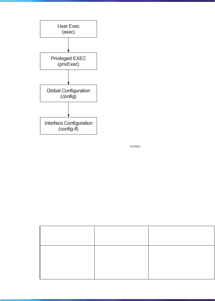
CLI command modes 83
Figure 23
CLI command mode hierarchy
You can see a specific value for each command mode at the prompt line,
and you can use specific commands to enter or exit each command mode
(Table 9 "Command mode prompts and entrance/exit commands" (page
83)). Additionally, you can only enter command modes from specific modes
and only exit to specific command modes.
Table 9 "Command mode prompts and entrance/exit commands" (page
83) describes the command mode prompts and entrance/exit commands.
Table 9
Command mode prompts and entrance/exit commands
Command
mode
Sample Prompt for
the Ethernet
Switch 2500 Enter/exit command
User EXEC
(exec)
2500T> Default mode, automatically
enter
logout or exit to quit to
Main Menu
Nortel Ethernet Routing Switch 2500 Series
Overview — System Configuration
NN47215-500 (323162-B) 02.02 Standard
4.1 19 November 2007
Copyright © 2007, Nortel Networks
.

84 CLI Basics
Command
mode
Sample Prompt for
the Ethernet
Switch 2500 Enter/exit command
Privileged EXEC
(privExec)
2500T# enable to enter from User
EXEC mode
logout or exit to quit to
Main Menu
Global
Configuration
(config)
2500T(config)# configure to enter from
Privileged EXEC mode
end or exit to exit to
Privileged EXEC mode;
logout to quit to Main Menu
Interface
Configuration
(config-if)
2500T(config-if)# interface FastEthern
et {<portnum>|all}
to enter from Global
Configuration mode
logout to quit to Main Menu;
end to exit to Privileged
EXEC mode; exit to exit to
Global Configuration mode
The prompt displays the switch name, and the current CLI command mode.
For example:
•User EXEC--2500T>
•Privileged EXEC--2500T#
•Global Configuration--2500T(config)#
•Interface Configuration--2500T(config-if)#
See Appendix "Command List" (page 353) for a complete, alphabetical list
of all CLI commands and where they are explained.
The initial command mode in CLI depends on your access level when you
logged into the Ethernet Routing Switch 2500 Series:
•With no password protection, you can enter the CLI in userExec mode,
and use the enable command to move to the privExec command mode.
•If you have logged into the CLI with read-only access, you enter the CLI
in userExec mode and cannot access any other CLI command modes.
Nortel Ethernet Routing Switch 2500 Series
Overview — System Configuration
NN47215-500 (323162-B) 02.02 Standard
4.1 19 November 2007
Copyright © 2007, Nortel Networks
.

Port numbering 85
•If you have logged into the CLI with read-write access, you enter the
CLI in privExec mode and use the commands to move to the other
command modes.
Port numbering
The port numbering for different versions of Ethernet switches are listed as
follows:
•Ethernet Routing Switch 2526 has 24 10/100 Mb/s ports on the front, as
well as two combo ports, which includes two GBIC or two copper ports
at 10/100/1000Mbps. The switch also provides two 1000 Mb/s ports on
the rear panel.
•Ethernet Routing Switch 2550 has 48 10/100 ports on the front, as well
as two combo ports, which includes two GBIC or two copper ports at
10/100/1000Mbps. The switch also provides two 1000 Mb/s ports on
the rear panel.
The CLI uses the variable <portlist> when a command specifies one or
more ports for the command.
Port numbering in Standalone Mode
In a Standalone Mode, the port number variable is an integer between 1 and
52 for Ethernet Routing Switch 2550 and 1 to 28 for Ethernet Routing Switch
2526. You can use the <portlist> variable in the following formats:
•A single port number— a integer between 1 and 52.
— Example: 7means port 7
•A range of port numbers— a pair of port numbers between 1 and 52
separated by a dash.
— Example: 1-3 means ports 1, 2, and 3
— Example: 5-24 means all ports from port 5 through port 24
•A list of port numbers and/or port ranges, separated by commas.
— Example: 1,3,7 means ports 1, 3, and 7
— Example: 1-3,9-11 means ports 1, 2, 3, 9, 10, and 11
— Example: 1,3-5,9-11,15 means ports 1, 3, 4, 5, 9, 10, 11, and 15
•none means no ports.
•all means all the ports on the standalone Ethernet Routing Switch
2500 Series, including any GBIC ports.
Nortel Ethernet Routing Switch 2500 Series
Overview — System Configuration
NN47215-500 (323162-B) 02.02 Standard
4.1 19 November 2007
Copyright © 2007, Nortel Networks
.
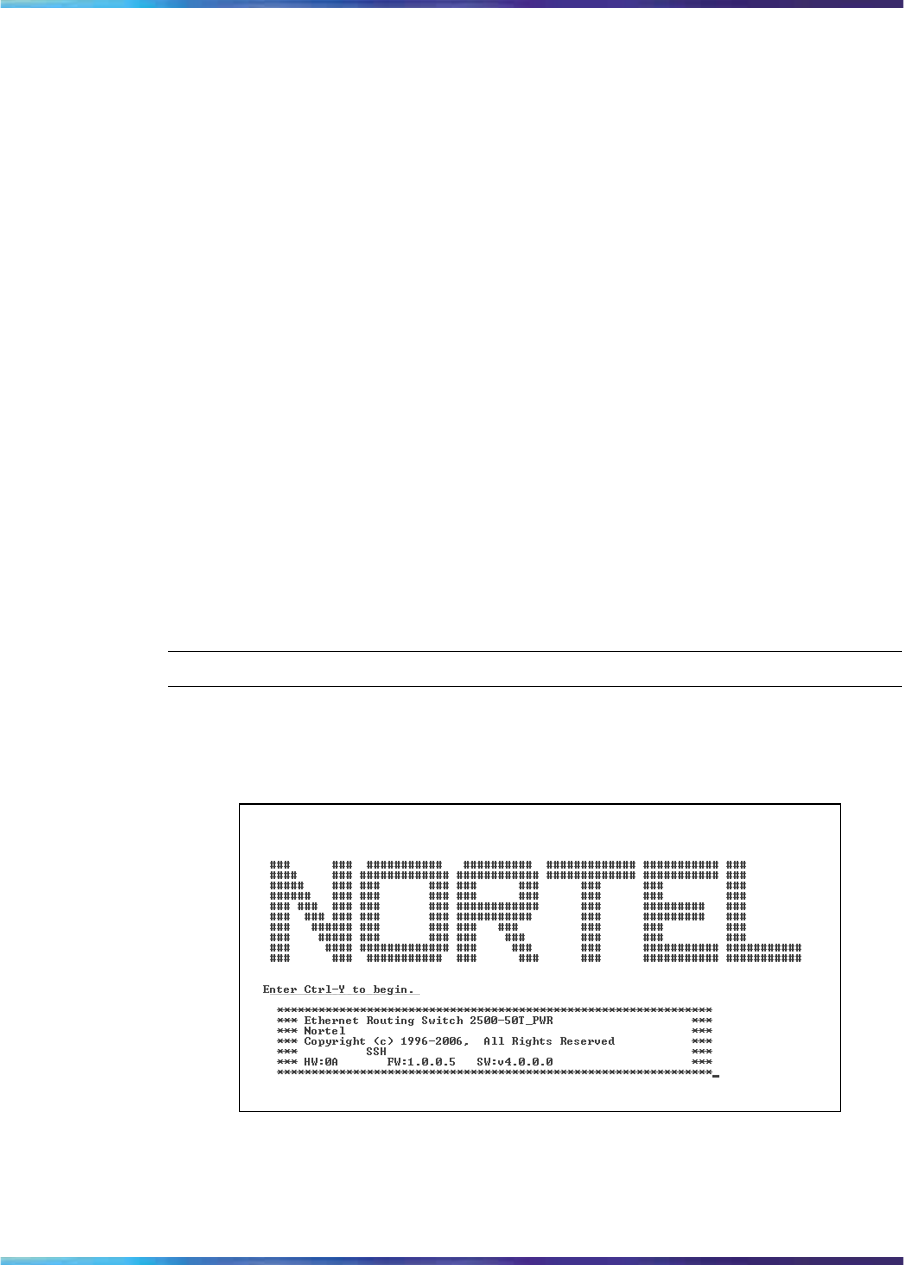
86 CLI Basics
You can also use the unit/port convention with a standalone Ethernet
Routing Switch 2500 Series as long as the unit number is 1.
Accessing CLI
You access the CLI using Telnet or through a direct connection to the switch
from a terminal or personal computer (PC). You can use any terminal or PC
with a terminal emulator as the CLI command station. Make sure that the
terminal has the following features:
•9600 bits per second (b/s), 8 data bits, 1 stop bit, no parity, no flow
control
•Serial terminal-emulation program such as Terminal or Hyperterm for
Windows* 95, Windows 98, Windows 2000, Windows XP or Windows
NT*
•Cable and connector to match the male DTE connector (DB-9) on the
Ethernet Routing Switch 2500 Series Console port, with the DCE/DTE
switch on the switch management module set to DTE
•VT100 Arrows checked in the Terminal Preferences window under
Terminal Options, and Block Cursor unchecked; VT-100/ANSI checked
under Emulation
To access CLI, use the following procedure:
Step Action
1When you access the Ethernet Routing Switch 2500 Series, the
following banner appears.
Ethernet Routing Switch 2500 Series banner
2Press Ctrl+Y, and the CLI prompt appears.
2500>
Nortel Ethernet Routing Switch 2500 Series
Overview — System Configuration
NN47215-500 (323162-B) 02.02 Standard
4.1 19 November 2007
Copyright © 2007, Nortel Networks
.

Basic navigation 87
The > sign at the end of the name of the switch indicates that the
default CLI mode is User EXEC mode. See "CLI command modes"
(page 82), to select the command mode you want to use (and are
authorized to use).
—End—
Setting the system username and password
You can set usernames and passwords for system access through the CLI,
Telnet, and web-based management. For the standard software image, the
default password for user RO is "user" and for user RW is "secure". For
the secure software image, the default password for RO is "userpasswd"
and for RW is "securepasswd". For more information, see Nortel Ethernet
Routing Switch 2500 Series Security — Configuration and Management
(NN47215-505).
Getting helpWhen you navigate through the CLI, online Help is available at all levels.
Entering a portion of the command, space, and a question mark (?) at the
prompt results in a list of all options for that command.
See "help command" (page 89) for more information about specific types
of Help.
Basic navigation
This section discusses basic navigation around the CLI and between
the command modes. As you see, the CLI incorporates various shortcut
commands and keystrokes to simplify its use. This section contains
information about the following topics:
•"General navigation commands" (page 88)
•"Keystroke navigation" (page 88)
•"help command" (page 89)
•"no command" (page 90)
•"default command" (page 90)
•"logout command" (page 90)
•"enable command" (page 91)
•"configure command" (page 91)
•"interface command" (page 91)
•"disable command" (page 92)
Nortel Ethernet Routing Switch 2500 Series
Overview — System Configuration
NN47215-500 (323162-B) 02.02 Standard
4.1 19 November 2007
Copyright © 2007, Nortel Networks
.

88 CLI Basics
•"end command" (page 92)
•"exit command" (page 92)
•"reload command" (page 93)
•"shutdown command" (page 94)
General navigation commands
When you enter "?" at any point in the CLI session, the system retrieves
help information for whatever portion of the command you entered thus far.
See "help command" (page 89) for more information.
The system records the last command in a CLI session. However, the last
command is not saved across reboots.
Add the word no to the beginning of most CLI configuration commands to
clear or remove the parameters of the actual command. For example, when
you enter the command ip address 192.32.154.126, you set the IP
address. However, when you enter no ip address, the system returns
the IP address to zero. See Appendix "Command List" (page 353) for an
alphabetical list of no commands.
Add the word default to the beginning of most CLI configuration
commands to set the parameters of the command to the factory default
values. See Appendix "Command List" (page 353) for an alphabetical list of
default commands.
When you enter a portion of the command and press the [Tab] key, the
system finds the first unambiguous match of a command and displays that
command. For example, if you enter down+[Tab], the system displays
download.
Keystroke navigation
You can change the location of the cursor using the key combinations
shown in the following table.
Table 10
Keystroke navigation
Key combination Function
Ctrl+A Start of line
Ctrl+B Back 1 character
Ctrl+C Abort command
Ctrl+D Delete the character indicated by the cursor
Ctrl+E End of line
Nortel Ethernet Routing Switch 2500 Series
Overview — System Configuration
NN47215-500 (323162-B) 02.02 Standard
4.1 19 November 2007
Copyright © 2007, Nortel Networks
.

Basic navigation 89
Key combination Function
Ctrl+F Forward 1 character
Ctrl+H Delete character left of cursor (Backspace key)
Tab Command/parameter completion
Ctrl+K and Ctrl+R Redisplay line
Ctrl+N or Down arrow Next history command
Ctrl+P or Up arrow Previous history command
Ctrl+T Transpose characters
Ctrl+U Delete entire line
Ctrl+W Delete word left of cursor
Ctrl+X Delete all characters to left of cursor
Ctrl+z Exit Global Configuration mode (to Privileged EXEC
mode)
?Context-sensitive help
Esc+C and Esc+U Capitalize character at cursor
Esc+l Change character at cursor to lowercase
Esc+B Move back 1 word
Esc+D Delete 1 word to the right
Esc+F Move 1 word forward
help command
The help command is in all command modes and displays a brief message
about using the CLI help system. The syntax for the help command is:
help
The help command is executed in the Privileged EXEC command mode.
The help command has no parameters or variables.
Figure 24 "help command output" (page 90) shows the output from the
help command.
Nortel Ethernet Routing Switch 2500 Series
Overview — System Configuration
NN47215-500 (323162-B) 02.02 Standard
4.1 19 November 2007
Copyright © 2007, Nortel Networks
.
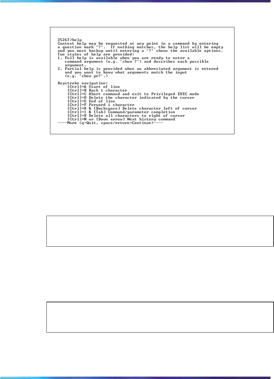
90 CLI Basics
Figure 24
help command output
no command
The no command is always used as a prefix to a configuration command,
and it negates the action performed by that command. The effect of the
no command is to remove or to clear the configuration controlled by the
specified command. Various no commands are in the config and config-if
command modes.
See Appendix "Command List" (page 353) for an alphabetical listing of all
no commands.
ATTENTION
Not all configuration commands support the no prefix command.
default command
The default command is always used as a prefix to a configuration
command, and it restores the configuration parameters to default values.
The default values are specified by each command.
See Appendix A for an alphabetical listing of all default commands.
ATTENTION
Not all commands support the default prefix command.
logout command
The logout command logs you out of the CLI session. The syntax for the
logout command is:
Nortel Ethernet Routing Switch 2500 Series
Overview — System Configuration
NN47215-500 (323162-B) 02.02 Standard
4.1 19 November 2007
Copyright © 2007, Nortel Networks
.

Basic navigation 91
logout
The logout command is in all command modes.
The logout command has no parameters or variables.
enable command
The enable command changes the command mode from User EXEC to
Privileged Exec mode. The syntax for the enable command is:
enable
The enable command is executed in the User Exec command mode.
The enable command has no parameters or variables.
configure command
The configure command moves you to the Global Configuration (config)
command mode and identifies the source for the configuration commands.
The syntax for the configure command is:
configure {terminal|network}
The configure command is executed in the Privileged EXEC command
mode.
Table 11 "configure command parameters and variables" (page
91) describes the parameters and variables for the configure command.
Table 11
configure command parameters and variables
Parameters and
variables Description
terminal | network Specifies the source for the configuration commands for the
Ethernet Routing Switch 2500 Series:
terminal—a you to enter Global Configuration command
mode to enter configuration commands network—lets you
set up parameters for auto-loading a script at boot-up or for
loading and executing a script immediately
interface command
The interface command moves you to the Interface Configuration
(config-if) command mode. The syntax for the interface command is:
interface FastEthernet <portlist>
Nortel Ethernet Routing Switch 2500 Series
Overview — System Configuration
NN47215-500 (323162-B) 02.02 Standard
4.1 19 November 2007
Copyright © 2007, Nortel Networks
.

92 CLI Basics
The interface command is executed in the Global Configuration
command mode.
Table 12 "interface command parameters and variables" (page 92) describes
the parameters and variables for the interface command.
Table 12
interface command parameters and variables
Parameters
and variables Description
<portlist> Specifies the portlist you want to be affected by all the
commands issued in the config-if command mode.
disable command
The disable command returns you to the User EXEC (exec) command
mode. The syntax for the disable command is:
disable
The disable command is executed in the Privileged EXEC command
mode.
The disable command has no parameters or variables.
end command
The end command moves you to the priv Exec mode from either the Global
Configuration (config) mode or the Interface Configuration (config-if) mode.
The syntax for the end command is:
end
The end command has no parameters or variables.
exit command
The exit command moves you around the command modes:
•In User EXEC (exec) and Privileged EXEC (privExec) command modes,
exit lets you quit the CLI session.
•In Global Configuration (config) mode, exit moves you back to the
privExec command mode.
•In Interface Configuration (config-if) command mode, exit moves you
back to the Global Configuration command mode.
The syntax for the exit command is:
Nortel Ethernet Routing Switch 2500 Series
Overview — System Configuration
NN47215-500 (323162-B) 02.02 Standard
4.1 19 November 2007
Copyright © 2007, Nortel Networks
.

Basic navigation 93
exit
The exit command has no parameters or variables.
reload command
The reload command provides you with a configuration rollback
mechanism to prevent loss of connectivity to a switch, typically for remote
configurations. The reload command lets you temporarily disable the
autosave feature for a specified time period (1 to 60 minutes), allowing you
to make a number of configuration changes on remote switches without
affecting the current saved configuration.
During the interval in which the autosave feature is disabled by the reload
command, you must use the copy config nvram, write memory,or
save config command to force a manual save of your configurations.
Once the reload timer expires, the switch reloads the last saved
configuration. To abort the switch reload before the timer expires, you must
enter the reload cancel command.
The reload command provides you with a safeguard against any
misconfigurations when you perform dynamic configuration changes on
a remote switch.
The following example describes how you can use the reload command
to prevent connectivity loss to a remote switch.
Step Action
1Enter the CLI command reload force 30. This instructs the
switch to reboot in 30 minutes, loading the configuration from
NVRAM.
During this 30-minute period, autosave of the configuration to
NVRAM is disabled.
2Execute dynamic switch configuration commands, which take effect
immediately. These configurations are not saved to NVRAM.
3If the configurations cause no problems and switch connectivity is
maintained, you can perform the following:
4Save the current running configuration using the copy config
nvram,write memory, or save config command.
5Since the new configuration is working properly, cancel the reload
using the reload cancel command.
—End—
Nortel Ethernet Routing Switch 2500 Series
Overview — System Configuration
NN47215-500 (323162-B) 02.02 Standard
4.1 19 November 2007
Copyright © 2007, Nortel Networks
.

94 CLI Basics
If you make an error when performing configurations in Step 2 that results in
the loss of switch connectivity (for example, an error in the IP address mask,
MLT configuration, or VLAN trunking), the reload command provides you
with a safeguard: when the reload timer expires, the switch reboots to the
last saved configuration, and connectivity is re-established. Therefore, you
do not have to travel to the remote site to reconfigure the switch.
Initiate the reload command before you start the switch configuration
commands. Once you initiate the command in the CLI, the following
message appears:
Reload (y/n) ?
Enter yes at this prompt to set the switch reload.
The following warning message then appears:
Warning the switch has been set to reload in <xx> minutes.
Current configuration has NOT been saved. Configuration must
be explicitly saved.
Once the reload timer expires, the switch resets, reloads the last saved
configuration, and re-enables the autosave feature.
The syntax for the reload command is:
reload [force] [minutes-to-wait <1-60>] [cancel]
describes the parameters and variables for the interface command.
Table 13
reload command parameters and variables
Parameters
and variables Description
force Instructs the switch to skip the reload confirmation prompt.
minutes-to-wait
<1-60>] Specifies the number of minutes that pass before the switch
reloads itself. The default wait time is set at 10 minutes.
cancel Aborts all scheduled switch reloads
The reload command is executed in the Privileged EXEC command mode.
shutdown command
The shutdown command lets you safely shut down and power off the
switch. Once the shutdown command is initiated, the switch saves the
current configuration and instructs users to power off the switch within the
specified time period (1 to 60 minutes); otherwise, the switch performs a
reset.
Nortel Ethernet Routing Switch 2500 Series
Overview — System Configuration
NN47215-500 (323162-B) 02.02 Standard
4.1 19 November 2007
Copyright © 2007, Nortel Networks
.

Basic navigation 95
When the shutdown command is initiated in the CLI, the following message
appears:
Shutdown (y/n) ?
Enter y at this prompt to shut down the switch.
The following warning message then appears:
Warning the switch/stack has been set to reboot in <xx>
minutes. Current configuration has been saved, no further
configuration changes can be saved until reboot occurs or
’shutdown cancel’ command is issued.
The syntax for shutdown command is:
shutdown [force] [minutes-to-wait <1-60>] [cancel]
Once the shutdown command is initiated, all existing and subsequent
Console Interface sessions display the following message:
Stack will reset in <xxxx> seconds.
While existing CLI sessions do not receive a warning message, all
subsequent CLI sessions display the following message:
The shutdown process is in progress. It is safe to poweroff
the stack. Configuration changes will not be saved.
Shutdown has blocked the flash. Autoreset in <xxxx> seconds.
ATTENTION
You can disable switch ports that are trunk members, if you choose to disable
them one by one. If you choose to disable all ports of the unit or stack, the
changes cannot have effect on the ports belonging to MLTs.
Neither web-based management nor Device Manager receive any shutdown
warning messages.
Table 14 "shutdown command parameters and variables" (page
95) describes the parameters and variables for the shutdown command.
Table 14
shutdown command parameters and variables
Parameters
and variables Description
cancel Aborts all scheduled switch shutdowns
Nortel Ethernet Routing Switch 2500 Series
Overview — System Configuration
NN47215-500 (323162-B) 02.02 Standard
4.1 19 November 2007
Copyright © 2007, Nortel Networks
.

96 CLI Basics
Parameters
and variables Description
force Instructs the switch to skip the shutdown confirmation
prompt.
minutes-to-wait
<1-80> Specifies the number of minutes that pass before the
switch resets itself. The default wait time is set at 10
minutes.
ATTENTION
Any configurations or login performed on the switch after the shutdown command
is initiated are not saved to NVRAM and are lost after the reset.
The shutdown command is executed in the Privileged EXEC command
mode.
Managing basic system information
This section shows you how to view basic system information such as
the current software version. This section contains information about the
following topics:
•"show sys-info command" (page 96)
•"show tech command" (page 97)
show sys-info command
The show sys-info command displays the current system characteristics.
The syntax for the show sys-info command is:
show sys-info
The show sys-info command is executed in the Privileged EXEC
command mode.
The show sys-info command has no parameters or variables.
Figure 25 "show sys-info command output" (page 97) displays sample
output from the show sys-info command.
Nortel Ethernet Routing Switch 2500 Series
Overview — System Configuration
NN47215-500 (323162-B) 02.02 Standard
4.1 19 November 2007
Copyright © 2007, Nortel Networks
.
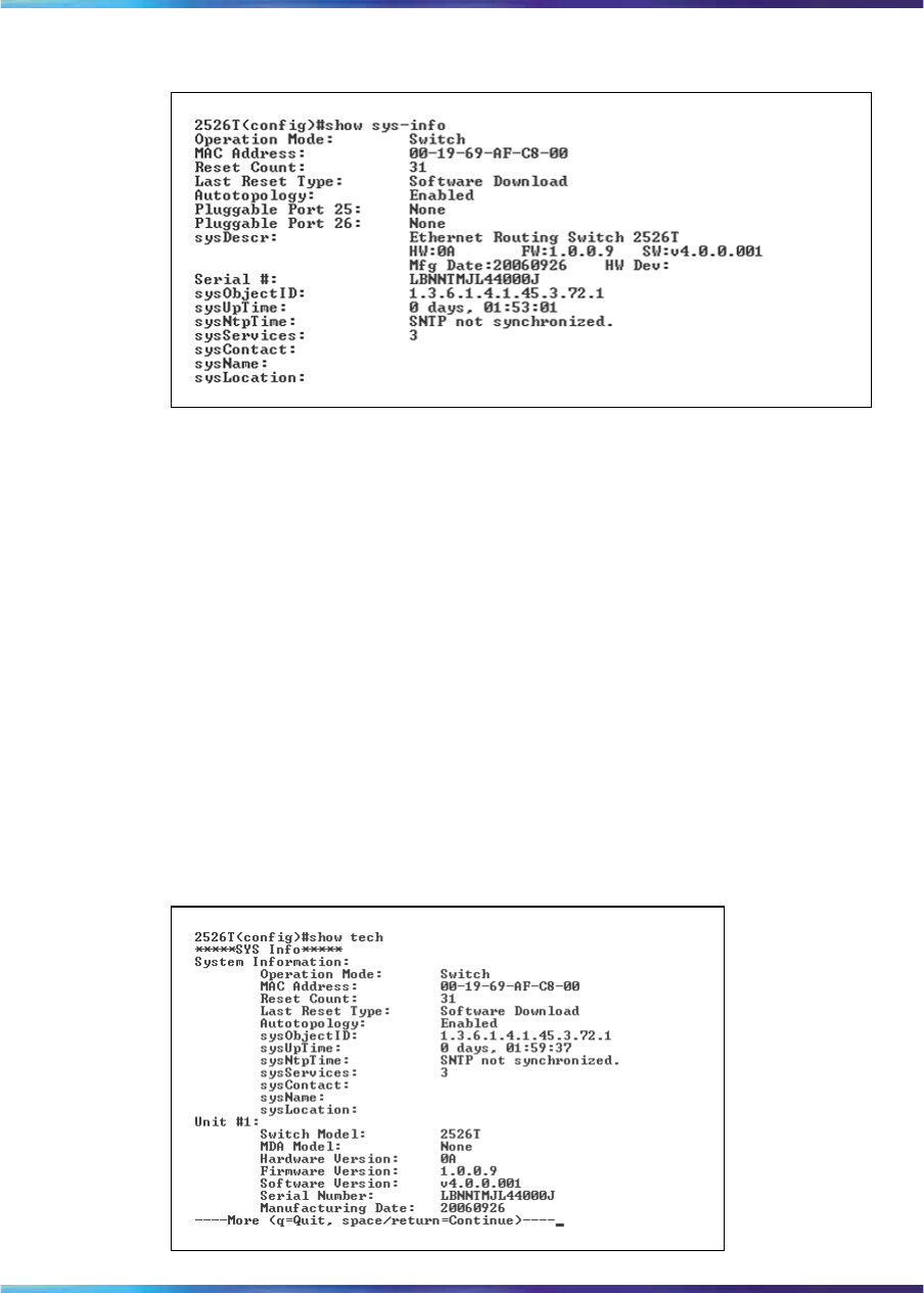
Managing basic system information 97
Figure 25
show sys-info command output
To change the system contact, name, or location, see the snmp-server
command (see Nortel Ethernet Routing Switch 2500 Series Security —
Configuration and Management (NN47215-505)).
show tech command
The show tech command displays detailed system information. The
syntax for the show tech command is:
show tech
The show tech command is executed in the Privileged EXEC command
mode. The show tech command has no parameters or variables.
Figure 26 "show tech command output" (page 97) displays a sample output
from the show tech command.
Figure 26
show tech command output
Nortel Ethernet Routing Switch 2500 Series
Overview — System Configuration
NN47215-500 (323162-B) 02.02 Standard
4.1 19 November 2007
Copyright © 2007, Nortel Networks
.

98 CLI Basics
Managing MAC address forwarding database table
This section describes the commands to view the contents of the MAC
address forwarding database table, as well as setting the age-out time for
the addresses. The following topics are covered:
•"show mac-address-table command" (page 98)
•"mac-address-table aging-time command" (page 99)
•"default mac-address-table aging-time command" (page 99)
show mac-address-table command
The show mac-address-table command displays the current contents
of the MAC address forwarding database table. The syntax for the show
mac-address-table command is:
show mac-address-table [vid <1-4094>] [aging-time] [port
<LINE>][address <H.H.H> {include | exclude <pattern>}]
The show mac-address-table command is executed in the Privileged
EXEC command mode.
Table 15 "show mac-address-table command parameters and variables"
(page 98) describes the parameters and variables for the show
mac-address-table command.
Table 15
show mac-address-table command parameters and variables
Parameters
and variables Description
vid <1-4094> Enter the number of the VLAN you want to display the
forwarding database.
Default is to display the management VLAN’s database.
aging-time Displays the time in seconds after which an unused
entry is removed from the forwarding database.
port <LINE> List of ports.
address <H.H.H> Displays a specific MAC address if it exists in the
database. Enter the MAC address you want displayed.
include | exclude
<pattern>
Lets you filter the results of the command by printing
only those entries in the address table that include or
exclude a given pattern. The value for <pattern>
must be a sequence of 1 to 6 bytes in hex, separated
by dashes.
for example: show mac-address-table port
1/1-5 address include 00-0E-45-23
Nortel Ethernet Routing Switch 2500 Series
Overview — System Configuration
NN47215-500 (323162-B) 02.02 Standard
4.1 19 November 2007
Copyright © 2007, Nortel Networks
.
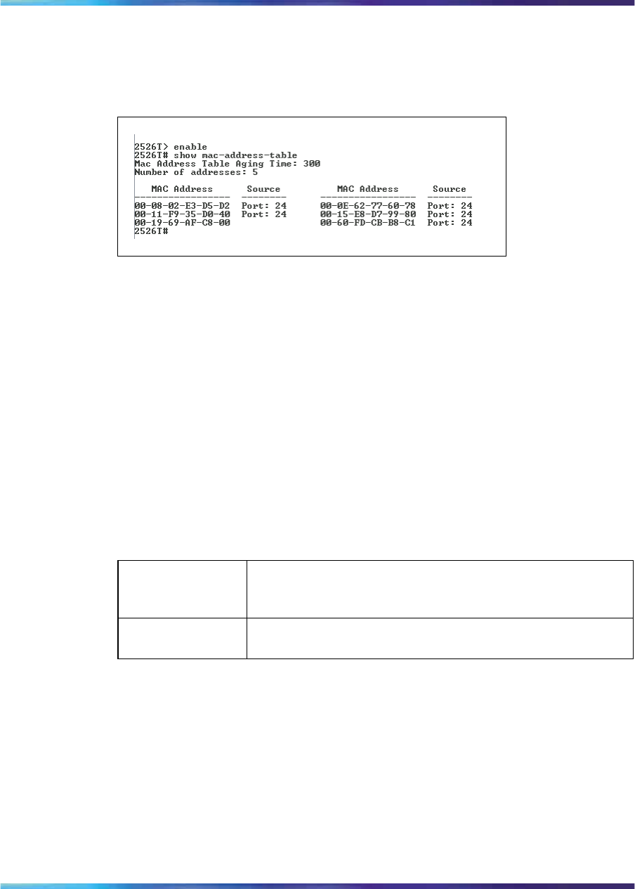
Managing MAC address forwarding database table 99
Figure 27 "show mac-address-table command output" (page 99) displays
sample output from the show mac-address-table command.
Figure 27
show mac-address-table command output
mac-address-table aging-time command
The mac-address-table aging-time command sets the time
that the switch retains unseen MAC addresses. The syntax for the
mac-address-table aging-time command is:
mac-address-table aging-time <time>
The mac-address-table aging-time command is executed in the
Global Configuraion command mode.
Table 16 "mac-address-table aging-time command parameters and
variables" (page 99) describes the parameters and variables for the
mac-address-table aging-time command.
Table 16
mac-address-table aging-time command parameters and variables
Parameters
and
variables Description
time Enter the aging time in seconds that you want for MAC
addresses before they are flushed.
default mac-address-table aging-time command
The default mac-address-table aging-time command sets the
time that the switch retains unseen MAC addresses to 300 seconds. The
syntax for the default mac-address-table aging-time command
is:
default mac-address aging-time
The default mac-address-table aging-time command is executed
in the Global Configuration command mode.
Nortel Ethernet Routing Switch 2500 Series
Overview — System Configuration
NN47215-500 (323162-B) 02.02 Standard
4.1 19 November 2007
Copyright © 2007, Nortel Networks
.

100 CLI Basics
The default mac-address-table aging-time command has no
parameters or variables.
Nortel Ethernet Routing Switch 2500 Series
Overview — System Configuration
NN47215-500 (323162-B) 02.02 Standard
4.1 19 November 2007
Copyright © 2007, Nortel Networks
.

101
Getting Started with Device Manager
The Java Device Manager (JDM) software is a Graphical User Interface
(GUI) that lets you manage the switch. JDM (also referred to as Device
Manager) provides options found in other management tools such as
management of VLANs and MultiLink Trunks, and displaying and printing
of statistics in graph format.
To use Device Manager, you must have network connectivity to a
management station running Device Manager on one of the supported
platforms. You must also assign an IP address to the switch.
This chapter contains information on the following topics:
•"Installing Device Manager" (page 101)
•"Device Manager basics" (page 119)
Installing Device Manager
The JDM software is provided on the device software CD as a self-extracting
executable file, and is also available from the Nortel web site. This chapter
provides instructions for installing the JDM software in a Windows*, UNIX*,
or Linux* environment.
The Java Runtime Environment (JRE) is bundled with the JDM software and
does not require a separate installation.
For details on installing Device Manager, see the following sections:
•"JDM installation precautions" (page 102)
•"Installing the Device Manager software" (page 102)
•"Installing JDM on Windows" (page 102)
•"Installing JDM on UNIX or Linux" (page 110)
•"Starting Device Manager" (page 119)
Nortel Ethernet Routing Switch 2500 Series
Overview — System Configuration
NN47215-500 (323162-B) 02.02 Standard
4.1 19 November 2007
Copyright © 2007, Nortel Networks
.

102 Getting Started with Device Manager
JDM installation precautions
The following warnings apply to Device Manager on all operating
environments:
•The JDM and Ethernet Routing Switch software versions must match for
the correct dialog boxes and information to be shown and accessible.
Please see the Release Notes for a complete compatibility list.
•If you want to use JDM to support multiple Nortel switches in your
network, ensure that the JDM version you use supports each version of
software running on each Nortel device in your network.
•Prior to upgrading JDM, either uninstall your previous version of the
Device Manager software, or install the new software to a different
directory. (You can have multiple versions of Device Manager stored on
your Windows, UNIX, or Linux machine, provided that each version
is stored in a separate directory.)
ATTENTION
Do not install the JDM to a directory where a previous version of Device
Manager software already exists.
•JDM saves the IP addresses that are visited to a settings file. A JDM
uninstall operation does not remove this settings file.
— In a Windows environment, the settings file is dm.xml, and is created
in the jdm folder, under window user profile directory.
— In a UNIX environment, the settings file is ~/.jdm/dm.xml.
— In a Linux environment, the settings file is ~/.jdm/dm.xml.
•The dm.xml file containing IP addresses visited from a previous JDM.
Installing the Device Manager software
Device Manager software can be installed in Windows, UNIX, or Linux
environment. The following sections provide information on the system
requirements and installation procedures to install Device Manager software
in Windows, UNIX, and Linux environments.
•"Installing JDM on Windows" (page 102)
•"Installing JDM on UNIX or Linux" (page 110)
Installing JDM on Windows
This section includes the following topics:
•"Windows minimum requirements" (page 103)
•"Removing previous versions of JDM on Windows" (page 103)
Nortel Ethernet Routing Switch 2500 Series
Overview — System Configuration
NN47215-500 (323162-B) 02.02 Standard
4.1 19 November 2007
Copyright © 2007, Nortel Networks
.

Installing JDM on Windows 103
•"Installing JDM on Windows from the CD" (page 104)
•"Installing JDM on Windows from the web" (page 104)
•"Executing the JDM installation software on Windows" (page 105)
Windows minimum requirements
The minimum system requirements for installing JDM on Microsoft*Windows
NT*, Windows 2000, Windows XP, Windows 2003, or Windows Vista are:
•350 MHz or higher Pentium processor
•512 MB DRAM
•400 MB space on hard drive
Removing previous versions of JDM on Windows
ATTENTION
Removing previous versions of JDM is an optional process. Multiple versions of
JDM can exist on one system, as long as each version is in a separate location.
If you decide to allow previous versions of JDM to remain, then you must choose
a different folder to use during the installation process.
Remove existing versions of Device Manager software by using the Uninstall
DM option that was created in the Windows Start menu during installation.
For example, to remove Device Manager from a Windows XP system using
the default program group, choose the following option from the Windows
Start menu: All Programs>Nortel>Java Device Manager>Uninstall DM.
If no program group was added to the Windows Start menu during
installation, then complete the following steps to remove existing Device
Manager software:
Step Action
1Navigate to the folder where the JDM software is installed.
2Open the UninstallerData sub-folder.
3Run the following file: Uninstall Java Device Manager.exe.
ATTENTION
If more than one version of Device Manager software is installed,
ensure you select the correct software to uninstall.
—End—
Nortel Ethernet Routing Switch 2500 Series
Overview — System Configuration
NN47215-500 (323162-B) 02.02 Standard
4.1 19 November 2007
Copyright © 2007, Nortel Networks
.

104 Getting Started with Device Manager
Installing JDM on Windows from the CD
To access the JDM software from the installation CD:
Step Action
1Close all programs.
2Insert the software CD into your CD-ROM drive.
3From the Windows Start menu, choose Run.
The Run dialog box appears.
4Use Browse to navigate to the drive where the CD-ROM is located.
5On the CD-ROM drive, locate the \Windows\Device Manager
subdirectory.
6Double-click the jdm_xxxx.exe file.
ATTENTION
In the file name, xxxx represents the current version of the JDM software.
Continue with "Executing the JDM installation software on Windows"
(page 105).
—End—
Installing JDM on Windows from the web
To obtain the JDM software from the Nortel web site, use the following
procedure:
Step Action
1Go to the following URL:
www.nortel.com/support
2Select the software support page for your product.
The software page appears.
3Click the Java Device Manager version you want.
The Software Detail Information page appears.
Nortel Ethernet Routing Switch 2500 Series
Overview — System Configuration
NN47215-500 (323162-B) 02.02 Standard
4.1 19 November 2007
Copyright © 2007, Nortel Networks
.
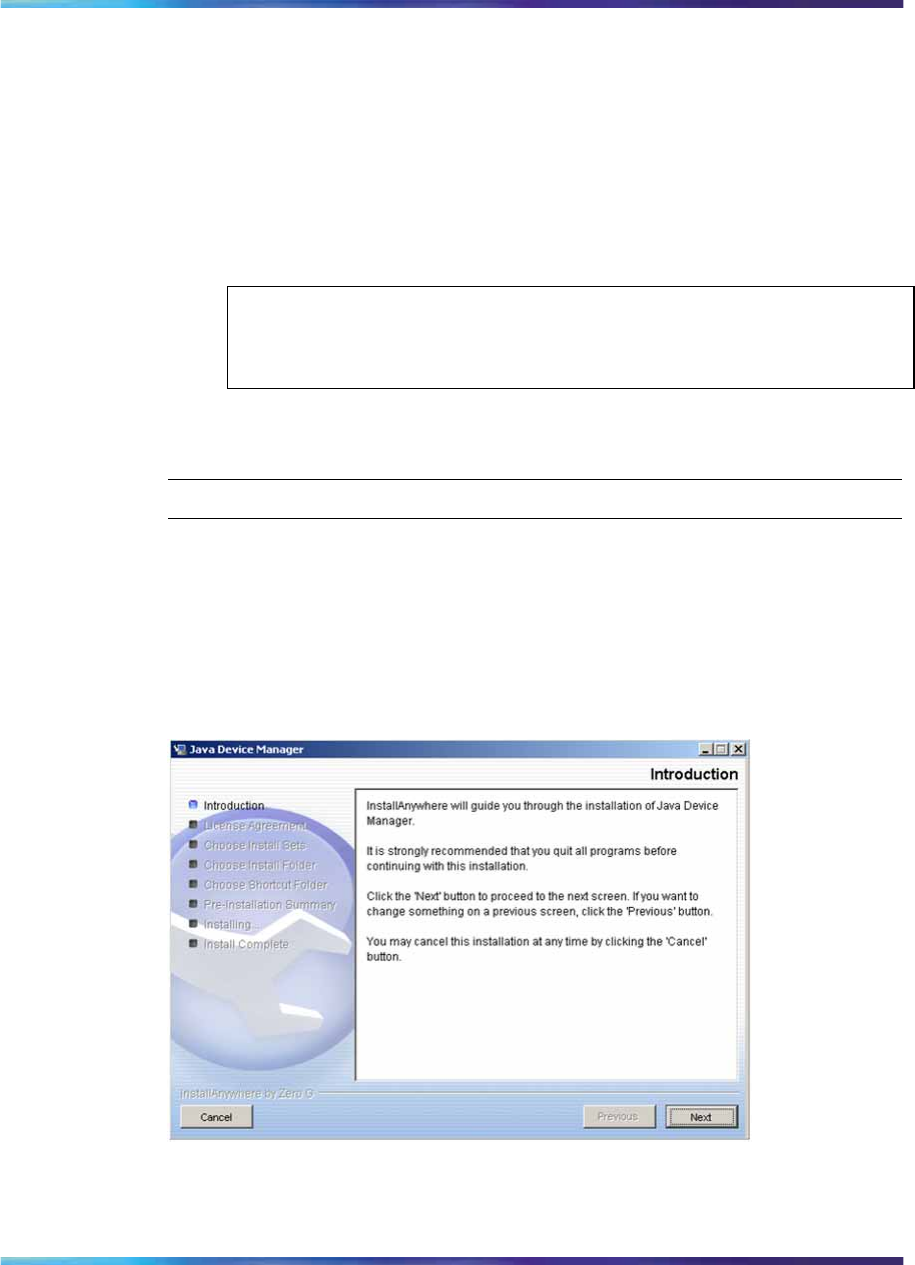
Installing JDM on Windows 105
4Download the JDM software for Windows to a desired directory on
your system. The software download is a self-extracting .exe file.
Once the file transfer is complete, continue with step 5.
5Close all programs.
6Navigate to the directory on your system where you downloaded
the JDM Software.
7Double-click the jdm_xxxx.exe file.
ATTENTION
In the file name, xxxx represents the current version of the JDM software.
Continue with "Executing the JDM installation software on Windows"
(page 105).
—End—
Executing the JDM installation software on Windows
An install screen appears, followed by a Nortel dialog box. When the
InstallAnywhere Introduction dialog box appears you are ready to install
the JDM.
Figure 28
InstallAnywhere Introduction dialog box
Nortel Ethernet Routing Switch 2500 Series
Overview — System Configuration
NN47215-500 (323162-B) 02.02 Standard
4.1 19 November 2007
Copyright © 2007, Nortel Networks
.
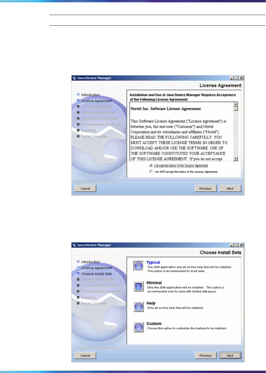
106 Getting Started with Device Manager
Step Action
1Click Next to begin the installation process.
The License Agreement dialog box appears.
2Click I accept the terms of the License Agreement .
License Agreement dialog box
3Click Next.
The Choose Install Set dialog box appears.
Choose Install Set dialog box
Nortel Ethernet Routing Switch 2500 Series
Overview — System Configuration
NN47215-500 (323162-B) 02.02 Standard
4.1 19 November 2007
Copyright © 2007, Nortel Networks
.
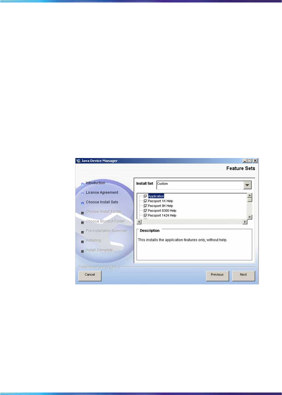
Installing JDM on Windows 107
4Do one of the following:
•Select Typical installation to install the common set features,
as well as online help.
•Select Minimal installation to select minimal features to install
(recommended for those with limited disk space).
•Select Help to install only the online help.
•Select Custom installation to customize the features prior to
installation.
5Click Next.
If you did not select Custom installation in step 4, then the Choose
Install Folder dialog box appears. Continue with step 8.
If you selected Custom installation in step 4, then the Feature Sets
dialog box appears.
Feature Sets dialog box
6Select which features to install from the feature sets list.
7Click Next.
The Choose Install Folder dialog box appears.
Nortel Ethernet Routing Switch 2500 Series
Overview — System Configuration
NN47215-500 (323162-B) 02.02 Standard
4.1 19 November 2007
Copyright © 2007, Nortel Networks
.
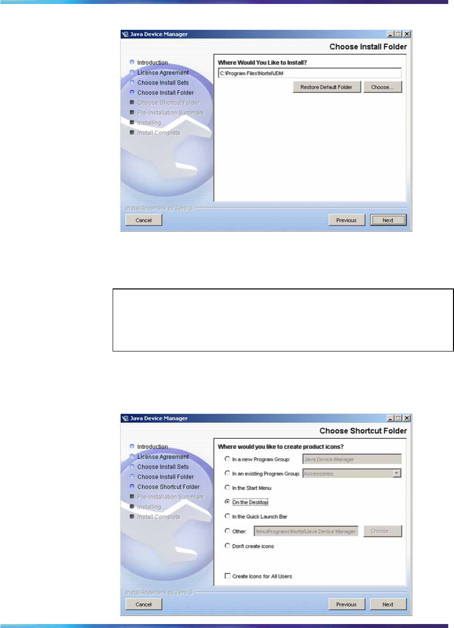
108 Getting Started with Device Manager
Choose Install Folder dialog box
8Click Restore Default Folder to use the default location for JDM, or
click Choose to select a different storage path.
ATTENTION
If Device Manager is already installed on your computer, you must choose
a storage path that does not conflict with the already existing version.
9Click Next.
The Choose Shortcut Folder dialog box appears.
Choose Shortcut Folder dialog box
Nortel Ethernet Routing Switch 2500 Series
Overview — System Configuration
NN47215-500 (323162-B) 02.02 Standard
4.1 19 November 2007
Copyright © 2007, Nortel Networks
.
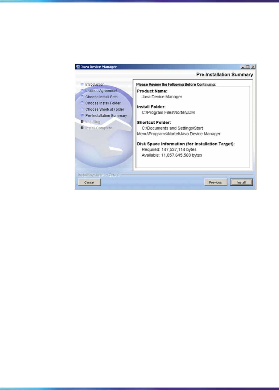
Installing JDM on Windows 109
10 Select the desired shortcut path from the list provided.
11 Click Next.
The Pre-Installation Summary dialog box appears. A summary of
the choices you have made is displayed for confirmation.
Pre-Installation Summary dialog box
12 Verify the folder, shortcut, and disk space required to install the
software. If necessary, click Previous to return to the appropriate
dialog box and make changes.
13 Click Install.
The installation process begins. When the installation is complete,
the Install Complete dialog box appears.
Nortel Ethernet Routing Switch 2500 Series
Overview — System Configuration
NN47215-500 (323162-B) 02.02 Standard
4.1 19 November 2007
Copyright © 2007, Nortel Networks
.
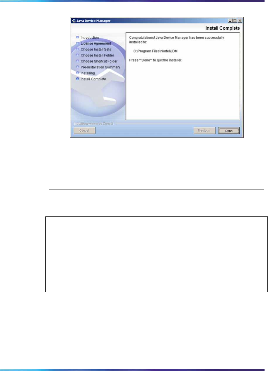
110 Getting Started with Device Manager
Install Complete dialog box
14 Click Done to exit the installation.
JDM is now installed on your machine.
—End—
Installing JDM on UNIX or Linux
ATTENTION
JDM installation procedures are standardized across all platforms. In addition,
the required Java Runtime Environment (JRE) version 1.5 is part of the JDM
installation package and does not require a separate installation. The bundled
JRE is used with this JDM only, and does not affect other Java applications on
the same system.
UNIX and Linux systems are case-sensitive. Use lower-case to specify file
names, and check to ensure that directories are entered correctly.
This section includes the following topics:
•"Minimum requirements" (page 111)
•"Installing JDM on Solaris from the CD" (page 111)
•"Installing JDM on Linux from the CD" (page 111)
•"Installing JDM on UNIX or Linux from the web" (page 112)
Nortel Ethernet Routing Switch 2500 Series
Overview — System Configuration
NN47215-500 (323162-B) 02.02 Standard
4.1 19 November 2007
Copyright © 2007, Nortel Networks
.

Installing JDM on UNIX or Linux 111
Minimum requirements
JDM supports two UNIX platforms and one Linux platform:
•a UNIX SPARC* workstation running the Sun* Solaris* 2.7, 2.8, 2.1.0.
(or higher)
•a PC running Linux Kernel 2.2 operating system (or higher)
The minimum system requirements for installing JDM on any UNIX or Linux
platform are:
•4 MB available in a temporary directory
•400 MB free in the directory where you want to install the JDM software
•512 MB DRAM
Installing JDM on Solaris from the CD
To install the JDM software to a Solaris environment from the CD, use the
following procedure:
Step Action
1Close all programs.
2Insert the software CD into your CD-ROM drive.
3Navigate to the Solaris/JDM subdirectory on the software CD.
4Run the dm_xxxx_solaris_sparc.sh file.
See "Executing the JDM installation software on UNIX or Linux"
(page 113).
—End—
Installing JDM on Linux from the CD
To install the Device Manager software to a Linux environment from the CD,
use the following procedure:
Step Action
1Close all programs.
2Insert the software CD into your CD-ROM drive.
3Navigate to the Linux/JDM subdirectory on the software CD.
4Run the jdm_xxxx_linux.sh file.
Nortel Ethernet Routing Switch 2500 Series
Overview — System Configuration
NN47215-500 (323162-B) 02.02 Standard
4.1 19 November 2007
Copyright © 2007, Nortel Networks
.

112 Getting Started with Device Manager
See "Executing the JDM installation software on UNIX or Linux"
(page 113).
—End—
Installing JDM on UNIX or Linux from the web
To install the JDM software to a UNIX (Solaris) environment from the web,
use the following procedure:
Step Action
1Go to the following URL:
www.nortel.com/support
2Select the software support page for your product.
The software page appears.
3Click the Java Device Manager version you want.
The Software Detail Information page appears.
4Download the JDM software for your operating environment to a
desired directory on your system. The software download is a
self-extracting .sh file.
Once the file transfer is complete, continue with the next step.
5Close all programs.
6Navigate to the directory on your system where you loaded the
JDM software.
7Make the installation file executable.
For the Solaris environment, make the file executable by entering:
chmod a+x dm_xxxx_solaris_sparc.sh
For the Linux environment, make the file executable by entering:
chmod a+x jdm_xxxx_linux.sh
8Run the installation file.
For the Solaris environment, run the dm_xxxx_solaris_sparc.sh file.
For the Linux environment, run the jdm_xxxx_linux.sh file.
See "Executing the JDM installation software on UNIX or Linux"
(page 113).
—End—
Nortel Ethernet Routing Switch 2500 Series
Overview — System Configuration
NN47215-500 (323162-B) 02.02 Standard
4.1 19 November 2007
Copyright © 2007, Nortel Networks
.
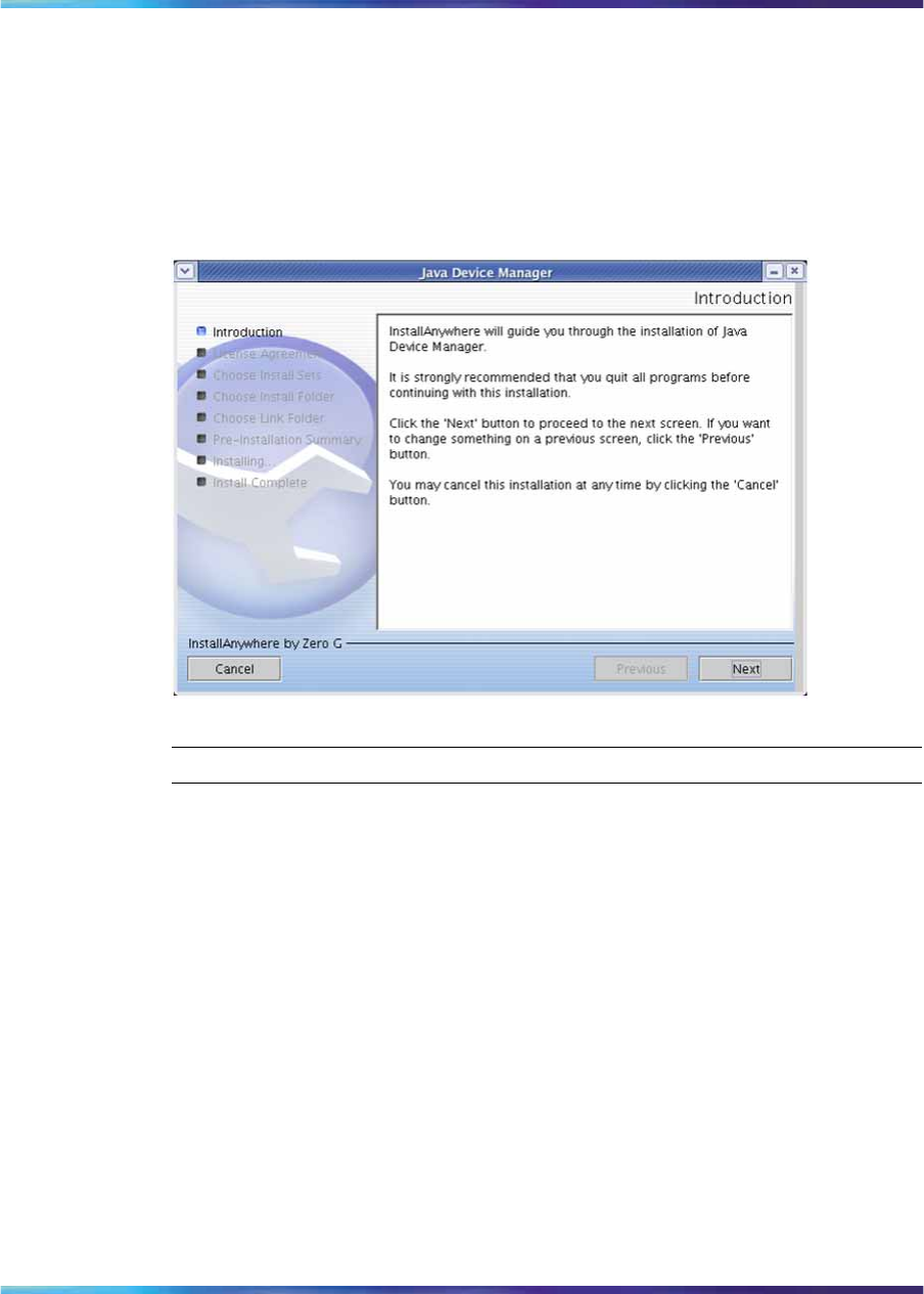
Installing JDM on UNIX or Linux 113
Executing the JDM installation software on UNIX or Linux
An install screen appears, followed by a Nortel dialog box. When the
InstallAnywhere Introduction dialog box appears, you are ready to begin
the JDM installation.
Figure 29
InstallAnywhere Introduction dialog box
Step Action
1Click Next the installation process.
The License Agreement dialog box appears.
Nortel Ethernet Routing Switch 2500 Series
Overview — System Configuration
NN47215-500 (323162-B) 02.02 Standard
4.1 19 November 2007
Copyright © 2007, Nortel Networks
.
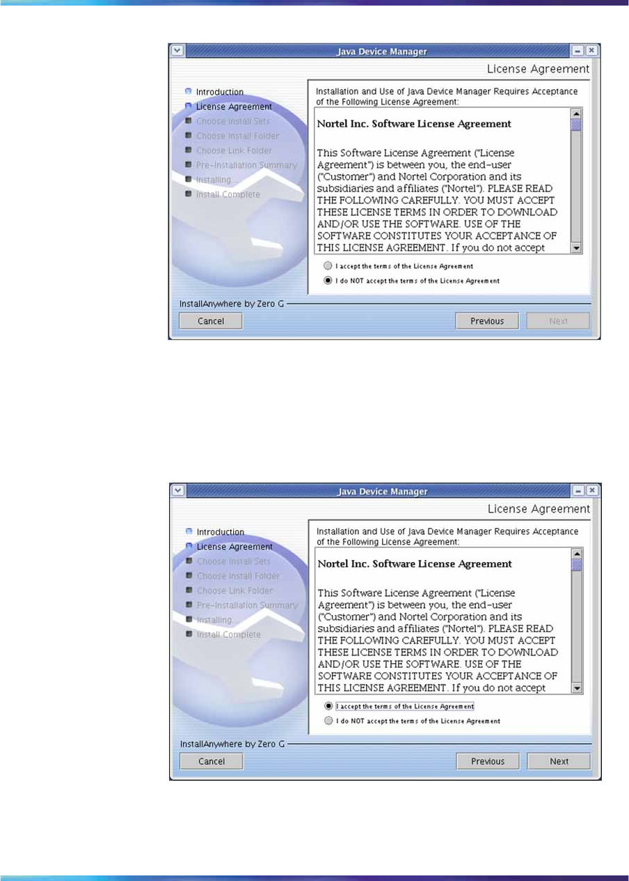
114 Getting Started with Device Manager
License Agreement dialog box
2Click I accept the terms of the License Agreement.
3Click Next.
The Choose Install Set dialog box appears.
Choose Install Set dialog box
4Do one of the following:
Nortel Ethernet Routing Switch 2500 Series
Overview — System Configuration
NN47215-500 (323162-B) 02.02 Standard
4.1 19 November 2007
Copyright © 2007, Nortel Networks
.
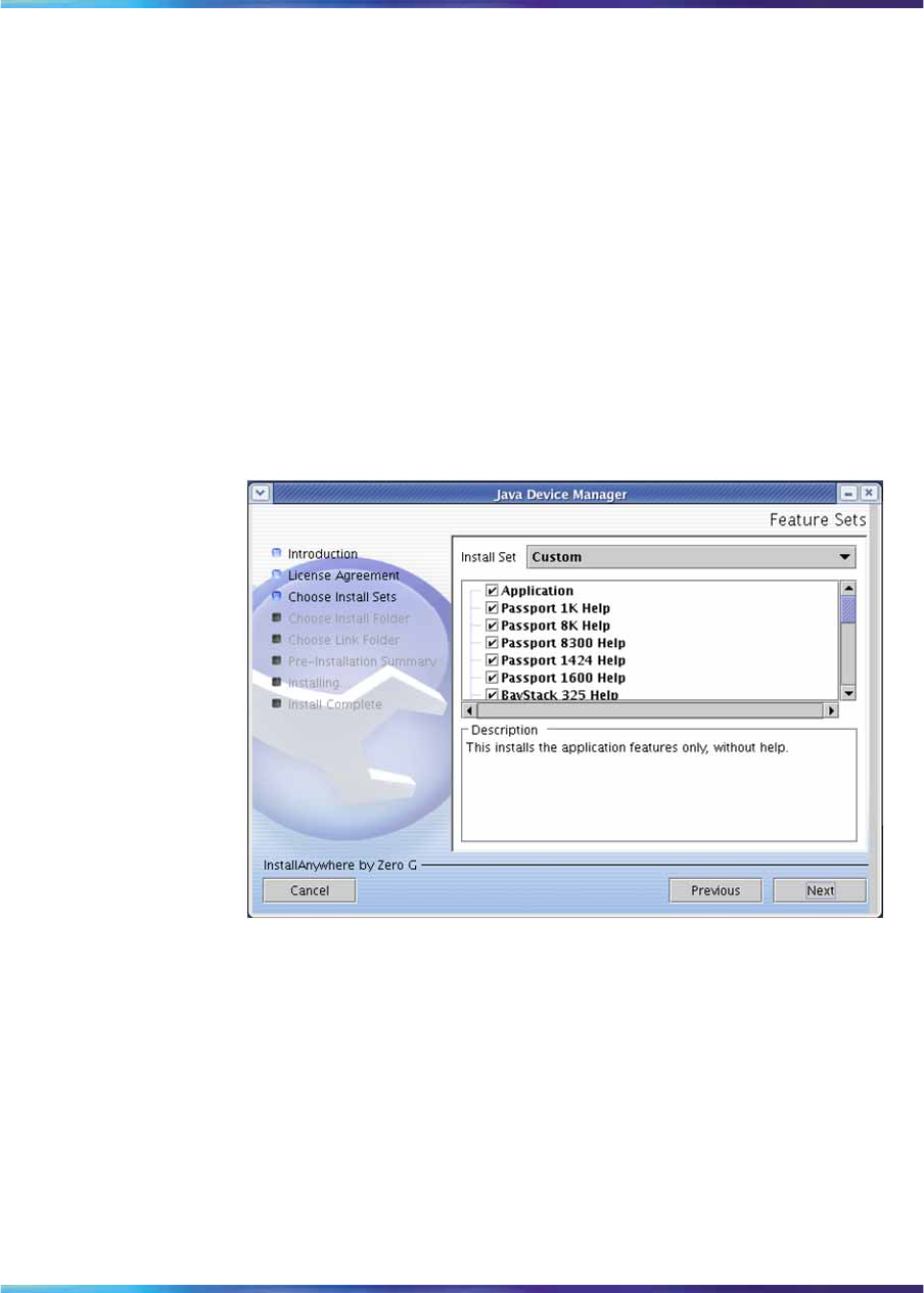
Installing JDM on UNIX or Linux 115
•Select Typical installation to install the common set features,
as well as online help.
•Select Minimal installation to select minimal features to install
(recommended for those with limited disk space).
•Select Help to install only the online help.
•Select Custom installation to customize the features prior to
installation.
5Click Next.
If you did not select Custom installation in step 4, then the Choose
Install Folder dialog box appears. See step 8.
If you selected Custom installation in step 4, then the Feature Sets
dialog box appears.
Feature Sets dialog box
6Select which features to install from the feature sets list.
7Click Next.
The Choose Install Folder dialog box appears.
Nortel Ethernet Routing Switch 2500 Series
Overview — System Configuration
NN47215-500 (323162-B) 02.02 Standard
4.1 19 November 2007
Copyright © 2007, Nortel Networks
.
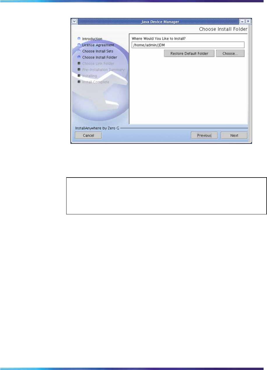
116 Getting Started with Device Manager
Choose Install Folder dialog box
8Click Restore Default Folder to use the default location for JDM, or
click Choose to select a storage path.
ATTENTION
If Device Manager is already installed on your computer, you must choose
a storage path that does not conflict with the already existing version.
9Click Next.
The Pre-Installation Summary dialog box appears.
Nortel Ethernet Routing Switch 2500 Series
Overview — System Configuration
NN47215-500 (323162-B) 02.02 Standard
4.1 19 November 2007
Copyright © 2007, Nortel Networks
.
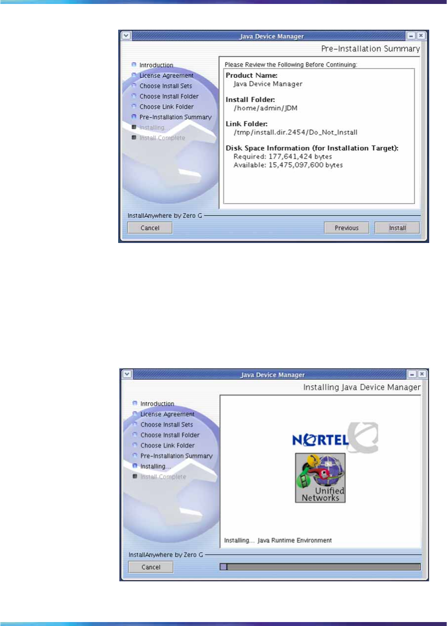
Installing JDM on UNIX or Linux 117
Pre-Installation Summary dialog box
10 Verify the folder and disk space required to install the software. If
necessary, click Previous to return to the appropriate dialog box
and make changes.
11 Click Install.
The installation process begins.
Installing Java Device Manager dialog box
Nortel Ethernet Routing Switch 2500 Series
Overview — System Configuration
NN47215-500 (323162-B) 02.02 Standard
4.1 19 November 2007
Copyright © 2007, Nortel Networks
.
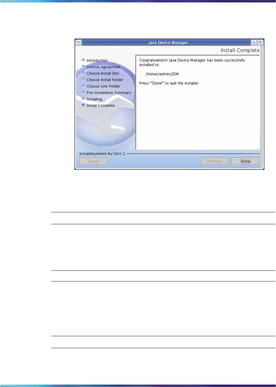
118 Getting Started with Device Manager
When the installation is complete, the Install Complete dialog box
appears.
Install Complete dialog box
12 Click Done to exit the installation.
JDM is now installed on your machine.
—End—
Removing JDM in Unix or Linux environments
In a UNIX or Linux environment, complete the following steps to remove
the existing JDM software:
Step Action
1Navigate to the directory where the JDM software is installed (for
example /JDM).
2Open the UninstallerData sub-directory.
3Run the following file: Uninstall_Java_Device_Manager.
—End—
Nortel Ethernet Routing Switch 2500 Series
Overview — System Configuration
NN47215-500 (323162-B) 02.02 Standard
4.1 19 November 2007
Copyright © 2007, Nortel Networks
.

Starting Device Manager 119
Device Manager basics
This section describes basic procedures for using the Device Manager
software. The section includes information on the following topics:
•"Starting Device Manager" (page 119)
•"Setting the Device Manager properties" (page 120)
•"Opening a device" (page 123)
•"Device Manager window" (page 126)
•"Editing objects" (page 133)
•"Working with statistics and graphs" (page 134)
•"Telnet session" (page 140)
•"Opening an SSH connection to the device" (page 140)
•"Opening the Web-based management home page" (page 141)
•"Trap log" (page 142)
•"Online Help" (page 143)
Starting Device Manager
→Do one of the following, depending upon your operating system
environment:
•In a Microsoft* Windows* environment, choose All Programs > Nortel
> Java Device Manager > DM from the Windows Start menu.
•In a UNIX environment, verify that the Device Manager installation
directory is in your search path; then enter:
./JDM
The initial Device Manager window appears.
ATTENTION
On startup, the Device Manager performs a DNS lookup for the machine on which
it is running. If the DNS lookup is slow or fails, the initial Device Manager window
may take up to 30 seconds to open.
Nortel Ethernet Routing Switch 2500 Series
Overview — System Configuration
NN47215-500 (323162-B) 02.02 Standard
4.1 19 November 2007
Copyright © 2007, Nortel Networks
.
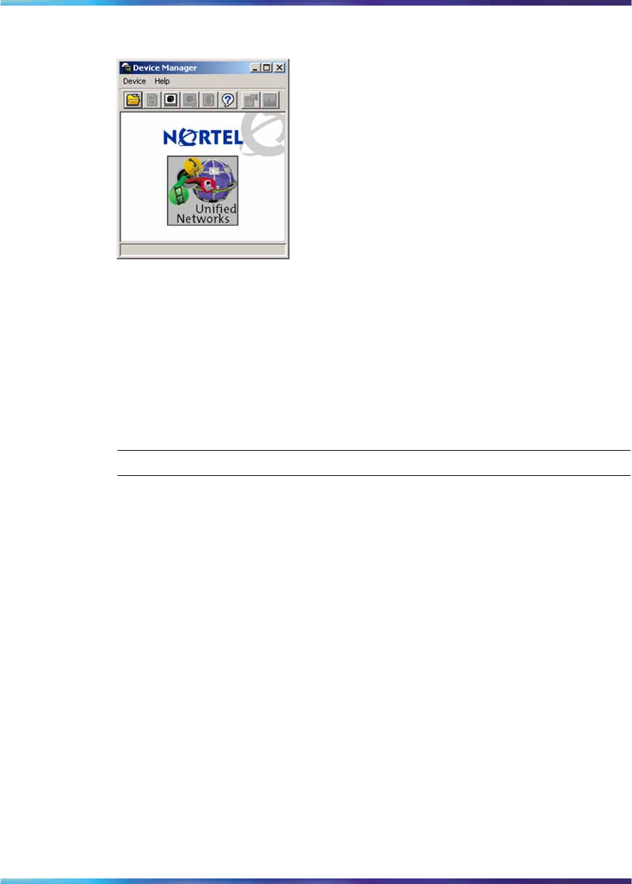
120 Getting Started with Device Manager
Figure 30
Device Manager window
Setting the Device Manager properties
The Device Manager communicates with the Ethernet Routing Switch 2500
Series using Simple Network Management Protocol (SNMP). The software
is shipped with default values set for important communication parameters,
such as the polling interval, timeout, and retry count. You can set the
parameters before you open a device to manage.
To set the Device Manager properties, use the following procedure:
Step Action
1Choose Device > Properties >Current.
The Default Properties dialog box appears.
Nortel Ethernet Routing Switch 2500 Series
Overview — System Configuration
NN47215-500 (323162-B) 02.02 Standard
4.1 19 November 2007
Copyright © 2007, Nortel Networks
.
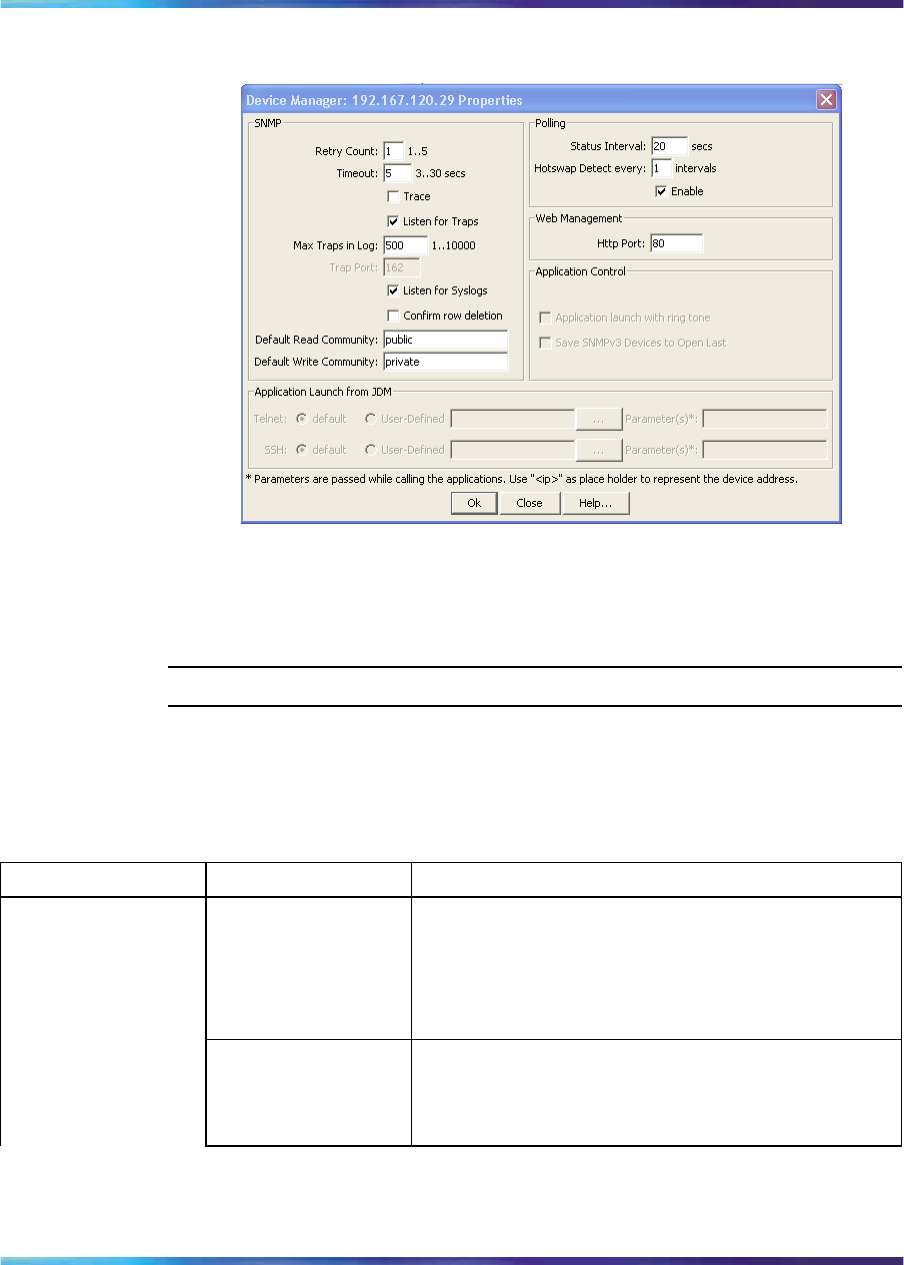
Setting the Device Manager properties 121
Figure 31
Default Properties dialog box
2Type information and select check boxes.
3Click OK.
—End—
The following table describes the Properties dialog box fields.
Table 17
Properties dialog box fields
Area Field Description
Retry Count Number of times Device Manager sends the same
polling request if a response is not returned to Device
Manager.
You may want to set this field to three or four.
Timeout Length of each retry of each polling waiting period.
When you access the device through a slow link, you
may want to increase the timeout interval and then
change the Retransmission Strategy to superlinear.
SNMP
Nortel Ethernet Routing Switch 2500 Series
Overview — System Configuration
NN47215-500 (323162-B) 02.02 Standard
4.1 19 November 2007
Copyright © 2007, Nortel Networks
.

122 Getting Started with Device Manager
Area Field Description
Trace The trace field is used to enable and disable SNMP
tracing. When Trace is selected, SNMP protocol
data units (PDUs) are displayed in the Device > Log
dialog box.
Listen for Traps When selected (enabled), Device Manager listens
for traps from the device.
Max Traps in Log The specified number of traps that may exist in the
trap log. The default is 500.
Trap Port Specifies the UDP port that Device Manager listens
to receive SNMP traps.
Listen for Syslogs When selected (enabled), Device Manager listens to
the syslog.
Confirm row deletion A dialog box displays when checked, before deleting
a row.
Default Read
Community Specifies the default read community.
Default Write
Community Specifies the default write community.
Status Interval Interval at which status information is gathered
(default is 20 seconds).
Hotswap Detect
every: The interval at which Device Manager detects the
module information. The default is 1 interval.
Polling
Enable Enables (true) or disables (false) periodic polling of
the device for updated status. If polling is disabled,
the chassis status is updated only when you click
Refresh on the Chassis tab.
Web Management Http Port Default port is 80. This field specifies the HTTP port
for the application. To access the Device Home Page
using the Web, ensure that the HTTP Port attribute
matches the switch configuration. If you change the
port number, the system prompts you with a warning
message.
Application launch
with ring tone Enabled by default, you can modify this field only
when configuring the Device Manager default
properties. You cannot modify this field when
configuring the per device properties.
Application Control
Save SNMPv3
Devices to Open
Last
Disabled by default, if you enable this field you are
prompted with a security warning message because
any user can access the device without entering the
SNMPv3 security criteria if this feature is enabled.
You can modify this field only when configuring the
Nortel Ethernet Routing Switch 2500 Series
Overview — System Configuration
NN47215-500 (323162-B) 02.02 Standard
4.1 19 November 2007
Copyright © 2007, Nortel Networks
.

Opening a device 123
Area Field Description
Device Manager default properties. You cannot
modify this field when configuring the per device
properties.
Telnet Default Telnet is the one that comes with the
operating system. To define a specific Telnet, select
User-Defined and specify the Telnet path and
parameters.
Application Launch
from JDM
SSH Default SSH is the one bundled with in the JDM.
To define a specific SSH, select User-Defined and
specify the SSH client path and parameters.
•"Opening a device" (page 123)
Opening a device
Opening a device displays the device view, a picture of the device. To
open the device view, you must enter community strings that determine the
access level granted to the device.
Table 18 "SNMP community string default values" (page 123) describes the
default access community strings for the Device Manager software.
Table 18
SNMP community string default values
Access level Description
Read-only public
Read/write private
To display the device view, use the following procedure:
Step Action
1Do one of the following:
•Choose Device > Open.
•Choose Device > Open Last by SNMPv1/v2, and select an
IP address from the list.
•For previously-opened SNMPv3-enabled devices, choose
Device > Open Last by SNMPv3, and select an IP address
from the list.
•Click the folder icon in the Device Manager window.
Nortel Ethernet Routing Switch 2500 Series
Overview — System Configuration
NN47215-500 (323162-B) 02.02 Standard
4.1 19 November 2007
Copyright © 2007, Nortel Networks
.
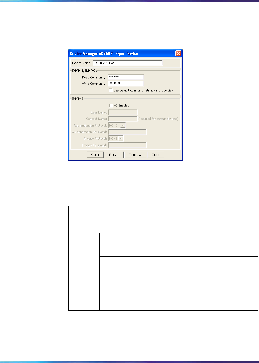
124 Getting Started with Device Manager
•Press Ctrl+O.
The Open Device dialog box appears.
Figure 32
Open Device dialog box
The following table describes the Open Device dialog box fields.
Table 19
Open Device dialog box fields
Field Description
Device Name Either an IP address or a DNS name for
the device, entered by the user.
Read Communi
ty SNMP read community string for the
device. Default is public (displayed as
******). The entry is case-sensitive.
Write Communi
ty SNMP write community string for the
device. Default is private (displayed as
*******).The entry is case-sensitive.
SNMPv1/
SNMPv2
c
Use default
community
strings in
properties
When selected, the Device Manager uses
the default community string. Set the
default community strings in Device >
Properties.
Nortel Ethernet Routing Switch 2500 Series
Overview — System Configuration
NN47215-500 (323162-B) 02.02 Standard
4.1 19 November 2007
Copyright © 2007, Nortel Networks
.

Opening a device 125
Field Description
v3 Enabled When selected (enabled), Open Device
dialog box displays SNMPv3 options.
User Name Indicates the name of the user.
Context Name Context Name string (Does not apply to
Ethernet Routing Switch 2500 Series).
Authentication
Protocol Identifies the authentication protocol
used.
Authentication
Password Specifies the current authentication
password.
Privacy Protocol Identifies the privacy protocol.
SNMPv3
Privacy Passwo
rd Specifies the current privacy password.
ATTENTION
Not all information is required for connection to a switch. If the v3 Enabled
check box is not selected, only a Device Name, Read Community,
and Write Community value are needed. If the v3 Enabled check box
is not selected, only a Device Name,Read Community, and Write
Community value are needed. If you enable Use default community
strings in properties, the Device Manager uses the default values
specified in the device properties for Read Community, and Write
Community.Ifv3 Enabled is selected, then Device Name, User Name,
Authentication Protocol, Authentication Password, Privacy Protocol,
and Privacy Password are required. If v3 Enabled is selected, then
Device Name,User Name,Authentication Protocol,Authentication
Password,Privacy Protocol, and Privacy Password are required.
Some devices require a value in Context Name.
2In the Device Name text box, type the DNS name or IP address
of the device.
3In the Read Community and Write Community text boxes, type the
appropriate community strings.
ATTENTION
To gain read/write access to a device in Device Manager, you must enter
the read/write community string for both the Read Community and Write
Community strings.
4Click Open.
Nortel Ethernet Routing Switch 2500 Series
Overview — System Configuration
NN47215-500 (323162-B) 02.02 Standard
4.1 19 November 2007
Copyright © 2007, Nortel Networks
.
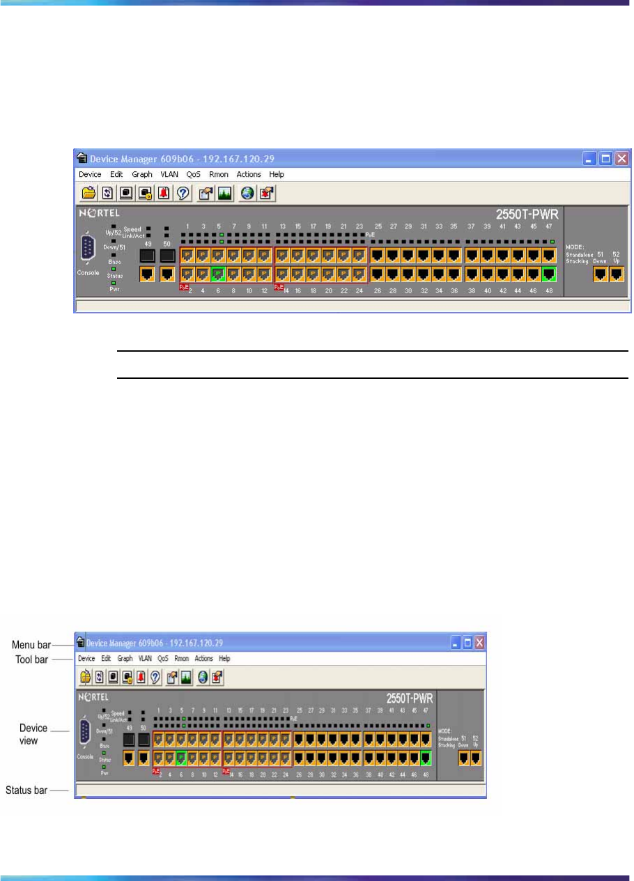
126 Getting Started with Device Manager
Device Manager automatically determines what version of software
the selected device is running and displays the appropriate Device
Manager dialog boxes.
The Device Manager window appears, showing a picture of the
device that represents the physical features of the device.
Device view
—End—
Device Manager window
The Device Manager window has the following parts:
•Menu bar
•Toolbar
•Device view
•Status bar
Figure 33
Parts of the Device Manager window
Nortel Ethernet Routing Switch 2500 Series
Overview — System Configuration
NN47215-500 (323162-B) 02.02 Standard
4.1 19 November 2007
Copyright © 2007, Nortel Networks
.

Device Manager window 127
Menu bar
Use the menu bar to set up and operate the Device Manager
Table 20 "Menu bar commands" (page 127) describes the Menu Bar
commands.
Table 20
Menu bar commands
Command Description
Device Opens the Open Device dialog box. You can also:
•Set the Properties used during a Device Manager session
•Refresh the status of the currently viewed device
•Rediscover device
•Telnet to a device
•Open an SSH connection to a device
•View SNMP traps that the Device Manager receives
•View Syslogs
•View SNMP trace logs
Edit Opens the edit dialog boxes for selected objects in the device
view. This command opens dialog boxes for managing files,
running diagnostic tests and configuring data for selected
objects. This command also lets you set security parameters,
SNTP, and SNMP v3 related configurations.
Graph Opens statistics and graphing dialog boxes for the selected
object.
VLAN Opens dialog boxes for managing VLANs, Spanning Tree Group
(STG), RSTP, MSTP, Multi-Link Trunks, and Link Aggregation
Control Protocol (LACP).
QoS Opens configuration dialog boxes for Quality of Service (QoS)
and DSCP.
RMON Opens RMON configuration and monitoring dialog boxes.
Actions Provides quick access to the Web Management Software Home
page.
Help Opens online Help topics for Device Manager and provides a
legend for the port colors in the device view.
ToolbarThe toolbar contains buttons that provide quick access to commonly used
commands and some additional actions.
Table 21 "Toolbar buttons" (page 128) describes the toolbar buttons.
Nortel Ethernet Routing Switch 2500 Series
Overview — System Configuration
NN47215-500 (323162-B) 02.02 Standard
4.1 19 November 2007
Copyright © 2007, Nortel Networks
.
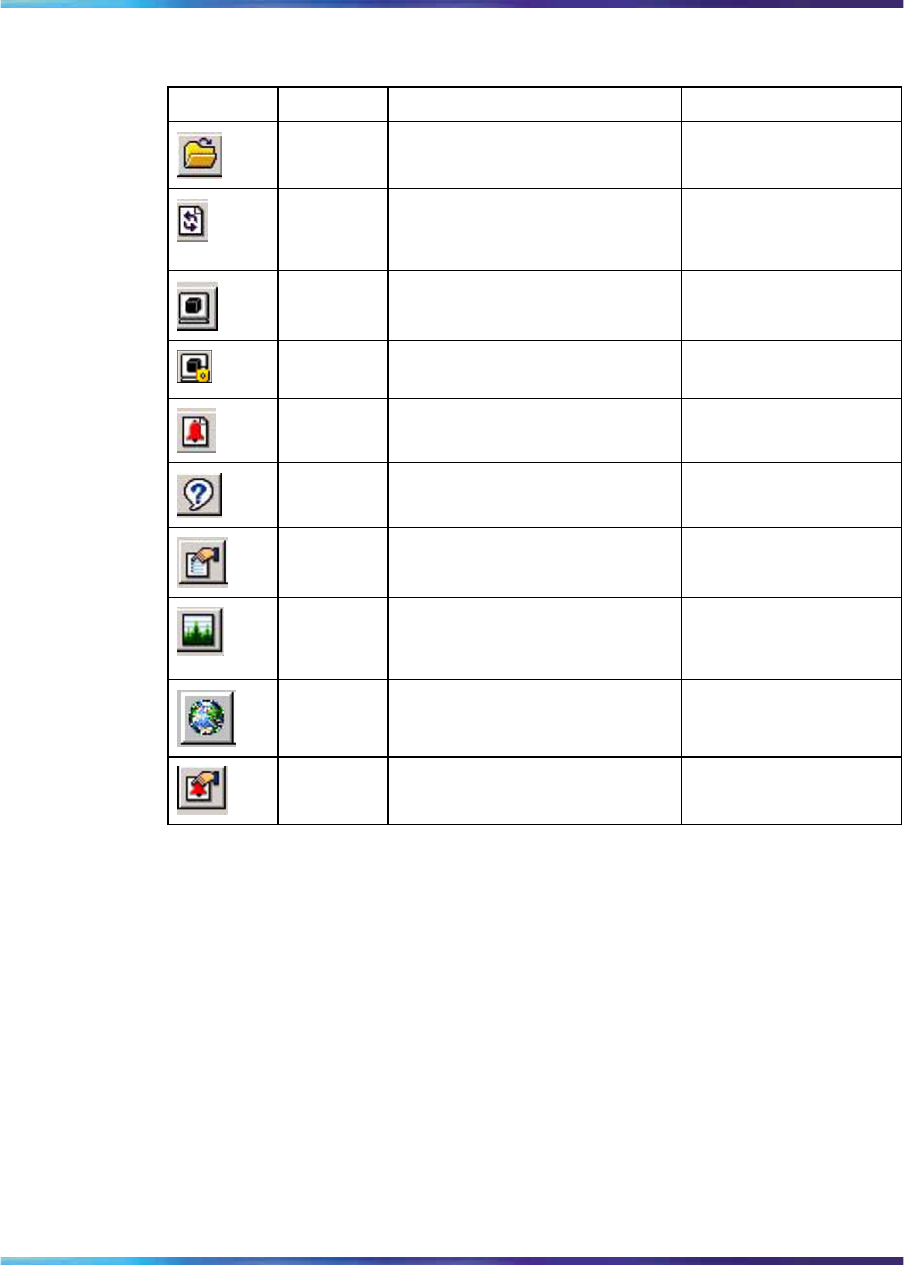
128 Getting Started with Device Manager
Table 21
Toolbar buttons
Button Name Description Menu bar equivalent
Open
Device Opens the Open Device dialog
box. Device > Open
Refresh
Device
Status
Refreshes the device view
information. Device > Refresh
Status
Telnet Opens a Telnet session. Device > Telnet
SSH Opens an SSH session. Device > SSH
Connection
Trap Log Opens the trap log. Device > Trap Log
Help Opens online Help in a Web
browser. Help > Device
Edit
Selected Displays configuration data for
the selected chassis object. Edit > Port
Graph
Selected Opens statistics and graphing
dialog boxes for the selected
object.
Graph > Port
Graph > Chassis
Home
Page Opens the Web Management
Software Home Page. Actions > Open Home
Page
Alarm
Manager Opens the Rmon Alarm
Manager. Rmon > Alarm
Manager
Device view
The device view lets you determine at a glance the operating status of the
various units and ports in your hardware configuration. You can also use the
device view to perform management tasks on specific objects.
Selecting objects
The types of objects contained in the device view are:
•A standalone switch (called a unit in the menus and dialog boxes)
•A port (including the SFP GBIC port)
Figure 34 "Objects in the device view" (page 129) shows the objects in
the device view.
Nortel Ethernet Routing Switch 2500 Series
Overview — System Configuration
NN47215-500 (323162-B) 02.02 Standard
4.1 19 November 2007
Copyright © 2007, Nortel Networks
.
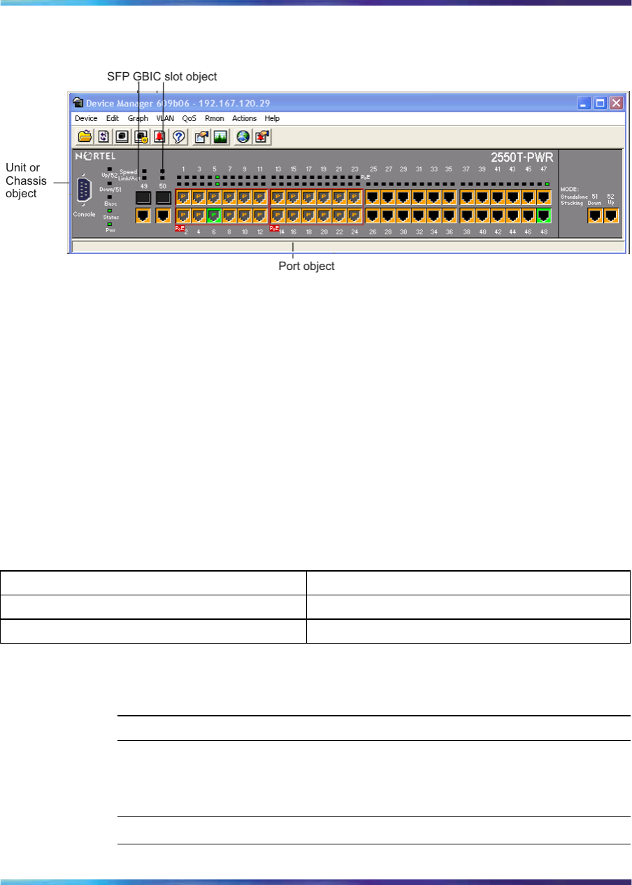
Device Manager window 129
Figure 34
Objects in the device view
Selecting a single object
To select a single object:
→Click the edge of the object.
The object is outlined in yellow, indicating that it is selected. Subsequent
activities in Device Manager refer to the selected object.
Selecting multiple objects
For instructions on selecting multiple objects (such as ports or switches),
see the following table:
Table 22
Selecting multiple objects
Object to be selected Action
To select a block of contiguous ports Drag to select the group of ports
To select all ports Choose Edit > Select > Ports
Viewing information about a GBIC port
To view information about a GBIC port, use the following procedure:
Step Action
1Select the GBIC.
2Choose Edit > Port.
—End—
Nortel Ethernet Routing Switch 2500 Series
Overview — System Configuration
NN47215-500 (323162-B) 02.02 Standard
4.1 19 November 2007
Copyright © 2007, Nortel Networks
.
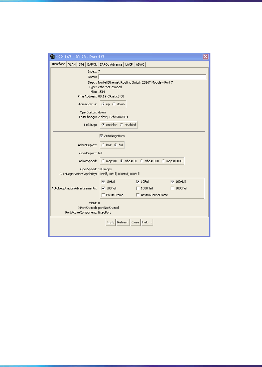
130 Getting Started with Device Manager
The Port dialog box appears with the Interface tab displayed .
The Interface tab describes the GBIC installed in the switch.
Figure 35
Interface tab
LEDs and ports
The color of LEDs in the device view is the same as the colors of the LEDs
on the physical switch. However, the device view does not show blinking
activity of the LEDs.
For a full description of the LEDs for the Ethernet Routing Switch 2500
Series, see "LED display panel" (page 27).
The ports on the device view are color coded to show port status.
Table 23 "Port color codes" (page 131) describes the status assigned to
each color.
Nortel Ethernet Routing Switch 2500 Series
Overview — System Configuration
NN47215-500 (323162-B) 02.02 Standard
4.1 19 November 2007
Copyright © 2007, Nortel Networks
.
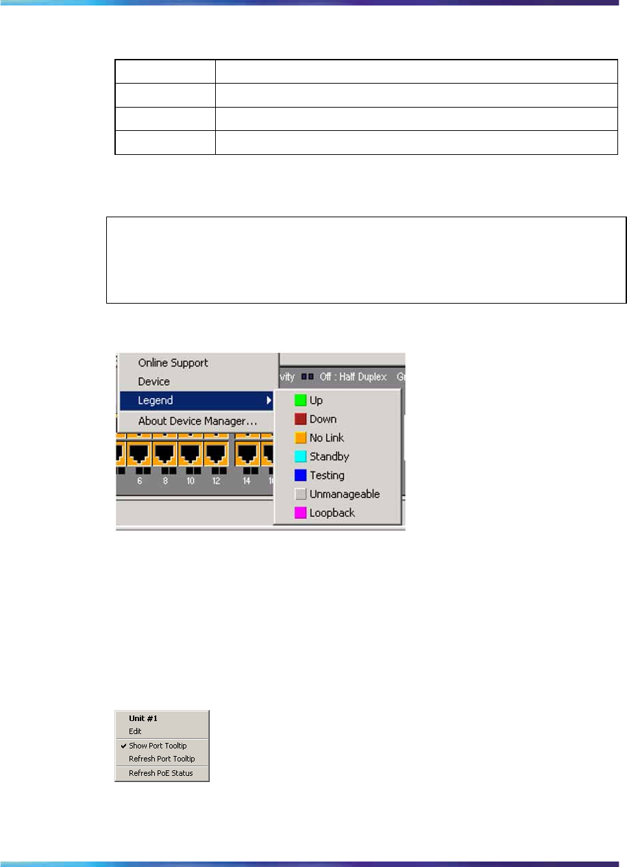
Device Manager window 131
Table 23
Port color codes
Color Description
Green Port is operating.
Red Port has been manually disabled.
Orange Port has no link.
In addition, the Help menu provides a legend that identifies the port colors
and their meanings, as shown in Figure 36 "Color port legend" (page 131).
ATTENTION
The additional colors displayed in the Device Manager legend are not applicable
to the Ethernet Routing Swith 2500 Series.
Figure 36
Color port legend
Shortcut menus
Each object in the device view has a shortcut menu that appears when
you right-click a selected object. The switch unit shortcut menu provides
access to basic hardware information about the switch and to the graphing
dialog boxes for the switch.
Figure 37
Switch unit shortcut menu
Table 24 "Switch unit shortcut menu command" (page 132) describes the
Switch unit shortcut menu command on the switch unit shortcut menu.
Nortel Ethernet Routing Switch 2500 Series
Overview — System Configuration
NN47215-500 (323162-B) 02.02 Standard
4.1 19 November 2007
Copyright © 2007, Nortel Networks
.
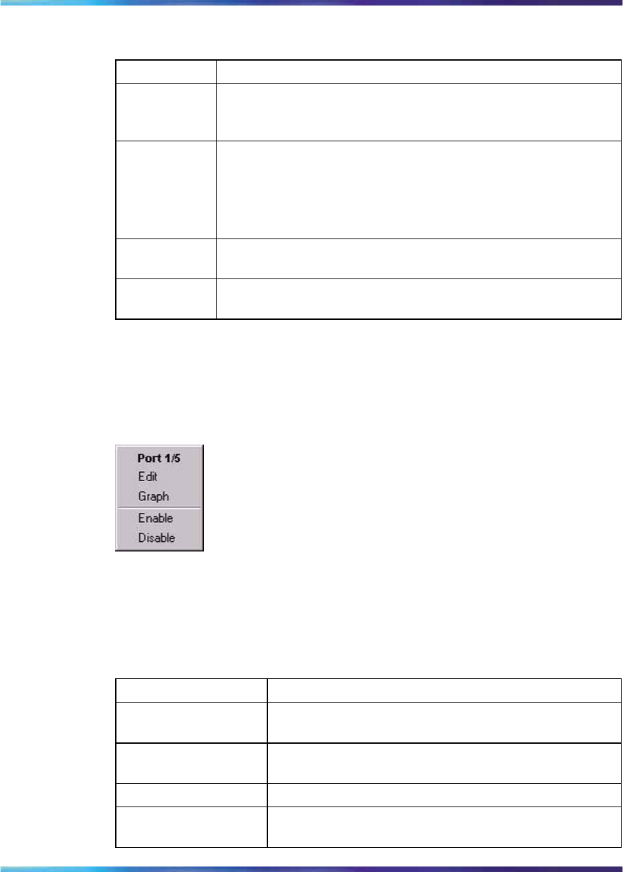
132 Getting Started with Device Manager
Table 24
Switch unit shortcut menu command
Command Description
Edit Opens a dialog box that provides basic hardware information
about the switch and lets you set the Rate Limiting configuration
for the switch unit.
Show Port
Tooltip Indicates that the tooltip function is active. When unchecked,
the tooltip function is disabled.
A Tooltip is a descriptive text box that appears when the mouse
pointer is held over a port.
Refresh Port
Tooltip Refreshes the tooltip information.
Refresh PoE
Status Refreshes the status for PoE ports.
The port shortcut menu provides a faster path for editing and graphing a
single port; however, you can access the same options using the menu
bar or the toolbar.
Figure 38
Port shortcut menu
Table 25 "Port shortcut menu commands" (page 132) describes the
commands on the port shortcut menu.
Table 25
Port shortcut menu commands
Command Description
Edit Opens a dialog box that lets you set operating
parameters for the port.
Graph Opens a dialog box that displays statistics for the port
and lets you display the statistics as a graph.
Enable Administratively brings a port up.
Disable Administratively shuts down a port. The color of the port
changes to red in the device view.
Nortel Ethernet Routing Switch 2500 Series
Overview — System Configuration
NN47215-500 (323162-B) 02.02 Standard
4.1 19 November 2007
Copyright © 2007, Nortel Networks
.
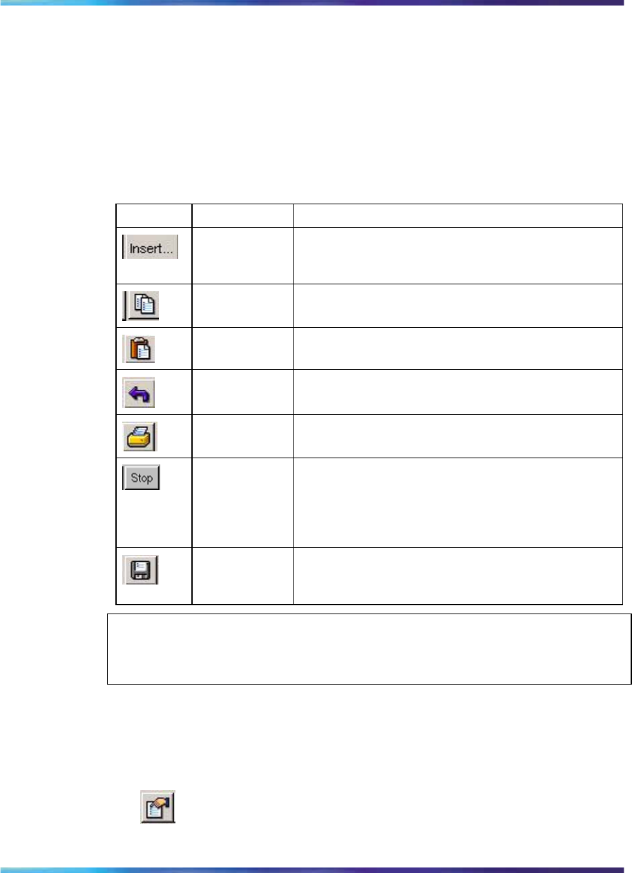
Editing objects 133
Status bar
The status bar displays error and informational messages from the software
application. These messages are not related to the device being managed.
Using the buttons in Device Manager dialog boxes
Table 26 "Device Manager buttons" (page 133) describes buttons in Device
Manager dialog boxes.
Table 26
Device Manager buttons
Button Name Description
Insert Opens a dialog box to create a new entry for a table;
then from the dialog box, inserts the new entry in
the table.
Copy Copies selected cells from a table.
Paste Pastes copied values to a currently selected table
cell.
Reset
Changes Causes changed (but not applied) fields to revert
to their previous values.
Print Table or
Print Graph Prints the table or graph that is displayed.
Stop/Refresh Stops the current action (compiling, saving, and so
forth). If you are updating or compiling a large data
table, the Refresh button changes to a Stop button
while this action is taking place. Clicking the Stop
button interrupts the polling process.
Export Data Exports information to a file you specify. You can
then import this file into a text editor or spreadsheet
for further analysis.
ATTENTION
Not all buttons appear in all the dialog boxes.
Editing objects
You can edit objects and values in the Device Manager device view in the
following ways:
•Select an object on the toolbar, click the Edit Selected button.
Nortel Ethernet Routing Switch 2500 Series
Overview — System Configuration
NN47215-500 (323162-B) 02.02 Standard
4.1 19 November 2007
Copyright © 2007, Nortel Networks
.

134 Getting Started with Device Manager
The Edit dialog box appears for that object.
•From a switch or port shortcut menu, choose Edit. The Edit dialog
box appears for that object.
When you change the value in a box, the changed value is displayed in
bold. However, changes are not applied to the running configuration until
you click Apply.
ATTENTION
Many dialog boxes contain a Refresh button. After you apply changes to fields,
click Refresh to display the new information in the dialog box.
Working with statistics and graphs
Device Manager tracks a wide range of statistics for the switch and each
port. You can view and graph statistics for a single object or multiple objects.
For information about the statistics tracked for the switch and ports, see
"Statistics for single and multiple objects" (page 137) and to the Nortel
Ethernet Routing Switch 2500 Series Performance Management — System
Monitoring (NN47215-502).
This section describes the types of statistics and graphs available, the graph
dialog boxes, and the procedure for creating a graph.
Types of statistics
The data tables in the statistics dialog boxes list the counters, or categories
of statistics being gathered, for the specified object. For example, the
categories for ports include Interface, Ethernet Errors, Bridge, and Rmon.
Each category can be associated with six types of statistics.
Table 27 "Types of statistics" (page 134) describes the types of statistics
that are available.
Table 27
Types of statistics
Statistic Description
AbsoluteValue The total count since the last time counters were reset. A
system reboot resets all counters.
Cumulative The total count since the statistics window was first opened.
The elapsed time for the cumulative counter is displayed at the
bottom of the graph window.
Average The cumulative count divided by the cumulative elapsed time.
Minimum The minimum average for the counter for a given polling
interval over the cumulative elapsed time.
Nortel Ethernet Routing Switch 2500 Series
Overview — System Configuration
NN47215-500 (323162-B) 02.02 Standard
4.1 19 November 2007
Copyright © 2007, Nortel Networks
.
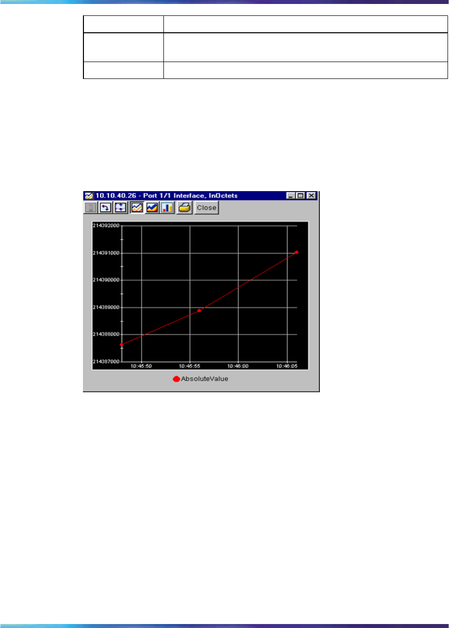
Working with statistics and graphs 135
Statistic Description
Maximum The maximum average for the counter for a given polling
interval over the cumulative elapsed time.
LastValue The average for the counter over the last polling interval.
Types of graphs
With Device Manager, you can create line, area, bar, and pie graphs. Figure
39 "Line graph" (page 135),Figure 40 "Area graph" (page 136),Figure
41 "Bar graph" (page 136), and Figure 42 "Pie graph" (page 137) provide
examples of different types of graphs.
Figure 39
Line graph
Nortel Ethernet Routing Switch 2500 Series
Overview — System Configuration
NN47215-500 (323162-B) 02.02 Standard
4.1 19 November 2007
Copyright © 2007, Nortel Networks
.
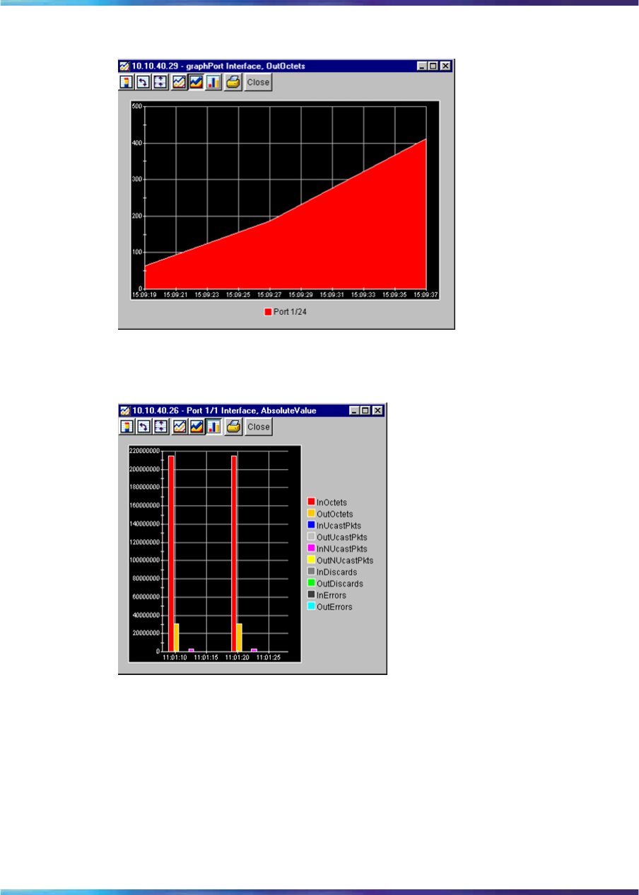
136 Getting Started with Device Manager
Figure 40
Area graph
Figure 41
Bar graph
Nortel Ethernet Routing Switch 2500 Series
Overview — System Configuration
NN47215-500 (323162-B) 02.02 Standard
4.1 19 November 2007
Copyright © 2007, Nortel Networks
.
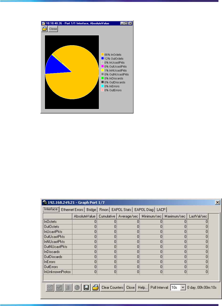
Working with statistics and graphs 137
Figure 42
Pie graph
•"Statistics for single and multiple objects" (page 137)
•"Viewing statistics as graphs" (page 138)
Statistics for single and multiple objects
Statistics for a selected object or objects are displayed in the statistics
dialog box.
The dialog box for a single object shows all six types of statistics for each
counter.
Figure 43
Interface statistics for a single port
Nortel Ethernet Routing Switch 2500 Series
Overview — System Configuration
NN47215-500 (323162-B) 02.02 Standard
4.1 19 November 2007
Copyright © 2007, Nortel Networks
.
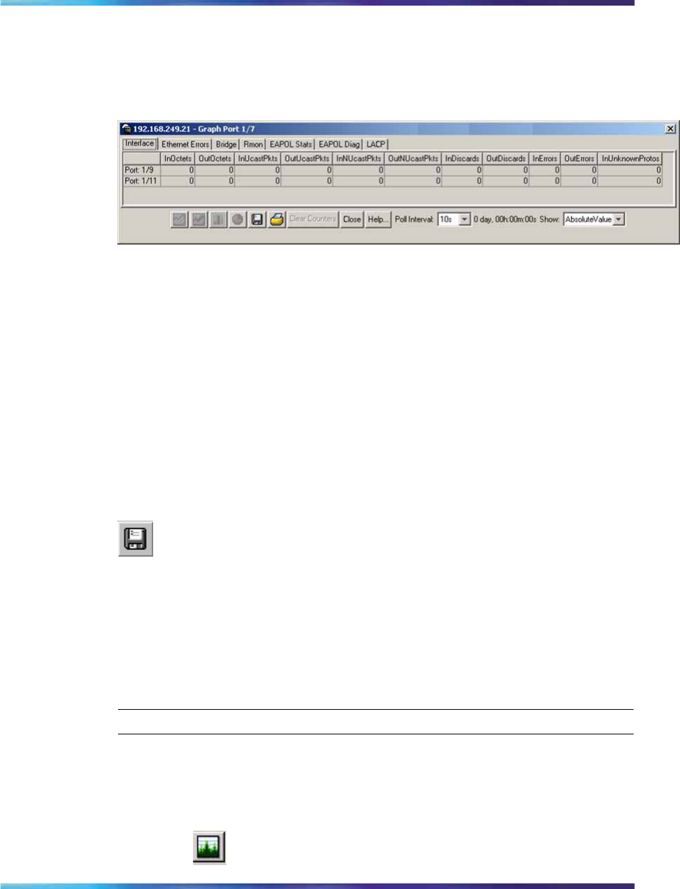
138 Getting Started with Device Manager
The statistics dialog box for multiple objects shows a single type of statistics
for the selected objects. For example, Figure 44 "Interface statistics for
multiple ports" (page 138) shows LastValue statistics for the selected ports.
Figure 44
Interface statistics for multiple ports
To change the type of statistics displayed, select a different type from the
show list at the bottom of the dialog box.
The statistics are updated based on the poll interval shown at the bottom of
the dialog box. You can select a different polling interval.
Buttons for bar, pie, and line graphs are located at the bottom of a statistics
dialog box.
See the next section, "Viewing statistics as graphs" (page 138),for
instructions to use these buttons.
You can export the statistics to a tab-separated file format and import the
file into other applications. To export the information, use the Export Data
button below the table.
•"Types of statistics" (page 134)
•"Viewing statistics as graphs" (page 138)
Viewing statistics as graphs
To create a graph for an object, use the following procedure:
Step Action
1Select the object or objects to be graphed.
2Do one of the following:
•On the toolbar, click Graph Selected.
Nortel Ethernet Routing Switch 2500 Series
Overview — System Configuration
NN47215-500 (323162-B) 02.02 Standard
4.1 19 November 2007
Copyright © 2007, Nortel Networks
.
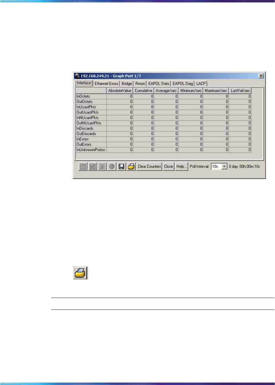
Working with statistics and graphs 139
•From the shortcut menu for the object, choose Graph.
•From the main menu, choose Graph > Chassis or Graph > Port.
A statistics dialog box appears with tabs for different categories of
statistics for the selected object.
Figure 45
Statistics dialog box for a port
3Select a tab for the group of statistics you want to view.
4On the displayed data table, click and drag to select the cells you
want to graph. (They must be in the same row or column.)
5Click one of the graph buttons at the bottom of the dialog box
A graph dialog box appears for the selected graph type.
6To print a copy of the graph, click Print.
—End—
Buttons at the top of the graph dialog boxes for line, area, and bar graphs
allow you to change the orientation of the graph, change the scale, or
change the graph type.
The following table describes the buttons in the graph dialog boxes.
Nortel Ethernet Routing Switch 2500 Series
Overview — System Configuration
NN47215-500 (323162-B) 02.02 Standard
4.1 19 November 2007
Copyright © 2007, Nortel Networks
.
140 Getting Started with Device Manager
Table 28
Graph dialog box buttons
Button Name Description
Stacked "Stacks" data quantities instead of displaying them
side-by-side.
Horizontal Rotates the graph 90 degrees.
Log Scale Changes the scale of the x-axis (of an unrotated graph)
from numeric to logarithmic.
Line Chart Converts an area graph or bar graph to a line graph.
Area Chart Converts a line graph or bar graph to an area graph.
Bar Chart Converts a line graph or area graph to a bar graph.
Pie Chart Converts a line graph or area graph to a pie chart.
Telnet session
From Device Manager, you can initiate a Telnet session to the switch you
are currently accessing.
To Telnet to a switch:
→Do one of the following:
•From the Device Manager main menu, choose Device> Telnet.
•On the toolbar, click the Telnet button.
A Telnet window to the switch appears.
Opening an SSH connection to the device
From Device Manager, you can initiate a Secure Shell (SSH) connection to
the the switch you are currently accessing.
To open an SSH connection to a device, use the following procedure:
Nortel Ethernet Routing Switch 2500 Series
Overview — System Configuration
NN47215-500 (323162-B) 02.02 Standard
4.1 19 November 2007
Copyright © 2007, Nortel Networks
.
Opening the web-based management home page 141
→Do one of the following:
•From the Device Manager main menu, choose Device > SSH
Connection.
•On the toolbar, click the SSH button.
An SSH window to the device appears.
ATTENTION
The SSH connection is established only when the device is SSH capable and
enabled. For more information on SSH connections, see Nortel Ethernet Routing
Switch 2500 Series Security — Configuration and Management (NN47215-505).
Opening the web-based management home page
From the Device Manager, you can access the web-based management
home page.
To open the web-based management home page, use the following
procedure:
→Do one of the following:
•From the Device Manager main menu, choose Actions > Open
Home Page.
•On the toolbar, click the Open Home Page button.
The web-based management home page appears.
Nortel Ethernet Routing Switch 2500 Series
Overview — System Configuration
NN47215-500 (323162-B) 02.02 Standard
4.1 19 November 2007
Copyright © 2007, Nortel Networks
.
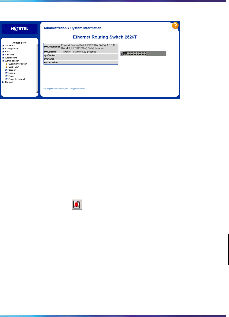
142 Getting Started with Device Manager
Figure 46
Web-based management home page
Trap log You can configure an Ethernet Routing Switch 2500 Series to send SNMP
generic traps. When the Device Manager is running, any traps received are
recorded in the trap log. You set the maximum number of entries in the trap
log using the Properties dialog box ("DCAM-6270493" (page 120)). The
default number of trap log entries is 500.
To view the trap log, use the following procedure:
→Do one of the following:
•On the toolbar, click the Trap Log button.
•From the Device Manager Main Menu, choose Device > Trap Log.
ATTENTION
When you operate Device Manager from a UNIX platform, you must be logged in
as root in order to receive traps.
Device Manager receives traps on port 162. If this port is being used by
another application, you cannot view the trap log until the other application
is disabled and Device Manager is restarted.
Nortel Ethernet Routing Switch 2500 Series
Overview — System Configuration
NN47215-500 (323162-B) 02.02 Standard
4.1 19 November 2007
Copyright © 2007, Nortel Networks
.

Online Help 143
By default, traps are sent in SNMP V2c format. However, if you are using an
older network management system (NMS), one that supports only SNMP
V1 traps, you can specify the traps to be sent in V1 format.
For more information about traps and trap receivers, see Nortel Ethernet
Routing Switch 2500 Series Security — Configuration and Management
(NN47215-505).
Online Help Online Help in Device Manager is context-sensitive. You use a Web browser
to display online Help. The Web browser should launch automatically
when you click the Help button. If the Help topic you are accessing is not
displayed in your browser, exit the existing browser session and click the
Help button again.
If the Web browser does not launch, the default locations of the Help files
are the directories listed as follows:
Table 29 "Help file locations" (page 143) describes the Help file locations.
Table 29
Help file locations
Platform Default path
Windows 95, Windows 98, Windows
NT, Windows 2000, Windows XP,
Windows Vista, UNIX
<JDM Installation directory>/help/plat
ypus/v410.zip.
After you unzip the file, <JDM
Installation directory>/help/
platypus/v410/help.html, the help.html
is the home page for the online help.
Nortel Ethernet Routing Switch 2500 Series
Overview — System Configuration
NN47215-500 (323162-B) 02.02 Standard
4.1 19 November 2007
Copyright © 2007, Nortel Networks
.

144 Getting Started with Device Manager
Nortel Ethernet Routing Switch 2500 Series
Overview — System Configuration
NN47215-500 (323162-B) 02.02 Standard
4.1 19 November 2007
Copyright © 2007, Nortel Networks
.

145
Using the Web-based management
interface
This chapter describes the requirements for using the Web-based
management interface and how to use it as a tool to configure your Ethernet
Routing Switch 2500 Series.
Requirements
To use the web-based management interface, you need the following items:
•A computer connected to a network port that is a member of the
management VLAN
•One of the following Web browsers installed on the computer:
— Microsoft* Internet Explorer, version 4.1 or later on Windows 95,
Windows 98, Windows 2000, Windows NT*, Windows XP*, or
Windows Vista
— Netscape Navigator*, version 4.51 or later on Windows 95, Windows
98, Windows 2000, Windows NT, Windows XP, Windows Vista, and
UNIX*
•IP address of the Ethernet Routing Switch 2500 Series
ATTENTION
The Web pages of the web-based management interface may load at different
speeds depending on the Web browser you use.
In order to use the Ethernet Routing Switch 2500 Series web-based management
functionality, such as downloading software, you must connect your TFTP server
to an Ethernet Routing Switch 2500 Series.
For instructions to set the IP address of the switch, see "ip address
command" (page 178).
Nortel Ethernet Routing Switch 2500 Series
Overview — System Configuration
NN47215-500 (323162-B) 02.02 Standard
4.1 19 November 2007
Copyright © 2007, Nortel Networks
.
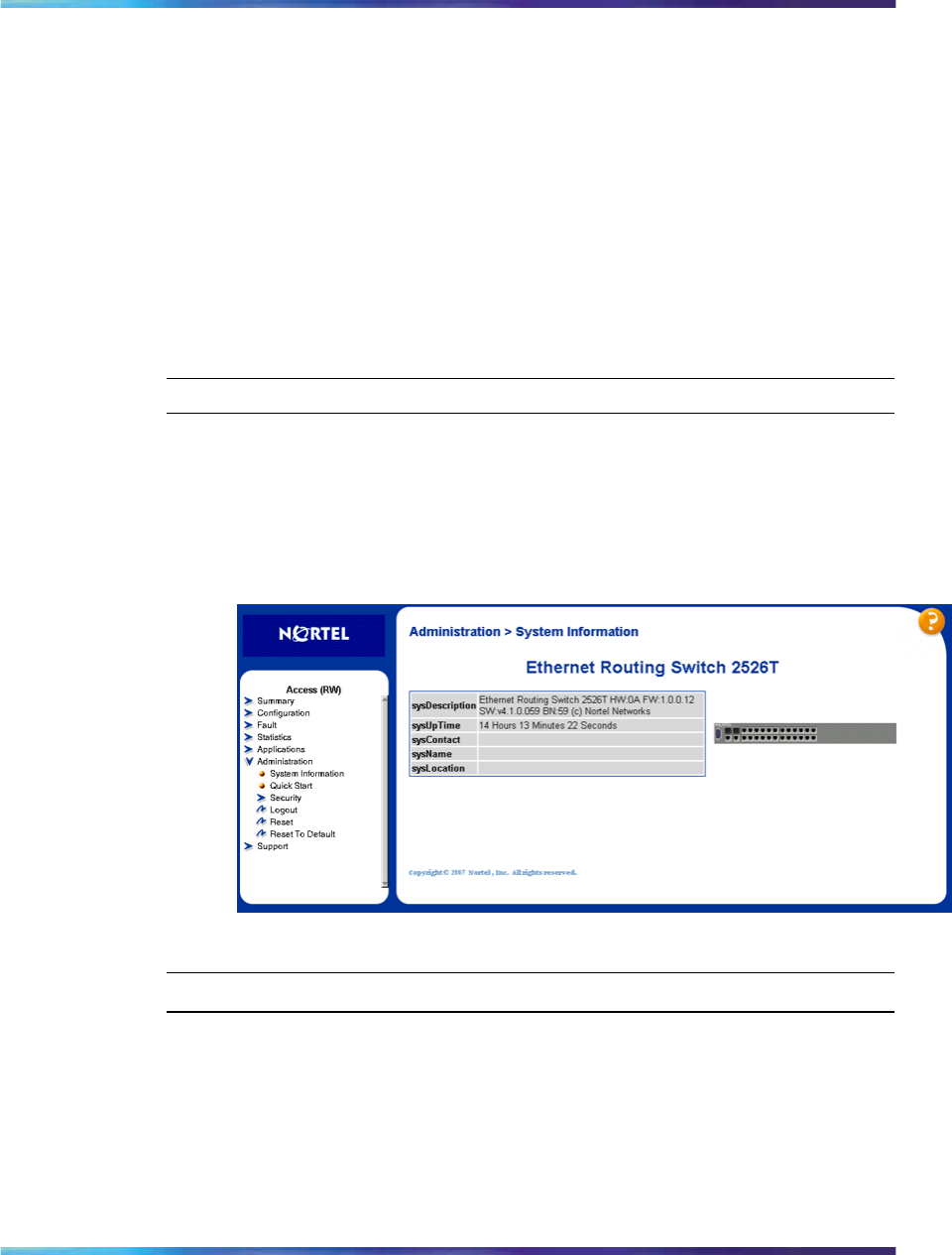
146 Using the Web-based management interface
Access to the Web management interface for the switch is enabled by
default. You can configure access to the interface using the CLI. For
information about enabling Web access, see Nortel Ethernet Routing Switch
2500 Series Security — Configuration and Management (NN47215-505).
Logging in to the web-based management interface
Before you log in to the web-based management interface, use the CLI to
verify the VLAN port assignments and to ensure that your switch CPU and
computer are assigned to the same VLAN. If the devices are not connected
to the same VLAN, the IP address cannot display the home page.
To log in to the web-based management interface, use the following
procedure:
Step Action
1Start your Web browser.
2In the address bar, type the IP address for your host switch, for
example, http://192.168.151.175, and press Enter.
The home page appears.
Web-based management interface home page
—End—
Network security does not exist the first time you access the embedded
Web server. The system administrator must create access parameters and
passwords to protect the integrity of your network configuration(s). For more
information, see Nortel Ethernet Routing Switch 2500 Series Security —
Configuration and Management (NN47215-505).
Nortel Ethernet Routing Switch 2500 Series
Overview — System Configuration
NN47215-500 (323162-B) 02.02 Standard
4.1 19 November 2007
Copyright © 2007, Nortel Networks
.
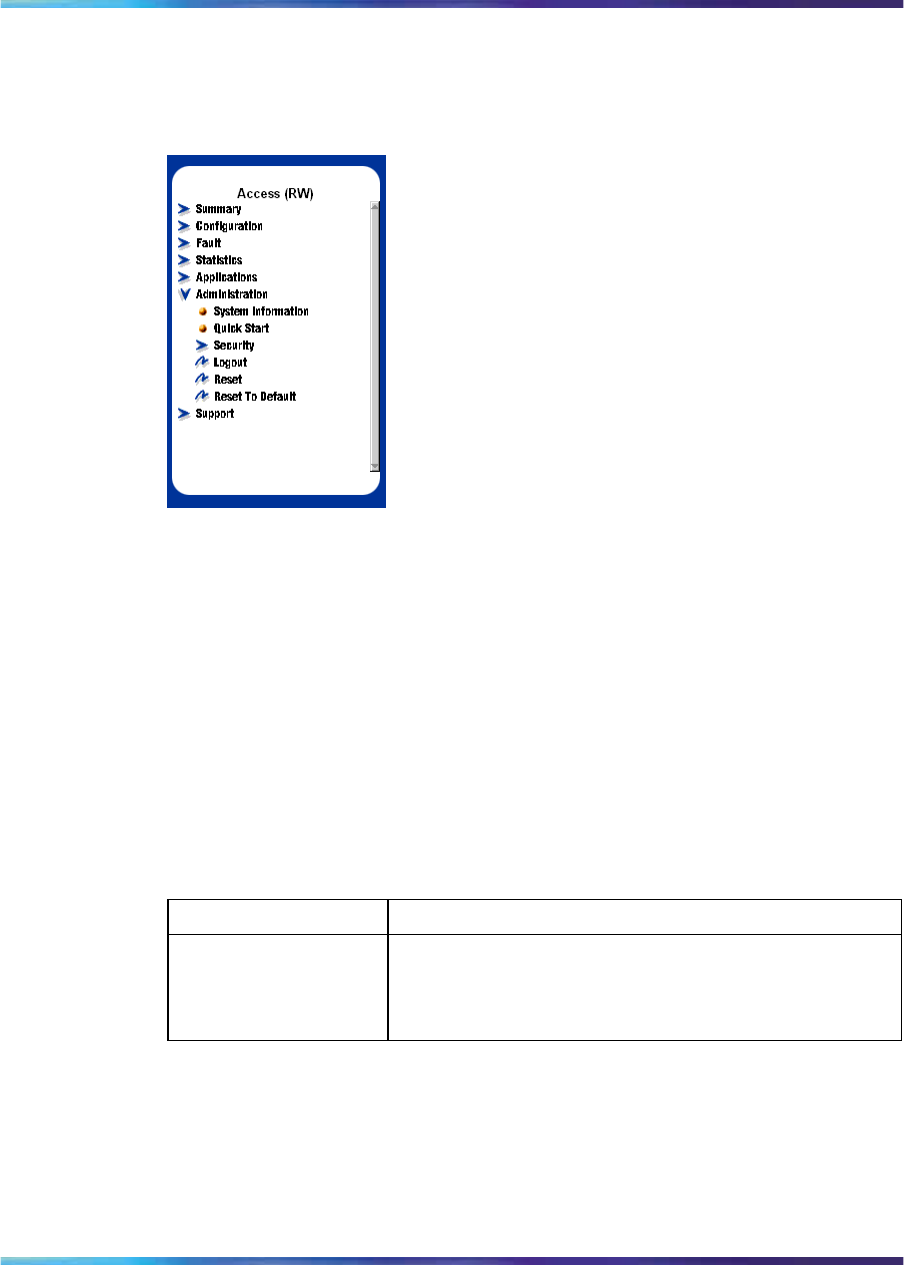
Logging in to the web-based management interface 147
Menu The menu is the same for all pages. It contains a list of seven main headings.
Figure 47
Menu
To navigate the web-based management interface menu, click a menu
title and then click one of its options. When you click an option, the
corresponding page appears.
The first six headings provide options for viewing and configuring switch
parameters. The Support heading provides options to open the online Help
file and the Nortel Web site.
Table 30 "Main headings and options" (page 147) lists the main headings in
the Web-based management interface and their associated options.
Table 30
Main headings and options
Main menu titles Option
Summary Stack Information
Switch Information
Identify Unit Numbers
Stack Numbering
Nortel Ethernet Routing Switch 2500 Series
Overview — System Configuration
NN47215-500 (323162-B) 02.02 Standard
4.1 19 November 2007
Copyright © 2007, Nortel Networks
.

148 Using the Web-based management interface
Main menu titles Option
Configuration IP
System
Remote Access
SNMPv1
SNMPv3
SNMP Trap
MAC Address
Find MAC Address
Port Management
High Speed Flow Control
Software Download
License Download
ASCII Config Download
Configuration File
Console/Comm Port
Fault RMON Threshold
RMON Event Log
System Log
Statistics Port
Port Error Summary
Interface
Ethernet Errors
Transparent Bridging
RMON Ethernet
RMON History
Applications Port Mirroring
Rate Limiting
EAPOL Security
MAC Address Security
IGMP
VLAN
Spanning Tree
Multilink Trunk
Link Aggregation
QoS
ADAC
Administration System Information
Quick Start
Security
Logout
Reset
Reset to Default
Support Help
Release Notes
Manuals
Upgrade
Nortel Ethernet Routing Switch 2500 Series
Overview — System Configuration
NN47215-500 (323162-B) 02.02 Standard
4.1 19 November 2007
Copyright © 2007, Nortel Networks
.
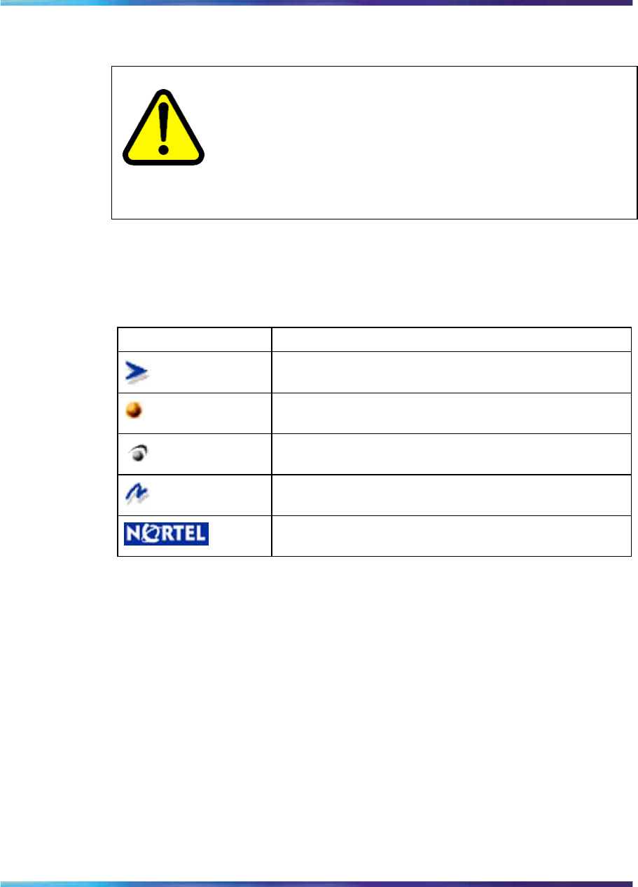
Logging in to the web-based management interface 149
Tools are provided in the menu to assist you in navigating the web-based
management interface.
CAUTION
Web browser capabilities such as page bookmarking, refresh,
and page forward and page back, function as they would in any
other Web site. However, these capabilities do not enhance the
functionality of the web-based management interface. Nortel
recommends that you use only the navigation tools provided in the
management interface.
Table 31 "Menu icons" (page 149) describes the icons that appear on the
menu.
Table 31
Menu icons
Button or icon Description
This icon identifies a menu title. Click on this icon to
display its options.
This icon identifies a menu title option. Click on this icon
to display the corresponding page.
This icon identifies a menu title option with a hyperlink
to related pages.
This icon is linked to an action, for example, logout,
reset, or reset to system defaults.
Clicking on the Nortel logo opens the corporate home
page in a new Web browser.
Management page
When you click a menu option, the corresponding management page
appears. Figure 48 "Console page" (page 150) shows the page displayed
for the Administration > Security > Console option.
Nortel Ethernet Routing Switch 2500 Series
Overview — System Configuration
NN47215-500 (323162-B) 02.02 Standard
4.1 19 November 2007
Copyright © 2007, Nortel Networks
.
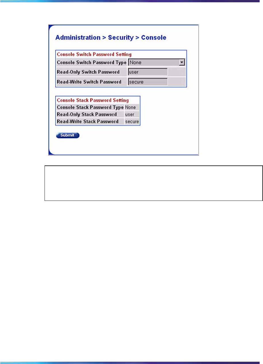
150 Using the Web-based management interface
Figure 48
Console page
ATTENTION
The Console Stack Password Setting section is active only when the switch is
in the stack mode.
A page is composed of one or more of the following elements:
•Tables and input forms
The gray cells in a page are display only, and white cells are input fields.
•Check boxes
You enable or disable a selection by clicking a check box. When a check
mark is displayed in the box, that selection is enabled. You disable a
selection by clicking the checked box.
•Icons and buttons
Icons and buttons perform an action concerning the displayed page or
the switch. Some pages include a button that opens another page or
updates the values shown on the current page. Some pages include
icons that initiate an action, such as reformatting the current displayed
data as a bar or pie chart.
Table 32 "Page icons" (page 151) describes the icons that you use to modify
information in a statistical table.
Nortel Ethernet Routing Switch 2500 Series
Overview — System Configuration
NN47215-500 (323162-B) 02.02 Standard
4.1 19 November 2007
Copyright © 2007, Nortel Networks
.
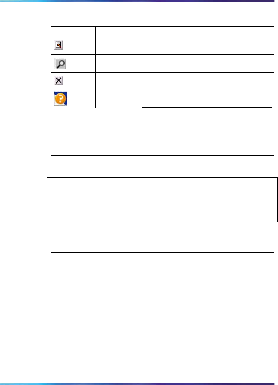
Viewing stack information 151
Table 32
Page icons
Icon Name Description
Modify Accesses a modification page for the selected
row.
View Accesses a view only statistics page for the
selected row.
Delete Deletes a row.
Help Accesses the Help menu in a new Web browser.
ATTENTION
Text within a table that is underlined and
highlighted in blue and is a hyperlink to a
related management page.
Viewing stack information
ATTENTION
The Embedded Web Server automatically detects the operational mode of your
system. If the system is in stand-alone mode, the Stack Information page option
is not listed in the menu.
To view stack information:
Step Action
1Open the Stack Information screen by selecting Summary > Stack
Information from the menu. This screen is illustrated in Figure 49
"Stack Information page" (page 152).
—End—
Nortel Ethernet Routing Switch 2500 Series
Overview — System Configuration
NN47215-500 (323162-B) 02.02 Standard
4.1 19 November 2007
Copyright © 2007, Nortel Networks
.
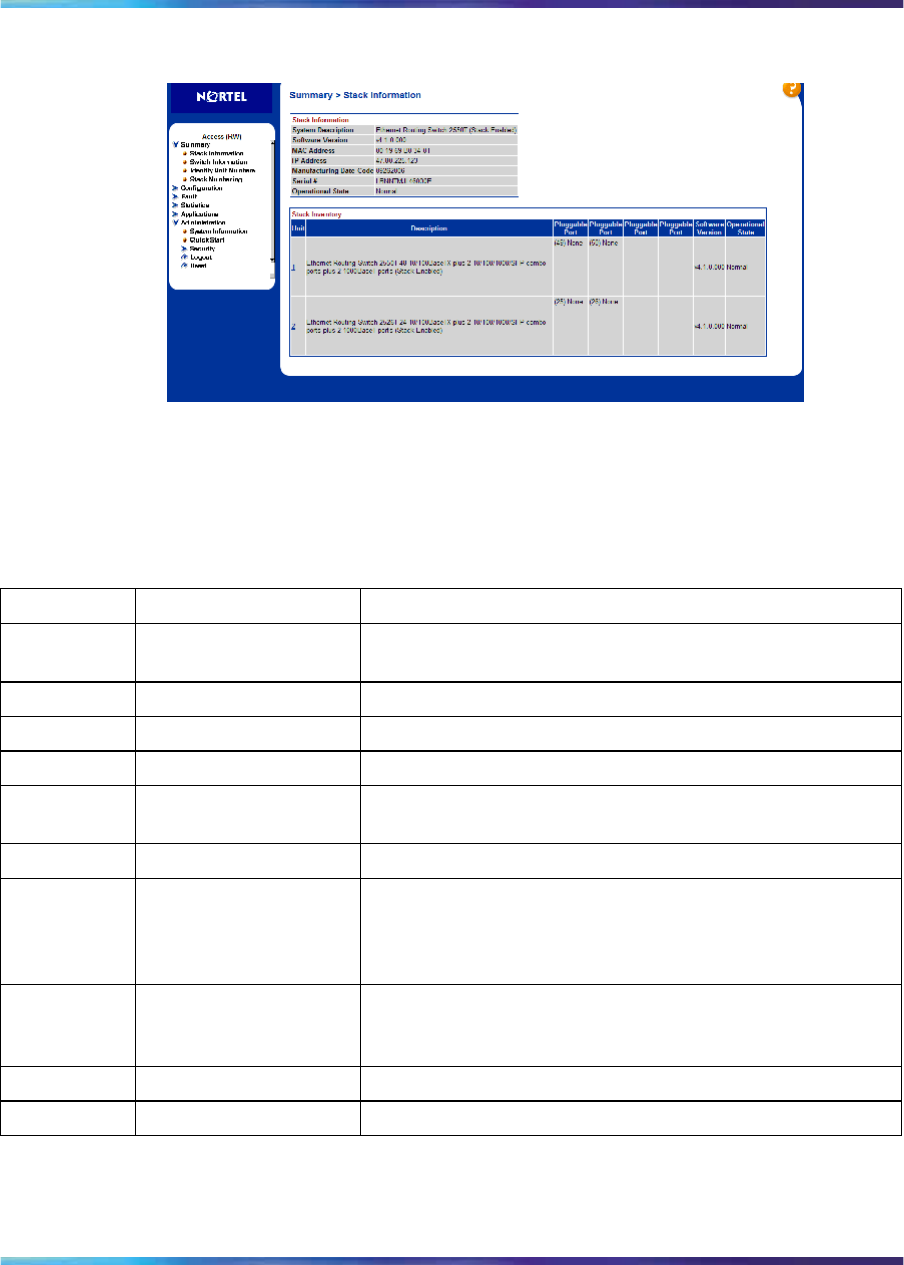
152 Using the Web-based management interface
Figure 49
Stack Information page
"Stack Information screen fields" (page 152) describes the fields on the
Stack Information and Stack Inventory sections of the Stack Information
screen.
Stack Information screen fields
Section Fields Description
Stack Inform
ation System Description The name created in the configuration process to identify
the stack.
Software Version The version of the running software.
MAC Address The MAC address of the stack.
IP Address The IP address of the stack.
Manufacturing Date
Code The date of manufacture of the board in ASCII format:
YYYYMMDD.
Serial Number The serial number of the base unit.
Operational State The current operational state of the device. The operational
states are: Other, Not Available, Removed, Disabled,
Normal, Reset in Progress, Testing, Warning, Non Fatal
Errors, Fatal Error, and Not Configured.
Stack Invent
ory Unit The unit number assigned to the device by the network
manager. For more information about stack numbering,
see "Changing stack numbering" (page 154).
Description The description of the device or its subcomponent.
Pluggable port The SFP GBICs connected to the switch.
Nortel Ethernet Routing Switch 2500 Series
Overview — System Configuration
NN47215-500 (323162-B) 02.02 Standard
4.1 19 November 2007
Copyright © 2007, Nortel Networks
.
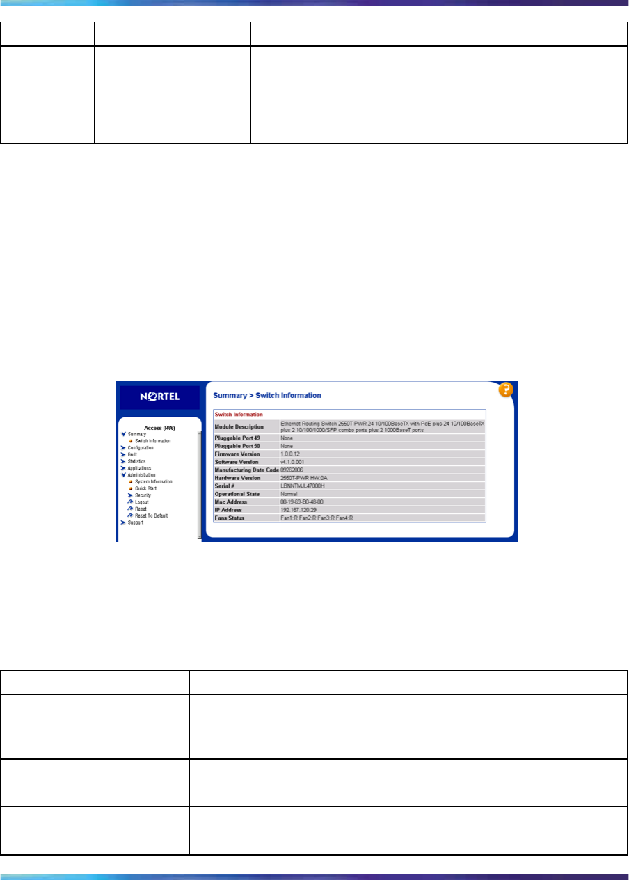
Viewing summary information 153
Section Fields Description
Software Version The current running software version.
Operational State The current operational state of the stack. The operational
states are: Other, Not Available, Removed, Disabled,
Normal, Reset in Progress, Testing, Warning, Non Fatal
Errors, Fatal Error, and Not Configured.
Viewing summary information
You can view summary information about the switch. For example, the unit
number and its corresponding physical description and serial number.
To view summary switch information, use the following procedure:
→From the main menu, choose Summary > Switch Information.
The Switch Information page appears.
Figure 50
Switch Information page
Table 33 "Switch Information page fields" (page 153) describes the fields on
the Switch Information page.
Table 33
Switch Information page fields
Item Description
Module Description The factory set description of the Ethernet Routing Switch 2500
Series.
Pluggable Port 25/49 The factory set description of the sub-component/GBIC.
Pluggable Port 26/50 The factory set description of the sub-component/GBIC.
Firmware Version The firmware version of the Ethernet Routing Switch 2500 Series.
Software Version The version of the running software.
Manufacturing Data Code The date of manufacture of the board in ASCII format.
Nortel Ethernet Routing Switch 2500 Series
Overview — System Configuration
NN47215-500 (323162-B) 02.02 Standard
4.1 19 November 2007
Copyright © 2007, Nortel Networks
.
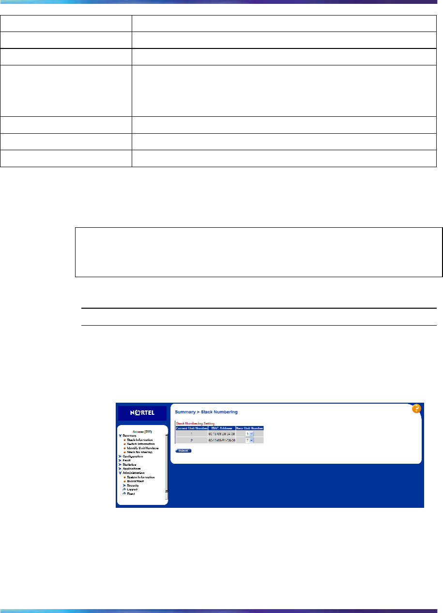
154 Using the Web-based management interface
Item Description
Hardware Version The hardware version of the Ethernet Routing Switch 2500 Series.
Serial # The serial number of the Ethernet Routing Switch 2500 Series.
Operational State The current operational state of the device. The operational states
are: Other, Not Available, Removed, Disabled, Normal, Reset in
Progress, Testing, Warning, Non Fatal Errors, Fatal Error, and Not
Configured.
Mac Address The mac address of the switch.
IP Address The IP address of the switch.
Fans Status The fan status of the switch.
Changing stack numbering
If the system is in a stack, existing stack numbering information can be
viewed and renumbered.
ATTENTION
The unit number does not affect the base unit designation.
To view or renumber devices within the stack framework:
Step Action
1Open the Stack Numbering screen by selecting Summary > Stack
Numbering from the menu. This screen is illustrated in Stack
Numbering page.
Figure 51
Stack Numbering page
"Stack Numbering screen fields" (page 155) describes the fields
on the Stack Numbering screen.
Nortel Ethernet Routing Switch 2500 Series
Overview — System Configuration
NN47215-500 (323162-B) 02.02 Standard
4.1 19 November 2007
Copyright © 2007, Nortel Networks
.

Identifying unit numbers 155
Stack Numbering screen fields
Field Item Range Description
Current Unit
Number 1..8 Unit number previously assigned to the
policy switch. The entries in this column are
displayed in order of their current physical
cabling with respect to the base unit, and
can show non-consecutive unit numbering
if one or more units were previously moved
or modified. The entries also can include
unit numbers of units that are no longer
participating in the stack (not currently
active).
MAC Address XX.XX.XX.XX.XX.X
XMAC address of the corresponding unit
listed in the Current Unit Number field.
Stack Numb
ering Setting
New Unit
Number 1..8, None Choose a new number to assign to your
selected policy switch.
ATTENTION
If you leave the field blank, the system
automatically selects the next available
number.
2Choose the new number to assign to the switch.
3Click Submit.
4A message prompts for confirmation of the request. Click Yes.
—End—
Identifying unit numbers
Identify the unit numbers of the switches participating in a stack configuration
by viewing the LEDs on the front panel of each switch.
To identify unit numbers in your configuration:
Step Action
1Open the Identify Unit Numbers screen by selecting Summary >
Identify Unit Numbers from the menu. This screen is illustrated in
Figure 52 "Identifying Unit Numbers page" (page 156).
Nortel Ethernet Routing Switch 2500 Series
Overview — System Configuration
NN47215-500 (323162-B) 02.02 Standard
4.1 19 November 2007
Copyright © 2007, Nortel Networks
.

156 Using the Web-based management interface
Figure 52
Identifying Unit Numbers page
2To continue viewing summary information or to start the configuration
process, choose another option from the main menu.
—End—
Nortel Ethernet Routing Switch 2500 Series
Overview — System Configuration
NN47215-500 (323162-B) 02.02 Standard
4.1 19 November 2007
Copyright © 2007, Nortel Networks
.

157
Power over Ethernet for the Ethernet
Routing Switch 2526T-PWR and
2550T-PWR
The Ethernet Routing Switch 2550T-PWR and 2526T-PWR provide IEEE
802.3af-compliant power over half of the front-panel RJ-45 ports, located on
the left-hand side of the front panel. The switch provides power discovery,
power management, and statistics on power use on each port and each
switch basis. You can use the Ethernet Routing Switch 2500 Series to
provide power to network appliances, such as IP telephones, wireless
access points, and video devices.
The Ethernet Routing Switch 2526T-PWR and 2550T-PWR provide Power
over Ethernet for 12 and 24 ports with respectively. The switches only
support PoE on the lower-numbered ports (identified by a red border). The
switches provide a maximum of 168 Watts of power to PoE ports. Adequate
power is available to supply, on average, 7 Watts for each port on the
2550T-PWR, and 14 Watts for each port on the 2526T-PWR. A maximum of
15.4 Watts is available on any port for any given device.
The Ethernet Routing Switch 2550T-PWR and 2526T-PWR supply data
terminal equipment (DTE) power only on signal pins.
By default, power is allocated based on real time measurements. If the total
Ethernet power budget for the switch is exceeded, the switch sheds load
by shutting down power to ports.
You configure the Power over Ethernet (PoE) parameters on the PoE ports
using the Command Line Interface (CLI), the web-based management
system, or Device Manager (JDM).
This chapter contains the following topics:
•"Diagnosing and correcting PoE problems" (page 158)
•"Configuring PoE switch parameters using the CLI" (page 158)
•"Configuring PoE port parameters using the CLI" (page 160)
•"Displaying PoE configuration using the CLI" (page 164)
•"Configuring PoE using Web-based management" (page 167)
Nortel Ethernet Routing Switch 2500 Series
Overview — System Configuration
NN47215-500 (323162-B) 02.02 Standard
4.1 19 November 2007
Copyright © 2007, Nortel Networks
.

158 Power over Ethernet for the Ethernet Routing Switch 2526T-PWR and 2550T-PWR
•"Editing and viewing switch PoE configurations using Device Manager"
(page 172)
Diagnosing and correcting PoE problems
This section discusses some common problems in using the PoE features
of the Ethernet Routing Switch 2500-PWR. This section discusses the
following topics:
•"Status codes on PoE ports" (page 158)
Status codes on PoE ports
You may see an error displayed for a port running PoE. If these errors
appear, they are in the port status section of the PoE displays in the CLI
and the web-based management system. The following are the messages
that display and their explanations:
•Detecting—port detecting IP device requesting power
•Delivering power—port delivering requested power to device
•Disabled—port power state disabled
•Invalid PD—port detecting device that is not valid to request power
•Deny low priority—power disabled from port because of port setting and
demands on power budget
•Overload—power disabled from port because port is overloaded
•Test—port in testing mode, which is set using SNMP
•Error—an unspecified error condition
Configuring PoE switch parameters using the CLI
You configure power parameters for each Ethernet Routing Switch
2500-PWR using the CLI. You can configure the DC power source, the
power pairs, and the power usage with this management system. This
section contains information about the following topics:
•"poe poe-pd-detect-type command" (page 158)
•"poe poe-power-usage-threshold command" (page 159)
•"poe poe-trap command" (page 160)
•"no poe-trap command" (page 160)
poe poe-pd-detect-type command
The poe poe-pd-detect-type command sets the method the Ethernet
Routing Switch 2500-PWR uses to detect the power devices connected to
the front ports. The syntax for the poe poe-pd-detect-type command
is:
Nortel Ethernet Routing Switch 2500 Series
Overview — System Configuration
NN47215-500 (323162-B) 02.02 Standard
4.1 19 November 2007
Copyright © 2007, Nortel Networks
.

Configuring PoE switch parameters using the CLI 159
poe poe-pd-detect-type
{802dot3af | 802dot3af_and_legacy | Unit}
The poe poe-pd-detect-type command is executed in the Global
Configuration command mode.
ATTENTION
You must ensure that this setting is the correct one for the IP appliance you
use with the switch. Please note this setting applies to the entire switch, not
port-by-port. So, you must ensure that this setting is configured correctly for all
the IP appliances on a specified switch.
describes the parameters and variables for the poe poe-pd-detect-type
command.
Table 34
poe poe-pd-detect-type command parameters and variables
Parameters and
variables Description
802dot3af |
802dot3af_and
_legacy
Sets the detection method the switch use to detect power needs of devices
connected to front ports:
• 802dot3af
• 802dot3af_and_legacy
ATTENTION
The default setting is 802dot3af. Ensure that the power detection method
you choose for the Ethernet Routing Switch 2500-PWR matches that used
by the IP devices you are powering.
Unit Set the unit in stack to apply the detection method.
poe poe-power-usage-threshold command
The poe poe-power-usage-threshold command lets you set a
percentage usage threshold above which the system sends a trap
for each Ethernet Routing Switch 2500-PWR. The syntax for the poe
poe-power-usage-threshold command is:
poe poe-power-usage-threshold {<1-99> | Unit}
The poe poe-power-usage-threshold command is executed in the
Global Configuration command mode.
Nortel Ethernet Routing Switch 2500 Series
Overview — System Configuration
NN47215-500 (323162-B) 02.02 Standard
4.1 19 November 2007
Copyright © 2007, Nortel Networks
.

160 Power over Ethernet for the Ethernet Routing Switch 2526T-PWR and 2550T-PWR
Table 35 "poe poe-power-usage-threshold command parameters and
variables" (page 160) describes the parameters and variables for the poe
poe-power-usage-threshold command.
Table 35
poe poe-power-usage-threshold command parameters and variables
Parameters and
variables Description
<1-99> Enter the percentage of total available power you
want the switch to use prior to sending a trap.
ATTENTION
The default setting is 80%.
Unit Set a percentage usage threshold above which the
system sends a trap for each unit.
poe poe-trap command
The poe poe-trap command enables the traps for the PoE functions on
the Ethernet Routing Switch 2500-PWR. The syntax for the poe poe-trap
command is:
poe poe-trap {Unit}
The poe poe-trap command is executed in the Global Configuration
command mode.
no poe-trap command
The no poe-trap command disables the traps for the PoE functions on
the Ethernet Routing Switch 2500-PWR. The syntax for the no poe-trap
command is:
no poe-trap {Unit}
The no poe-trap command is executed in the Global Configuration
command mode.
Configuring PoE port parameters using the CLI
You can configure power parameters for each port on the Ethernet Routing
Switch 2500 PWR Series using the CLI. You enable the power and set
the power limit and power priority on each port. This section covers the
following topics:
•"no poe-shutdown command" (page 161)
Nortel Ethernet Routing Switch 2500 Series
Overview — System Configuration
NN47215-500 (323162-B) 02.02 Standard
4.1 19 November 2007
Copyright © 2007, Nortel Networks
.

Configuring PoE port parameters using the CLI 161
•"poe poe-shutdown command" (page 161)
•"poe poe-priority command" (page 162)
•"poe poe-limit command" (page 163)
no poe-shutdown command
The no poe-shutdown command enables power to the port. The syntax
for the no poe-shutdown command is:
no poe-shutdown [port <portlist>]
The no poe-shutdown command is executed in the Interface
Configuration command mode.
Table 36 "no poe-shutdown command parameters and variables" (page
161) describes the parameters and variables for the no poe-shutdown
command.
Table 36
no poe-shutdown command parameters and variables
Parameters and
variables Description
port <portlist> Enter the port numbers on which you want to enable
power.
The default value is enabled.
ATTENTION
If you omit this parameter, the system uses the
port entered with the interface FastEthernet
command.
poe poe-shutdown command
The poe poe-shutdown command disables power to the port. The syntax
for the poe poe-shutdown command is:
poe poe-shutdown [port <portlist>]
The poe poe-shutdown command is executed in the Interface
Configuration command mode.
Nortel Ethernet Routing Switch 2500 Series
Overview — System Configuration
NN47215-500 (323162-B) 02.02 Standard
4.1 19 November 2007
Copyright © 2007, Nortel Networks
.

162 Power over Ethernet for the Ethernet Routing Switch 2526T-PWR and 2550T-PWR
Table 37 "poe poe-shutdown command parameters and variables" (page
162) describes the parameters and variables for the poe poe-shutdown
command.
Table 37
poe poe-shutdown command parameters and variables
Parameters and
variables Description
port <portlist> Enter the port numbers on which you want to disable
power.
The default value is enabled.
ATTENTION
If you omit this parameter, the system uses the
port entered with the interface FastEthernet
command.
poe poe-priority command
The poe poe-priority command lets you set the power priority for each
port to low, high, or critical. The system uses the port power priority settings
to distribute power to the ports depending on the available power budget.
The syntax for the poe poe-priority command is:
poe poe-priority [port <portlist>] {low | high | critical}
The poe poe-priority command is executed in the Interface
Configuration command mode.
Table 38 "poe poe-priority command parameters and variables" (page
162) describes the parameters and variables for the poe poe-priority
command.
Table 38
poe poe-priority command parameters and variables
Parameters and
variables Description
port <portlist> Enter the port numbers on which you want to disable
power.
Nortel Ethernet Routing Switch 2500 Series
Overview — System Configuration
NN47215-500 (323162-B) 02.02 Standard
4.1 19 November 2007
Copyright © 2007, Nortel Networks
.

Configuring PoE port parameters using the CLI 163
Parameters and
variables Description
ATTENTION
If you omit this parameter, the system uses the
port entered with the interface FastEthernet
command.
low | high |
critical Sets the port priority as:
•
low
•
high
•
critical
ATTENTION
The default setting is low. When two ports have the
same priority and one must be shut down, the port
with the higher port number is shut down first.
poe poe-limit command
The poe poe-limit command sets the maximum power allowed to a
port. The syntax for the poe poe-limit command is:
poe poe-limit [port <portlist>] <3-16>
The poe poe-limit command is executed in the Interface Configuration
command mode.
Table 39 "poe poe-limit command parameters and variables" (page
164) describes the parameters and variables for the poe poe-limit command.
Nortel Ethernet Routing Switch 2500 Series
Overview — System Configuration
NN47215-500 (323162-B) 02.02 Standard
4.1 19 November 2007
Copyright © 2007, Nortel Networks
.

164 Power over Ethernet for the Ethernet Routing Switch 2526T-PWR and 2550T-PWR
Table 39
poe poe-limit command parameters and variables
Parameters and
variables Description
<3-16> Enter the maximum number of watts you want for the
specified port.
The range is 3W to 16W; the default value is 16W.
ports Enter the port number you want to disable power on.
ATTENTION
If you omit this parameter, the system uses the
port entered with the interface FastEthernet
command.
Displaying PoE configuration using the CLI
You display the status for the PoE configuration on the Ethernet Routing
Switch 2500-PWR using the following CLI commands:
•"show poe-main-status command" (page 164)
•"show poe-port-status command" (page 165)
•"show poe-power-measurement command" (page 166)
show poe-main-status command
The show poe-main-status command displays the current PoE
configuration of the Ethernet Routing Switch 2500-PWR, and each port PoE
settings. The syntax for the show poe-main-status command is:
show poe-main-status {Unit}
The show poe-main-status command is executed in the User Exec
command mode.
Figure 53 "show poe-main-status" (page 165) displays sample output from
the show poe-main-status command.
Nortel Ethernet Routing Switch 2500 Series
Overview — System Configuration
NN47215-500 (323162-B) 02.02 Standard
4.1 19 November 2007
Copyright © 2007, Nortel Networks
.
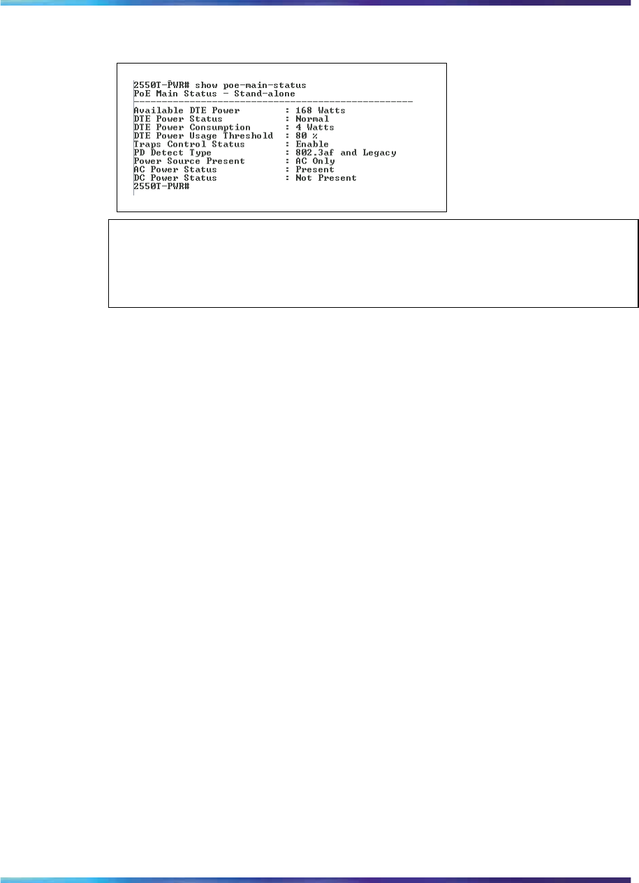
Displaying PoE configuration using the CLI 165
Figure 53
show poe-main-status command output
ATTENTION
The Power Source Present listing displays the current power source for the
switch: AC Only.
show poe-port-status command
The show poe-port-status command displays the status, power
status, power limit, and port priority of each port. The syntax for the show
poe-port-status command is:
show poe-port-status [port <portlist>]
The show poe-port-status command is executed in the User Exec
command mode.
The DTE Power Status displays error messages if the port is not providing
power. The following messages can appear:
•Detecting—port detecting IP device requesting power
•Delivering power—port delivering requested power to device
•Invalid PD—port detecting device that is not valid to request power
•Deny low priority—power disabled from port because of port setting and
demands on power budget
•Overload—power disabled from port because port is overloaded
•Test—port in testing mode
•Error—none of the other conditions apply
Table 40 "show poe-port-status command parameters and variables" (page
166) describes the parameters and variables for the show poe-port-status
command.
Nortel Ethernet Routing Switch 2500 Series
Overview — System Configuration
NN47215-500 (323162-B) 02.02 Standard
4.1 19 November 2007
Copyright © 2007, Nortel Networks
.
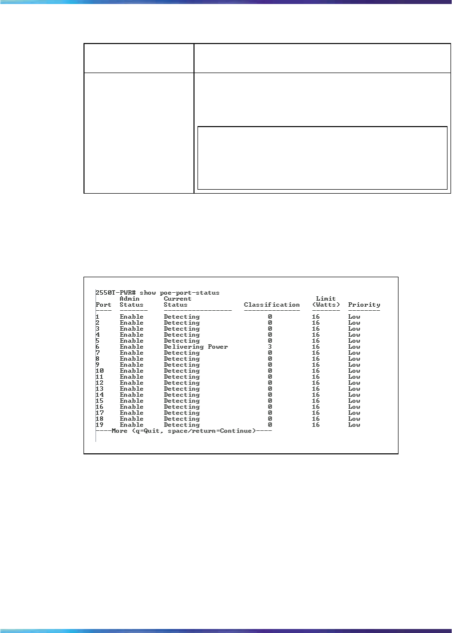
166 Power over Ethernet for the Ethernet Routing Switch 2526T-PWR and 2550T-PWR
Table 40
show poe-port-status command parameters and variables
Parameters and
variables Description
port <portlist> Enter the ports for which you want to display the
status.
ATTENTION
If you omit this parameter, the system displays all
ports.
Figure 54 "show poe-port-status command output" (page 166) displays
sample output from the show poe-port-status command.
Figure 54
show poe-port-status command output
show poe-power-measurement command
The show poe-power-measurement command displays the voltage,
current and power values for each powered device connected to each port.
The syntax for the show poe-power-measurement command is:
show poe-power-measurement [port <portlist>]
The show poe-power-measurement command is executed in the User
Exec command mode.
Nortel Ethernet Routing Switch 2500 Series
Overview — System Configuration
NN47215-500 (323162-B) 02.02 Standard
4.1 19 November 2007
Copyright © 2007, Nortel Networks
.
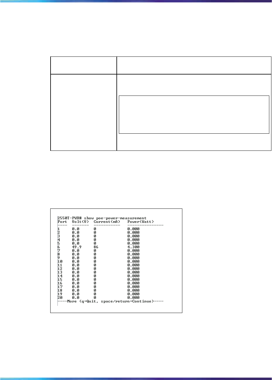
Configuring PoE using web-based management 167
Table 41 "show poe-power-measurement command parameters and
variables" (page 167) shows the variables and parameters for the show
poe-power-measurement command.
Table 41
show poe-power-measurement command parameters and variables
Parameters and
variables Description
port
<portlist> Enter the ports for which you want to display the
power measurements.
ATTENTION
If you omit this parameter, the system displays all
ports.
Figure 55 " show poe-power-measurement command output" (page
167) displays sample output from the show poe-power-measurement
command.
Figure 55
show poe-power-measurement command output
Configuring PoE using web-based management
You can display and configure Power over Ethernet (PoE) parameters using
the web-based management system.
•"Displaying and configuring power management for the switch" (page
168)
Nortel Ethernet Routing Switch 2500 Series
Overview — System Configuration
NN47215-500 (323162-B) 02.02 Standard
4.1 19 November 2007
Copyright © 2007, Nortel Networks
.
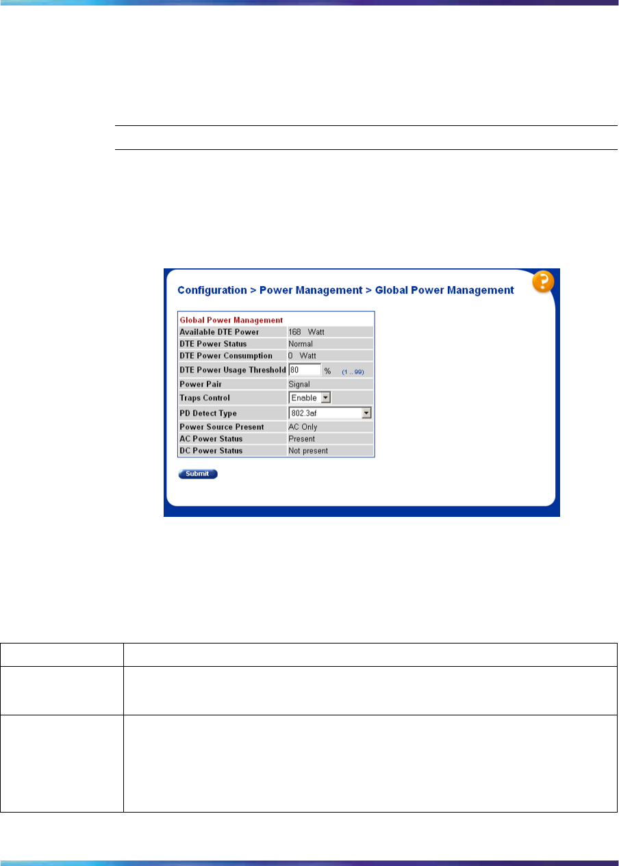
168 Power over Ethernet for the Ethernet Routing Switch 2526T-PWR and 2550T-PWR
•"Displaying and configuring power management for the ports" (page 170)
Displaying and configuring power management for the switch
To display and configure power settings for the entire switch, use the
following procedure:
Step Action
1From the main menu, choose Configuration > PoE Management
> Global Power Mgmt.
The Global Power Management page appears ("Global Power
Management page" (page 168)).
Global Power Management page
The following table describes the items on the Global Power
Management page.
Table 42
Global Power Management page items
Item Description
Available DTE
Power Displays the amount of power available to powered devices from the switch.
DTE Power Status Displays the status of the PoE feature. It displays:
•Normal--all power functioning correctly
•Error--PoE failed
Nortel Ethernet Routing Switch 2500 Series
Overview — System Configuration
NN47215-500 (323162-B) 02.02 Standard
4.1 19 November 2007
Copyright © 2007, Nortel Networks
.

Configuring PoE using web-based management 169
Item Description
DTE Power
Consumption Displays total power use on all devices currently drawing power.
DTE Power
Usage Threshold Enter the percentage of total power consumption on the switch necessary to
trigger a trap.
The default value is 80%.
Power Pair Displays the power pair of the RJ-45 pin connectors that supplies the power.
The only available option for the Ethernet Routing Switch 2500 Seris is Signal.
ATTENTION
Ensure that the power pair used by the IP devices you are powering
matches the power pair for the Ethernet Routing Switch 2500 Series.
Traps Control Choose to enable or disable trap from agent.
PD Detect Type Choose the type of power detection you want for the switch:
•802.3af
•802.3af and legacy
The default is 802.3af.
ATTENTION
Ensure that the power detection method you choose for the Ethernet
Routing Switch 2500 Series matches that used by the IP devices you are
powering.
Power Source
Present This display-only field displays the current power supply for the switch:
•AC Only--using only the internal power source of the switch
AC Power Status Displays the current status of AC power on the switch.
DC Power Status Displays the current status of DC power on the switch (Not Present).
2Type the information, or make a selection from the list.
3Click Submit.
—End—
Nortel Ethernet Routing Switch 2500 Series
Overview — System Configuration
NN47215-500 (323162-B) 02.02 Standard
4.1 19 November 2007
Copyright © 2007, Nortel Networks
.
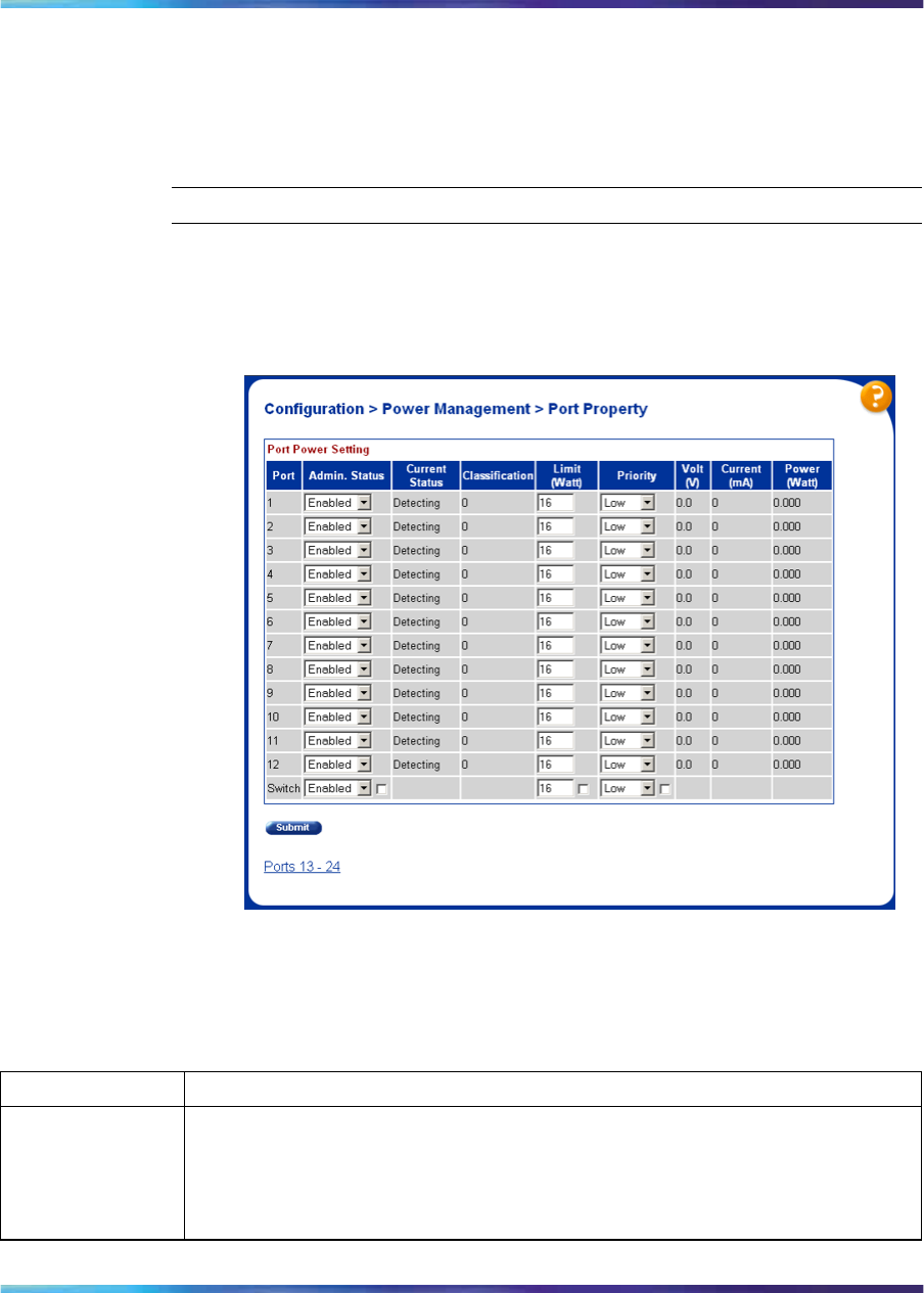
170 Power over Ethernet for the Ethernet Routing Switch 2526T-PWR and 2550T-PWR
Displaying and configuring power management for the ports
To configure power management settings for each port, use the following
procedure:
Step Action
1From the main menu, choose Configuration > PoE Management >
Port Property.
The Port Property page appears ("Port Property page" (page 170)).
Port Property page
The following table describes the items on the Port Property page.
Table 43
Port Property page items
Item Description
Admin Status Choose to enable or disable power on the selected port.
The default value is Enabled.
Nortel Ethernet Routing Switch 2500 Series
Overview — System Configuration
NN47215-500 (323162-B) 02.02 Standard
4.1 19 November 2007
Copyright © 2007, Nortel Networks
.

Configuring PoE using web-based management 171
Item Description
Current Status Displays the status of the PoE feature. It displays:
•Disabled—detecting function is disabled
•Searching—detecting function is enabled and the system is searching for
a valid powered device on this port
•Delivering power— detection found a valid powered device and the port
is delivering power
•Fault—power-specific fault detected on the port
•Test—detecting function is in test mode, which is set using SNMP
•Other fault—detecting function is idle due to fault
ATTENTION
Nortel recommends against using the test operational status.
Classifica-
tion Classification is a way to tag different terminals on the power over LAN network
according to their power consumption. Devices such as IP telephones, WLAN
access points, and others are classified according to their power requirements.
The meaning of the classification labels is defined in the IEEE 802.3af
specification.
This parameter is valid only while a device is being powered.
Limit (Watt) Sets the maximum amount of power supplied to that port.
The range for Ethernet Routing Switch 2500 Series is 3W to 16W. The default
value is 16W.
Priority Priority is used to determine which port(s) are shut down when the total power
of the Ethernet Routing Switch 2500 Series exceeds the power budget for
that switch (or available DTE power). The lower priority ports are shut down
in favor of higher priority ports.
The range is low, high, and critical. The default value is low.
ATTENTION
When two ports have the same priority and one must be shut down, the port
with the higher port number is shut down first.
Volt (V) Displays the measured voltage supplied by the port.
Current (mA) Displays the measured current supplied by the port.
Power (Watt) Displays the measured power supplied by the port.
Nortel Ethernet Routing Switch 2500 Series
Overview — System Configuration
NN47215-500 (323162-B) 02.02 Standard
4.1 19 November 2007
Copyright © 2007, Nortel Networks
.

172 Power over Ethernet for the Ethernet Routing Switch 2526T-PWR and 2550T-PWR
2Type the information, or make a selection from the list.
3Click Submit.
—End—
Editing and viewing switch PoE configurations using Device
Manager You can use Device Manager to view and edit the Power over Ethernet
(PoE) parameters that apply to the whole switch. You can also use Device
Manager to set PoE parameters on individual ports.
One PoE-related tab that is not described in this section is the Power Supply
tab. This tab is accessible through the Chassis dialog box, and it displays
the status of the internal power supply (see Power Supply tab ).
The following sections provide a description of the PoE tabs, and details
about each item on the tab:
•"PoE tab for a single unit" (page 172)
•"Device Manager display for PoE ports" (page 174)
•"PoE tab for ports" (page 175)
PoE tab for a single unit
To open the PoE tab for a single unit, use the following procedure:
Step Action
1Select a single unit.
2From the shortcut menu, choose Edit > Unit.
The Unit dialog box appears with the Unit tab displayed .
3Click the PoE tab.
The PoE tab appears.
Nortel Ethernet Routing Switch 2500 Series
Overview — System Configuration
NN47215-500 (323162-B) 02.02 Standard
4.1 19 November 2007
Copyright © 2007, Nortel Networks
.
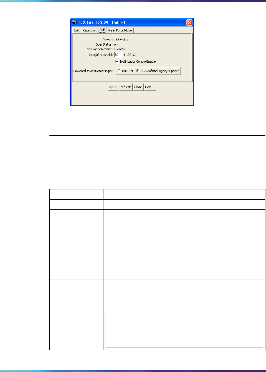
Editing and viewing switch PoE configurations using Device Manager 173
Edit Unit dialog box—PoE tab for a single unit
—End—
Table 44 "PoE tab items for a single unit" (page 173) describes the PoE
tab items for a single unit.
Table 44
PoE tab items for a single unit
Item Description
Power Displays the total power available to the switch.
OperStatus Displays the power state of the switch:
•on
•off
•faulty
Consumption
Power Displays the power being used by the switch.
UsageThreshold Lets you set a percentage of the total power usage of the
switch above which the system sends a trap.
ATTENTION
You must enable the traps (NotificationControlEnable)
to receive a power usage trap.
Nortel Ethernet Routing Switch 2500 Series
Overview — System Configuration
NN47215-500 (323162-B) 02.02 Standard
4.1 19 November 2007
Copyright © 2007, Nortel Networks
.
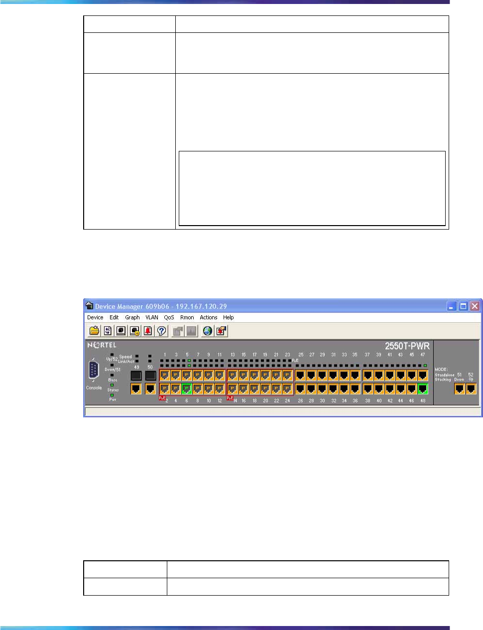
174 Power over Ethernet for the Ethernet Routing Switch 2526T-PWR and 2550T-PWR
Item Description
Notification
ControlEnable Lets you enable or disable sending traps if the switch power
usage exceeds the percentage set in the UsageThreshold
field.
PowerDevice
DetectType Lets you set the power detection type that the switch uses
to detect a request for power from a device connected to
all ports on the switch:
• 802.3af
• 802.3af and legacy
ATTENTION
The default setting is 802.3af. Ensure that this setting
matches the setting for the detection type used by the
powered devices on this switch.
Device Manager display for PoE ports
The Device Manager displays PoE ports differently than non-PoE port.
ERS 2550T-PWR with PoE ports
The port coloring scheme for the data aspect is the same for PoE ports
as for all other ports. The difference for the PoE ports is the addition of
the power aspect (colored p).
Table 45 "Port power color codes" (page 174) shows the status assigned to
each color.
Table 45
Port power color codes
Color Description
Green P Specifies that the port is currently delivering power.
Nortel Ethernet Routing Switch 2500 Series
Overview — System Configuration
NN47215-500 (323162-B) 02.02 Standard
4.1 19 November 2007
Copyright © 2007, Nortel Networks
.
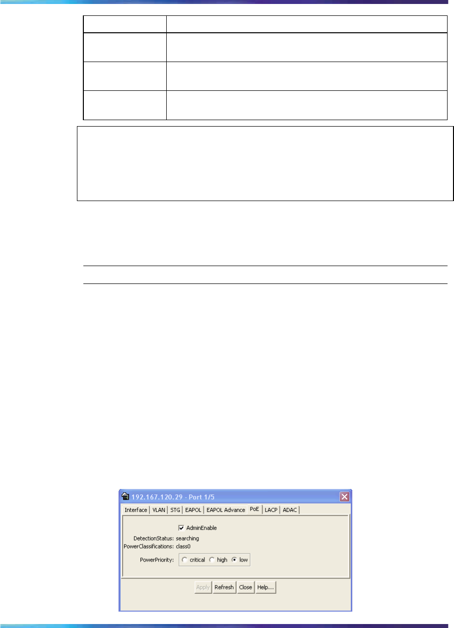
Editing and viewing switch PoE configurations using Device Manager 175
Color Description
Red P Specifies that the power and detection mechanism for the
port is disabled.
Orange P Specifies that the power and detection mechanism for the port
is enabled. However the port is not currently delivering power.
White/Gray P Specifies that the power and detection mechanism for the
port is unknown.
ATTENTION
The coloring scheme for data aspect and the power aspect are independent of
each other. With this GUI enhancement, you can view the initial status for both
data and power aspect for the port.
PoE tab for ports
The PoE tab lets you configure PoE power settings for ports.
To view the PoE tab, use the following procedure:
Step Action
1Select the port you want to edit.
2Do one of the following:
•Double-click the selected port.
•From the shortcut menu, choose Edit.
•From the Device Manager main menu, choose Edit > Port.
•On the toolbar, click Edit.
The Port dialog box appears with the Interface tab displayed.
3Click the PoE tab.
The PoE tab appears.
Edit Port dialog box— PoE tab
Nortel Ethernet Routing Switch 2500 Series
Overview — System Configuration
NN47215-500 (323162-B) 02.02 Standard
4.1 19 November 2007
Copyright © 2007, Nortel Networks
.

176 Power over Ethernet for the Ethernet Routing Switch 2526T-PWR and 2550T-PWR
—End—
PoE tab items
Table 46 "PoE tab items" (page 176) describes the PoE tab items.
Table 46
PoE tab items
Item Description
AdminEnable Lets you enable or disable PoE on this port.
By default, PoE is enabled.
Detection Status Displays the operational status of the power-device
detecting mode on the specified port:
• disabled—detecting function disabled
• searching—detecting function is enabled and the
system is searching for a valid powered device on
this port
• deliveringPower—detection found a valid powered
device and the port is delivering power
• fault—power-specific fault detected on port
• test—detecting device in test mode
• otherFault
ATTENTION
Nortel recommends against using the test
operational status.
PowerClassifications Classification is a way to tag different terminals on
the Power over LAN network according to their power
consumption. Devices such as IP telephones, WLAN
access points, and others can be classified according to
their power requirements.
PowerPriority Lets you set the power priority for the specified port to:
•critical
•high
•low
Nortel Ethernet Routing Switch 2500 Series
Overview — System Configuration
NN47215-500 (323162-B) 02.02 Standard
4.1 19 November 2007
Copyright © 2007, Nortel Networks
.

177
System configuration using the CLI
In the Ethernet Routing Switch 2500 Series, the Command Line Interface
(CLI) commands lets you display and modify the switch configuration while
the switch is operating.
This chapter includes information about general switch maintenance, such
as setting up access parameters, upgrading the software, and setting the
speed. This chapter contains information about the following topics:
•"Configuring the switch IP address, subnet mask and default gateway"
(page 177)
•"Using DNS to ping and telnet" (page 184)
•"Configuration Management" (page 188)
•"Customizing your system" (page 193)
•"Displaying the ARP table" (page 202)
•"Displaying interfaces" (page 202)
•"Saving the configuration to NVRAM" (page 205)
•"Enabling and disabling autosave" (page 206)
•"Setting time on network elements using Simple Network Time Protocol"
(page 208)
•"Enabling Autopology" (page 215)
•"Configuring LLDP using the CLI" (page 217)
•"Configuring LEDs to blink on the display panel" (page 229)
•"Upgrading software" (page 229)
Configuring the switch IP address, subnet mask and default gateway
IP notation
To enter IP addresses and subnet masks in the CLI, enter both
the IP address and the subnet mask in dotted decimal notation
(XXX.XXX.XXX.XXX).
Nortel Ethernet Routing Switch 2500 Series
Overview — System Configuration
NN47215-500 (323162-B) 02.02 Standard
4.1 19 November 2007
Copyright © 2007, Nortel Networks
.

178 System configuration using the CLI
Assigning and clearing IP addresses
Using the CLI, you can assign IP addresses and Gateway addresses, clear
these addresses, and view configured IP addresses. This section contains
information about the following topics:
•"ip address command" (page 178)
•"default ip address command" (page 179)
•"no ip address command" (page 179)
•"default ip netmask command" (page 179)
•"no ip netmask command" (page 179)
•"ip default-gateway command" (page 180)
•"no ip default-gateway command" (page 180)
•"default ip default-gateway command" (page 181)
•"show ip command" (page 181)
ip address command
The ip address command sets the IP address and subnet mask for the
switch. The syntax for the ip address command is:
ip address <XXX.XXX.XXX.XXX> [netmask <XXX.XXX.XXX.XXX>]
The ip address command is executed in the Global Configuration
command mode.
Table 47 "ip address command parameters and variables" (page
178) describes the parameters and variables for the ip address command.
Table 47
ip address command parameters and variables
Parameters and
variables Description
XXX.XXX.XXX.XXX Enter IP address in dotted decimal notation; netmask is
optional.
netmask Set the IP subnet mask for the switch.
ATTENTION
When you change the IP address or subnet mask, you may lose connection
to Telnet and the Web.
Nortel Ethernet Routing Switch 2500 Series
Overview — System Configuration
NN47215-500 (323162-B) 02.02 Standard
4.1 19 November 2007
Copyright © 2007, Nortel Networks
.

Configuring the switch IP address, subnet mask and default gateway 179
default ip address command
The default ip address command sets the IP address for the
specified unit to the default value as 192.168.1.1 for Standalone Mode and
192.168.1.2 for Stacking Mode. The syntax for the default ip address
command is:
default ip address
The default ip address command is executed in the Global
Configuration command mode.
no ip address command
The no ip address command clears the IP address and subnet mask.
This command sets the IP address and subnet mask for a switch to all zeros
(0). The syntax for the no ip address command is:
no ip address
The no ip address command is executed in the Global Configuration
command mode.
The no ip address command has no parameters or variables.
ATTENTION
When you change the IP address or subnet mask, you may lose connection to
Telnet and the Web. You also disable any new Telnet connection, and you must
connect to the serial Console port to configure a new IP address.
default ip netmask command
The default ip netmask command sets the subnet mask to the
default value (255.255.255.0). The syntax for the default ip netmask
command is:
default ip netmask
The default ip netmask command is executed in the Global
Configuration command mode.
The default ip netmask command has no parameters or variables .
no ip netmask command
The no ip netmask command sets the subnet mask for a switch to all
zeros (000.000.000.000). The syntax for the no ip netmask command
is:
no ip netmask
Nortel Ethernet Routing Switch 2500 Series
Overview — System Configuration
NN47215-500 (323162-B) 02.02 Standard
4.1 19 November 2007
Copyright © 2007, Nortel Networks
.

180 System configuration using the CLI
The no ip netmask command is executed in the Global Configuration
command mode.
The no ip netmask command has no parameters or variables .
ip default-gateway command
The ip default-gateway command sets the IP default gateway address
for a switch. The syntax for the ip default-gateway command is:
ip default-gateway <XXX.XXX.XXX.XXX>
The ip default-gateway command is executed in the Global
Configuration command mode.
Table 48 "ip default-gateway command parameters and variables" (page
180) describes the parameters and variables for the ip default-gateway
command.
Table 48
ip default-gateway command parameters and variables
Parameters and
variables Description
XXX.XXX.XXX.XXX Enter the dotted-decimal IP address of the default IP
gateway.
ATTENTION
When you change the IP gateway, you may lose connection to Telnet and the Web.
no ip default-gateway command
The no ip default-gateway command sets the IP default gateway
address to zeros (0). The syntax for the no ip default-gateway
command is:
no ip default-gateway
The no ip default-gateway command is executed in the Global
Configuration command mode.
The no ip default-gateway command has no parameters or variables.
ATTENTION
When you change the IP gateway address, you may lose connection to Telnet and
the Web. You also may disable any new Telnet connection required to connect to
the serial Console port to configure a new IP Gateway address.
Nortel Ethernet Routing Switch 2500 Series
Overview — System Configuration
NN47215-500 (323162-B) 02.02 Standard
4.1 19 November 2007
Copyright © 2007, Nortel Networks
.

Configuring the switch IP address, subnet mask and default gateway 181
default ip default-gateway command
The default ip default-gateway command sets the IP default
gateway address to all zeros (000.000.000.000). The syntax for the
default ip default-gateway command is:
default ip default-gateway
The default ip default-gateway command is executed in the Global
Configuration command mode.
The default ip default-gateway command has no parameters or
variables.
show ip command
The show ip command displays the IP configurations, specifically BootP
mode, switch address, subnet mask, and gateway address. This command
displays the these parameters for what is configured, what is in use, and the
last BootP. The syntax for the show ip command is:
show ip [bootp] [default-gateway] [address [switch]] [dns]
The show ip command is executed in the User Exec command mode.
If you do not enter any parameters, this command displays all the IP-related
configuration information.
Table 49 "show ip command parameters and variables" (page 181) describes
the parameters and variables for the show ip command.
Table 49
show ip command parameters and variables
Parameters and
variables Description
bootp mode Displays BootP-related IP information.
default-gateway Displays the IP address of the default gateway.
address Displays the current IP address.
switch Specifies current IP address of the switch.
dns Displays DNS configuration.
Figure 56 "show ip command output" (page 182) displays a sample output
of the show ip command.
Nortel Ethernet Routing Switch 2500 Series
Overview — System Configuration
NN47215-500 (323162-B) 02.02 Standard
4.1 19 November 2007
Copyright © 2007, Nortel Networks
.
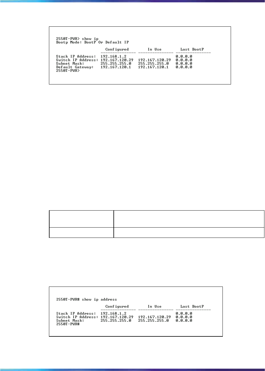
182 System configuration using the CLI
Figure 56
show ip command output
show ip address command
The show ip address command displays the IP configurations, switch
address, subnet mask, and gateway address. The syntax for the show
ip address command is:
show ip address
The show ip address command is executed in the User Exec command
mode.
Table 50 "show ip address command parameters and variables" (page
182) describes the parameters and variables for the show ip address
command.
Table 50
show ip address command parameters and variables
Parameters and
variables Description
address Displays the current IP address.
Figure 57 "show ip address command output" (page 182) displays a sample
output of the show ip address command.
Figure 57
show ip address command output
Nortel Ethernet Routing Switch 2500 Series
Overview — System Configuration
NN47215-500 (323162-B) 02.02 Standard
4.1 19 November 2007
Copyright © 2007, Nortel Networks
.

Configuring the switch IP address, subnet mask and default gateway 183
Pinging
To ensure that the Ethernet Routing Switch 2500 Series has connectivity to
the network, ping a device you know is connected to this network.
ping command
The ping command tests the network connection to another network
device. The command sends an Internet Control Message Protocol (ICMP)
packet from the switch to the target device. The local IP address must be
set before issuing the ping command. See "Assigning and clearing IP
addresses" (page 178) for information on setting IP addresses.
The syntax for the ping command is:
ping <XXX.XXX.XXX.XXX> [datasize <64-4096>]
[{count <1-9999>} | continuous] [{timeout | -t} <1-120>]
[interval <1-60>] [debug]
The ping command is executed in the User Exec command mode.
Table 51 "ping command parameters and variables" (page 183) describes
the parameters and variables for the ping command.
Table 51
ping command parameters and variables
Parameters and
variables Description
XXX.XXX.XXX.XXX Specify the IP address of the target device in
dotted-decimal notation.
datasize
<64-4096>
Specifies the size of the ICMP packet to be sent. The
data size range is from 64 to 4096 bytes.
{count <1-9999> }
| continuous
Sets the number of ICMP packets to be sent. The
continuous mode sets the ping running until the user
interrupts it by entering Ctrl-C.
{timeout | -t}
<1-120>
Set the timeout using either the timeout or -t
parameter followed by the number of seconds the switch
must wait before timing out.
interval <1-60> Specifies the number of seconds between transmitted
packets.
debug Provides additional output information such as ICMP
sequence number and trip time.
If the device receives the packet, it sends a ping reply. When the switch
receives the reply, it displays a message indicating that the specified IP
address is being used. If no reply is received, a message indicates that the
address is not responding.
Nortel Ethernet Routing Switch 2500 Series
Overview — System Configuration
NN47215-500 (323162-B) 02.02 Standard
4.1 19 November 2007
Copyright © 2007, Nortel Networks
.

184 System configuration using the CLI
Figure 58 "ping command responses" (page 184) shows sample ping
responses.
Figure 58
ping command responses
Resetting the switch to default configuration
The restore factory-default command resets the switch to its
default configuration.
The syntax for the restore factory-default command is:
restore factory-default [ -y | force]
where the -y or force parameter instructs the switch not to prompt for
confirmation. If the -y or force parameter is not included in the command,
the following message appears:
Warning the switch will be reset to factory default
configuration
Do you wish to continue (y/n) ?
Enter yto restore the switch to default.
The restore factory-default command is executed in the Privileged
EXEC command mode.
Using DNS to ping and telnet
Using the Domain Name Server (DNS) client, you can ping or telnet to a
host server or to a host by name. To use this feature, you must configure
at least one DNS; you may also configure a default domain name. If you
configure a default domain name, that name is appended to hostnames that
do not contain a dot. The default domain name and addresses are saved
in NVRAM.
The hostnames for ping and telnet cannot be longer than 63 alphanumeric
characters, and the default DNS domain name cannot be longer than 255
characters. This section covers these commands:
•"show ip dns command" (page 185)
•"ping command" (page 183)
•"ip name-server command" (page 186)
Nortel Ethernet Routing Switch 2500 Series
Overview — System Configuration
NN47215-500 (323162-B) 02.02 Standard
4.1 19 November 2007
Copyright © 2007, Nortel Networks
.
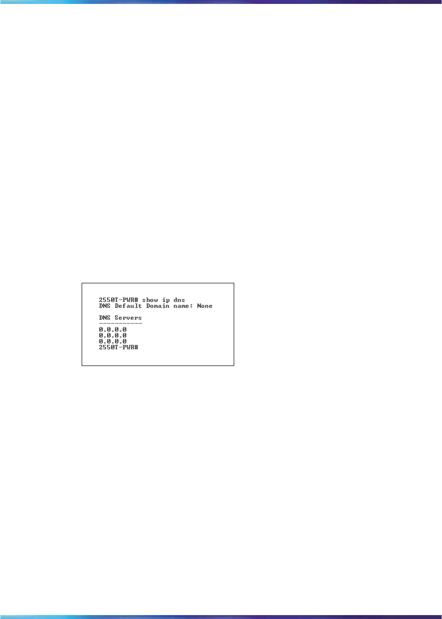
Using DNS to ping and telnet 185
•"no ip name-server command" (page 187)
•"ip domain-name command" (page 187)
•"no ip domain-name command" (page 188)
•"default ip domain-name command" (page 188)
show ip dns command
The show ip dns command displays the DNS domain name, as well as
any configured DNS servers. The syntax for the show ip dns command is:
show ip dns
The show ip dns command is executed in the User Exec command mode.
The show ip dns command has no parameters or variables.
Figure 59 "show ip dns command output" (page 185) displays sample
output from the show ip dns command.
Figure 59
show ip dns command output
ping command
The ping command tests the network connection to another network
device. The command sends an Internet Control Message Protocol (ICMP)
packet from the switch to the target device. The local IP address must be
set before issuing the ping command.
You can ping a host using either its IP address or hostname.
The syntax for the ping command is:
ping <A.B.C.D or Hostname>
The ping command is executed in the User Exec command mode.
Table 52 "ping command parameters and variables" (page 186) describes
the parameters and variables for the ping command.
Nortel Ethernet Routing Switch 2500 Series
Overview — System Configuration
NN47215-500 (323162-B) 02.02 Standard
4.1 19 November 2007
Copyright © 2007, Nortel Networks
.
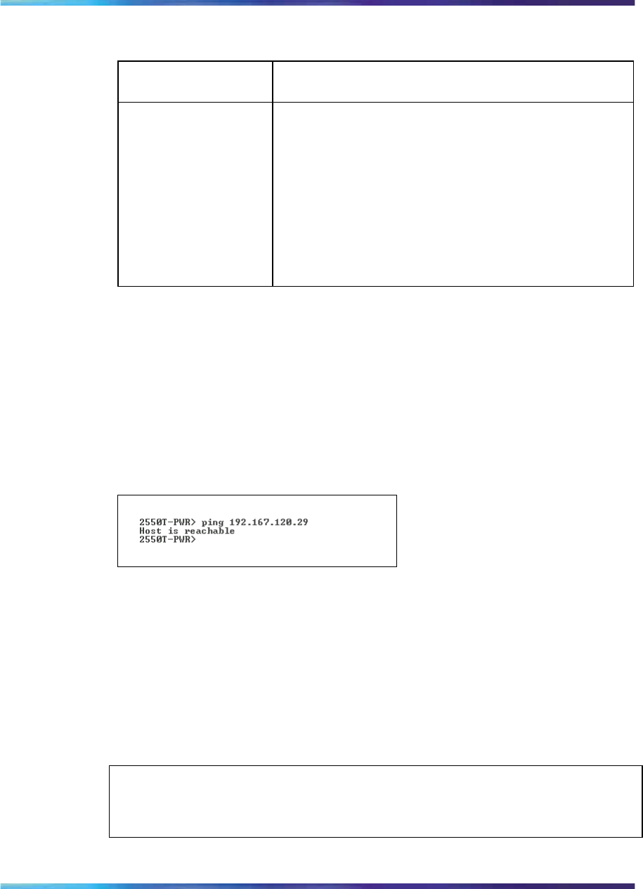
186 System configuration using the CLI
Table 52
ping command parameters and variables
Parameters and
variables Description
<A.B.C.D or
Hostname> Specify:
•the IP address of the target device in dotted-decimal
notation
•the hostname of the device to ping (The hostname
can be a simple name, such as fred; in this case
the DNS domain name, if set, is appended. Or
the hostname can be a full hostname, such as
fred.ca.nortel.com.)
If the device receives the packet, it sends a ping reply. When the switch
receives the reply, it displays a message indicating that the specified IP
address is being used. If no reply is received, a message indicates that the
address is not responding.
Figure 60 "ping command responses" (page 186) displays sample ping
responses.
Figure 60
ping command responses
There is no default value for this command.
ip name-server command
The ip name-server command adds one or more DNS servers’ IP
addresses. The syntax for the ip name-server command is:
ip name-server <A.B.C.D>
The ip name-server command is executed in the Global Configuration
command mode.
ATTENTION
You can add up to three servers; adding one at a time.
Nortel Ethernet Routing Switch 2500 Series
Overview — System Configuration
NN47215-500 (323162-B) 02.02 Standard
4.1 19 November 2007
Copyright © 2007, Nortel Networks
.

Using DNS to ping and telnet 187
Table 53 "ip name-server command parameters and variables" (page
187) describes the parameters and variables for the ip name-server
command.
Table 53
ip name-server command parameters and variables
Parameters and
variables Description
<A.B.C.D> Enter the IP address of a DNS server.
The default value is 0.0.0.0.
no ip name-server command
The no ip name-server command removes one or more DNS servers’
IP addresses. The syntax for the no ip name-server command is:
no ip name-server <A.B.C.D>
The no ip name-server command is executed in the Global
Configuration command mode.
Table 54 "no ip name-server command parameters and variables" (page
187) describes the parameters and variables for the no ip name-server
command.
Table 54
no ip name-server command parameters and variables
Parameters and
variables Description
<A.B.C.D> Enter the IP address of a DNS server.
The default value is 0.0.0.0.
ip domain-name command
The ip domain-name command sets the system’s DNS domain name.
The syntax for the ip domain-name command is:
ip domain-name [<LINE>]
The ip domain-name command is executed in the Global Configuration
command mode.
Table 55 "ip domain-name command parameters and variables" (page
188) describes the parameters and variables for the ip domain-name
command.
Nortel Ethernet Routing Switch 2500 Series
Overview — System Configuration
NN47215-500 (323162-B) 02.02 Standard
4.1 19 November 2007
Copyright © 2007, Nortel Networks
.

188 System configuration using the CLI
Table 55
ip domain-name command parameters and variables
Parameters and
variables Description
<LINE> Enter a DNS domain name.
The default value for this command is an empty string.
no ip domain-name command
The no ip domain-name command clears the system’s DNS domain
name (sets it to an empty string). The syntax for the no ip domain-name
command is:
no ip domain-name
The no ip domain-name command is executed in the Global
Configuration command mode.
The no ip domain-name command has no parameters or variables.
default ip domain-name command
The default ip domain-name command clears the system’s DNS
domain name (set it to an empty string). The syntax for the default ip
domain-name command is:
default ip domain-name
The default ip domain-name command is executed in the Global
Configuration command mode.
The default ip domain-name command has no parameters or
variables.
Configuration Management
This section covers the following topics:
•"Automatically loading Configuration file" (page 188)
•"ASCII Configuration Generator" (page 191)
Automatically loading Configuration file
This section discusses how to download a configuration file when the
system boots. You use standard CLI commands to modify the configuration
file you want to download. This section contains information about the
following commands:
•"configure network command" (page 189)
Nortel Ethernet Routing Switch 2500 Series
Overview — System Configuration
NN47215-500 (323162-B) 02.02 Standard
4.1 19 November 2007
Copyright © 2007, Nortel Networks
.

Configuration Management 189
•"show config-network command" (page 190)
configure network command
The configure network command lets you load and execute a script
immediately and to configure parameters to automatically download
a configuration file when you reboot the switch. The syntax for the
configure network command is:
configure network [load-on-boot
{disable|use-bootp|use-config}] [filename <WORD>] [address
<XXX.XXX.XXX.XXX>]
The configure network command is executed in the User Exec mode.
ATTENTION
When you enter configure network with no parameters, the system prompts
you for the script file name and TFTP server address and then downloads the
script.
Table 56 "configure network command parameters and variables" (page
189) describes the parameters and variables for the configure network
command.
Table 56
configure network command parameters and variables
Parameters and
variables Description
load-on-boot {disable|use-b
ootp|use-config Specifies the settings for automatically loading a configuration file
when the system boots:
• disable—disables the automatic loading of config file
• use-boot—specifies using the BootP file as the automatically
loaded config file
• use-config—specifies using the ASCII configuration file as the
automatically loaded config file
ATTENTION
When you enter configure network with no parameters, the
system prompts you for the script file name and TFTP server
address and then downloads the script.
If you omit this parameter, the system immediately downloads
and runs the ASCII config file.
Nortel Ethernet Routing Switch 2500 Series
Overview — System Configuration
NN47215-500 (323162-B) 02.02 Standard
4.1 19 November 2007
Copyright © 2007, Nortel Networks
.

190 System configuration using the CLI
Parameters and
variables Description
filename <WORD> Specifies the file name.
ATTENTION
If you omit this parameter and do not specify BootP, the system
uses the configured file name.
address <XXX.XXX.XXX.X
XX> Specifies the TFTP server from which to load the file. Enter the IP
address in dotted-decimal notation.
ATTENTION
If you omit this parameter and do not specify BootP, the system
uses the configured address.
ATTENTION
When you specify the file name or address, these parameters change at the next
reboot, even if you do not specify load-on-boot.
show config-network command
The show config-network command displays information regarding
the automatic loading of the configuration file, including the current status
of this feature, the file name, the TFTP server address, and the status of
the previous automatic configuration command. The syntax for the show
config-network command is:
show config-network
The show config-network command is executed in the Privileged
EXEC command mode.
The show config-network command has no parameters or values.
Figure 61 "show config-network command output" (page 191) shows the
output for the show config-network command.
Nortel Ethernet Routing Switch 2500 Series
Overview — System Configuration
NN47215-500 (323162-B) 02.02 Standard
4.1 19 November 2007
Copyright © 2007, Nortel Networks
.

Configuration Management 191
Figure 61
show config-network command output
ASCII Configuration Generator
The primary goal of the ASCII Configuration Generator (ACG) is to provide
the users of the Ethernet Routing Switch 2500 Series with a tool that lets
them easily modify configuration of a particular switch or stack.
ACG generates an ASCII configuration file which reproduces the behavior of
the current binary configuration file. The user can also rely on this function
to maintain backup configurations, as well as use it as a reliable method for
debugging the current configuration of a switch.
ATTENTION
When you are connected to a stack form the console port, ensure that the console
is on the base unit before downloading an ASCII file.
The Ethernet Routing Switch 2500 Series can download an editable ASCII
configuration file from the TFTP server. You can load the ASCII configuration
file automatically at boot time or on demand using console menus or CLI.
Once downloaded, the configuration file automatically configures the switch
according to the Command Line Interface (CLI) commands in the file. The
maximum size for an ASCII configuration file is 100 KBs; larger configuration
files must be split into multiple files.
For more information on loading the ASCII configuration file automatically,
see "Automatically loading Configuration file" (page 188).
The commands that are associated with ACG are:
•"show running-config command" (page 191)
•"copy running-config tftp command" (page 192)
show running-config command
This command displays the current configuration of switch as a series of
CLI commands.
This command must be executed in the configuration mode and has no
parameters or variables.
The syntax of this command is:
Nortel Ethernet Routing Switch 2500 Series
Overview — System Configuration
NN47215-500 (323162-B) 02.02 Standard
4.1 19 November 2007
Copyright © 2007, Nortel Networks
.
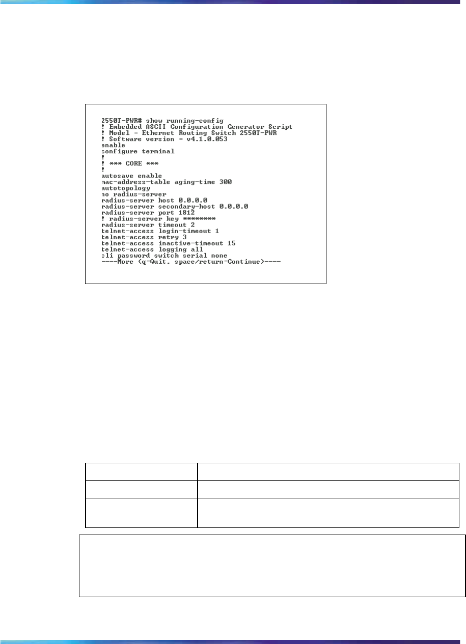
192 System configuration using the CLI
show running-config
Figure 62 "show running-config command output" (page 192) shows the
output of the show running-config command
Figure 62
show running-config command output
copy running-config tftp command
This command copies contents of the current configuration file to another
file on the TFTP server. The syntax of the command is
copy running-config tftp {<address> <filename>}
This command can be executed in the Global Configuration command mode.
Table 57 "copy running-config tftp command parameters and variables"
(page 192) describes the parameters and variables of this command.
Table 57
copy running-config tftp command parameters and variables
Parameter Description
address Signifies the IP address of the TFTP server.
filename Denotes the filename to store configuration commands
on the TFTP server.
ATTENTION
Use the copy running-config tftp command only from the base unit in
a stack.
Nortel Ethernet Routing Switch 2500 Series
Overview — System Configuration
NN47215-500 (323162-B) 02.02 Standard
4.1 19 November 2007
Copyright © 2007, Nortel Networks
.

Customizing your system 193
Customizing your system
You can customize your system using the CLI commands described in this
section. This section covers the following topics:
•"Setting the terminal" (page 193)
•"Displaying system information" (page 195)
•"Setting boot parameters" (page 196)
•"Setting TFTP parameters" (page 197)
•"Customizing the opening banner" (page 200)
Setting the terminal
You can view the terminal settings, set them to default settings, or customize
the terminal settings. This sections contains information about the following
commands:
•"show terminal command" (page 193)
•"terminal command" (page 193)
show terminal command
The show terminal command displays the current serial port information,
which includes connection speed, as well as the terminal width and length
in number of characters. The syntax for the show terminal command is:
show terminal
The show terminal command is executed in the User Exec command
mode.
The show terminal command has no parameters or variables.
Figure 63 "show terminal command output" (page 193) shows the output
from the show terminal command.
Figure 63
show terminal command output
terminal command
The terminal command configures the settings for the terminal. These
settings are transmit and receive speeds, terminal length, and terminal
width. The syntax of the terminal command is:
Nortel Ethernet Routing Switch 2500 Series
Overview — System Configuration
NN47215-500 (323162-B) 02.02 Standard
4.1 19 November 2007
Copyright © 2007, Nortel Networks
.

194 System configuration using the CLI
terminal speed {2400|4800|9600|19200|38400}|length
<1-132>|width <1-132>
The terminal command is executed in the User Exec mode.
Table 58 "terminal command parameters and variables" (page
194) describes the parameters and variables for the terminal command.
Table 58
terminal command parameters and variables
Parameters and
variables Description
speed
{2400|4800|9600|192
00|38400}
Sets the transmit and receive baud rates for the terminal.
You can set the speed at one of the five options shown;
default is 9600.
length Sets the length of the terminal display in characters;
default is 24.
width Sets the width of the terminal displaying characters;
default 79.
show cli command
The show cli command displays the current CLI settings. The syntax for
the show cli command is:
show cli {info | mode | password [type]}
The show cli command is executed in the User Exec command mode.
Table 59 "show cli command parameters and variables" (page
194) describes the parameters and variables for the show cli command.
Table 59
show cli command parameters and variables
Parameters and
variables Description
info Displays general Console settings.
mode Displays CLI mode.
password Displays CLI user names and passwords.
type Displays password types.
Figure 64 "show cli command output" (page 195) displays the output from
the show cli command.
Nortel Ethernet Routing Switch 2500 Series
Overview — System Configuration
NN47215-500 (323162-B) 02.02 Standard
4.1 19 November 2007
Copyright © 2007, Nortel Networks
.
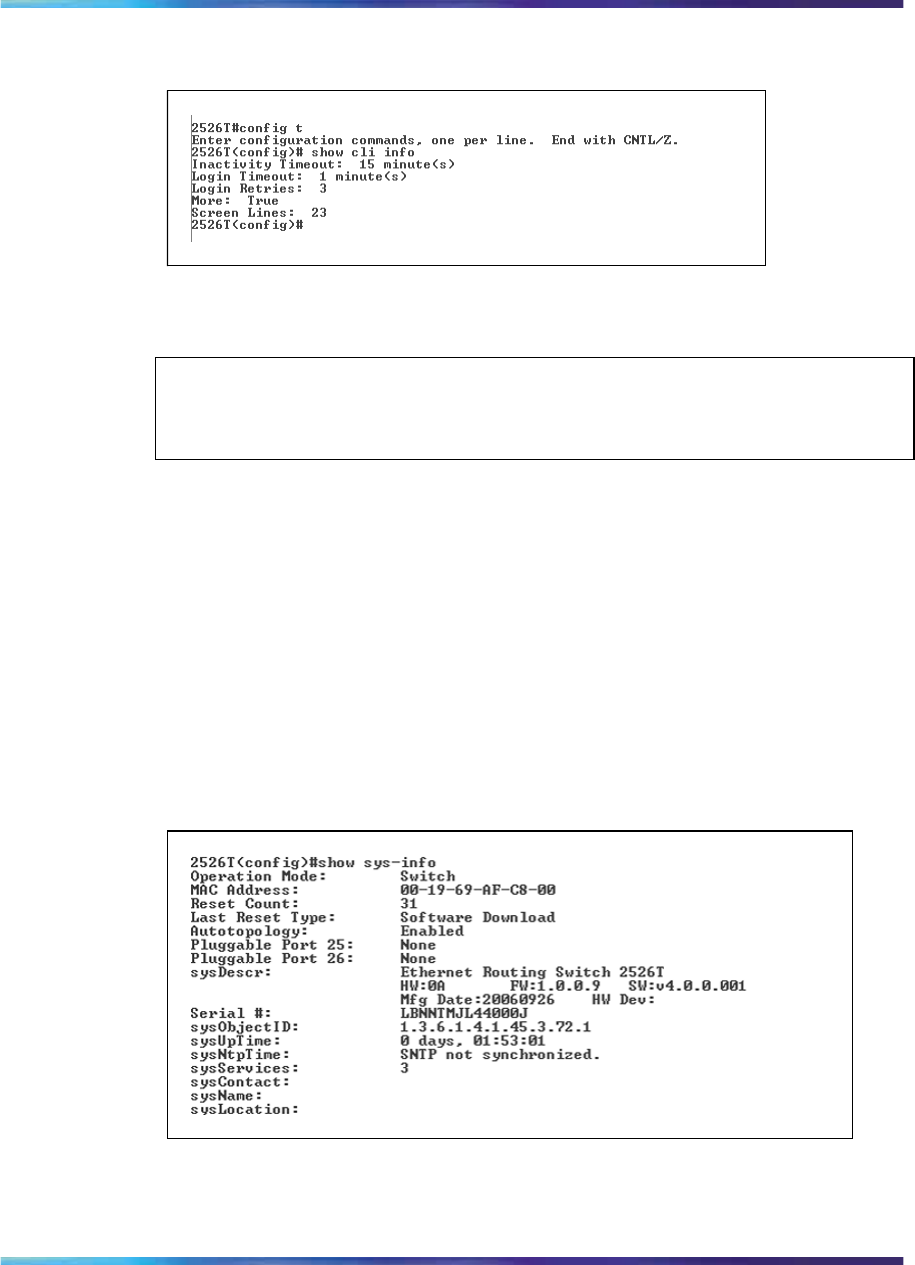
Customizing your system 195
Figure 64
show cli command output
Displaying system information
The show sys-info command displays the current system characteristics.
ATTENTION
You must have SNTP enabled and configured to display GMT time.
The syntax for the show sys-info command is:
show sys-info
The show sys-info command is executed in the Privileged EXEC
command mode.
The show sys-info command has no parameters or variables.
Figure 65 "show sys-info command output" (page 195) displays sample
output from the show sys-info command.
Figure 65
show sys-info command output
Nortel Ethernet Routing Switch 2500 Series
Overview — System Configuration
NN47215-500 (323162-B) 02.02 Standard
4.1 19 November 2007
Copyright © 2007, Nortel Networks
.

196 System configuration using the CLI
Setting boot parameters
You can reboot the switch and configure BootP. The topics covered in this
section are:
•"boot command" (page 196)
•"ip bootp server command" (page 196)
•"no ip bootp server command" (page 197)
•"default ip bootp server command" (page 197)
boot command
The boot command performs a soft-boot of the switch. The syntax for
the boot command is:
boot [default]
The boot command is executed in the Privileged EXEC command mode.
Table 60 "boot command parameters and variables" (page 196) describes
the parameters and variables for the boot command.
Table 60
boot command parameters and variables
Parameters and
variables Description
default Restores switch to factory-default settings after
rebooting.
ATTENTION
When you reset to factory defaults, the last reset count and reason for last reset
will not be set to factory defaults.
ip bootp server command
The ip bootp server command configures BootP on the current
instance of the switch or server. The syntax for the ip bootp server
command is:
ip bootp server {default-ip|last|disable|always}
The ip bootp server command is executed in the Global Configuration
command mode.
Table 61 "ip bootp server command parameters and variables" (page
197) describes the parameters and variables for the ip bootp server
command.
Nortel Ethernet Routing Switch 2500 Series
Overview — System Configuration
NN47215-500 (323162-B) 02.02 Standard
4.1 19 November 2007
Copyright © 2007, Nortel Networks
.

Customizing your system 197
Table 61
ip bootp server command parameters and variables
Parameters and
variables Description
last|needed|disable|al
ways
Specifies when to use BootP:
•default-ip—use BootP or the default IP
•last—use BootP or the last known address
•disable—never use BootP
•always—Always use BootP
no ip bootp server command
The no ip bootp server command disables the BootP server. The
syntax for the no ip bootp server command is:
no ip bootp server
The no ip bootp server command is executed in the Global
Configuration command mode.
The no ip bootp server command has no parameters or values.
default ip bootp server command
The default ip bootp server command sets the BootP server status
to BootP or Default IP. The syntax for the default ip bootp server
command is:
default ip bootp server
The default ip bootp server command is executed in the Global
Configuration command mode.
The default ip bootp server command has no parameters or values.
Setting TFTP parameters
You can display the IP address of the TFTP server, assign an IP address
you want to use for a TFTP server, copy a configuration file to the TFTP
server, or copy a configuration file from the TFTP server to the switch to use
to configure the switch. This section covers:
•"show tftp-server command" (page 198)
•"tftp-server command" (page 198)
•"default tftp-server command" (page 199)
•"no tftp-server command" (page 199)
Nortel Ethernet Routing Switch 2500 Series
Overview — System Configuration
NN47215-500 (323162-B) 02.02 Standard
4.1 19 November 2007
Copyright © 2007, Nortel Networks
.
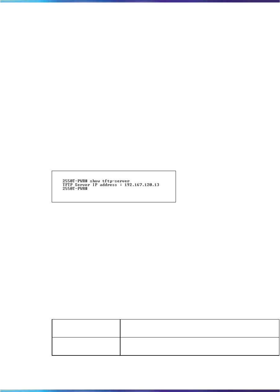
198 System configuration using the CLI
•"copy config tftp command" (page 199)
•"copy tftp config command" (page 200)
show tftp-server command
The show tftp-server command displays the IP address of the server
used for all TFTP-related transfers. The syntax for the show tftp-server
command is:
show tftp-server
The show tftp-server command is executed in the Privileged EXEC
command mode.
The show tftp-server command has no parameters or variables.
Figure 66 "show tftp-server command output" (page 198) shows a sample
output of the show tftp-server command.
Figure 66
show tftp-server command output
tftp-server command
The tftp-server command assigns the address for the switch to use for
TFTP services. The syntax of the tftp-server command is:
tftp-server <XXX.XXX.XXX.XXX>
The tftp-server command is executed in the Global Configuration
command mode.
Table 62 "tftp-server command parameters and variables" (page
198) describes the parameters and variables for the tftp-server command.
Table 62
tftp-server command parameters and variables
Parameters and
variables Description
XXX.XXX.XXX.XXX Enter the dotted-decimal IP address of the server you
want to use for TFTP services.
Nortel Ethernet Routing Switch 2500 Series
Overview — System Configuration
NN47215-500 (323162-B) 02.02 Standard
4.1 19 November 2007
Copyright © 2007, Nortel Networks
.

Customizing your system 199
no tftp-server command
The no tftp-server command clears the TFTP server IP address to
0.0.0.0. The syntax of the no tftp-server command is:
no tftp-server
The no tftp-server command is executed in the Global Configuration
command mode.
The no tftp-server command has no parameters or values.
default tftp-server command
The default tftp-server command sets the TFTP server IP address
to 0.0.0.0. The syntax of the default tftp-server command is:
default tftp-server
The default tftp-server command is executed in the Global
Configuration command mode.
The default tftp-server command has no parameters or values.
copy config tftp command
The copy config tftp command copies the current configuration file
onto the TFTP server. The syntax for the copy config tftp command is:
copy config tftp [address <XXX.XXX.XXX.XXX>] filename <WORD>
The copy config tftp command is executed in the Privileged EXEC
command mode.
Table 63 "copy config tftp command parameters and variables" (page
199) describes the parameters and variables for the copy config tftp
command.
Table 63
copy config tftp command parameters and variables
Parameters and
variables Description
address <XXX.XXX.X
XX.XXX> Specifies the TFTP server IP address; enter in
dotted-decimal notation.
filename <WORD> Specifies filename that you want to copy the
configuration file onto the TFTP server. Enter the name
you want the configuration file to have on the TFTP
server.
Nortel Ethernet Routing Switch 2500 Series
Overview — System Configuration
NN47215-500 (323162-B) 02.02 Standard
4.1 19 November 2007
Copyright © 2007, Nortel Networks
.

200 System configuration using the CLI
copy tftp config command
The copy tftp config command retrieves the system configuration file
from the TFTP server and uses the retrieved information as the current
configuration on the system.The syntax for the copy tftp config
command is:
copy tftp config [address <XXX.XXX.XXX.XXX>] filename <WORD>
The copy tftp config command is executed in the Privileged EXEC
command mode.
Table 64 "copy tftp config command parameters and variables" (page
200) describes the parameters and variables for the copy tftp config
command.
Table 64
copy tftp config command parameters and variables
Parameters and
variables Description
address <XXX.XXX.X
XX.XXX> Specifies the TFTP server IP address; enter in
dotted-decimal notation.
filename <WORD> Enter the name of the configuration file you want to copy
from the TFTP server.
Customizing the opening banner
You can customize the banner that appears when you connect to the
Ethernet Routing Switch 2500 Series. You can customize the text that reads
NORTEL. However you cannot customize the second line that reads Enter
[Ctrl]+y to begin.
The Banner Control feature provides an option to specify the banner text.
If you choose not to display the banner, the system enters the command
mode through the default command interface. You do not have to press
the Ctrl+y keys.
The Banner display that you select is used for subsequent console sessions.
For executing the new mode in the console, you must logout. For Telnet
access, all subsequent sessions use the selected mode.
This section contains information about the following commands:
•"banner command for displaying banner" (page 201)
•"show banner command" (page 201)
•"no banner command" (page 202)
Nortel Ethernet Routing Switch 2500 Series
Overview — System Configuration
NN47215-500 (323162-B) 02.02 Standard
4.1 19 November 2007
Copyright © 2007, Nortel Networks
.

Customizing your system 201
banner command for displaying banner
The banner command for displaying banner specifies the banner displayed
at startup; either static or custom. The syntax for the banner command
to display banner is:
banner [ custom | static | disabled | <1-19> LINE ]
The banner command for displaying banner is executed in the Global
Configuration command mode.
Table 65 "banner command parameters" (page 201) describes the
parameters for the banner command.
Table 65
banner command parameters
Parameters Description
static Displays the default agent-banner.
custom Displays the custom agent-banner.
disabled Skips the agent-banner display.
<1-19> LINE Fills the Nth line of the custom banner (1<N<19) with
the text specified in LINE.
show banner command
The show banner command displays the banner. The syntax for the show
banner command is:
show banner [ custom | static ]
The show banner command is executed in the Global Configuration
command mode.
Table 66 "show banner command parameters and variables" (page
201) describes the parameters for the banner command.
Table 66
show banner command parameters and variables
Parameters Description
static Displays default banner
custom Displays custom banner
(if empty) Displays static, custom or disabled status if parameter
is not entered.
Nortel Ethernet Routing Switch 2500 Series
Overview — System Configuration
NN47215-500 (323162-B) 02.02 Standard
4.1 19 November 2007
Copyright © 2007, Nortel Networks
.
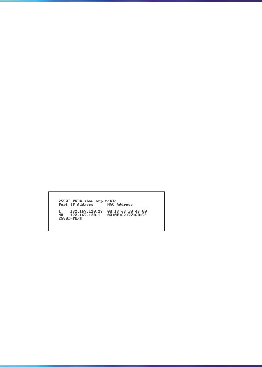
202 System configuration using the CLI
no banner command
The no banner command lets you clear all lines of a previously stored
custom banner. The syntax for the no banner command is:
no banner
The no banner command is executed in the Global Configuration
command mode.
Displaying the ARP table
The show arp-table command displays the arp table of the device. The
syntax for the show arp-table command is:
show arp-table
The show arp-table command is executed in the User Exec command
mode.
The show arp-table command has no parameters or variables.
Figure 67 "show arp-table command output" (page 202) displays a sample
output of the show arp-table command.
Figure 67
show arp-table command output
Displaying interfaces
You can view the status of all interfaces on the switch, including MultiLink
Trunk membership, link status, autonegotiation, and speed. This section
contains information about the following:
•"show interfaces command" (page 202)
•"show interfaces config command" (page 204)
show interfaces command
The show interfaces command displays the current configuration and
status of all interfaces. The syntax for the show interfaces command is:
show interfaces [names | gbic-info] [<portlist>]
The show interfaces command is executed in the User Exec command
mode.
Nortel Ethernet Routing Switch 2500 Series
Overview — System Configuration
NN47215-500 (323162-B) 02.02 Standard
4.1 19 November 2007
Copyright © 2007, Nortel Networks
.
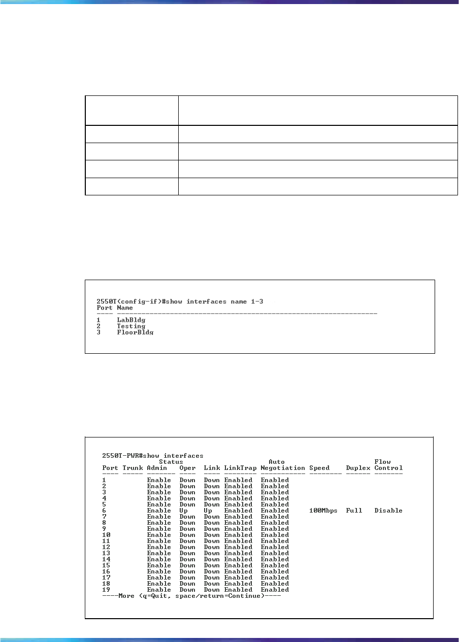
Displaying interfaces 203
Table 67 "show interfaces command parameters and variables" (page
203) describes the parameters and variables for the show interfaces
command.
Table 67
show interfaces command parameters and variables
Parameters and
variables Description
gbic-info Displays gbic details.
LINE Displays the interface information for specific ports
names Displays the interface names.
verbose Displays information about STP and EAP.
Figure 68 "show interfaces names command output" (page 203) displays a
sample output of the show interfaces names command.
Figure 68
show interfaces names command output
Figure 69 "show interfaces command output" (page 203) shows a sample
output of the show interfaces command without the names variable.
Figure 69
show interfaces command output
Nortel Ethernet Routing Switch 2500 Series
Overview — System Configuration
NN47215-500 (323162-B) 02.02 Standard
4.1 19 November 2007
Copyright © 2007, Nortel Networks
.
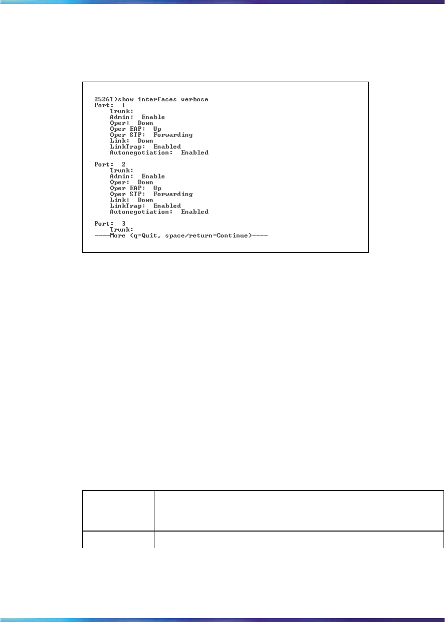
204 System configuration using the CLI
The following figure shows a sample output of the show interfaces verbose
command.
Figure 70
show interfaces verbose command output
show interfaces config command
The show interfaces config command displays the current
operational status of interfaces and provides supplementary information
about the current port settings for Spanning Tree Protocol.
The syntax for the show interfaces config command is:
show interfaces [<portlist>] config
The show interfaces config command is executed in the Privileged
EXEC command mode.
Table 68 "show interfaces config command parameters and variables"
(page 204) describes the parameters and variables for the show interfaces
config command.
Table 68
show interfaces config command parameters and variables
Parameters
and
variables Description
<portlist> Enter the ports you want to display.
Figure 71 "show interfaces config command output" (page 205) displays a
sample output of the show interfaces config command.
Nortel Ethernet Routing Switch 2500 Series
Overview — System Configuration
NN47215-500 (323162-B) 02.02 Standard
4.1 19 November 2007
Copyright © 2007, Nortel Networks
.
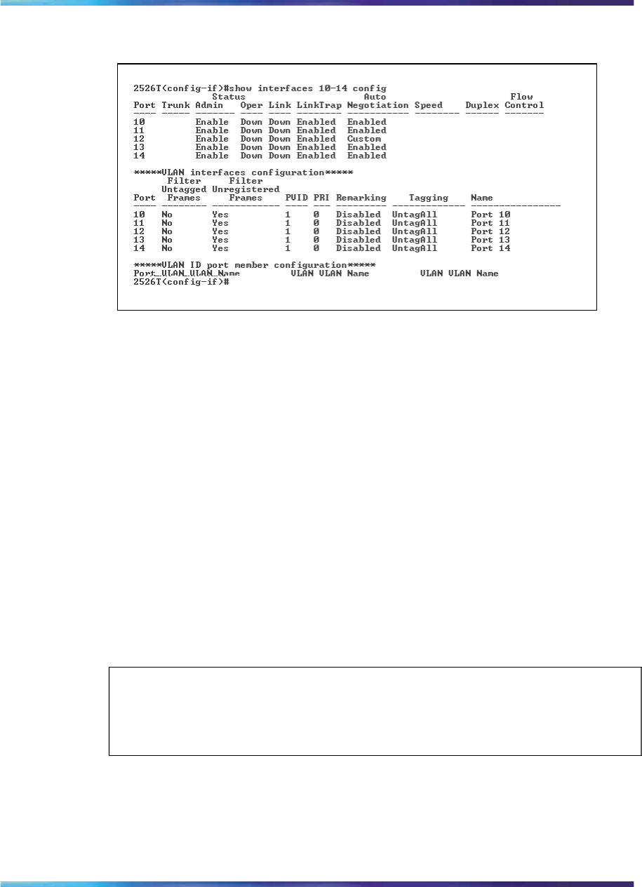
Saving the configuration to NVRAM 205
Figure 71
show interfaces config command output
Saving the configuration to NVRAM
You can save your configuration parameters to Non-Volatile RAM (NVRAM)
using any of the following CLI commands:
•"copy config nvram command" (page 205)
•"write memory command" (page 205)
•"save config command" (page 206)
copy config nvram command
The copy config nvram command copies the current configuration to
NVRAM. The syntax for the copy config nvram command is:
copy config nvram
The copy config nvram command is executed in the Privileged EXEC
command mode.
The copy config nvram command has no parameters or variables.
ATTENTION
The system automatically issues the copy config nvram command
periodically. See "Enabling and disabling autosave" (page 206) for details.
write memory command
The write memory command copies the current configuration to NVRAM.
The syntax for the write memory command is:
write memory
Nortel Ethernet Routing Switch 2500 Series
Overview — System Configuration
NN47215-500 (323162-B) 02.02 Standard
4.1 19 November 2007
Copyright © 2007, Nortel Networks
.

206 System configuration using the CLI
The write memory command is executed in the Privileged EXEC
command mode.
The write memory command has no parameters or variables.
save config command
The save config command copies the current configuration to NVRAM.
The syntax for the save config command is:
save config
The save config command is executed in the Privileged EXEC command
mode.
The save config command has no parameters or variables.
Enabling and disabling autosave
The Ethernet Routing Switch 2500 Series performs a check every 60
seconds to detect changes in the configuration file or a new log message
in the nonvolatile storage. If any of these two events occurs, the switch
automatically saves its configuration and the nonvolatile log to flash
memory. Autosave also automatically saves your configuration information
across reboots.
You can enable or disable this feature. When you disable autosave, changes
in the configuration file are not saved to the flash memory.
This section contains information about the following commands:
•"show autosave command" (page 206)
•"autosave enable command" (page 207)
•"no autosave enable command" (page 207)
•"default autosave enable command" (page 207)
ATTENTION
You can use the CLI command copy config nvram to force a manual save of
the configuration when autosave is disabled.
show autosave command
The show autosave command displays the status of the autosave feature,
either enabled or disabled. The syntax for the show autosave command
is:
show autosave
The show autosave command is executed in the Privileged EXEC
command mode.
Nortel Ethernet Routing Switch 2500 Series
Overview — System Configuration
NN47215-500 (323162-B) 02.02 Standard
4.1 19 November 2007
Copyright © 2007, Nortel Networks
.

Enabling and disabling autosave 207
The show autosave command has no parameters or variables.
Figure 72 "show autosave command output" (page 207) displays sample
output from the show autosave command.
Figure 72
show autosave command output
autosave enable command
The autosave enable command enables the autosave feature. The
syntax for the autosave enable command is:
autosave enable
The autosave enable command is executed in the Global Configuration
command mode.
The autosave enable command has no parameters or variables.
no autosave enable command
The no autosave enable command disables the autosave feature. The
syntax for the no autosave enable command is:
no autosave enable
The no autosave enable command is executed in the Global
Configuration command mode.
The no autosave enable command has no parameters or variables.
default autosave enable command
The default autosave enable command defaults the autosave feature
to the default value of enabled. The syntax for the default autosave
enable command is:
default autosave enable
The default autosave enable command is executed in the Global
Configuration command mode.
The default autosave enable command has no parameters or
variables.
Nortel Ethernet Routing Switch 2500 Series
Overview — System Configuration
NN47215-500 (323162-B) 02.02 Standard
4.1 19 November 2007
Copyright © 2007, Nortel Networks
.

208 System configuration using the CLI
Setting time on network elements using Simple Network Time
Protocol The Simple Network Time Protocol (SNTP) feature synchronizes the
Universal Coordinated Time (UTC) to an accuracy within 1 second. This
feature adheres to the IEEE RFC 2030 (MIB is the s5agent). With this
feature, the system can obtain the time from any RFC 2030-compliant
NTP/SNTP server.
ATTENTION
If you have trouble using this feature, try various NTP servers. Some NTP servers
may be overloaded or currently inoperable.
•"show sntp command" (page 208)
•"sntp enable command" (page 209)
•"no sntp enable command" (page 209)
•"sntp server primary address command" (page 209)
•"sntp server secondary address command" (page 210)
•"no sntp server command" (page 210)
•"sntp sync-now command" (page 211)
•"sntp sync-interval command" (page 211)
•"default sntp command" (page 212)
show sntp command
The show sntp command displays the SNTP information, as well as the
configured NTP servers. The syntax for the show sntp command is:
show sntp
The show sntp command is executed in the Privileged EXEC command
mode.
The show sntp command has no parameters or variables.
Figure 73 "show sntp command output" (page 209) displays sample output
from the show sntp command.
Nortel Ethernet Routing Switch 2500 Series
Overview — System Configuration
NN47215-500 (323162-B) 02.02 Standard
4.1 19 November 2007
Copyright © 2007, Nortel Networks
.
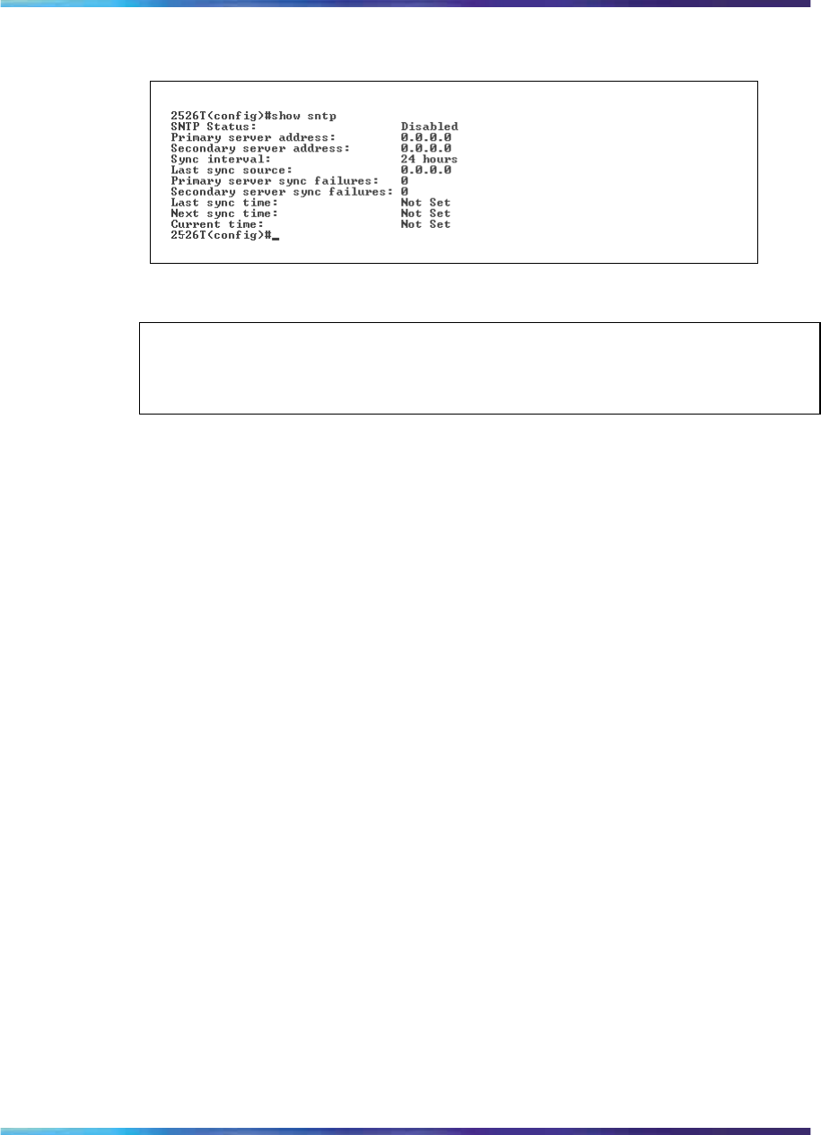
Setting time on network elements using Simple Network Time Protocol 209
Figure 73
show sntp command output
sntp enable command
ATTENTION
The default setting for SNTP is disabled.
The sntp enable command enables SNTP. The syntax for the sntp
enable command is:
sntp enable
The sntp enable command is executed in the Global Configuration
command mode.
The sntp enable command has no parameters or variables.
no sntp enable command
The no sntp enable command disables SNTP. The syntax for the no
sntp enable command is:
no sntp enable
The no sntp enable command is executed in the Global Configuration
command mode.
The no sntp enable command has no parameters or variables.
sntp server primary address command
The sntp server primary address command specifies the IP
addresses of the primary NTP server. The syntax for the sntp server
primary address command is:
sntp server primary address <A.B.C.D>
The sntp server primary address command is executed in the
Global Configuration command mode.
Nortel Ethernet Routing Switch 2500 Series
Overview — System Configuration
NN47215-500 (323162-B) 02.02 Standard
4.1 19 November 2007
Copyright © 2007, Nortel Networks
.

210 System configuration using the CLI
Table 69 "sntp server primary address command parameters and variables"
(page 210) describes the parameters and variables for the sntp server
primary address command.
Table 69
sntp server primary address command parameters and variables
Parameters and
variables Description
<A.B.C.D> Enter the IP address of the primary NTP server.
The default is 0.0.0.0.
sntp server secondary address command
The sntp server secondary address command specifies the IP
addresses of the secondary NTP server. The syntax for the sntp server
secondary address command is:
sntp server secondary address <A.B.C.D>
The sntp server secondary address command is executed in the
Global Configuration command mode.
Table 70 "sntp server secondary address command parameters and
variables" (page 210) describes the parameters and variables for the sntp
server secondary address command.
Table 70
sntp server secondary address command parameters and variables
Parameters and
variables Description
<A.B.C.D> Enter the IP address of the secondary NTP server.
The default is 0.0.0.0.
no sntp server command
The no sntp server command clears the NTP server IP addresses. The
syntax for the no sntp server command is:
no sntp server <primary|secondary>
The no sntp server command is executed in the Global Configuration
command mode.
Table 71 "no sntp server command parameters and variables" (page
211) describes the parameters and variables for the no sntp server
command.
Nortel Ethernet Routing Switch 2500 Series
Overview — System Configuration
NN47215-500 (323162-B) 02.02 Standard
4.1 19 November 2007
Copyright © 2007, Nortel Networks
.

Setting time on network elements using Simple Network Time Protocol 211
Table 71
no sntp server command parameters and variables
Parameters and
variables Description
<primary|secondary> Enter the NTP server you want to clear:
•primary—the IP address for the primary NTP
server
•secondary—the IP address for the secondary NTP
server
sntp sync-now command
The sntp sync-now command forces a manual synchronization with the
NTP server.
ATTENTION
You must have SNTP enabled before this command can take effect.
The syntax for the sntp sync-now command is:
sntp sync-now
The sntp sync-now command is executed in the Global Configuration
command mode.
The sntp sync-now command has no parameters or variables.
sntp sync-interval command
The sntp sync-interval command specifies recurring synchronization
with the NTP server in hours relative to initial synchronization. The syntax
for the sntp sync-interval command is:
sntp sync-interval <0-168>
The sntp sync-interval command is executed in the Global
Configuration command mode.
Table 72 "sntp sync-interval command parameters and variables" (page
212) describes the parameters and variables for the sntp sync-interval
command.
Nortel Ethernet Routing Switch 2500 Series
Overview — System Configuration
NN47215-500 (323162-B) 02.02 Standard
4.1 19 November 2007
Copyright © 2007, Nortel Networks
.

212 System configuration using the CLI
Table 72
sntp sync-interval command parameters and variables
Parameters and
variables Description
<0-168>
Enter the number of hours you want for periodic
synchronization with the NTP server.
ATTENTION
0 is boot-time only, and 168 is once a week; the default
value is 24 hours.
default sntp command
The default sntp command sets the SNTP parameters to their default
values. The syntax for the default sntp command is:
default sntp [enable | server | sync-interval]
The default sntp command is executed in the Global Configuration
command mode.
Table 73 "default sntp command parameters and variables" (page
212) describes the parameters and variables for the default sntp command.
Table 73
default sntp command parameters and variables
Parameters and
variables Description
enable Disables SNTP.
server Clears stored SNTP server addresses.
sync-interval Restores the default SNTP re-synchronization interval.
Setting local time zone
SNTP uses Universal Coordinated Time (UTC) for all time synchronizations
so it is not affected by different time zones. In order for the switch report
the correct time for your local time zone and daylight savings time, you
must use the following commands:
•"clock time-zone" (page 213)
•"no clock time-zone" (page 213)
•"clock summer-time" (page 213)
Nortel Ethernet Routing Switch 2500 Series
Overview — System Configuration
NN47215-500 (323162-B) 02.02 Standard
4.1 19 November 2007
Copyright © 2007, Nortel Networks
.

Setting local time zone 213
•"no clock summer-time" (page 214)
•"show clock time-zone" (page 214)
•"show clock summer-time" (page 215)
clock time-zone
The clock time-zone command sets the local time zone relative to
Universal Coordinated Time (UTC). The syntax for the clock time-zone
command is:
clock time-zone <zone> <hours> <minutes>
The clock time-zone command is executed in the Global Configuration
command mode.
Table 74 "clock time-zone command parameters and variables" (page
213) describes the parameters and variables for the clock time-zone
command.
Table 74
clock time-zone command parameters and variables
Parameters and
variables Description
zone Time zone acronym that can be displayed when showing
system time (Range: Up to 4 characters)
hours Hours difference from UTC. (Valid Range: –12 to +12)
minutes Optional minutes difference from UTC. (Range: 0–59)
no clock time-zone
The no clock time-zone command disables the clock time zone
feature. The syntax for the no clock time-zone command is:
no clock time-zone
The no clock time-zone command is executed in the Global
Configuration command mode.
The no clock time-zone command has no parameters or variables.
clock summer-time
The clock summer-time command sets the daylight savings time with
start and end dates. The syntax for the clock summer-time command is:
clock summer-time <zone> [date {<day> <month> <year>
<hh:mm>} {<day> <month> <year> <hh:mm>}] [<offset>]
Nortel Ethernet Routing Switch 2500 Series
Overview — System Configuration
NN47215-500 (323162-B) 02.02 Standard
4.1 19 November 2007
Copyright © 2007, Nortel Networks
.

214 System configuration using the CLI
The clock summer-time command is executed in the Global
Configuration command mode.
Table 75 "clock summer-time command parameters and variables" (page
214) describes the parameters and variables for the clock summer-time
command.
Table 75
clock summer-time command parameters and variables
Parameters and
variables Description
zone The acronym to display when summer time is in effect. If
unspecified default to the time zone acronym. (Range: up
to 4 characters)
date {<day>
<month> <year>
<hh:mm>} {<day>
<month> <year>
<hh:mm>}
The first date specifies when summer time should start
and the second date specifies when summer time
should end.
• day: day of the month (Range: 1 to 31)
• month: month (Range: first three letters by name)
• hh:mm: time in military format, in hours and minutes
ATTENTION
<day> <month> parameters can also be entered in
order: <month> <day>.
offset Number of minutes to add during summer time (Range:
-840 to 840).
no clock summer-time
The no clock summer-time command disables the daylight savings
time feature. The syntax for the no clock summer-time command is:
no clock summer-time
The no clock summer-time command is executed in the Global
Configuration command mode.
The no clock time-zone command has no parameters or variables.
show clock time-zone
The show clock time-zone command displays the local time zone
settings. The syntax for the show clock time-zone command is:
Nortel Ethernet Routing Switch 2500 Series
Overview — System Configuration
NN47215-500 (323162-B) 02.02 Standard
4.1 19 November 2007
Copyright © 2007, Nortel Networks
.
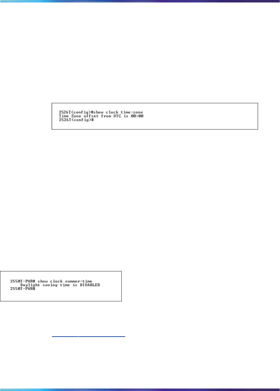
Enabling Autopology 215
show clock time-zone
The show clock time-zone command is executed in the Global
Configuration command mode.
The show clock time-zone command has no parameters or variables.
Figure 74 "show clock time-zone output" (page 215) displays sample output
from the show clock time-zone command.
Figure 74
show clock time-zone output
show clock summer-time
The show clock summer-time command displays the daylight savings
time settings. The syntax for the show clock summer-time command is:
show clock summer-time
The show clock summer-time command is executed in the Global
Configuration command mode.
The show clock summer-time command has no parameters or
variables.
Figure 75 "show clock summer-time" (page 215) displays sample output
from the show clock summer-time command.
Figure 75
show clock summer-time
Enabling Autopology
You can enable the Optivity* Autopology* protocol using the CLI. See
www.nortel.com/support for information on Autopology. (The product family
for Optivity and Autotopology is Data and Internet.) This section covers the
following commands:
•"autotopology command" (page 216)
•"no autotopology command" (page 216)
Nortel Ethernet Routing Switch 2500 Series
Overview — System Configuration
NN47215-500 (323162-B) 02.02 Standard
4.1 19 November 2007
Copyright © 2007, Nortel Networks
.

216 System configuration using the CLI
•"default autotopology command" (page 216)
autotopology command
The autotopology command enables the Autotopology protocol. The
syntax for the autotopology command is:
autotopology
The autotopology command is executed in the Global Configuration
command mode.
The autotopology command has no parameters or values.
no autotopology command
The no autotopology command disables the Autotopology protocol. The
syntax for the no autotopology command is:
no autotopology
The no autotopology command is executed in the Global Configuration
command mode.
The no autotopology command has no parameters or values.
default autotopology command
The default autotopology command enables the Autotopology
protocol. The syntax for the default autotopology command is:
default autotopology
The default autotopology command is executed in the Global
Configuration command mode.
The default autotopology command has no parameters or values.
show autotopology settings
The show autotopology settings command displays information on
the Autotopology configuration. The syntax for the
show autotopology settings command is:
show autotopology settings
The show autotopology settings command is executed in the
Privileged EXEC command mode.
The show autotopology settings command has no parameters or
variables.
Nortel Ethernet Routing Switch 2500 Series
Overview — System Configuration
NN47215-500 (323162-B) 02.02 Standard
4.1 19 November 2007
Copyright © 2007, Nortel Networks
.
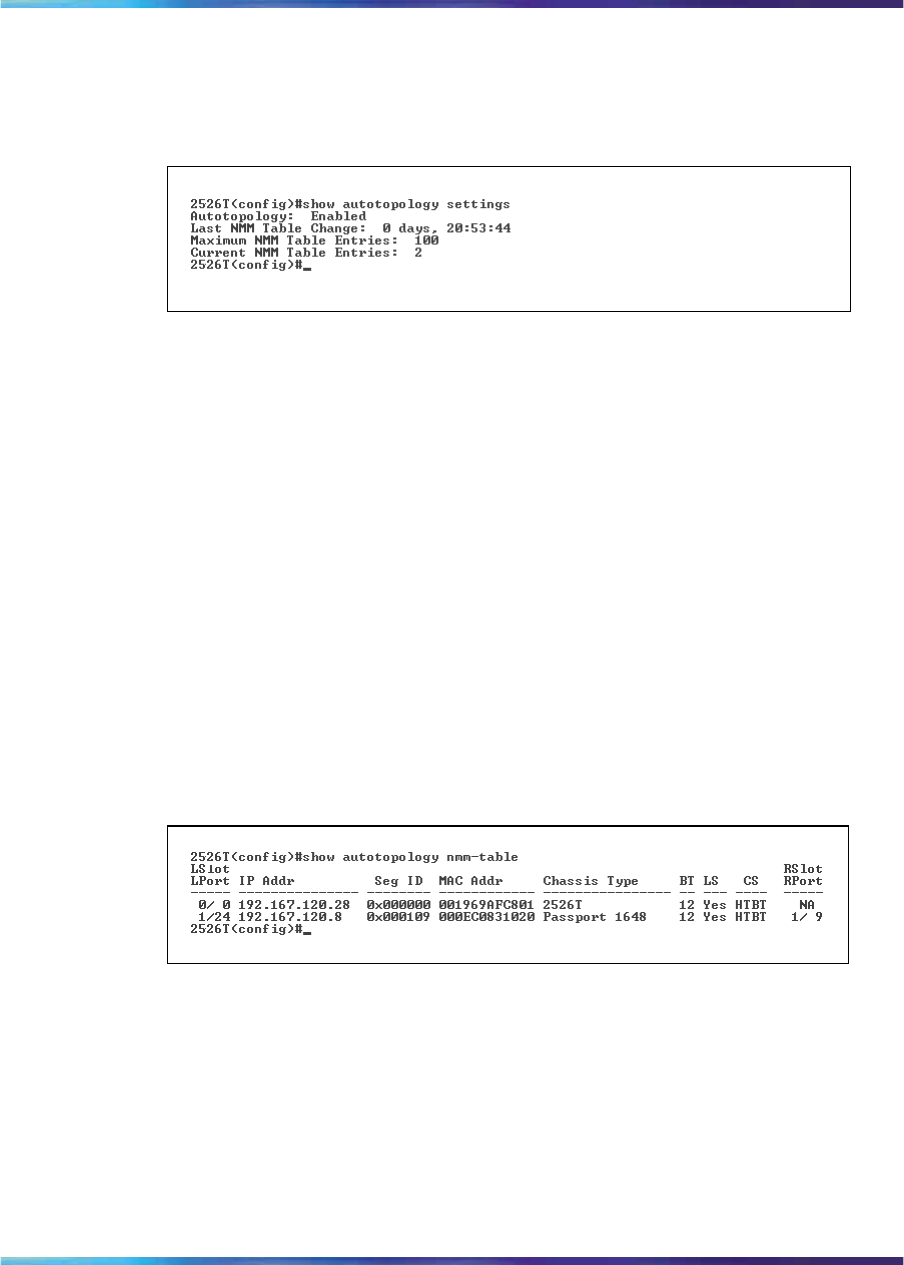
Configuring LLDP using the CLI 217
Figure 76 "show autotopology settings command output" (page 217) displays
a sample output of the show autotopology settings command.
Figure 76
show autotopology settings command output
show autotopology nmm-table
The show autotopology nmm-table command displays information
about the network management module (NMM) table. The syntax for the
show autotopology nmm-table command is:
show autotopology nmm-table
The show autotopology nmm-table command is executed in the
Privileged EXEC command mode.
The show autotopology nmm-table command has no parameters
or variables.
Figure 77 "show autotopology nmm-table command output" (page
217) displays a sample output of the show autotopology nmm-table
command.
Figure 77
show autotopology nmm-table command output
Configuring LLDP using the CLI
You can enable the LLDP using the CLI. For more information about LLDP,
see "Link Layer Discovery Protocol (IEEE 802.1ab)" (page 74). This section
covers the following commands:
•"lldp command" (page 218)
•"default lldp command" (page 219)
•"lldp config-notification command" (page 219)
Nortel Ethernet Routing Switch 2500 Series
Overview — System Configuration
NN47215-500 (323162-B) 02.02 Standard
4.1 19 November 2007
Copyright © 2007, Nortel Networks
.

218 System configuration using the CLI
•"no lldp config-notification command" (page 220)
•"default lldp config-notification command" (page 220)
•"lldp tx-tlv command" (page 221)
•"no lldp tx-tlv command" (page 221)
•"default lldp tx-tlv command" (page 222)
•"lldp status command" (page 222)
•"no lldp status command" (page 223)
•"default lldp status command" (page 223)
•"show lldp command" (page 224)
•"show lldp port command" (page 226)
lldp command
The lldp command sets the LLDP transmission parameters. The syntax
for the lldp command is:
lldp [tx-interval <5-32768>] [tx-hold-multiplier <2-10>]
[reinit-delay <1-10>] [tx-delay <1-8192>]
[notification-interval <5-3600>]
The lldp command is executed in the Global Configuration command
mode.
Table 76 "lldp command parameters and variables" (page 218) describes
the parameters and variables for the lldp command.
Table 76
lldp command parameters and variables
Parameters and
variables Description
tx-interval
<5-32768>
Sets the interval between successive transmission cycles.
tx-hold-multiplier
<2-10>
Sets the multiplier for tx-interval used to compute the Time
To Live value for the TTL TLV.
reinit-delay
<1-10>
Sets the delay for re-initialization attempt if the adminStatus
is disabled.
tx-delay <1-8192
>
Sets the minimum delay between successive LLDP frame
transmissions.
notification-interva
l<5-3600>
Sets the interval between successive transmissions of LLDP
notifications.
Nortel Ethernet Routing Switch 2500 Series
Overview — System Configuration
NN47215-500 (323162-B) 02.02 Standard
4.1 19 November 2007
Copyright © 2007, Nortel Networks
.

Configuring LLDP using the CLI 219
default lldp command
The default lldp command sets the LLDP transmission parameters to
their default values. The syntax for the default lldp command is:
default lldp [tx-interval] [tx-hold-multiplier]
[reinit-delay] [tx-delay] [notification-interval]
If no parameters are specified, the default lldp command sets all
parameters to their default values.
The default lldp command is executed in the Global Configuration
command mode.
Table 77 "default lldp command parameters and variables" (page
219) describes the parameters and variables for the default lldp command.
Table 77
default lldp command parameters and variables
Parameters and
variables Description
tx-interval Sets retransmit interval to the default value (30).
tx-hold-multiplier Sets transmission multiplier to the default value (4).
reinit-delay Sets reinitialize delay to the default value (2).
tx-delay Sets transmission delay to the default value (2).
notification-interva
lSets notification interval to the default value (5).
lldp config-notification command
The lldp config-notification command enables notification when
new neighbor information is stored or when existing information is removed.
The syntax for the lldp config-notification command is:
lldp [port <portlist>] config-notification
The lldp config-notification command is executed in the Interface
Configuration command mode.
Table 78 "lldp config-notification command parameters and variables" (page
220) describes the parameters and variables for the lldp config-notification
command.
Nortel Ethernet Routing Switch 2500 Series
Overview — System Configuration
NN47215-500 (323162-B) 02.02 Standard
4.1 19 November 2007
Copyright © 2007, Nortel Networks
.

220 System configuration using the CLI
Table 78
lldp config-notification command parameters and variables
Parameters and
variables Description
<portlist> Specifies the ports affected by the command.
no lldp config-notification command
no lldp config-notification command disables config notification.
The syntax for the no lldp config-notification command is:
no lldp [port <portlist>] config-notification
The no lldp config-notification command is executed in the
Interface Configuration command mode.
Table 79 "no lldp config-notification command parameters and variables"
(page 220) describes the parameters and variables for the no lldp
config-notification command.
Table 79
no lldp config-notification command parameters and variables
Parameters and
variables Description
<portlist> Specifies the ports affected by the command.
default lldp config-notification command
The default lldp config-notification command sets config
notification to its default value (disabled). The syntax for the default
lldp config-notification command is:
default lldp [port <portlist>] config-notification
The default lldp config-notification command is executed in
the Interface Configuration command mode.
Table 80 "default lldp config-notification command parameters and variables"
(page 220) describes the parameters and variables for the default lldp
config-notification command.
Table 80
default lldp config-notification command parameters and variables
Parameters and
variables Description
line <portlist> Specifies the ports affected by the command.
Nortel Ethernet Routing Switch 2500 Series
Overview — System Configuration
NN47215-500 (323162-B) 02.02 Standard
4.1 19 November 2007
Copyright © 2007, Nortel Networks
.

Configuring LLDP using the CLI 221
lldp tx-tlv command
The lldp tx-tlv command specifies the optional TLVs to include in the
transmitted LLDPDUs. The syntax for the lldp tx-tlv command is:
lldp tx-tlv [port <portlist>] [local-mgmt-addr] [port-desc]
[sys-cap] [sys-desc] [sys-name]
The lldp tx-tlv command is executed in the Interface Configuration
command mode.
Table 81 "lldp tx-tlv command parameters and variables" (page
221) describes the parameters and variables for the lldp tx-tlv command.
Table 81
lldp tx-tlv command parameters and variables
Parameters and
variables Description
port <portlist> Specifies the ports affected by the command.
local-mgmt-addr Local management address TLV
port-desc Port description TLV
sys-cap System capabilities TLV
sys-desc System description TLV
sys-name System name TLV
no lldp tx-tlv command
The no lldp tx-tlv command specifies the optional TLVs not to include
in the transmitted LLDPDUs. The syntax for the lldp tx-tlv command is:
no lldp tx-tlv [port <portlist>] [local-mgmt-addr]
[port-desc]
[sys-cap] [sys-desc] [sys-name]
The no lldp tx-tlv command is executed in the Interface Configuration
command mode.
Table 82 "no lldp tx-tlv command parameters and variables" (page
221) describes the parameters and variables for the no lldp tx-tlv command.
Table 82
no lldp tx-tlv command parameters and variables
Parameters and
variables Description
port <portlist> Specifies the ports affected by the command.
local-mgmt-addr Local management address TLV
Nortel Ethernet Routing Switch 2500 Series
Overview — System Configuration
NN47215-500 (323162-B) 02.02 Standard
4.1 19 November 2007
Copyright © 2007, Nortel Networks
.

222 System configuration using the CLI
Parameters and
variables Description
port-desc Port description TLV.
sys-cap System capabilities TLV
sys-desc System description TLV
sys-name System name TLV
default lldp tx-tlv command
The default lldp tx-tlv command specifies the optional TLVs not
to include in the transmitted LLDPDUs (by default, the optional TLVs are
not included in LLDPDUs). The syntax for the default lldp tx-tlv
command is:
default lldp tx-tlv [port <portlist>] [local-mgmt-addr]
[port-desc]
[sys-cap] [sys-desc] [sys-name]
The default lldp tx-tlv command is executed in the Interface
Configuration command mode.
Table 83 "default lldp tx-tlv command parameters and variables" (page
222) describes the parameters and variables for the default lldp tx-tlv
command.
Table 83
default lldp tx-tlv command parameters and variables
Parameters and
variables Description
port <portlist> Specifies the ports affected by the command.
local-mgmt-addr Local management address TLV (default value is false: not
included)
port-desc Port description TLV. (default value is false: not included)
sys-cap System capabilities TLV (default value is false: not included)
sys-desc System description TLV (default value is false: not included)
sys-name System name TLV (default value is false: not included)
lldp status command
The lldp status command sets the LLDPU transmit and receive status
on ports. The syntax for the lldp status command is:
lldp [port <portlist>] status [rxOnly | txAndRx | txOnly]
Nortel Ethernet Routing Switch 2500 Series
Overview — System Configuration
NN47215-500 (323162-B) 02.02 Standard
4.1 19 November 2007
Copyright © 2007, Nortel Networks
.

Configuring LLDP using the CLI 223
The lldp status command is executed in the Interface Configuration
command mode.
Table 84 "lldp status command parameters and variables" (page
223) describes the parameters and variables for the lldp status command.
Table 84
lldp status command parameters and variables
Parameters and
variables Description
port <portlist> Specifies the ports affected by the command.
rxOnly
txAndRx
txOnly
Enables LLDPU receive only.
Enables LLDPU transmit and receive.
Enables LLDPU transmit only.
no lldp status command
The no lldp status command disables 802.1ab on ports. The syntax
for the no lldp status command is:
no lldp [port <portlist>] status
The no lldp status command is executed in the Interface Configuration
command mode.
Table 85 "no lldp status command parameters and variables" (page
223) describes the parameters and variables for the no lldp status command.
Table 85
no lldp status command parameters and variables
Parameters and
variables Description
port <portlist> Specifies the ports affected by the command.
default lldp status command
The default lldp status command sets the LLDPU transmit and
receive status on specified ports to its default value (txAndRx). The syntax
for the default lldp status command is:
default lldp [port <portlist>] status
The default lldp status command is executed in the Interface
Configuration command mode.
Nortel Ethernet Routing Switch 2500 Series
Overview — System Configuration
NN47215-500 (323162-B) 02.02 Standard
4.1 19 November 2007
Copyright © 2007, Nortel Networks
.

224 System configuration using the CLI
Table 86 "default lldp status command parameters and variables" (page
224) describes the parameters and variables for the default lldp status
command.
Table 86
default lldp status command parameters and variables
Parameters and
variables Description
port <portlist> Specifies the ports affected by the command.
show lldp command
The show lldp command displays configuration data for LLDP. The syntax
for the show lldp command is:
show lldp [local-sys-data] [mgmt-sys-data] [pdu-tlv-size]
[stats]
The show lldp command is executed in the User Exec command mode.
Table 87 "show lldp command parameters and variables" (page
224) describes the parameters and variables for the show lldp command.
Table 87
show lldp command parameters and variables
Parameters and
variables Description
local-sys-data Displays local LLDP system data.
mgmt-sys-data Displays LLDP management data.
pdu-tlv-size Displays 802.1ab tlv in pdu.
stats Displays LLDP statistics.
Figure 78 "show lldp local-sys-data command output" (page 225) displays
the output from the show lldp local-sys-data command.
Nortel Ethernet Routing Switch 2500 Series
Overview — System Configuration
NN47215-500 (323162-B) 02.02 Standard
4.1 19 November 2007
Copyright © 2007, Nortel Networks
.
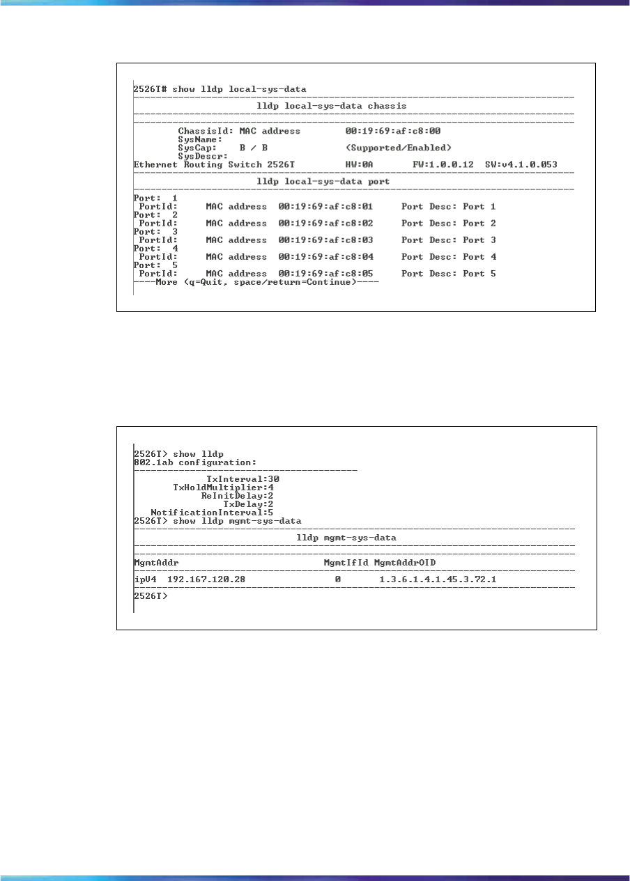
Configuring LLDP using the CLI 225
Figure 78
show lldp local-sys-data command output
Figure 79 "show lldp mgmt-sys-data command output" (page 225) displays
the output from the show lldp mgmt-sys-data command.
Figure 79
show lldp mgmt-sys-data command output
Figure 80 "show lldp stats command output" (page 226) displays the output
from the show lldp stats command.
Nortel Ethernet Routing Switch 2500 Series
Overview — System Configuration
NN47215-500 (323162-B) 02.02 Standard
4.1 19 November 2007
Copyright © 2007, Nortel Networks
.
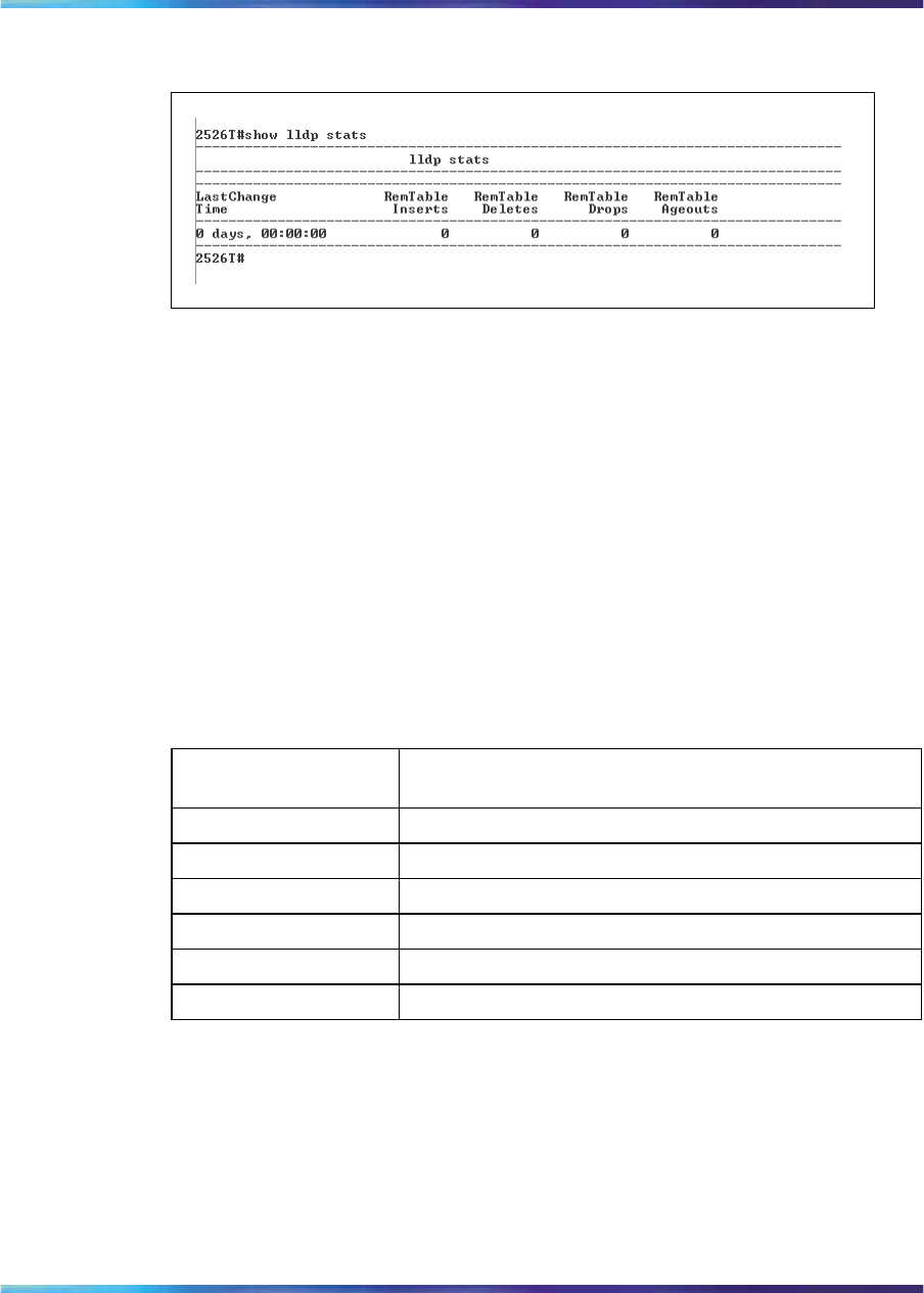
226 System configuration using the CLI
Figure 80
show lldp stats command output
show lldp port command
The show lldp port command displays configuration data for LLDP
ports. The syntax for the show lldp port command is:
show lldp [port <portlist>] [neighbor] [neighbor-mgmt-addr]
[rx-stats] [tx-stats] [tx-tlv]
The show lldp port command is executed in the User Exec command
mode.
Table 88 "show lldp port command parameters and variables" (page
226) describes the parameters and variables for the show lldp port
command.
Table 88
show lldp port command parameters and variables
Parameters and
variables Description
port <portlist> Specifies the ports affected by the command.
neighbor Displays LLDP neighbors.
neighbor-mgmt-addr Displays LLDP management addresses for neighbors.
rx-stats Displays LLDP receive statistics.
tx-stats Displays LLDP transmit statistics.
tx-tlv Displays LLDP transmit TLVs.
Figure 81 "show lldp port neighbor command output" (page 227) displays
the output from the show lldp port neighbor command.
Nortel Ethernet Routing Switch 2500 Series
Overview — System Configuration
NN47215-500 (323162-B) 02.02 Standard
4.1 19 November 2007
Copyright © 2007, Nortel Networks
.
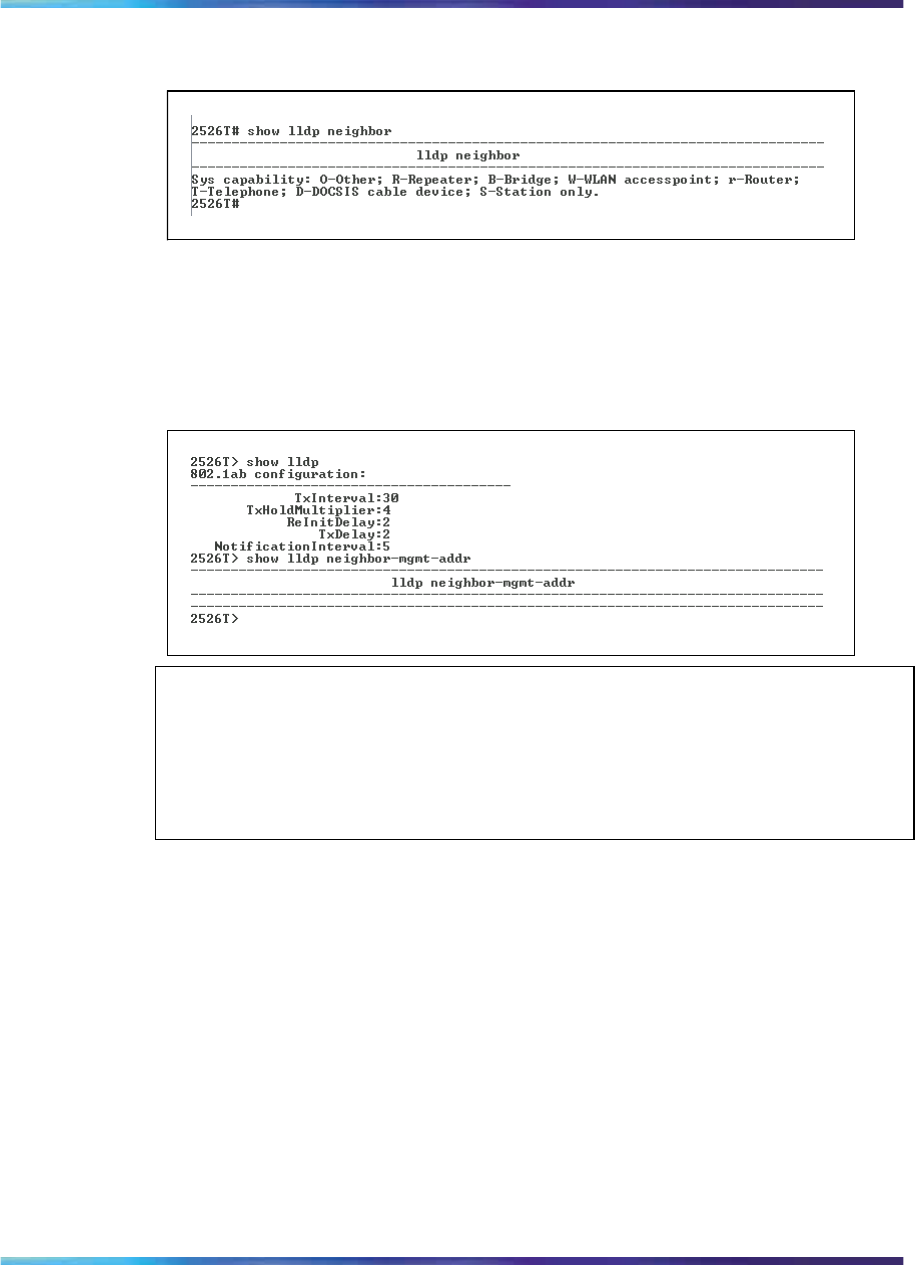
Configuring LLDP using the CLI 227
Figure 81
show lldp port neighbor command output
Figure 82 "show lldp port neighbor-mgmt-addr command output" (page
227) displays the output from the show lldp port neighbor-mgmt-addr
command.
Figure 82
show lldp port neighbor-mgmt-addr command output
ATTENTION
To display the neighbor management addresses using the show lldp port
neighbor-mgmt-addr command, you must configure the connected port of the
neighbor to transmit local management address TLVs (lldp tx-tlv [port
<portlist>] local-mgmt-addr).
Figure 83 "show lldp port rx-stats command output" (page 228) displays the
output from the show lldp rx-stats command.
Nortel Ethernet Routing Switch 2500 Series
Overview — System Configuration
NN47215-500 (323162-B) 02.02 Standard
4.1 19 November 2007
Copyright © 2007, Nortel Networks
.
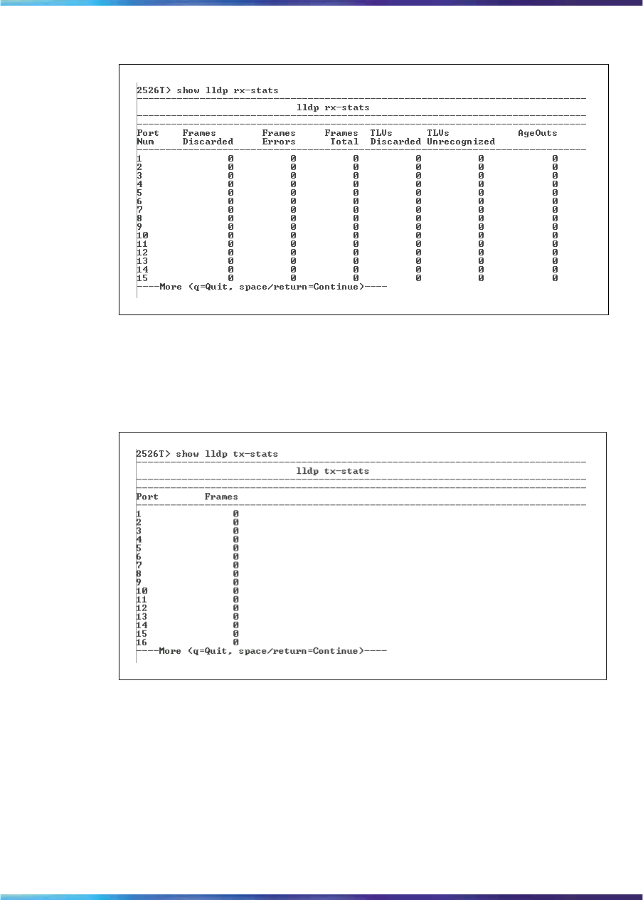
228 System configuration using the CLI
Figure 83
show lldp port rx-stats command output
Figure 84 "show lldp port tx-stats command output" (page 228) displays the
output from the show lldp tx-stats command.
Figure 84
show lldp port tx-stats command output
Figure 85 "show lldp port tx-tlv command output" (page 229) displays the
output from the show lldp stats command.
Nortel Ethernet Routing Switch 2500 Series
Overview — System Configuration
NN47215-500 (323162-B) 02.02 Standard
4.1 19 November 2007
Copyright © 2007, Nortel Networks
.
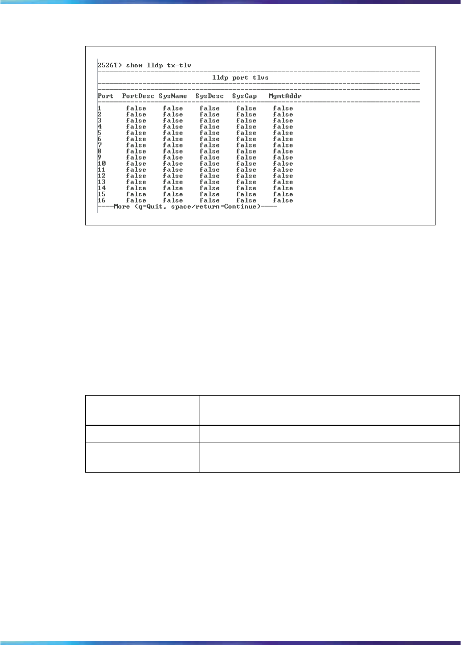
Upgrading software 229
Figure 85
show lldp port tx-tlv command output
Configuring LEDs to blink on the display panel
With the blink-leds command, you can set the LEDs on the display
panel to blink to identify a particular unit. The syntax for the blink-leds
command is:
blink-leds [off | time <1-10>]
The blink-leds command is executed in the Privileged EXEC command
mode.
Table 89
blink-leds command parameters and variables
Parameters and
variables Description
off Sets the LEDs to stop blinking.
time <1-10> Indicates the duration, in minutes, for the LEDs to blink
in order to identify the unit.
Upgrading software
You can download the Ethernet Routing Switch 2500 Series software image
that is located in nonvolatile flash memory. To download the Ethernet
Routing Switch 2500 Series software image, a properly configured Trivial
File Transfer Protocol (TFTP) server must be present in your network, and
the Ethernet Routing Switch 2500 Series must have an IP address. To
learn how to configure the switch IP address, see "Assigning and clearing
IP addresses" (page 178).
Nortel Ethernet Routing Switch 2500 Series
Overview — System Configuration
NN47215-500 (323162-B) 02.02 Standard
4.1 19 November 2007
Copyright © 2007, Nortel Networks
.

230 System configuration using the CLI
CAUTION
Do not interrupt power to the device during the software download
process. A power interruption can corrupt the firmware image.
This section contains information about the following:
•"download command" (page 230)
download command
The download command upgrades the software for the Ethernet Routing
Switch 2500 Series. You can upgrade both the software image and the
diagnostics image.
ATTENTION
The system resets after downloading a new image.
The syntax for the download command is:
download [address <ip>] {image <image-name>|image-if-newer
<image-name>|diag <filename> [no-reset] | poe-module-image }
The download command is executed in the Privileged EXEC command
mode.
ATTENTION
You can use the download command without parameters. The system displays
the most recently used TFTP server IP address and file name; if you still want to
use these, press Enter. You can also change these.
Table 90 "download command parameters and variables" (page
230) describes the parameters and variables for the download command.
Table 90
download command parameters and variables
Parameters and
variables Description
address <ip> Specifies the IP address of the TFTP server you want to
use.
Nortel Ethernet Routing Switch 2500 Series
Overview — System Configuration
NN47215-500 (323162-B) 02.02 Standard
4.1 19 November 2007
Copyright © 2007, Nortel Networks
.
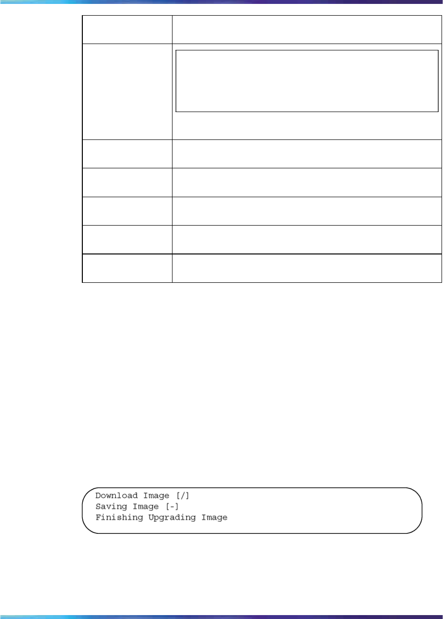
Upgrading software 231
Parameters and
variables Description
ATTENTION
If this parameter is omitted, the system goes to the
server specified by the tftp-server command.
image <image-na
me> Enter the name of the Ethernet Routing Switch 2500 Series
software image you want to download.
image-if-newer
<image-name> Enter the name of the Ethernet Routing Switch 2500 Series
software image of the newer version you want to download.
diag <filename> Enter the name of the Ethernet Routing Switch 2500 Series
diagnostics image you want to download.
no-reset Download the specified software without resetting the unit
or stack.
poe-module-imag
eSpecifies the name of the PoE image file.
The software download process automatically completes without user
intervention. The process erases the contents of flash memory and replaces
it with a new software image. Take care not to interrupt the download
process until after it runs to completion (the process can take up to 10
minutes, depending on network conditions).
When the download process is complete, the switch automatically resets
and the new software image initiates a self-test. The system returns a
message after successfully downloading a new image.
Figure 86 "download message" (page 231) shows a sample output of the
download command.
Figure 86
download message
During the download process, the Ethernet Routing Switch 2500 Series is
not operational. You can monitor the progress of the download process
by observing the LED indications.
Nortel Ethernet Routing Switch 2500 Series
Overview — System Configuration
NN47215-500 (323162-B) 02.02 Standard
4.1 19 November 2007
Copyright © 2007, Nortel Networks
.

232 System configuration using the CLI
Nortel Ethernet Routing Switch 2500 Series
Overview — System Configuration
NN47215-500 (323162-B) 02.02 Standard
4.1 19 November 2007
Copyright © 2007, Nortel Networks
.

233
Ethernet port management using the
CLI
This chapter describes how to enable a port, name a port, and enable rate
limiting. This chapter covers the following topics:
•"Enabling or disabling a port" (page 233)
•"Naming ports" (page 235)
•"Setting port speed" (page 237)
•"Enabling flow control" (page 240)
•"Enabling rate-limiting" (page 242)
•"Enabling Custom Autonegotiation Advertisements (CANA)" (page 244)
Enabling or disabling a port
You can enable or disable a port using the CLI. This section covers the
following commands:
•"shutdown command for the port" (page 233)
•"no shutdown command" (page 234)
shutdown command for the port
The shutdown [port <portlist>] command disables the port.
The syntax for the shutdown [port <portlist>] command is:
shutdown [port <portlist>]
Table 91 "shutdown port command parameters and variables" (page
234) describes the parameters and variables for the shutdown [line
<portlist>] command.
Nortel Ethernet Routing Switch 2500 Series
Overview — System Configuration
NN47215-500 (323162-B) 02.02 Standard
4.1 19 November 2007
Copyright © 2007, Nortel Networks
.
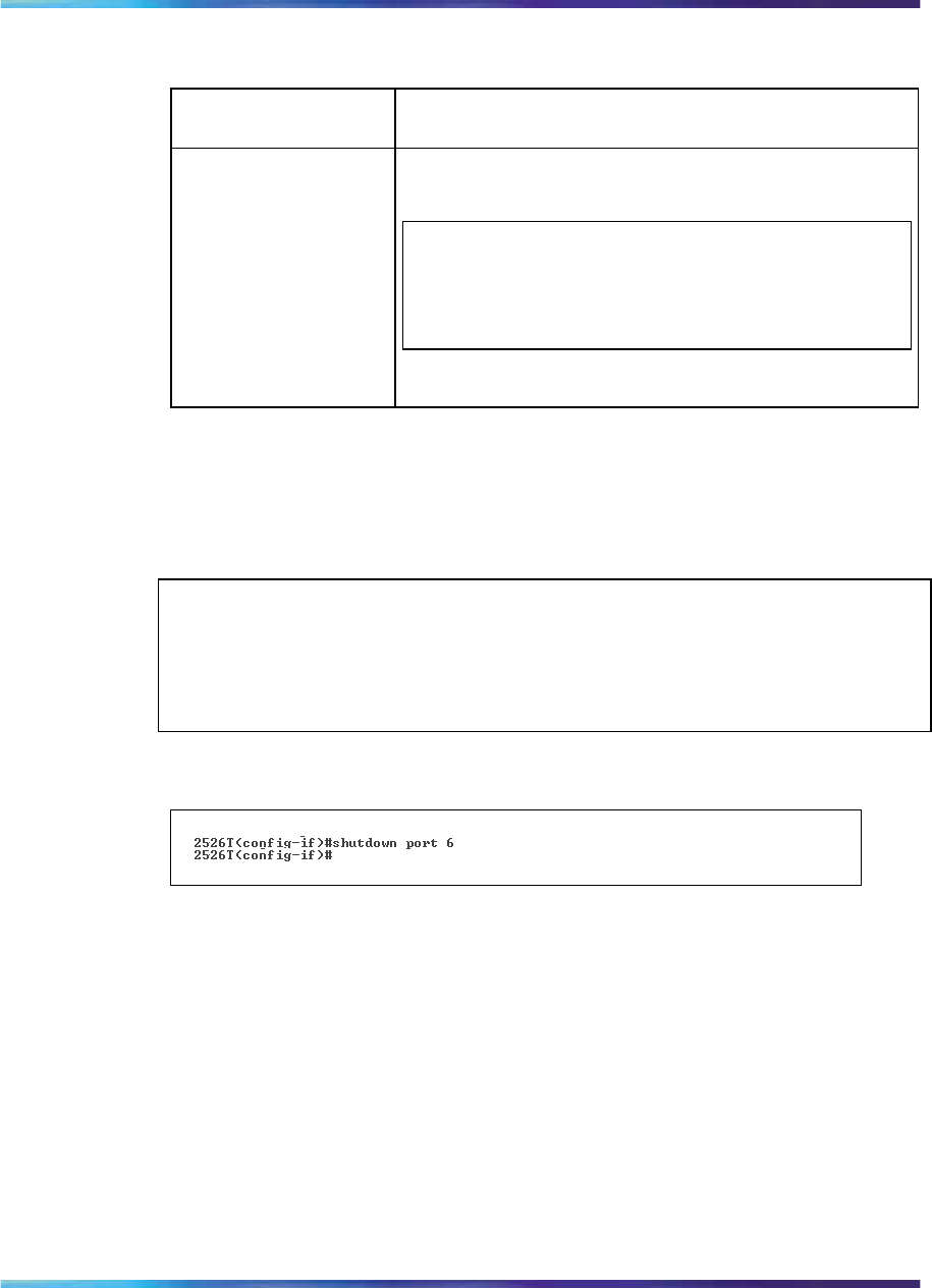
234 Ethernet port management using the CLI
Table 91
shutdown port command parameters and variables
Parameters and
variables Description
line <portlist> Specifies the port numbers to shut down or disable.
Enter the port numbers you want to disable.
ATTENTION
If you omit this parameter, the system uses the port
number you specified in the interface command.
The shutdown [line <portlist>] command is executed in the
Interface Configuration command mode.
Figure 87 "shutdown port command output" (page 234) displays sample
output from the shutdown [line <portlist>] command.
ATTENTION
You can disable switch ports that are trunk members, if you choose to disable
them one by one. If you choose to disable all ports of the unit or stack, the
changes can have effect on the ports belonging to MLTs.
Figure 87
shutdown port command output
no shutdown command
The no shutdown command enables the port. The syntax for the no
shutdown command is:
no shutdown [line <portlist>]
The no shutdown command is executed in the Interface Configuration
command mode.
Table 92 "no shutdown command parameters and variables" (page
235) describes the parameters and variables for the no shutdown command.
Nortel Ethernet Routing Switch 2500 Series
Overview — System Configuration
NN47215-500 (323162-B) 02.02 Standard
4.1 19 November 2007
Copyright © 2007, Nortel Networks
.

Naming ports 235
Table 92
no shutdown command parameters and variables
Parameters and
variables Description
line <portlist> Specifies the port numbers to enable. Enter the port
numbers you want to disable.
ATTENTION
If you omit this parameter, the system uses the port
number you specified in the interface command.
Naming ports
You can name a port using the CLI. This section covers the following
commands:
•"name command" (page 235)
•"no name command" (page 236)
•"default name command" (page 236)
name command
The name command lets you name ports or to change the name. The
syntax for the name command is:
name [port <portlist>] <LINE>
The name command is executed in the Interface Configuration command
mode.
Table 93 "name command parameters and variables" (page 235) describes
the parameters and variables for the name command.
Table 93
name command parameters and variables
Parameters and
variables Description
port <portlist> Specifies the port numbers to name.
Nortel Ethernet Routing Switch 2500 Series
Overview — System Configuration
NN47215-500 (323162-B) 02.02 Standard
4.1 19 November 2007
Copyright © 2007, Nortel Networks
.

236 Ethernet port management using the CLI
Parameters and
variables Description
ATTENTION
If you omit this parameter, the system uses the port
number you specified in the interface command.
<LINE> Enter up to 26 alphanumeric characters.
no name command
The no name command clears the port names; it resets the field to an
empty string. The syntax for the no name command is:
no name [port <portlist>]
The no name command is executed in the Interface Configuration
command mode.
Table 94 "no name command parameters and variables" (page
236) describes the parameters and variables for the no name command.
Table 94
no name command parameters and variables
Parameters and
variables Description
port <portlist> Specifies the port numbers to clear of names.
ATTENTION
If you omit this parameter, the system uses the port
number you specified in the interface command.
default name command
The default name command clears the port names; it resets the field to
an empty string. The syntax for the default name command is:
default name [port <portlist>]
The default name command is executed in the Interface Configuration
command mode.
Table 95 "default name command parameters and variables" (page
237) describes the parameters and variables for the default name command.
Nortel Ethernet Routing Switch 2500 Series
Overview — System Configuration
NN47215-500 (323162-B) 02.02 Standard
4.1 19 November 2007
Copyright © 2007, Nortel Networks
.

Setting port speed 237
Table 95
default name command parameters and variables
Parameters and
variables Description
port <portlist> Specifies the port numbers to clear of names.
ATTENTION
If you omit this parameter, the system uses the port
number you specified in the interface command.
Setting port speed
You can set the speed and duplex mode for a port. This section covers:
•"speed command" (page 237)
•"default speed command" (page 238)
•"duplex command" (page 239)
•"Enabling or disabling a port" (page 233)
speed command
The speed command sets the speed of the port. The syntax for the speed
command is:
speed [port <portlist>] {10|100|1000|auto}
The speed command is executed in the Interface Configuration command
mode.
Table 96 "speed command parameters and variables" (page 237) describes
the parameters and variables for the speed command.
Table 96
speed command parameters and variables
Parameters and
variables Description
port <portlist> Specifies the port numbers to configure the speed.
Enter the port numbers you want to configure.
Nortel Ethernet Routing Switch 2500 Series
Overview — System Configuration
NN47215-500 (323162-B) 02.02 Standard
4.1 19 November 2007
Copyright © 2007, Nortel Networks
.

238 Ethernet port management using the CLI
Parameters and
variables Description
ATTENTION
If you omit this parameter, the system uses the port
number you specified in the interface command.
10|100|1000|auto Sets speed to:
•10—10 Mb/s
•100—100 Mb/s
•1000—1000 Mb/s or 1 GB/s
•auto—autonegotiation
ATTENTION
When you set the port speed for autonegotiation, ensure that the other side of
the link is also set for autonegotiation.
default speed command
The default speed command sets the speed of the port to the factory
default speed. The syntax for the default speed command is:
default speed [port <portlist>]
The default speed command is executed in the Interface Configuration
command mode.
Table 97 "default speed command parameters and variables" (page
238) describes the parameters and variables for the default speed
command.
Table 97
default speed command parameters and variables
Parameters and
variables Description
port <portlist> Specifies the port numbers to set the speed to factory
default. Enter the port numbers you want to set.
ATTENTION
If you omit this parameter, the system uses the port
number you specified in the interface command.
Nortel Ethernet Routing Switch 2500 Series
Overview — System Configuration
NN47215-500 (323162-B) 02.02 Standard
4.1 19 November 2007
Copyright © 2007, Nortel Networks
.

Setting port speed 239
duplex command
The duplex command specifies the duplex operation for a port. The syntax
for the duplex command is:
duplex [port <portlist>] {full|half|auto}
The duplex command is executed in the Interface Configuration command
mode.
Table 98 "duplex command parameters and variables" (page 239) describes
the parameters and variables for the duplex command.
Table 98
duplex command parameters and variables
Parameters and
variables Description
port <portlist> Specifies the port number to configure the duplex
mode. Enter the port number you want to configure,
or all to configure all ports simultaneously.
ATTENTION
If you omit this parameter, the system uses the port
number you specified in the interface command.
full|half|auto Sets duplex to:
•full—full-duplex mode
•half—half-duplex mode
•auto—autonegotiation
ATTENTION
When you set the duplex mode for autonegotiation, ensure that the other side of
the link is also set for autonegotiation.
default duplex command
The default duplex command sets the duplex operation for a port to
the factory default duplex value. The syntax for the default duplex
command is:
default duplex [port <portlist>]
The default duplex command is executed in the Interface Configuration
command mode.
Nortel Ethernet Routing Switch 2500 Series
Overview — System Configuration
NN47215-500 (323162-B) 02.02 Standard
4.1 19 November 2007
Copyright © 2007, Nortel Networks
.

240 Ethernet port management using the CLI
Table 99 "default duplex command parameters and variables" (page
240) describes the parameters and variables for the default duplex
command.
Table 99
default duplex command parameters and variables
Parameters and
variables Description
port <portlist> Specifies the port numbers to reset the duplex mode
to factory default values. Enter the port numbers
you want to configure, or all to configure all ports
simultaneously. The default value is autonegotiation.
ATTENTION
If you omit this parameter, the system uses the port
number you specified in the interface command.
Enabling flow control
If you use a Gigabit Ethernet with the Ethernet Routing Switch 2500 Series,
you control traffic on this port using the flowcontrol command. This
section covers the following commands:
•"flowcontrol command" (page 240)
•"no flowcontrol command" (page 241)
•"default flowcontrol command" (page 242)
flowcontrol command
The flowcontrol command is used only on Gigabit Ethernet ports
and controls the traffic rates during congestion. The syntax for the
flowcontrol command is:
flowcontrol [port <portlist>]
{asymmetric|symmetric|auto|disable}
The flowcontrol command is executed in the Interface Configuration
command mode.
Table 100 "flowcontrol command parameters and variables" (page
241) describes the parameters and variables for the flowcontrol command.
Nortel Ethernet Routing Switch 2500 Series
Overview — System Configuration
NN47215-500 (323162-B) 02.02 Standard
4.1 19 November 2007
Copyright © 2007, Nortel Networks
.

Enabling flow control 241
Table 100
flowcontrol command parameters and variables
Parameters and
variables Description
port <portlist> Specifies the port numbers to configure for flow
control.
ATTENTION
If you omit this parameter, the system uses the port
number you specified in the interface command.
asymmetric|
symmetric|
auto|disable
Sets the mode for flow control:
•asymmetric—enables the local port to perform flow
control on the remote port
•symmetric—enables the local port to perform flow
control
•auto—sets the port to automatically determine the
flow control mode (default)
•disable—disables flow control on the port
no flowcontrol command
The no flowcontrol command is used only on Gigabit Ethernet ports
and disables flow control. The syntax for the no flowcontrol command
is:
no flowcontrol [port <portlist>]
The no flowcontrol command is executed in the Interface Configuration
command mode.
Table 101 "no flowcontrol command parameters and variables" (page
242) describes the parameters and variables for the no flowcontrol
command.
Nortel Ethernet Routing Switch 2500 Series
Overview — System Configuration
NN47215-500 (323162-B) 02.02 Standard
4.1 19 November 2007
Copyright © 2007, Nortel Networks
.

242 Ethernet port management using the CLI
Table 101
no flowcontrol command parameters and variables
Parameters and
variables Description
port <portlist> Specifies the port numbers to disable flow control.
ATTENTION
If you omit this parameter, the system uses the port
number you specified in the interface command.
default flowcontrol command
The default flowcontrol command is used only on Gigabit Ethernet
ports and sets the flow control to auto, which automatically detects the flow
control. The syntax for the default flowcontrol command is:
default flowcontrol [port <portlist>]
The default flowcontrol command is executed in the Interface
Configuration command mode.
Table 102 "default flowconrtol command parameters and variables" (page
242) describes the parameters and variables for the default flowcontrol
command.
Table 102
default flowconrtol command parameters and variables
Parameters and
variables Description
port <portlist> Specifies the port numbers to default to auto flow
control.
ATTENTION
If you omit this parameter, the system uses the port
number you specified in the interface command.
Enabling rate-limiting
You can limit the percentage of multicast traffic, or broadcast traffic, or both
using the CLI.
Nortel Ethernet Routing Switch 2500 Series
Overview — System Configuration
NN47215-500 (323162-B) 02.02 Standard
4.1 19 November 2007
Copyright © 2007, Nortel Networks
.
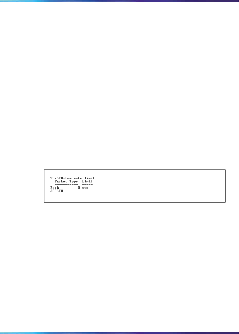
Enabling rate-limiting 243
This section contains information about the following:
•"show rate-limit command" (page 243)
•"rate-limit command" (page 243)
•"no rate-limit command" (page 244)
•"default rate-limit command" (page 244)
show rate-limit command
The show rate-limit command displays the rate-limiting settings and
statistics. The syntax for the show rate-limit command is:
show rate-limit
The show rate-limit command is executed in the Privileged EXEC
command mode.
The show rate-limit command has no parameters or variables.
Figure 88 "show rate-limit command output" (page 243) displays sample
output from the show rate-limit command.
Figure 88
show rate-limit command output
rate-limit command
The rate-limit command configures rate-limiting on the switch.
The syntax for the rate-limit command is:
rate-limit [multicast | broadcast | both] <0-262143>
The rate-limit command is executed in the Global Configuration
command mode.
Table 103 "rate-limit command parameters and variables" (page
244) describes the parameters and variables for the rate-limit command.
Nortel Ethernet Routing Switch 2500 Series
Overview — System Configuration
NN47215-500 (323162-B) 02.02 Standard
4.1 19 November 2007
Copyright © 2007, Nortel Networks
.

244 Ethernet port management using the CLI
Table 103
rate-limit command parameters and variables
Parameters and values Description
multicast |
broadcast | both
<0-262143>
Applies rate-limiting, in packets/second, to the
specified type of traffic.
•multicast—applies rate-limiting to multicast
packets
•broadcast—applies rate-limiting to broadcast
packets
•both—applies rate-limiting to both multicast and
broadcast packets
no rate-limit command
The no rate-limit command disables rate-limiting on the switch/stack.
The syntax for the no rate-limit command is:
no rate-limit
The no rate-limit command is executed in the Global Configuration
command mode.
default rate-limit command
The default rate-limit command restores the rate-limiting value
for the switch/stack to the default setting. The syntax for the default
rate-limit command is:
default rate-limit
The default rate-limit command is executed in the Global
Configuration command mode.
Enabling Custom Autonegotiation Advertisements (CANA)
You can control the capabilities that are advertised by the Ethernet
Routing Switch as part of the auto-negotiation process using the Custom
Autonegotiation Advertisements (CANA) feature. When autonegotiation is
disabled, the hardware is configured for a single (fixed) speed and duplex
value. When auto-negotiation is enabled, the advertisement made by
the switch is a constant value based upon all speed and duplex modes
supported by the hardware. When auto-negotiating, the switch selects the
highest common operating mode supported between it and its link partner.
This section covers:
•"show auto-negotiation-advertisements command" (page 245)
•"show auto-negotiation-capabilities command" (page 245)
Nortel Ethernet Routing Switch 2500 Series
Overview — System Configuration
NN47215-500 (323162-B) 02.02 Standard
4.1 19 November 2007
Copyright © 2007, Nortel Networks
.
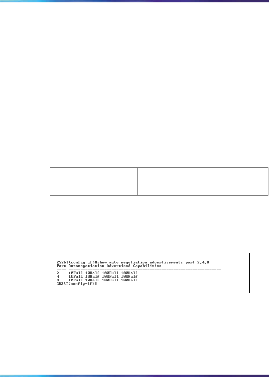
Enabling Custom Autonegotiation Advertisements (CANA) 245
•"auto-negotiation-advertisements command" (page 246)
•"no auto-negotiation-advertisements command" (page 247)
•"default auto-negotiation-advertisements command" (page 247)
show auto-negotiation-advertisements command
The show auto-negotiation-advertisements command displays
the current autonegotiation advertisements. The syntax for the show
auto-negotiation-advertisements command is:
show auto-negotiation-advertisements [port <portlist>]
The show auto-negotiation-advertisements command is executed
in the User Exec command mode.
Table 104 "show auto-negotiation-advertisements command"
(page 245) describes the parameters and variables for the show
auto-negotiation-advertisements command.
Table 104
show auto-negotiation-advertisements command
Parameters and values Description
port <portlist> Enter ports for which you want the current
autonegotiation advertisements displayed.
Figure 89 "show auto-negotiation-advertisements command output" (page
245) displays sample output from the show auto-negotiation-advertisements
command.
Figure 89
show auto-negotiation-advertisements command output
show auto-negotiation-capabilities command
The show auto-negotiation-capabilities command displays the
hardware advertisement capabilities for the switch. The syntax for the show
auto-negotiation-capabilities command is:
show auto-negotiation-capabilities [port <portlist>]
The show auto-negotiation-capabilities command is executed
in the User Exec command mode.
Nortel Ethernet Routing Switch 2500 Series
Overview — System Configuration
NN47215-500 (323162-B) 02.02 Standard
4.1 19 November 2007
Copyright © 2007, Nortel Networks
.
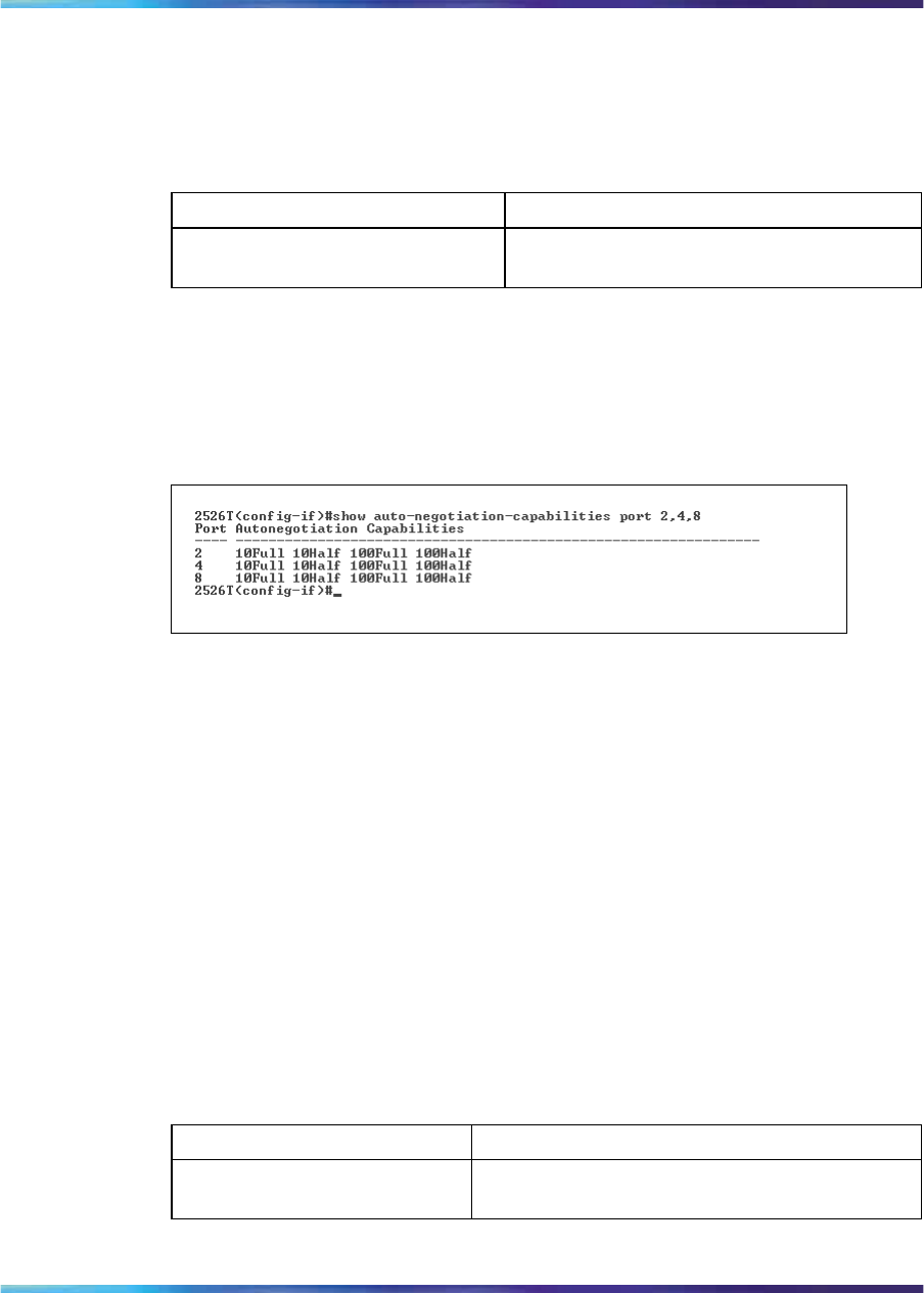
246 Ethernet port management using the CLI
Table 105 "show auto-negotiation-capabilities command" (page
246) describes the parameters and variables for the show
auto-negotiation-capabilities command.
Table 105
show auto-negotiation-capabilities command
Parameters and values Description
port <portlist> Enter ports for which you want the
autonegotiation capabilities displayed.
Figure 90 "show auto-negotiation-capabilities command output" (page
246) displays sample output from the show auto-negotiation-capabilities
command.
Figure 90
show auto-negotiation-capabilities command output
auto-negotiation-advertisements command
The auto-negotiation-advertisements command
configures advertisements for the switch. The syntax for the
auto-negotiation-advertisements command is:
auto-negotiation-advertisements [port <portlist>] [10-full]
[10-half] [100-full] [100-half] [1000-full]
[asymm-pause-frame] [pause-frame] [none]
The auto-negotiation-advertisements command is executed in the
Interface Configuration command mode.
Table 106 "auto-negotiation-advertisements command" (page 246) describes
the parameters and variables for the auto-negotiation-advertisements
command.
Table 106
auto-negotiation-advertisements command
Parameters and values Description
port <portlist> Enter ports for which you want to configure
advertisements.
Nortel Ethernet Routing Switch 2500 Series
Overview — System Configuration
NN47215-500 (323162-B) 02.02 Standard
4.1 19 November 2007
Copyright © 2007, Nortel Networks
.

Enabling Custom Autonegotiation Advertisements (CANA) 247
Parameters and values Description
[10-full] [10-half]
[100-full] [100-half]
[1000-full]
[asymm-pause-frame]
[pause-frame]
These are speed-duplex-pause settings. Any
combination of these settings is allowed, but
parameters must be given in the order shown.
none Do not advertise any settings during
auto-negotiation.
no auto-negotiation-advertisements command
The no auto-negotiation-advertisements command clears all
advertisements for the switch. This command is used for testing. The syntax
for the no auto-negotiation-advertisements command is:
no auto-negotiation-advertisements [port <portlist>]
ATTENTION
The use of this command affects traffic and brings down the link.
The no auto-negotiation-advertisements command is executed
in the Interface Configuration command mode.
Table 107 "no auto-negotiation-advertisements command"
(page 247) describes the parameters and variables for the no
auto-negotiation-advertisements command.
Table 107
no auto-negotiation-advertisements command
Parameters and values Description
port <portlist> Enter ports for which you want to clear all
advertisements.
default auto-negotiation-advertisements command
The default auto-negotiation-advertisements command
sets default advertisements for the switch. The syntax for the default
auto-negotiation-advertisements command is:
default auto-negotiation-advertisements [port <portlist>]
The default auto-negotiation-advertisements command is
executed in the interface configuration command mode.
Nortel Ethernet Routing Switch 2500 Series
Overview — System Configuration
NN47215-500 (323162-B) 02.02 Standard
4.1 19 November 2007
Copyright © 2007, Nortel Networks
.

248 Ethernet port management using the CLI
Table 108 "default auto-negotiation-advertisements command"
(page 248) describes the parameters and variables for the default
auto-negotiation-advertisements command.
Table 108
default auto-negotiation-advertisements command
Parameters and values Description
port <portlist> Enter ports for which you want to set default
advertisements.
This feature lets you customize the capabilities that you advertise. It also
lets you control the capabilities that are advertised by the Ethernet Routing
Switch as part of the auto-negotiation process.
Nortel Ethernet Routing Switch 2500 Series
Overview — System Configuration
NN47215-500 (323162-B) 02.02 Standard
4.1 19 November 2007
Copyright © 2007, Nortel Networks
.

249
Configuring the switch using Device
Manager
This section describes how you can use Device Manager to configure your
switch, manage SNTP, and display topology information.
The section includes information on the following topics:
•"Viewing Unit information" (page 249)
•"Viewing switch IP information" (page 253)
•"Editing the chassis configuration" (page 258)
•"Working with configuration files" (page 272)
•"Working with SNTP" (page 276)
•"Displaying topology information using Device Manager" (page 279)
Viewing Unit information
You can view unit information by using the Unit dialog box.
To open the Unit dialog box, use the following procedure:
Step Action
1Double-click on a single unit or select the units you want to edit.
2Do one of the following:
•From the shortcut menu, choose Edit.
•From the Device Manager main menu, choose Edit > Unit.
•On the toolbar, click Edit.
—End—
Nortel Ethernet Routing Switch 2500 Series
Overview — System Configuration
NN47215-500 (323162-B) 02.02 Standard
4.1 19 November 2007
Copyright © 2007, Nortel Networks
.
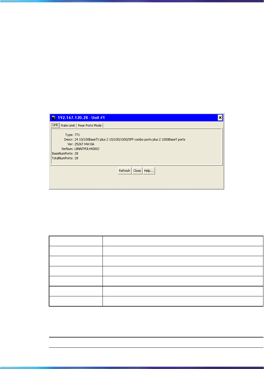
250 Configuring the switch using Device Manager
The following sections provide a description of the tabs in the Edit > Unit
dialog box and details about each item on the tab.
Unit tab
To open the Unit tab:
→From the Device Manager main menu, choose Edit > Unit.
The Unit dialog box appears with the Unit tab displayed.
Figure 91
Unit dialog box
The following table describes the Unit tab fields.
Table 109
Unit tab fields
Field Description
Type Specifies the type of switch.
Descr Description of switch.
Ver Specifies the hardware version number of the switch.
Sernum Specifies the serial number of the switch.
BaseNumPorts Specifies the base number of ports.
TotalNumPorts Specifies the total number of ports.
Rate Limit tab
To open the Rate Limit tab, use the following procedure:
Step Action
1From the Device Manager main menu, choose Edit > Unit.
Nortel Ethernet Routing Switch 2500 Series
Overview — System Configuration
NN47215-500 (323162-B) 02.02 Standard
4.1 19 November 2007
Copyright © 2007, Nortel Networks
.
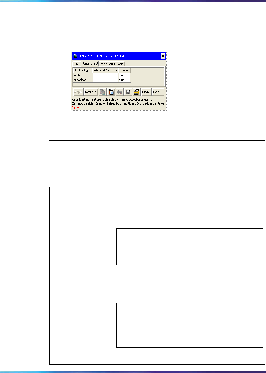
Viewing Unit information 251
The Unit dialog box appears with the Unit tab displayed.
2Click the Rate Limit tab.
The Rate limit tab appears.
Rate Limit tab
—End—
The following table describes the Rate Limit tab fields.
Table 110
Rate Limit tab fields
Field Description
Traffic Type Specifies the traffic type.
AllowedRatePps Allowed traffic rate packets/second. It is in the range
of 0-262143 (0-3FFFFh).
ATTENTION
Rate Limiting feature is disabled when
AllowedRatePps equals to 0.
Enable When Enable is set to True, the TrafficType can either
be multicast, broadcast, or both.
ATTENTION
You cannot set the Enabled field for both multicast
and broadcast TrafficeType to False at the same
time. This is illegal configuration.
Nortel Ethernet Routing Switch 2500 Series
Overview — System Configuration
NN47215-500 (323162-B) 02.02 Standard
4.1 19 November 2007
Copyright © 2007, Nortel Networks
.
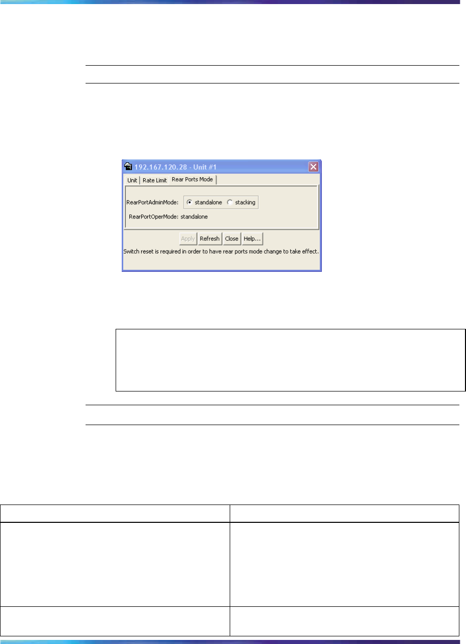
252 Configuring the switch using Device Manager
Rear Ports Mode tab Use the JDM to configure the operational mode
of the rear ports into standalone or Stacking Mode in the Ethernet Routing
Switch 2500 Series.
Step Action
1From the JDM menu, select Edit > Unit. The Unit dialog box opens
with the Unit tab displayed.
2Click the Rear Ports Mode tab. The Rear Ports Mode tab appears.
Rear Ports Mode tab
3Select Standalone or Stacking Mode from the radio buttons to
configure the operational mode of the rear ports.
ATTENTION
A switch reboot is required to the configured operational mode to take
effect.
—End—
The following table describes the Rear Port Mode tab items.
Table 111
Rear Ports Mode tab fields
Field Description
RearPortAdminMode •Standalone: Select this radio button to
configure the operational mode of the rear
ports to Standalone Mode.
•Stacking: Select this radio button to
configure the operational mode of the rear
ports to Stacking Mode.
RearPortOperMode Displays the configured operational mode of the
rear ports.
Nortel Ethernet Routing Switch 2500 Series
Overview — System Configuration
NN47215-500 (323162-B) 02.02 Standard
4.1 19 November 2007
Copyright © 2007, Nortel Networks
.
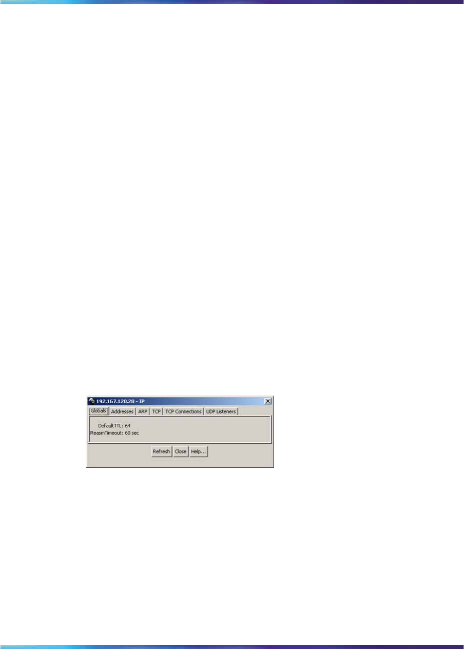
Viewing switch IP information 253
Viewing switch IP information
You can view the switch IP information using the IP dialog box.
To open the IP dialog box, use the following procedure:
→From the Device Manager main menu, choose Edit > IP.
The Edit IP dialog box appears with the Globals tab displayed.
The following sections provide a description of the tabs in the Edit > IP
dialog box and details about each item on the tab:
•"Globals tab" (page 253)
•"Addresses tab" (page 254)
•"ARP tab" (page 255)
•"TCP tab" (page 256)
•"TCP Connections tab" (page 257)
•"UDP Listeners tab" (page 257)
Globals tab
To open the Globals tab, use the following procedure:
→From the Device Manager main menu, choose Edit > IP.
The IP dialog box appears with the Globals tab displayed.
Figure 92
Globals tab
The following table describes the Globals tab fields.
Nortel Ethernet Routing Switch 2500 Series
Overview — System Configuration
NN47215-500 (323162-B) 02.02 Standard
4.1 19 November 2007
Copyright © 2007, Nortel Networks
.
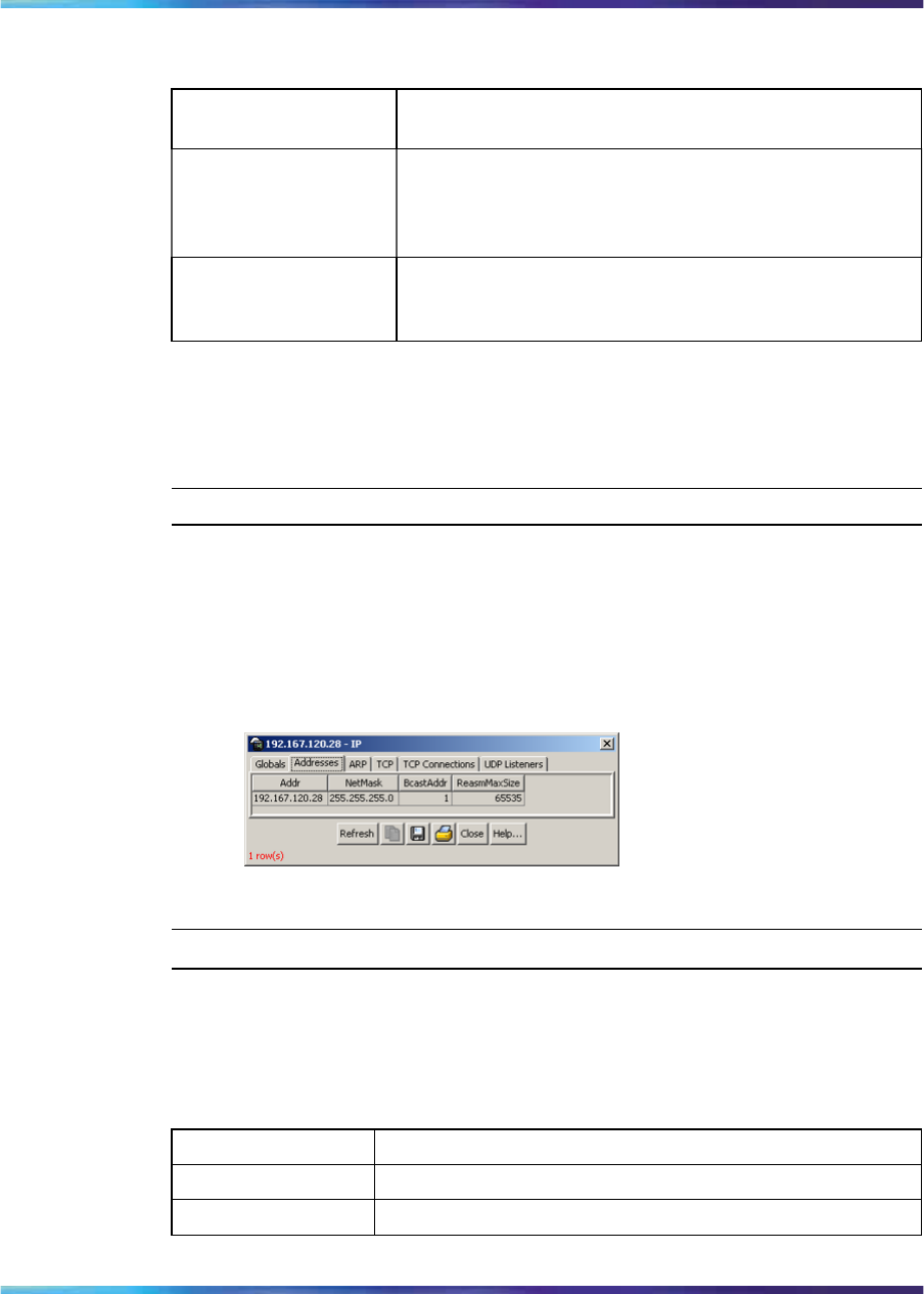
254 Configuring the switch using Device Manager
Table 112
Globals tab fields
Field and MIB
association Description
DefaultTTL Default value inserted into the Time-To-Live field of
the IP header of datagrams originated by the switch,
whenever a TTL value is not supplied by the transport
layer protocol. Default value is 64.
ReasmTimeout Maximum number of seconds that received fragments
are held while they are awaiting reassembly by the
switch. Default value is 60.
Addresses tab
The Addresses tab shows the IP address information for the device.
To open the Addresses tab, use the following procedure:
Step Action
1From the Device Manager main menu, choose Edit > IP.
The IP dialog box appears with the Globals tab displayed.
2Click the Addresses tab.
The Addresses tab appears.
Edit IP dialog box IP Address tab
—End—
The following table describes the Address tab fields.
Table 113
Addresses tab fields
Field Description
Addr The device IP address.
NetMask The subnet mask address.
Nortel Ethernet Routing Switch 2500 Series
Overview — System Configuration
NN47215-500 (323162-B) 02.02 Standard
4.1 19 November 2007
Copyright © 2007, Nortel Networks
.
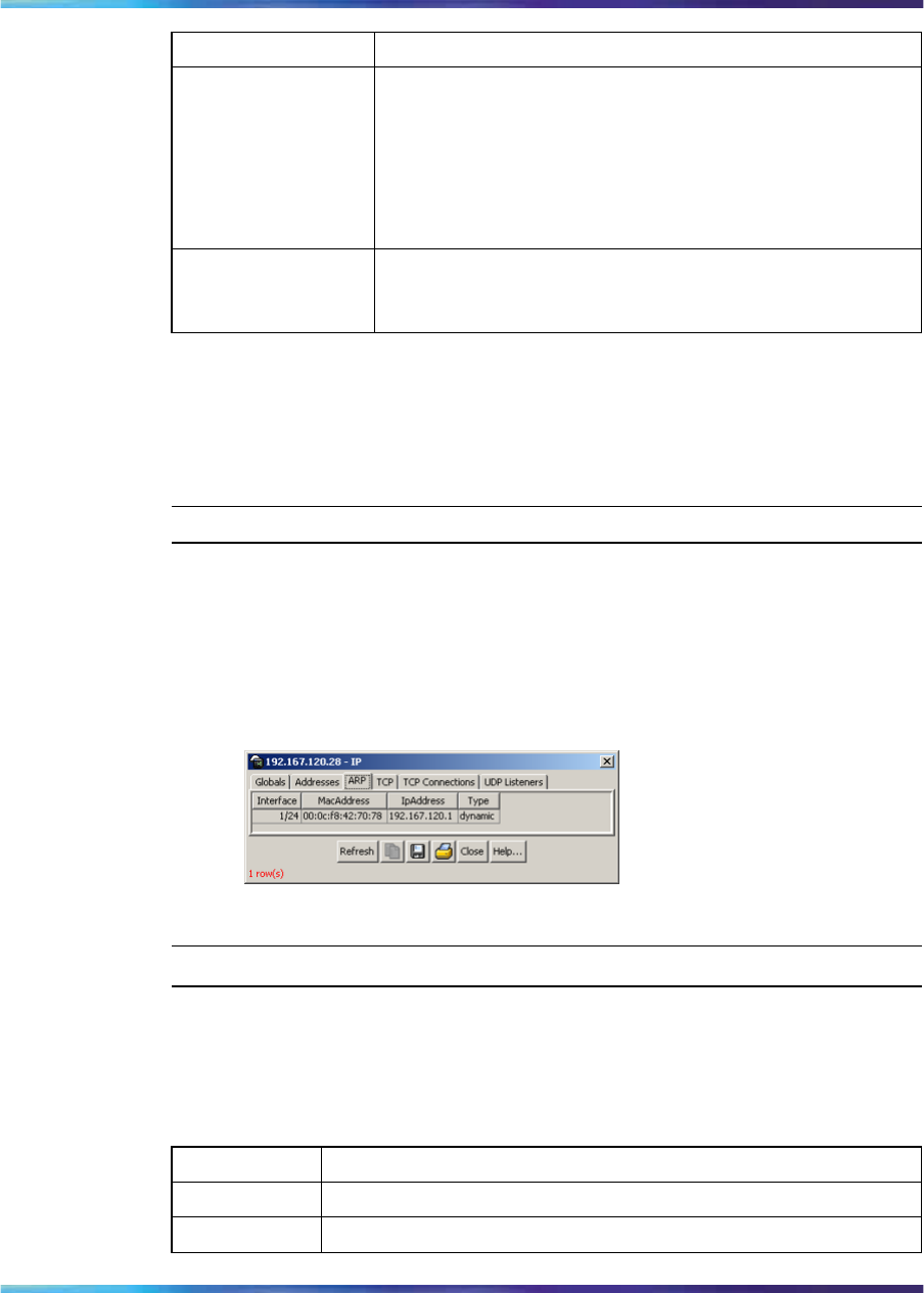
Viewing switch IP information 255
Field Description
BcastAddr The value of the least-significant bit in the IP broadcast
address used for sending datagrams on the (logical)
interface associated with the IP address of this entry. For
example, when the Internet standard all-ones broadcast
address is used, the value is 1. This value applies to both
the subnet and network broadcasts addresses used by the
entity on this (logical) interface.
ReasmMaxSize The size of the largest IP datagram that this entity can
reassemble from incoming IP fragmented datagrams
received on this interface.
ARP tab
The ARP (Address Resolution Protocol) tab shows the MAC addresses and
the associated IP addresses for the switch.
To open the ARP tab, use the following procedure:
Step Action
1From the Device Manager main menu, choose Edit > IP.
The IP dialog box appears with the Globals tab displayed.
2Click the ARP tab.
The ARP tab appears.
Edit IP dialog box ARP tab
—End—
The following table describes the ARP tab fields.
Table 114
ARP tab fields
Field Description
Interface The unit and port number.
MacAddress The unique hardware address of the device.
Nortel Ethernet Routing Switch 2500 Series
Overview — System Configuration
NN47215-500 (323162-B) 02.02 Standard
4.1 19 November 2007
Copyright © 2007, Nortel Networks
.
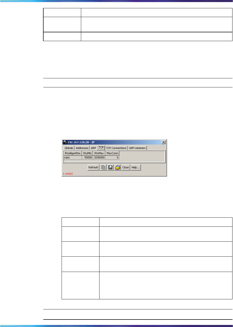
256 Configuring the switch using Device Manager
Field Description
IpAddress The Internet Protocol address of the device used to represent a
point of attachment in a TCP/IP internetwork.
Type The type of mapping.
TCP tab
The TCP tab displays TCP information for the switch.
To open the TCP tab, use the following procedure:
Step Action
1From the Device Manager main menu, choose Edit > IP.
The IP dialog box appears with the Globals tab displayed.
2Click the TCP tab.
The TCP tab appears.
TCP tab
The following table describes the TCP tab fields.
Table 115
TCP tab fields
Field Description
RtoAlgorithm The algorithm used to determine the timeout value used
for retransmitting unacknowledged octets.
RtoMin The minimum value permitted by a TCP implementation
for the retransmission timeout, measured in milliseconds.
RtoMax The maximum value permitted by a TCP implementation
for the retransmission timeout, measured in milliseconds.
MaxConn The limit on the total number of TCP connections that
the entity can support. In entities where the maximum
number of connections is dynamic, this object contains
the value -1.
—End—
Nortel Ethernet Routing Switch 2500 Series
Overview — System Configuration
NN47215-500 (323162-B) 02.02 Standard
4.1 19 November 2007
Copyright © 2007, Nortel Networks
.
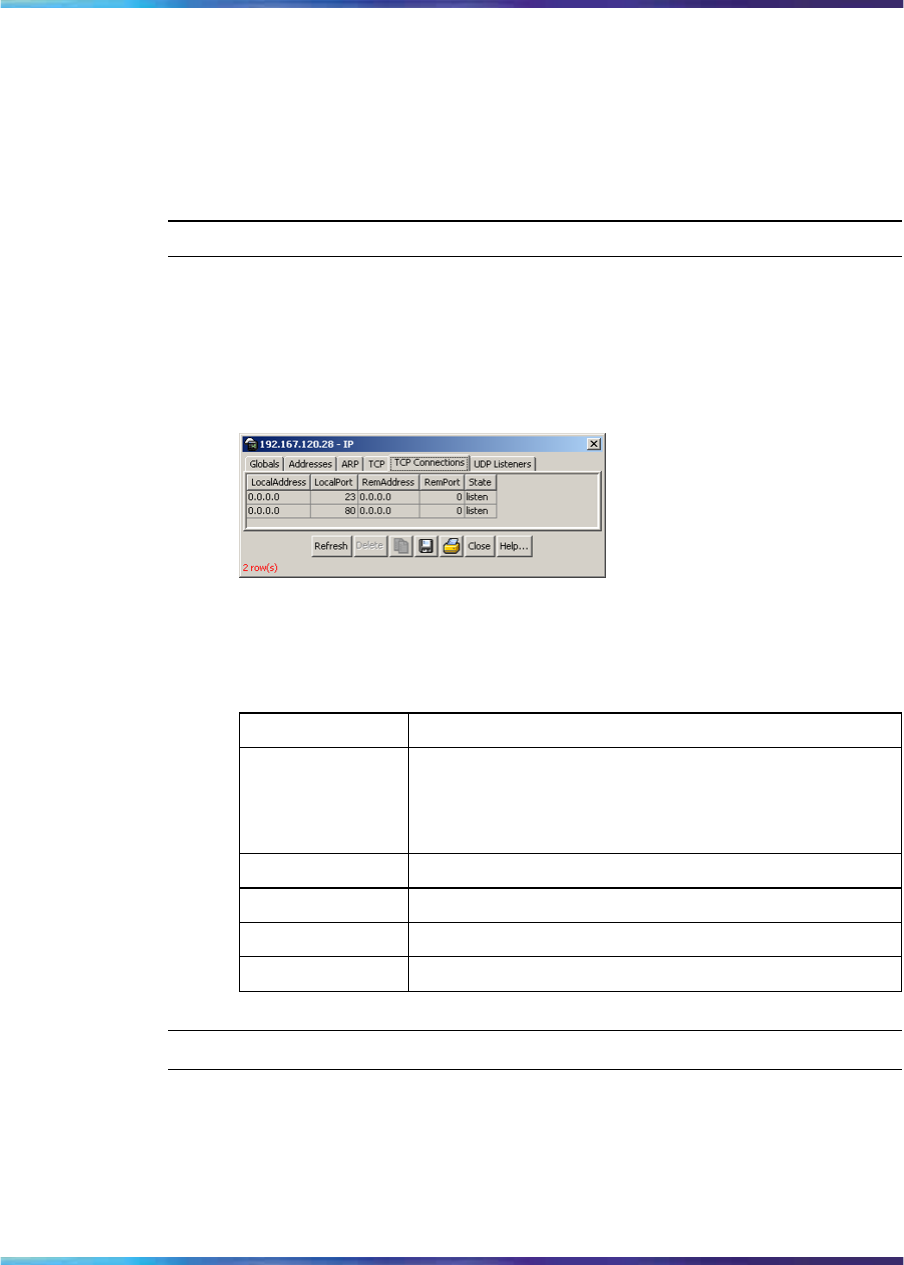
Viewing switch IP information 257
TCP Connections tab
The TCP Connections tab displays information on the current TCP
connections the switch maintains.
To open the TCP Connections tab, use the following procedure:
Step Action
1From the Device Manager main menu, choose Edit > IP.
The IP dialog box appears with the Globals tab displayed.
2Click the TCP Connections tab.
The TCP Connections tab appears.
The following table describes the TCP Connections tab fields.
TCP Connections tab fields
Field Description
LocalAddress The local IP address for this TCP connection. In the
case of a connection in the listen state, which is willing
to accept connections for any IP interface associated
with the node, the value 0.0.0.0 is used.
LocalPort The local port number for this TCP connection.
RemAddress The remote IP address for this TCP connection.
RemPort The remote port number for this TCP connection.
State The state of this TCP connection.
—End—
UDP Listeners tab
The UDP Listeners tab displays information on the UDP listeners currently
maintained by the switch.
To open the UDP Listeners tab, use the following procedure:
Nortel Ethernet Routing Switch 2500 Series
Overview — System Configuration
NN47215-500 (323162-B) 02.02 Standard
4.1 19 November 2007
Copyright © 2007, Nortel Networks
.
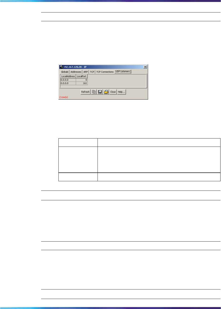
258 Configuring the switch using Device Manager
Step Action
1From the Device Manager main menu, choose Edit > IP.
The IP dialog box appears with the Globals tab displayed.
2Click the UDP Listeners tab.
The UDP Listeners tab appears.
The following table describes the UDP Listeners tab fields.
Table 116
UDP Listeners tab fields
Field Description
LocalAddress The local IP address for this UDP listener. In the case
of a UDP listener that accepts datagrams for any IP
interface associated with the node, the value 0.0.0.0
is used.
LocalPort The local port number for this UDP listener.
—End—
Editing the chassis configuration
You can edit a chassis configuration from the Edit Chassis dialog box.
To open the Chassis dialog box, use the following procedure:
Step Action
1Select the chassis.
2Do one of the following:
•From the Device Manager main menu, choose Edit > Chassis.
—End—
Nortel Ethernet Routing Switch 2500 Series
Overview — System Configuration
NN47215-500 (323162-B) 02.02 Standard
4.1 19 November 2007
Copyright © 2007, Nortel Networks
.
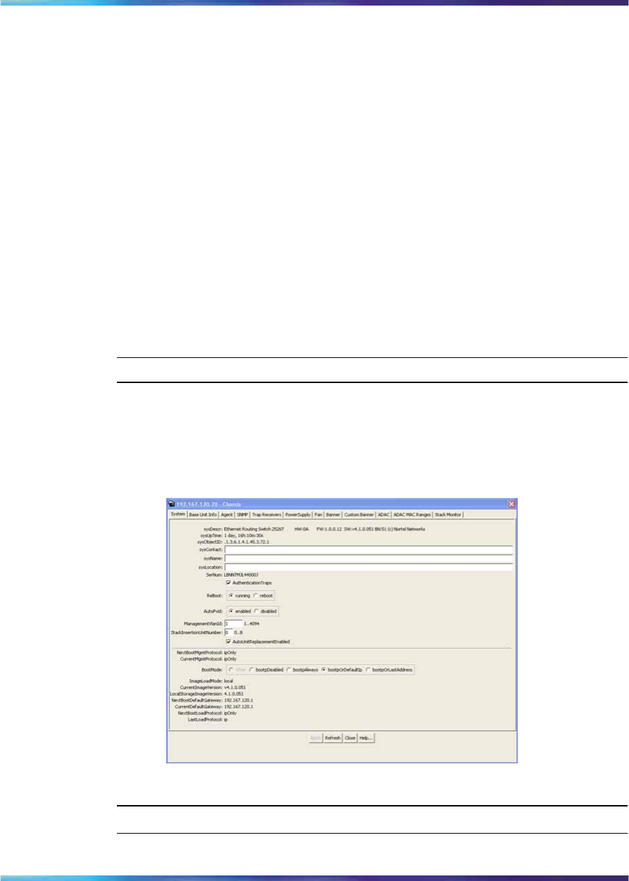
Editing the chassis configuration 259
The following sections provide a description of the tabs in the Edit > Chassis
dialog box and details about each field on the tab.
•"System tab" (page 259)
•"Base Unit Info tab" (page 261)
•"Agent tab" (page 265)
•"PowerSupply tab" (page 267)
•"Fan tab" (page 268)
•"Banner tab" (page 269)
•"Custom Banner tab" (page 271)
System tab
You can use the System tab to specify tracking information for a device,
device descriptions, and so on.
To open the System tab, use the following procedure:
Step Action
1Select the chassis.
2From the shortcut menu, choose Edit > Chassis.
The Chassis dialog box appears with the System tab displayed.
Edit Chassis dialog box System tab
—End—
Nortel Ethernet Routing Switch 2500 Series
Overview — System Configuration
NN47215-500 (323162-B) 02.02 Standard
4.1 19 November 2007
Copyright © 2007, Nortel Networks
.
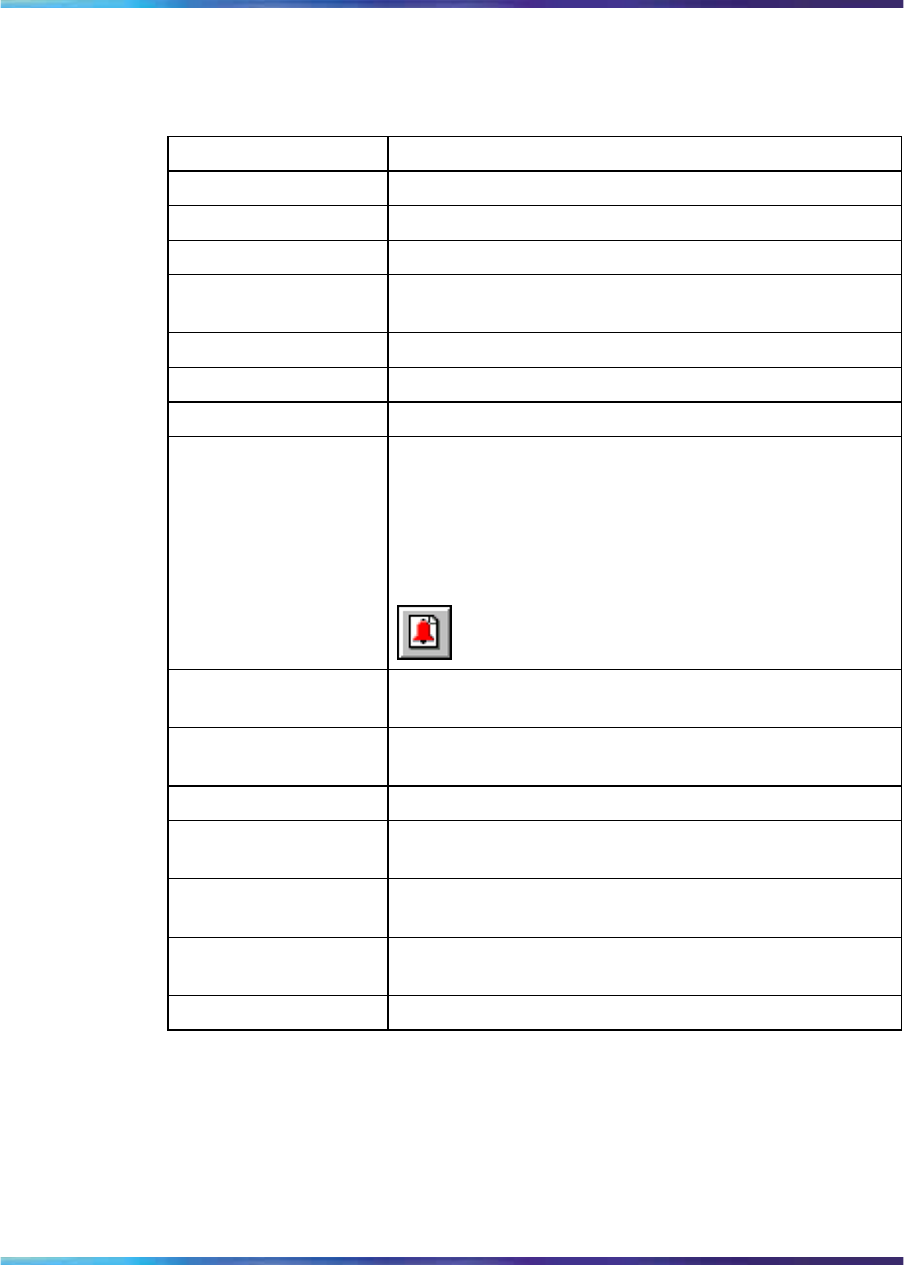
260 Configuring the switch using Device Manager
The following table describes the System tab fields.
Table 117
System tab fields
Field Description
sysDescr The assigned system description.
sysUpTime The time since the system was last booted.
sysObjectID The unique sysObjectID (OID) assigned to the device.
sysContact Type the contact information (in this case, an e-mail
address) for the system administrator.
sysName Type the name of this device.
sysLocation Type the physical location of this device.
SerNum The switch serial number.
AuthenticationTraps Click to enable or disable. When you enable, SNMP
traps are sent to trap receivers for all SNMP access
authentication. When you disable, no traps are received.
To view traps, click the Trap toolbar button.
ReBoot By default, the switch is in the Running mode. The
reboot command initiates a hardware reset.
AutoPVID Click to enable or disable. When you enable, AutoPVID
is activated. When you disable, AutoPVID is inactivated.
ManagementVlanId The current management VLAN ID.
StackInsertionUnitNu
mber This field specifies the unit number to be assigned to the
next unit that joins the stack, when in stack mode.
AutoUnitReplacement
Enabled Click to enable or disable the auto-unit-replacement
feature.
NextBootMgmt
Protocol The transport protocol(s) to use after the next boot of
the agent.
CurrentMgmtProtocol The current transport protocol(s) that the agent supports.
Nortel Ethernet Routing Switch 2500 Series
Overview — System Configuration
NN47215-500 (323162-B) 02.02 Standard
4.1 19 November 2007
Copyright © 2007, Nortel Networks
.

Editing the chassis configuration 261
Field Description
BootMode This setting determines how the management interface
of the switch can be assigned an IP address, the next
time the switch boots. The four BootMode options are:
•bootpDisabled - use the IP address contained in the
configuration file.
•bootpAlways - always attempt to get an IP address
from the network.
•bootpOrDefaultIP - attempt to get an IP address
from the network only when one is not contained
in the configuration file.
•bootpOrLastAddress - attempt to get an IP address
from the network and if that fails use the IP address
that was in use on this switch before the last reboot.
ImageLoadMode The source from which the agent image is loaded at
the next boot.
CurrentImageVersion The version number of the agent image that is currently
used on the switch.
LocalStorageImage
Version The version number of the agent image that is stored in
flash memory on the switch.
NextBootDefault
Gateway The IP address of the default gateway for the agent to
use after the next time the switch is booted.
CurrentDefault
Gateway The IP address of the default gateway that is currently
in use.
NextBootLoad
Protocol The transport protocol to be used by the agent to load
the configuration information and the image at the next
boot.
LastLoadProtocol The transport protocol last used to load the image and
configuration information on the switch.
Base Unit Info tab
The Base Unit Info tab provides read-only information about the operating
status of the hardware and whether or not the default factory settings are
being used.
To open the Base Unit Info tab, use the following procedure:
Step Action
1Select the chassis.
2From the shortcut menu, choose Edit > Chassis.
Nortel Ethernet Routing Switch 2500 Series
Overview — System Configuration
NN47215-500 (323162-B) 02.02 Standard
4.1 19 November 2007
Copyright © 2007, Nortel Networks
.
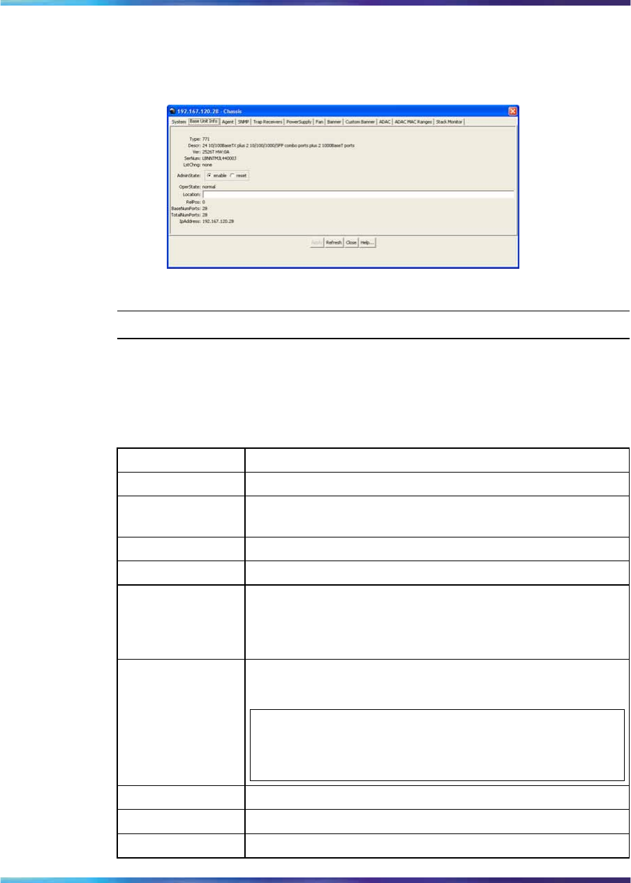
262 Configuring the switch using Device Manager
The Chassis dialog box appears with the System tab displayed.
3Click the Base Unit Info tab.
The Base Unit Info tab appears.
—End—
The following table describes the Base Unit Info tab fields.
Table 118
Base Unit Info tab fields
Field Description
Type The switch type.
Descr A description of the switch hardware, including number of
ports and transmission speed.
Ver The switch hardware version number.
SerNum The switch serial number.
LstChng The value of sysUpTime at the time the interface entered
its current operational state. If the current state was
entered prior to the last reinitialization of the local network
management subsystem, the value is zero.
AdminState Administrative state of the switch. Select either enable
or reset.
ATTENTION
In a stack configuration, Reset only resets the base unit.
OperState The operational state of the switch.
Location Type the physical location of the switch.
RelPos The relative position of the switch.
Nortel Ethernet Routing Switch 2500 Series
Overview — System Configuration
NN47215-500 (323162-B) 02.02 Standard
4.1 19 November 2007
Copyright © 2007, Nortel Networks
.
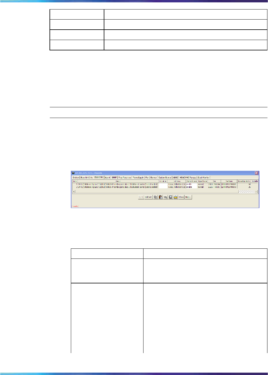
Editing the chassis configuration 263
Field Description
BaseNumPorts The number of base ports of the switch.
TotalNumPorts The number of ports of the switch.
IPAddress The base unit IP address.
Stack Info tab
Like the Base Unit Info tab, the Stack Info tab provides read-only
information about the operating status of the stacked switches and whether
or not the default factory settings are being used.
To open the Stack Info tab:
Step Action
1Open the Edit Chassis screen in the manner detailed at the
beginning of this section.
2Click the Stack Info tab. This tab is illustrated in "Edit Chassis
screen -- Stack Info tab" (page 263).
Edit Chassis screen—Stack Info tab
"Stack Info tab fields" (page 263) describes the Stack Info tab fields.
Stack Info tab fields
Field Description
Descr A description of the component or
subcomponent. If not available, the value is
a zero length string.
Location The geographic location of a component
in a system modeled as a chassis,
but possibly physically implemented
with geographically separate devices
connected together to exchange
management information. Chassis
modeled in this manner are sometimes
referred to as virtual chassis. An example
value is: 4th flr wiring closet in blg A.
Nortel Ethernet Routing Switch 2500 Series
Overview — System Configuration
NN47215-500 (323162-B) 02.02 Standard
4.1 19 November 2007
Copyright © 2007, Nortel Networks
.

264 Configuring the switch using Device Manager
Field Description
ATTENTION
1. This field is applicable only to
components that can be found in
either the Board or Unit groups. If the
information is unavailable, for example,
the chassis is not modeling a virtual
chassis or component is not in Board or
Unit group, the value is a zero length
string.
2. If this field is applicable and is not
assigned a value through a SNMP
SET PDU when the row is created, the
value defaults to the value of the object
s5ChasComSerNum.
LstChng The value of sysUpTime when it was
detected that the component/sub-component
was added to the chassis. If this action has
not occurred since the cold/warm start of the
agent, then the value is zero.
AdminState The state of the component or subcomponent.
The values that are read-only are:
•other – currently in some other state
•notAvail – actual value is not available
The possible values that can be read and
written are:
•disable—disables operation
•enable—enables operation
•reset—resets component
•test—starts self test of component,
with the result to be normal, warning,
nonFatalErr, or fatalErr in object
s5ChasComOperState The allowable
(and meaningful) values are determined
by the component type.
Nortel Ethernet Routing Switch 2500 Series
Overview — System Configuration
NN47215-500 (323162-B) 02.02 Standard
4.1 19 November 2007
Copyright © 2007, Nortel Networks
.

Editing the chassis configuration 265
Field Description
OperState The current operational state of the
component. The possible values are:
•other--some other state
•notAvail--state not available
•removed--component removed
•disabled--operation disabled
•normal--normal operation
•resetInProg--reset in progress
•testing--doing a self test
•warning--operating at warning level
•nonFatalErr--operating at error level
•fatalErr--error stopped operation
The allowable (and meaningful) values are
determined by the component type.
Ver The version number of the component or
subcomponent. If not available, the value is
a zero length string.
SerNum The serial number of the component or
subcomponent. If not available, the value is
a zero length string.
BaseNumPorts The number of base ports of the component
or subcomponent.
TotalNumPorts The number of ports of the component or
subcomponent.
IpAddress The IP address of the component or
subcomponent.
—End—
Agent tab
The Agent tab provides read-only information about the addresses that the
agent software uses to identify the switch.
To open the Agent tab, use the following procedure:
Nortel Ethernet Routing Switch 2500 Series
Overview — System Configuration
NN47215-500 (323162-B) 02.02 Standard
4.1 19 November 2007
Copyright © 2007, Nortel Networks
.
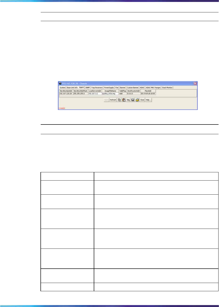
266 Configuring the switch using Device Manager
Step Action
1Select the chassis.
2From the shortcut menu, choose Edit > Chassis.
The Chassis dialog box appears with the System tab displayed.
3Click the Agent tab.
The Agent tab appears.
Edit Chassis dialog box Agent tab
—End—
The following table describes the Agent tab fields.
Table 119
Agent tab fields
Field Description
NextBootIpAddr The IP address to be used the next time the switch is
booted.
NextBootNetMask The subnet mask to be used the next time the switch
is booted.
LoadServerAddr The IP address of the load server for the configuration
file and/or the image file. If not used, then the value is
0.0.0.0.
ImageFileName Name of the image file(s) currently associated with the
interface. When the object is not used, the value is a
zero length string.
ValidFlag Indicates if the configuration and/or image file(s) were
downloaded from this interface and if the file names
have not been changed.
BootRouterAddr The IP address of the boot router for the configuration
file and/or the image file.
MacAddr The MAC address of the switch.
Nortel Ethernet Routing Switch 2500 Series
Overview — System Configuration
NN47215-500 (323162-B) 02.02 Standard
4.1 19 November 2007
Copyright © 2007, Nortel Networks
.
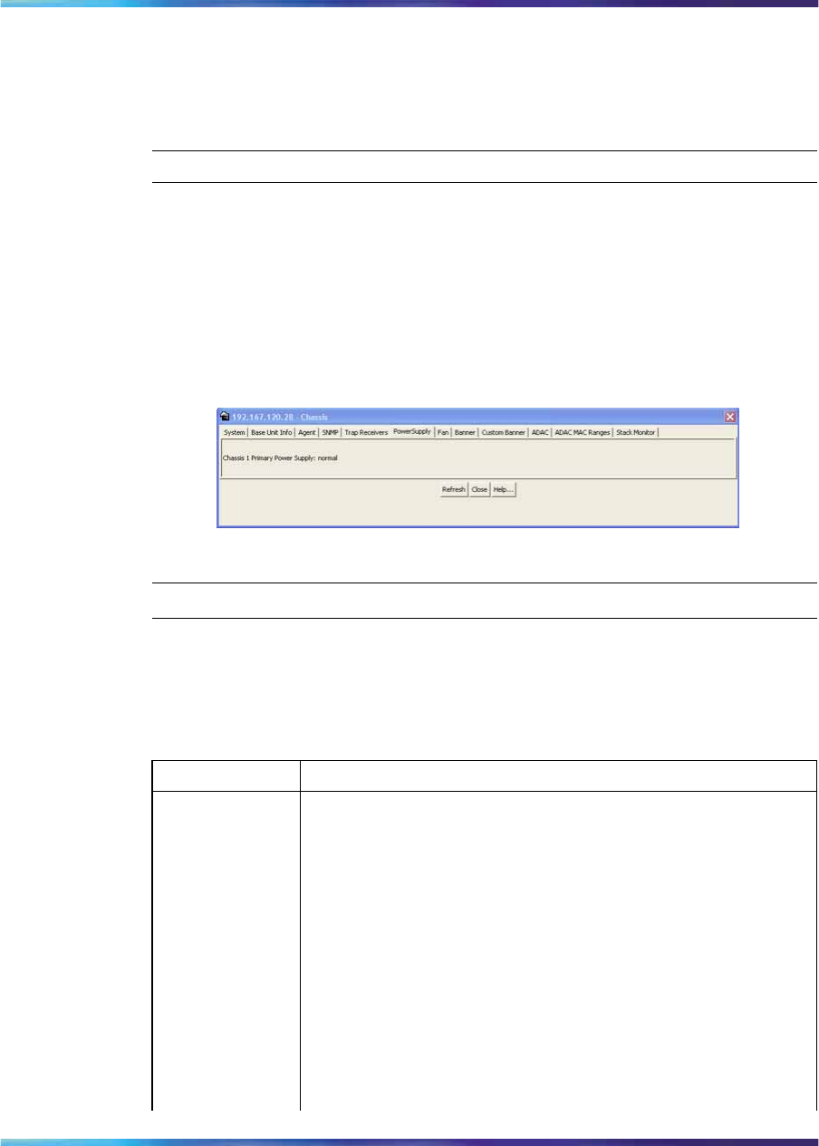
Editing the chassis configuration 267
PowerSupply tab
The PowerSupply tab provides read-only information about the operating
status of the switch power supplies.
To open the PowerSupply tab, use the following procedure:
Step Action
1Select the chassis.
2From the shortcut menu, choose Edit > Chassis.
The Chassis dialog box appears with the System tab displayed.
3Click the PowerSupply tab.
The PowerSupply tab appears.
Edit Chassis dialog box PowerSupply tab
—End—
The following table describes the PowerSupply tab fields.
Table 120
Power Supply tab fields
Field Description
Chassis
Primary
Power Supply
The operational state of the power supply. Possible values
include:
•other: Some other state.
•notAvail: State not available.
•removed: Component was removed.
•disabled: Operation disabled.
•normal: State is in normal operation.
•resetInProg: There is a reset in progress.
•testing: System is doing a self test.
•warning: System is operating at a warning level.
Nortel Ethernet Routing Switch 2500 Series
Overview — System Configuration
NN47215-500 (323162-B) 02.02 Standard
4.1 19 November 2007
Copyright © 2007, Nortel Networks
.
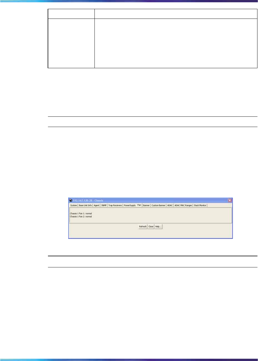
268 Configuring the switch using Device Manager
Field Description
•nonFatalErr: System is operating at error level.
•fatalErr: A fatal error stopped operation.
•notConfig: A module needs to be configured. The
allowable values are determined by the component type.
Fan tabThe Fan tab provides read-only information about the operating status of
the switch fans.
To open the Fan tab, use the following procedure:
Step Action
1Select the chassis.
2From the shortcut menu, choose Edit > Chassis.
The Chassis dialog box appears with the System tab displayed.
3Click the Fan tab.
The Fan tab appears.
Edit Chassis dialog box Fan tab
—End—
The following table describes the Fan tab fields.
Nortel Ethernet Routing Switch 2500 Series
Overview — System Configuration
NN47215-500 (323162-B) 02.02 Standard
4.1 19 November 2007
Copyright © 2007, Nortel Networks
.

Editing the chassis configuration 269
Table 121
Fan tab fields
Field Description
Chassis Fan The operational state of the fan. Values include:
•other: Some other state.
•notAvail: This state is not available.
•removed: Fan was removed.
•disabled: Fan is disabled.
•normal: Fan is operating in normal operation.
•resetInProg: A reset of the fan is in progress.
•testing: Fan is doing a self test.
•warning: Fan is operating at a warning level.
•nonFatalErr: Fan is operating at error level.
•fatalErr: An error stopped the fan operation
•notConfig: Fan needs to be configured. The allowable
values are determined by the component type.
Banner tab
The Banner tab lets you specify banner display in TELNET. You can specify
either the default banner or a custom banner.
To open the Banner tab, use the following procedure:
Step Action
1Select the chassis.
2From the main menu, choose Edit > Chassis.
The Chassis dialog box appears with the System tab displayed.
3Click the Banner tab.
The Banner tab appears.
Edit Chassis dialog box Banner tab
Nortel Ethernet Routing Switch 2500 Series
Overview — System Configuration
NN47215-500 (323162-B) 02.02 Standard
4.1 19 November 2007
Copyright © 2007, Nortel Networks
.
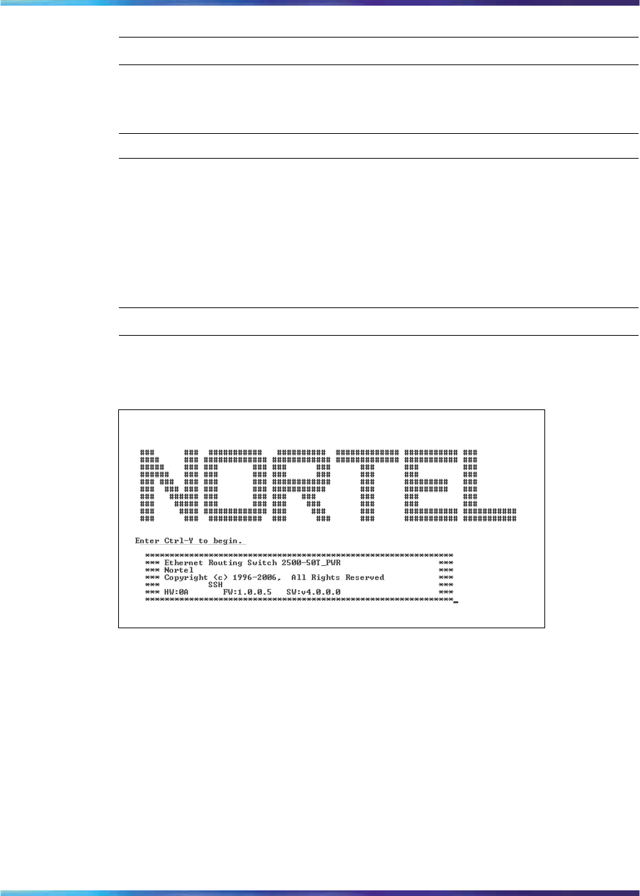
270 Configuring the switch using Device Manager
—End—
To set the default banner, use the following procedure:
Step Action
1In the Banner tab, click on the static radio button, and then click
Apply. This resets the banner in Telnet to the default banner.
To check that the default banner is set in Telnet:
2In the main menu, click on Device > Telnet.
The Telnet window appears with the default banner displayed.
—End—
Figure 93
Telnet window with default banner
To disable the banner:
→In the Banner tab, click on the disabled radio button, and then click Apply.
To check that the banner is disabled:
→In the main menu, click on Device > Telnet.
The Telnet window appears without the banner.
Nortel Ethernet Routing Switch 2500 Series
Overview — System Configuration
NN47215-500 (323162-B) 02.02 Standard
4.1 19 November 2007
Copyright © 2007, Nortel Networks
.
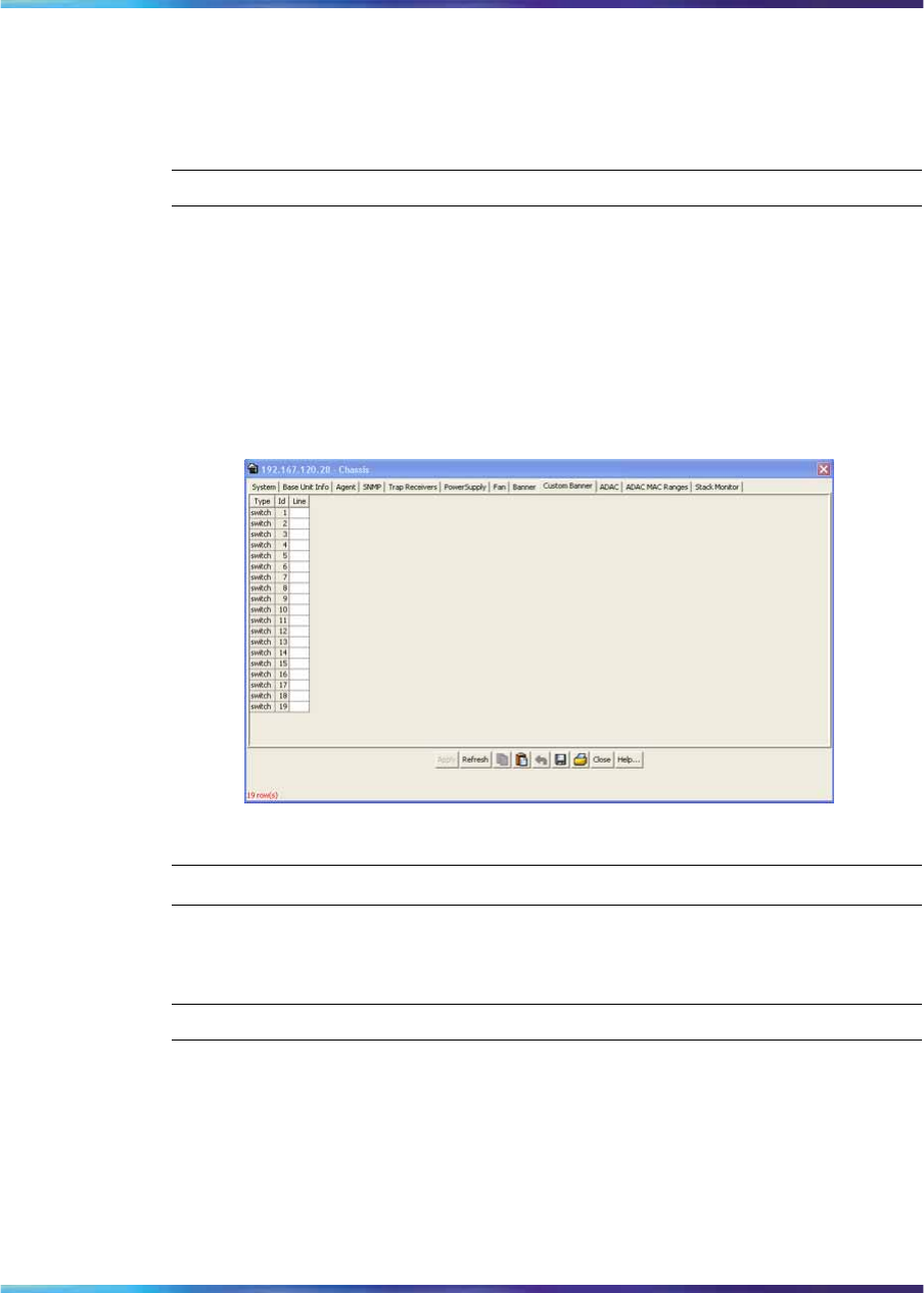
Editing the chassis configuration 271
Custom Banner tab
The Custom Banner tab lets you specify the display for a custom banner
in Telnet.
To open the Custom Banner tab, use the following procedure:
Step Action
1Select the chassis.
2From the main menu, choose Edit > Chassis.
The Chassis dialog box appears with the System tab displayed.
3Click the Custom Banner tab.
The Custom Banner tab appears.
Edit Chassis dialog box Custom Banner tab
—End—
To create a Custom Banner, use the following procedure:
Step Action
1In the Banner tab, click on the custom radio button, and then click
Apply.
2Click on the Custom Banner tab.
3In the Custom Banner tab, make the changes to the lines of the
banner that you want to create, and click Apply. The custom banner
is 19 lines high and can be up to 80 characters long.
Nortel Ethernet Routing Switch 2500 Series
Overview — System Configuration
NN47215-500 (323162-B) 02.02 Standard
4.1 19 November 2007
Copyright © 2007, Nortel Networks
.
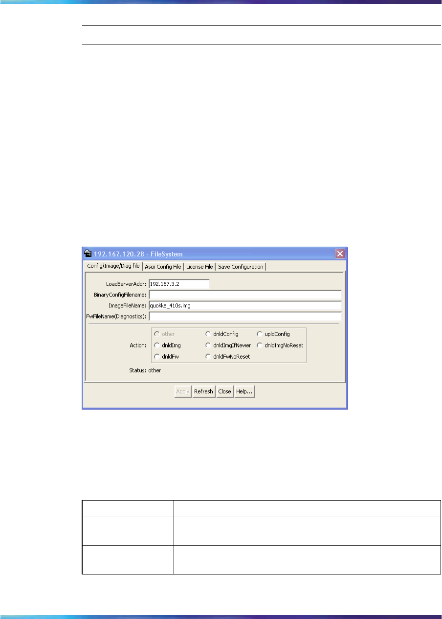
272 Configuring the switch using Device Manager
—End—
Working with configuration files
This chapter describes how you can view information and upload or
download the configuration and image files.
FileSystem dialog box
To open the Edit FileSystem dialog box, use the following procedure:
→From the Device Manager main menu, choose Edit > File System.
The FileSystem dialog box appears and displays the Config/Image/Diag
tab.
Figure 94
FileSystem - Config/Image/Diag File tab dialog box
Table 122 "FileSystem Config/Image/Diag file dialog box fields" (page
272) describes the FileSystem Config/Image/Diag file dialog box fields.
Table 122
FileSystem Config/Image/Diag file dialog box fields
Field Description
LoadServerAddr The IP address of the load server for the configuration file
and/or the image file. If not used, then the value is 0.0.0.0.
BinaryConfigFileN
ame Name of the configuration file currently associated with the
interface. When not used, the value is a zero length string.
Nortel Ethernet Routing Switch 2500 Series
Overview — System Configuration
NN47215-500 (323162-B) 02.02 Standard
4.1 19 November 2007
Copyright © 2007, Nortel Networks
.

Working with configuration files 273
Field Description
ImageFileName Name of the image file(s) currently associated with the
interface. When the object is not used, the value is a zero
length string.
FwFileName
(Diagnostics) Specifies the FWFileName.
Action •This object is used to download or upload a config file,
an image file or diag firmware file. In read operation, if
there is no action taken since the boot up, it returns with
a value of other. Otherwise, it returns the latest action.
•In a write operation, the values that can be written are:
dnldConfig
dnldImg
upIdConfig
dnldFw
dnldImgIfNewer
dnldImgNoReset
dnldFwNoReset
•The newly downloaded config, image or diag file cannot
take effect until the next boot cycle of the device.
Status This object is used to get the status of the latest action as
shown by s5AgInfoFileAction. The values that can be read
are:
•other—if no action taken since the boot up
•inProgress—the operation is in progress
•success—the operation succeeds
•fail—the operation failed
ASCII config file
To display the ASCII Config file tab, use the following procedure:
→In the File System dialog box, click on the ASCII Config File tab.
The ASCII Config File tab appears.
Nortel Ethernet Routing Switch 2500 Series
Overview — System Configuration
NN47215-500 (323162-B) 02.02 Standard
4.1 19 November 2007
Copyright © 2007, Nortel Networks
.
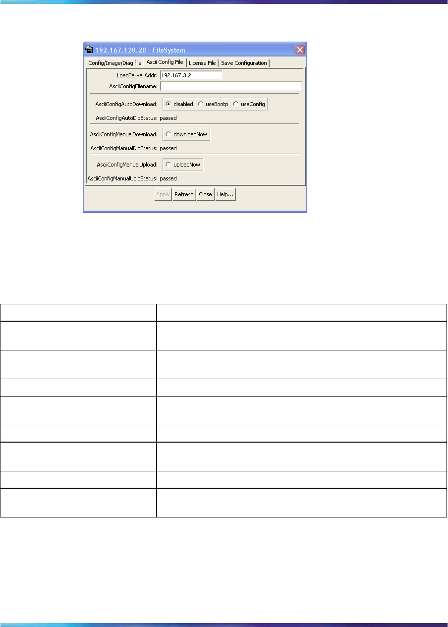
274 Configuring the switch using Device Manager
Figure 95
File system - ASCII Config File dialog box
Table 123 "ASCII Config File tab fields" (page 274) describes the ASCII
Config File tab fields.
Table 123
ASCII Config File tab fields
Field Description
LoadServerAddr The IP address of the load server for the ASCII configuration
file. If not used, then the value is 0.0.0.0.
ASCIIConfigFileName Name of the ASCII configuration file currently associated with
the interface. When not used, the value is a zero length string.
ASCIIConfigAutoDownload Specifies automatic ASCII configuration download.
ASCIIConfigAutodldStatus Specifies the current status of the ASCII configuration file
download.
ASCIIConfigManualDownload Specifies manual download of an ASCII configuration file.
ASCIIConfigManualdldStatus Specifies the current status of the manual download of an ASCII
configuration file.
ASCIIConfigManualUpload Specifies manual upload of an ASCII configuration file.
ASCIIConfigManualUpldStatus Specifies the current status of the manual upload of an ASCII
configuration file.
Save Configuration tab
You can use the Save Configuration tab to save the switch configuration
to NVRAM.
To open the Save Configuration tab, use the following procedure:
Nortel Ethernet Routing Switch 2500 Series
Overview — System Configuration
NN47215-500 (323162-B) 02.02 Standard
4.1 19 November 2007
Copyright © 2007, Nortel Networks
.
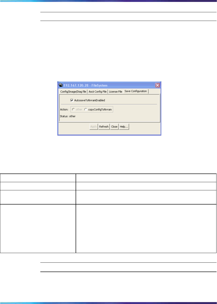
Working with configuration files 275
Step Action
1From the Device Manager main menu, choose Edit > File System.
The FileSystem dialog box appears with the Config/Image/Diag
tab displayed.
2Click the Save Configuration tab.
The Save Configuration tab appears.
Figure 96
Save Config tab
The following table describes the Save Configuration tab fields.
Table 124
Save Configuration tab fields
Field Description
AutoSavetoNvramEnabled Enables or disables autosave on the switch.
Action Select the copyConfigToNvram option to save the switch
configuration to NVRAM (and click Apply).
Status This field displays the status of the copyConfigToNvram action.
Possible values are:
•other—no action has been taken since switch boot
•inProgress—the operation is in progress
•success—the operation succeeded
•fail—the operation failed
—End—
Nortel Ethernet Routing Switch 2500 Series
Overview — System Configuration
NN47215-500 (323162-B) 02.02 Standard
4.1 19 November 2007
Copyright © 2007, Nortel Networks
.
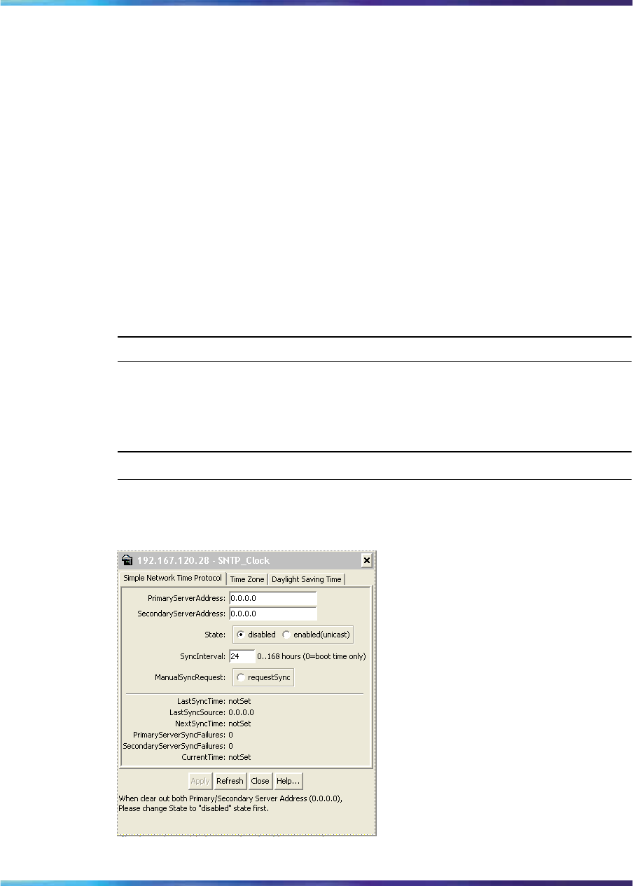
276 Configuring the switch using Device Manager
Working with SNTP
The Simple Network Time Protocol (SNTP) feature synchronizes the
Universal Coordinated Time (UTC) to an accuracy within 1 second. This
feature adheres to the IEEE RFC 2030 (MIB is the s5agent). With this
feature, the system can obtain the time from any RFC 2030-compliant
NTP/SNTP server.
The system retries connecting with the NTP server a maximum of 3 times,
with 5 minutes between each retry. If the connection fails after the 3
attempts, the system waits for the next synchronization time (the default is
24 hours) and begins the process again.
Configuring SNTP
The SNTP_Clock dialog box contains the parameters for configuring Simple
Network Time Protocol (SNTP).
To open the SNTP_clock dialog box, use the following procedure:
Step Action
1From the Main Menu, choose Edit > SNTP/Clock.
The SNTP_Clock dialog box appears. Select the Simple Network
Time Protocol tab.
—End—
Figure 97
SNTP_Clock dialog box
Nortel Ethernet Routing Switch 2500 Series
Overview — System Configuration
NN47215-500 (323162-B) 02.02 Standard
4.1 19 November 2007
Copyright © 2007, Nortel Networks
.

Working with SNTP 277
The following table describes the SNTP dialog box fields.
Table 125
SNTP_Clock dialog box fields
Field Description
Primary
Server
Address
The IP address of the primary SNTP server.
Secondary
Server
Address
The IP address of the secondary SNTP server.
State Controls whether the device uses the Simple Network Time
Protocol (SNTP), to synchronize the device’s clock to the
Coordinated Universal Time (UTC). If the value is disabled, the
device cannot synchronize its clock using SNTP.
If the value is unicast, the device synchronizes shortly after boot
time when network access becomes available, and periodically
thereafter.
SyncInterval Controls the frequency, in hours, that the device attempts to
synchronize with the NTP servers.
ManualSync
Request Specifies that the device to immediately attempt to synchronize
with the NTP servers.
LastSync
Time Specifies the Coordinated Universal Time (UTC) when the
device last synchronized with an NTP server.
LastSync
Source Specifies the IP source address of the NTP server with which
this device last synchronized
NextSync
Time Specifies the the Coordinated Universal Time (UTC) at which
the next synchronization is scheduled.
PrimaryServe
r Synch
Failures
Specifies the number of times the switch failed to synchronize
with the primary server address. However, synchronization with
the secondary server address may still occur.
Seconda
ryServer
SynchFailures
Specifies the number of times the switch failed to synchronize
with the secondary server address,
CurrentTime Specifies the switch’s current Coordinated Universal Time
(UTC).
ATTENTION
In order to clear out the PrimaryServerAddress and SecondaryServerAddress,
you must first set the State to disabled.
Nortel Ethernet Routing Switch 2500 Series
Overview — System Configuration
NN47215-500 (323162-B) 02.02 Standard
4.1 19 November 2007
Copyright © 2007, Nortel Networks
.
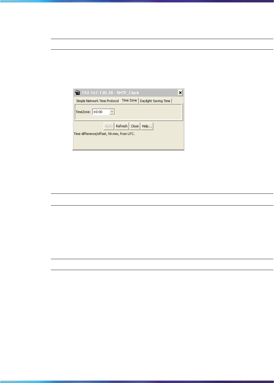
278 Configuring the switch using Device Manager
Configuring local time zone using the device manager
You can set the local time zone on the ERS 2500 using Time Zone tab. Use
the following procedure to set the local time zone.
Step Action
1From the Edit menu, choose SNTP/Clock. The SNTP_Clock dialog
box appears.
2Click theTime Zone tab. The Time Zone tab appears.
3Seect the time zone offset in the TimeZone box.
4Click Apply.
—End—
Configuring daylight savings time using the device manager
You can set daylight saving start and end time using the on the ERS 2500
using Daylight Saving Time tab. Use the following procedure to set daylight
saving start and end time.
Step Action
1From the Edit menu, choose SNTP/Clock. The SNTP_Clock dialog
box appears.
2Click the Daylight Saving Time tab. The Daylight Saving Time
tab appears.
Nortel Ethernet Routing Switch 2500 Series
Overview — System Configuration
NN47215-500 (323162-B) 02.02 Standard
4.1 19 November 2007
Copyright © 2007, Nortel Networks
.
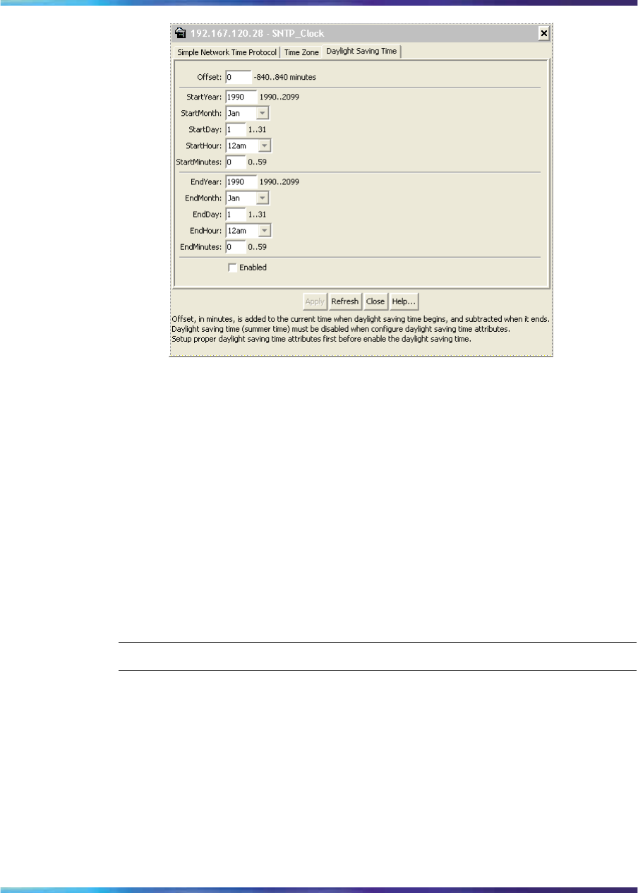
Displaying topology information using Device Manager 279
3Type the number of minutes to shift the clock in the Offset box.
4Select the StartYear,StartMonth,StartDate,StartHour, and type
the StartMinutes to define when to switch the clock to daylight
saving time.
5Select the EndYear,EndMonth,EndDate,EndHour, and type the
EndMinutes (if applicable) to define when to switch the clock back
to normal time. If you want to keep the same daylight saving time
changeover dates, you can set the EndYear to a year in the future.
6Click Enabled to enable daylight savings time.
7Click Apply.
—End—
Displaying topology information using Device Manager
This section describes diagnostic information available in Device Manager
on the following tabs:
•"Topology tab" (page 279)
•"Topology Table tab" (page 280)
Topology tab
To view topology information, use the following procedure:
Nortel Ethernet Routing Switch 2500 Series
Overview — System Configuration
NN47215-500 (323162-B) 02.02 Standard
4.1 19 November 2007
Copyright © 2007, Nortel Networks
.
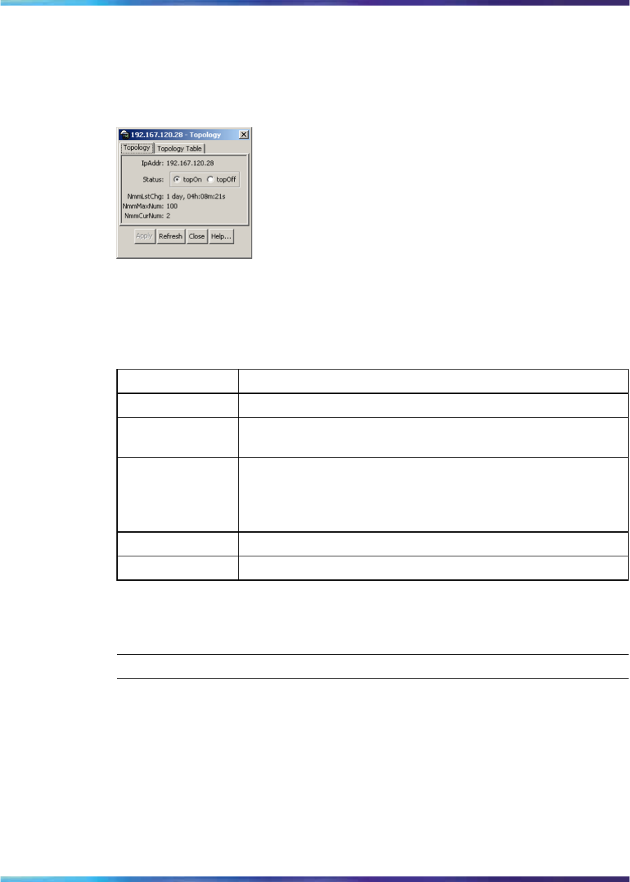
280 Configuring the switch using Device Manager
→From the Device Manager menu bar, select Edit > Diagnostics > Topology.
The Toplogy dialog box appears with the Topology tab displayed.
Figure 98
Diagnostics dialog box Topology tab
Table 126 "Topology tab fields" (page 280) describes the Topology tab fields.
Table 126
Topology tab fields
Field Description
IpAddr The IP address of the device.
Status Whether Nortel topology is on (topOn) or off (topOff) for the
device. The default value is topOn.
NmmLstChg The value of sysUpTime the last time an entry in the network
management MIB (NMM) topology table was added, deleted,
or modified. If the table has not changed since the last cold
or warm start of the agent.
NmmMaxNum The maximum number of entries in the NMM topology table.
NmmCurNum The current number of entries in the NMM topology table.
Topology Table tab
To view more topology information, use the following procedure:
Step Action
1From the Device Manager menu bar, choose Edit > Diagnostics >
Topology.
The Topology dialog box appears with the Topology tab displayed.
2Click the Topology Table tab.
The Topology Table tab appears.
Nortel Ethernet Routing Switch 2500 Series
Overview — System Configuration
NN47215-500 (323162-B) 02.02 Standard
4.1 19 November 2007
Copyright © 2007, Nortel Networks
.

Configuring LLDP using Device Manager 281
Figure 99
Diagnostics dialog box Topology Table tab
—End—
The following table describes the Topology Table tab fields.
Table 127
Topology Table tab fields
Field Description
Slot The slot number in the chassis in which the topology message
was received.
Port The port on which the topology message was received.
IpAddr The IP address of the sender of the topology message.
SegId The segment identifier of the segment from which the remote
agent sent the topology message. This value is extracted from
the message.
MacAddr The MAC address of the sender of the topology message.
ChassisType The chassis type of the device that sent the topology message.
BkplType The backplane type of the device that sent the topology
message.
LocalSeg Indicates if the sender of the topology message is on the same
Ethernet segment as the reporting agent.
CurState The current state of the sender of the topology message. The
choices are:
•topChanged—Topology information has recently changed.
•heartbeat—Topology information is unchanged.
•new—The sending agent is in a new state.
Configuring LLDP using Device Manager
Use the following tabs to configure LLDP properties for local and neighbor
systems:
•"LLDP Globals tab" (page 282)
Nortel Ethernet Routing Switch 2500 Series
Overview — System Configuration
NN47215-500 (323162-B) 02.02 Standard
4.1 19 November 2007
Copyright © 2007, Nortel Networks
.
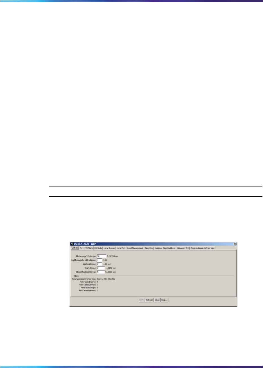
282 Configuring the switch using Device Manager
•"Port tab" (page 285)
•"TX Stats tab" (page 287)
•"Graphing LLDP transmit statistics" (page 288)
•"RX Stats tab" (page 289)
•"Graphing LLDP receive statistics" (page 291)
•"Local System tab" (page 291)
•"Local Port tab" (page 292)
•"Local Management tab" (page 294)
•"Neighbor tab" (page 295)
•"Neighbor Mgmt Address tab" (page 297)
•"Unknown TLV tab" (page 299)
•"Organizational Defined Info tab" (page 300)
LLDP Globals tab
With the Globals tab, you can configure LLDP transmit properties and view
remote table statistics.
Use the following procedure to open the Globals tab:
Step Action
1From the Device Manager menu bar, choose Edit > Diagnostics >
802.1ab > LLDP.
The LLDP dialog box appears with the Globals tab displayed.
Figure 100
LLDP Globals tab
The following table describes the Globals tab fields.
Nortel Ethernet Routing Switch 2500 Series
Overview — System Configuration
NN47215-500 (323162-B) 02.02 Standard
4.1 19 November 2007
Copyright © 2007, Nortel Networks
.

Configuring LLDP using Device Manager 283
Table 128
LLDP Globals tab fields
Field Description
lldpMessageTxInterval The interval (in seconds) at which LLDP
frames are transmitted on behalf of this
LLDP agent.
lldpMessageTx
HoldMultiplier The time-to-live value expressed as
a multiple of the object. The actual
time-to-live value used in LLDP frames,
transmitted on behalf of this LLDP agent,
is expressed by the following formula:
TTL = min(65535, (lldpMessageTxInterval
*lldpMessageTxHoldMultiplier))
For example, if the value of
lldpMessageTxInterval is 30, and
the value of lldpMessageTxHoldMultiplier
is 4, the value 120 is encoded in the TTL
field in the LLDP header.
lldpReinitDelay The lldpReinitDelay indicates the delay
(in seconds) from when the LLDP Port
AdminStatus of a particular port is disabled
until reinitialization begins.
lldpTxDelay The lldpTxDelay indicates the delay (in
seconds) between successive LLDP
frame transmissions initiated by value or
status changes in the LLDP local systems
MIB. The recommended value for the
lldpTxDelay is set by the following formula:
1 <= lldpTxDelay <= (0.25 *
lldpMessageTxInterval)
lldpNotificationInterval This object controls the transmission
of LLDP notifications. The agent
must not generate more than one
lldpRemTablesChange notification-event
in the indicated period, where a
notification-event is the "transmission of
a single notification PDU type to a list
of notification destinations." If additional
changes in lldpRemoteSystemsData
object groups occur within the indicated
throttling period, these trap-events must
be suppressed by the agent. An NMS
must periodically check the value of
lldpStatsRemTableLastChangeTime to
detect any missed lldpRemTablesChange
notification-events, for example, due to
throttling or transmission loss. If notification
Nortel Ethernet Routing Switch 2500 Series
Overview — System Configuration
NN47215-500 (323162-B) 02.02 Standard
4.1 19 November 2007
Copyright © 2007, Nortel Networks
.

284 Configuring the switch using Device Manager
Field Description
transmission is enabled for particular ports,
the suggested default throttling period is
5 seconds.
RemTablesLast
ChangeTime The value of the sysUpTime object
(defined in IETF RFC 3418) at the
time an entry is created, modified, or
deleted in tables associated with the
lldpRemoteSystemsData objects, and
all LLDP extension objects associated
with remote systems. An NMS can
use this object to reduce polling of the
lldpRemoteSystemsData objects.
RemTablesInserts The number of times the complete
set of information advertised by a
particular MSAP is inserted into tables
contained in lldpRemoteSystemsData and
lldpExtensions objects. The complete set
of information received from a particular
MSAP is inserted into related tables. If
partial information cannot be inserted
for a reason such as lack of resources,
all of the complete set of information is
removed. This counter is incremented only
once after the complete set of information
is successfully recorded in all related
tables. Any failures occurring during
insertion of the information set, which
result in deletion of previously inserted
information, do not trigger any changes
in lldpStatsRemTablesInserts because
the insert is not completed yet or in
lldpStatsRemTablesDeletes, because the
deletion is only a partial deletion. If the
failure is the result of a lack of resources,
the lldpStatsRemTablesDrops counter is
incremented once.
Nortel Ethernet Routing Switch 2500 Series
Overview — System Configuration
NN47215-500 (323162-B) 02.02 Standard
4.1 19 November 2007
Copyright © 2007, Nortel Networks
.

Configuring LLDP using Device Manager 285
Field Description
RemTablesDeletes The number of times the complete
set of information advertised by a
particular MSAP is deleted from tables
contained in lldpRemoteSystemsData and
lldpExtensions objects. This counter is
incremented only once when the complete
set of information is completely deleted
from all related tables. Partial deletions,
such as a deletion of rows associated
with a particular MSAP, from some tables,
but not from all tables, are not allowed,
and thus, do not change the value of this
counter.
RemTablesDrops The number of times the complete set
of information advertised by a particular
MSAP can not be entered into tables
contained in lldpRemoteSystemsData
and lldpExtensions objects because of
insufficient resources.
RemTablesAgeouts The number of times the complete
set of information advertised by a
particular MSAP is deleted from tables
contained in lldpRemoteSystemsData
and lldpExtensions objects because the
information timeliness interval has expired.
This counter is incremented only once
when the complete set of information is
completely invalidated (aged out) from all
related tables. Partial aging, similar to
deletion case, is not allowed, and thus,
does not change the value of this counter.
—End—
Port tab
With the Port tab, you can set the optional TLVs to include in the LLPDUs
transmitted by each port.
Use the following procedure to open the Port tab:
Step Action
1From the Device Manager menu bar, choose Edit > Diagnostics >
802.1ab > LLDP.
The LLDP dialog box appears with the Globals tab displayed.
Nortel Ethernet Routing Switch 2500 Series
Overview — System Configuration
NN47215-500 (323162-B) 02.02 Standard
4.1 19 November 2007
Copyright © 2007, Nortel Networks
.

286 Configuring the switch using Device Manager
2Click the Port tab.
The Port tab appears.
Figure 101
LLDP Port tab
The following table describes the Port tab fields.
Table 129
Port tab fields
Field Description
PortNum Port number.
AdminStatus The administratively desired status of the local
LLDP agent:
•txOnly: the LLDP agent transmits LLDP
frames on this port and does not store any
information about the remote systems to
which it is connected.
•rxOnly: the LLDP agent receives but does
not transmit LLDP frames on this port.
•txAndRx: the LLDP agent transmits and
receives LLDP frames on this port.
•disabled: the LLDP agent does not
transmit or receive LLDP frames on this
port. If the port receives remote systems
information which is stored in other tables
before AdminStatus is disabled, the
information ages out.
Nortel Ethernet Routing Switch 2500 Series
Overview — System Configuration
NN47215-500 (323162-B) 02.02 Standard
4.1 19 November 2007
Copyright © 2007, Nortel Networks
.

Configuring LLDP using Device Manager 287
Field Description
NotificationEnable Controls, on a per-port basis, whether
notifications from the agent are enabled.
•true: indicates that notifications are
enabled
•false: indicates that notifications are
disabled.
TLVsTxEnable Sets the optional Management TLVs to be
included in the transmitted LLDPDUs:
•portDesc: Port Description TLV
•sysName: System Name TLV
•sysDesc: System Description TLV
•sysCap: System Capabilities TLV
ATTENTION
The Local Management tab controls
Management Address TLV transmission.
—End—
TX Stats tab
With the TX Stats tab, you can view LLDP transmit statistics by port.
Use the following procedure to open the TX Stats tab:
Step Action
1From the Device Manager menu bar, choose Edit > Diagnostics >
802.1ab > LLDP.
The LLDP dialog box appears with the Globals tab displayed.
2Click the TX Stats tab.
The TX Stats tab appears.
Nortel Ethernet Routing Switch 2500 Series
Overview — System Configuration
NN47215-500 (323162-B) 02.02 Standard
4.1 19 November 2007
Copyright © 2007, Nortel Networks
.
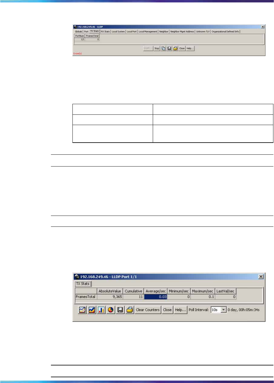
288 Configuring the switch using Device Manager
Figure 102
TX Stats tab
The following table describes the TX Stats tab fields.
Table 130
TX Stats tab fields
Field Description
PortNum port number
FramesTotal the number of LLDP frames transmitted by
this LLDP agent on the indicated port
—End—
Graphing LLDP transmit statistics
Use the following procedure to graph LLDP transmit statistics:
Step Action
1From the TX Stats tab, select the port for which you want to display
statistics.
2Click Graph.
The TX Stats – Graph dialog box appears.
3Highlight a data column to graph.
4Click one of the graph buttons.
—End—
Nortel Ethernet Routing Switch 2500 Series
Overview — System Configuration
NN47215-500 (323162-B) 02.02 Standard
4.1 19 November 2007
Copyright © 2007, Nortel Networks
.
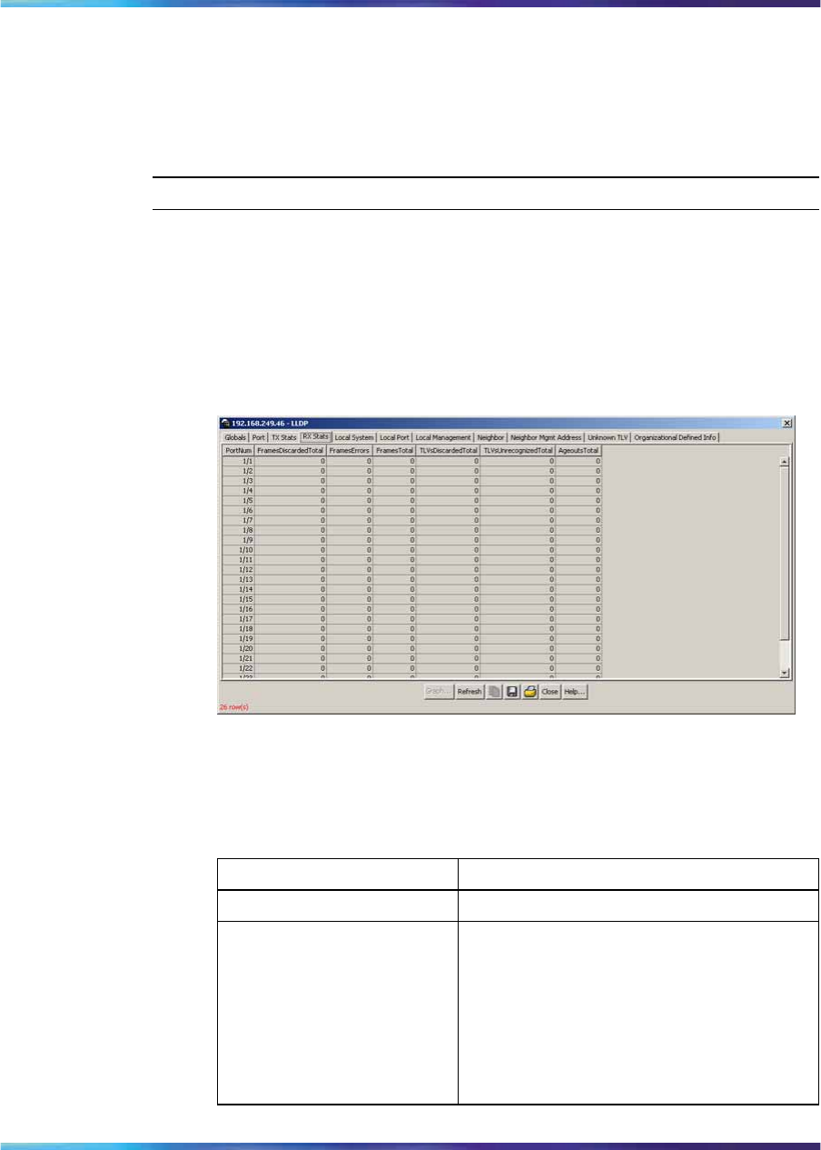
Configuring LLDP using Device Manager 289
RX Stats tab
With the RX Stats tab, you can view LLDP receive statistics by port.
Use the following procedure to open the RX Stats tab:
Step Action
1From the Device Manager menu bar, choose Edit > Diagnostics >
802.1ab > LLDP.
The LLDP dialog box appears with the Globals tab displayed.
2Click the RX Stats tab.
The RX Stats tab appears.
Figure 103
RX Stats tab
The following table describes the RX Stats tab fields.
Table 131
RX Stats tab fields
Field Description
PortNum Port number.
FramesDiscardedTotal The number of LLDP frames received on
the port and discarded for any reason. This
counter provides an indication that LLDP
header formatting problems exist with the
local LLDP agent in the sending system,
or that LLDPDU validation problems exist
with the local LLDP agent in the receiving
system.
Nortel Ethernet Routing Switch 2500 Series
Overview — System Configuration
NN47215-500 (323162-B) 02.02 Standard
4.1 19 November 2007
Copyright © 2007, Nortel Networks
.

290 Configuring the switch using Device Manager
Field Description
FramesErrors The number of invalid LLDP frames
received on the port, while the LLDP agent
is enabled.
FramesTotal The number of valid LLDP frames received
on the port, while the LLDP agent is
enabled.
TLVsDiscardedTotal The number of LLDP TLVs discarded for
any reason.
TLVsUnrecognizedTotal The number of LLDP TLVs received on
a given port that are not recognized by
this LLDP agent on the indicated port.
An unrecognized TLV is referred to as
the TLV whose type value is in the range
of reserved TLV types (000 1001 - 111
1110) in Table 9.1 of IEEE 802.1AB-2004.
An unrecognized TLV can be a basic
management TLV from a later LLDP
version.
AgeoutsTotal This counter represents the number of
age-outs that occurred on a given port.
An age-out is "the number of times the
complete set of information advertised by
a particular MSAP is deleted from tables
contained in lldpRemoteSystemsData
and lldpExtensions objects because
the information timeliness interval has
expired." This counter is similar to
lldpStatsRemTablesAgeouts, except that
it is on a per-port basis. This enables
NMS to poll tables associated with the
lldpRemoteSystemsData objects and all
LLDP extension objects associated with
remote systems on the indicated port only.
This counter is set to zero during agent
initialization. When the admin status for
a port changes from disabled to rxOnly,
txOnly or txAndRx, the counter associated
with the same port is reset to 0. The agent
also flushes all remote system information
associated with the same port. This
counter is incremented only once when the
complete set of information is invalidated
(aged out) from all related tables on a
particular port. Partial aging is not allowed,
and thus, does not change the value of
this counter.
Nortel Ethernet Routing Switch 2500 Series
Overview — System Configuration
NN47215-500 (323162-B) 02.02 Standard
4.1 19 November 2007
Copyright © 2007, Nortel Networks
.
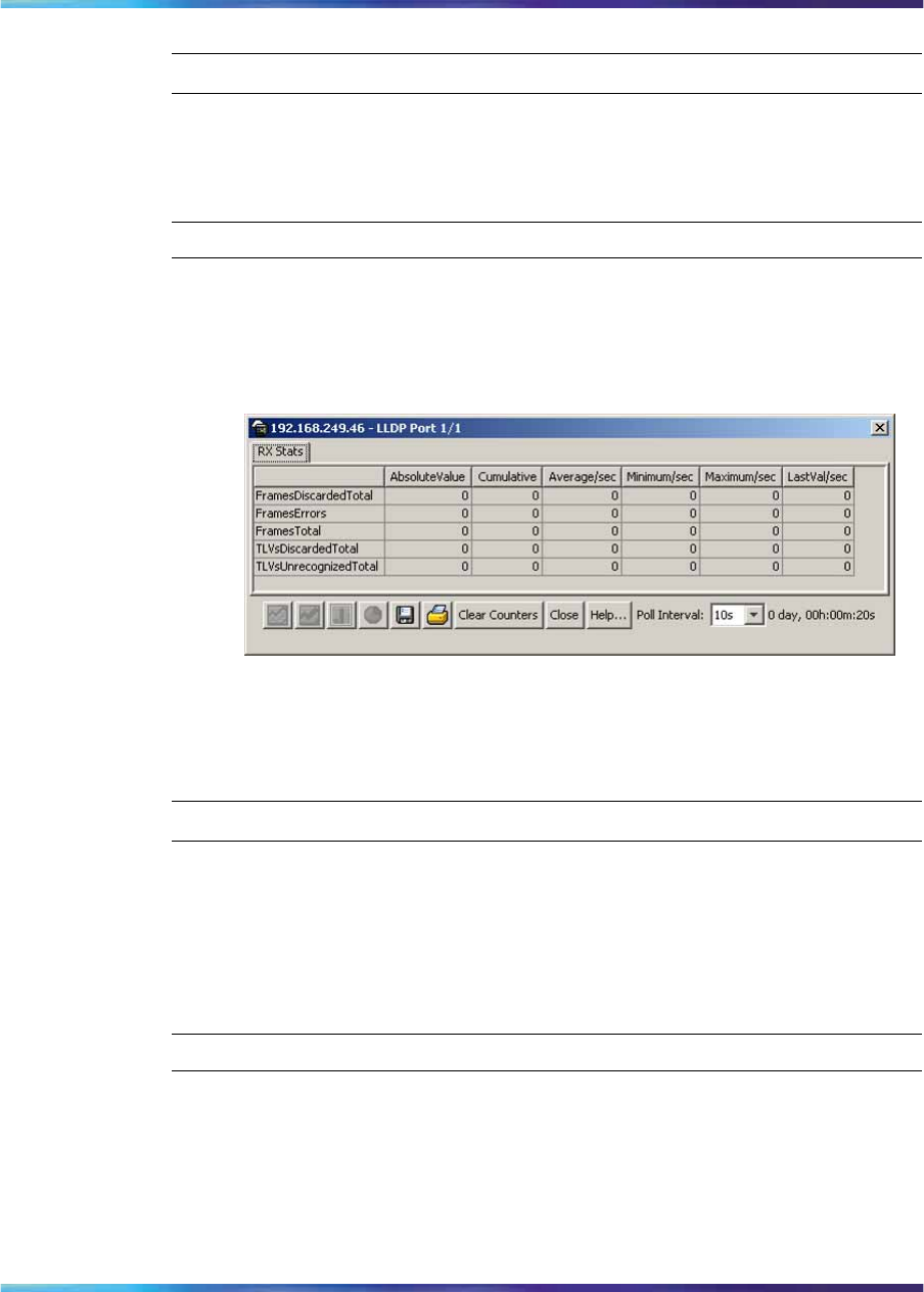
Configuring LLDP using Device Manager 291
—End—
Graphing LLDP receive statistics
Use the following procedure to graph LLDP receive statistics:
Step Action
1From the RX Stats tab, select the port for which you want to display
statistics.
2Click Graph.
The RX Stats – Graph dialog box appears.
3Highlight a data column to graph.
4Click one of the graph buttons.
—End—
Local System tab
With the Local System tab, you can view LLDP properties for the local
system.
Use the following procedure to open the Local System tab:
Step Action
1From the Device Manager menu bar, choose Edit > Diagnostics >
802.1ab > LLDP.
The LLDP dialog box appears with the Globals tab displayed.
2Select Local System.
The Local System tab appears.
Nortel Ethernet Routing Switch 2500 Series
Overview — System Configuration
NN47215-500 (323162-B) 02.02 Standard
4.1 19 November 2007
Copyright © 2007, Nortel Networks
.

292 Configuring the switch using Device Manager
Figure 104
Local System tab
The following table describes the Local System tab fields.
Table 132
Local System tab fields
Field Description
ChassisIdSubtype the type of encoding used to identify the
local system chassis:
•chassisComponent
•interfaceAlias
•portComponent
•macAddress
•networkAddress
•interfaceName
•local
ChassisId chassis ID
SysName local system name
SysDesc local system description
SysCapSupported identifies the system capabilities supported
on the local system
SysCapEnabled identifies the system capabilities that are
enabled on the local system
—End—
Local Port tab
With the Local Port tab, you can view LLDP port properties for the local
system.
Use the following procedure to open the Local Port tab:
Nortel Ethernet Routing Switch 2500 Series
Overview — System Configuration
NN47215-500 (323162-B) 02.02 Standard
4.1 19 November 2007
Copyright © 2007, Nortel Networks
.
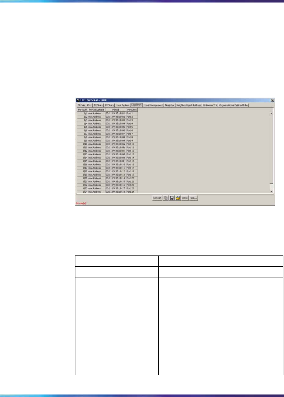
Configuring LLDP using Device Manager 293
Step Action
1From the Device Manager menu bar, choose Edit > Diagnostics >
802.1ab > LLDP.
The LLDP dialog box appears with the Globals tab displayed.
2Click the Local Port tab.
The Local Port tab appears.
Figure 105
Local Port tab
The following table describes the Local Port tab fields.
Table 133
Local Port tab fields
Field Description
PortNum Port number.
PortIdSubtype The type of port identifier encoding used in
the associated PortId object.
•interfaceAlias
•portComponent
•macAddress
•networkAddress
•interfaceName
•agentCircuitId
•local.
Nortel Ethernet Routing Switch 2500 Series
Overview — System Configuration
NN47215-500 (323162-B) 02.02 Standard
4.1 19 November 2007
Copyright © 2007, Nortel Networks
.
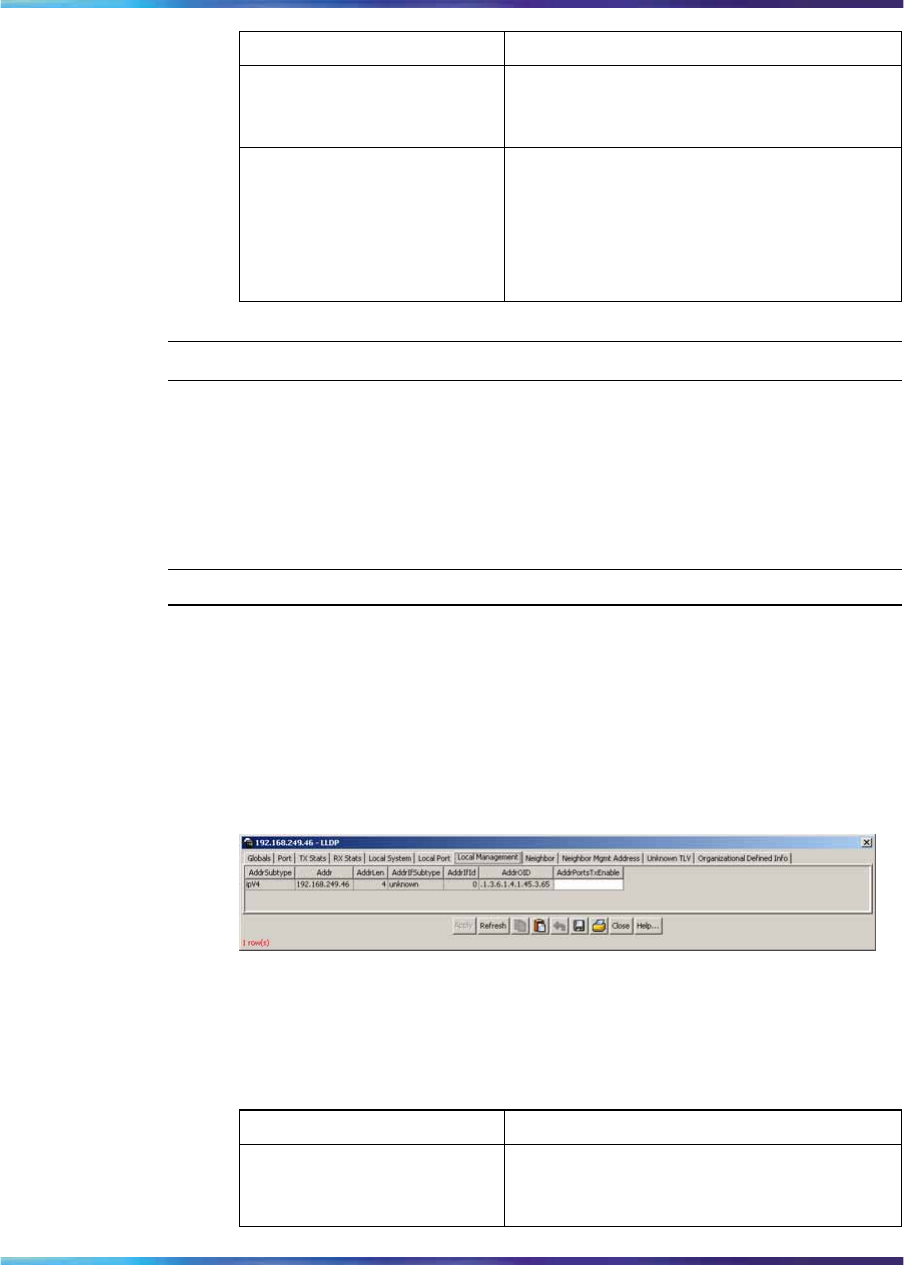
294 Configuring the switch using Device Manager
Field Description
PortId The string value used to identify the port
component associated with a given port in
the local system.
PortDesc The string value used to identify the 802
LAN station port description associated
with the local system. If the local agent
supports IETF RFC 2863, the PortDesc
object has the same value as the ifDescr
object.
—End—
Local Management tab
With the Local Management tab, you can view LLDP management
properties for the local system.
Use the following procedure to open the Local Management tab:
Step Action
1From the Device Manager menu bar, choose Edit > Diagnostics >
802.1ab > LLDP.
The LLDP dialog box appears with the Globals tab displayed.
2Click the Local Management tab.
The Local Management tab appears.
Figure 106
Local Management tab
The following table describes the Local Management tab fields.
Table 134
Local Management tab fields
Field Description
AddrSubtype The type of management address identifier
encoding used in the associated Addr
object.
Nortel Ethernet Routing Switch 2500 Series
Overview — System Configuration
NN47215-500 (323162-B) 02.02 Standard
4.1 19 November 2007
Copyright © 2007, Nortel Networks
.

Configuring LLDP using Device Manager 295
Field Description
Addr The string value used to identify the
management address component
associated with the local system. This
address is used to contact the management
entity.
AddrLen The total length of the management
address subtype and the management
address fields in LLDPDUs transmitted by
the local LLDP agent. The management
address length field is needed so
that the receiving systems that do not
implement SNMP are not required to
implement an iana family numbers/address
length equivalency table to decode the
management address.
AddrIfSubtype Identifies the numbering method used to
define the interface number associated
with the remote system.
•unknown
•ifIndex
•systemPortNumber
AddrIfId The integer value used to identify the
interface number of the management
address component associated with the
local system.
AddrOID The value used to identify the type of
hardware component or protocol entity
associated with the management address
advertised by the local system agent.
AddrPortsTxEnable Identifies the ports on which the local
system management address TLVs are
transmitted in the LLPDUs.
—End—
Neighbor tab
With the Neighbor tab, you can view LLDP properties for the remote system.
Use the following procedure to open the Neighbor tab:
Nortel Ethernet Routing Switch 2500 Series
Overview — System Configuration
NN47215-500 (323162-B) 02.02 Standard
4.1 19 November 2007
Copyright © 2007, Nortel Networks
.
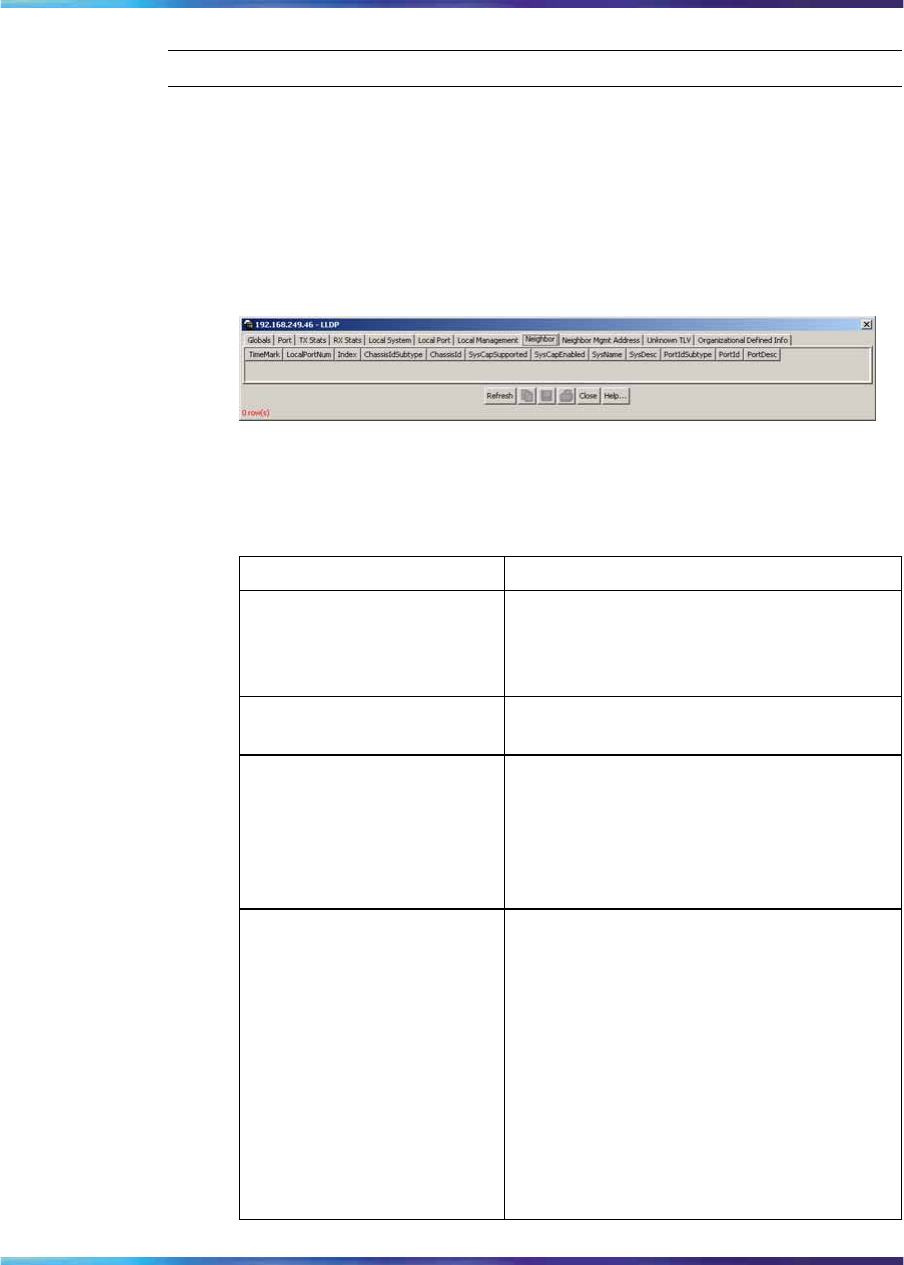
296 Configuring the switch using Device Manager
Step Action
1From the Device Manager menu bar, choose Edit > Diagnostics >
802.1ab > LLDP.
The LLDP dialog box appears with the Globals tab displayed.
2Click the Neighbor tab.
The Neighbor tab appears.
Figure 107
Neighbor tab
The following table describes the Neighbor tab fields.
Neighbor tab fields
Field Description
TimeMark The TimeFilter for this entry.
See the TimeFilter textual convention
in IETF RFC 2021 for details about
TimeFilter.
LocalPortNum Identifies the local port on which the remote
system information is received.
Index An arbitrary local integer value used
by this agent to identify a particular
MSAP. An agent is encouraged to assign
monotonically increasing index values to
new entries, starting with one, after each
reboot.
ChassisIdSubtype The type of encoding used to identify the
remote system chassis:
•chassisComponent
•interfaceAlias
•portComponent
•macAddress
•networkAddress
•interfaceName
•local.
Nortel Ethernet Routing Switch 2500 Series
Overview — System Configuration
NN47215-500 (323162-B) 02.02 Standard
4.1 19 November 2007
Copyright © 2007, Nortel Networks
.

Configuring LLDP using Device Manager 297
Field Description
ChassisId Remote chassis ID.
SysCapSupported Identifies the system capabilities supported
on the remote system.
SysCapEnabled Identifies the system capabilities that are
enabled on the remote system.
SysName Remote system name.
SysDesc Remote system description.
PortIdSubtype The type of encoding used to identify the
remote port.
•interfaceAlias
•portComponent
•macAddress
•networkAddress
•interfaceName
•agentCircuitId
•local
PortId Remote port ID.
PortDesc Remote port description.
—End—
Neighbor Mgmt Address tab
With the Neighbor Mgmt Address tab, you can view LLDP management
properties for the remote system.
Use the following procedure to open the Neighbor Mgmt Address tab:
Step Action
1From the Device Manager menu bar, choose Edit > Diagnostics >
802.1ab > LLDP.
The LLDP dialog box appears with the Globals tab displayed.
2Click the Neighbor Mgmt Address tab.
The Neighbor Mgmt Address tab appears.
Nortel Ethernet Routing Switch 2500 Series
Overview — System Configuration
NN47215-500 (323162-B) 02.02 Standard
4.1 19 November 2007
Copyright © 2007, Nortel Networks
.
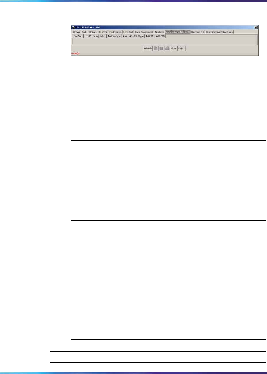
298 Configuring the switch using Device Manager
Figure 108
Neighbor Mgmt Address tab
The following table describes the Neighbor Mgmt Address tab fields.
Table 135
Neighbor Mgmt Address tab fields
Field Description
TimeMark The TimeFilter for this entry.
LocalPortNum Identifies the local port on which the remote
system information is received.
Index An arbitrary local integer value used
by this agent to identify a particular
MSAP. An agent is encouraged to assign
monotonically increasing index values to
new entries, starting with one, after each
reboot.
AddrSubtype The type of encoding used in the
associated Addr object.
Addr The management address associated with
the remote system.
AddrIfSubtype Identifies the numbering method used to
define the interface number associated
with the remote system.
•unknown
•ifIndex
•systemPortNumber
AddrIfId The integer value used to identify the
interface number of the management
address component associated with the
remote system.
AddrOID The value used to identify the type of
hardware component or protocol entity
associated with the management address
advertised by the remote system agent.
—End—
Nortel Ethernet Routing Switch 2500 Series
Overview — System Configuration
NN47215-500 (323162-B) 02.02 Standard
4.1 19 November 2007
Copyright © 2007, Nortel Networks
.
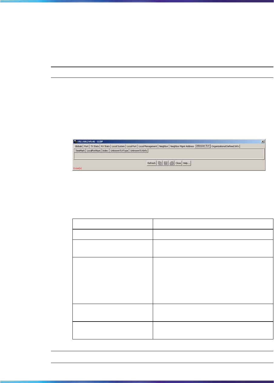
Configuring LLDP using Device Manager 299
Unknown TLV tab
With the Unknown TLV tab, you can view details about unknown TLVs
received on the local system.
Use the following procedure to open the Unknown TLV tab:
Step Action
1From the Device Manager menu bar, choose Edit > Diagnostics >
802.1ab > LLDP.
The LLDP dialog box appears with the Globals tab displayed.
2Click the Unknown TLV tab.
The Unkown TLV tab appears.
Unknown TLV tab
The following table describes the Unknown TLV tab fields.
Table 136
Unknown TLV tab fields
Field Description
TimeMark The TimeFilter for this entry.
LocalPortNum Identifies the local port on which the remote
system information is received.
Index An arbitrary local integer value used
by this agent to identify a particular
MSAP. An agent is encouraged to assign
monotonically increasing index values to
new entries, starting with one, after each
reboot.
UnknownTLVType The value extracted from the type field of
the unknown TLV.
UnknownTLVInfo The value extracted from the value field of
the unknown TLV.
—End—
Nortel Ethernet Routing Switch 2500 Series
Overview — System Configuration
NN47215-500 (323162-B) 02.02 Standard
4.1 19 November 2007
Copyright © 2007, Nortel Networks
.
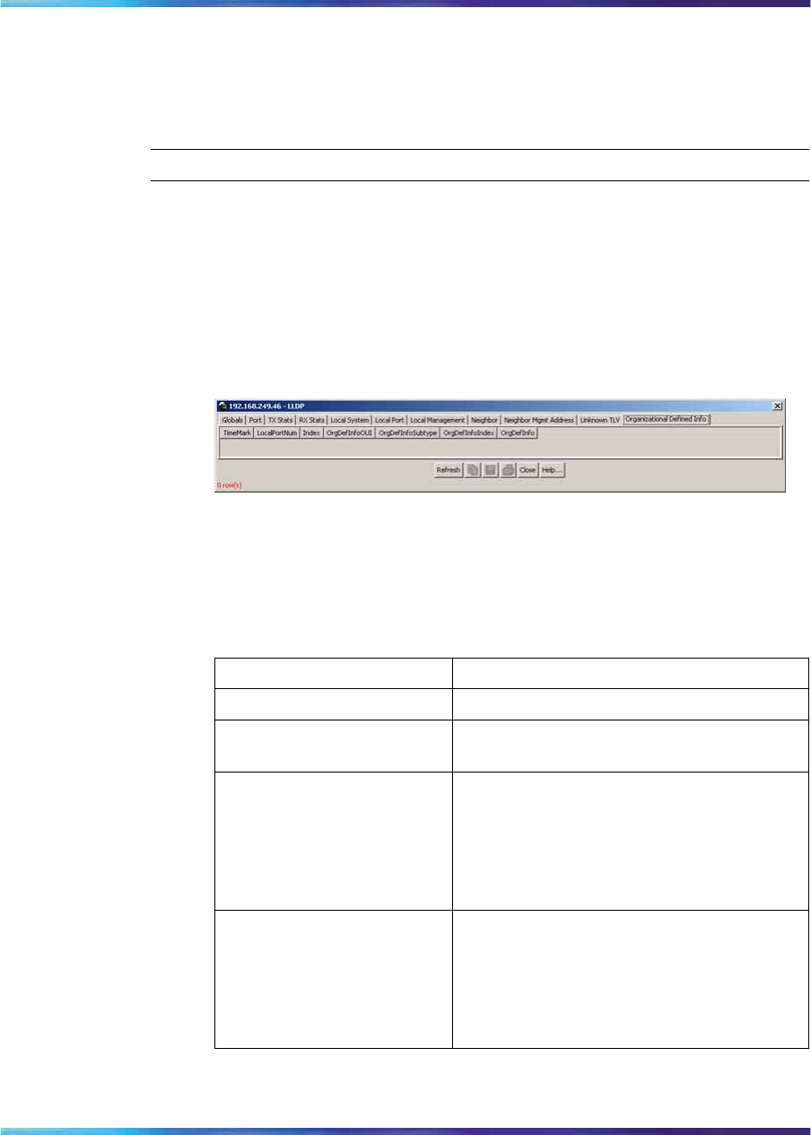
300 Configuring the switch using Device Manager
Organizational Defined Info tab
With the Organizational Defined Info tab, you can view organizationally
specific properties for the remote system.
Use the following procedure to open the Organizational Defined Info tab:
Step Action
1From the Device Manager menu bar, choose Edit > Diagnostics >
802.1ab > LLDP.
The LLDP dialog box appears with the Globals tab displayed.
2Click the Organizational Defined Info tab.
The Organizational Defined Info tab appears.
Figure 109
Organizational Defined Info tab
The following table describes the Organizational Defined Info tab
fields.
Table 137
Organizational Defined Info tab fields
Field Description
TimeMark The TimeFilter for this entry.
LocalPortNum Identifies the local port on which the remote
system information is received.
Index An arbitrary local integer value used
by this agent to identify a particular
MSAP. An agent is encouraged to assign
monotonically increasing index values to
new entries, starting with one, after each
reboot.
OrgDefInfoOUI The Organizationally Unique Identifier
(OUI), as defined in IEEE 802-2001, is a 24
bit (three octets) globally unique assigned
number referenced by various standards,
of the information received from the remote
system.
Nortel Ethernet Routing Switch 2500 Series
Overview — System Configuration
NN47215-500 (323162-B) 02.02 Standard
4.1 19 November 2007
Copyright © 2007, Nortel Networks
.

Configuring LLDP using Device Manager 301
Field Description
OrgDefInfoSubtype The integer value used to identify
the subtype of the organizationally
defined information received from the
remote system. The subtype value is
required to identify different instances
of organizationally defined information
that cannot be retrieved without a unique
identifier that indicates the particular type
of information contained in the information
string.
OrgDefInfoIndex This object represents an arbitrary local
integer value used by this agent to identify
a particular unrecognized organizationally
defined information instance, unique
only for the OrgDefInfoOUI and
lldpRemOrgDefInfoSubtype of the same
remote system. An agent is encouraged
to assign monotonically increasing index
values to new entries, starting with one,
after each reboot. It is unlikely that the
lldpRemOrgDefInfoIndex wraps between
reboots.
OrdDefInfo The string value used to identify the
organizationally defined information of the
remote system. The encoding for this
object is the same as that defined for
SnmpAdminString TC.
—End—
Nortel Ethernet Routing Switch 2500 Series
Overview — System Configuration
NN47215-500 (323162-B) 02.02 Standard
4.1 19 November 2007
Copyright © 2007, Nortel Networks
.

302 Configuring the switch using Device Manager
Nortel Ethernet Routing Switch 2500 Series
Overview — System Configuration
NN47215-500 (323162-B) 02.02 Standard
4.1 19 November 2007
Copyright © 2007, Nortel Networks
.

303
Configuring ports using Device
Manager
This chapter describes how to use Device Manager to configure ports on an
Ethernet Routing Switch 2500 Series.
The windows displayed when you configure a single port differ from the
ones displayed when you configure multiple ports. However, the options
are similar.
This section covers:
•"Viewing and editing a single port configuration" (page 303)
•"Viewing and editing multiple port configurations" (page 307)
Viewing and editing a single port configuration
To view or edit the configuration of a single port, use the following procedure:
→Do one of the following:
•Double-click on a single port.
•From the Device Manager main menu, choose Edit > Port.
•From the shortcut menu, choose Edit.
•From the toolbar, click Edit.
ATTENTION
When you edit a single port, tabs that are not applicable are not available for
you to select.
When you edit multiple ports, some tabs are not available, and some tabs are
available even though the options are not applicable. When the option does not
apply for a given port, NoSuchObject is displayed.
Nortel Ethernet Routing Switch 2500 Series
Overview — System Configuration
NN47215-500 (323162-B) 02.02 Standard
4.1 19 November 2007
Copyright © 2007, Nortel Networks
.

304 Configuring ports using Device Manager
The following sections provide a description of the Edit Port dialog box, and
details about the fields in the Interface tab:
•"Interface tab for a single port" (page 304)
•"Interface tab for multiple ports" (page 308)
Interface tab for a single port
The Interface tab shows the basic configuration and status of a single port.
To view the Interface tab, use the following procedure:
Step Action
1Select the port you want to edit.
2Do one of the following:
•Double-click on the selected port.
•From the Device Manager main menu, choose Edit > Port.
•From the shortcut menu, choose Edit.
•From the toolbar, click Edit.
The Port dialog box for a single port appears with the Interface
tab displayed.
Nortel Ethernet Routing Switch 2500 Series
Overview — System Configuration
NN47215-500 (323162-B) 02.02 Standard
4.1 19 November 2007
Copyright © 2007, Nortel Networks
.
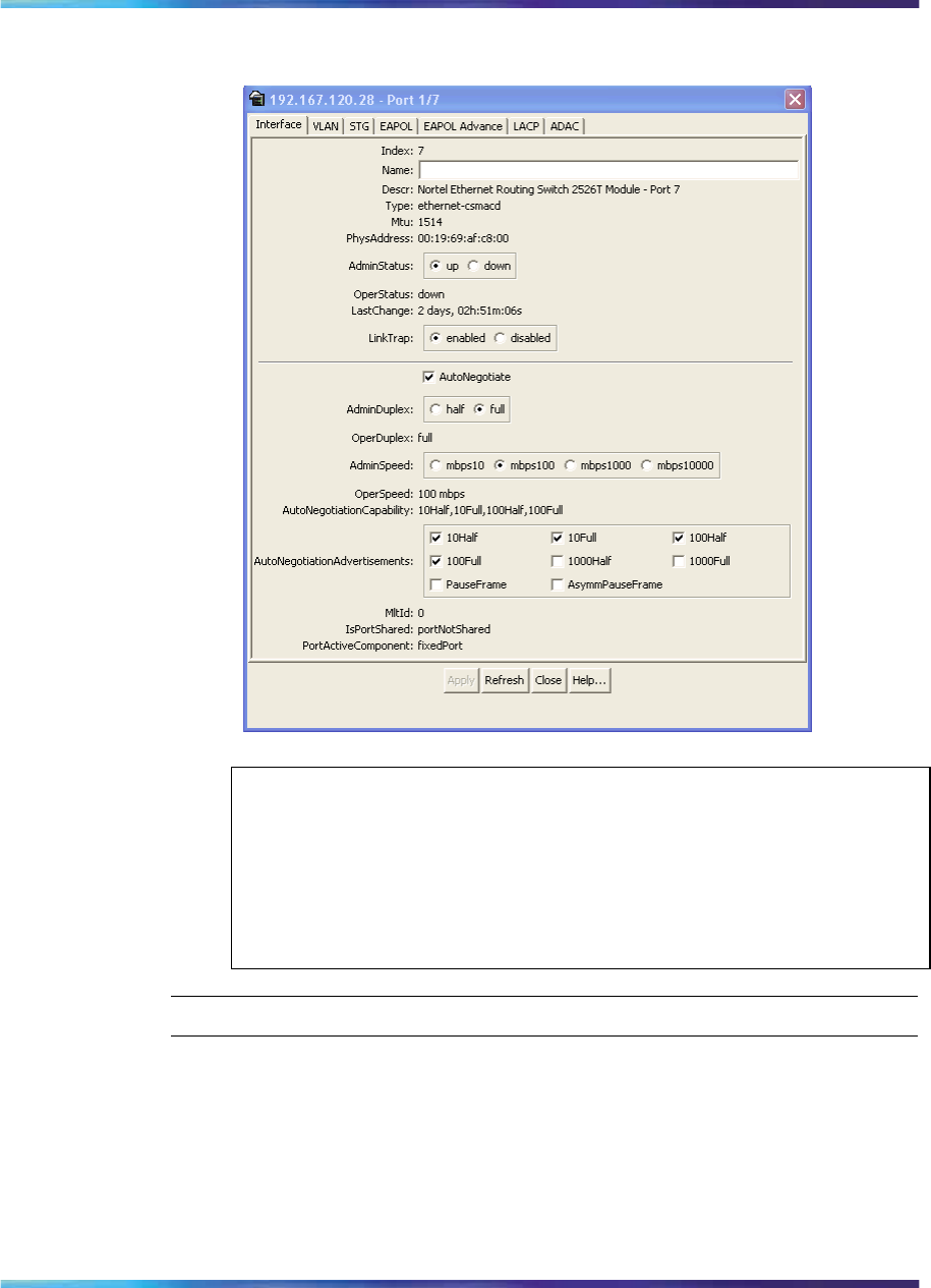
Viewing and editing a single port configuration 305
Figure 110
Port dialog box Interface tab
ATTENTION
10/100BASE-TX ports may not autonegotiate correctly with older
10/100BASE-TX equipment. In some cases, the older devices can
be upgraded with new firmware or driver revisions. If an upgrade does
not allow autonegotiation to correctly identify the link speed and duplex
settings, you can manually configure the settings for the link in question.
—End—
•"Interface tab fields" (page 305)
Interface tab fields
Table 138 "Interface tab fields for a single port" (page 306) describes the
Interface tab fields for a single port.
Nortel Ethernet Routing Switch 2500 Series
Overview — System Configuration
NN47215-500 (323162-B) 02.02 Standard
4.1 19 November 2007
Copyright © 2007, Nortel Networks
.

306 Configuring ports using Device Manager
Table 138
Interface tab fields for a single port
Field Description
Index A unique value assigned to each interface. The value ranges
between 1 and 512.
Name Specifies a name for the port.
Descr The description of the selected port.
Type The media type of this interface.
Mtu The size of the largest packet, in octets, that can be sent or received
on the interface.
PhysAddress The MAC address assigned to a particular interface.
AdminStatus The current administrative state of the device, which can be one of
the following:
•up
•down
When a managed system is initialized, all interfaces start with
AdminStatus in the up state. AdminStatus changes to the down state
(or remains in the up state) as a result of either management action
or the configuration information available to the managed system.
OperStatus The current operational state of the interface, which can be one of
the following:
•up
•down
•testing
If AdminStatus is up, then OperStatus should be up if the interface is
ready to transmit and receive network traffic. If AdminStatus is down,
then OperStatus should be down. It should remain in the down state
if and only if there is a fault that prevents it from going to the up state.
The testing state indicates that no operational packets can be passed.
LastChange The value of sysUpTime at the time the interface entered its current
operational state. If the current state was entered prior to the last
reinitialization of the local network management subsystem, the value
is zero.
LinkTrap Specifies whether linkUp/linkDown traps should be generated for
this interface.
AutoNegotiate Indicates whether this port is enabled for autonegotiation or not.
AdminDuplex The current administrative duplex mode of the port (half or full).
Nortel Ethernet Routing Switch 2500 Series
Overview — System Configuration
NN47215-500 (323162-B) 02.02 Standard
4.1 19 November 2007
Copyright © 2007, Nortel Networks
.

Viewing and editing multiple port configurations 307
Field Description
OperDuplex The current mode of the port (half duplex or full duplex).
AdminSpeed Set the port’s speed.
OperSpeed The current operating speed of the port.
AutoNegotiationCapability Specifies the port speed and duplex capabilities that a switch can
support on a port, and that may be advertised by the port using
auto-negotiation.
AutoNegotiation
Advertisments Specifies the port speed and duplex abilities to be advertised during
link negotiation.
MltId The MultiLink Trunk to which the port is assigned (if any).
IsPortShared Specifies whether a port is shared. Multiple ports that are logically
represented as a single port are shared. Only one shared port may
be active at a time.
PortActiveComponent Specifies the physical port components that are active for a shared
port.
•"Viewing and editing multiple port configurations" (page 307)
•"Interface tab for multiple ports" (page 308)
Viewing and editing multiple port configurations
To view or edit the configurations of multiple ports:
Step Action
1Select the ports you want to edit.
Press Ctrl+left click the ports you want to view or configure. A
yellow outline appears around the selected ports.
2Do one of the following:
•From the shortcut menu, choose Edit.
•From the Device Manager main menu, choose Edit > Port.
•From the shortcut menu, choose Edit.
•From the toolbar, click Edit.
Nortel Ethernet Routing Switch 2500 Series
Overview — System Configuration
NN47215-500 (323162-B) 02.02 Standard
4.1 19 November 2007
Copyright © 2007, Nortel Networks
.
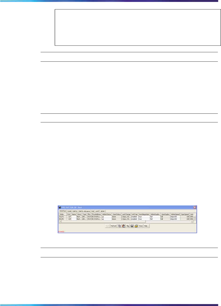
308 Configuring ports using Device Manager
ATTENTION
When you edit multiple ports, some tabs are not available, and some tabs
are available even though the options are not applicable. When the option
does not apply for a given port, NoSuchObject is displayed.
—End—
Interface tab for multiple ports
The Interface tab shows the basic configuration and status of the selected
ports.
To view or edit the Interface tab for multiple ports, use the following
procedure:
Step Action
1Select the ports that you want to edit.
Press Ctrl+left click the ports that you want to configure. A yellow
outline appears around the selected ports.
2Do one of the following:
•From the shortcut menu, choose Edit.
•From the Device Manager main menu, choose Edit > Port.
The Interface tab shows port interface statistics.
Figure 111
Interface tab for multiple ports
—End—
Table 139 "Interface tab fields for multiple ports" (page 309) describes the
Interface tab fields for multiple ports.
Nortel Ethernet Routing Switch 2500 Series
Overview — System Configuration
NN47215-500 (323162-B) 02.02 Standard
4.1 19 November 2007
Copyright © 2007, Nortel Networks
.

Viewing and editing multiple port configurations 309
Table 139
Interface tab fields for multiple ports
Field Description
Index A unique value assigned to each interface. The value
ranges between 1 and 512.
Port Port Id in unit and port format.
Name Lets you enter a character string to name the port
Descr Type of switch and number of ports.
Type Media type for this interface.
Mtu Size of the largest packet, in octets, that can be sent or
received on the interface.
PhysAddress MAC address assigned to a particular interface.
AdminStatus Current administrative state of the device, which can be
one of the following:
•up
•down
When a managed system is initialized, all interfaces start
with AdminStatus in the up state. AdminStatus changes to
the down state (or remains in the up state) as a result of
either management action or the configuration information
available to the managed system.
OperStatus Current operational state of the interface, which can be
one of the following:
•up
•down
•testing
If AdminStatus is up, then OperStatus should be up if the
interface is ready to transmit and receive network traffic. If
AdminStatus is down, then OperStatus should be down.
It should remain in the down state if and only if there is a
fault that prevents it from going to the up state. The testing
state indicates that no operational packets can be passed.
LastChange Value of the time the interface entered its current
operational state. If the current state was entered prior to
the last reinitialization of the local network management
subsystem, the value is zero.
LinkTrap Specifies whether linkUp/linkDown traps should be
generated for this interface
Nortel Ethernet Routing Switch 2500 Series
Overview — System Configuration
NN47215-500 (323162-B) 02.02 Standard
4.1 19 November 2007
Copyright © 2007, Nortel Networks
.

310 Configuring ports using Device Manager
Field Description
Auto
Negotiate Indicates whether the port is enabled (checked) for
autonegotiation or not.
AdminDuplex The current administrative duplex mode of the port (half
or full).
OperDuplex Indicate current duplex value of the port.
AdminSpeed Set the speed of a port: none, mbps10, and mbps100.
OperSpeed The current operating speed of the port.
AutoNegotiation
Capability Specifies the port speed and duplex capabilities that a
switch can support on a port, and that may be advertised
by the port using auto-negotiation
AutoNegotiation
Advertisments Specifies the port speed and duplex abilities to be
advertised during link negotiation.
MltId The MultiLink Trunk to which the port is assigned (if any).
IsPortShared Specifies whether a port is shared. Multiple ports that are
logically represented as a single port are shared. Only
one shared port may be active at a time.
PortActive
Component Specifies the physical port components that are active
for a shared port.
Nortel Ethernet Routing Switch 2500 Series
Overview — System Configuration
NN47215-500 (323162-B) 02.02 Standard
4.1 19 November 2007
Copyright © 2007, Nortel Networks
.

311
Administering the switch using
web-based management
The administrative options available to you are:
•"Viewing system information" (page 311)
•"Quick Start" (page 312)
•"Configuring system security" (page 314)
•"Rebooting the Ethernet Routing Switch 2500 Series" (page 315)
•"Changing the Ethernet Routing Switch 2500 Series to system defaults"
(page 316)
•"Logging out of the management interface" (page 316)
Viewing system information
You can view an image of the Ethernet Routing Switch 2500 Series,
information about the host device and, if provided, the contact person
or manager for the switch. The System Information page is also the
web-based management interface home page.
To view system information, use the following procedure:
→From the main menu, choose Administration > System Information.
The System Information page appears.
ATTENTION
You may create or modify existing system information parameters using the
System page.For more information on configuring system information, see
"Modifying system settings" (page 322).
Nortel Ethernet Routing Switch 2500 Series
Overview — System Configuration
NN47215-500 (323162-B) 02.02 Standard
4.1 19 November 2007
Copyright © 2007, Nortel Networks
.
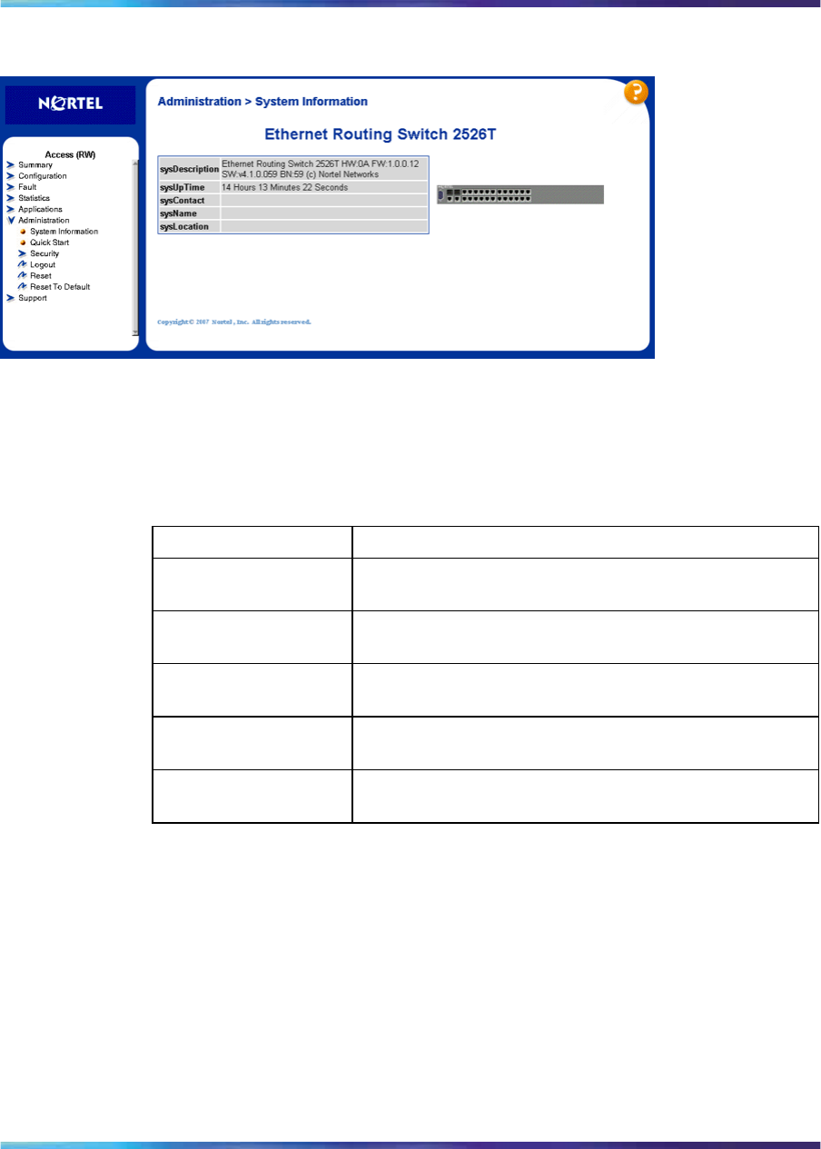
312 Administering the switch using web-based management
Figure 112
System Information page
Table 140 "System Information page items" (page 312) describes the items
on the System Information page.
Table 140
System Information page items
Item Description
sysDescription The default description of the Ethernet Routing Switch
2500 Series.
sysUpTime The elapsed time since the last network management
portion of the system was last re-initialized.
sysName The name created by the network administrator to
identify the switch, for example, Finance Group.
sysLocation The location name created by the network administrator
to identify the switch location, for example, first floor.
sysContact The name, email, address, and telephone number of the
person to contact about switch operation.
Quick Start The Quick Start feature lets the administrator of the Ethernet Routing Switch
2500 Series make the initial setup by consolidating multiple setup pages
into a single page. The Quick Start screen allows the administrator to
configure the following information:
•IP address
•Subnet mask
•Default gateway
•SNMP Read community
Nortel Ethernet Routing Switch 2500 Series
Overview — System Configuration
NN47215-500 (323162-B) 02.02 Standard
4.1 19 November 2007
Copyright © 2007, Nortel Networks
.
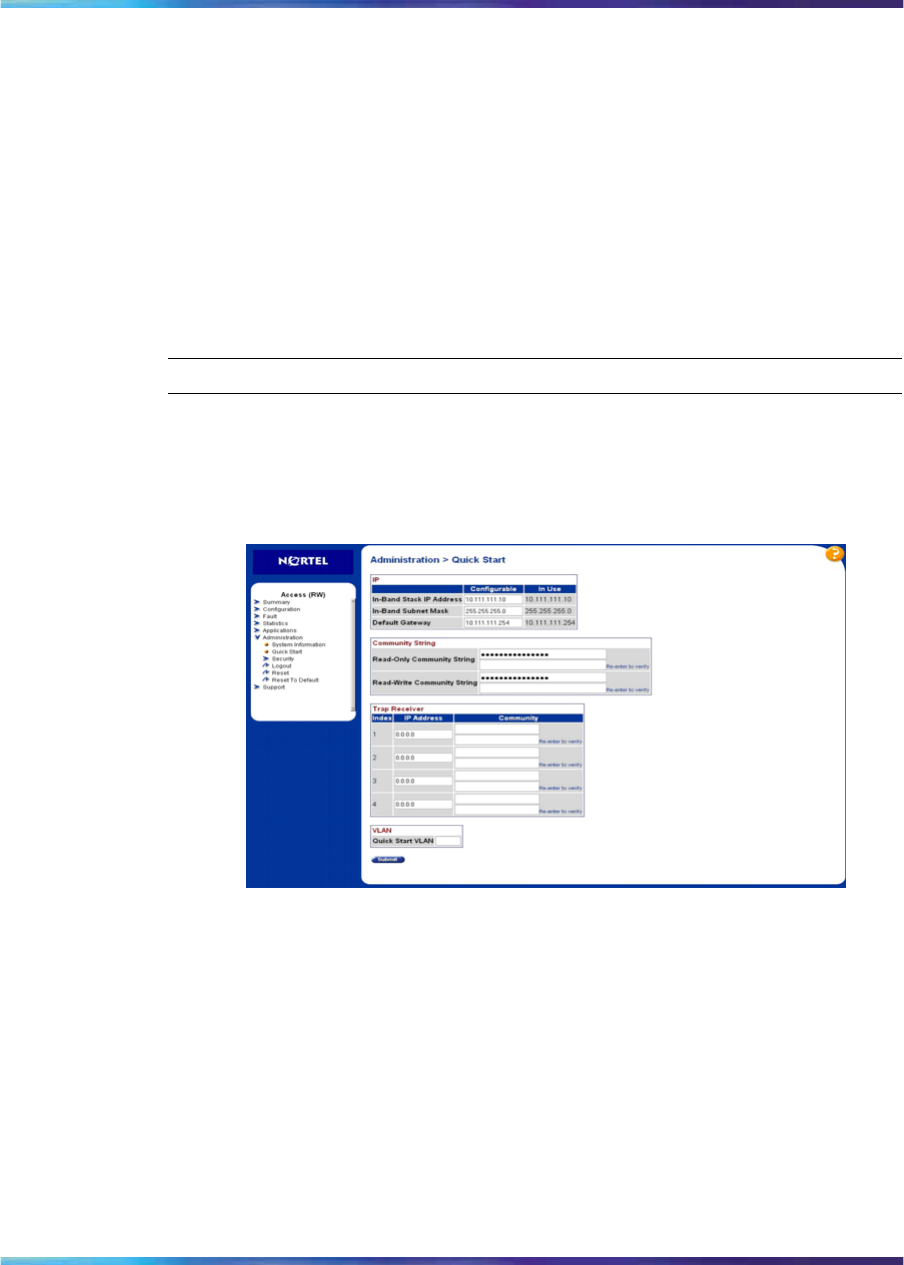
Quick Start 313
•SNMP Write community
•SNMP Trap IP addresses and communities (up to four)
•New default VLAN
During the initial setup mode, all ports are assigned to the new default VLAN.
A port-based Quick Start VLAN is created if the new default VLAN does not
exist. All ports are removed from the current default VLAN and assigned to
the Quick Start VLAN. The PVIDs for all ports are changed to the Quick Start
VLAN. The Quick Start VLAN is also designated as the management VLAN.
To configure the initial settings using the Quick Start feature:
Step Action
1From the main menu, select Administration > Quick Start.
The Quick Start page is displayed.
Figure 113
Quick Start page
2Click on the Submit button after making the required settings.
The following table describes the items on the Quick Start page.
Nortel Ethernet Routing Switch 2500 Series
Overview — System Configuration
NN47215-500 (323162-B) 02.02 Standard
4.1 19 November 2007
Copyright © 2007, Nortel Networks
.

314 Administering the switch using web-based management
Table 141
Items on the Quick Start page
Section Item Description
In-Band Switch
IP Address Specify a new IP address for the
switch.
In-Band Subnet
Mask Enter a new subnet mask.
IP
Default
Gateway Specify an IP address for the
default gateway.
Read-Only
Community
String
Specify a character string to
identify the community string for the
SNMPv1 Read-Only community,
for example, public or private.
Re-enter character string to verify.
The default value is public.
Community
String
Read-Write
Community
String
Specify a character string to
identify the community string for the
SNMPv1 Read-Write community,
for example, public or private.
Re-enter character string to verify.
The default value is private.
Index Select the number of the Trap
Receiver to create or modify.
IP address Specify the network address for the
SNMP Manager that is to receive
the specified Trap.
Trap Receiver
Community Type the Community String for the
specified Trap Receiver. Re-enter
Community String to verify.
VLAN Quick Start
VLAN Specify the IP of the port-based
Quick Start VLAN.
—End—
Configuring system security
For information on configuring system security, please see Nortel Ethernet
Routing Switch 2500 Series Security — Configuration and Management
(NN47215-505).
Nortel Ethernet Routing Switch 2500 Series
Overview — System Configuration
NN47215-500 (323162-B) 02.02 Standard
4.1 19 November 2007
Copyright © 2007, Nortel Networks
.
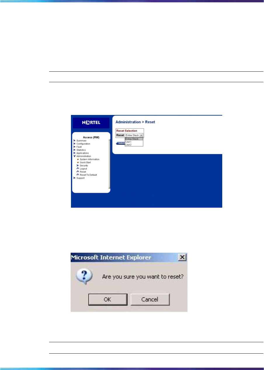
Rebooting the Ethernet Routing Switch 2500 Series 315
Rebooting the Ethernet Routing Switch 2500 Series
You can reboot a unit in stack or an entire stack without erasing any
configured switch parameters. While rebooting, the switch initiates a
self-test that comprises various diagnostic routines and subtests. The LEDs
display various patterns to indicate that the subtests are in progress.
To reboot the Ethernet Routing Switch 2500 Series without making changes
(since your last Submit request):
Step Action
1From the main menu, choose Administration > Reset.
Figure 114
Reset page
The reset warning message displays.
Figure 115
Reset page message
2Click OK.
—End—
Nortel Ethernet Routing Switch 2500 Series
Overview — System Configuration
NN47215-500 (323162-B) 02.02 Standard
4.1 19 November 2007
Copyright © 2007, Nortel Networks
.
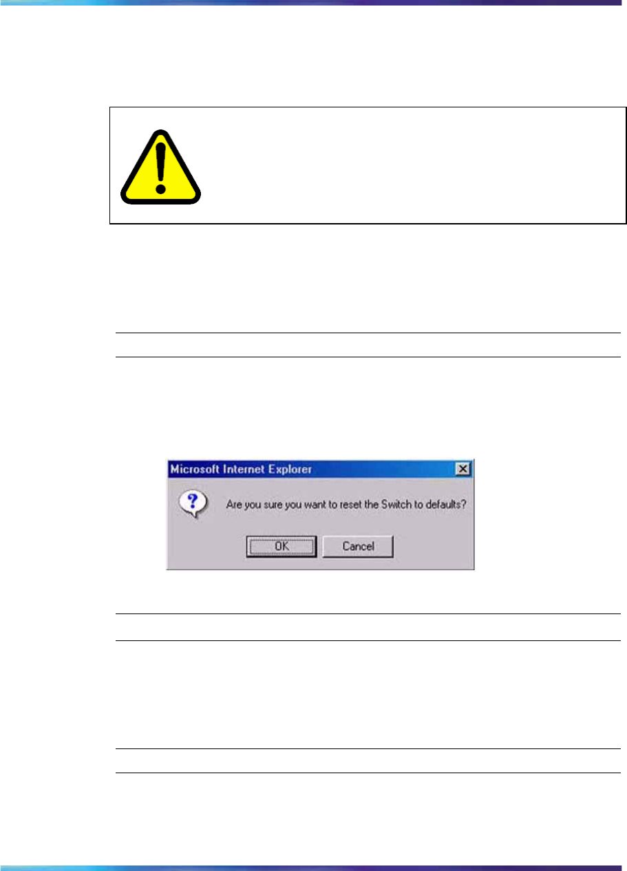
316 Administering the switch using web-based management
Changing the Ethernet Routing Switch 2500 Series to system
defaults You can replace all configured switch parameters with the factory default
values.
CAUTION
If you choose change to default settings, all configured settings
are replaced with factory default settings when you click Submit.
For more information about factory default settings, see Appendix
"Default settings" (page 343).
During the process of changing to default settings, the switch initiates a
self-test that comprises various diagnostic routines and subtests. The LEDs
display various patterns to indicate that the subtests are in progress.
To change the Ethernet Routing Switch 2500 Series to system defaults:
Step Action
1From the main menu, choose Administration > Reset to Default.
The reset to default warning message displays.
Figure 116
Reset to Default page message
—End—
Logging out of the management interface
To log out of the Web-based management interface, use the following
procedure:
Step Action
1From the main menu, choose Administration > Logout.
A logout message displays.
Nortel Ethernet Routing Switch 2500 Series
Overview — System Configuration
NN47215-500 (323162-B) 02.02 Standard
4.1 19 November 2007
Copyright © 2007, Nortel Networks
.
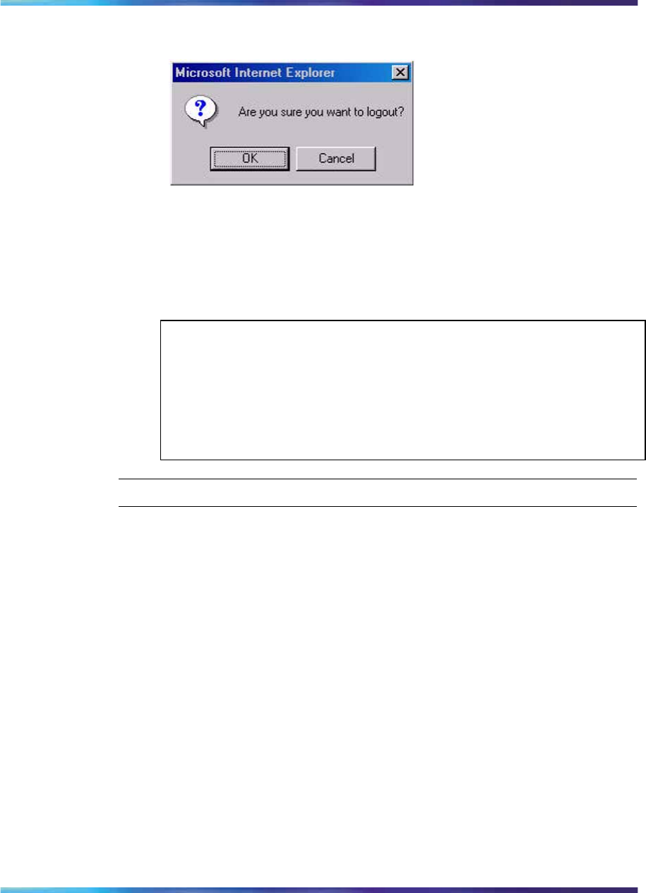
Logging out of the management interface 317
Figure 117
Logout message
2Do one of the following:
•Click OK to log out.
•Click Cancel to return to the web-based management interface
home page.
ATTENTION
If you have not configured system password security, a reset returns you
to the home page. If you have configured system password security, a
reset returns you to a log on page (for details on configuring management
passwords, see Nortel Ethernet Routing Switch 2500 Series Security —
Configuration and Management (NN47215-505)).
—End—
Nortel Ethernet Routing Switch 2500 Series
Overview — System Configuration
NN47215-500 (323162-B) 02.02 Standard
4.1 19 November 2007
Copyright © 2007, Nortel Networks
.

318 Administering the switch using web-based management
Nortel Ethernet Routing Switch 2500 Series
Overview — System Configuration
NN47215-500 (323162-B) 02.02 Standard
4.1 19 November 2007
Copyright © 2007, Nortel Networks
.

319
Configuring the switch using web-based
management
The switch configuration options available to you are:
•"Configuring BootP, IP, and gateway settings" (page 319)
•"Modifying system settings" (page 322)
•"Configuring switch port status" (page 324)
•"Configuring high speed flow control" (page 327)
•"Downloading switch images" (page 328)
•"Downloading ASCII configuration files" (page 330)
•"Storing and retrieving a switch configuration file from a TFTP server"
(page 331)
•"Enabling and disabling autosave" (page 333)
•"Configuring port communication speed" (page 334)
•"Configuring Rate Limiting" (page 335)
Configuring BootP, IP, and gateway settings
You can configure the BootP mode settings, create and modify the In-band
switch IP addresses and In-band subnet mask parameters, and configure
the IP address of your default gateway.
ATTENTION
Settings take effect immediately when you click Submit.
To configure BootP, IP, and gateway settings, use the following procedure:
Step Action
1From the main menu, choose Configuration > IP.
The IP page appears.
Nortel Ethernet Routing Switch 2500 Series
Overview — System Configuration
NN47215-500 (323162-B) 02.02 Standard
4.1 19 November 2007
Copyright © 2007, Nortel Networks
.
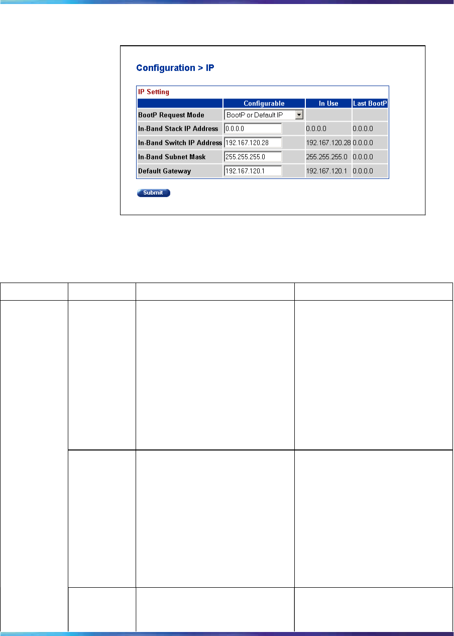
320 Configuring the switch using web-based management
Figure 118
IP page
The following table describes the items on the IP page.
Table 142
IP page items
Section Item Range Description
BootP
Request
Mode
BootP or Default IP (default) Choose this mode to inform the
switch to send a BootP request
when the switch IP address
stored in nonvolatile memory is
the factory default value. If the
stored IP address differs from
the factory default value, the
switch uses the stored network
parameters. If the switch cannot
find a BootP server, it tries five
more times to find one and then
defaults to the factory settings
BootP Always Choose this mode to inform
the switch to ignore any stored
network parameters and send
a BootP request, each time it
boots. If the BootP request
fails, the switch boots with the
factory default IP configuration.
This setting disables remote
management if no BootP server
is set up for the switch, but lets
the switch boot normally.
BootP Disabled Choose this mode to inform the
switch to use the IP configuration
parameters stored in nonvolatile
Boot Mode
Setting
Nortel Ethernet Routing Switch 2500 Series
Overview — System Configuration
NN47215-500 (323162-B) 02.02 Standard
4.1 19 November 2007
Copyright © 2007, Nortel Networks
.

Configuring BootP, IP, and gateway settings 321
Section Item Range Description
memory, each time the switch
boots. If a BootP configuration
is in progress when you issue
this command, the BootP
configuration stops.
BootP or Last Address Choose this mode to inform
the switch at each startup,
to obtain its IP configuration
using BootP. If the BootP
request fails, the switch uses
the network parameters stored
in its nonvolatile memory.
ATTENTION
Valid parameters obtained in
using BootP always replace
current information stored in
the nonvolatile memory.
ATTENTION
Whenever the switch is broadcasting BootP requests, the BootP
process times out if a reply is not received within 7 minutes
(approximately). When the process times out, the BootP request
mode automatically changes to BootP Disabled mode. To restart
the BootP process, change the BootP request mode to any of
the three following modes: BootP or Default IP, BootP Always,
or to BootP or Last Address.
In-Band
Stack IP
Address
XXX.XXX.XXX.XXX Type a new stack IP address in
the appropriate format.
In-Band
Switch IP XXX.XXX.XXX.XXX Type a new switch IP address
in the appropriate format.
IP Setting
Nortel Ethernet Routing Switch 2500 Series
Overview — System Configuration
NN47215-500 (323162-B) 02.02 Standard
4.1 19 November 2007
Copyright © 2007, Nortel Networks
.

322 Configuring the switch using web-based management
Section Item Range Description
Address
ATTENTION
When the IP address is
entered in the In-Band
IP Address field, and the
In-Band Subnet Mask field
value is not present, the
software provides an in-use
default value for the In-Band
Subnet Mask field that is
based on the class of the
IP address entered in the
In-Band IP Address field.
In-Band
Subnet Mast XXX.XXX.XXX.XXX Type a new subnet mask in the
appropriate format.
Network routers use the subnet
mask to determine the network or
subnet address portion of a host’s
IP address. The bits in the IP
address that contain the network
address (including the subnet)
are set to 1 in the address mask,
and the bits that contain the host
identifier are set to 0.
Gateway
Setting Default
Gateway XXX.XXX.XXX.XXX Type an IP address for the default
gateway in the appropriate
format.
2Type information in the text boxes, or select from a list.
3Click Submit.
—End—
Modifying system settings
You can create or modify the system name, system location, and network
manager contact information.
Nortel Ethernet Routing Switch 2500 Series
Overview — System Configuration
NN47215-500 (323162-B) 02.02 Standard
4.1 19 November 2007
Copyright © 2007, Nortel Networks
.
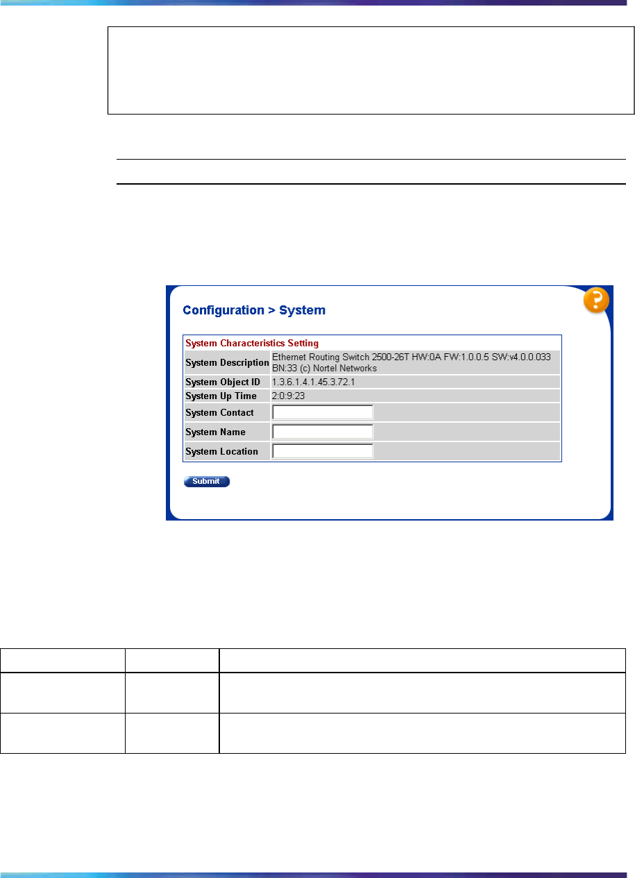
Modifying system settings 323
ATTENTION
The configurable parameters on the System page are displayed in a read only
format on the System Information home page.
To configure system settings, use the following procedure:
Step Action
1From the main menu, choose Configuration > System.
The System page appears.
Figure 119
System page
Table 143 "System page items" (page 323) describes the items on
the System page.
Table 143
System page items
Item Range Description
System
Description The factory set description of the hardware and software
versions.
System Object ID The character string that the vendor created to uniquely identify
this device.
Nortel Ethernet Routing Switch 2500 Series
Overview — System Configuration
NN47215-500 (323162-B) 02.02 Standard
4.1 19 November 2007
Copyright © 2007, Nortel Networks
.

324 Configuring the switch using web-based management
Item Range Description
System Up Time The elapsed time since the last network management portion
of the system was last re-initialized.
ATTENTION
This field is updated only when the screen is redisplayed.
System Name 1..255 Type a character string to create a name to identify the switch,
for example Finance Group.
System Location 1..255 Type a character string to create a name for the switch location,
for example, First Floor.
System Contact 1..255 Type a character string to create the contact information for the
network manager or the selected person to contact regarding
switch operation, for example, mcarlson@company.com
ATTENTION
To operate correctly with the Web interface, the system
contact should be an e-mail address.
2Type information in the text boxes.
3Click Submit.
—End—
Configuring switch port status
You can use the Port Management page to configure a specific switch port
or all switch ports to autonegotiate for the highest available speed of the
connected station or you can set the speed for selected switch ports.
ATTENTION
Autonegotiation is not supported on 1000 Mb/s fiber optic ports.
You can disable switch ports that are trunk members, if you choose to
disable them one by one. If you choose to disable all ports of the unit or
stack, the changes cannot have effect on the ports belonging to MLTs.
Nortel Ethernet Routing Switch 2500 Series
Overview — System Configuration
NN47215-500 (323162-B) 02.02 Standard
4.1 19 November 2007
Copyright © 2007, Nortel Networks
.
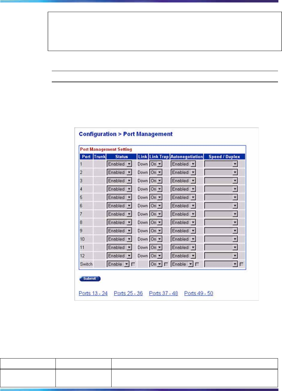
Configuring switch port status 325
ATTENTION
The Autonegotiation,Speed, and the Duplex fields are independent of MultiLink
Trunking, VLANs, and the STP.
To configure switch port properties, use the following procedure:
Step Action
1From the main menu, choose Configuration > Port Management.
The Port Management page appears.
Figure 120
Port Management page
The following table describes the items on the Port Management
page.
Table 144
Port Management page items
Item Range Description
Port The switch port number of the corresponding row. The
values that you set in each switch row affect all switch ports.
Nortel Ethernet Routing Switch 2500 Series
Overview — System Configuration
NN47215-500 (323162-B) 02.02 Standard
4.1 19 November 2007
Copyright © 2007, Nortel Networks
.

326 Configuring the switch using web-based management
Item Range Description
Alias Displays the name, or alias, you assigned the port. To
assign or change the name, enter up to 26 alphanumeric
characters.
Trunk The trunk group that the switch port belongs to as specified
in the Trunk Member fields on the MultiLink Trunk page.
Status (1) Enabled
(2) Disabled Choose to enable or disable the port. You can also use this
field to control access to any switch port.
The default setting is Enabled.
Link The current link state of the corresponding port as follows:
Up: The port is connected and operational
Down: The port is not connected or is not operational.
Link Trap (1) On
(2) Off Choose to control whether link up/down traps are sent to
the configured trap receiver from the switch.
The default setting is On.
Autonegotiation (1) Enabled
(2) Disabled Choose to enable or disable the autonegotiation feature.
Choosing to enable autonegotiation sets the
corresponding port speed to match the best service
provided by the connected station, up to 100Mb/s in
full-duplex mode.
ATTENTION
Autonegotiation also enables auto sensing on 10/100
ports.
The default setting is Enabled.
Speed / Duplex (1) 10Mbs / Half
(2) 10Mbs / Full
(3) 100Mbs / Half
(4) 100Mbs / Full
(5) 1000Mbs / Full
Lets you manually configure any port to support a specific
Ethernet speed and duplex setting.
The default setting is 10 Mbs/Half when autonegotiation is
disabled and 1000 Mb/s full-duplex for gigabit ports only.
2In the port row of your choice, select from the lists.
3Click Submit.
Nortel Ethernet Routing Switch 2500 Series
Overview — System Configuration
NN47215-500 (323162-B) 02.02 Standard
4.1 19 November 2007
Copyright © 2007, Nortel Networks
.
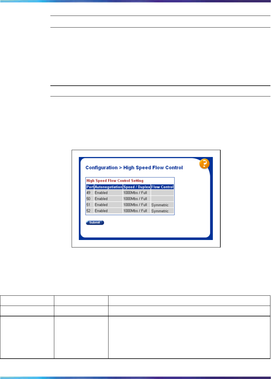
Configuring high speed flow control 327
—End—
Configuring high speed flow control
You can view the High Speed Flow Control parameters for Ethernet Routing
Switch 2500 Series in this page.
To configure high speed flow control, use the following procedure:
Step Action
1From the main menu, choose Configuration > High Speed Flow
Control.
The High Speed Flow Control page appears.
Figure 121
High Speed Flow Control page
The following table describes the items on the High Speed Flow
Control page.
Table 145
High Speed Flow Control page items
Item Range Description
Port The switch port number of the corresponding row.
Autonegotiation (1) Enabled
(2) Disabled Displays if the autonegotiation feature is enabled or
disabled.
When enabled, the port advertises support only for
1000Mb/s operation in full-duplex mode.
Nortel Ethernet Routing Switch 2500 Series
Overview — System Configuration
NN47215-500 (323162-B) 02.02 Standard
4.1 19 November 2007
Copyright © 2007, Nortel Networks
.
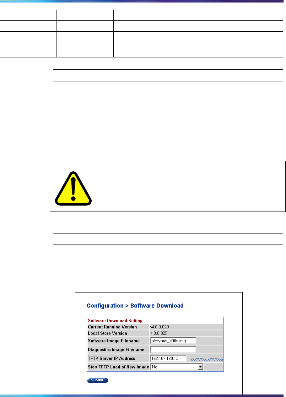
328 Configuring the switch using web-based management
Item Range Description
Speed/Duplex 100MBS/Full XXXXXX
Flow Control (1) Enabled
(2) Symmetric
(3) Asymmetric
Displays current settings of flow control.
—End—
Downloading switch images
You can download the Ethernet Routing Switch 2500 Series software image
to nonvolatile flash memory. To download the Ethernet Routing Switch 2500
Series software image, a properly configured Trivial File Transfer Protocol
(TFTP) server must be present in your network, and the Ethernet Routing
Switch 2500 Series must have an IP address. To learn how to configure the
switch IP address, see "ip address command" (page 178).
CAUTION
Do not interrupt power to the device during the software download
process. A power interruption can corrupt the firmware image.
To download a switch image, use the following procedure:
Step Action
1From the main menu, choose Configuration > Software Download.
The Software Download page appears.
Figure 122
Software Download page
Nortel Ethernet Routing Switch 2500 Series
Overview — System Configuration
NN47215-500 (323162-B) 02.02 Standard
4.1 19 November 2007
Copyright © 2007, Nortel Networks
.

Downloading switch images 329
The following table describes the fields on the Software Download
page.
Table 146
Software Download page fields
Fields Range Description
Current Running Version The version of the current running
software.
Local Store Version The local version of the software in the
flash memory.
Software Image Filename 1..30 Type the software image file name.
Diagnostics Filename 1..30 Type the diagnostics file name.
TFTP Server IP Address XXX.XXX.XXX.XXX Type the IP address of your TFTP load
host.
Download Option No
Software Image
Diagnostics
Software Image If Newer
Download without reset
Choose the software download option.
2Type information in the text boxes, or select from a list.
3Click Submit.
The software download process automatically completes without
user intervention. The process erases the contents of flash memory
and replaces it with a new software image. Take care not to interrupt
the download process until after it runs to completion (the process
can take up to ten minutes, depending on network conditions).
Unless you choose the Download without reset option, the switch
automatically resets after the download process is complete. The
new software image then initiates a self-test.
During the download process, the Ethernet Routing Switch 2500
Series is not operational. You can monitor the progress of the
download process by observing the LED indications.
—End—
The following table describes the LED indications displayed during the
software download process.
Nortel Ethernet Routing Switch 2500 Series
Overview — System Configuration
NN47215-500 (323162-B) 02.02 Standard
4.1 19 November 2007
Copyright © 2007, Nortel Networks
.

330 Configuring the switch using web-based management
ATTENTION
The LED indications described in the following table apply to a 2526T switch
model. Although a 2550T switch provides similar LED indications, the LED
indication sequence is associated within the 48-port range.
Table 147
LED Indications during the software download process
Phase Description LED Indications
1The switch downloads the new
software image and programs it. 100 Mb/s port status LEDs (ports 18 to 24
only): The LEDs begin to turn on in succession
on each ASIC as follows: ASIC 1 from port 1 to
port 12 and return, ASIC 2 from with port 24 to
port 13 and return, ASIC 3 from port 25 to port
36 and return, ASIC 4 from port 48 to port 37
and return.
2The switch resets automatically. After the reset completes, the new software
image initiates the switch self-test, which
comprises various diagnostic routines and
subtests.
ATTENTION
The LEDs display various patterns to indicate
that the subtests are in progress.
Downloading ASCII configuration files
The ASCII Config Download feature lets you upload an ASCII configuration
file from a personal computer to the Ethernet Routing Switch 2500 Series.
In the current implementation, you require a TFTP server to upload an ASCII
configuration file to the Ethernet Routing Switch 2500 Series. But with this
feature the requirement of a TFTP server is eliminated. This feature lets you
upload an ASCII configuration file using the HTTP protocol.
To download the ASCII configuration file to the Ethernet Routing Switch
2500 Series.
Step Action
1From the main menu, choose Configuration > Ascii Config
Download.
2The Ascii Configuration File Download page appears.
Nortel Ethernet Routing Switch 2500 Series
Overview — System Configuration
NN47215-500 (323162-B) 02.02 Standard
4.1 19 November 2007
Copyright © 2007, Nortel Networks
.
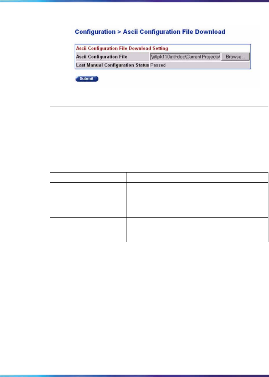
Storing and retrieving a switch configuration file from a TFTP server 331
Figure 123
Ascii Configuration file download page
—End—
The following table describes the items displayed on the ASCII Configuration
File Download page.
Table 148
Ascii Configuration file download page items
Item Description
Ascii Configuration File Lets you select the ASCII config file located on a
personal computer.
Last Manual Configuration
Status Displays the status of the download.
Submit Click on this button to upload the ASCII configuration
file from the personal computer to the Ethernet
Routing Switch 2500 Series.
Storing and retrieving a switch configuration file from a TFTP server
You can store switch configuration parameters on a Trivial File Transfer
Protocol (TFTP) server. You can retrieve the configuration parameters and
use the retrieved parameters to automatically configure a replacement
switch.
To store a switch configuration, you must set up the file on your TFTP server
and set the filename read/write permission to enabled.
To download the Ethernet Routing Switch 2500 Series configuration file, a
properly configured TFTP server must be present in your network, and the
Ethernet Routing Switch 2500 Series must have an IP address.
To learn how to configure the switch IP address, see "Configuring BootP, IP,
and gateway settings" (page 319).
To store or retrieve a switch configuration file, use the following procedure:
Nortel Ethernet Routing Switch 2500 Series
Overview — System Configuration
NN47215-500 (323162-B) 02.02 Standard
4.1 19 November 2007
Copyright © 2007, Nortel Networks
.
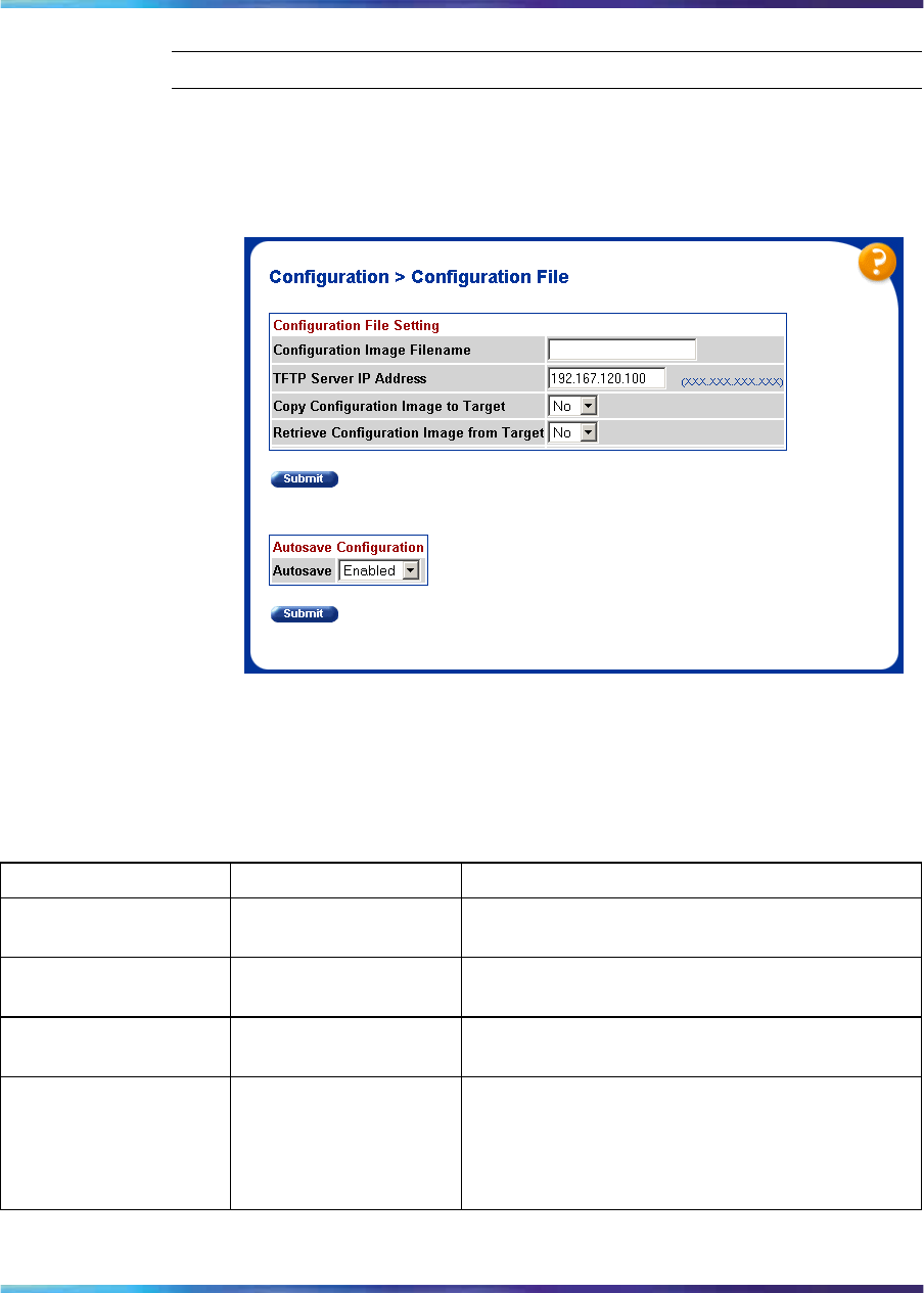
332 Configuring the switch using web-based management
Step Action
1From the main menu, choose Configuration > Configuration File.
The Configuration File page appears.
Figure 124
Configuration File
The following table describes the Configuration File Setting items
on the Configuration File page.
Table 149
Configuration File Setting items
Item Range Description
Configuration Image
Filename 1..32 Type the configuration file name.
TFTP Server IP
Address XXX.XXX.XXX.XXX Type the IP address of the TFTP load host.
Copy Configuration
Image to Target (1) Yes
(2) No Choose whether or not to copy the configuration
image to the server.
Retrieve Configuration
Image from Target (1) Yes
(2) No Choose whether or not to retrieve the
configuration image from a server. If you choose
Yes, the download process begins immediately
and, when completed, causes the switch to reset
with the new configuration parameters.
2Type information in the text boxes, or select from a list.
Nortel Ethernet Routing Switch 2500 Series
Overview — System Configuration
NN47215-500 (323162-B) 02.02 Standard
4.1 19 November 2007
Copyright © 2007, Nortel Networks
.

Enabling and disabling autosave 333
3Click Submit.
—End—
Requirements for storing and retrieving configuration parameters on a
TFTP server
The following requirements apply when storing and retrieving configuration
parameters on a TFTP server:
•The Configuration File feature can only be used to copy standalone
switch configuration parameters to other standalone switches.
•A configuration file obtained from a standalone switch can only be used
to configure other standalone switches that have the same firmware
revision and model type as the donor standalone switch.
•The configuration file also duplicates any settings that exist for any GBIC
that is installed in the donor switch.
•If you use the configuration file to configure another switch that has
the same GBIC model installed, the configuration file settings can also
apply to and override the existing GBIC settings.
Table 150 "Parameters not saved to the configuration file" (page
333) describes the parameters that are not saved to the configuration file.
Table 150
Parameters not saved to the configuration file
These parameters are not saved:
In-Band Switch IP Address
In-Band Subnet Mask
Default Gateway
Configuration Image Filename
TFTP Server IP Address
Enabling and disabling autosave
The Configuration File page also lets you enable and disable the autosave
feature on the switch.
To enable or disable autosave, use the following procedure:
Step Action
1From the main menu, choose Configuration > Configuration File.
The Configuration File page appears.
Nortel Ethernet Routing Switch 2500 Series
Overview — System Configuration
NN47215-500 (323162-B) 02.02 Standard
4.1 19 November 2007
Copyright © 2007, Nortel Networks
.
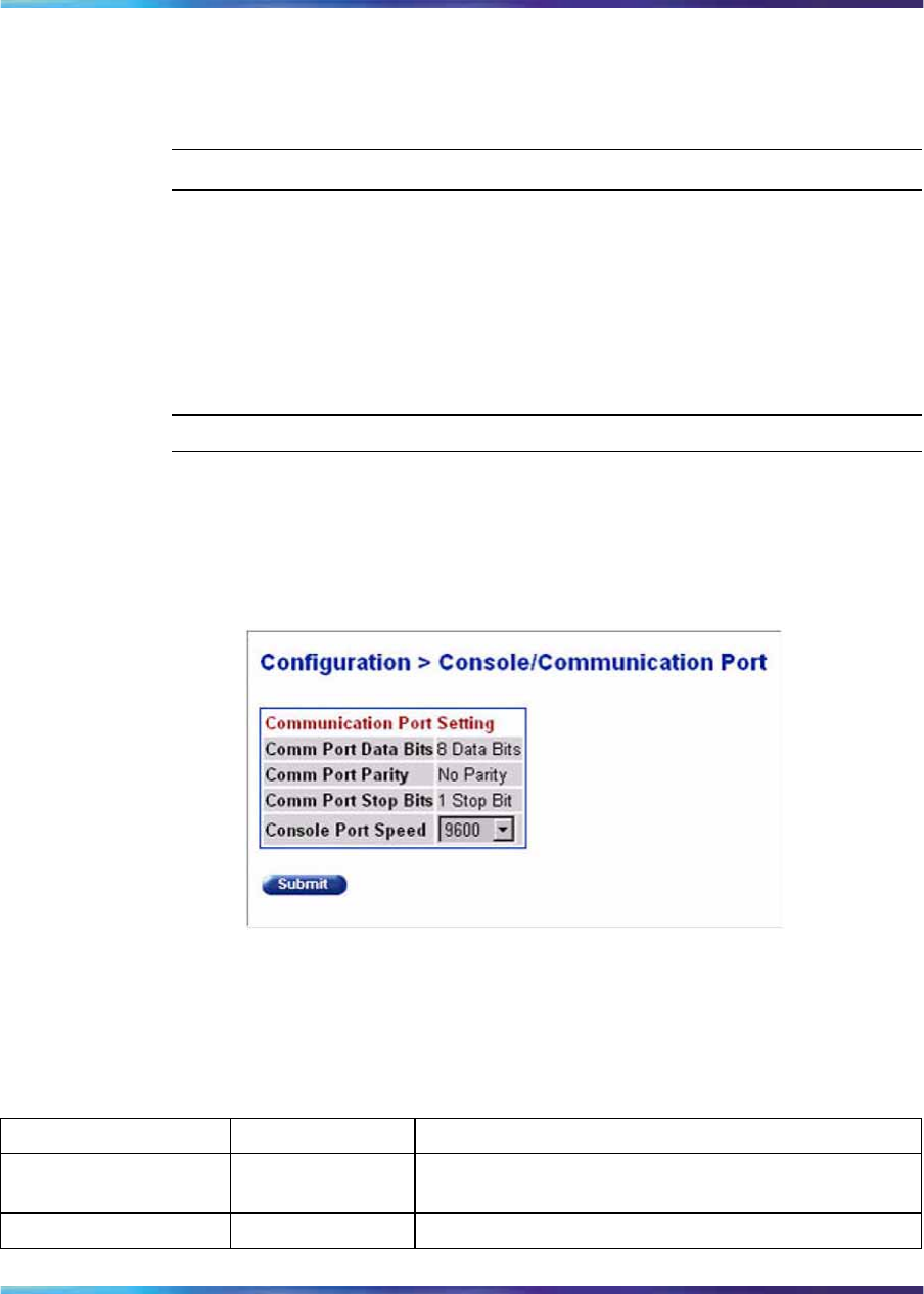
334 Configuring the switch using web-based management
2Under Autosave Configuration, choose Enabled or Disabled from
the drop-down list.
3Click Submit.
—End—
Configuring port communication speed
You can view the current console/communication port settings and configure
the Console port baud rate to match the baud rate of the console terminal.
To view current console/communication port settings and configure Console
port speed, use the following procedure:
Step Action
1From the main menu, choose Configuration > Console/Comm
Port.
The Console/Communication Port page appears.
Figure 125
Console/Communication Port page
The following table describes the items on the Console/Commu-
nication Port page.
Table 151
Console/Communication Port page items
Item Range Description
Comm Port Data Bits The current console communication port data bit
setting.
Comm Port Parity The current console communication port parity setting.
Nortel Ethernet Routing Switch 2500 Series
Overview — System Configuration
NN47215-500 (323162-B) 02.02 Standard
4.1 19 November 2007
Copyright © 2007, Nortel Networks
.
Configuring Rate Limiting 335
Item Range Description
Comm Port Stop Bits The current console communication port stop bit
setting.
Choose the Console port speed baud rate.
ATTENTION
The default setting is 9600.
Console port Speed 2400
4800
9600
19200
38400
CAUTION
If you choose a baud rate that does
not match your console terminal
baud rate, you lose communication
with the configuration interface
when you click Submit.
2Select from the list.
3Click Submit.
—End—
Configuring Rate Limiting
Broadcast Rate Limiting is a box-oriented feature which lets you configure
threshold limits for either broadcast or multicast packets ingressing on a
port for a given time interval (in packets/second). If the configured threshold
exceeds on a port, the switch drops extra packets received. No SNMP trap
or syslog is generated in case of congestion.
Configuring Rate Limiting
To configure Rate Limiting using the web-based management system, use
the following procedure:
Step Action
1From the main menu, choose Application > Rate Limiting.
The Rate Limiting page appears.
Nortel Ethernet Routing Switch 2500 Series
Overview — System Configuration
NN47215-500 (323162-B) 02.02 Standard
4.1 19 November 2007
Copyright © 2007, Nortel Networks
.
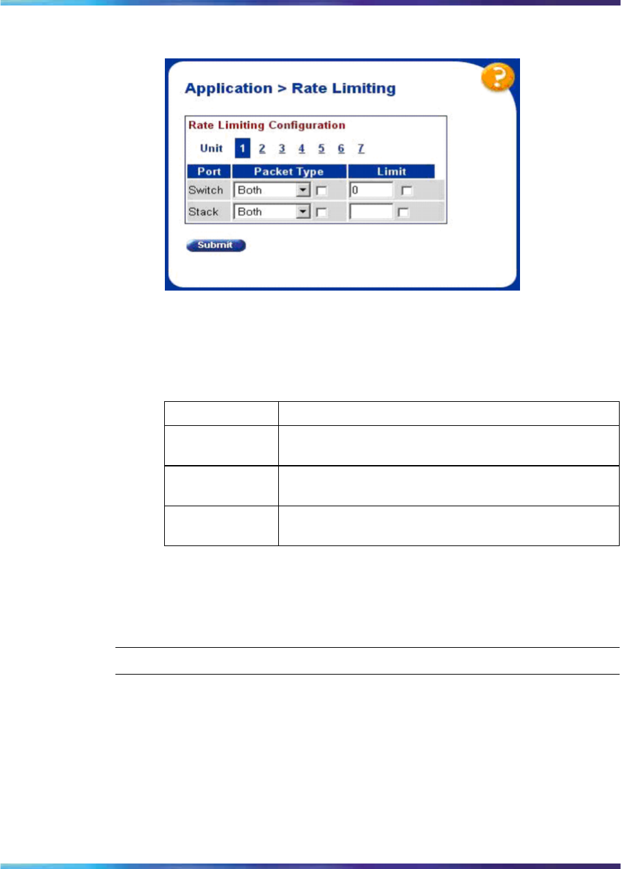
336 Configuring the switch using web-based management
Figure 126
Rate Limiting page
The following table describes the items on the Rate Limiting page.
Table 152
Rate Limiting page items
Section Description
Port The port number that corresponds to the selected
switch or stack.
Packet Type Select the type of packet: Multicast, Broadcast, or
Both.
Limit Configure the threshold limit for the selected type of
packet.
2On the Rate Limiting page, type information in the text boxes, or
select from a list.
3Click Submit.
—End—
Nortel Ethernet Routing Switch 2500 Series
Overview — System Configuration
NN47215-500 (323162-B) 02.02 Standard
4.1 19 November 2007
Copyright © 2007, Nortel Networks
.
337
Troubleshooting
This chapter describes how to isolate and diagnose problems with your
Ethernet Routing Switch 2500 Series and covers the following topics:
•"Interpreting the LEDs" (page 337)
•"Diagnosing and correcting problems" (page 337)
— Normal power-up sequence
— Port connection problems
Interpreting the LEDs
For information on interpreting the LEDs for the Ethernet Routing Switch
2500 Series, see "LED display panel" (page 27).
Diagnosing and correcting problems
Before you execute the problem-solving steps described in this section,
cycle the power to the Ethernet Routing Switch 2500 Series (disconnect and
then reconnect the AC power cord); then verify that the switch follows the
normal power-up sequence.
WARNING
To avoid injury from hazardous electrical current, do not remove
the top cover of the device. There are no user-serviceable
components inside.
WARNING
Vorsicht
Um Verletzungsgefahr durch einen elektrischen Stromschlag
auszuschließen, nehmen Sie niemals die obere Abdeckung vom
Gerät ab. Im Geräteinnern befinden sich keine Komponenten, die
vom Benutzer gewartet werden können.
Nortel Ethernet Routing Switch 2500 Series
Overview — System Configuration
NN47215-500 (323162-B) 02.02 Standard
4.1 19 November 2007
Copyright © 2007, Nortel Networks
.
338 Troubleshooting
WARNING
Avertissement
Pour éviter tout risque d’électrocution, ne jamais retirer le capot
de l’appareil. Cet appareil ne contient aucune pièce accessible
par l’utilisateur.
WARNING
Advertencia
A fin de evitar daños personales por corrientes eléctricas
peligrosas, no desmonte nunca la cubierta superior de este
dispositivo. Los componentes internos no son reparables por el
usuario.
WARNING
Avvertenza
Per evitare lesioni fisiche dovute a scariche pericolose di corrente,
non rimuovere mai il coperchio superiore del dispositivo. I
componenti interni non possono essere manipolati dall’utente.
Normal power-up sequence
In a normal power-up sequence, the LEDs appear as follows:
1. After power is applied to the switch, the Pwr (Power) LED turns on within
5 seconds.
2. The switch initiates a self-test, during which the port LEDs display
various patterns to indicate the progress of the self-test.
3. After the self-test, the remaining port LEDs indicate their operational
status, as described in the following table.
Nortel Ethernet Routing Switch 2500 Series
Overview — System Configuration
NN47215-500 (323162-B) 02.02 Standard
4.1 19 November 2007
Copyright © 2007, Nortel Networks
.

Diagnosing and correcting problems 339
Table 153
Corrective actions
Symptom Probable cause Corrective action
The switch is not
receiving AC power. Verify that the AC power cord is fastened
securely at both ends and that power is available
at the AC power outlet.
All LEDs are off.
The fans are not
operating or the airflow
is blocked, causing the
unit to overheat.
Verify that there is sufficient space for
adequate airflow on both sides of the switch.
ATTENTION
Operating temperature for the switch must
not exceed 40 C (104 F). Do not place the
switch in areas where it can be exposed to
direct sunlight or near warm air exhausts or
heaters.
The switch is
experiencing a port
connection problem.
The Activity LED for a
connected port is off or
does not blink (and you
have reason to believe
that traffic is present). The switch’s link
partner is not
autonegotiating
properly.
See "Port connection problems" (page 339).
Port connection problems
You can usually trace port connection problems to either a poor cable
connection or an improper connection of the port cables at either end of
the link. To remedy these types of problems, make sure that the cable
connections are secure and that the cables connect to the correct ports at
both ends of the link.
Port connection problems are also traceable to the autonegotiation mode
or the port interface.
Autonegotiation modes
Port connection problems can occur when a port (or station) is connected
to another port (or station) that is not operating in a compatible mode (for
example, connecting a full-duplex port on one station to a half-duplex port
on another station).
Nortel Ethernet Routing Switch 2500 Series
Overview — System Configuration
NN47215-500 (323162-B) 02.02 Standard
4.1 19 November 2007
Copyright © 2007, Nortel Networks
.

340 Troubleshooting
The Ethernet Routing Switch 2500 Series negotiates port speeds
according to the IEEE 802.3u autonegotiating standard. The switch adjusts
(autonegotiates) its port speed and duplex mode to match the best service
provided by the connected station, up to 100 Mb/s in full-duplex mode as
follows:
•If the connected station uses a form of autonegotiation that is not
compatible with the IEEE 802.3u autonegotiating standard, the Ethernet
Routing Switch 2500 Series cannot negotiate a compatible mode for
correct operation.
•If the autonegotiation feature is not present or not enabled at the
connected station, the Ethernet Routing Switch 2500 Series may not be
able to determine the correct duplex modes.
In both situations, the Ethernet Routing Switch 2500 Series "autosenses"
the speed of the connected station and, by default, reverts to half-duplex
mode. If the connected station is operating in full-duplex mode, it cannot
communicate with the switch.
To correct this mode mismatch problem, use the following procedure:
1. Use the Port Management page to disable autonegotiation for the
suspect port (see "Configuring switch port status" (page 324)).
2. Manually set the Speed/Duplex field to match the speed/duplex mode
of the connected station.
You may have to try several settings before you find the correct
speed/duplex mode of the connected station.
If the problem persists:
1. Disable the autonegotiation feature at the connected station.
2. Manually set the speed/duplex mode of the connected station to the
same speed/duplex mode you have manually set for the Ethernet
Routing Switch 2500 Series port.
Port interface
Ensure that the devices are connected using the appropriate crossover or
straight-through cable, or that autonegotiation is active.
Nortel Ethernet Routing Switch 2500 Series
Overview — System Configuration
NN47215-500 (323162-B) 02.02 Standard
4.1 19 November 2007
Copyright © 2007, Nortel Networks
.
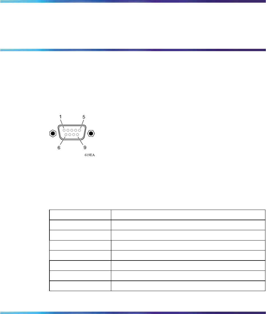
341
Appendix A
DB-9 (RS-232-D) Console/Comm Port
connector
The Console/Comm Port connector is a DB-9, RS-232-D male serial port
connector. You can use this connector to connect a management station or
console terminal to the Ethernet Routing Switch by using a straight-through
DB-9 to DB-9 standard serial port cable.
Figure 127
DB-9 Console port connector
The following table lists the DB-9 Console port connector pin assignments.
Table 154
DB-9 Console port connector pin assignments
Pin number Signal
1Carrier detect (not used)
2Transmit data (TXD)
3Receive data (RXD)
4Data terminal ready (not used)
5Signal ground (GND)
6Not used
7Request to send (not used)
Nortel Ethernet Routing Switch 2500 Series
Overview — System Configuration
NN47215-500 (323162-B) 02.02 Standard
4.1 19 November 2007
Copyright © 2007, Nortel Networks
.

342 Appendix A DB-9 (RS-232-D) Console/Comm Port connector
Pin number Signal
8Not used
9Ring indicator (not used)
Nortel Ethernet Routing Switch 2500 Series
Overview — System Configuration
NN47215-500 (323162-B) 02.02 Standard
4.1 19 November 2007
Copyright © 2007, Nortel Networks
.

343
Appendix B
Default settings
The following table lists the factory default settings for the Ethernet Routing
Switch 2500 Series.
Table 155
Factory default settings
Field Default setting
BootP Request Mode BootP or Default IP
In-Band Switch IP Address 192.168.1.1
In-Band Subnet Mask 255.255.255.0
Default Gateway 0.0.0.0
(no IP address assigned)
Read-Only Community String public
Read-Write Community String private
Trap IP Address 0.0.0.0
(no IP address assigned)
Community String Zero-length string
Autotoplology Enabled
Authentication Trap Enabled
Link Up/Down Trap Enabled
Reset Count 1 (This is the value only when the flash memory
is erased. Even if you reboot the switch to factory
defaults, the Reset Count increases and is equal to the
number of times the switch restarted from the last flash
memory erase.)
Last Reset Type Power Cycle
sysContact Zero-length string
sysName Zero-length string
sysLocation Zero-length string
Nortel Ethernet Routing Switch 2500 Series
Overview — System Configuration
NN47215-500 (323162-B) 02.02 Standard
4.1 19 November 2007
Copyright © 2007, Nortel Networks
.

344 Appendix B Default settings
Field Default setting
Aging Time 300 seconds
Find an Address 00-00-00-00-00-00
(no MAC address assigned)
MAC Address Security Disabled
MAC Address Security SNMP-Locked Disabled
Partition Port on Intrusion Detected Disabled
Partition Time 0 seconds (the value 0 indicates forever)
DA Filtering on Intrusion Detected Disabled
Generate SNMP Trap on Intrusion Disabled
Clear by Ports NONE
Learn by Ports NONE
Current Learning Mode Not Learning
Trunk blank field
Security Disabled
Port List Blank field
Find an Address Blank field
MAC Address Blank field (no address assigned)
Allowed Source Blank field
Display/Create MAC Address 00-00-00-00-00-00
EAPOL Administrative Stat Disabled
Initialize No
Operational Status Authorized
Administrative Traffic Control Incoming and Outgoing
Operational Traffic Control Incoming and Outgoing
Re-authenticate Now No
Re-authentication Enabled
Re-authentication period 3600 seconds
Quiet Period 60 seconds
Transmit Period 30 seconds
Supplicant Timeout 30 seconds
Server Timeout 30 seconds
Maximum Requests 2 attempts
Create VLAN 1
Delete VLAN blank field
Nortel Ethernet Routing Switch 2500 Series
Overview — System Configuration
NN47215-500 (323162-B) 02.02 Standard
4.1 19 November 2007
Copyright © 2007, Nortel Networks
.

Appendix B Default settings 345
Field Default setting
VLAN Name VLAN # (VLAN number)
Management VLAN Yes, VLAN #1
VLAN State Inactive
Port Membership Default (all ports assigned as untagged members of
VLAN 1)
Unit 1
Port 1
Filter Untagged Frames No
Port Name Unit 1, Port 1
PVID 1
Tagging Untagged Access
Unit 1
Port 1
PVID 1 (read only)
Port Name Unit 1, Port 1 (read only)
Unit 1
Status Enabled (for all ports)
LnkTrap On
Autonegotiation Enabled (for all ports)
Speed/Duplex 100Mbs/Half (when Autonegotiation is Disabled)
Autonegotiation Enabled
Speed/Duplex 100Mbs/Half (when Autonegotiation is Disabled)
Flow Control Disabled
Trunk 1 to 6 (depending on configuration status)
Trunk Members (Unit/Port) Blank field
STP Learning Normal
Trunk Mode Basic
Trunk Status Disabled
Trunk Name Trunk #1 to Trunk #6
Traffic Type Rx and Tx
Monitoring Mode Disabled
Monitor/Unit Port Zero-length string
Unit/Port X Zero-length string
Limit 0 pps
Nortel Ethernet Routing Switch 2500 Series
Overview — System Configuration
NN47215-500 (323162-B) 02.02 Standard
4.1 19 November 2007
Copyright © 2007, Nortel Networks
.

346 Appendix B Default settings
Field Default setting
Packet Type Both
Snooping Disabled
VLAN 1
Proxy Disabled
Robust Value 2
Query Time 125 seconds
Set Router Ports Version 1
Static Router Ports Blank
Unit 1
Port 1
Display Messages From Volatile
Display configuration complete? No
Clear Messages From None
Console Port Speed 9600 Baud
Console Switch Password Not Required
TELNET/WEB Switch Password Type None
TELNET Password Type None
Console Read-Only Switch Password
(standard software image)
user
Console Read-Write Switch Password
(standard software image)
secure
Console Read-Only Switch Password
(secure software image) userpasswd
Console Read-Write Switch Password
(secure software image) securepasswd
Primary RADIUS Server 0.0.0.0
Secondary RADIUS Server 0.0.0.0
RADIUS UDP Port 1812
RADIUS Shared Secret Null String
RADIUS Timeout 2 seconds.
STP Mode IEEE 802.1s
Bridge Priority 8000 in Hex.
Bridge Hello Time 2 seconds
Bridge Max. Age Time 20 seconds
Bridge Forward Delay Time 15 seconds
Nortel Ethernet Routing Switch 2500 Series
Overview — System Configuration
NN47215-500 (323162-B) 02.02 Standard
4.1 19 November 2007
Copyright © 2007, Nortel Networks
.

Appendix B Default settings 347
Field Default setting
Bridge Max. Age Time 20 seconds
Bridge Forward Delay Time 15 seconds
Participation Normal Learning
Priority 128
Path Cost 10 or 100
State Topology dependent
Bridge Priority 0x0000 - 0xF000
Root Path Cost 0
Maximum Age Time 20 seconds
Forward Delay 15 seconds
Bridge Maximum Age Time 15 seconds
Bridge Priority 0x8000
Bridge Hello Time 20 seconds
Bridge Max. Age Time 20 seconds
Bridge Forward Delay Time 15 seconds
Default Path Cost Type •32 bits in MSTP/RSTP mode
•16 bits in legacy STP mode
•Not supported in STPG mode
Priority 128
Path Cost 10 or 100 (1 for Gigabit port) Path Cost = 1000/LAN
speed (in Mb/s)
Bridge Priority 0x8000
Root Port 0
Root Path Cost 0
Maximum Age Time 20 seconds
Forward Delay 15 seconds
Bridge Hello Time 20 seconds
Bridge Max. Age Time 20 seconds
Bridge Forward Delay Time 15 seconds
Bridge Priority 0x8000
Bridge Hello Time 2 seconds
Bridge Maximum Age Time 20 seconds
Bridge Forward Delay Time 15 seconds
Add VLAN membership 1
Nortel Ethernet Routing Switch 2500 Series
Overview — System Configuration
NN47215-500 (323162-B) 02.02 Standard
4.1 19 November 2007
Copyright © 2007, Nortel Networks
.

348 Appendix B Default settings
Field Default setting
Delete VLAN Membership Blank
STP Group State Active for CIST; InActive for MSTIs 2 to 7.
Participation Normal Learning
Priority 128
Path Cost 200000 (20 000 for Gigabit port) Path Cost =
2*1010/(Number of Kilobits/link)
State Topology dependent
Bridge Priority HEX: 0x0000 - 0xF000
Bridge Priority HEX: 0x0000 - 0xF000
Root Port 0
Root Path Cost 0
Maximum Age Time 20 seconds
Forward Delay 15 seconds
Bridge Forward Delay 15 seconds
Tx Hold Count 3
Hop Count (Max) 2000
Default Path Cost Type •32 bits in MSTP/RSTP mode
•16 bits in legacy STP802.1d mode
•Not supported in STP802.1d mode
Region Name MAC address of the device
TELNET Access Enabled
SNMP Access Enabled
Web Access Enabled, Yes
Login Timeout 1 minute
Login Retries 3
Inactivity Timeout 15 minutes
Event Logging All
First field: 0.0.0.0
(no IP address assigned)
Allowed Source IP Address
(10 user-configurable fields) Remaining nine fields:
255.255.255.255
First field: 0.0.0.0
(no IP address assigned)
Allowed Source Mask
(10 user-configurable fields) Remaining nine fields:
255.255.255.255
Nortel Ethernet Routing Switch 2500 Series
Overview — System Configuration
NN47215-500 (323162-B) 02.02 Standard
4.1 19 November 2007
Copyright © 2007, Nortel Networks
.

Appendix B Default settings 349
Field Default setting
Image Filename Zero-length string
Diagnostics Filename Zero-length string
TFTP Server IP Address 0.0.0.0
(no IP address assigned)
Start TFTP Load of New Image No
Configuration Image Filename Zero-length string
TFTP Server IP Address 0.0.0.0
(no IP address assigned)
Copy Configuration Image to Server No
Retrieve Configuration Image from Server No
ASCII Configuration Filename Zero-length string
TFTP Server IP Address 0.0.0.0
Retrieve Configuration File from Server No
Last Manual Configuration Status Passed
Last Auto Configuration Status Passed
Auto Configuration on Reset Disabled
Operational Mode of rear ports (for
pre-enabled units) Stacking Mode
Operational Mode of rear ports (for non
pre-enabled units) Standalone Mode
Nortel Ethernet Routing Switch 2500 Series
Overview — System Configuration
NN47215-500 (323162-B) 02.02 Standard
4.1 19 November 2007
Copyright © 2007, Nortel Networks
.

350 Appendix B Default settings
Nortel Ethernet Routing Switch 2500 Series
Overview — System Configuration
NN47215-500 (323162-B) 02.02 Standard
4.1 19 November 2007
Copyright © 2007, Nortel Networks
.
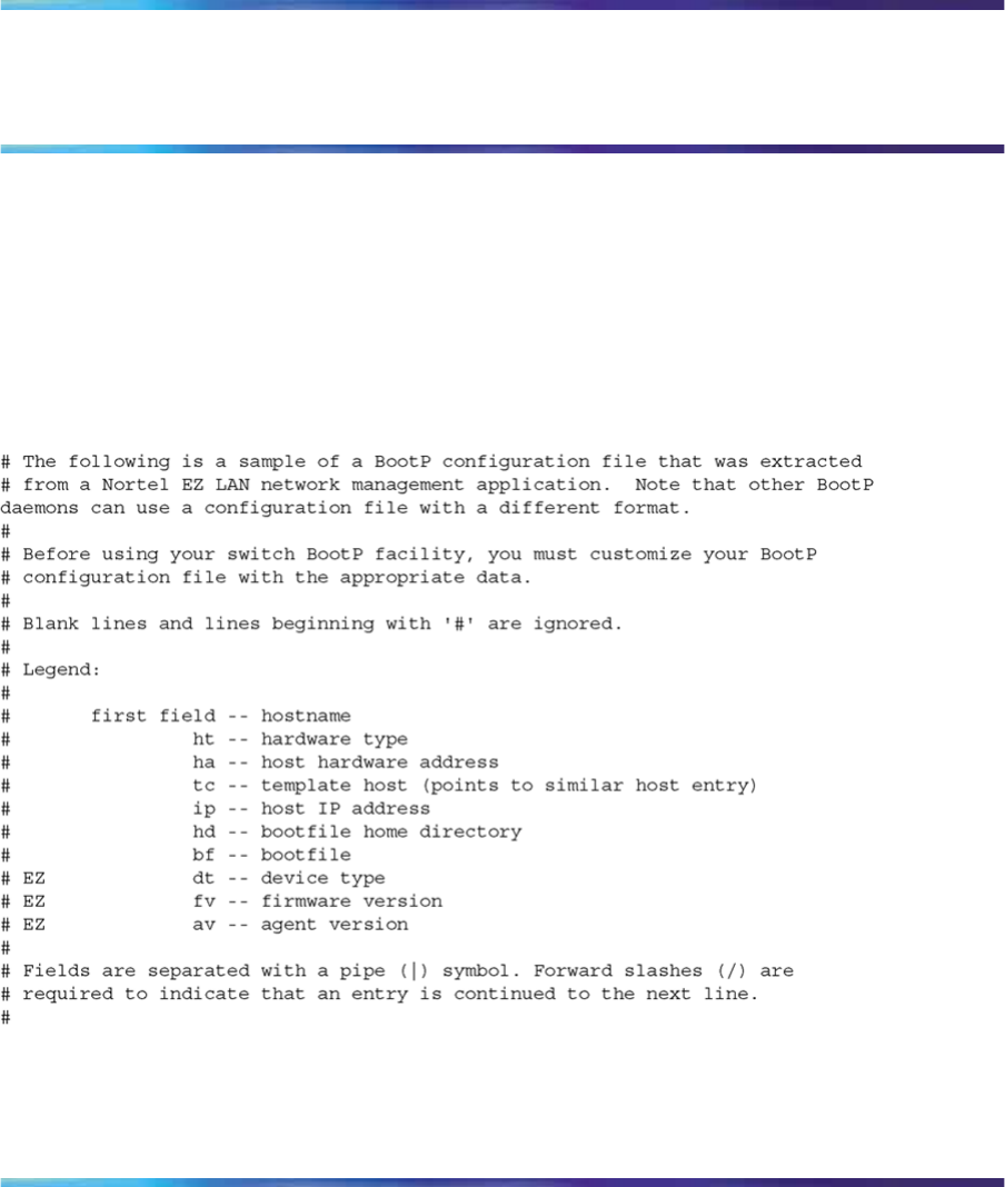
351
Appendix C
Sample BootP configuration file
This appendix provides a sample BootP configuration file. The BootP server
searches for this file, called bootptab (or BOOTPTAB.TXT, depending
on your operating system), which contains the site-specific information
(including IP addresses) needed to perform the software download and
configuration. You can modify this sample BootP configuration file or create
one of your own.
A sample BootP configuration file follows:
Nortel Ethernet Routing Switch 2500 Series
Overview — System Configuration
NN47215-500 (323162-B) 02.02 Standard
4.1 19 November 2007
Copyright © 2007, Nortel Networks
.
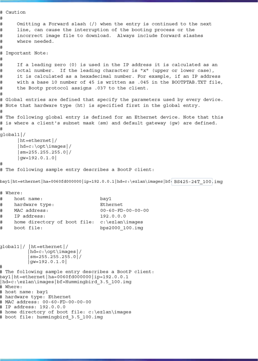
352 Appendix C Sample BootP configuration file
Nortel Ethernet Routing Switch 2500 Series
Overview — System Configuration
NN47215-500 (323162-B) 02.02 Standard
4.1 19 November 2007
Copyright © 2007, Nortel Networks
.

353
Appendix D
Command List
This appendix provides the complete CLI command list in alphabetical
order, with approximate page references for the beginning pages of further
explanations.
ATTENTION
This information is presented for reference only and must not be considered
to be an exact representation.
Table 156
CLI command list
Command Page No.
auto-negotiation-advertisements [port <portlist>]
[10-full] [10-half] [100-full] [100-half] [1000-full]
[asymm-pause-frame] [pause-frame] [none]
"auto-negotiation-advertisements command"
(page 246)
auto-pvid Nortel Ethernet Routing Switch 2500 Series
Configuration — VLANs, Spanning Tree, and
MultiLink Trunking (NN47215-501)
autotopology "autotopology command" (page 216)
autosave enable "autosave enable command" (page 207)
banner [ custom | static | disabled | <1-19> LINE ] "banner command for displaying banner" (page
201)
blink-leds [off | time <1-10>] "Configuring LEDs to blink on the display panel"
(page 229)
boot [default] "boot command" (page 196)
clear logging [nv | nonvolatile | volatile] Nortel Ethernet Routing Switch 2500 Series
Performance Management — System Monitoring
(NN47215-502)
clear-stats [port<portlist>] Nortel Ethernet Routing Switch 2500 Series
Performance Management — System Monitoring
(NN47215-502)
Nortel Ethernet Routing Switch 2500 Series
Overview — System Configuration
NN47215-500 (323162-B) 02.02 Standard
4.1 19 November 2007
Copyright © 2007, Nortel Networks
.

354 Appendix D Command List
Command Page No.
cli password {read-only|read-write} <WORD>
cli password {serial|telnet} {none|local|radius}
Nortel Ethernet Routing Switch 2500 Series
Security — Configuration and Management
(NN47215-505)
clock summer-time <zone> [date {<day>
<month> <year> <hh:mm>} {<day> <month>
<year> <hh:mm>}] [<offset>]
"clock summer-time" (page 213)
clock time-zone <zone> <hours> <minutes> "clock time-zone" (page 213)
configure {terminal|network} "configure command" (page 91)
configure network [load-on-boot {disable|use-
bootp|use-config}]
configure network [filename <FILENAME>]
configure network [address <XXX.XXX.XXX.
XXX>]
"Configuration Management" (page 188)
configure command "configure command" (page 91)
copy config nvram "copy config nvram command" (page 205)
copy config tftp [address <XXX.XXX.XXX.XXX>]
filename <WORD> "copy config tftp command" (page 199)
copy tftp config [address <XXX.XXX.XXX.XXX>]
filename <WORD> "copy tftp config command" (page 200)
copy running-config tftp {<IP Address>
<filename>} "copy running-config tftp command" (page 192)
default auto-negotiation-advertisements [port
<portlist>] "default auto-negotiation-advertisements
command" (page 247)
default autotopology "default autotopology command" (page 216)
default autosave enable "default autosave enable command" (page 207)
default command "default command" (page 90)
default duplex [port <portlist>] "default duplex command" (page 239)
default eapol guest-vlan Nortel Ethernet Routing Switch 2500 Series
Security — Configuration and Management
(NN47215-505)
default flowcontrol [port <portlist>] "default flowcontrol command" (page 242)
default http-port Nortel Ethernet Routing Switch 2500 Series
Security — Configuration and Management
(NN47215-505)
default ip address "default ip address command" (page 179)
default ip bootp server "default ip bootp server command" (page 197)
Nortel Ethernet Routing Switch 2500 Series
Overview — System Configuration
NN47215-500 (323162-B) 02.02 Standard
4.1 19 November 2007
Copyright © 2007, Nortel Networks
.

Appendix D Command List 355
Command Page No.
default ip default-gateway "default ip default-gateway command" (page 181)
default ip domain-name "default ip domain-name command" (page 188)
default ip netmask "default ip netmask command" (page 179)
default lacp aggregation [port <portlist>] enable Nortel Ethernet Routing Switch 2500 Series
Configuration — VLANs, Spanning Tree, and
MultiLink Trunking (NN47215-501)
default lacp key [port <portlist>] Nortel Ethernet Routing Switch 2500 Series
Configuration — VLANs, Spanning Tree, and
MultiLink Trunking (NN47215-501)
default lacp mode [port <portlist>] Nortel Ethernet Routing Switch 2500 Series
Configuration — VLANs, Spanning Tree, and
MultiLink Trunking (NN47215-501)
default lacp priority [port <portlist>] Nortel Ethernet Routing Switch 2500 Series
Configuration — VLANs, Spanning Tree, and
MultiLink Trunking (NN47215-501)
default lacp system-priority Nortel Ethernet Routing Switch 2500 Series
Configuration — VLANs, Spanning Tree, and
MultiLink Trunking (NN47215-501)
default lacp timeout-time [port <portlist>] Nortel Ethernet Routing Switch 2500 Series
Configuration — VLANs, Spanning Tree, and
MultiLink Trunking (NN47215-501)
default lldp [port <portlist>] config-notification "default lldp config-notification command" (page
220)
default lldp [port <portlist>] status "default lldp status command" (page 223)
default lldp [tx-interval] [tx-hold-multiplier]
[reinit-delay] [tx-delay] [notification-interval] "default lldp command" (page 219)
default lldp tx-tlv [port <portlist>]
[local-mgmt-addr] [port-desc] [sys-cap]
[sys-desc] [sys-name]
"default lldp tx-tlv command" (page 222)
default logging Nortel Ethernet Routing Switch 2500 Series
Performance Management — System Monitoring
(NN47215-502)
default logging remote level Nortel Ethernet Routing Switch 2500 Series
Performance Management — System Monitoring
(NN47215-502)
default mac-address-table aging-time "default mac-address-table aging-time command"
(page 99)
default name [port <port.ist>] "default name command" (page 236)
default qos egressmap Nortel Ethernet Routing Switch 2500
Series Configuration — Quality of Service
(NN47215-504)
Nortel Ethernet Routing Switch 2500 Series
Overview — System Configuration
NN47215-500 (323162-B) 02.02 Standard
4.1 19 November 2007
Copyright © 2007, Nortel Networks
.

356 Appendix D Command List
Command Page No.
default radius-server [host | key | password | port
| secondary-host | timeout]
Nortel Ethernet Routing Switch 2500 Series
Security — Configuration and Management
(NN47215-505)
default rate-limit "default rate-limit command" (page 244)
default snmp-server authentication-trap Nortel Ethernet Routing Switch 2500 Series
Security — Configuration and Management
(NN47215-505)
default snmp-server community [ro|rw] Nortel Ethernet Routing Switch 2500 Series
Security — Configuration and Management
(NN47215-505)
default snmp-server contact Nortel Ethernet Routing Switch 2500 Series
Security — Configuration and Management
(NN47215-505)
default snmp-server host Nortel Ethernet Routing Switch 2500 Series
Security — Configuration and Management
(NN47215-505)
default snmp-server location Nortel Ethernet Routing Switch 2500 Series
Security — Configuration and Management
(NN47215-505)
default snmp-server name Nortel Ethernet Routing Switch 2500 Series
Security — Configuration and Management
(NN47215-505)
default snmp trap link-status [port <portlist>] Nortel Ethernet Routing Switch 2500 Series
Security — Configuration and Management
(NN47215-505)
default sntp [enable | server | sync-interval] "default sntp command" (page 212)
default spanning-tree [port <portlist>] [learning]
[cost] [priority] Nortel Ethernet Routing Switch 2500 Series
Configuration — VLANs, Spanning Tree, and
MultiLink Trunking (NN47215-501)
default speed [port <portlist>] "default speed command" (page 238)
default ssh [dsa-auth|pass-auth|port|timeout] Nortel Ethernet Routing Switch 2500 Series
Security — Configuration and Management
(NN47215-505)
default telnet-access Nortel Ethernet Routing Switch 2500 Series
Security — Configuration and Management
(NN47215-505)
default tftp-server "default tftp-server command" (page 199)
default vlan configcontrol Nortel Ethernet Routing Switch 2500 Series
Configuration — VLANs, Spanning Tree, and
MultiLink Trunking (NN47215-501)
Nortel Ethernet Routing Switch 2500 Series
Overview — System Configuration
NN47215-500 (323162-B) 02.02 Standard
4.1 19 November 2007
Copyright © 2007, Nortel Networks
.

Appendix D Command List 357
Command Page No.
default vlan igmp <1-4094> Nortel Ethernet Routing Switch 2500 Series
Configuration — IP Multicast (NN47215-503)
default vlan mgmt Nortel Ethernet Routing Switch 2500 Series
Configuration — VLANs, Spanning Tree, and
MultiLink Trunking (NN47215-501)
disable "disable command" (page 92)
download [address <ip>] {image <image-name>|
image-if-newer <image-name> | diag
<filename>} [no-reset]
"download command" (page 230)
duplex [port <portlist>] {full|half|auto} "speed command" (page 237)
eapol {disable|enable} Nortel Ethernet Routing Switch 2500 Series
Security — Configuration and Management
(NN47215-505)
eapol guest-vlan [vid <1-4094> | enable] Nortel Ethernet Routing Switch 2500 Series
Security — Configuration and Management
(NN47215-505)
eapol [port <portlist>] [init] [status
authorized|unauthorized|auto] [traffic-control
in-out|in] [re-authentication enable|disable]
[re-authentication-period <1-604800>]
[re-authenticate] [quiet-interval <num>]
[transmit-interval <num>] [supplicant-timeout
<num>] [server-timeout <num>][max-request
<num>]
Nortel Ethernet Routing Switch 2500 Series
Security — Configuration and Management
(NN47215-505)
enable command "enable command" (page 91)
Enabling CANA "Enabling Custom Autonegotiation
Advertisements (CANA)" (page 244)
end command "end command" (page 92)
exit "exit command" (page 92)
flowcontrol [port <portlist>] {asymmetric|
symmetrid|auto|disable}
"Enabling flow control" (page 240)
help "help command" (page 89)
http-port <1024-65535> Nortel Ethernet Routing Switch 2500 Series
Security — Configuration and Management
(NN47215-505)
interface FastEthernet {<portlist>} "interface command" (page 91)
ip address <XXX.XXX.XXX.XXX> [netmask
<XXX.XXX.XXX.XXX>] "ip address command" (page 178)
ip bootp server {last|needed|disable|always} "ip bootp server command" (page 196)
ip domain-name [<LINE>] "ip domain-name command" (page 187)
Nortel Ethernet Routing Switch 2500 Series
Overview — System Configuration
NN47215-500 (323162-B) 02.02 Standard
4.1 19 November 2007
Copyright © 2007, Nortel Networks
.

358 Appendix D Command List
Command Page No.
ip default-gateway <XXX.XXX.XXX.XXX> "ip default-gateway command" (page 180)
ip name-server <A.B.C.D> "ip name-server command" (page 186)
ipmgr {source-ip <1-10> <XXX.XXX.XXX.XXX
>[mask <XXX.XXX.XXX.XXX>]} Nortel Ethernet Routing Switch 2500 Series
Security — Configuration and Management
(NN47215-505)
ipmgr {telnet|snmp|http} [source-ip
<1-10> <XXX.XXX.XXX.XXX> [mask
<XXX.XXX.XXX.XXX>]]
Nortel Ethernet Routing Switch 2500 Series
Security — Configuration and Management
(NN47215-505)
lacp aggregation [port <portlist>] enable Nortel Ethernet Routing Switch 2500 Series
Configuration — VLANs, Spanning Tree, and
MultiLink Trunking (NN47215-501)
lacp clear-stats [ port <WORD>] Nortel Ethernet Routing Switch 2500 Series
Configuration — VLANs, Spanning Tree, and
MultiLink Trunking (NN47215-501)
lacp key [port <portlist>] <1-4095> Nortel Ethernet Routing Switch 2500 Series
Configuration — VLANs, Spanning Tree, and
MultiLink Trunking (NN47215-501)
lacp mode [port <portlist>] {off | passive | active} Nortel Ethernet Routing Switch 2500 Series
Configuration — VLANs, Spanning Tree, and
MultiLink Trunking (NN47215-501)
lacp priority [port <portlist>] <0-255> Nortel Ethernet Routing Switch 2500 Series
Configuration — VLANs, Spanning Tree, and
MultiLink Trunking (NN47215-501)
lacp system-priority [0-65535] Nortel Ethernet Routing Switch 2500 Series
Configuration — VLANs, Spanning Tree, and
MultiLink Trunking (NN47215-501)
lacp timeout-time [port <portlist>] {short | long} Nortel Ethernet Routing Switch 2500 Series
Configuration — VLANs, Spanning Tree, and
MultiLink Trunking (NN47215-501)
lldp [port <portlist>] config-notification "lldp config-notification command" (page 219)
lldp [port <portlist>] status [rxOnly | txAndRx |
txOnly] "lldp status command" (page 222)
lldp [tx-interval <5-32768>] [tx-hold-multiplier
<2-10>] [reinit-delay <1-10>] [tx-delay <1-8192>]
[notification-interval <5-3600>]
"lldp command" (page 218)
lldp tx-tlv [port <portlist>] [local-mgmt-addr]
[port-desc] [sys-cap] [sys-desc] [sys-name] "lldp tx-tlv command" (page 221)
logging [enable|disable] [level crit
ical|serious|informational] [nv-level
critical|serious|informational|none]
Nortel Ethernet Routing Switch 2500 Series
Performance Management — System Monitoring
(NN47215-502)
Nortel Ethernet Routing Switch 2500 Series
Overview — System Configuration
NN47215-500 (323162-B) 02.02 Standard
4.1 19 November 2007
Copyright © 2007, Nortel Networks
.

Appendix D Command List 359
Command Page No.
logging remote address <A.B.C.D> Nortel Ethernet Routing Switch 2500 Series
Performance Management — System Monitoring
(NN47215-502)
logging remote enable Nortel Ethernet Routing Switch 2500 Series
Performance Management — System Monitoring
(NN47215-502)
logging remote level {critical|informational|
serious|none}
Nortel Ethernet Routing Switch 2500 Series
Performance Management — System Monitoring
(NN47215-502)
logout "logout command" (page 90)
mac-address-table aging-time <time> "mac-address-table aging-time command" (page
99)
mac-security [disable|enable] [filtering
{enable|disable}] [intrusion-detect
{enable|disable|forever}] [intrusion-timer
<1-65535>] [learning-ports <portlist> [add
<portlist> | [remove <portlist>]]] [learning
{enable|disable}]|mac-address-table|mac-da-f
ilter|security list [snmp-lock {enable|disable}]
[snmp-trap {enable|disable}]
Nortel Ethernet Routing Switch 2500 Series
Security — Configuration and Management
(NN47215-505)
mac-security [port <portlist>] {disable|enable|
learning}
Nortel Ethernet Routing Switch 2500 Series
Security — Configuration and Management
(NN47215-505)
mac-security mac-address-table address
<H.H.H.> {port <portlist>|security-list <1-32>} Nortel Ethernet Routing Switch 2500 Series
Security — Configuration and Management
(NN47215-505)
mac-security mac-da-filter {add <H.H.H.> |
delete <H.H.H.>}
Nortel Ethernet Routing Switch 2500 Series
Security — Configuration and Management
(NN47215-505)
mac-security security-list <1-32> [add <portlist>]
[remove <portlist>] [<portlist>] Nortel Ethernet Routing Switch 2500 Series
Security — Configuration and Management
(NN47215-505)
mlt <id> [name <trunkname>] [enable|disable]
[member <portlist>][learning {disable|fast|norm
al}] [bpdu{all-ports|single-port}]
Nortel Ethernet Routing Switch 2500 Series
Configuration — VLANs, Spanning Tree, and
MultiLink Trunking (NN47215-501)
name [port <portlist>] <LINE> "name command" (page 235)
no auto-pvid Nortel Ethernet Routing Switch 2500 Series
Configuration — VLANs, Spanning Tree, and
MultiLink Trunking (NN47215-501)
no auto-negotiation-advertisements [port
<portlist>] "no auto-negotiation-advertisements command"
(page 247)
no autosave enable "no autosave enable command" (page 207)
Nortel Ethernet Routing Switch 2500 Series
Overview — System Configuration
NN47215-500 (323162-B) 02.02 Standard
4.1 19 November 2007
Copyright © 2007, Nortel Networks
.

360 Appendix D Command List
Command Page No.
no autotopology "no autotopology command" (page 216)
no-banner "no banner command" (page 202)
no clock summer-time "no clock summer-time" (page 214)
no clock time-zone "no clock time-zone" (page 213)
no command "no command" (page 90)
no eapol guest-vlan [enable] Nortel Ethernet Routing Switch 2500 Series
Security — Configuration and Management
(NN47215-505)
no flowcontrol [port <portlist>] "no autotopology command" (page 216)
no ip address "no ip address command" (page 179)
no ip bootp server "no ip bootp server command" (page 197)
no ip default-gateway "no ip default-gateway command" (page 180)
no ip domain-name "no ip domain-name command" (page 188)
no ip name-server <A.B.C.D> "no ip name-server command" (page 187)
no ip netmask "no ip netmask command" (page 179)
no ipmgr {source-ip [<1-10>]} Nortel Ethernet Routing Switch 2500 Series
Security — Configuration and Management
(NN47215-505)
no ipmgr {telnet|snmp|web} Nortel Ethernet Routing Switch 2500 Series
Security — Configuration and Management
(NN47215-505)
no lacp aggregation [port <portlist>] enable Nortel Ethernet Routing Switch 2500 Series
Configuration — VLANs, Spanning Tree, and
MultiLink Trunking (NN47215-501)
no lldp [port <portlist>] config-notification "no lldp config-notification command" (page 220)
no lldp [port <portlist>] status "no lldp status command" (page 223)
no lldp tx-tlv [port <portlist>] [local-mgmt-addr]
[port-desc] [sys-cap] [sys-desc] [sys-name] "no lldp tx-tlv command" (page 221)
no logging Nortel Ethernet Routing Switch 2500 Series
Performance Management — System Monitoring
(NN47215-502)
no logging remote address Nortel Ethernet Routing Switch 2500 Series
Performance Management — System Monitoring
(NN47215-502)
no logging remote enable Nortel Ethernet Routing Switch 2500 Series
Performance Management — System Monitoring
(NN47215-502)
Nortel Ethernet Routing Switch 2500 Series
Overview — System Configuration
NN47215-500 (323162-B) 02.02 Standard
4.1 19 November 2007
Copyright © 2007, Nortel Networks
.

Appendix D Command List 361
Command Page No.
no logging remote level Nortel Ethernet Routing Switch 2500 Series
Performance Management — System Monitoring
(NN47215-502)
no mac-security Nortel Ethernet Routing Switch 2500 Series
Security — Configuration and Management
(NN47215-505)
no mac-security mac-address-table {address
<H.H.H>|port <portlist>|security-list <1-32>] Nortel Ethernet Routing Switch 2500 Series
Security — Configuration and Management
(NN47215-505)
no mac-security security-list <1-32> Nortel Ethernet Routing Switch 2500 Series
Security — Configuration and Management
(NN47215-505)
no mlt [<id>] Nortel Ethernet Routing Switch 2500 Series
Configuration — VLANs, Spanning Tree, and
MultiLink Trunking (NN47215-501)
no name [port <portlist>] "no name command" (page 236)
no password security Nortel Ethernet Routing Switch 2500 Series
Security — Configuration and Management
(NN47215-505)
no port-mirroring Nortel Ethernet Routing Switch 2500 Series
Performance Management — System Monitoring
(NN47215-502)
no radius-server [host] [key] [password fallback]
[secondary host] Nortel Ethernet Routing Switch 2500 Series
Security — Configuration and Management
(NN47215-505)
no rate-limit "no rate-limit command" (page 244)
no rmon alarm [<1-65535>] Nortel Ethernet Routing Switch 2500 Series
Performance Management — System Monitoring
(NN47215-502)
no rmon event [<1-65535>] Nortel Ethernet Routing Switch 2500 Series
Performance Management — System Monitoring
(NN47215-502)
no rmon history [<1-65535>] Nortel Ethernet Routing Switch 2500 Series
Performance Management — System Monitoring
(NN47215-502)
no rmon stats [<1-65535>] Nortel Ethernet Routing Switch 2500 Series
Performance Management — System Monitoring
(NN47215-502)
no shutdown [port <portlist>] "no shutdown command" (page 234)
Nortel Ethernet Routing Switch 2500 Series
Overview — System Configuration
NN47215-500 (323162-B) 02.02 Standard
4.1 19 November 2007
Copyright © 2007, Nortel Networks
.

362 Appendix D Command List
Command Page No.
no snmp server [authentication-trap | community
[ro |rw | <community-string>] |contact |host
[<host-ip> [port <1-65535>] [v1 | v2c | v3|
<community-string>]] | location| name | user
[engine-id <snmpEngineID>] <User id>|view
<view name>]
Nortel Ethernet Routing Switch 2500 Series
Security — Configuration and Management
(NN47215-505)
no snmp-server Nortel Ethernet Routing Switch 2500 Series
Security — Configuration and Management
(NN47215-505)
no snmp-server authentication-trap Nortel Ethernet Routing Switch 2500 Series
Security — Configuration and Management
(NN47215-505)
no snmp-server community [ro | rw |
<community-string> ]
Nortel Ethernet Routing Switch 2500 Series
Security — Configuration and Management
(NN47215-505)
no snmp-server contact Nortel Ethernet Routing Switch 2500 Series
Security — Configuration and Management
(NN47215-505)
no snmp-server host <host-ip> {v1|v2c|v3} Nortel Ethernet Routing Switch 2500 Series
Security — Configuration and Management
(NN47215-505)
no snmp-server location <text> Nortel Ethernet Routing Switch 2500 Series
Security — Configuration and Management
(NN47215-505)
no snmp-server name <text> Nortel Ethernet Routing Switch 2500 Series
Security — Configuration and Management
(NN47215-505)
no snmp-server user [engine-id <engineid>]
<username> Nortel Ethernet Routing Switch 2500 Series
Security — Configuration and Management
(NN47215-505)
no snmp-server view <viewname> Nortel Ethernet Routing Switch 2500 Series
Security — Configuration and Management
(NN47215-505)
no snmp trap link-status [port <portlist>] Nortel Ethernet Routing Switch 2500 Series
Security — Configuration and Management
(NN47215-505)
no ssh Nortel Ethernet Routing Switch 2500 Series
Security — Configuration and Management
(NN47215-505)
no ssh dsa-auth Nortel Ethernet Routing Switch 2500 Series
Security — Configuration and Management
(NN47215-505)
Nortel Ethernet Routing Switch 2500 Series
Overview — System Configuration
NN47215-500 (323162-B) 02.02 Standard
4.1 19 November 2007
Copyright © 2007, Nortel Networks
.

Appendix D Command List 363
Command Page No.
no ssh dsa-auth-key Nortel Ethernet Routing Switch 2500 Series
Security — Configuration and Management
(NN47215-505)
no ssh dsa-host-key Nortel Ethernet Routing Switch 2500 Series
Security — Configuration and Management
(NN47215-505)
no ssh pass-auth Nortel Ethernet Routing Switch 2500 Series
Security — Configuration and Management
(NN47215-505)
no sntp enable "no sntp enable command" (page 209)
no sntp server <primary|secondary> "no sntp server command" (page 210)
no spanning-tree mstp msti <1 - 7> [port
<portlist>] Nortel Ethernet Routing Switch 2500 Series
Configuration — VLANs, Spanning Tree, and
MultiLink Trunking (NN47215-501)
no spanning-tree [port <portlist>] Nortel Ethernet Routing Switch 2500 Series
Configuration — VLANs, Spanning Tree, and
MultiLink Trunking (NN47215-501)
no telnet-access [source-ip [<1-10>]] Nortel Ethernet Routing Switch 2500 Series
Security — Configuration and Management
(NN47215-505)
no tftp-server "no tftp-server command" (page 199)
no vlan <1-4094> Nortel Ethernet Routing Switch 2500 Series
Configuration — VLANs, Spanning Tree, and
MultiLink Trunking (NN47215-501)
no web-server Nortel Ethernet Routing Switch 2500 Series
Security — Configuration and Management
(NN47215-505)
password aging-time day <1-2730> Nortel Ethernet Routing Switch 2500 Series
Security — Configuration and Management
(NN47215-505)
password security Nortel Ethernet Routing Switch 2500 Series
Security — Configuration and Management
(NN47215-505)
ping <A.B.C.D or Hostname> "ping command" (page 183)
ping <XXX.XXX.XXX.XXX> [datasize
<64-4096>] [{count <1-9999>} | continuous]
[{timeout | -t} <1-120>] [interval <1-60>] [debug]
"ping command" (page 183)
port-mirroring mode {disable | Xrx | Xtx |
XrxOrXtx} monitor-port <portlist> mirror-port-X
<portlist>
Nortel Ethernet Routing Switch 2500 Series
Performance Management — System Monitoring
(NN47215-502)
Nortel Ethernet Routing Switch 2500 Series
Overview — System Configuration
NN47215-500 (323162-B) 02.02 Standard
4.1 19 November 2007
Copyright © 2007, Nortel Networks
.

364 Appendix D Command List
Command Page No.
qos egressmap ds <0-63> 1p <0-7> Nortel Ethernet Routing Switch 2500
Series Configuration — Quality of Service
(NN47215-504)
qos egressmap enable Nortel Ethernet Routing Switch 2500
Series Configuration — Quality of Service
(NN47215-504)
radius-server host <address> [secondary-host
<address>] port <num> key <string> [timeout
<1-60>]
Nortel Ethernet Routing Switch 2500 Series
Security — Configuration and Management
(NN47215-505)
radius-server password fallback Nortel Ethernet Routing Switch 2500 Series
Security — Configuration and Management
(NN47215-505)
rate-limit {multicast <pct>| broadcast <pct>| both
<pct>}
"rate-limit command" (page 243)
reload [force] [minutes-to-wait <1-60>] [cancel] "reload command" (page 93)
restore factory-default [ -y ] "Resetting the switch to default configuration"
(page 184)
rmon alarm <1-65535> <WORD> <1-214
7483647> {absolute|delta} rising-threshold
<-2147483648-2147483647> [<1-65535>]
falling-threshold <-2147483648-2147483647>
[<1-65535>] [owner <LINE>]
Nortel Ethernet Routing Switch 2500 Series
Performance Management — System Monitoring
(NN47215-502)
rmon event <1-65535> [log] [trap] [description
<LINE>] [owner <LINE>] Nortel Ethernet Routing Switch 2500 Series
Performance Management — System Monitoring
(NN47215-502)
rmon history <1-65535> <LINE> <1-65535>
<1-3600> [owner <LINE>] Nortel Ethernet Routing Switch 2500 Series
Performance Management — System Monitoring
(NN47215-502)
rmon stats <1-65535> <port> [owner <LINE>] Nortel Ethernet Routing Switch 2500 Series
Performance Management — System Monitoring
(NN47215-502)
save config "save config command" (page 206)
show arp-table "Displaying the ARP table" (page 202)
show auto-negotiation-advertisements [port
<portlist>] "Enabling Custom Autonegotiation
Advertisements (CANA)" (page 244)
show auto-negotiation-capabilities [port
<portlist>] "show auto-negotiation-capabilities command"
(page 245)
show auto-pvid Nortel Ethernet Routing Switch 2500 Series
Configuration — VLANs, Spanning Tree, and
MultiLink Trunking (NN47215-501)
show autosave "show autosave command" (page 206)
Nortel Ethernet Routing Switch 2500 Series
Overview — System Configuration
NN47215-500 (323162-B) 02.02 Standard
4.1 19 November 2007
Copyright © 2007, Nortel Networks
.

Appendix D Command List 365
Command Page No.
show autotopology nmm-table "show autotopology nmm-table" (page 217)
show autotopology settings "show autotopology settings" (page 216)
show banner [ custom | static ] "show banner command" (page 201)
show config-network "show config-network command" (page 190)
show cli {info | mode | password [type]} "show cli command" (page 194)
show clock summer-time "show clock summer-time" (page 215)
show clock time-zone "show clock time-zone" (page 214)
show eapol Nortel Ethernet Routing Switch 2500 Series
Security — Configuration and Management
(NN47215-505)
show eapol guest-vlan [interface < portlist>] Nortel Ethernet Routing Switch 2500 Series
Security — Configuration and Management
(NN47215-505)
show http-port Nortel Ethernet Routing Switch 2500 Series
Security — Configuration and Management
(NN47215-505)
show interfaces [names] [<portlist>] "show interfaces command" (page 202)
show interface FastEthernet eapol [auth-diags
[portlist] | auth-stats [portlist]] Nortel Ethernet Routing Switch 2500 Series
Security — Configuration and Management
(NN47215-505)
show interfaces [gbic-info [<portlist>] | <portlist>
[config] | names [<portlist>]]
"show interfaces command" (page 202)
show interfaces [<portlist>] config "show interfaces config command" (page 204)
show ip address "show ip address command" (page 182)
show ip [bootp] [default-gateway] "show ip command" (page 181)
show ip dns "show ip dns command" (page 185)
show ipmgr Nortel Ethernet Routing Switch 2500 Series
Security — Configuration and Management
(NN47215-505)
show lacp aggr <1-65535> Nortel Ethernet Routing Switch 2500 Series
Configuration — VLANs, Spanning Tree, and
MultiLink Trunking (NN47215-501)
show lacp debug member [portlist] Nortel Ethernet Routing Switch 2500 Series
Configuration — VLANs, Spanning Tree, and
MultiLink Trunking (NN47215-501)
show lacp port [<portlist>] Nortel Ethernet Routing Switch 2500 Series
Configuration — VLANs, Spanning Tree, and
MultiLink Trunking (NN47215-501)
Nortel Ethernet Routing Switch 2500 Series
Overview — System Configuration
NN47215-500 (323162-B) 02.02 Standard
4.1 19 November 2007
Copyright © 2007, Nortel Networks
.

366 Appendix D Command List
Command Page No.
show lacp stats [port <portlist>] Nortel Ethernet Routing Switch 2500 Series
Configuration — VLANs, Spanning Tree, and
MultiLink Trunking (NN47215-501)
show lacp system Nortel Ethernet Routing Switch 2500 Series
Configuration — VLANs, Spanning Tree, and
MultiLink Trunking (NN47215-501)
show lldp [local-sys-data] [mgmt-sys-data] [stats] "show lldp command" (page 224)
show lldp [port <portlist>] [neighbor]
[neighbor-mgmt-addr] [rx-stats] [tx-stats] [tx-tlv] "show lldp port command" (page 226)
show logging [config] [critical] [informational]
[serious] [sort-reverse] Nortel Ethernet Routing Switch 2500 Series
Performance Management — System Monitoring
(NN47215-502)
show mac-address-table [vid <1-4094>]
[aging-time] [address <H.H.H>] [port <LINE>]
[include/exclude <pattern>]
"show mac-address-table command" (page 98)
show mac-security {config|mac-address-table
[address <macaddr>]|port|security-lists|mac-
da-filter}
Nortel Ethernet Routing Switch 2500 Series
Security — Configuration and Management
(NN47215-505)
show mlt [utilization <1-6>] Nortel Ethernet Routing Switch 2500 Series
Configuration — VLANs, Spanning Tree, and
MultiLink Trunking (NN47215-501)
show password [aging-time day | security] Nortel Ethernet Routing Switch 2500 Series
Security — Configuration and Management
(NN47215-505)
show poe-main-status "show poe-main-status command" (page 164)
show poe-port-status "show poe-port-status command" (page 165)
show poe-power-measurement "show poe-power-measurement command"
(page 166)
show port-mirroring Nortel Ethernet Routing Switch 2500 Series
Performance Management — System Monitoring
(NN47215-502)
show port-statistics [port <portlist>] Nortel Ethernet Routing Switch 2500 Series
Performance Management — System Monitoring
(NN47215-502)
show qos egressmap ds <0-63> Nortel Ethernet Routing Switch 2500
Series Configuration — Quality of Service
(NN47215-504)
show qos egressmap status Nortel Ethernet Routing Switch 2500
Series Configuration — Quality of Service
(NN47215-504)
Nortel Ethernet Routing Switch 2500 Series
Overview — System Configuration
NN47215-500 (323162-B) 02.02 Standard
4.1 19 November 2007
Copyright © 2007, Nortel Networks
.

Appendix D Command List 367
Command Page No.
show radius-server Nortel Ethernet Routing Switch 2500 Series
Security — Configuration and Management
(NN47215-505)
show rate-limit "show rate-limit command" (page 243)
show rmon alarm Nortel Ethernet Routing Switch 2500 Series
Performance Management — System Monitoring
(NN47215-502)
show rmon event Nortel Ethernet Routing Switch 2500 Series
Performance Management — System Monitoring
(NN47215-502)
show rmon history Nortel Ethernet Routing Switch 2500 Series
Performance Management — System Monitoring
(NN47215-502)
show rmon stats Nortel Ethernet Routing Switch 2500 Series
Performance Management — System Monitoring
(NN47215-502)
show running-config "show running-config command" (page 191)
show snmp-server community Nortel Ethernet Routing Switch 2500 Series
Security — Configuration and Management
(NN47215-505)
show sntp "show sntp command" (page 208)
show spanning-tree {config [ port [< portlist>] |
cost-calc-mode | op-mode | port [< portlist>]} Nortel Ethernet Routing Switch 2500 Series
Configuration — VLANs, Spanning Tree, and
MultiLink Trunking (NN47215-501)
show spanning-tree mstp config Nortel Ethernet Routing Switch 2500 Series
Configuration — VLANs, Spanning Tree, and
MultiLink Trunking (NN47215-501)
show spanning-tree mstp msti config
<1-7> Nortel Ethernet Routing Switch 2500 Series
Configuration — VLANs, Spanning Tree, and
MultiLink Trunking (NN47215-501)
show spanning-tree mstp msti port config
<1 - 7> [<portlist>] Nortel Ethernet Routing Switch 2500 Series
Configuration — VLANs, Spanning Tree, and
MultiLink Trunking (NN47215-501)
show spanning-tree mstp msti port statistics
<1 - 7> [<portlist>] Nortel Ethernet Routing Switch 2500 Series
Configuration — VLANs, Spanning Tree, and
MultiLink Trunking (NN47215-501)
show spanning-tree mstp msti statistics <1 - 7> Nortel Ethernet Routing Switch 2500 Series
Configuration — VLANs, Spanning Tree, and
MultiLink Trunking (NN47215-501)
show spanning-tree mstp port config [<portlist>] Nortel Ethernet Routing Switch 2500 Series
Configuration — VLANs, Spanning Tree, and
MultiLink Trunking (NN47215-501)
Nortel Ethernet Routing Switch 2500 Series
Overview — System Configuration
NN47215-500 (323162-B) 02.02 Standard
4.1 19 November 2007
Copyright © 2007, Nortel Networks
.

368 Appendix D Command List
Command Page No.
show spanning-tree mstp port statistics
[<portlist>] Nortel Ethernet Routing Switch 2500 Series
Configuration — VLANs, Spanning Tree, and
MultiLink Trunking (NN47215-501)
show spanning-tree mstp statistics Nortel Ethernet Routing Switch 2500 Series
Configuration — VLANs, Spanning Tree, and
MultiLink Trunking (NN47215-501)
show spanning-tree mstp status Nortel Ethernet Routing Switch 2500 Series
Configuration — VLANs, Spanning Tree, and
MultiLink Trunking (NN47215-501)
show spanning-tree rstp config Nortel Ethernet Routing Switch 2500 Series
Configuration — VLANs, Spanning Tree, and
MultiLink Trunking (NN47215-501)
show spanning-tree rstp port config [<portlist>] Nortel Ethernet Routing Switch 2500 Series
Configuration — VLANs, Spanning Tree, and
MultiLink Trunking (NN47215-501)
show spanning-tree rstp port statistics [<portlist>] Nortel Ethernet Routing Switch 2500 Series
Configuration — VLANs, Spanning Tree, and
MultiLink Trunking (NN47215-501)
show spanning-tree rstp port status [<portlist>] Nortel Ethernet Routing Switch 2500 Series
Configuration — VLANs, Spanning Tree, and
MultiLink Trunking (NN47215-501)
show spanning-tree rstp statistics Nortel Ethernet Routing Switch 2500 Series
Configuration — VLANs, Spanning Tree, and
MultiLink Trunking (NN47215-501)
show spanning-tree rstp status Nortel Ethernet Routing Switch 2500 Series
Configuration — VLANs, Spanning Tree, and
MultiLink Trunking (NN47215-501)
show ssh download-auth-key Nortel Ethernet Routing Switch 2500 Series
Security — Configuration and Management
(NN47215-505)
show ssh global Nortel Ethernet Routing Switch 2500 Series
Security — Configuration and Management
(NN47215-505)
show ssh session Nortel Ethernet Routing Switch 2500 Series
Security — Configuration and Management
(NN47215-505)
show sys-info "show sys-info command" (page 96)
show tech "show tech command" (page 97)
show telnet-access Nortel Ethernet Routing Switch 2500 Series
Security — Configuration and Management
(NN47215-505)
show terminal "show terminal command" (page 193)
Nortel Ethernet Routing Switch 2500 Series
Overview — System Configuration
NN47215-500 (323162-B) 02.02 Standard
4.1 19 November 2007
Copyright © 2007, Nortel Networks
.

Appendix D Command List 369
Command Page No.
show tftp-server "show tftp-server command" (page 198)
show vlan configcontrol Nortel Ethernet Routing Switch 2500 Series
Configuration — VLANs, Spanning Tree, and
MultiLink Trunking (NN47215-501)
show vlan igmp <1-4094> Nortel Ethernet Routing Switch 2500 Series
Configuration — IP Multicast (NN47215-503)
show vlan interface info [<portlist>] Nortel Ethernet Routing Switch 2500 Series
Configuration — VLANs, Spanning Tree, and
MultiLink Trunking (NN47215-501)
show vlan interface vids [<portlist>] Nortel Ethernet Routing Switch 2500 Series
Configuration — VLANs, Spanning Tree, and
MultiLink Trunking (NN47215-501)
show vlan multicast membership <1-4094> Nortel Ethernet Routing Switch 2500 Series
Configuration — IP Multicast (NN47215-503)
show vlan vid <1-4094> Nortel Ethernet Routing Switch 2500 Series
Configuration — VLANs, Spanning Tree, and
MultiLink Trunking (NN47215-501)
shutdown [force] [minutes-to-wait <1-60>]
[cancel] "shutdown command" (page 94)
shutdown [port <portlist>] "shutdown command for the port" (page 233)
snmp-server {enable|disable} Nortel Ethernet Routing Switch 2500 Series
Security — Configuration and Management
(NN47215-505)
snmp-server authentication-trap {enable
|disable} Nortel Ethernet Routing Switch 2500 Series
Security — Configuration and Management
(NN47215-505)
snmp-server bootstrap <minimum-secure> |
<semi-secure> |<very-secure>
Nortel Ethernet Routing Switch 2500 Series
Security — Configuration and Management
(NN47215-505)
snmp-server community <community-string>
[ro|rw] Nortel Ethernet Routing Switch 2500 Series
Security — Configuration and Management
(NN47215-505)
snmp-server community <community-string>
{read-view <view-name>|write-view
<view-name>|
notify-view <view-name>}
Nortel Ethernet Routing Switch 2500 Series
Security — Configuration and Management
(NN47215-505)
snmp-server contact <text> Nortel Ethernet Routing Switch 2500 Series
Security — Configuration and Management
(NN47215-505)
Nortel Ethernet Routing Switch 2500 Series
Overview — System Configuration
NN47215-500 (323162-B) 02.02 Standard
4.1 19 November 2007
Copyright © 2007, Nortel Networks
.

370 Appendix D Command List
Command Page No.
snmp-server host <host-ip> [port <1-65535>]
{<community-string>|v2c <community-string>|
v3 {auth|no-auth|auth-priv} <username>}
Nortel Ethernet Routing Switch 2500 Series
Security — Configuration and Management
(NN47215-505)
snmp-server location <text> Nortel Ethernet Routing Switch 2500 Series
Security — Configuration and Management
(NN47215-505)
snmp-server name <text> Nortel Ethernet Routing Switch 2500 Series
Security — Configuration and Management
(NN47215-505)
snmp-server user [engine-id <engineid>]
<username> [read-view <view-name>]
[write-view <view-name>] [notify-view
<view-name>]
[{md5|sha} <password>[read-view <view-name>]
[write-view <view-name>][notify-view
<view-name>]
[{3des|aes|des} <password> [read-view
<view-name>]
[write-view <view-name>][notify-view
<view-name>]
Nortel Ethernet Routing Switch 2500 Series
Security — Configuration and Management
(NN47215-505)
snmp-server view <view-name> <OID> [<OID>
[<OID> [<OID> [<OID> [<OID> [<OID> [<OID>
[<OID> [<OID>]]]]]]]]]
Nortel Ethernet Routing Switch 2500 Series
Security — Configuration and Management
(NN47215-505)
snmp trap link-status [port <portlist>] Nortel Ethernet Routing Switch 2500 Series
Security — Configuration and Management
(NN47215-505)
sntp enable "sntp enable command" (page 209)
sntp server primary address <A.B.C.D> "sntp server primary address command" (page
209)
sntp server secondary address <A.B.C.D> "sntp server secondary address command" (page
210)
sntp sync-interval <0-168> "sntp sync-interval command" (page 211)
sntp sync-now "sntp sync-now command" (page 211)
Nortel Ethernet Routing Switch 2500 Series
Overview — System Configuration
NN47215-500 (323162-B) 02.02 Standard
4.1 19 November 2007
Copyright © 2007, Nortel Networks
.

Appendix D Command List 371
Command Page No.
spanning-tree mstp [max-hop <100 - 4000>]
[forward-time <4 - 30>] [max-age <6 - 40>]
[pathcost-type {bits16 | bits32}][priority
{0000 | 10000 | 20000 | É | F0000}] [tx-hold
count <1 - 10>] [version {stp-compatible
| rstp| mstp}] [add-vlan <1-4094>]
[remove-vlan <1-4094>] [msti <1-7>] [region
{config-id-sel|region-name|region-version}]
Nortel Ethernet Routing Switch 2500 Series
Configuration — VLANs, Spanning Tree, and
MultiLink Trunking (NN47215-501)
spanning-tree mstp msti <1 - 7> [port
<portlist>]enable Nortel Ethernet Routing Switch 2500 Series
Configuration — VLANs, Spanning Tree, and
MultiLink Trunking (NN47215-501)
spanning-tree mstp msti <1 - 7> [port
<portlist>]disable Nortel Ethernet Routing Switch 2500 Series
Configuration — VLANs, Spanning Tree, and
MultiLink Trunking (NN47215-501)
spanning-tree mstp msti <1 - 7> [port <portlist>]
[cost <1 - 200000000>][learning {disable |
enable}][priority {00 | 10 | É | F0}]
Nortel Ethernet Routing Switch 2500 Series
Configuration — VLANs, Spanning Tree, and
MultiLink Trunking (NN47215-501)
spanning-tree mstp msti<1 - 7>[priority{0000
|1000|É|F000}] [add-vlan <vid>][remove-vlan
<vid>][enable]
Nortel Ethernet Routing Switch 2500 Series
Configuration — VLANs, Spanning Tree, and
MultiLink Trunking (NN47215-501)
spanning-tree mstp [port <portlist>] [cost <1 -
200000000>][edge-port {false | true}][hello-time
<1 - 10>] [learning {disable | enable}][p2p {auto |
force-false | force-true}][priority {00 | 10 | É | F0}]
[protocol-migration {false | true}]
Nortel Ethernet Routing Switch 2500 Series
Configuration — VLANs, Spanning Tree, and
MultiLink Trunking (NN47215-501)
spanning-tree mstp region [config-id-sell
<0 - 255>] [region-name <1 - 32
chars>][region-version <0 - 65535>]
Nortel Ethernet Routing Switch 2500 Series
Configuration — VLANs, Spanning Tree, and
MultiLink Trunking (NN47215-501)
spanning-tree [port <portlist>] [learning
{disable|normal|fast}] [cost <1-65535>] [priority
<0-255>]
Nortel Ethernet Routing Switch 2500 Series
Configuration — VLANs, Spanning Tree, and
MultiLink Trunking (NN47215-501)
spanning-tree rstp[forward-time<4 - 30>]
[hello-time <1 - 10>][max-age <6 - 40>]
[pathcost-type{ bits16 | bits32}] [priority{0000|10
000|20000| É| F0000}] [tx-holdcount<1 - 10>]
[version stp-compatible|rstp}]
Nortel Ethernet Routing Switch 2500 Series
Configuration — VLANs, Spanning Tree, and
MultiLink Trunking (NN47215-501)
spanning-tree rstp [port <portlist>] [cost
<1 - 200000000>] [edge-port {false | true}]
[learning {disable | enable}] [p2p {auto |
force-false | force-true}][priority {00 | 10 | É | F0}]
[protocol-migration {false | true}]
Nortel Ethernet Routing Switch 2500 Series
Configuration — VLANs, Spanning Tree, and
MultiLink Trunking (NN47215-501)
Nortel Ethernet Routing Switch 2500 Series
Overview — System Configuration
NN47215-500 (323162-B) 02.02 Standard
4.1 19 November 2007
Copyright © 2007, Nortel Networks
.

372 Appendix D Command List
Command Page No.
speed [port <portlist>] {10|100|1000|auto} "speed command" (page 237)
ssh Nortel Ethernet Routing Switch 2500 Series
Security — Configuration and Management
(NN47215-505)
ssh download-auth-key [address <XXX.XXX.XX
X.XXX>] [key-name <file>] Nortel Ethernet Routing Switch 2500 Series
Security — Configuration and Management
(NN47215-505)
ssh dsa-auth Nortel Ethernet Routing Switch 2500 Series
Security — Configuration and Management
(NN47215-505)
ssh dsa-host-key Nortel Ethernet Routing Switch 2500 Series
Security — Configuration and Management
(NN47215-505)
ssh pass-auth Nortel Ethernet Routing Switch 2500 Series
Security — Configuration and Management
(NN47215-505)
ssh port <1-65535> Nortel Ethernet Routing Switch 2500 Series
Security — Configuration and Management
(NN47215-505)
ssh secure [force] Nortel Ethernet Routing Switch 2500 Series
Security — Configuration and Management
(NN47215-505)
ssh timeout <1-120> Nortel Ethernet Routing Switch 2500 Series
Security — Configuration and Management
(NN47215-505)
telnet-access [enable|disable] [login-timeout
<1-10>] [retry <1-100>] [inactive-timeout <0-60>]
[logging {none|access|failures|all}]
[source-ip <1-10> <XXX.XXX.XXX.XXX> [mask
<XXX.XXX.XXX.XXX>]]
Nortel Ethernet Routing Switch 2500 Series
Security — Configuration and Management
(NN47215-505)
terminal speed {2400|4800|9600|19200|38400}|
length <1-132>|width <1-132>
"terminal command" (page 193)
tftp-server <XXX.XXX.XXX.XXX> "tftp-server command" (page 198)
username <username> <password> [ro|rw] Nortel Ethernet Routing Switch 2500 Series
Security — Configuration and Management
(NN47215-505)
vlan configcontrol <vcc_option> Nortel Ethernet Routing Switch 2500 Series
Configuration — VLANs, Spanning Tree, and
MultiLink Trunking (NN47215-501)
Nortel Ethernet Routing Switch 2500 Series
Overview — System Configuration
NN47215-500 (323162-B) 02.02 Standard
4.1 19 November 2007
Copyright © 2007, Nortel Networks
.

Appendix D Command List 373
Command Page No.
vlan create <1-4094> Nortel Ethernet Routing Switch 2500 Series
Configuration — VLANs, Spanning Tree, and
MultiLink Trunking (NN47215-501)
vlan delete <1-4094> Nortel Ethernet Routing Switch 2500 Series
Configuration — VLANs, Spanning Tree, and
MultiLink Trunking (NN47215-501)
vlan igmp {<1-4094> [snooping {enable|disable}]
[proxy {enable|disable}] [robust-value <value>]
[query-interval <time>] [v1-members <portlist>]
[v2-members <portlist>]
Nortel Ethernet Routing Switch 2500 Series
Configuration — IP Multicast (NN47215-503)
vlan members [add|remove] <1-4094> <portlist> Nortel Ethernet Routing Switch 2500 Series
Configuration — VLANs, Spanning Tree, and
MultiLink Trunking (NN47215-501)
vlan mgmt <1-4094> Nortel Ethernet Routing Switch 2500 Series
Configuration — VLANs, Spanning Tree, and
MultiLink Trunking (NN47215-501)
vlan name <1-4094> <line> Nortel Ethernet Routing Switch 2500 Series
Configuration — VLANs, Spanning Tree, and
MultiLink Trunking (NN47215-501)
vlan ports [<portlist>] [tagging {enable|disable
|tagAll|untagAll|tagPvidOnly| untagPvidOnly}]
[pvid <1-4094>] [remarking {enable|disable}]
[filter-unregistered-frames {enable|disable}]
[filter-untagged-frame {enable|disable}] [priority
<0-7>] [name <line>]
Nortel Ethernet Routing Switch 2500 Series
Configuration — VLANs, Spanning Tree, and
MultiLink Trunking (NN47215-501)
web-server{enable|disable} Nortel Ethernet Routing Switch 2500 Series
Security — Configuration and Management
(NN47215-505)
write memory "write memory command" (page 205)
Nortel Ethernet Routing Switch 2500 Series
Overview — System Configuration
NN47215-500 (323162-B) 02.02 Standard
4.1 19 November 2007
Copyright © 2007, Nortel Networks
.

374 Appendix D Command List
Nortel Ethernet Routing Switch 2500 Series
Overview — System Configuration
NN47215-500 (323162-B) 02.02 Standard
4.1 19 November 2007
Copyright © 2007, Nortel Networks
.
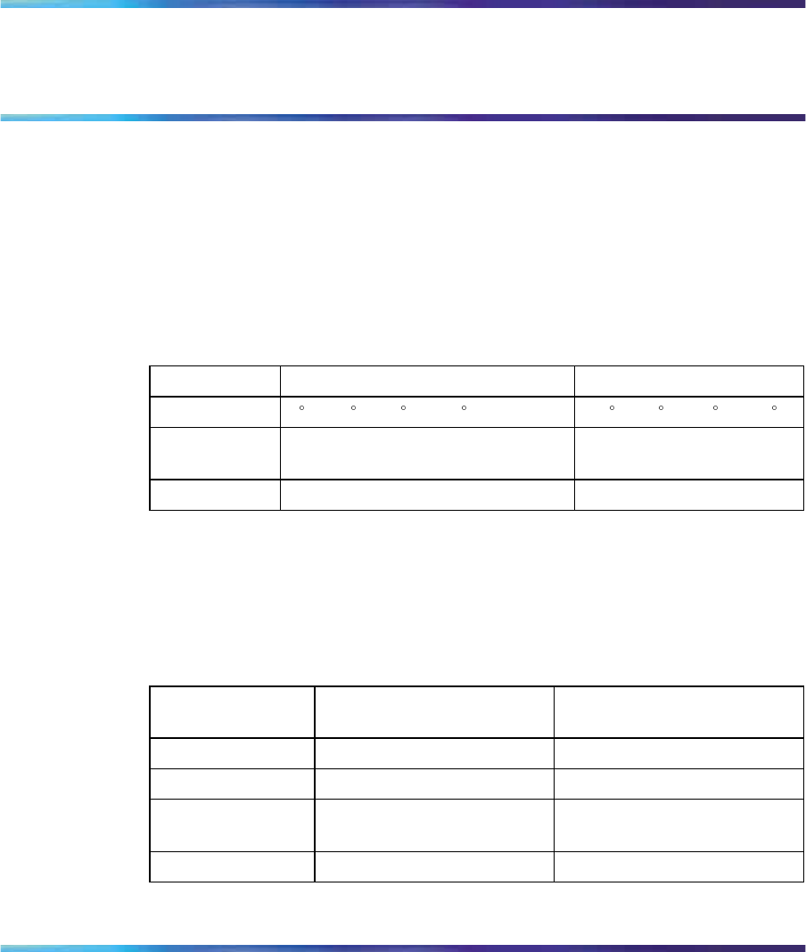
375
Appendix E
Technical specifications
This appendix provides technical specifications for the Ethernet Routing
Switch 2500 Series.
Environmental specifications
The following table lists environmental specifications for the Ethernet
Routing Switch 2500 Series.
Table 157
Environmental specifications
Parameter Operating specification Storage specification
Temperature 0to 40 C (32 to 104 F) -40 to 70 C (-40 to 158 F)
Humidity 10 to 85% maximum relative
humidity, noncondensing 5 to 95% maximum relative
humidity, noncondensing
Altitude 3024 m (10,000 ft) 3024 m (10,000 ft)
AC power specifications
The following table describes the AC power specifications for the Ethernet
Routing Switch 2500 Series.
Table 158
AC power specifications
Models 2526T
2550T 2526T-PWR
2550T-PWR
Input current Maximum 0.8 A Maximum 2.9 A
Input voltage (rms) 100-240 VAC at 50-60Hz 100-240 VAC at 50-60 Hz
Power consumptio
nMaximum 96 W Maximum 350 W
Thermal rating 327 Btu/h maximum 500 Btu/h maximum
Nortel Ethernet Routing Switch 2500 Series
Overview — System Configuration
NN47215-500 (323162-B) 02.02 Standard
4.1 19 November 2007
Copyright © 2007, Nortel Networks
.

376 Appendix E Technical specifications
Physical dimensions
Table 159 "Physical dimensions of the Ethernet Routing Switch 2500
Series" (page 376) lists physical dimensions for the Ethernet Routing Switch
2500 Series.
Table 159
Physical dimensions of the Ethernet Routing Switch 2500 Series
Parameter Specifications
Height 1 U (44 mm) (1.73 in)
Width 441.0 mm (17.36 in)
Depth (2526T and
2526T-PWR) 309 mm (12.17 in)
Depth (2550T and
2550T-PWR) 369 mm (14.53 in)
Weight (2526T
and 2526T-PWR) 9.4 lbs
Weight (2550T
and 2550T-PWR) 11.6 lbs
Performance specifications
Table 160 "Performance specifications of the Ethernet Routing Switch 2500
Series" (page 376) lists performance specifications for the Ethernet Routing
Switch 2500 Series.
Table 160
Performance specifications of the Ethernet Routing Switch 2500 Series
Parameter Specifications
Frame Forward Rate
(64-byte packets) 10.2 Million packets/second (Mpps) on 2550T/2550T-P
WR, and 6.6 Mpps on 2526T/2526T-PWR
MAC Address
Database Size 16,000 entries
Addressing 48-bit MAC address
Network protocol and standards compatibility
The following are protocols and standards used by the Ethernet Routing
Switch 2500 Series:
•IEEE 802.3 10BASE-T (ISO/IEC 8802-3, Clause 14)
•IEEE 802.3u 100BASE-TX (ISO/IEC 8802-3, Clause 25)
•IEEE 802.3u Autonegotiation on Twisted Pair (ISO/IEC 8802-3, Clause
28)
Nortel Ethernet Routing Switch 2500 Series
Overview — System Configuration
NN47215-500 (323162-B) 02.02 Standard
4.1 19 November 2007
Copyright © 2007, Nortel Networks
.

Electromagnetic emissions 377
•IEEE 802.3x (Flow Control on the Gigabit Uplink ports)
•IEEE 802.3z (Gigabit)
•IEEE 802.1d MAC Bridges (ISO/IEC 10038)
•IEEE 802.1p (Prioritizing)
•IEEE 802.1Q (VLAN Tagging)
•IEEE 802.1D (Spanning tree protocol)
•IEEE 802.3ad (LACP)
•IEEE 802.1w (Rapid Spanning Tree Protocol)
•IEEE 802.3af (Power over Ethernet)
•IEEE 802.1AB (Link Layer Discovery)
Safety agency certification
•The safety certifications follow for the Ethernet Routing Switch 2500
Series:
•UL 60950
•IEC 60950, CB report and certificate with all national deviations
•EN 60950
•CSA 22.2 No. 60950950
•UL-94-V1 flammability requirements for PC board
•NOM (NOM-019)
Electromagnetic emissions
The electromagnetic emission standards for the Ethernet Routing Switch
2500 Series:
•CISPR 22, Class A
•CISPR 24, Class A
•US. CFR47, Part 15, Subpart B, Class A
•Canada: ICES-003, Issue 3, Class A
•Australia/New Zealand. AS/NZS 3548, Class A
•Japan: VCCI, class A
•Taiwan. CNS 13438, Class A
•Europe: EN55022, Class A and EN55024
•EN61000-3-2, EN61000-3-3
Nortel Ethernet Routing Switch 2500 Series
Overview — System Configuration
NN47215-500 (323162-B) 02.02 Standard
4.1 19 November 2007
Copyright © 2007, Nortel Networks
.

378 Appendix E Technical specifications
•EN61000-4-2, EN61000-4-3, EN61000-4-4, EN61000-4-5,
EN61000-4-6, EN61000-4-8, EN61000-4-11
Electromagnetic immunity
The Ethernet Routing Switch 2500 Series meets the EN50082-1:1997
standard.
Nortel Ethernet Routing Switch 2500 Series
Overview — System Configuration
NN47215-500 (323162-B) 02.02 Standard
4.1 19 November 2007
Copyright © 2007, Nortel Networks
.

379
Index
A
AbsoluteValue statistics 134
AC power 169
AC Power Status 169
access 86
access levels
accessing the CLI 86
Action field 273
Actions menu 127
Addr field 254
Addresses tab 254
AdminDuplex field 306, 310
AdminEnable field 176
administrative options
logging out 316
resetting the switch 315, 315
resetting to system defaults 316
security, configuring
passwords 314
AdminSpeed field 307, 310
AdminState 262
AdminState field 264
AdminStatus field 306, 309
age-out time 98
Agent tab 265, 266
Alarm Manager button 128
AllowedRatePps field 251
alphabetical list of commands 353
Application launch with ring tone 122
Area Chart button 140
area graph example 136
ARP tab 255
ASCII Config file dialog box 273
ASCII configuration file 74
ASCII Configuration File Download
page 330
ASCIIConfigAutodldStatus field 274
ASCIIConfigAutoDownload field 274
ASCIIConfigFileName field 274
ASCIIConfigManualdldStatus field 274, 274
ASCIIConfigManualDownload field 274,
274
AUR 54
configuring with Device Manager 63
configuring with the CLI 61
Authentication Password 125
Authentication Protocol 125
AuthenticationTraps field 260
Auto Unit Replacement 54
auto-negotiation-advertisements
command 246
AutoNegotiate field 306, 310
autonegotiation 202, 237
description 77
modes 339
troubleshooting 339
AutoNegotiationAdvertisments field 307,
310
AutoNegotiationCapability field 307, 310
AutoPVID field 260
autosave
enabling and disabling 333
Autosave Configuration screen 68
autosave enable command 207
autosense description 77
Autotopology 74
autotopology command 216
AutoUnitReplacementEnabled 260
Nortel Ethernet Routing Switch 2500 Series
Overview — System Configuration
NN47215-500 (323162-B) 02.02 Standard
4.1 19 November 2007
Copyright © 2007, Nortel Networks
.

380 Index
Available DTE Power field 168
available power 173
Average statistics 134
B
banner command for displaying banner 201
Banner display control 200
Banner tab 269
Bar Chart button 140
Base Unit Info tab 261
Base Unit Info Tab 262
BaseNumPorts field 265
BcastAddr field 255
BkplType field 281
blinking LEDs 130
boot command 196
Boot Mode Setting field 320
booting the switch 196
BootMode field 261
BootP 181, 196
Always mode 71
BOOTPTAB.TXT file 351
Bootstrap Protocol
choosing a request mode 70
Disabled 72
Last Address setting 72
modes 196
sample configuration file 351
When Needed mode 71
bootP
configuring 319
request modes 320
BootRouterAddr tab 266
Broadcast Rate Limiting 79
buttons
dialog boxes 133
toolbar 127
C
chassis
configuration, editing 258
ChassisType field 281
check boxes, about 150
CLI 86
CLI command list, alphabetical 353
clock summer-time command 213
clock time-zone command 213
color-coded ports 130
command modes 82, 91, 91
communication parameters, setting for
Device Manager 120
community strings
default for Device Manager 123
entering 124
ConfigFileName field 272
configuration
downloading 272
PoE, by port 175
PoE, switch parameters 172
Configuration File Download/Upload
page 332
Configuration File Download/Upload
screen 73
configure command 91
configure network command 189
Configuring
PoE 157
Configuring PoE 157
configuring PoE 168
Confirm row deletion field 122
connectivity 185
connectors 341
DB-9 console/comm port connector 341
Console port
default settings 66
console/comm port
illustration 341
pin assignments
Console/Communication Port page 334
ConsumptionPower field 173
Context Name 125
conventions, text 17
Copy button 133
copy config nvram command 205
copy config tftp command 199
copy configuration file 197
Copy File tab 272
copy running-config tftp command 192
copy tftp config command 200
critical 162
Cumulative statistics 134
current 167
CurrentDefaultGateway field 261
Nortel Ethernet Routing Switch 2500 Series
Overview — System Configuration
NN47215-500 (323162-B) 02.02 Standard
4.1 19 November 2007
Copyright © 2007, Nortel Networks
.

Index 381
CurrentImageVersion field 261
CurrentMgmtProtocol field 260
CurrentTime field 277
CurState field 281
Custom Banner tab 271
customer support 20
D
data, exporting 138
DB-9 console/comm port connector 341
DC power 169
DC power source 158
DC Power Source field 169
DC Power Status 169
default access community strings for Device
Manager 123
default auto-negotiation-advertisements
command 247
default autosave enable command 207
default autotopology command 216
default command 88, 90
default duplex command 239
default flowcontrol command 242
default ip address command 179
default ip default-gateway 181
default ip domain-name command 188
default ip netmask command 179
default ipbootp server command 197
default lldp command 219
default lldp port config-notification
command 220
default lldp status command 223
default lldp tx-tlv command 222
default mac-address-table aging-time
command 99
default name command 236
default rate-limit command 244
Default read community 122
default settings
default sntp command 212
default speed command 238
default tftp-server command 199
Default TTL field 254
Default write community 122
Descr field 250, 262, 263, 306, 309
Description field 152
Detection field 176
Device Manager 101
installing on UNIX 111
installing on Windows 103
requirements 101
setting properties 120
Device Manager window 119, 120
Device menu 127
Device Name field 124
device view, summary 128
device, opening 123
diagnostics 229
disable command 92
Disable command 132
disabled port, color 131
disabling power 160, 167
disabling power on port 161
disabling power on ports 176
download command 230
DTE Power Consumption field 169
DTE Power Status field 168
DTE Power Usage Threshold field 169
duplex command 239
duplex mode 202, 237
E
Edit command 132, 132
Edit menu 127
Edit Selected button 128
EEPROM 40
enable command 91
Enable command 132
Enable field 122, 251
enable, name 233
enabling power 160, 167
enabling power on port 161
enabling power on ports 176
end command 92
Ethernet port management 77
Ethernet Routing Switch 2500
front panel 23
exit command 92
Export Data button 133, 138
external power source 169
Nortel Ethernet Routing Switch 2500 Series
Overview — System Configuration
NN47215-500 (323162-B) 02.02 Standard
4.1 19 November 2007
Copyright © 2007, Nortel Networks
.

382 Index
F
Fan tab 268, 268
feature license file
configuring with CLI 41
configuring with Device Manager 42
fiber optic networks
linking with Gigabit Ethernet ports 26
File System window 272
FileSystem dialog box 272
flash memory for software image
upgrades 72
flow control 240
flowcontrol command 240
format 85, 177
forwarding table 98
FwFileName field 273
G
gateway 178
gateway addresses, configuring 319
Gateway Setting field 322
GBIC 26
General CLI commands 177
Gigabit Ethernet 240
Gigabit Ethernet ports,
linking with fiber optic networks 26
Global Power Management page 168
Globals tab 253
graph
creating 138
modifying 139
Graph command 132
graph dialog box 139
Graph menu 127
Graph Selected button 128, 138
graph types 135
H
hardware description 152
help 87, 88
Help button 128
help command 89
Help menu 127
Help, Device Manager 143
high 162
High Speed Flow Control page 327
high speed flow control, configuring 327
Horizontal button 140
hybrid mode 85
I
icons, about 150
Identify Unit Numbers page 155
IEEE 802.3u standard 77
image file 272
ImageFileName field 266, 273, 274
ImageLoadMode field 261
Index field 306, 309
Insert button 133
installing the Device Manager software 102
interface command 91
Interface item, ARP 255
Interface tab for a single port 304
Interface tab for multiple ports 308
interfaces 91
internal power source 169
IP 177
IP address 178, 178
ip address command 178
IP Address field 152
IP addresses, configuring 319
ip bootp server command 196
ip default-gateway command 180
IP dialog box 253
ip domain-name command 187
ip name-server command 186
IP page 319
IP Setting field 321
IpAddr field 280, 281
IPAddress field 256
IpAddress field 265
IsPortShared field 307, 310
L
LastChange field 306, 309
LastLoadProtocol field 261
LastSyncSource field 277
LastSyncTime field 277
LastValue statistics 135
LEDs 155
display panel 27
Nortel Ethernet Routing Switch 2500 Series
Overview — System Configuration
NN47215-500 (323162-B) 02.02 Standard
4.1 19 November 2007
Copyright © 2007, Nortel Networks
.

Index 383
LEDs in device view 130
legend, port color 127, 131
License download 44
Line Chart button 140
Link Layer Discovery Protocol 74
link status 233
link, lacking, color 131
LinkTrap field 306, 309
Listen for Syslogs 122
Listen for Traps 122
LLDP 74
TLVs 75
lldp command 218
lldp config-notification command 219
lldp status command 222
lldp tx-tlv command 221
LoadServerAddr field 266, 272, 274
LocalSeg field 281
LocalStorageImageVersion field 261
Location field 262, 264
Log Scale button 140
logging 68, 208
logging in 67
logging out 316
logging out of Web-based management 316
logout command 90
low 162
LstChng field 262, 264
M
MAC address 96, 97, 98
MAC Address field 152, 155
MAC address forwarding database table 98
mac-address-table aging-time command 99
MacAddr field 266, 281
MacAddress field 255
main menu
headings and options
icons ,
ManagementVlanId field 260
ManualSyncRequest field 277
Manufacturing Date Code field 152
Max Traps in Log field 122
Maximum statistics 135
MDA
viewing 129
MDAs 240
menu bar, Device Manager 127
menus 127
Microsoft Internet Explorer, software version
requirements 145
Minimum statistics 134
MLT 202
MltId field 307, 310
Mtu field 306, 309
multiple objects, selecting 129
multiple ports
editing 307
N
name command 235
Name field 306, 309
naming ports 235
netmask 177, 178
NetMask field 254
Netscape Navigator, software version
requirements 145
network administrator
contact information 322, 324
network configuration
configuring power workgroups and a
shared media hub 37
network protocol/standards compatibil-
ity 376
network security, protecting system
integrity 146
new table entry, creating 133
New Unit Number field 155
NextBootDefaultGateway field 261
NextBootLoadProtocol field 261
NextBootMgmtProtocol field 260
NextBootNetMask field 266
NextBootpAddr field 266
NextSyncTime field 277
NmmCurNum field 280
NmmLstChg field 280
NmmMaxNum field 280
no auto-negotiation-advertisements
command 247
no autosave enable command 207
no autotopology command 216
no banner command 202
Nortel Ethernet Routing Switch 2500 Series
Overview — System Configuration
NN47215-500 (323162-B) 02.02 Standard
4.1 19 November 2007
Copyright © 2007, Nortel Networks
.

384 Index
no clock summer-time command 214
no clock time-zone command 213
no command 88, 90
no flowcontrol command 241
no ip address command 179
no ip bootp server command 197
no ip default-gateway 180
no ip domain-name command 188
no ip name-server command 187
no ip netmask command 179
no lldp config-notification command 220
no lldp status command 223
no lldp tx-tlv command 221
no name command 236
no poe-shutdown command 161
no poe-trap command 160
no rate-limit command 244
no shutdown command 234
no sntp enable command 209, 209
no sntp server command 210
no tftp-server command 199
NoSuchObject error message 303, 308
NotificationControlEnable field 174
numbering
stacks 154
unit 155, 155
O
object types 128
objects
editing 134
selecting 128
online Help 127, 143
Open Device button 123, 128
Open Device dialog box 124
operating port, color 131
Operational State field 152
OperDuplex field 307
OperSpeed field 307, 310, 310
OperState field 262, 265
OperStatus field 173, 306, 309
P
passwords 87
Paste button 133
PD Detect Type field 169
PhysAddress field 306, 309
ping command 183, 185
Pluggable port 152
PoE
available power 173
DC power source 158
disabling 176
disabling port power 161
enabling 176
enabling or disabling 170
enabling port power 161
enabling power 160
error codes 158, 165
error messages 176
management 167
port configuration 170
port power limit 163
port priority 160, 162, 170, 176
port settings 175
power being used 173
power configurations 168
power detection 158
power limit 160
power pairs 158, 168
power usage 159, 164
power-sharing options 168
priority 176
status codes 158
traps 160, 168, 173, 174
usage 158
poe poe-limit command 163
poe poe-pd-detect-type command 158
poe poe-power-usage-threshold
command 159
poe poe-priority command 162
poe poe-shutdown command 161
poe poe-trap command 160
PoE tab for a single unit 172
polling interval 138
port 233
port autonegotiation speed, configuring 324
port color legend 131
port communication speed, configuring 334
port configurations
PoE 170
port connections, troubleshooting 339
Port field 281, 309
Nortel Ethernet Routing Switch 2500 Series
Overview — System Configuration
NN47215-500 (323162-B) 02.02 Standard
4.1 19 November 2007
Copyright © 2007, Nortel Networks
.

Index 385
Port Management page 325
port number and port list 85
port power limit 163
port priority
PoE 170
Port Property page 170
port shortcut menu 132
port, enabling or disabling 233
port, power detection 176
PortActiveComponent field 307, 310
portlist 85
portnum 85
ports 237
color-coded 130
controlling 303
disabled 131
editing 303, 303, 307
naming 202, 235
selecting 129
viewing 303, 307
power
DC source 158
disabling 160
enabling 160
enabling or disabling 170
Power 175
power balancing 162
power being used 173
power cord warnings (multilingual) 31
power cords
power detection 158
power detection per port 176
Power field 173
power limit 160
power limit per port 163
power management 167
Power over Ethernet (PoE) 167
Power Pair field 169
power pairs 158, 168
power port priority 160, 162
power priority 176
Power Source Present field 169
power statistics 167
Power Supply tab 267, 267
Power tab 175
power traps 160
power usage 158, 164
power usage traps 174
power use 159, 164
power-sharing options 168
power-up sequence 338
PowerDeviceDetectType field 174
PowerPriority field 176
PrimaryServer Address field 277
PrimaryServer SynchFailures field 277
Print button 133
Privacy Password 125
Privacy Protocol 125
product support 20
Properties dialog box 120
Hotswap Poll Interval field 122
Status Poll Interval field 122
publications
related 79
Q
QoS 127
Quick Start 312
Quick Start page 313
quit 90
R
Rate Limit tab 250
Rate Limiting 335
Rate Limiting Configuration 79
Rate Limiting page 335
rate-limit command 243
Read Community field 124
Read Community, SNMP 125
Read Community, SNMP field 124
Read-Write-All access 125, 133
rear-ports mode 46
ReasmMaxSize field 255
ReasmTimeout field 254
reboot 315
ReBoot field 260
Refresh Device Status button 128
release notes, obtaining 147
reload command 93
RelPos 262
request mode, choosing 70
requirements 86
accessing the CLI 86
Nortel Ethernet Routing Switch 2500 Series
Overview — System Configuration
NN47215-500 (323162-B) 02.02 Standard
4.1 19 November 2007
Copyright © 2007, Nortel Networks
.

386 Index
Device Manager 101
power cords
terminal 86
UNIX installation of Device Manager 111
Windows installation of Device
Manager 103
reset 315
Reset Changes button 133
Reset page 315
Reset to Defaults page 316, 316
resetting the switch 315
resetting the switch, to system defaults 316
restore factory-default command 184
Retry Count field 121
RFC 79
Rmon menu 127
RPSU 168
S
save config command 206
Save SNMPv3 Devices to Open Last 123
scripts 81, 91, 91
SecondaryServer Address field 277
SecondaryServer SynchFailures field 277
Secure Shell 140
security, configuring
passwords 314
SegId field 281
Serial Number field 152
serial port 86
Sernum field 250
SerNum field 260, 262, 265
setting usernames and passwords 87
settings, default 343
SFP GBIC 26
SFP GBIC Support 26
shortcut menus
port 132
switch unit 131
show arp-table command 202
show auto-negotiation-advertisements
command 245
show auto-negotiation-capabilities
command 245
show autosave command 206
show autotopology nmm-table
command 217
show autotopology settings command 216
show banner command 201
show cli command 194
show clock summer-time command 215
show clock time-zone command 214
show config-network command 190
show interfaces command 202
show interfaces config command 204
show ip address command 182
show ip command 181
show ip dns command 185
show lldp command 224
show lldp port command 226
show mac-address-table command 98
show poe-main-status command 164
show poe-port-status command 165
show poe-power-measurement
command 166
show rate-limit command 243
show rear-ports mode 46
show running-config command 191
show sntp command 208
show sys-info command 96, 195, 195
show tech command 97
show terminal command 193, 194
show tftp-server command 198
shutdown command 94, 233
signal power pair 158
signal power pairs 168
Simple Network Time Protocol 68
single object, selecting 129
Slot field 281
SNMP traps 142
SNTP 68, 68, 208, 276
local time zone 69
SNTP dialog box 276
sntp enable command 209
sntp server primary address command 209
sntp server secondary address
command 210
sntp sync-interval command 211
sntp sync-now command 211
software
image upgrades 72
software download
Nortel Ethernet Routing Switch 2500 Series
Overview — System Configuration
NN47215-500 (323162-B) 02.02 Standard
4.1 19 November 2007
Copyright © 2007, Nortel Networks
.

Index 387
LED indication descriptions
process 231, 328, 329
Software Download page 328
software installation
UNIX 111
Windows 103
Software Version field 152
software version requirements
Microsoft Internet Explorer 145
Netscape Navigator 145
software versions 96, 151
software, downloading 229
spare power pair 158
spare power pairs 168
speed 202, 237
speed command 237
SSH 140
SSH button 128
SSH session 128
Stack configuration 45
Stack Info tab 263
Stack Information page 151
stack information, viewing 151
stack licensing 40
Stack Numbering page 154
Stack Numbering Setting table 155
stack numbering, configuring 154
Stacked button 140
stacking 39, 151, 154
Stacking Configuration 39
stacking functionality 40
stacking functionality delivery 40
StackInsertionUnitNumber 260
Standalone configuration 40
standalone mode 85
standards 80
State field 277
statistics
for a single object 137
for multiple objects 138
graphing 134
single port 138
types 134
statistics dialog box
multiple objects 138
statistics dialog boxes 127
status 164
Status field 273, 280
Stop button 133
subnet mask 177, 178
summary options
changing stack numbering 154
identifying unit numbers 155
viewing
stack information 151
switch information 153
Support heading 147
support, Nortel Networks 20
switch configuration files
not-saved parameters
retrieving from a TFTP server 331
storing on a TFTP server 331
switch configuration options
bootP settings 319
gateway settings 319
high speed flow control 327
IP settings 319
network manager contact 322
port autonegotiation speed 324
port communication speed 334
retrieving from a TFTP server 331
storing on a TFTP server 331
switch images, downloading 328
system location 322
system name 322
switch images, downloading 328
switch information
viewing 153
Switch Information page 153
switch port autonegotiation speed,
configuring 324
switch unit shortcut menu 131
switch, selecting 129
switches supported 17
SyncInterval field 277
sysContact field 260, 312
sysDescr field 260
sysLocation field 260, 312
sysName field 260, 312
sysObjectID field 260
system default settings, resetting to 316
System Description field 152, 323
system information 96, 97
System Information page 311
Nortel Ethernet Routing Switch 2500 Series
Overview — System Configuration
NN47215-500 (323162-B) 02.02 Standard
4.1 19 November 2007
Copyright © 2007, Nortel Networks
.

388 Index
System Location field 324
system location, naming 322
system name, configuring 322
System Object ID field 323
System page 322
system settings
modifying 322
system contact 324
system location 324
system name 324
System tab 259, 259
System Up Time field 324
sysUpTime field 260, 312
T
Tab key navigation 88
tables and input forms, about 150
technical specifications 375
technical support 20
Telnet 86
Telnet button 128, 140
Telnet session 128, 140
terminal 91
requirements 86
settings 193
terminal command 193
text conventions 17
TFTP 197
tftp-server command 198
time zone, setting 69
Timeout field 121
timestamps 68, 208
toolbar, Device Manager 127
tooltip 132
topology 279
Topology Table tab 280
TotalNumPorts 265
Trace field 122
traffic
Gigabit Ethernet 240
Traffic Type field 251
trap log 142
Trap Log button 128
Trap Port field 122
traps 174
power 173
Traps Control field 169
troubleshooting 177
access 91
locations of Help files 143
ping 183, 185
PoE 158
port interface 339
port numbers 85
ports 91
power detection type 174
Power tab 172
power-up sequence 338
receiving traps 142
SNTP 68, 208
timestamps 68, 208
Type field 250, 256, 262, 306, 309
types of objects 128
U
Unit field 152
unit number 155
identifying 155
numbering
units 152
Unit tab 250
UNIX
installing Device Manager 111
receiving traps 142
upgrading diagnostics 229
upgrading software 229
UPS 168
UsageThreshold field 173
User Name 125
usernames and passwords 87
Using DNS to ping and Telnet 69
V
v3 Enabled 125
ValidFlag tab 266
value, changed 134
Ver field 250, 262, 265
Viewing 303
VLAN field 314
VLAN menu 127
VLAN tab 175
voltage 167
Nortel Ethernet Routing Switch 2500 Series
Overview — System Configuration
NN47215-500 (323162-B) 02.02 Standard
4.1 19 November 2007
Copyright © 2007, Nortel Networks
.

Index 389
W
Watts 167
Web browser, requirements 145
Web Help file, accessing 147
Web Quick Start 312
Web quick start 312
Web-based management
opening from Device Manager 141
Web-based management interface
home page, graphic 142
logging in 146
main menu, icons ,
management page 149
navigating the menu 147
requirements to use 145
Web-based management interface home
page 146
window, Device Manager 126
Windows
installing Device Manager 103
Write Community field 124
Write Community, SNMP 124, 125
write memory command 205
Nortel Ethernet Routing Switch 2500 Series
Overview — System Configuration
NN47215-500 (323162-B) 02.02 Standard
4.1 19 November 2007
Copyright © 2007, Nortel Networks
.

390 Index
Nortel Ethernet Routing Switch 2500 Series
Overview — System Configuration
NN47215-500 (323162-B) 02.02 Standard
4.1 19 November 2007
Copyright © 2007, Nortel Networks
.

Nortel Ethernet Routing Switch 2500 Series
Overview — System Configuration
Copyright © 2007, Nortel Networks
All Rights Reserved.
Publication: NN47215-500 (323162-B)
Document status: Standard
Document version: 02.02
Document date: 19 November 2007
To provide feedback or report a problem in this document, go to www.nortel.com/documentfeedback
Sourced in Canada, India, and the United States of America
The information in this document is subject to change without notice. Nortel Networks reserves the right to make changes in design
or components as progress in engineering and manufacturing may warrant.
*Nortel, Nortel Networks, the Nortel logo, and the Globemark are trademarks of Nortel Networks.
Adobe and Adobe Reader are trademarks of Adobe Systems Incorporated.
Microsoft, Windows, and Windows NT are trademarks of Microsoft Corporation.
Trademarks are acknowledged with an asterisk (*) at their first appearance in the document.
All other trademarks are the property of their respective owners.
