Nortel Networks Communication Server 1000 Nn43021 110 Users Manual 1000M And Meridian 1 Large System Overview
NN43021-110 to the manual a29b1b28-6ca4-45cb-9270-7aec3153c3d1
2015-01-26
: Nortel-Networks Nortel-Networks-Communication-Server-1000-Nn43021-110-Users-Manual-346366 nortel-networks-communication-server-1000-nn43021-110-users-manual-346366 nortel-networks pdf
Open the PDF directly: View PDF ![]() .
.
Page Count: 70
- toc
- New in this Release
- How to get help
- Introduction
- Product description
- System architecture
- List of terms

Nortel Communication Server 1000
Communication Server 1000M
and Meridian 1 Large System
Overview
Release: 5.5
Document Revision: 02.05
www.nortel.com
NN43021-110
.
Nortel Communication Server 1000
Release: 5.5
Publication: NN43021-110
Document status: Standard
Document release date: 30 September 2008
Copyright © 2003-2008 Nortel Networks
All Rights Reserved.
Sourced in Canada
LEGAL NOTICE
While the information in this document is believed to be accurate and reliable, except as otherwise expressly
agreed to in writing NORTEL PROVIDES THIS DOCUMENT "AS IS" WITHOUT WARRANTY OR CONDITION OF
ANY KIND, EITHER EXPRESS OR IMPLIED. The information and/or products described in this document are
subject to change without notice.
Nortel, Nortel (Logo), the Globemark, SL-1, Meridian 1, and Succession are trademarks of Nortel Networks.
All other trademarks are the property of their respective owners.
.

3
.
Contents
New in this Release 5
Other 5
Revision History 5
How to get help 7
Getting help from the Nortel Web site 7
Getting help over the telephone from a Nortel Solutions Center 7
Getting help from a specialist by using an Express Routing Code 7
Getting help through a Nortel distributor or reseller 8
Introduction 9
Subject 9
Applicable systems 9
Intended audience 10
Conventions 10
Related information 11
Product description 13
Contents 13
Introduction 13
System options 15
CS 1000M HGand Meridian 1 Option 51C 15
CS 1000M SGand Meridian 1 PBX 61C CP PIV 18
CS 1000M MGand Meridian 1 PBX 81C CP PIV 21
System modules 24
NT4N41 Core/Network module 24
NT5D21 Core/Network module 26
NT8D35 Network module 27
Fiber Network Fabric 29
NT8D37 Intelligent Peripheral Equipment module 30
Fiber Remote IPE module 31
Carrier Remote IPE 31
System architecture 33
Contents 33
Hardware architecture 34
Nortel Communication Server 1000
Communication Server 1000M and Meridian 1 Large System Overview
NN43021-110 02.05 Standard
30 September 2008
Copyright © 2003-2008 Nortel Networks
.

4
Common control complex 35
Network interface 39
Intelligent Peripheral Equipment 43
Terminal equipment 46
Power equipment 47
Signaling Server 49
Software architecture 55
Firmware 56
Software 56
Office data 56
Resident programs 56
Nonresident programs 57
Configuration options 58
Fiber Remote IPE 58
Carrier Remote IPE 61
Branch Office 62
Geographic Redundancy 62
Nortel Communication Server 1000
Communication Server 1000M and Meridian 1 Large System Overview
NN43021-110 02.05 Standard
30 September 2008
Copyright © 2003-2008 Nortel Networks
.

5
.
New in this Release
There have been no updates to the document in this release.
Other Revision History
September 2008 Standard 02.05. This document is up-issued to add content about FIJI
redesign in System modules chapter.
September 2008 Standard 02.04. This document is issued to support Communication Server
1000 Release 5.5.
July 2008 Standard 02.03. This document is issued to support Communication Server
1000 Release 5.5.
December 2007 Standard 02.02. This document is issued to support Communication Server
1000 Release 5.5.
June 2007 Standard 1.02. This document is up-issued to remove the Nortel Networks
Confidential statement.
May 2007 Standard 1.01. This document is issued to support Communication Server
1000 Release 5.0. This document contains information previously contained
in the following legacy document, now retired: Communication Server 1000M
and Meridian 1: Large System Overview (553-3021-010),.
August 2005 Standard 3.00. This document is up-issued to support Communication Server
1000 Release 4.5.
September 2004 Standard 2.00. This document is up-issued for Communication Server 1000
Release 4.0.
October 2003 Standard 1.00. This document is a new NTP for Succession 3.0. It was
created to support a restructuring of the Documentation Library. This
document contains information previously contained in the following legacy
document, now retired: System Overview , (553-3001-100).
Nortel Communication Server 1000
Communication Server 1000M and Meridian 1 Large System Overview
NN43021-110 02.05 Standard
30 September 2008
Copyright © 2003-2008 Nortel Networks
.

6New in this Release
Nortel Communication Server 1000
Communication Server 1000M and Meridian 1 Large System Overview
NN43021-110 02.05 Standard
30 September 2008
Copyright © 2003-2008 Nortel Networks
.

7
.
How to get help
This chapter explains how to get help for Nortel products and services.
Getting help from the Nortel Web site
The best way to get technical support for Nortel products is from the Nortel
Technical Support Web site: www.nortel.com/support
This site provides quick access to software, documentation, bulletins, and
tools to address issues with Nortel products. From this site, you can:
•download software, documentation, and product bulletins
•search the Technical Support Web site and the Nortel Knowledge Base
for answers to technical issues
•sign up for automatic notification of new software and documentation
for Nortel equipment
•open and manage technical support cases
Getting help over the telephone from a Nortel Solutions Center
If you do not find the information you require on the Nortel Technical
Support Web site, and you have a Nortel support contract, you can also
get help over the telephone from a Nortel Solutions Center.
In North America, call 1-800-4NORTEL (1-800-466-7835).
Outside North America, go to the following Web site to obtain the
telephone number for your region: www.nortel.com/callus
Getting help from a specialist by using an Express Routing Code
To access some Nortel Technical Solutions Centers, you can use an
Express Routing Code (ERC) to quickly route your call to a specialist in
your Nortel product or service. To locate the ERC for your product or
service, go to: www.nortel.com/erc
Nortel Communication Server 1000
Communication Server 1000M and Meridian 1 Large System Overview
NN43021-110 02.05 Standard
30 September 2008
Copyright © 2003-2008 Nortel Networks
.

8How to get help
Getting help through a Nortel distributor or reseller
If you purchased a service contract for your Nortel product from a
distributor or authorized reseller, contact the technical support staff for that
distributor or reseller.
Nortel Communication Server 1000
Communication Server 1000M and Meridian 1 Large System Overview
NN43021-110 02.05 Standard
30 September 2008
Copyright © 2003-2008 Nortel Networks
.
9
.
Introduction
This document is a global document. Contact your system supplier or your
Nortel representative to verify that the hardware and software described
are supported in your area.
Subject
WARNING
Before a Large System can be installed, a network assessment
must be performed and the network must be VoIP-ready.
If the minimum VoIP network requirements are not met, the
system will not operate properly.
For information on the minimum VoIP network requirements and
converging a data network with VoIP, refer to Converging the
Data Network with VoIP (NN43001-260),.
This document provides an overview of the general design and features of
CS 1000Mand Meridian 1 Large Systems.
Note on legacy products and releases
This NTP contains information about systems, components, and features
that are compatible with Nortel Communication Server 1000 Release 5.5
software. For more information on legacy products and releases, click the
Technical Documentation link under Support & Training on the Nortel
home page:
www.nortel.com
Applicable systems
This document applies to the following systems:
•Communication Server 1000E (CS 1000E) CP PII, CP PIV, and CP
PM.
•Communication Server 1000M Single Group (CS 1000M SG) CP PII,
CP PIV
Nortel Communication Server 1000
Communication Server 1000M and Meridian 1 Large System Overview
NN43021-110 02.05 Standard
30 September 2008
Copyright © 2003-2008 Nortel Networks
.

10 Introduction
•Communication Server 1000M Multi Group (CS 1000M MG) CP PII,
CP PIV
•Meridian 1 PBX 11C Chassis
•Meridian 1 PBX 11C Cabinet
•Meridian 1 PBX 61CCP PII, CP PIV
•Meridian 1 PBX 81CCP PII, CP PIV
Note: When upgrading software, memory upgrades may be required
on the Signaling Server, the Call Server, or both.
System migration
When particular Meridian 1 systems are upgraded to run CS 1000 Release
5.5 software and configured to include a Signaling Server, they become
CS 1000M systems. Table 1 lists each Meridian 1 system that supports an
upgrade path to a CS 1000M system.
Table 1
Meridian 1 systems to CS 1000M systems
This Meridian 1 system... Maps to this CS 1000M system
Meridian 1 PBX 11C Chassis CS 1000E
Meridian 1 PBX 11C Cabinet CS 1000E
Meridian 1 PBX 61C CS 1000MSingle Group
Meridian 1 PBX 81C CS 1000MMulti Group
For more information, see Communication Server 1000M and Meridian 1:
Large System Upgrade Procedures (NN43021-458).,
Intended audience
This document is intended to be an introductory overview for individuals
responsible for the sale, acquisition, planning, or installation of CS
1000Mand Meridian 1 Large Systems.
Conventions
Terminology
In this document, the following systems are referred to generically as
"system":
•Communication Server 1000M (CS 1000M)
•Communication Server 1000E (CS 1000E)
•Meridian 1
Nortel Communication Server 1000
Communication Server 1000M and Meridian 1 Large System Overview
NN43021-110 02.05 Standard
30 September 2008
Copyright © 2003-2008 Nortel Networks
.

Related information 11
The following systems are referred to generically as "Large System":
•Communication Server 1000M Single Group (CS 1000M SG)
•Communication Server 1000M Multi Group (CS 1000M MG)
•Meridian 1 PBX 61CCP PII, CP PIV
•Meridian 1 PBX 81CCP PII, CP PIV
Related information
This section lists information sources that relate to this document.
NTPs
The following NTPs are referenced in this document:
•IP Peer Networking Installation and Commissioning (NN43001-313),
•Converging the Data Network with VoIP Fundamentals
(NN43001-260),
•Branch Office Installation and Commissioning (NN43001-314),
•System Redundancy Fundamentals (NN43001-507),
•Telephones and Consoles Fundamentals (NN43001-567),
•IP Phones Fundamentals (NN43001-368),
•Communication Server 1000M and Meridian 1 Large System Planning
and Engineering (NN43021-220),
•Fiber Remote IPE Fundamentals (NN43021-554),
•Carrier Remote IPE Fundamentals (NN43021-555),
•Fiber Remote Multi-IPE Interface Fundamentals (N43021-556),
•WLAN Handsets Fundamentals (NN43001-505),
•DECT Fundamentals (NN43120-114),
•Signaling Server Installation and Commissioning (NN43001-312),
CD-ROM
To obtain Nortel documentation on CD-ROM, contact your Nortel customer
representative.
Nortel Communication Server 1000
Communication Server 1000M and Meridian 1 Large System Overview
NN43021-110 02.05 Standard
30 September 2008
Copyright © 2003-2008 Nortel Networks
.

12 Introduction
Nortel Communication Server 1000
Communication Server 1000M and Meridian 1 Large System Overview
NN43021-110 02.05 Standard
30 September 2008
Copyright © 2003-2008 Nortel Networks
.
13
.
Product description
Contents This section contains information on the following topics:
“Introduction” (page 13)
“System options” (page 15)
“CS 1000M HGand Meridian 1 Option 51C” (page 15)
“CS 1000M SGand Meridian 1 PBX 61C CP PIV” (page 18)
“CS 1000M MGand Meridian 1 PBX 81C CP PIV” (page 21)
“System modules” (page 24)
“NT4N41 Core/Network module” (page 24)
“NT5D21 Core/Network module” (page 26)
“NT8D35 Network module” (page 27)
“Fiber Network Fabric” (page 29)
“NT8D37 Intelligent Peripheral Equipment module” (page 30)
“Fiber Remote IPE module” (page 31)
“Carrier Remote IPE” (page 31)
Introduction
CAUTION
Before a Large System can be installed, a network assessment
must be performed and the network must be VoIP-ready.
If the minimum VoIP network requirements are not met, the
system will not operate properly.
For information on the minimum VoIP network requirements and
converging a data network with VoIP, refer to Converging the
Data Network with VoIP Fundamentals (NN43001-260),.
Nortel Communication Server 1000
Communication Server 1000M and Meridian 1 Large System Overview
NN43021-110 02.05 Standard
30 September 2008
Copyright © 2003-2008 Nortel Networks
.

14 Product description
All Large Systems consist of Universal Equipment Modules (UEM) stacked
one on top of another to form a column. Each column contains a pedestal,
a top cap, and up to four modules. A system can have one column or
multiple columns.
Each UEM is a self-contained unit that houses a card cage and backplane,
power and ground cabling, power units, input/output (I/O) panels, circuit
cards, and cables. When the card cage is installed, the function of the
UEM is established and the module is no longer "universal." The system
modules are as follows:
•NT4N41 Core/Network module for CS 1000M MG, CS 1000M SG,
Meridian 1 PBX 81C CP PIV, and Meridian 1 PBX 61C CP PIV
•NT5D21 Core/Network module for CS 1000M HG, CS 1000M SG, CS
1000M MG, Option 51C, 61C and 81C
•NT8D35 Network module required for CS 1000M MGand Meridian 1
PBX 81C CP PIV, Option 81C
•NT8D37 Intelligent Peripheral Equipment (IPE) module (required for
Large Systems)
•Fiber Remote IPE module (optional for Large Systems Multi Group)
•Carrier Remote IPE module (optional for Large Systems)
The pedestal generally houses a blower unit, air filter, Power Distribution
Unit (PDU), and System Monitor.
The top cap provides airflow exits, I/O cable entry and exit, and overhead
cable-rack mounting. Thermal sensor assemblies for the column are
attached to a perforated panel on top of the highest module in the column,
under the top cap.
A system can have one column or multiple columns. To comply with FCC
and CSA standards for containing electromagnetic interference and radio
frequency interference (EMI/RFI), spacer kits connect the columns in a
multiple-column system. If a Signaling Server is added to a previously
CISPR Class B system (previously used in some specific countries), the
system is now Compliant to Class A.
Nortel Communication Server 1000
Communication Server 1000M and Meridian 1 Large System Overview
NN43021-110 02.05 Standard
30 September 2008
Copyright © 2003-2008 Nortel Networks
.

System options 15
System options
This document includes information on the following Large Systems:
•CS 1000M HGand Meridian 1 Option 51C: enhanced common control
complex, single CPU, and one half network group
•CS 1000M SG, Meridian 1 PBX 61C CP PIV, and Meridian 1 Option
61C: enhanced common control complex, dual CPU, and one
full-network group
•CS 1000M MG, Meridian 1 PBX 81C CP PIV, Meridian 1 Option 81,
and Meridian 1 Option 81C: enhanced common control complex, dual
CPU, and multiple-network groups
These systems are available in AC- and DC-powered versions.
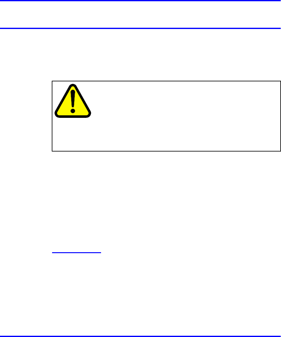
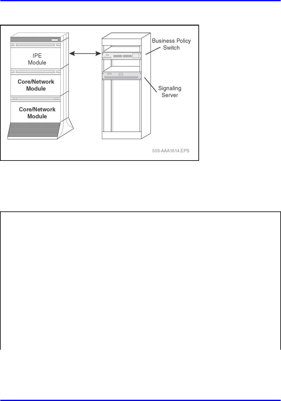
CS 1000M HGand Meridian 1 Option 51C
The CS 1000M HGand the Meridian 1 Option 51C are single-CPU systems
with a half-network group. One Core/Network module and one IPE
module are required. Additional IPE modules, Remote IPE modules, and
application modules can be used.
Table 2 "Specifications for CS 1000M HGand Meridian 1 Option 51C"
(page 17) lists the specifications for these systems. Figure 1 "Meridian 1
Option 51C" (page 16) illustrates an Option 51C system.
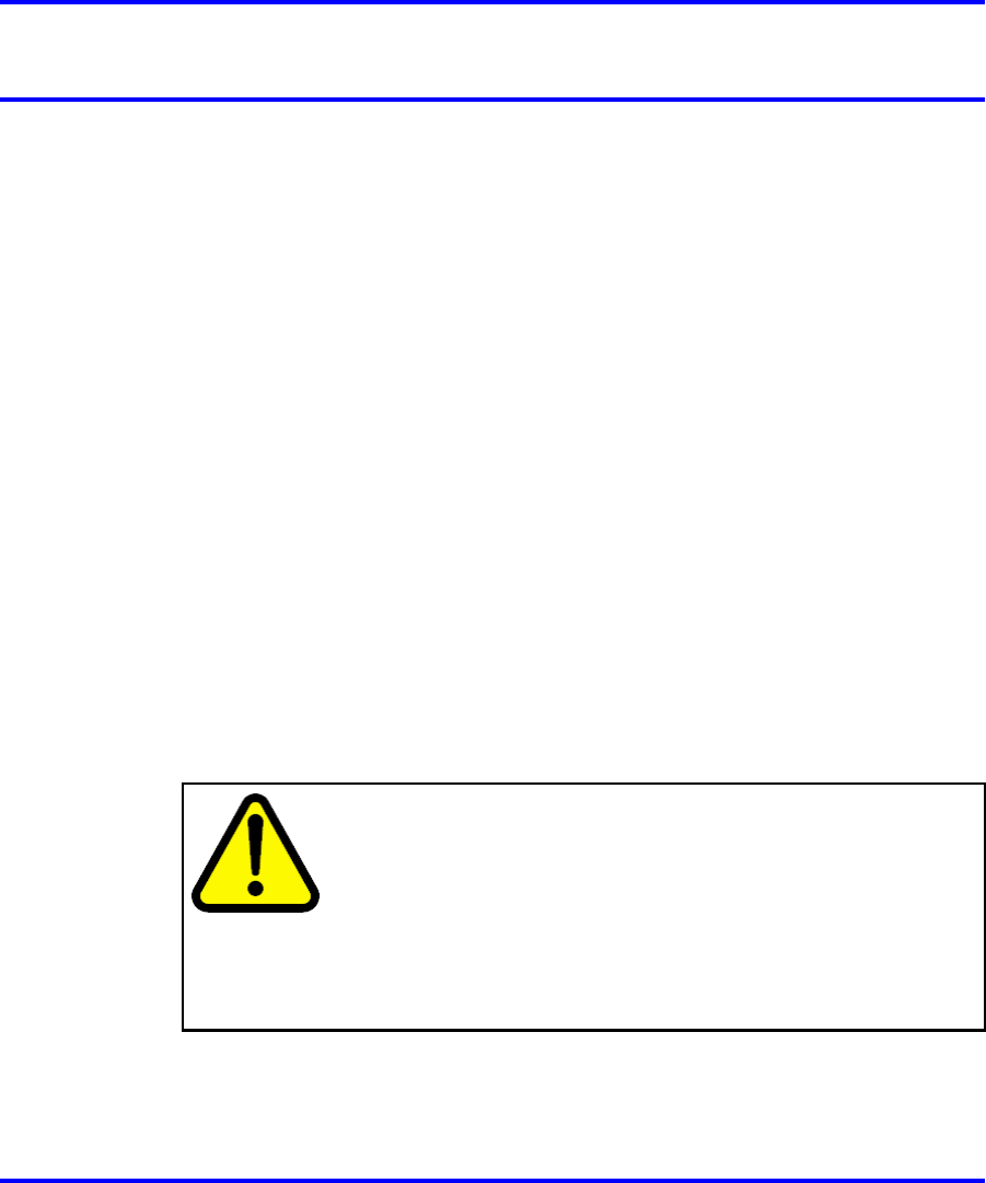
With the addition of a Signaling Server, Meridian 1 Option 51C becomes
a CS 1000M HG. Figure 2 "CS 1000M HG" (page 16) on Figure 2 "CS
1000M HG" (page 16) illustrates a CS 1000M HG.
Nortel Communication Server 1000
Communication Server 1000M and Meridian 1 Large System Overview
NN43021-110 02.05 Standard
30 September 2008
Copyright © 2003-2008 Nortel Networks
.
16 Product description
Figure 1
Meridian 1 Option 51C
Figure 2
CS 1000M HG
Nortel Communication Server 1000
Communication Server 1000M and Meridian 1 Large System Overview
NN43021-110 02.05 Standard
30 September 2008
Copyright © 2003-2008 Nortel Networks
.

System options 17
Table 2
Specifications for CS 1000M HGand Meridian 1 Option 51C
System characteristics:
Maximum number of ports •1000
Input voltage •208 V AC or –48 V DC
Number of CPUs •1
Number of network loops •16
Memory options:
Release 25 •NT5D10 CP or NT5D03 CP card
Succession 3.0 •CP3 NT5D10 CP or CP4 NT5D03 card
CS 1000 Release 4.5 •CP3 NT5D10 CP or CP4 NT5D03 card
Software generic •2811
Base hardware:
Required per system:
•SDI-type card
Required per module:
•CE power supply (CEPS)
•Call Processor (CP) card
•Input/Output Disk Unit with CD-ROM (IODU/C)
•Core to Network Interface (cCNI) card
•3-Port Extender (3PE) card
Core/Network module
•Clock Controller Card (MCLK)
IPE module •IPE power supply
•IPE cards
•System Monitor
•PDU
Pedestal (one per column)
•Blower unit
Nortel Communication Server 1000
Communication Server 1000M and Meridian 1 Large System Overview
NN43021-110 02.05 Standard
30 September 2008
Copyright © 2003-2008 Nortel Networks
.
18 Product description
Table 2
Specifications for CS 1000M HGand Meridian 1 Option 51C (cont’d.)
•Thermostat harness
Top cap (one per column)
•Air probe harness
CS 1000M SGand Meridian 1 PBX 61C CP PIV
The CS 1000M SGand the Meridian 1 PBX 61C CP PIVare dual-CPU
systems with standby processing capability, fully redundant memory,
and a full-network group. Two cPCI Core/Network modules and one IPE
module are required. Additional IPE modules and application modules can
be used.
Figure 3 "Meridian 1 PBX 61C CP PIVor Meridian 1 Option 61C" (page
18) illustrates an Option 61C or Meridian 1 PBX 61C CP PIV.
With the addition of a Signaling Server, Option 61C or Meridian 1 PBX
61C CP PIVbecomes CS 1000M SG. Figure 4 "CS 1000M SG" (page
19) illustrates a CS 1000M SG.
Figure 3
Meridian 1 PBX 61C CP PIVor Meridian 1 Option 61C
Nortel Communication Server 1000
Communication Server 1000M and Meridian 1 Large System Overview
NN43021-110 02.05 Standard
30 September 2008
Copyright © 2003-2008 Nortel Networks
.
System options 19
Figure 4
CS 1000M SG
Table 3 "Specifications for CS 1000M SGand Meridian 1 PBX 61C CP
PIV" (page 19) lists the specifications for CS 1000M SGand Meridian 1
PBX 61C CP PIV.
Table 3
Specifications for CS 1000M SGand Meridian 1 PBX 61C CP PIV
System characteristics:
Maximum number of ports •2000
Input voltage •208 V AC or –48 V DC
Number of CPUs •2 (redundant)
Number of network loops •32
Memory options:
Release 25 •NT5D10 CP or NT5D03 CP card
Succession 3.0 •CP3 NT5D10 or CP4 NT5D03 card
CS 1000 Release 4.5 •CP3 NT5D10 or CP4 NT5D03 card
Software generic •2911
Base hardware:
Nortel Communication Server 1000
Communication Server 1000M and Meridian 1 Large System Overview
NN43021-110 02.05 Standard
30 September 2008
Copyright © 2003-2008 Nortel Networks
.

20 Product description
Table 3
Specifications for CS 1000M SGand Meridian 1 PBX 61C CP PIV (cont’d.)
Required per system:
•SDI-type card
Required per module:
•Call Processor Pentium II®(CP PIV) card
•System Utility (Sys Util) card
•Core to Network Interface (cCNI) card
•3-Port Extender (3PE) card
•Peripheral Signaling card (PS)
•Network cards
•Superloop Network cards
•Conference/TDS card
•CE power supply
•Hybrid Bus Terminators
Cards in the back of the module:
•System Utility Transition (Sys Util Trans) card
Core/Network module (two)
•cCNI Transition (cCNI Trans) card
•IPE power supply
•IPE cards
IPE module
•Controller card
•System Monitor
•PDU
Pedestal (one per column)
•Blower unit
•Thermostat harness
Top cap (one per column)
•Air probe harness
Nortel Communication Server 1000
Communication Server 1000M and Meridian 1 Large System Overview
NN43021-110 02.05 Standard
30 September 2008
Copyright © 2003-2008 Nortel Networks
.
System options 21
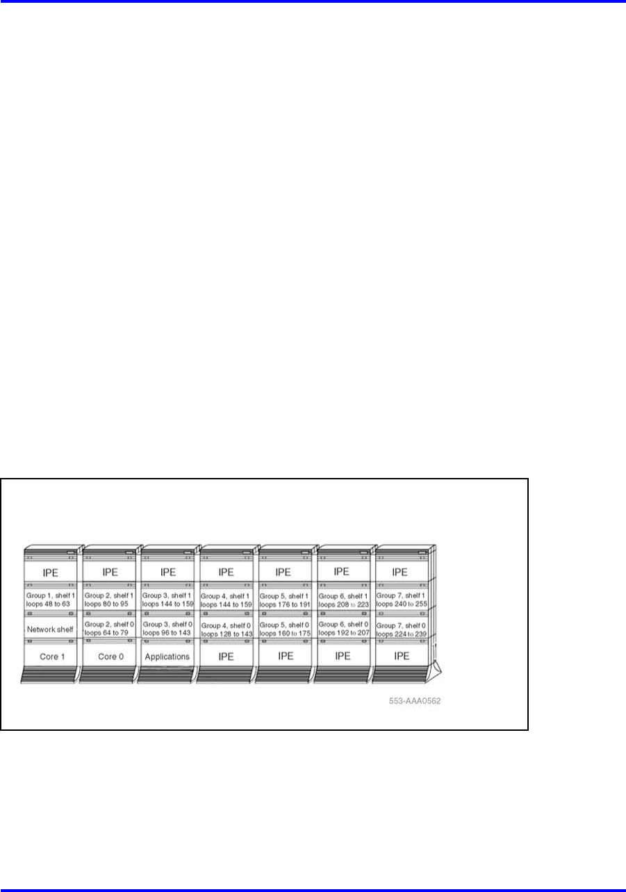
CS 1000M MGand Meridian 1 PBX 81C CP PIV
The CS 1000M MGand Meridian 1 PBX 81Care dual-CPU systems with
standby processing capabilities, fully-redundant memory, and up to eight
full network groups. These systems are equipped with two redundant
input/output processor and disk drive unit combination packs.
The following modules are required:
•two Core/Network modules (provides one network group)
•a minimum of two Network modules (provides one network group)
•a minimum of one IPE module
Additional Network and IPE modules are required for additional network
groups. Application modules can also be used.
Figure 5 "Meridian 1 PBX 81C CP PIVor Option 81C" (page 21) shows a
typical configuration for eight full network groups. Additional columns can
be added, and there can be more than one row of columns.
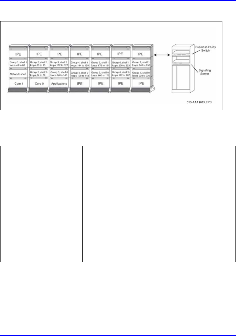
With the addition of a Signaling Server, Meridian 1 Option 81C or Meridian
1 PBX 81C CP PIVbecomes a CS 1000M MG. Figure 6 "CS 1000M MG"
(page 22) illustrates the CS 1000M MG.
Figure 5
Meridian 1 PBX 81C CP PIVor Option 81C
Nortel Communication Server 1000
Communication Server 1000M and Meridian 1 Large System Overview
NN43021-110 02.05 Standard
30 September 2008
Copyright © 2003-2008 Nortel Networks
.
22 Product description
Figure 6
CS 1000M MG
Table 4 "Specifications for CS 1000M MGand Meridian 1 Option 81C CP
PIV" (page 22) lists specifications for the Meridian 1 PBX 81C CP PIV.
Table 4
Specifications for CS 1000M MGand Meridian 1 Option 81C CP PIV
System characteristics:
Maximum number of ports •10 000
Input voltage •208 V AC or –48 V DC
Number of CPUs •2 (redundant)
Number of network loops •256
•128 MB
•256 MB
•CP3 NT5D10, required for CS 1000 Release 4.5
Memory
•CP4 NT5D03, required for CS 1000 Release 4.5
Base hardware:
Nortel Communication Server 1000
Communication Server 1000M and Meridian 1 Large System Overview
NN43021-110 02.05 Standard
30 September 2008
Copyright © 2003-2008 Nortel Networks
.

System options 23
Table 4
Specifications for CS 1000M MGand Meridian 1 Option 81C CP PIV (cont’d.)
Cards in the front of the module:
•Call Processor Pentium IV®(CP PIV) card
•System Utility (Sys Util) card
•Core to Network Interface (cCNI) cards
•3-Port Extender (3PE) card
•Peripheral Signaling card (PS)
•Fiber Junctor Interface (FIJI) card
•Network cards
•Superloop Network cards
•Conference/TDS card
•CE power supply
cCPI Core/Network module (two
side-by-side)
•Hybrid Bus Terminators
Cards in the back of the module:
•System Utility Transition (Sys Util Trans) card
•cCNI Transition (cCNI Trans) cards
•Superloop Network card
•Clock Controller card
•SDI-type card
•DDP2 pack
•MSDL
•IPE power supply
•Controller card
IPE module
•IPE cards
Nortel Communication Server 1000
Communication Server 1000M and Meridian 1 Large System Overview
NN43021-110 02.05 Standard
30 September 2008
Copyright © 2003-2008 Nortel Networks
.

24 Product description
Table 4
Specifications for CS 1000M MGand Meridian 1 Option 81C CP PIV (cont’d.)
•System monitor
•Power Distribution Unit (PDU)
Pedestal (one per column)
•Blower unit
•Thermostat harness
Top cap (one per column)
•Air probe harness
System modules
Each type of module is available in AC-powered and DC-powered versions
(except the NT8D36 InterGroup module that does not require power).
AC-power modules generally require a module power distribution unit
(MPDU) to provide circuit breakers for the power supplies. DC-powered
modules do not require an MPDU because a switch on each power supply
performs the same function as the MPDU circuit breakers.
Note: In the UK, DC-powered modules must be used.
The figures in this chapter show a typical configuration for each module.
DC power is represented in these examples.
NT4N41 Core/Network module
This module provides common control and network interface functions.
With the CS 1000M MGand the Meridian 1 PBX 81C CP PIV, two
Core/Net modules are installed side-by-side. With the CS 1000M SGand
the Meridian 1 PBX 61C CP PIV, the modules are stacked or mounted
side-by-side.
One section of this module houses the common control complex (CPU,
memory, up to four cCNI cards, and mass storage functions). The other
section supports a Conference card, one Peripheral Signaling card, one
3-Port Extender card, and optional network cards.
Note: cCNI card slots 13 and 14 remain empty.
Each Core/Network module houses up to four NT8D04 Superloop Network
Cards for a total of 16 network loops. Superloop Network cards are
cabled to the backplane of an IPE module. In a typical configuration, one
conference/TDS card is configured in the module, leaving 14 voice/data
loops available.
Nortel Communication Server 1000
Communication Server 1000M and Meridian 1 Large System Overview
NN43021-110 02.05 Standard
30 September 2008
Copyright © 2003-2008 Nortel Networks
.
System modules 25
Figure 7 "NT4N41 cPCI Core/Network module" (page 25) illustrates an
NT4N41 Core/Network module.
Core side
The Core side of the module contains the circuit cards that process calls,
manage network resources, store system memory, maintain the user
database, and monitor the system. These circuit cards also provide
administration interfaces through a terminal, modem, or enterprise IP
network.
The Core side runs in redundant mode: one Core operates the system
while the other runs diagnostic checks and remains ready to take over if
the active Core fails. Both Cores are connected to each Network group
depending on hardware configuration. If one Core fails, the second Core
immediately takes over call processing. The Core shelf backplane is a
compact PCI data bus.
Figure 7
NT4N41 cPCI Core/Network module
Network side
The Network side of this module contains the cards for half of the Network
group 0. The other half of Network group 0 resides in the second core
network module.
The CS 1000M MG and Meridian 1 PBX 81C CP PIV support a Fiber
Network Fabric network system with a FIJI card. The double slot FIJI
(NTRB33AF) card is installed in slots 8 and 9 on the Net side of the
Core/Net module, while the single slot FIJI (NTRB33BBE5) card is
installed in slot 9 on the Net side of the Core/Net module.
Nortel Communication Server 1000
Communication Server 1000M and Meridian 1 Large System Overview
NN43021-110 02.05 Standard
30 September 2008
Copyright © 2003-2008 Nortel Networks
.

26 Product description
The double slot FIJI (NTRB33AF) card is installed in slots 2 and 3 on the
Network module, while the single slot FIJI (NTRB33BBE5) card is installed
in slot 2 on the Network module.
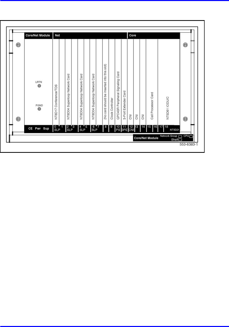
NT5D21 Core/Network module
This module provides common control and network interface functions in
CS 1000M SG, CS 1000M MG, CS 1000M HG, Meridian 1 Option 51C,
Meridian 1 Option 61C, and Meridian 1 Option 81C.
Two Core/Network modules are required in the CS 1000M SG, CS
1000M MG, Meridian 1 Option 81C, and Meridian 1 Option 61C systems
to provide redundant common control operation. If a failure occurs in
one module, the function is transferred to the appropriate circuit cards in
the other module without a loss of service. One Core/Network module is
required in the CS 1000M HGor Option 51C system.
One section of this module houses the common control complex (CPU,
memory, up to three CNI cards, and mass storage functions). The other
section supports a Conference card, one Peripheral Signaling card, one
3-Port Extender card, and optional network cards.
Note: CNI card slots 13 and 14 remain empty.
Each Core/Network module houses up to four NT8D04 Superloop Network
Cards for a total of 16 network loops. Superloop Network cards are
cabled to the backplane of an IPE module. In a typical configuration, one
conference/TDS card is configured in the module, leaving 14 voice/data
loops available.
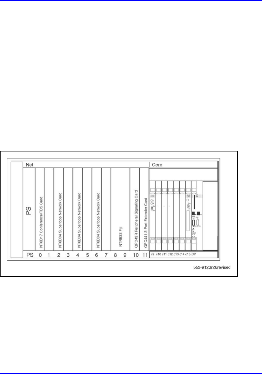
Figure 8 "NT5D21 Core/Network module" (page 27) shows the cards
housed in the NT5D21 Core/Network module as configured for Meridian 1
Option 61C.
Nortel Communication Server 1000
Communication Server 1000M and Meridian 1 Large System Overview
NN43021-110 02.05 Standard
30 September 2008
Copyright © 2003-2008 Nortel Networks
.
System modules 27
Figure 8
NT5D21 Core/Network module
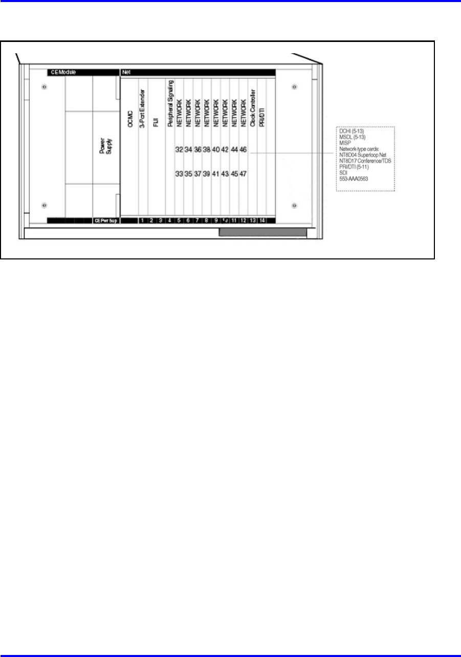
NT8D35 Network module
This module provides the network switching functions in the Meridian 1
Option 81C, Meridian 1 PBX 81C CP PIV, and CS 1000M MG.
Two Network modules are required to make a full network group of 32
loops. A maximum of 16 Network modules (eight network groups) can be
configured in the Meridian 1 Option 81C, CS 1000M MG, and Meridian
1 PBX 81C CP PIV.
The Network module houses up to four NT8D04 Superloop Network
Cards, for a total of 16 network loops. Superloop network cards are
cabled to the backplane of an IPE module. In a typical configuration, one
Conference/TDS card is configured in the module, leaving 14 voice/data
loops available. In CS 1000M MGand Meridian 1 PBX 81C CP PIV, the
Conference/TDS cards are located in the Core/Network module. The Clock
Controller must be installed in slot 13.
Figure 9 "NT8D35 Network module" (page 28) shows the cards housed in
the module.
Nortel Communication Server 1000
Communication Server 1000M and Meridian 1 Large System Overview
NN43021-110 02.05 Standard
30 September 2008
Copyright © 2003-2008 Nortel Networks
.
28 Product description
Figure 9
NT8D35 Network module
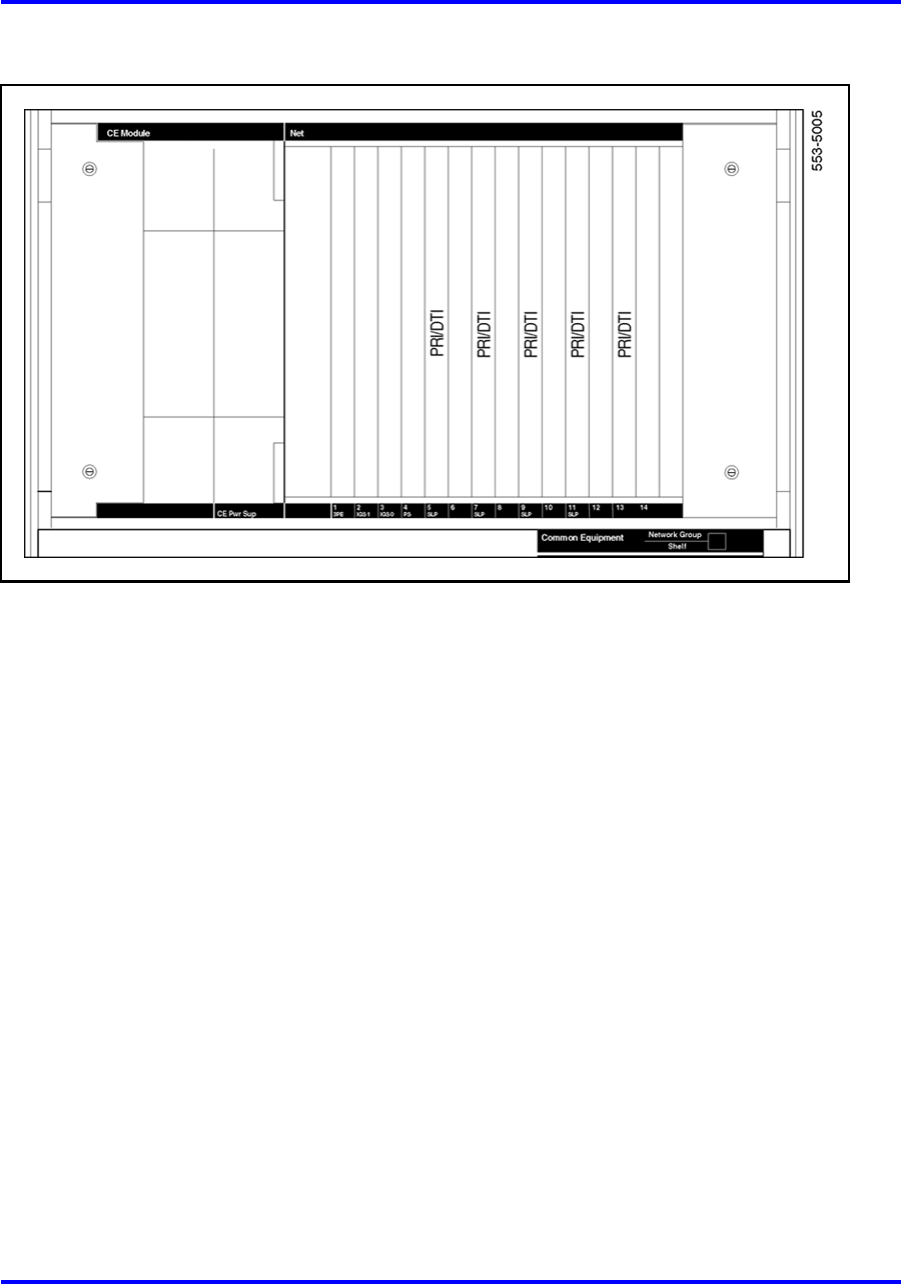
The Network module can be used as a PRI/DTI expansion module. The
number of PRI/DTI expansion modules that can be used is determined by
traffic considerations. Figure 10 "NT8D35 Network module configured for
PRI/DTI expansion" (page 29) shows the card slot configuration when the
Network module is used for PRI/DTI expansion.
Note: The bus terminating units (BTUs) that are equipped in the
NT8D35AA and NT8D35DC Network module configuration are not
required for, and will interfere with, the PRI/DTI expansion configuration.
The NT8D35BA and NT8D35EA Network modules do not use or need
BTUs for any application.
Nortel Communication Server 1000
Communication Server 1000M and Meridian 1 Large System Overview
NN43021-110 02.05 Standard
30 September 2008
Copyright © 2003-2008 Nortel Networks
.
System modules 29
Figure 10
NT8D35 Network module configured for PRI/DTI expansion
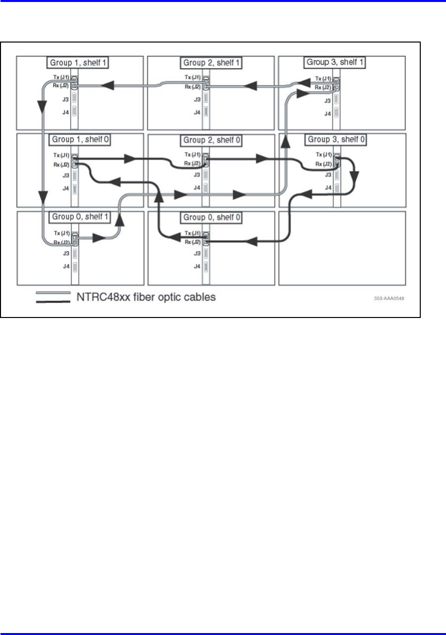
Fiber Network Fabric
Fiber Network Fabric extends and enhances the five-group network
architecture to 8 non-blocking (inter-group) Network groups, with a
resulting expansion in network capacity to 8000 timeslots available for
Intergroup traffic. The Meridian 1 PBX 61C CP PIVcan be upgraded to a
Meridian 1 PBX 81C CP PIVwith Fiber Network Fabric. This upgrade takes
a Meridian 1 PBX 61C CP PIVto a Meridian 1 PBX 81C CP PIVwith two
groups. Figure 11 "Four group Fiber Network Fabric configuration" (page
30) illustrates a four group configuration of Fiber Network Fabric.
Nortel Communication Server 1000
Communication Server 1000M and Meridian 1 Large System Overview
NN43021-110 02.05 Standard
30 September 2008
Copyright © 2003-2008 Nortel Networks
.
30 Product description
Figure 11
Four group Fiber Network Fabric configuration
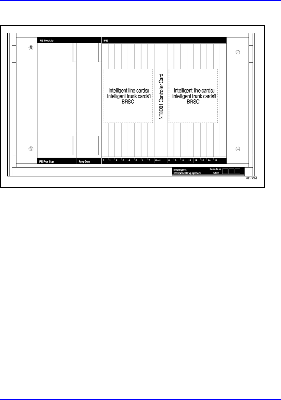
NT8D37 Intelligent Peripheral Equipment module
The Intelligent Peripheral Equipment (IPE) module provides the interface
between network switching and IPE cards, such as intelligent line and
trunk cards, in all Large Systems.
The IPE module houses one NT8D01 Controller Card, which is the
peripheral equipment controller, and up to 16 IPE cards, supporting up
to 512 terminal numbers (256 voice and 256 data). The controller card is
cabled to the NT8D04 Superloop Network Card.
Figure 12 "NT8D37 IPE module" (page 31) shows the card slot
assignments in the module.
Nortel Communication Server 1000
Communication Server 1000M and Meridian 1 Large System Overview
NN43021-110 02.05 Standard
30 September 2008
Copyright © 2003-2008 Nortel Networks
.
System modules 31
Figure 12
NT8D37 IPE module
Fiber Remote IPE module
This module provides fiber-optic links between the network functions in a
Large System and the peripheral controller functions in the Fiber Remote
IPE. A floor-standing column or wall-mounted cabinet is installed at the
remote site and is connected to the Large System using fiber-optic links.
The Fiber Remote IPE provides Large Systems functionality with the
installation of only IPE modules and IPE cards at a distant site. Since the
remote IPE system uses the common equipment and network equipment
of the associated local Large System, it can deliver the same features and
functionality as the local system. See “Fiber Remote IPE” (page 58) for
more information on the Fiber Remote IPE configuration option.
Carrier Remote IPE
The Carrier Remote IPE provides functionality by installing only IPE
modules and IPE cards at a distant site. The Remote IPE shares the
system common and network equipment to provide the same functions
and features to remote subscribers that are available to local system
subscribers.
See “Carrier Remote IPE” (page 61) for more information on the Carrier
Remote IPE configuration option.
Nortel Communication Server 1000
Communication Server 1000M and Meridian 1 Large System Overview
NN43021-110 02.05 Standard
30 September 2008
Copyright © 2003-2008 Nortel Networks
.

32 Product description
Nortel Communication Server 1000
Communication Server 1000M and Meridian 1 Large System Overview
NN43021-110 02.05 Standard
30 September 2008
Copyright © 2003-2008 Nortel Networks
.

33
.
System architecture
Contents This section contains information on the following topics:
“Hardware architecture” (page 34)
“Common control complex” (page 35)
“Network interface” (page 39)
“Intelligent Peripheral Equipment” (page 43)
“Terminal equipment” (page 46)
“Power equipment” (page 47)
“Signaling Server” (page 49)
“Software architecture” (page 55)
“Firmware” (page 56)
“Software” (page 56)
“Office data” (page 56)
“Resident programs” (page 56)
“Nonresident programs” (page 57)
“Configuration options” (page 58)
“Fiber Remote IPE” (page 58)
“Carrier Remote IPE” (page 61)
“Branch Office” (page 62)
“Geographic Redundancy” (page 62)
Nortel Communication Server 1000
Communication Server 1000M and Meridian 1 Large System Overview
NN43021-110 02.05 Standard
30 September 2008
Copyright © 2003-2008 Nortel Networks
.

34 System architecture
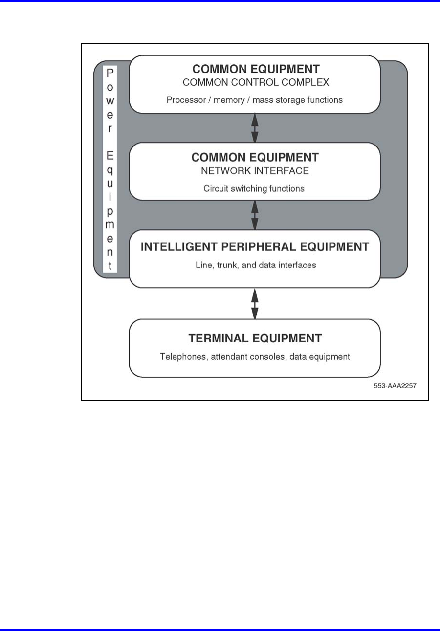
Hardware architecture
CS 1000M and Meridian 1systems are circuit-switched digital systems
that provide voice and data transmission. The internal hardware is divided
into the following functional areas (see Figure 13 "Large System basic
architecture" (page 35) on Figure 13 "Large System basic architecture"
(page 35)):
•Common Control Complex (Common Equipment) circuit cards provide
the processor control, software execution, and memory functions of
the system.
•Network Interface (Common Equipment) circuit cards perform
switching functions between the processor and Intelligent Peripheral
Equipment (IPE) cards.
Note: As shown in Figure 13 "Large System basic architecture" (page
35), the network interface function is generally considered a subset of
the Common Equipment functions.
•IPE circuit cards provide the interface between the network and
connected devices, including Terminal Equipment and trunks.
•Terminal Equipment includes telephones and attendant consoles (and
may include equipment such as data terminals, printers, and modems).
•Power Equipment provides the electrical voltages required for system
operation and cooling, and sensor equipment for system protection.
Nortel Communication Server 1000
Communication Server 1000M and Meridian 1 Large System Overview
NN43021-110 02.05 Standard
30 September 2008
Copyright © 2003-2008 Nortel Networks
.
Hardware architecture 35
Figure 13
Large System basic architecture
Common control complex
The processor is the common control complex of the system. It provides
the sequences to process voice and data connections, monitor call activity,
and perform system administration and maintenance.
The processor communicates with the network interface over a common
control bus that carries the flow of information.
The common control complex consists of:
•the processor card or cards that provide the computing power for
system operation
•system memory that stores all operating software programs and data
unique to each system
Nortel Communication Server 1000
Communication Server 1000M and Meridian 1 Large System Overview
NN43021-110 02.05 Standard
30 September 2008
Copyright © 2003-2008 Nortel Networks
.

36 System architecture
•the disk drive unit that provides mass storage for operating programs
and data
•I/O interfaces that provide an information exchange between the user
and the system
CS 1000M and Meridian 1"core" processor cards support extensive
networking and provide intensive use of software features and
applications, including call centers of up to 1000 agents.
The core software architecture incorporates a real-time multitasking
operating system, as well as code that delivers features and call
processing. This architecture guarantees feature transparency to the user
upgrading the core CPU. The core architecture also provides significant
operation, administration, and maintenance enhancements for the people
who work closely with the system software and hardware.
All core overlays reside in Dynamic Random Access Memory (DRAM) after
they are loaded from the hard disk during an initial software load (software
is shipped on redundant hard disks). The Resident Overlays featured in
core-based systems ensure subsecond speeds in accessing the overlays.
The capacity enhancement in the core architecture is provided by the core
control complex. In Large Systems with cPCI Core/Network modules,
the core control complex refers to the two Core/Network modules
(Core/Network 0 and Core/Network 1). The Core and Core/Network
modules are fully redundant, with Core 1 duplicating the contents of Core
0.
The backplane in the CS 1000M MGand Meridian 1 PBX 81C CP PIVCore
modules is a compact Peripheral Component Interconnect (PCI) data bus.
PCI provides a high-speed data path between the CPU and peripheral
devices. PCI runs at 33MHz, supports 32- and 64-bit data paths and bus
mastering.
The backplane in the system is divided into "core" and "network" sides.
The "network" side allows up to eight network cards to be installed for call
processing capability.
In the CS 1000M HGand Option 51C Core/Network module, the core side
houses the following equipment:
•one Call Processor (CP) card
•one Input/Output Disk Unit with CD-ROM (IODU/C)
•one Core-to-Network Interface (CNI or CNI-3) card
Nortel Communication Server 1000
Communication Server 1000M and Meridian 1 Large System Overview
NN43021-110 02.05 Standard
30 September 2008
Copyright © 2003-2008 Nortel Networks
.

Hardware architecture 37
In the CS 1000M SGand Meridian 1 PBX 61C CP PIVCore/Network
module, the core side houses the following equipment:
•one Call Processor Pentium IV®(CP PIV) card
•one System Utility (Sys Util) card
•one Core-to-Network Interface (cCNI) cards
•one System Utility Transition (Sys Util Trans) card
•four cCNI Transition (cCNI Trans) cards
Cabling between the CP cards allows memory shadowing and dual-CPU
operation.
The CNI and CNI-3 cards provide the interface between the IPB and the
network shelf, and between the CP card and three-port extender cards in
the network shelf. Each CNI card provides two ports. Each CNI-3 card
supports three ports. In a typical configuration, three CNI-3 cards support
eight network groups.
Software is now installed with 2 Compact Flash cards: one embedded on
the CP PIV pack (FMD) 1GB, and one hot swappable (RMD) with 512 MB.
The system uses a Security Device and an electronic Keycode to perform
security authentication. The security device is located on the utility card.
The Keycode file contains information about which features the system
provides as well as License limits.
Core/Net modules diagnose faults in field-replaceable units for all core
hardware, including cables. In case of a failure, a message appears on the
system terminal and on the Liquid Crystal Display (LCD) of the CP card.
All messages can be stored in a file for future diagnostics.
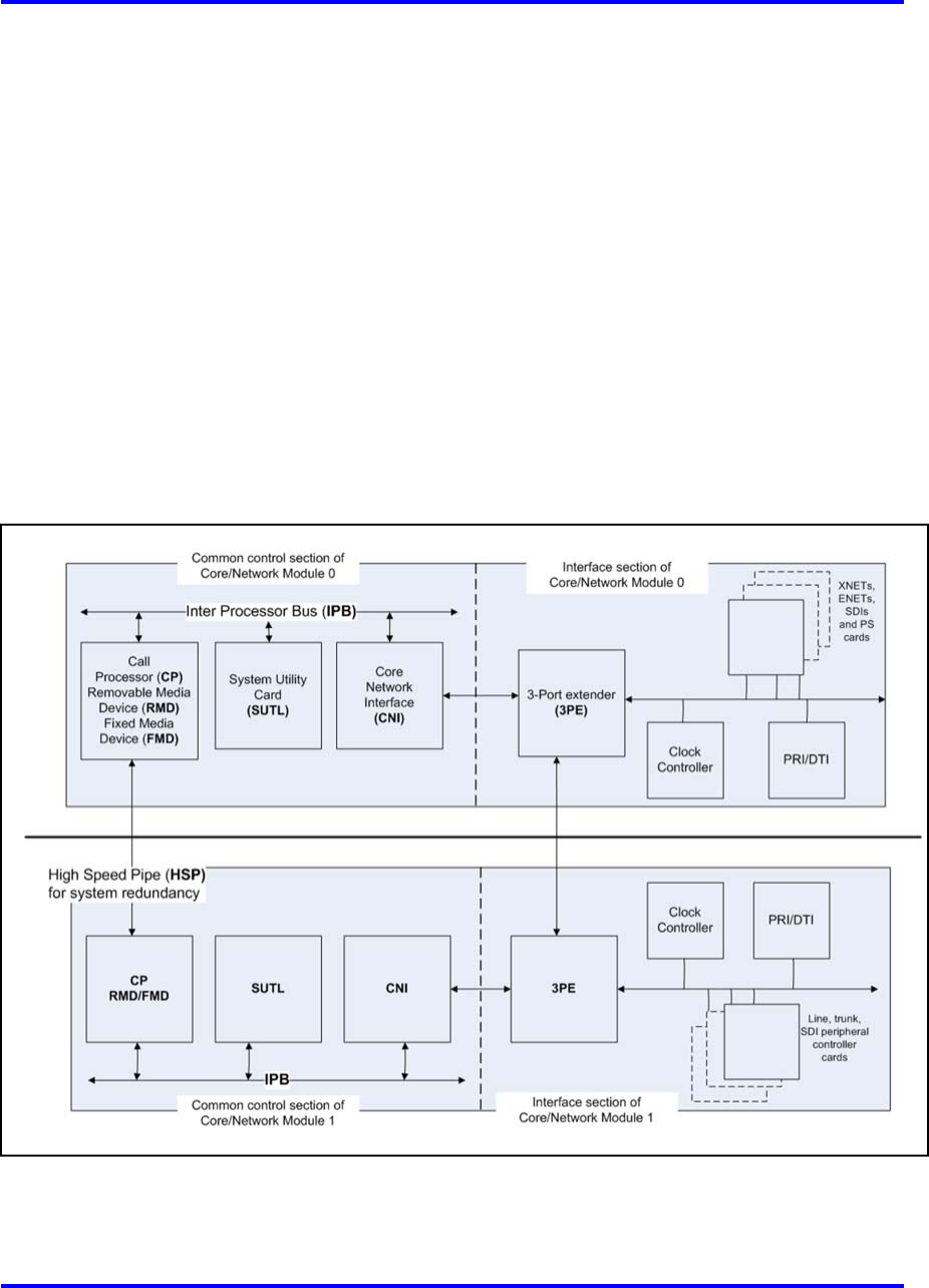
Figure 14 "CS 1000M SGand Meridian 1 PBX 61C CP PIVcore complex"
(page 38) provides a block diagram of the CS 1000M SGand Meridian 1
PBX 61C CP PIVcore architecture.
In the CS 1000M MGand Meridian 1 PBX 81CcPCI Core/Network module,
the core side houses the following equipment:
•one Call Processor Pentium IV®(CP PIV) card
•one System Utility (Sys Util) card
•up to four Core to Network Interface (cCNI) cards
•one System Utility Transition (Sys Util Trans) card
•four cCNI Transition (cCNI Trans) cards
Nortel Communication Server 1000
Communication Server 1000M and Meridian 1 Large System Overview
NN43021-110 02.05 Standard
30 September 2008
Copyright © 2003-2008 Nortel Networks
.
38 System architecture
Core/Net modules diagnose faults in field-replaceable units for all core
hardware, including cables. In case of a failure, a message appears on the
system terminal and on the LCD of the faceplate of the utility card.
Core to Core Ethernet connection (LAN1 to LAN2) between the CP PIV
cards allows memory shadowing and dual-CPU operation.
The cCNI Transition cards connect the Core module cards to the 3PE
cards in the Network modules. Each Core module contains between
one and four cCNI cards. Since each cCNI card can connect up to two
Network groups, each Core is connected to a minimum of two groups
and a maximum of eight groups. The number of cCNI cards in a system
depends on the number of Network groups in that system. The first cCNI
card that connects to Network group 0 and group 1 is installed in slot c9 of
each Core/Net module. Each additional cCNI card is installed in ascending
order from slots c10 to c12.
Figure 14
CS 1000M SGand Meridian 1 PBX 61C CP PIVcore complex
Nortel Communication Server 1000
Communication Server 1000M and Meridian 1 Large System Overview
NN43021-110 02.05 Standard
30 September 2008
Copyright © 2003-2008 Nortel Networks
.

Hardware architecture 39
The System Utility card supports Card ID. The card provides an interface
between the security device and the computer, and an interface between
the XSM and display panel for each Core/Net card cage. This card also
includes a switch on the faceplate to enable or disable the Core cards.
The System Utility Transition card provides connections for the security
device, the system monitor, and the status panel. This Transition card
is mounted on the rear of the backplane (back side) directly behind the
System Utility card.
The cCNI Transition cards provide the cable connections to the 3PE
Termination Panel at the back of the module. A cCNI Transition card
is mounted directly behind each cCNI card (on the back of the Core
backplane). Four cCNI Transition cards for Core/Net module are installed
in the factory regardless of how many cCNI main cards are configured for
the system.
Network interface
Network switching, based on digital multiplexed loops, interconnects
peripheral ports. A loop transmits voice, data, and signaling information
over a bidirectional path between the network and peripheral ports.
Network cards digitally transmit voice and data signals, using space
switching and Time Division Multiplexing (TDM) technology. Network
switching also requires service loops (such as conference and TDS loops),
which provide call progress tones and outpulsing.
The following cards provide basic network switching control:
•The NT8D04 Superloop Network card provides switching for four loops
grouped together in an entity called a superloop.
•The NT5D12 Digital Trunk card provides switching for two DTI/PRI
loops and takes one network slot.
•The NT5D97 Digital Trunk card provides switching for two DTI2/PRI2
loops and takes one network slot.
The NT5D12 and NT5D97 Digital Trunk cards replace the functionality of
the QPC720 DTI/PRI and QPC414 Network card, which provided switching
for two loops.
Nortel Communication Server 1000
Communication Server 1000M and Meridian 1 Large System Overview
NN43021-110 02.05 Standard
30 September 2008
Copyright © 2003-2008 Nortel Networks
.

40 System architecture
Network organization
Network loops are organized into groups. A system is generally configured
as one of the following:
•a half group system (CS 1000M HG) that provides up to 16 loops
•a single group system (CS 1000M SG) that provides up to 32 loops
•a multi-group system (CS 1000M MG) that provides up to 256 loops
The Fiber Junctor Interface (FIJI) cards in the Network modules are
connected with fiber-optic cables to form a Dual Ring Fiber Network. This
network consists of two separate rings: one ring connects all the Network
shelf 0s while the second ring connects all the Network shelf 1s. This
network communicates on a subset of the Sonet OC12c protocol (622 MB
bandwidth on each ring).
The Dual Ring fiber-optic cable configuration provides complete
non-blocking communication between the Network groups; this eliminates
the incidence of busy signals for calls switched between groups. Each FIJI
card can handle 32 PCM links. A system of eight Network groups provides
8000 timeslots for 4000 simultaneous conversations.
This Dual Ring network is fully redundant: each of the fiber-optic cable
rings is capable of handling the traffic for an entire eight group network. If
a fault in one ring is detected, the other ring automatically takes over call
processing. No calls are lost during the switchover.
The Dual Ring Fiber network operated under four states:
•Normal
—Traffic is shared between the two rings.
—Each FIJI card drives 480 timeslots.
•Full
—Traffic is handled by a single ring.
—Each FIJI card drives 960 timeslots
•Survival
—FIJI cards in both rings are used to maintain intergroup traffic.
•Disabled
—The ring is inactive and does not support call processing.
Nortel Communication Server 1000
Communication Server 1000M and Meridian 1 Large System Overview
NN43021-110 02.05 Standard
30 September 2008
Copyright © 2003-2008 Nortel Networks
.
Hardware architecture 41
Superloop network configurations
By combining four network loops, the superloop network card makes 120
timeslots available to IPE cards. Compared to regular network loops, the
increased bandwidth and a larger pool of timeslots increases network
traffic capacity for each 120-timeslot bundle by 25 percent (at a P0.1 grade
of service).
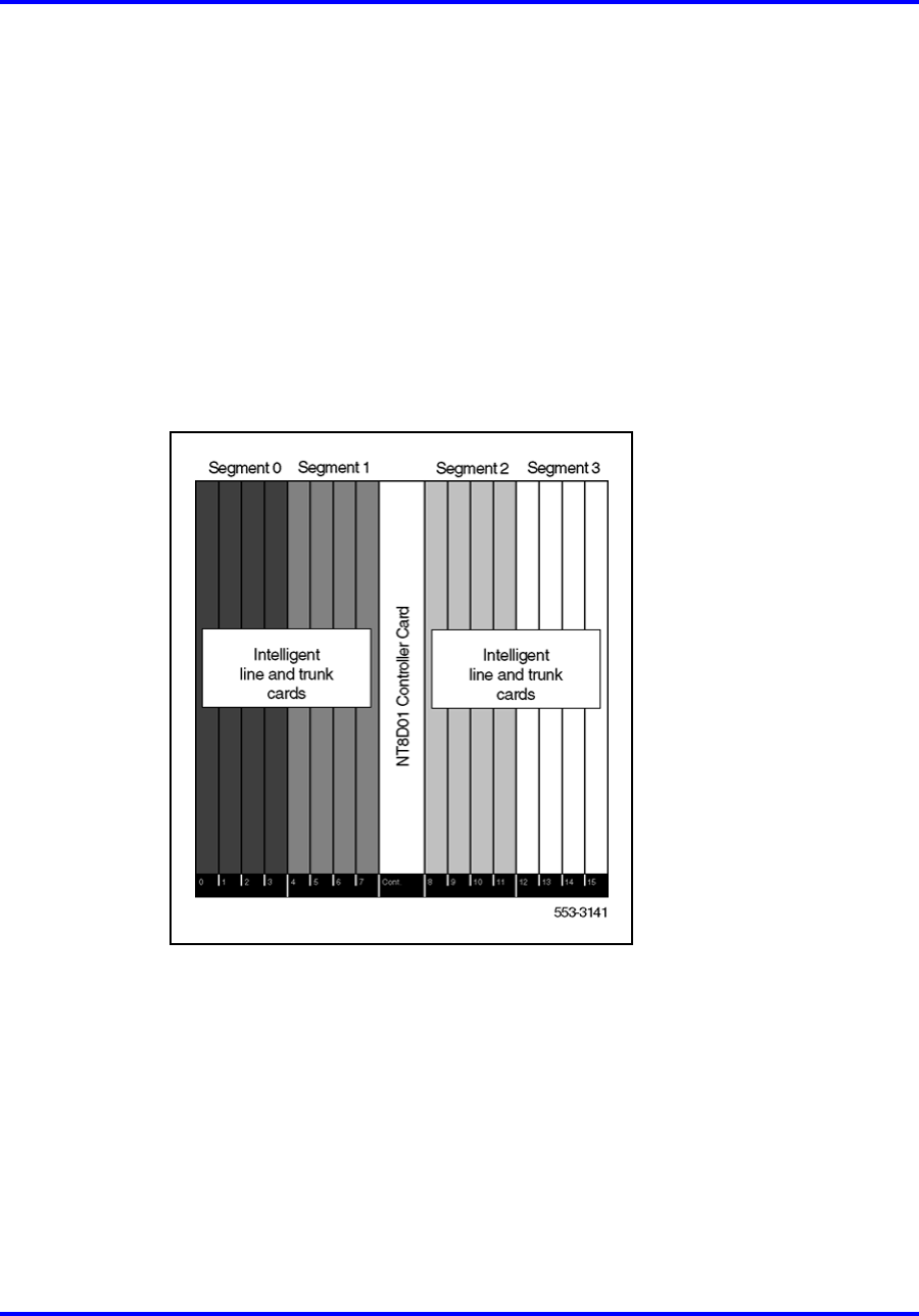
The NT8D37 IPE module is divided into segments numbered 0–3 of four
card slots each (see Figure 15 "Superloop segments in the IPE module"
(page 41)). Segment 0 consists of slots 0–3, segment 1 consists of slots
4–7, segment 2 consists of slots 8–11, and segment 3 consists of slots
12–15.
Figure 15
Superloop segments in the IPE module
A superloop is made up of NT8D04 Superloop Network cards, NT8D01AC
or NT8D01BC Controller-4 or NT8D01AD Controller-2 cards, and from
one to eight IPE segments. The NT8D01BC Controller-4 replaces the
NT8D01AC and NT8D01AD Controller cards for replacements and new
installations.
A number of superloop-to-segment configurations are possible:
•one segment per superloop requires four superloop network cards and
one controller-4 card
•two segments per superloop requires two superloop network cards and
one controller-2 card
Nortel Communication Server 1000
Communication Server 1000M and Meridian 1 Large System Overview
NN43021-110 02.05 Standard
30 September 2008
Copyright © 2003-2008 Nortel Networks
.

42 System architecture
•four segments per superloop requires one superloop network card and
one controller-2 card
•eight segments per superloop requires one superloop network card
and two controller-2 cards
•one segment per superloop/three segments on a second superloop
requires two superloop network cards and one controller-2 card
•two segments per superloop/six segments on a second superloop
requires two superloop network cards and two controller-2 cards
As an example of a superloop configuration, Figure 16 "Eight segments
per superloop" (page 43) shows eight segments per superloop. If a
segment in this configuration is equipped with analog line cards and trunk
cards, a high concentration environment of 120 timeslots to 128–512
Terminal Numbers (TNs) is provided. If half of the data TNs on digital
line cards are enabled, this configuration provides a concentration of 120
timeslots to 768 TNs.
For a detailed description of superloop-to-segment configurations, see
Communication Server 1000M and Meridian 1 Large System Planning and
Engineering (NN43021-220),.
Nortel Communication Server 1000
Communication Server 1000M and Meridian 1 Large System Overview
NN43021-110 02.05 Standard
30 September 2008
Copyright © 2003-2008 Nortel Networks
.
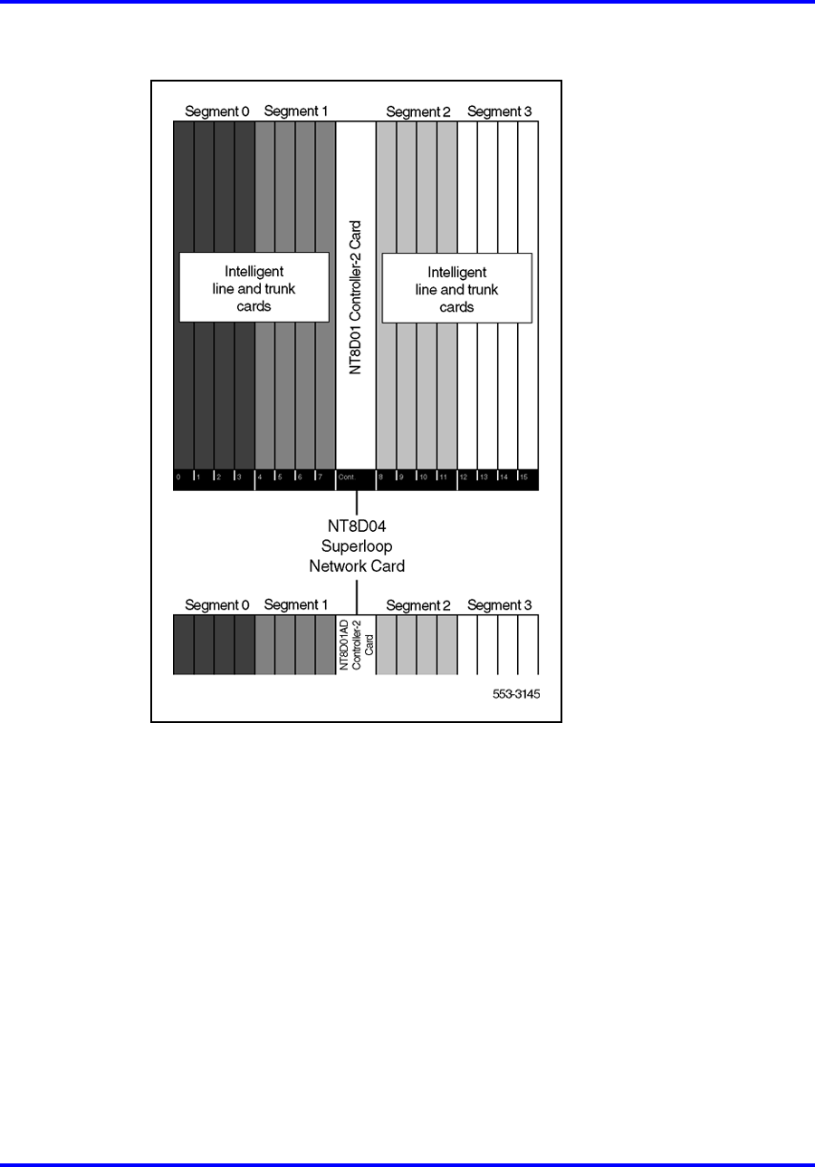
Hardware architecture 43
Figure 16
Eight segments per superloop
Intelligent Peripheral Equipment
Using pulse code modulation (PCM), Intelligent Peripheral Equipment
(IPE) converts analog signals to digital signals before switching is
performed by the network. This conversion method samples the
amplitude of the analog signal at a rate of twice the highest signal
frequency, then converts the amplitude into a series of coded pulses. For
telecommunications, the PCM-sampling frequency standard is 8 kHz.
Compressing-expanding (companding) PCM is a standard technique
for using 8-bit words to efficiently represent the range of voice and data
signals. Two standards for companding, A-Law and µ-Law, are recognized
worldwide. IPE conforms to both standards; the standard required is
selected through software.
Nortel Communication Server 1000
Communication Server 1000M and Meridian 1 Large System Overview
NN43021-110 02.05 Standard
30 September 2008
Copyright © 2003-2008 Nortel Networks
.

44 System architecture
IPE is associated with network loops. IPE cards are supported by NT8D04
Superloop Network Card loops. The traffic requirements of all IPE cards
provisioned on a particular network loop must match the traffic capacity
of that loop.
IPE includes:
•controller cards that provide timing and control sequences and
monitoring capabilities
•analog and digital line and trunk cards that provide interfaces to
equipment outside the modules (such as telephones, data terminals,
and trunks)
Table 5 "Intelligent Peripheral Equipment cards" (page 44) lists the IPE
cards and the number of terminations each supports.
Table 5
Intelligent Peripheral Equipment cards
Intelligent Peripheral Equipment cards Number of
terminations
Controller cards:
NT8D01 Controller Card-4 N/A
NT8D01 Controller Card-2 N/A
Line cards:
NT1R20 OPS Analog Line card 8
NT5K02 Analog Line card 16
NT5K96 Analog Line card 16
NT8D02 Digital Line card 16 to 32
NT8D09 Analog Message Waiting Line card 16
Trunk cards:
NT5K07 Universal Trunk card 8
NT5K17 Direct Dial Inward Trunk card 8
NT5K18 Extended CO Trunk card 8
NT5K19 E&M/2280 Hz Trunk card 4
NT5K36 Direct Inward/Direct Outward Dial card 4
NT5K70 Extended CO Trunk card 8
Note: Terminal number (TN) density per segment is 16 to 128 TNs, with 64
to 512 TNs per IPE module. The maximum TN density assumes all slots
are equipped with NT8D02 Digital Line cards with 16 voice and 16 data TNs
provisioned. A typical mix of line and trunk cards yields a nominal density of 64
TNs per segment, 256 TNs per IPE module.
Nortel Communication Server 1000
Communication Server 1000M and Meridian 1 Large System Overview
NN43021-110 02.05 Standard
30 September 2008
Copyright © 2003-2008 Nortel Networks
.

Hardware architecture 45
Table 5
Intelligent Peripheral Equipment cards (cont’d.)
Intelligent Peripheral Equipment cards Number of
terminations
NT5K71 Extended CO Trunk card 4
NT5K72 E&M Trunk card 4
NT5K82 Extended CO Trunk card 8
NT5K83 E&M Trunk card 4
NT5K84 Direct Inward Dial Trunk card 8
NT5K90 Extended CO Trunk card 8
NT5K93 Extended CO Trunk card 8
NT5K99 Extended CO Trunk card 8
NT8D14 Universal Trunk card 8
NT8D15 E&M Trunk card 4
NTAG03 Extended CO Trunk card 8
NTAG04 Extended CO/Direct Inward Dial card 8
NTAG36 Meridian Integrated Recorded Announcement
card 8
NTCK16 Generic Extended Flexible CO card 8
Special:
NT5K20 Extended Tone Detector card 8
NT5K48 Global Extended Tone Detector card 8
NT5K92 Direct Inward Dial Tester card 1
Note: Terminal number (TN) density per segment is 16 to 128 TNs, with 64
to 512 TNs per IPE module. The maximum TN density assumes all slots
are equipped with NT8D02 Digital Line cards with 16 voice and 16 data TNs
provisioned. A typical mix of line and trunk cards yields a nominal density of 64
TNs per segment, 256 TNs per IPE module.
Intelligent Peripheral Equipment remote location
In a local operating environment, IPE can be housed up to 15.2 m (50 ft)
from the Common Equipment. IPE installed in a remote location extends
this range, allowing approximately 112.6 km (70 miles) between local and
remote facilities.
This extension is achieved by converting multiplexed loop signals to a form
compatible with the commonly used T-1 type digital transmission system.
Refer to Table 5 "Intelligent Peripheral Equipment cards" (page 44) for a
list of IPE cards for use at the remote site.
Nortel Communication Server 1000
Communication Server 1000M and Meridian 1 Large System Overview
NN43021-110 02.05 Standard
30 September 2008
Copyright © 2003-2008 Nortel Networks
.

46 System architecture
Any medium that conforms to the DS-1 format (1.544 Mbps) can be
used to link local and remote sites, including digital microwave radio and
fiber-optic transmission systems.
Terminal equipment
Large Systems support a wide range of telephones, including multiple-line
and single-line telephones, as well as digital telephones with key and
display functions and data transmission capabilities. A range of options
for attendant call processing and message center applications is also
available. In addition, a number of add-on devices are available to extend
and enhance the features of telephones and consoles. Add-on devices
include key/lamp modules, lamp field arrays, handsets, and handsfree
units.
For more information refer to Telephones and Consoles Fundamentals
(NN43001-567), and IP Phones Fundamentals (NN43001-368,).
Digital telephones
Analog-to-digital conversion takes place in the digital telephone itself,
rather than in the associated Peripheral Line card. This eliminates
attenuation, distortion, and noise generated over telephone lines. Signaling
and control functions are also handled digitally. Time Compression
Multiplexing (TCM) is used to integrate the voice, data, and signaling
information over a single pair of telephone wires.
For applications where data communication is required, Meridian 1 digital
telephones offer an integrated data option that provides simultaneous
voice and data communication over single pair wiring to a port on a digital
line card.
CS 1000Mand Meridian 1Large Systems supports telephones as described
in:
•IP Phones Fundamentals (NN43001-368),
•Telephones and Consoles Fundamentals (NN43001-567),
•WLAN Handsets Fundamentals (NN43001-505),
•DECT Fundamentals (NN43120-114),
Attendant consoles
Meridian 1 attendant consoles provide high-volume call processing.
Indicators and a 4 x 40 liquid crystal display (LCD) provide information
required for processing calls and personalizing call answering. Loop keys
and Incoming Call Indicator (ICI) keys allow the attendant to handle calls in
sequence or to prioritize answering for specific trunk groups. An optional
busy lamp field provides the attendant with user status.
Nortel Communication Server 1000
Communication Server 1000M and Meridian 1 Large System Overview
NN43021-110 02.05 Standard
30 September 2008
Copyright © 2003-2008 Nortel Networks
.

Hardware architecture 47
Meridian attendant consoles support attendant message center options.
The attendant console can be connected to a PC to provide electronic
directory, dial-by-name, and text messaging functions. All call processing
features can be accessed using the computer keyboard.
Power equipment
Large Systems provide a modular power distribution architecture.
Each column includes:
•a system monitor that provides:
—power, cooling, and general system monitoring capabilities
—error and status reporting down to the specific column and module
•circuit breaker protection
•a cooling system with forced air impellers that automatically adjusts
velocity to meet the cooling requirements of the system
•backup capabilities
Each module includes:
•an individual power supply unit with shut-off (switch or breaker)
protection
•a universal quick-connect power wiring harness that distributes input
voltages and monitor signals to the power supply
All options are available in both AC-power and DC-power versions.
The selection of an AC- or DC-powered system is determined primarily
by reserve power requirements and existing power equipment at the
installation site.
Although AC-powered and DC-powered systems have different internal
power components, the internal architecture is virtually identical. AC- and
DC-powered systems differ primarily in the external power components.
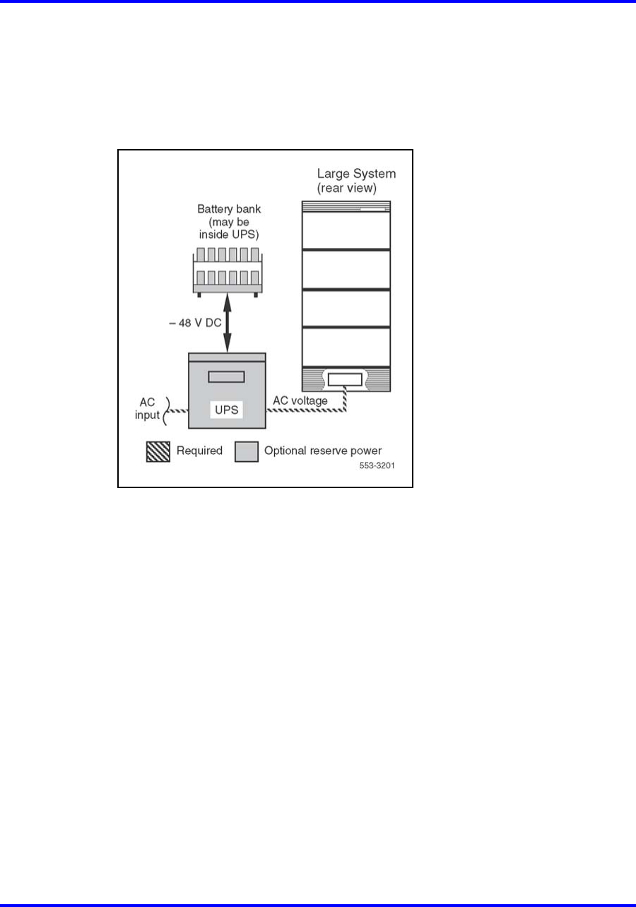
AC power
AC-powered systems require no external power components and can
plug directly into commercial AC (utility) power. AC-powered systems are
especially suitable for applications that do not require reserve power. They
are also recommended systems that require reserve power with backup
times ranging from 15 minutes to 8 hours.
If reserve power is required with an AC-powered system, an
Uninterruptible Power Supply (UPS), along with its associated batteries
(either internal or external to the unit), is installed in series with the AC
power source (see Figure 17 "ExternalAC-power architecture with reserve
Nortel Communication Server 1000
Communication Server 1000M and Meridian 1 Large System Overview
NN43021-110 02.05 Standard
30 September 2008
Copyright © 2003-2008 Nortel Networks
.
48 System architecture
power" (page 48)). An AC-powered system that does not require long-term
backup can benefit from a UPS with short-term backup because the UPS
typically provides power conditioning during normal operation, as well as
reserve power during short outages or blowouts.
Figure 17
ExternalAC-power architecture with reserve power
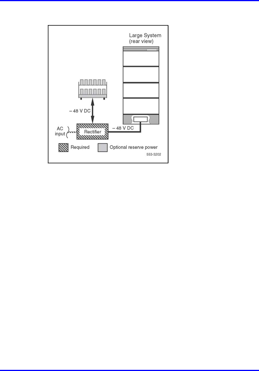
DC power
DC-powered systems always require external rectifiers to convert
commercial AC power into the standard –48 V DC required within the
system (see Figure 18 "ExternalDC-power architecture with reserve power"
(page 49)). Batteries are generally used with DC-powered systems, as
the traditional telecommunications powering method is for the rectifiers to
continuously charge a bank of batteries, while the system power "floats"
in parallel on the battery voltage. However, batteries are only required
if reserve power is needed.
A variety of rectifiers and distribution equipment can be used to supply
external DC power. Existing customer equipment can be used or a system
that Nortel either supplies or recommends, such as the Small or Large
Candeo, can be used. The Small Candeo is appropriate for Single Group
or Multi Group systems that do not require more than 300 A, while the
Large Candeo is suitable for larger systems. In all cases, equipment
for rectification and distribution is required, while reserve batteries are
optional.
Nortel Communication Server 1000
Communication Server 1000M and Meridian 1 Large System Overview
NN43021-110 02.05 Standard
30 September 2008
Copyright © 2003-2008 Nortel Networks
.
Hardware architecture 49
Figure 18
ExternalDC-power architecture with reserve power
Candeo DC power system
The Candeo platform provides a simple, quick-to-deploy, and
easy-to-operate power solution. Based upon modular building blocks
(rectifiers, System Manager, DC distribution, and battery connection
modules), the system is designed to power -48 V DC applications. The
Large Candeo power system uses 50 A rectifiers and has a capacity of
1000 A; the Small Candeo (SP48300) uses 30 A rectifiers and has a
capacity of 300 A. Both Large and Small Candeo systems provide "plug
and walk-away" installation and setup. The platform can be reconfigured or
expanded while it remains online.
Signaling Server
CS 1000Msystems use a Signaling Server. The Signaling Server is an
PC-based server that provides a central processor to drive H.323 and
Session Initiation Protocol (SIP) signaling for IP Phones and IP Peer
Networking. It provides signaling interfaces to the IP network using
software components that operate on the VxWorksª real-time operating
system.
The legacy Nortel ISP1100 Signalling Server can still be used.
Nortel Communication Server 1000
Communication Server 1000M and Meridian 1 Large System Overview
NN43021-110 02.05 Standard
30 September 2008
Copyright © 2003-2008 Nortel Networks
.

50 System architecture
CS 1000 Release 5.5 introduces three new servers that can host a CS
1000 Release 5.5 Signaling Server:
•“Nortel Common Processor Pentium Mobile server” (page 50)
•“International Business Machines X306m server” (page 51)
•“Hewlett Packard DL320-G4 server” (page 51)
The Signaling Server has both an ELAN and TLAN network interface. The
Signaling Server communicates with the Call Server through an ELAN
subnet.
The Signaling Server is mounted in a 19-inch rack. The Signaling Server
can be installed in a load-sharing redundant configuration for higher
scalability and reliability.
The following software components operate on the Signaling Server:
•“Terminal Proxy Server” (page 52) (TPS)
•“SIP/H.323 Signaling Gateways” (page 52)
•“Network Routing Service” (page 53) (NRS)
•“Element Manager” (page 55)
•Application Server
Signaling Server software elements can coexist on one Signaling Server or
reside individually on separate Signaling Servers, depending on traffic and
redundancy requirements for each element. For any co-resident Signaling
Server software element combination the maximum call rate supported
is 10K cph.
For more information about H.323 and SIP Trunking, refer to IP Peer
Networking Installation and Commissioning (NN43001-313),.
Nortel Common Processor Pentium Mobile server
The Nortel Common Processor Pentium Mobile (CP PM) server is a
high-performance, circuit card-based server that can be configured as
a Call Server or a Signaling Server in a CS 1000 Release 5.5 system.
The CP PM NTDW66 model can be configured as a Signaling Server and
installed in a Universal Equipment Module (UEM) in a CS 1000M SG or
CS 1000M MG system.
The Nortel CP PM Signaling Server delivers capacity improvement by
providing flexible scaling from 0 to 22,000 IP Phones and a 70% increase
in power for Signaling Server applications. The increased application
power and capacity, coupled with the reduction in foot print and power
consumption, means a lower cost of ownership.
Nortel Communication Server 1000
Communication Server 1000M and Meridian 1 Large System Overview
NN43021-110 02.05 Standard
30 September 2008
Copyright © 2003-2008 Nortel Networks
.

Hardware architecture 51
The Nortel CP PM server has the following components:
•Intel Pentium M processor (1.4 Ghz)
•internal hard drive
•hot-pluggable Compact Flash (CF) card slot in the faceplate
•2 GB of SDRAM
•One 1 GB/s Ethernet port
•Two 100BaseT Ethernet ports
•Two serial ports
•One USB port
For more information about installing and configuring the Nortel CP
PM server as a Signaling Server, seeSignaling Server Installation and
Commissioning (NN43001-312),.
International Business Machines X306m server
The International Business Machines (IBM) X306m 1U server is a
rack-mounted, Pentium 4, PC-based, industry-standard, commercial
off-the-shelf (COTS) server.
The IBM X306m 1U server has the following components:
•Intel Pentium 4 processor (3.6 GHz)
•Two 80 GB simple swap Serial ATA hard drives (1 drive configured)
•8 GB of RAM PC4200 DDR II by means of 4 DIMM slots (2 GB
configured)
•Two 1 GB/s Ethernet ports
•One DVD-COMBO (DVD/CD-RW) drive
•One serial port
•Four USB ports
For more information about installing and configuring the IBM X306m
server as a Signaling Server, see Signaling Server Installation and
Commissioning (NN43001-312).
Hewlett Packard DL320-G4 server
The Hewlett Packard (HP) DL320-G4 1U server is a rack-mounted,
Pentium 4, PC-based, industry-standard, commercial off-the-shelf (COTS)
server.
Nortel Communication Server 1000
Communication Server 1000M and Meridian 1 Large System Overview
NN43021-110 02.05 Standard
30 September 2008
Copyright © 2003-2008 Nortel Networks
.

52 System architecture
The HP DL320-G4 1U server has the following components:
•Intel Pentium 4 processor (3.6 GHz)
•Two 80 GB SATA Hard drives (1 configured)
•4 GB PC2-4200 ECC DDR2 SDRAM (2 GB configured
•Two 10/100/1000BaseT Ethernet ports
•One CD-R/DVD ROM drive
•One serial port
•Three USB ports
•For more information about installing and configuring the HP DL320-G4
server as a Signaling Server, see Signaling Server Installation and
Commissioning (NN43001-312),.
Terminal Proxy Server
The Terminal Proxy Server (TPS) acts as a signaling gateway between
the IP Phones and the Call Server using the UNIStim protocol. It performs
the following functions:
•converts the IP Phone UNIStim messages into messages the Call
Server can interpret
•allows IP Phones to access telephony features provided by the Call
Server
The TPS also controls IP Phone registration.
SIP/H.323 Signaling Gateways
SIP/H.323 Signaling Gateways are software components configured on
virtual loops, similar to IP Phones. They bridge existing call processing
features and the IP network. They also enable access to the routing and
features in the MCDN feature set.
Note 1: The SIP/H.323 Signaling Gateway must register with the
Network Routing Service (NRS).
Note 2: Virtual TNs enable you to configure service data without
hardwiring IP Phones to the CS 1000M system. Virtual TNs are
configured in LD 97.
To support IP Peer Networking, dual Call Servers in a CS 1000M must be
associated with Signaling Servers that run SIP/H.323 Signaling Gateway
software. The number of Signaling Servers required depends on the
capacity and level of redundancy required.
Nortel Communication Server 1000
Communication Server 1000M and Meridian 1 Large System Overview
NN43021-110 02.05 Standard
30 September 2008
Copyright © 2003-2008 Nortel Networks
.

Hardware architecture 53
Network Routing Service
NRS for CS 1000 Release 5.5 software is offered in two versions: a SIP
Redirect Server NRS and a SIP Proxy NRS.
The SIP Redirect Server NRS is hosted either co-resident with Signaling
Server applications, or in a stand-alone mode on a dedicated Common
Processor Pentium Mobile (CP PM) server running the VxWorks™
real-time operating system. There are no changes to the SIP Redirect
Server NRS in CS 1000 Release 5.5.
The SIP Proxy NRS is hosted in a stand-alone mode on a dedicated
commercial off the shelf server running the Linux™ real-time operating
system. The SIP Proxy NRS is referred to as the Linux-based NRS.
The NRS application provides network-based routing, combining the
following into a single application:
•H.323 Gatekeeper — The H.323 Gatekeeper provides central
dialing plan management and routing for H.323-based endpoints and
gateways.
•SIP Redirect Server — The SIP Redirect Server provides central
dialing plan management and routing for SIP-based endpoints and
gateways.
•NRS Database — The NRS database stores the central dialing
plan in XML format for both the SIP Redirect Server and the H.323
Gatekeeper. The SIP Redirect Server and H.323 Gatekeeper both
access this common endpoint and gateway database.
•Network Connect Server (NCS) — The NCS is used only for Virtual
Office, Branch Office, and Geographic Redundancy solutions.
•NRS Manager web interface — The NRS provides its own web
interface to configure the SIP Redirect Server, the H.323 Gatekeeper,
and the NCS.
The NRS application provides routing services to both H.323 and
SIP-compliant devices. The H.323 Gatekeeper can be configured to
support H.323 routing services, while the SIP Redirect Server can be
configured to support SIP routing services.
Nortel Communication Server 1000
Communication Server 1000M and Meridian 1 Large System Overview
NN43021-110 02.05 Standard
30 September 2008
Copyright © 2003-2008 Nortel Networks
.

54 System architecture
The H.323 Gatekeeper and the SIP Redirect Server can reside on the
same Signaling Server. Examples of H.323 and SIP-compatible endpoints
needing the services of the NRS are CS 1000E. The NRS also supports
endpoints that do not support H.323 Registration, Admission, and Status
(RAS) or SIP registration with the NRS.
Note: Systems that do not support H.323 RAS procedures and H.323
Gatekeeper procedures are referred to as non-RAS or static endpoints.
Each CS 1000E in an IP Peer network must register to the NRS. The NRS
software identifies the IP addresses of PBXs based on the network-wide
numbering plan. NRS registration eliminates the need for manual
configuration of IP addresses and numbering plan information at every
site.
SIP Proxy
Communication Server (CS) 1000 Release 5.5 adds a transaction stateful
SIP Proxy to the IP Peer Network.
A SIP Proxy acts as both a server and a client. A SIP Proxy receives
requests, determines where to send the requests, and acting as a client on
behalf of SIP endpoints, passes requests to another server.
A SIP Proxy makes the following features and functionality, which are
provided by CS 1000 Release 5.5, possible:
1. Transport Layer Security (TLS).
TLS provides the NRS with private, secure signaling, message
authentication, confidentiality, and integrity through end-to-end
encryption of media exchanged between two SIP endpoints.
2. Mixed transport layer protocol.
A mixed transport layer protocol enables gateways using TCP, TLS
over TCP, or UDP to interoperate.
3. Network features.
By default the SIP Proxy and Redirect Server functions as a SIP Proxy.
However, an endpoint can request transaction by transaction that the
SIP Proxy act as a SIP Redirect Server.
A SIP Redirect Server receives requests, but does not pass the
requests to another server. Instead, a SIP Redirect Server sends a
response back to the SIP endpoint, indicating the IP address of the
called user.
4. Post-routing SIP URI modification.
5. Transaction forking.
Nortel Communication Server 1000
Communication Server 1000M and Meridian 1 Large System Overview
NN43021-110 02.05 Standard
30 September 2008
Copyright © 2003-2008 Nortel Networks
.

Software architecture 55
Element Manager
Element Manager is a software application that provides a web interface
to support administration of system components, including the Signaling
Server. With Element Manager, single web pages provide access to
information traditionally spread throughout multiple overlays.
Element Manager provides tools to configure and maintain the following
components:
•Call Servers
•Media Gateway (MG 1000E, Expander)
•MG 1000B
•Signaling Servers
•Voice Gateway Media Cards
NRS Manager
NRS Manager is a web-based management application used to configure,
provision, and maintain the NRS. Key usability improvements introduced in
the Linux-based NRS Manager are:
•Enhanced searching and sorting capabilities including wild cards and
selectable scope of the search
•Capability to copy and move routing entries
•Simplified configuration for geographic redundancy
•Routing tests are fully integrated with endpoint and routing entry
configuration
•SIP phone context mapping tools are fully integrated with endpoint and
routing entry configuration
•Security infrastructure provided by the Enterprise Common Manager
framework
For more information, see Network Routing Service Installation and
Commissioning (NN43001-564),
Software architecture
The superloop network card and IPE cards contain microprocessors
that allow software changes and upgrades from the disk drive unit to be
downloaded. These downloads can occur automatically, after a system
reload, or manually through software program commands.
Nortel Communication Server 1000
Communication Server 1000M and Meridian 1 Large System Overview
NN43021-110 02.05 Standard
30 September 2008
Copyright © 2003-2008 Nortel Networks
.

56 System architecture
Call processing, maintenance, and administration are controlled by
software programs stored either as firmware programs, as software
programs resident in system memory, or as nonresident programs on disk.
The information that describes system configuration and associated IPE is
called office data. This data resides in the system memory and on disk.
Firmware
Firmware provides fundamental programs consisting of hard-wired
logic instructions stored in Programmable Read-only Memory (PROM).
Firmware programs manipulate data in the central processor and control
input/output operations, error diagnostics, and recovery routines.
Software
Software programs consist of instruction sequences that control call
processing, IPE, administration, and maintenance functions. Several
generic software programs with optional feature packages are available.
Office data
Office data describes the characteristics of the system in terms of
configuration and call-dependent information, such as features and
services. Office data is arranged in blocks defining IPE, system
configuration, and transient data.
Resident programs
Resident programs are always available in memory during system
operation. Some resident programs are permanently programmed
into the ROM portion of system memory. Other resident programs are
automatically loaded into system memory at system power-up.
Resident programs include:
•Error Monitor, which continuously monitors call processing
•Initialize Program, which locates faults, rebuilds data, and releases
reserve memory areas
•Overlay Loader, which locates, checks, and loads programs into the
overlay area
•Overload Monitor, which monitors the volume of system messages and
determines where overloads occur
•Resident Trunk Diagnostic, which monitors all trunk calls
•System Loader, which loads resident programs from the disk drive unit
into system memory at power-up
•Traffic Monitor, which examines the system schedule, transfers traffic
data from accumulating to holding registers, and produces reports
Nortel Communication Server 1000
Communication Server 1000M and Meridian 1 Large System Overview
NN43021-110 02.05 Standard
30 September 2008
Copyright © 2003-2008 Nortel Networks
.

Software architecture 57
All software programs, including the nonresident programs listed in the
following section are resident in, and accessible from, the memory on the
cards listed above.
Nonresident programs
Nonresident programs are stored on data disks and loaded into the overlay
area of system memory to perform specific tasks. They are removed from
the overlay area when no longer required. Nonresident programs can be
loaded automatically, under program control, or manually, through software
commands.
Nonresident programs are manually loaded into memory through the
system terminal (or maintenance telephone). A terminal can be configured
as an input-only, output-only, or input and output device.
Software programs provide the system interface for maintenance, service
change, and traffic measurement. Each program is independent and
has its own specific set of commands and formats. These programs run
concurrently with normal call processing without interfering with system
traffic.
There are five main categories of nonresident programs:
•service change and print routines
•maintenance diagnostics
•traffic
•equipment data dump
•software audit
Service change and print routines
Service changes do not usually require hardware changes. Instead, the
service administration programs are used to create or modify all aspects
of the system from individual feature key assignments to complete system
configurations. There are also programs and print routines for retrieving
data from the system to check the status of office data assignments.
Maintenance diagnostics
These programs are the primary instrument for clearing system faults.
Individual programs are used for automatically or manually testing the
Common Equipment and IPE. The programs can be loaded into the
overlay area at the request of maintenance personnel, or as part of a daily
maintenance routine automatically initiated by the system at a specified
time. In addition, background and signaling diagnostic routines can occupy
the overlay area when it is not in use.
Nortel Communication Server 1000
Communication Server 1000M and Meridian 1 Large System Overview
NN43021-110 02.05 Standard
30 September 2008
Copyright © 2003-2008 Nortel Networks
.

58 System architecture
Traffic
All systems are equipped with traffic data accumulation programs. There is
also a resident traffic print program that examines the schedules, transfers
data from accumulating to holding registers in accordance with schedules,
and prints the traffic data. In addition, there is a traffic program used to
query and modify schedules, options, and thresholds.
Equipment data dump
After making service changes, the changes must be saved to disk in order
to save them. When the equipment data dump program is run, all the
office data in the read/write memory is written to the system disk. The
program can be run automatically during the midnight routine or on a
conditional basis (for example, a data dump would only occur if a software
service change has been made). It can also be run manually through the
system terminal.
The data dump program is also used to install a new generic version or
issue and capture protected data store information (such as speed call
lists) that may be changed by a user.
Software audit
This program monitors system operation and gives an indication of the
general state of the system operation. The program is concerned mainly
with the system software. When a software problem is encountered, the
program attempts to clear the problem automatically.
Configuration options
Large Systems offer the following configuration options to support
increased system redundancy:
•“Fiber Remote IPE” (page 58)
•“Carrier Remote IPE” (page 61)
•“Branch Office” (page 62)
•“Geographic Redundancy” (page 62)
Fiber Remote IPE
Large Systems can be configured in a distributed system to support
remote subscribers, using Remote IPE modules or small cabinets.
Fiber-optic links are used to connect the Remote IPE modules and small
cabinets to the PBXs.
Nortel Communication Server 1000
Communication Server 1000M and Meridian 1 Large System Overview
NN43021-110 02.05 Standard
30 September 2008
Copyright © 2003-2008 Nortel Networks
.
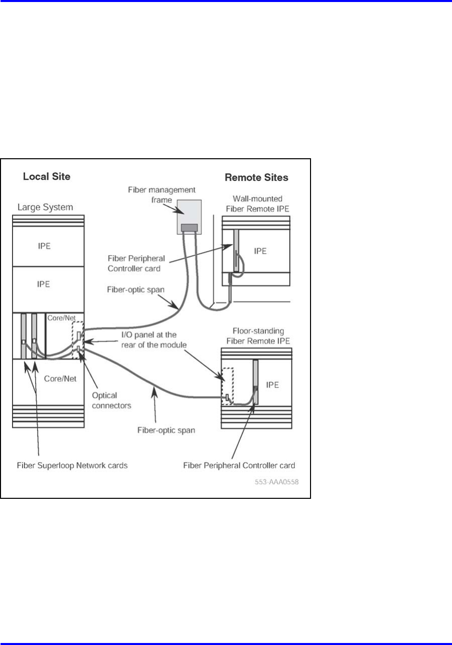
Configuration options 59
In a distributed system, subscriber connections are the same at local
IPE modules as they are at Remote IPE modules or small cabinets.
Furthermore, because Remote IPE equipment uses common and network
equipment from the local system, subscriber functions and features are
the same at local and remote sites.
Figure 19 "Large System to Remote IPE site" (page 59) illustrates the
fiber-optic connection between a local system and remote system.
Figure 19
Large System to Remote IPE site
Fiber Remote Multi-IPE Interface
The Fiber Remote Multi-IPE Interface links a Large System with one or
more Remote IPE sites to provide Meridian 1 Large System functionality.
Since the remote IPE system uses the Common Equipment and Network
Equipment of the associated local Large System, it can deliver the same
features and functionality as the local system. Figure 20 "Meridian 1 Large
Systemto Remote IPE connection over fiber-optic link" (page 60) illustrates
the fiber-optic connection between the local system and remote system.
Nortel Communication Server 1000
Communication Server 1000M and Meridian 1 Large System Overview
NN43021-110 02.05 Standard
30 September 2008
Copyright © 2003-2008 Nortel Networks
.
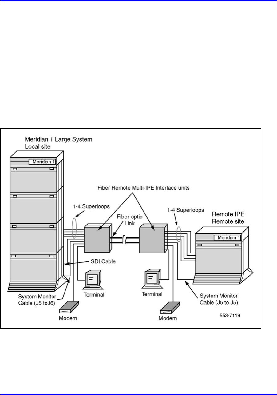
60 System architecture
The Fiber Remote Multi-IPE Interface links the local and remote systems
using a fiber-optic link over a single-mode optical fiber.
The Fiber Remote Multi-IPE Interface is available in four options which
allow the same configuration of the superloop connections at the remote
site as the configuration of the IPE modules at the local site:
•Single-mode fiber supporting four superloops
•Single-mode fiber supporting two superloops
•Multi-mode fiber supporting four superloops
•Multi-mode fiber supporting two superloops
Figure 20
Meridian 1 Large Systemto Remote IPE connection over fiber-optic link
For more information on Fiber Remote IPE, seeFiber Remote IPE
Fundamentals (NN43021-554), . For more information on the Fiber
Remote Multi-IPE Interface, see Fiber Remote Multi-IPE Interface
Fundamentals (N43021-556),.
Nortel Communication Server 1000
Communication Server 1000M and Meridian 1 Large System Overview
NN43021-110 02.05 Standard
30 September 2008
Copyright © 2003-2008 Nortel Networks
.
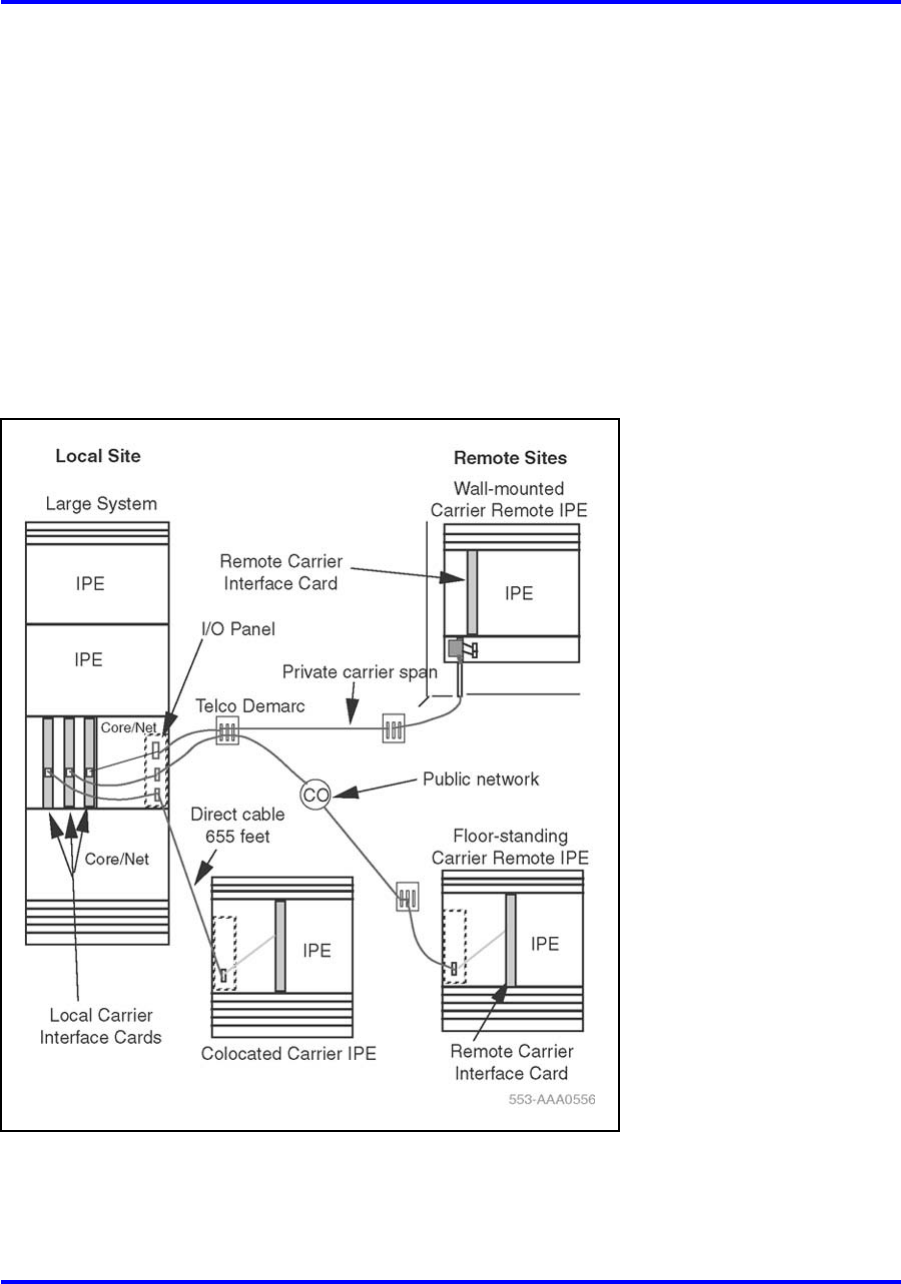
Configuration options 61
Carrier Remote IPE
The Carrier Remote IPE provides functionality by installing only IPE
modules and IPE cards at a distant site. The Remote IPE shares the
system’s Common and Network Equipment to provide the same functions
and features to remote subscribers that are available to local system
subscribers.
A floor-standing column or a wall-mounted cabinet Carrier Remote IPE
is installed at the remote site and is connected to the Meridian 1 Large
System using T1 or E1 connection. Figure 21 "Meridian 1 Large Systemto
Carrier Remote IPE links" (page 61) illustrates the connection between
the local system and remote system.
Figure 21
Meridian 1 Large Systemto Carrier Remote IPE links
For more information on Carrier Remote IPE, see Carrier Remote IPE
Fundamentals (NN43021-555),.
Nortel Communication Server 1000
Communication Server 1000M and Meridian 1 Large System Overview
NN43021-110 02.05 Standard
30 September 2008
Copyright © 2003-2008 Nortel Networks
.

62 System architecture
Branch Office
The Branch Office feature extends system features from a main office to
one or more branch offices.
A branch office is an MG 1000B Core connected to an IP PBX at the main
office over an enterprise IP network or over a WAN. This configuration
enables a secondary location to centralize the call processing of its
IP-based communications network. The Call Server at the main office
provides the call processing for the IP Phones in both the main office and
branch offices. The MG 1000B Core provides call processing functionality
to local digital telephones and analog devices. The MG 1000B Core also
provides digital and analog trunk access to the local Public Switched
Telephone Network (PSTN).
The branch office connects to the main office over Virtual Trunks on an
enterprise IP network or a WAN. The main office transmits and controls IP
Phone calls and IP network connections. If the main office fails to function,
or if there is a network outage, the MG 1000B Small System Controller
(SSC) provides service to the telephones located in the branch office. This
enables the IP Phones to survive the outage between the branch office
and the main office.
A branch office can be created as a new hardware configuration, or by
converting an existing Small System to a branch office. The functionality
is the same in both configurations.
For more information on the Branch Office feature, see Branch Office
Installation and Commissioning (NN43001-314),.
Geographic Redundancy
Geographic Redundancy enables a customer to duplicate the entire
redundant processing core of a CS 1000M SGor CS 1000M MGsystem
at a remote location, at any distance, over the customer WAN. The
duplicate core can then take over processing if the primary system fails
for any reason. Geographic Redundancy also offers automatic database
replication between main and standby systems to promote a smooth
transition. When this configuration is implemented, the customer enhances
the disaster recovery capability of the network and further secures
ultra-high reliability.
Note: Geographic Redundancy capabilities only apply to IP elements,
for example, to IP Phones and Media Gateways. Geographic
Redundancy does not apply to TDM elements.
For more information on the Geographic Redundancy feature, see System
Redundancy Fundamentals (NN43001-507),.
Nortel Communication Server 1000
Communication Server 1000M and Meridian 1 Large System Overview
NN43021-110 02.05 Standard
30 September 2008
Copyright © 2003-2008 Nortel Networks
.

63
.
List of terms
AC Alternating Current
analog A process that models information in the form of a continuously
varying parameter such as current, voltage, or phase.
analog signal A signal that varies in a continuous manner such as voice or
music. An analog signal can be contrasted with a digital signal,
which represents only discrete states. The signal emitted by a
data telephone has both analog and discrete characteristics.
architecture The interrelationship between the parts of a system; the
framework of a system.
backplane A printed circuit board that extends across the width of the card
cage and connects to the circuit card connectors.
battery backupSystem power furnished by standby batteries that are charged
by a charger. If commercial power fails, the batteries maintain
service for a limited period of time, determined by the size of the
batteries and the traffic on the system.
capacity The information-carrying ability of a telecommunications facility,
group, network, or system measured in bits per second (bps).
card cage A frame for holding circuit cards in a module; also called a card
chassis.
Nortel Communication Server 1000
Communication Server 1000M and Meridian 1 Large System Overview
NN43021-110 02.05 Standard
30 September 2008
Copyright © 2003-2008 Nortel Networks
.

64 List of terms
CBT Core Bus Terminator
CE Common Equipment
Central Office (CO)
The site where a telephone company terminates customer lines
and houses the switching equipment that interconnects those
lines.
central processing unit (CPU)
The main portion of a computer that contains the primary storage,
arithmetic and logic units, and the control unit (may also mean a
mainframe computer).
circuit cards Cards which carry the electronics for particular functions (such as
memory and switching functions). Most cards are housed in the
card cage in a module and connect to the backplane. Some cards
must be installed in dedicated slots in a card cage. (Also called
circuit packs or boards.)
CNI Core-to-Network Interface
CO See Central Office.
Common Equipment (CE)
A hardware subsystem that houses one or more central
processing units (CPUs), memory cards, disk drive units, and
service cards.
configuration A group of machines (hardware) that are interconnected and are
programmed to operate as a system.
CP Call Processor
cPCI®
Peripheral Component Interconnect. PCI provides a high-speed
data path between the CPU and peripheral devices (video, disk,
network, etc.).
Nortel Communication Server 1000
Communication Server 1000M and Meridian 1 Large System Overview
NN43021-110 02.05 Standard
30 September 2008
Copyright © 2003-2008 Nortel Networks
.

65
cPCI Transition card
Peripheral Component Interconnect Transition Card. Connects the
Core module cards to the 3PE cards in the Network modules.
CP PIV®
The successor to the Pentium II from Intel. Pentium IV refers to
the Pentium IV CPU chip.
CPU Central Processing Unit
DC Direct Current
diagnostic programs
Software routines used to test equipment and identify faulty
components
digital signal A signal made up of discrete, noncontinuous pulses whose
information is contained in the duration, periods, and/or amplitude
DTR Digitone Receiver
electromagnetic interference (EMI)
Unwanted electromagnetic static coupling, such as a ham
radio signal being heard on a television, or causing static noise
interference.
firmware A set of instruction sequences stored permanently in hardware
(ROM).
input/output (I/O)
Exchange between a machine and end-user equipment.
IODU/C Input/Output Disk Unit with CD-ROM
IPB Inter-Processor Bus
IPE Intelligent Peripheral Equipment
Nortel Communication Server 1000
Communication Server 1000M and Meridian 1 Large System Overview
NN43021-110 02.05 Standard
30 September 2008
Copyright © 2003-2008 Nortel Networks
.

66 List of terms
ISDN Integrated Services Digital Network
line A communication channel or circuit; an electrical path.
loop A bidirectional path between network equipment and peripheral
equipment.
module power supplies
Individual power units that generate the different DC voltages
required by the cards installed in each module.
Network Equipment
A hardware subsystem that provides digital multiplexed switching
for voice, data, and signaling paths.
office data Office data represents system configuration data, peripheral
equipment data, and transient data (temporary) used for call
processing.
PCM Pulse Code Modulation.
pedestal The bottom element in a column. Each pedestal houses a blower
unit, an air filter, the PDU (which contains the column circuit
breakers), and the system monitor.
power distribution unit (PDU)
Input power for CS 1000M Large Systemand Meridian 1 Large
Systemare brought into the pedestal to the PDU. The PDU
distributes input power to the column.
Pulse Code Modulation (PCM)
A modulation technique where the signal is converted from an
analog to a digital format by sampling the signal at periodic
intervals and digitizing the amplitude into a finite number of
discrete levels
random-access memory (RAM)
A storage system or computer memory accessible by the user for
either storing or retrieving information. RAM is volatile memory.
Nortel Communication Server 1000
Communication Server 1000M and Meridian 1 Large System Overview
NN43021-110 02.05 Standard
30 September 2008
Copyright © 2003-2008 Nortel Networks
.

67
read-only memory (ROM)
Storage system or computer memory that is "burned into" the
microprocessor chip and can be read, but not written to or
modified. ROM is nonvolatile memory.
redundancy The duplication of software, or hardware, or both (such as
redundant CPUs) used as a standby in case one fails.
SDI Serial Data Interface. A family of cards equipped with SDI ports
provide the I/O interface for the CS 1000M Large Systemand
Meridian 1 Large System.
software A set of programmed instruction sequences stored either as
resident programs in system memory or as nonresident programs
stored on disk and loaded into memory when needed.
software generic
A term used to identify the system software. Each software
generic has a series of releases, such as Release 25.
system monitor
A microprocessor-based circuit card that controls and monitors
the status of cooling equipment and power-related hardware and
functions.
system utility card
Provides an interface between the security device and the
computer.
TDS Tone and Digit Switch
Time Compression Multiplexing (TCM)
The combination of two or more information channels into a single
transmission channel by assigning each information channel an
exclusive periodic transmission time interval.
TN Terminal Number
Nortel Communication Server 1000
Communication Server 1000M and Meridian 1 Large System Overview
NN43021-110 02.05 Standard
30 September 2008
Copyright © 2003-2008 Nortel Networks
.

68 List of terms
top cap A top cap is mounted on the top module of each column. It
provides airflow exits, EMI/RFI shielding, I/O cable entry and exit,
and overhead cable-rack mounting. The top cap covers thermal
sensor assemblies for the column.
trunk A single circuit between two points, both of which are switching
centers or individual distribution points.
universal equipment module (UEM)
A modular, self-contained hardware cabinet that houses a card
cage, power supply, backplane, circuit cards, and other basic
equipment. When equipped, the UEM becomes a specific type of
module, such as a CPU module or Network module.
UPS Universal Power Supply
VAC Voltage Alternating Current
VDC Voltage Direct Current
Nortel Communication Server 1000
Communication Server 1000M and Meridian 1 Large System Overview
NN43021-110 02.05 Standard
30 September 2008
Copyright © 2003-2008 Nortel Networks
.

Nortel Communication Server 1000
Communication Server 1000M and Meridian 1 Large System
Overview
Copyright © 2003-2008 Nortel Networks
All Rights Reserved.
Release: 5.5
Publication: NN43021-110
Document status: Standard
Document revision: 02.05
Document release date: 30 September 2008
To provide feedback or to report a problem in this document, go to www.nortel.com/documentfeedback.
www.nortel.com
Sourced in Canada
LEGAL NOTICE
While the information in this document is believed to be accurate and reliable, except as otherwise expressly agreed to in writing
NORTEL PROVIDES THIS DOCUMENT "AS IS" WITHOUT WARRANTY OR CONDITION OF ANY KIND, EITHER EXPRESS
OR IMPLIED. The information and/or products described in this document are subject to change without notice.
Nortel, Nortel (Logo), the Globemark, SL-1, Meridian 1, and Succession are trademarks of Nortel Networks.
All other trademarks are the property of their respective owners.
