Nortel Networks Nn43001 301 Users Manual ISDN Primary Rate Interface Installation And Commissioning
NN43001-301 to the manual 8f6f8d6a-530b-44dd-8d87-38c31988129f
2015-01-26
: Nortel-Networks Nortel-Networks-Nn43001-301-Users-Manual-346480 nortel-networks-nn43001-301-users-manual-346480 nortel-networks pdf
Open the PDF directly: View PDF ![]() .
.
Page Count: 306 [warning: Documents this large are best viewed by clicking the View PDF Link!]
- ISDN Primary Rate InterfaceInstallation and Commissioning
- Contents
- New in this release
- How to get help
- Introduction
- ISDN Primary Rate Interface equipment overview
- Contents
- Introduction
- Primary Rate Interface (PRI) hardware requirements
- ISDN Signaling Link (ISL) hardware
- D-Channel Handler description
- NT6D11 DCH
- QPC757 DCH
- NT6D80 MSDL
- NTBK51 Downloadable D-Channel Daughterboard
- Standard PRI cards
- NT8D72 PRI2
- QPC720 PRI
- Disk drive hardware
- NT5D97 Dual-port DTI2/PRI2 card
- NT5D12 Dual-port DTI/PRI
- DCH installation
- NTBK51 DDCH installation and removal
- MSDL installation for all systems
- NT8D72 and QPC720 PRI card installation
- NT5D97 Dual-port DTI2/PRI2 installation and removal
- NT5D12 Dual-port DTI/PRI card installation
- Clock Controller description and installation
- ISL installation
- Echo canceller installation
- 1.5 Mb PRI implementation
- 1.5 Mb DTI implementation
- 1.5 Mb ISL implementation
- 2.0 Mb DTI implementation
- 2.0 Mb PRI implementation
- 2.0 Mb ISL implementation
- Nonstandard cables
- Contents
- Introduction
- NT5K40AA, NT5K41AA, NT5K86AA
- NT8D7206, NT8D7207
- QCAD128
- QCAD129
- QCAD133
- NT8D7205
- QCAD328
- NT8D74 Clock Controller to InterGroup cable
- NT8D75 Clock Controller to Clock Controller cable
- NT8D79 PRI/DTI to Clock Controller cable
- NT8D83 PRI/DTI to I/O cable
- NT8D85 Network to IPE cable
- NT8D86 Network to I/O cable
- NT8D97AX PRI/DTI I/O to MDF cable
- NT9J93AD PRI/DTI Echo Canceller to I/O cable
- NTND26 PRI to MSDL cables
- NTND27 MSDL to I/O panel cables
- NTND98 PRI to I/O panel cables
- Figures
- Figure 1 PRI hardware (shown without downloadable PRI and DCH cards)
- Figure 2 NT6D11 DCH faceplate layout
- Figure 3 QPC757 DCH faceplate layout
- Figure 4 NT6D80 MSDL faceplate layout
- Figure 5 NT8D72 PRI faceplate layout
- Figure 6 Clock controller primary and secondary tracking
- Figure 7 QPC720 PRI faceplate layout
- Figure 8 NT5D97 faceplate
- Figure 9 NTCK45AA
- Figure 10 NT8D7217
- Figure 11 NTCK78AA
- Figure 12 NTCK79AA
- Figure 13 NTCG03AA/AB/AC/AD
- Figure 14 NTCK46AA/AB/AC/AD
- Figure 15 NTCK80AA/AB/AC/AD
- Figure 16 DDP2 cable for systems with an I/O panel
- Figure 17 DDP2 cable for systems without an I/O panel
- Figure 18 Clock Controller primary and secondary tracking
- Figure 19 Clock Controller - Option 1
- Figure 20 Clock Controller - Option 2
- Figure 21 Clock Controller - Option 3
- Figure 22 Clock Controller - Option 4
- Figure 23 NT5D12 faceplate - general view
- Figure 24 DDP faceplate - detailed view
- Figure 25 NT5D16AA
- Figure 26 NTCG03AA, NTCG03AB, NTCG03AC, or NTCG03AD
- Figure 27 NTCK46AA, NTCK46AB, NTCK46AC, NTCK46AD
- Figure 28 NTCK80AA, NTCK80AB, NTCK80AC, NTCK80AD
- Figure 29 DDP cable for systems with an I/O panel
- Figure 30 Clock Controller primary and secondary tracking
- Figure 31 Clock Controller - Option 1
- Figure 32 Clock Controller - Option 2
- Figure 33 Clock Controller - Option 3
- Figure 34 Clock Controller - Option 4
- Figure 35 NT6D11 DIP switches
- Figure 36 NT6D11 DCH with ISL high-speed programming jumper settings
- Figure 37 NT6D11 DCH with ISL low-speed programming jumper settings
- Figure 38 QPC757 option and PRI/ISL high-speed programming switch settings
- Figure 39 QPC757 option and PRI/ISL low-speed programming switch settings
- Figure 40 MSDL card layout
- Figure 41 NT8D72(Half Group cabling) on Half and Single Group systems without an echo canceller
- Figure 42 NT8D72 (Half Group cabling) for Half and Single Group systems, with an echo canceller
- Figure 43 NT8D72 (Single Group cabling) for Half and Single Group systems, without an echo canceller
- Figure 44 NT8D72 (Single Group cabling) for Half and Single Group systems, with an echo canceller
- Figure 45 NT8D72 (Multi Group cabling) for Multi Group systems without an echo canceller
- Figure 46 NT8D72 (Multi Group cabling) for Multi Group systems with an echo canceller
- Figure 47 QPC720 (Half Group cabling) for Multi Group systems without an echo canceller
- Figure 48 QPC720 (Half Group cabling) for Multi Group systems with an echo canceller
- Figure 49 QPC720 (Single Group cabling) for Multi Group systems without an echo canceller
- Figure 50 QPC720 (Single Group cabling) for Multi Group systems with an echo canceller
- Figure 51 QPC720 Multi Group cabling without an echo canceller
- Figure 52 QPC720 Multi Group cabling with an echo canceller
- Figure 53 NT8D72AA, NT8D72AB, NT8D72BA PRI DIP switch settings for Large Systems
- Figure 54 QPC720 switch settings for Half and Single Group systems
- Figure 55 DIP switches for NT5D97AA/AB
- Figure 56 Dip switches locations for NT5D97AD
- Figure 57 Switch functional areas on the NT5D12
- Figure 58 NT5D12 switch default settings
- Figure 59 Hierarchical Synchronization
- Figure 60 Example 1, Isolated Private Network
- Figure 61 Example 2, Isolated Private Network with Secondary Reference Clock
- Figure 62 Example 3, Clocking Hierarchy referenced to a Public Network Master Clock
- Figure 63 Example 4, Alternate Clocking from the same CO
- Figure 64 Example 5, digital connection to the CO
- Figure 65 Example 6, Complex Isolated Private Network
- Figure 66 Example 7, Network Clocking with MUX
- Figure 67 NT6D11AB, NT6D11AD DCHI with ISL high-speed programming jumper settings
- Figure 68 NT6D11AB, NT6D11AD DCHI with ISL low-speed programming jumper settings
- Figure 69 MSDL/ISL settings
- Figure 70 ISL in shared mode
- Figure 71 ISL dedicated mode, using leased line
- Figure 72 ISL dedicated mode: using dialup Hayes Smartmodem 2400
- Figure 73 ISL dedicated mode, using dialup Hayes Smartmodem 2400
- Figure 74 ISL dedicated mode: using PRI/DTI trunk
- Figure 75 PRI to echo canceller cabling
- Figure 76 NTRB21 TMDI card faceplate
- Figure 77 NTAK09 DTI/PRI circuit card
- Figure 78 NTAK20 daughterboard installation on the NTRB21
- Figure 79 Daughterboard installation on the NTAK09
- Figure 80 ISL in dedicated mode using leased line
- Figure 81 ISL in dedicated mode using dialup modem
- Figure 82 2.0 Mb DTI cabling
- Figure 83 NTAK79 with switch locations
- Figure 84 NTAK79 cabling
- Figure 85 NTBK50 with switch locations
- Figure 86 Daughterboard installation
- Figure 87 NTBK50 cabling
- Figure 88 ISL in shared mode
- Figure 89 ISL in dedicated mode using leased line
- Figure 90 ISL in dedicated mode using dialup modem
- Tables
- Table 1 Meridian 1 systems to CS 1000 systems
- Table 2 NT8D72 PRI External connectors
- Table 3 NT8D72AB and NT8D72BA PRI: Cables and cable lengths
- Table 4 QPC720 PRI external connectors
- Table 5 QPC720 PRI cables and cable lengths
- Table 6 DCH/MSDL Receiver Ready control signals
- Table 7 External connectors and LEDs
- Table 8 NT5D97 DDP2 power requirements
- Table 9 NTCK45AA cable pins
- Table 10 NT8D7217 cable pins
- Table 11 NTCK78AA cable pins
- Table 12 NTCK79AA cable pins
- Table 13 Clock Controller options - summary
- Table 14 Clock Controller options - description
- Table 15 DCHI/MSDL Receiver Ready control signals
- Table 16 External connectors and LEDs
- Table 17 DDP power requirements
- Table 18 NT5D16AA cable pins
- Table 19 Clock Controller options- summary
- Table 20 Clock Controller options - description
- Table 21 Protocol selection switch settings
- Table 22 Port 0 settings
- Table 23 Port 1 settings
- Table 24 Port 0 mode selection
- Table 25 Port 1 mode selection
- Table 26 Port address switch settings for ISDN
- Table 27 D-channel port address switch settings for PRI
- Table 28 MSDL switch settings
- Table 29 Cable for the NT8D72 PRI card for Half and Single Group systems
- Table 30 Cable for the NT8D72 PRI card for Multi Group systems
- Table 31 Cable for the QPC720 PRI card for Half and Multi Group systems
- Table 32 Cable for the QPC720 PRI card on Multi Group systems
- Table 33 NT8D72 and QPC720 PRI transmission equalization switch settings for Large Systems
- Table 34 Shelf and slot location of NT8D72 and QPC720 for Half Group and Single Group systems
- Table 35 NT5D97AA/AB loops configuration
- Table 36 NT5D97AD loops configuration
- Table 37 DIP switch settings for NT5D97AA/AB
- Table 38 Impedance level and loop mode switch settings
- Table 39 Impedance level and loop mode switch settings
- Table 40 Trunk interface line build out switch settings
- Table 41 Trunk interface impedance switch settings
- Table 42 Ring ground switch settings
- Table 43 DCH mode and address switch settings
- Table 44 NTBK51AA daughterboard addressselect switch settings
- Table 45 DIP switch settings for NT5D97AD
- Table 46 General purpose switches for NT5D97AD
- Table 47 TX mode switches for NT5D97AD
- Table 48 LBO switches for NT5D97AD
- Table 49 Receiver interface switches for NT5D97AD
- Table 50 Trunk 1 switches
- Table 51 Ring ground switch for NT5D97AD
- Table 52 NTBK51AA DCH switches for NT5D97AD
- Table 53 Switch settings for MSDL external card
- Table 54 Switch setting for MSDL external card
- Table 55 General purpose switch settings
- Table 56 Trunk interface transmission mode switch settings
- Table 57 Trunk interface line build out switch settings
- Table 58 Trunk interface receiver impedance switch settings
- Table 59 Ring ground switch settings
- Table 60 DCH mode and address select switch settings
- Table 61 NTBK51AA daughterboard address select switch settings
- Table 62 Node categories and stratum levels
- Table 63 Performance impact of one slip on service type
- Table 64 Clock Controller shelves and slots
- Table 65 Clock Controller switch settings for QPC471 vintage H
- Table 66 Clock Controller switch settings for QPC775
- Table 67 Clock Controller switch settings for NTRB53
- Table 68 Active and stored profiles of the autodial or originating modem
- Table 69 Active and stored profiles of the auto answer or terminating modem
- Table 70 PRI-to-Echo canceller - pin assignments
- Table 71 Required circuit cards
- Table 72 Media Gateway and Media Gateway Expansion slot assignments
- Table 73 Clock controller LEDs
- Table 74 Shelf slot assignments for NTRB21, NTAK09, and NTAK20
- Table 75 NTAK09 switch settings
- Table 76 DS-1 line interface pinout for NTBK04 cable
- Table 77 DTI hardware
- Table 78 NTAK09 switch settings
- Table 79 DS-1 line interface pinout for NTBK04 cable
- Table 80 Leased line requirements
- Table 81 Dial-up modem requirements
- Table 82 NTAK02 switch setting
- Table 83 NTAK02 jumper settings
- Table 84 Switch S1
- Table 85 Switch S2
- Table 86 Switch S3
- Table 87 Switch S4
- Table 88 NTBK05DA pinouts
- Table 89 NTBK05CA pinouts
- Table 90 2.0 Mb DTI pads
- Table 91 2.0 Mb PRI hardware requirement
- Table 92 Switch SW1
- Table 93 Switch SW2
- Table 94 Switch SW3
- Table 95 Switch SW4
- Table 96 NTBK05DA pinouts
- Table 97 NTBK05CA pinouts
- Table 98 Switch SW1
- Table 99 Switch SW2
- Table 100 Switch SW3
- Table 101 NTBK05DA pinouts
- Table 102 NTBK05CA pinouts
- Table 103 Pad values
- Table 104 NTAK02 switch settings
- Table 105 NTAK02 jumper settings
- Table 106 Configuring basic ISL capability
- Table 107 NT5K40AA, NT5K41AA, NT5K86AA wire list
- Table 108 NT8D7206, NT8D7207 wire list
- Table 109 QCAD128 wire list
- Table 110 QCAD129 wire list
- Table 111 QCAD133 wire list
- Table 112 NT8D7205 wire list
- Table 113 QCAD328 wire list
- Procedures
- Procedure 1 Install the NT6D11AB, NT6D11AE, NT6D11AF DCH
- Procedure 2 Remove the NT6D11AB, NT6D11AE, NT6D11AF DCH
- Procedure 3 Install the QPC757 DCHI
- Procedure 4 Remove the QPC757 DCH
- Procedure 5 Install the NTBK51 on the NT5D97 dual-port DTI2/PRI2 card
- Procedure 6 Remove the NTBK51 from the NT5D97 dual-port DTI2/PRI2 card
- Procedure 7 Install the NTBK51 DDCH on the NT5D12 dual-port DTI/PRI
- Procedure 8 Remove the NTBK51 from the NT5D12 dual-port DTI/PRI card
- Procedure 9 Install the MSDL card
- Procedure 10 Replace the MSDL card
- Procedure 11 Install the NT8D72 and QPC720 PRI on Large Systems
- Procedure 12
- Procedure 13 Install an additional network shelf on Half Group and Single Group systems
- Procedure 14 Install the NT5D97 on Large Systems
- Procedure 15 Remove the NT5D97 from Large Systems
- Procedure 16 Install the NT5D12 on Large Systems
- Procedure 17 Remove the NT5D12 DDP
- Procedure 18 Install a clock controller for Half Group and Single Group Systems.
- Procedure 19 Install a Clock Controller on a Single Group and Multi Group System
- Procedure 20 Remove old equipment
- Procedure 21 Installing new equipment
- Procedure 22 Install ISL in dedicated mode
- Procedure 23 Install ISL in shared mode
- Procedure 24 Mounting the NTAK20 daughterboard on the NTRB21
- Procedure 25 Inserting the NTRB21 TMDI card
- Procedure 26 Removing the NTRB21 TMDI card
- Procedure 27 Mounting the daughterboards on the NTAK09
- Procedure 28 Removing the daughterboards from the NTAK09
- Procedure 29 Installing the NTAK09
- Procedure 30 Connecting the cables
- Procedure 31 Enabling the NTRB21 TMDI card
- Procedure 32 Enabling the NTAK09 DTI/PRI card
- Procedure 33 Implementing basic PRI
- Procedure 34 Enabling the NTRB21 TMDI card
- Procedure 35 Enabling the NTAK09 card
- Procedure 36 Implementing DTI
- Procedure 37 Installing ISL hardware
- Procedure 38 Implementing dedicated mode
- Procedure 39 Connecting the cables
- Procedure 40 Connecting the cables
- Procedure 41 Inspecting the NTBK50 circuit card
- Procedure 42 Installing the NTAK02
- Procedure 43 Setting up the D-channel
- Contents

Nortel Communication Server 1000
ISDN Primary Rate Interface
Installation and Commissioning
NN43001-301
.
Document status: Standard
Document version: 02.03
Document date: 7 December 2007
Copyright © 2003-2007, Nortel Networks
All Rights Reserved.
Sourced in Canada
LEGAL NOTICE
While the information in this document is believed to be accurate and reliable, except as otherwise expressly agreed
to in writing NORTEL PROVIDES THIS DOCUMENT "AS IS" WITHOUT WARRANTY OR CONDITION OF ANY
KIND, EITHER EXPRESS OR IMPLIED. The information and/or products described in this document are subject
to change without notice.
Nortel, the Nortel Logo, the Globemark, SL-1, Meridian 1, and Succession are trademarks of Nortel Networks.
All other trademarks are the property of their respective owners.

3
Contents
New in this release 9
Other 9
Revision History 9
How to get help 11
Getting help from the Nortel web site 11
Getting help over the telephone from a Nortel Solutions Center 11
Getting help from a specialist by using an Express Routing Code 11
Getting help through a Nortel distributor or reseller 12
Introduction 13
Subject 13
Applicable systems 13
Intended audience 14
Related information 14
ISDN Primary Rate Interface equipment overview 15
Contents 15
Introduction 17
Primary Rate Interface (PRI) hardware requirements 17
ISDN Signaling Link (ISL) hardware 18
D-Channel Handler description 20
NT6D11 DCH 20
QPC757 DCH 21
NT6D80 MSDL 23
NTBK51 Downloadable D-Channel Daughterboard 25
Standard PRI cards 25
NT8D72 PRI2 25
QPC720 PRI 30
Disk drive hardware 34
NT5D97 Dual-port DTI2/PRI2 card 34
NT5D12 Dual-port DTI/PRI 57
DCH installation 79
Contents 79
Install the NT6D11AB, NT6D11AE, NT6D11AF DCH 79
Set up the NT6D11AB, NT6D11AE, NT6D11AF DCHI 80
Nortel Communication Server 1000
ISDN Primary Rate Interface Installation and Commissioning
NN43001-301 02.03 Standard
Release 5.5 7 December 2007
Copyright © 2003-2007, Nortel Networks
.

4Contents
Install the NT6D11AB, NT6D11AE, NT6D11AF DCHI 85
Remove the NT6D11AB, NT6D11AE, NT6D11AF DCH 86
Install the QPC757 DCH 87
NTBK51 DDCH installation and removal 91
Contents 91
Introduction 91
Install NTBK51 DDCH on NT5D97 dual-port DTI2/PRI2 card 91
Remove NTBK51 DDCH from NT5D97 dual-port DTI2/PRI2 card 92
Install NTBK51 DDCH on NT5D12 dual-port DTI/PRI 93
Remove NTBK51 DDCH from NT5D12 dual-port DTI/PRI 94
MSDL installation for all systems 95
Contents 95
Install the MSDL 95
Replace the MSDL 98
NT8D72 and QPC720 PRI card installation 101
Contents 101
Introduction 101
PRI circuit pack locations 101
Cable requirements 102
Switch settings 120
Install NT8D72 and QPC720 PRI cards on Large Systems 123
Remove NT8D72 and QPC720 PRI cards from Large Systems 124
Install an additional network shelf 125
NT5D97 Dual-port DTI2/PRI2 installation and removal 127
Contents 127
Introduction 127
NT5D97 circuit card locations 127
Port definitions 128
Case Scenarios for replacing a digital trunk NT8D72BA, QPC536E, or NTCK43
by a DDP2 card 128
NT5D97AA/AB DIP switch settings 129
NT5D97AD DIP switch settings 134
Install the NT5D97 DDP2 139
Remove the NT5D97 DDP2 140
Configure the NT5D97 DDP2 141
NT5D12 Dual-port DTI/PRI card installation 143
Contents 143
Introduction 143
NT5D12 circuit card locations 143
Port definitions 144
Scenarios for replacement of a digital trunk card (QPC720/QPC472) by a DDP
card 144
Nortel Communication Server 1000
ISDN Primary Rate Interface Installation and Commissioning
NN43001-301 02.03 Standard
Release 5.5 7 December 2007
Copyright © 2003-2007, Nortel Networks
.

Contents 5
NT5D12 switch settings 145
Install the NT5D12 DDP 150
Remove the NT5D12 DDP 152
Configure the NT5D12 DDP 153
Clock Controller description and installation 155
Contents 155
Introduction 156
Description 156
Installation procedures 168
ISL installation 179
Contents 179
ISL configurations 179
DCHI switch settings 180
MSDL switch settings 181
Dedicated mode using leased line 183
Dedicated mode using dialup modem 184
ISL installation 189
Echo canceller installation 191
Contents 191
Introduction 191
Echo canceller operating parameters 191
Echo canceller initialization procedures 191
PRI to Echo canceller pin assignments 192
Electromagnetic Interference 192
1.5 Mb PRI implementation 195
Contents 195
Overview 195
Hardware requirements 195
Hardware description 196
Install PRI hardware 203
1.5 Mb DTI implementation 219
Contents 219
Overview 219
Hardware requirements 219
Hardware description 220
Install DTI hardware 220
Software enable the DTI/PRI cards 222
1.5 Mb ISL implementation 227
Contents 227
Overview 227
Hardware requirements 227
Basic ISL implementation 232
Nortel Communication Server 1000
ISDN Primary Rate Interface Installation and Commissioning
NN43001-301 02.03 Standard
Release 5.5 7 December 2007
Copyright © 2003-2007, Nortel Networks
.

6Contents
2.0 Mb DTI implementation 237
Contents 237
Overview 237
Hardware requirements 237
NTAK10 2.0 Mb DTI card 238
Install DTI hardware 238
DTI software implementation 241
2.0 Mb PRI implementation 257
Contents 257
Overview 257
Hardware requirements 257
Hardware description 258
Install the NTAK79 PRI card 261
Install the NTBK50 PRI card 266
PRI software implementation 272
2.0 Mb ISL implementation 283
Contents 283
Overview 283
ISL hardware requirements 283
ISL hardware installation 286
ISL software implementation 288
Nonstandard cables 295
Contents 295
Introduction 296
NT5K40AA, NT5K41AA, NT5K86AA 296
NT8D7206, NT8D7207 296
QCAD128 297
QCAD129 298
QCAD133 298
NT8D7205 299
QCAD328 300
NT8D74 Clock Controller to InterGroup cable 301
NT8D75 Clock Controller to Clock Controller cable 301
NT8D79 PRI/DTI to Clock Controller cable 301
NT8D83 PRI/DTI to I/O cable 301
NT8D85 Network to IPE cable 302
NT8D86 Network to I/O cable 302
NT8D97AX PRI/DTI I/O to MDF cable 302
NT9J93AD PRI/DTI Echo Canceller to I/O cable 303
NTND26 PRI to MSDL cables 303
NTND27 MSDL to I/O panel cables 303
NTND98 PRI to I/O panel cables 303
Nortel Communication Server 1000
ISDN Primary Rate Interface Installation and Commissioning
NN43001-301 02.03 Standard
Release 5.5 7 December 2007
Copyright © 2003-2007, Nortel Networks
.

Contents 7
Procedures
Procedure 1 Install the NT6D11AB, NT6D11AE, NT6D11AF DCH 85
Procedure 2 Remove the NT6D11AB, NT6D11AE, NT6D11AF DCH 86
Procedure 3 Install the QPC757 DCHI 87
Procedure 4 Remove the QPC757 DCH 90
Procedure 5 Install the NTBK51 on the NT5D97 dual-port DTI2/PRI2
card 92
Procedure 6 Remove the NTBK51 from the NT5D97 dual-port DTI2/PRI2
card 93
Procedure 7 Install the NTBK51 DDCH on the NT5D12 dual-port
DTI/PRI 94
Procedure 8 Remove the NTBK51 from the NT5D12 dual-port DTI/PRI
card 94
Procedure 9 Install the MSDL card 95
Procedure 10 Replace the MSDL card 98
Procedure 11 Install the NT8D72 and QPC720 PRI on Large Systems 123
Procedure 12 124
Procedure 13 Install an additional network shelf on Half Group and Single
Group systems 125
Procedure 14 Install the NT5D97 on Large Systems 139
Procedure 15 Remove the NT5D97 from Large Systems 141
Procedure 16 Install the NT5D12 on Large Systems 151
Procedure 17 Remove the NT5D12 DDP 152
Procedure 18 Install a clock controller for Half Group and Single Group
Systems. 171
Procedure 19 Install a Clock Controller on a Single Group and Multi Group
System 173
Procedure 20 Remove old equipment 175
Procedure 21 Installing new equipment 176
Procedure 22 Install ISL in dedicated mode 189
Procedure 23 Install ISL in shared mode 189
Procedure 24 Mounting the NTAK20 daughterboard on the NTRB21 203
Procedure 25 Inserting the NTRB21 TMDI card 205
Procedure 26 Removing the NTRB21 TMDI card 206
Procedure 27 Mounting the daughterboards on the NTAK09 206
Procedure 28 Removing the daughterboards from the NTAK09 207
Procedure 29 Installing the NTAK09 209
Procedure 30 Connecting the cables 209
Procedure 31 Enabling the NTRB21 TMDI card 210
Procedure 32 Enabling the NTAK09 DTI/PRI card 211
Procedure 33 Implementing basic PRI 212
Procedure 34 Enabling the NTRB21 TMDI card 222
Procedure 35 Enabling the NTAK09 card 222
Procedure 36 Implementing DTI 223
Procedure 37 Installing ISL hardware 230
Procedure 38 Implementing dedicated mode 232
Procedure 39 Connecting the cables 240
Procedure 261
Procedure 40 Connecting the cables 264
Nortel Communication Server 1000
ISDN Primary Rate Interface Installation and Commissioning
NN43001-301 02.03 Standard
Release 5.5 7 December 2007
Copyright © 2003-2007, Nortel Networks
.

8Contents
Procedure 266
Procedure 41 Inspecting the NTBK50 circuit card 266
Procedure 42 Installing the NTAK02 286
Procedure 43 Setting up the D-channel 287
Nortel Communication Server 1000
ISDN Primary Rate Interface Installation and Commissioning
NN43001-301 02.03 Standard
Release 5.5 7 December 2007
Copyright © 2003-2007, Nortel Networks
.

9
New in this release
There have been no updates to the document in this release
Other Revision History
December 2007 Standard 02.03. This document has been up-issued to support
Communication Server Release 5.5.
August 2007 Standard 01.03. This document has been up-issued to support a
change request.
June 2007 Standard 01.02. This document is up-issued to remove the Nortel
Networks Confidential statement.
May 2007 Standard 01.01. This document is issued to support Communication
Server 1000 Release 5.0. This document contains information
previously contained in the following legacy document, now retired:
ISDN Primary Rate Interface Installation and Commissioning
(NN43001-301). No new content has been added for Communication
Server 1000 Release 5.0. All references to Communication Server
1000 Release 4.5 are applicable to Communication Server 1000
Release 5.0.
August 2005 Standard 3.00. This document is up-issued to support
Communication Server 1000 Release 4.5.
September 2004 Standard 2.00. This document is up-issued for Communication
Server 1000 Release 4.0.
October 2003 Standard 1.00. This document is a new technical document for
Succession 3.0. It was created to support a restructuring of the
Documentation Library, which resulted in the merging of multiple
legacy technical documents. This new document consolidates
information previously contained in the following legacy documents,
now retired:
•ISDN Primary Rate Interface: Installation (553-2901-201)
•1.5Mb DTI/PRI: Description, Installation and Maintenance
(553-3011-310) (Content from 1.5Mb DTI/PRI: Description,
Installation and Maintenance (553-3011-310) also appears in
ISDN Primary Rate Interface Maintenance (NN43001-717).)
Nortel Communication Server 1000
ISDN Primary Rate Interface Installation and Commissioning
NN43001-301 02.03 Standard
Release 5.5 7 December 2007
Copyright © 2003-2007, Nortel Networks
.

10 New in this release
•2.0Mb DTI/PRI: Description, Installation and Maintenance
(553-3011-315) (Content from 2.0Mb DTI/PRI: Description,
Installation and Maintenance (553-3011-315) also appears in
ISDN Primary Rate Interface Maintenance (NN43001-717).)
Nortel Communication Server 1000
ISDN Primary Rate Interface Installation and Commissioning
NN43001-301 02.03 Standard
Release 5.5 7 December 2007
Copyright © 2003-2007, Nortel Networks
.

11
How to get help
This chapter explains how to get help for Nortel products and services.
Getting help from the Nortel web site
The best way to get technical support for Nortel products is from the Nortel
Technical Support web site:
http://www.nortel.com/support
This site provides quick access to software, documentation, bulletins, and
tools to address issues with Nortel products. From this site, you can:
•download software, documentation, and product bulletins
•search the Technical Support Web site and the Nortel Knowledge Base
for answers to technical issues
•sign up for automatic notification of new software and documentation
for Nortel equipment
•open and manage technical support cases
Getting help over the telephone from a Nortel Solutions Center
If you do not find the information you require on the Nortel Technical Support
web site, and you have a Nortel support contract, you can also get help over
the telephone from a Nortel Solutions Center.
In North America, call 1-800-4NORTEL (1-800-466-7835).
Outside North America, go to the following web site to obtain the telephone
number for your region:
http://www.nortel.com/callus
Getting help from a specialist by using an Express Routing Code
To access some Nortel Technical Solutions Centers, you can use an Express
Routing Code (ERC) to quickly route your call to a specialist in your Nortel
product or service. To locate the ERC for your product or service, go to:
Nortel Communication Server 1000
ISDN Primary Rate Interface Installation and Commissioning
NN43001-301 02.03 Standard
Release 5.5 7 December 2007
Copyright © 2003-2007, Nortel Networks
.

12 How to get help
http://www.nortel.com/erc
Getting help through a Nortel distributor or reseller
If you purchased a service contract for your Nortel product from a distributor
or authorized reseller, contact the technical support staff for that distributor
or reseller.
Nortel Communication Server 1000
ISDN Primary Rate Interface Installation and Commissioning
NN43001-301 02.03 Standard
Release 5.5 7 December 2007
Copyright © 2003-2007, Nortel Networks
.

13
Introduction
This document is a global document. Contact your system supplier or your
Nortel representative to verify that the hardware and software described
are supported in your area.
Subject
Note on legacy products and releases
This technical document contains information about systems, components,
and features that are compatible with Nortel Communication Server
1000 Release 5.5 software. For more information on legacy products
and releases, click the Technical Documentation link under Support &
Training on the Nortel home page:
www.nortel.com
Applicable systems
This document applies to the following systems:
•Communication Server 1000E (CS 1000E) CP PII, CP PIV and CP PM
•Communication Server 1000M Single Group (CS 1000M SG) CP PII,
CP PIV
•Communication Server 1000M Multi Group (CS 1000M MG) CP PII,
CP PIV
•Meridian 1 PBX 11C Chassis
•Meridian 1 PBX 11C Cabinet
•Meridian 1 PBX 61C CP PII, CP PIV
•Meridian 1 PBX 81C CP PII, CP PIV
Note: When upgrading software, memory upgrades may be required on
the Signaling Server, the Call Server, or both.
Nortel Communication Server 1000
ISDN Primary Rate Interface Installation and Commissioning
NN43001-301 02.03 Standard
Release 5.5 7 December 2007
Copyright © 2003-2007, Nortel Networks
.
14 Introduction
System migration
When particular Meridian 1 systems are upgraded to run CS 1000 software
and configured to include a Signaling Server, they become CS 1000
systems. Table 1 "Meridian 1 systems to CS 1000 systems" (page 14) lists
each Meridian 1 system that supports an upgrade path to a CS 1000 system.
Table 1
Meridian 1 systems to CS 1000 systems
This Meridian 1 system... Maps to this CS 1000 system
Meridian 1 PBX 11C Chassis CS 1000E
Meridian 1 PBX 11C Cabinet CS 1000E
Meridian 1 PBX 61C CS 1000M Single Group
Meridian 1 PBX 81C CS 1000M Multi Group
Intended audience
This document is intended for individuals responsible for installing and
configuring ISDN PRI.
Related information
This section lists information sources that relate to this document.
Technical Documents
The following technical documents are referenced in this document:
•Features and Services Fundamentals (NN43001-106)
•Software Input Output Administration (NN43001-611)
•Software Input Output Reference — Maintenance (NN43001-711)
Online To access Nortel documentation online, click the Technical Documentation
link under Support & Training on the Nortel home page:
www.nortel.com
CD-ROM
To obtain Nortel documentation on CD-ROM, contact your Nortel customer
representative.
Nortel Communication Server 1000
ISDN Primary Rate Interface Installation and Commissioning
NN43001-301 02.03 Standard
Release 5.5 7 December 2007
Copyright © 2003-2007, Nortel Networks
.

15
ISDN Primary Rate Interface equipment
overview
Contents The section contains information on the following topics:
"Introduction" (page 17)
"Primary Rate Interface (PRI) hardware requirements" (page 17)
"ISDN Signaling Link (ISL) hardware" (page 18)
"64 Kbit/s Clear Data Hardware" (page 20)
"D-Channel Handler description" (page 20)
"NT6D11 DCH" (page 20)
"Power requirements" (page 20)
"DCH/PRI interface" (page 20)
"DCH faceplate" (page 20)
"QPC757 DCH" (page 21)
"Power requirements" (page 21)
"DCH/PRI interface" (page 21)
"QPC757 faceplate" (page 22)
"NT6D80 MSDL" (page 23)
"Power requirements" (page 23)
"MSDL/PRI interface" (page 24)
"MSDL faceplate" (page 24)
"NTBK51 Downloadable D-Channel Daughterboard" (page 25)
"Standard PRI cards" (page 25)
"NT8D72 PRI2" (page 25)
"Power requirements" (page 25)
"NT8D72 faceplate" (page 25)
"Cable requirements" (page 27)
Nortel Communication Server 1000
ISDN Primary Rate Interface Installation and Commissioning
NN43001-301 02.03 Standard
Release 5.5 7 December 2007
Copyright © 2003-2007, Nortel Networks
.

16 ISDN Primary Rate Interface equipment overview
"Carrier interface" (page 27)
"Echo canceller interface" (page 28)
"QMT21 High Speed Data Module" (page 28)
"QPC720 PRI for 1.5/2.0 Mb gateway" (page 28)
"Clock operation for the NT8D72" (page 28)
"QPC720 PRI" (page 30)
"Power requirements" (page 30)
"QPC720 faceplate" (page 31)
"QPC720 Cable requirements" (page 32)
"Carrier interface" (page 32)
"Echo Canceller interface" (page 32)
"64 T-link version 2 protocol" (page 33)
"Disk drive hardware" (page 34)
"NT5D97 Dual-port DTI2/PRI2 card" (page 34)
"External D-Channel Interface DCH or MSDL" (page 34)
"NT5D97 faceplate" (page 35)
"System capacity and performance" (page 39)
"Testability and diagnostics" (page 40)
"Cable requirements" (page 40)
"Cable diagrams" (page 47)
"Clock for the NT5D97" (page 49)
"NT5D12 Dual-port DTI/PRI" (page 57)
"D-Channel and MSDL interface" (page 58)
"NT5D12 faceplate" (page 59)
"System capacity and performance" (page 64)
"Power requirements" (page 65)
"Testability and diagnostics" (page 65)
"NT5D12 Cable requirements" (page 65)
"Trunk Tip/Ring cables" (page 66)
"Reference clock cables" (page 68)
"MSDL/DCHI cables" (page 68)
"Cable diagrams" (page 69)
"Clock" (page 70)
"Reference clock errors" (page 71)
"Automatic clock recovery" (page 72)
Nortel Communication Server 1000
ISDN Primary Rate Interface Installation and Commissioning
NN43001-301 02.03 Standard
Release 5.5 7 December 2007
Copyright © 2003-2007, Nortel Networks
.

Primary Rate Interface (PRI) hardware requirements 17
"Automatic clock switching" (page 72)
"Clock configurations" (page 72)
Introduction This chapter describes the basic hardware needed to equip ISDN PRI on
CS 1000 and Meridian 1 systems.
Primary Rate Interface (PRI) hardware requirements
The following hardware is required to equip ISDN PRI on a Large System:
•NT6D11(AB/AE/AF) D-Channel Interface (DCH) card (for 2.0 Mb PRI)
•QPC757 D-channel Interface (DCH) for (1.5 Mb PRI)
•NT6D80 Multipurpose Serial Data Link (MSDL) card
•NTBK51 Downloadable D-Channel Daughterboard (DDCH), the NT5D97
dual-port DTI2/PRI2 card, or the NT5D12 dual-port 1.5 Mb DTI/PRI card
•NT8D72 (AB/BA) PRI2 card
•NT5D97 dual-port DTI2/PRI2 card
•QPC720 1.5 Mb PRI card
•NT5D12 dual-port 1.5 DTI/PRI card
•QPC775 or NTRB53 Clock Controller
Note: The NTRB53 Clock Controller cannot be combined with a
QPC775 or a QPC471 card in one system
Additional hardware is also required for PRI capability and applications.
Installation instructions are given in other Nortel publications, or supplied by
the manufacturer. This additional hardware includes:
•QPC414 Network card
•Channel Service Unit (CSU)
•Echo canceller
•ROM circuit card requirements:
— the QPC939A for a CS 1000M HG
— the QPC939A for CS 1000M SG
Note: CS 1000M MG ROM requirements are fulfilled by the NT6D66
Call Processor (CP) card.
•QMT8 Asynchronous Data Module (ADM)
Nortel Communication Server 1000
ISDN Primary Rate Interface Installation and Commissioning
NN43001-301 02.03 Standard
Release 5.5 7 December 2007
Copyright © 2003-2007, Nortel Networks
.
18 ISDN Primary Rate Interface equipment overview
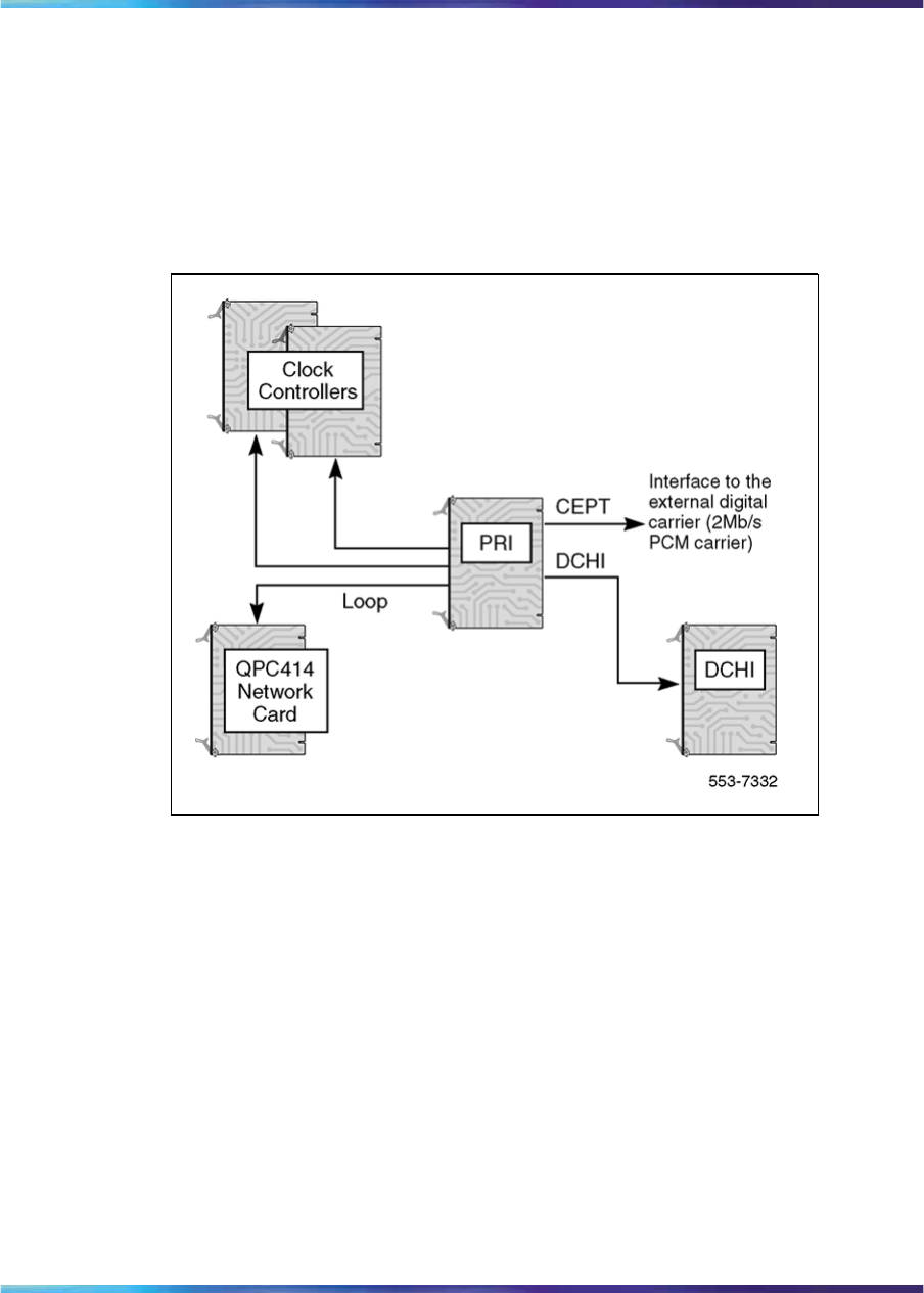
See Figure 1 "PRI hardware (shown without downloadable PRI and DCH
cards)" (page 18) for a representation of the basic PRI system hardware.
Note: Figure 1 shows a basic configuration, not the dual-port NT5D12
DTI/PRI card, nor the associated dual-port NTBK51AA Downloadable
D-Channel daughterboard.
Figure 1
PRI hardware (shown without downloadable PRI and DCH cards)
ISDN Signaling Link (ISL) hardware
The following hardware is required for ISDN Signaling Link (ISL) capability
and applications.
Equipment required for shared mode capability:
•NT6D11(AB/AE/AF) D-Channel (DCH) card (for 2.0 Mb PRI)
•QPC757 D-channel (DCH) for (1.5 Mb PRI)
•NT6D80 Multipurpose Serial Data Link (MSDL) card
•NTBK51 Downloadable D-Channel Daughterboard (DDCH), the NT5D97
dual-port DTI2/PRI2 card, or the NT5D12 dual-port 1.5 Mb DTI/PRI card
•NT8D72 (AB/BA) PRI2 card
•NT5D97 dual-port DTI2/PRI2 card
•QPC720 1.5 Mb PRI card
Nortel Communication Server 1000
ISDN Primary Rate Interface Installation and Commissioning
NN43001-301 02.03 Standard
Release 5.5 7 December 2007
Copyright © 2003-2007, Nortel Networks
.

ISDN Signaling Link (ISL) hardware 19
•NT5D12 dual-port 1.5 DTI/PRI card
•QPC775 Clock Controller or NTRB53
Equipment required for dedicated mode using leased lines:
•NT6D11(AB/AE/AF) D-Channel (DCH) card (for 2.0 Mb PRI)
•QPC757 D-channel (DCH) for (1.5 Mb PRI)
•NT6D80 Multipurpose Serial Data Link (MSDL) card
•NTBK51 Downloadable D-Channel Daughterboard (DDCH), used as
an option to the NT6D80 MSDL
•modem set in synchronous mode
Equipment required for dedicated mode using a dialup modem:
•NT6D11(AB/AE/AF) D-Channel (DCH) card (for 2.0 Mb PRI)
•QPC757 D-channel (DCH) for (1.5 Mb PRI)
•NT6D80 Multipurpose Serial Data Link (MSDL) card
•NTBK51 Downloadable D-Channel Daughterboard (DDCH), used as
an option to the NT6D80 MSDL
•modem with autodial capability
Note: This configuration is the least reliable due to lockup problems
inherent in Smart Modems from power spikes and noisy lines. To
increase the reliability on this configuration, use a constant power
source when powering the modems. Also, verify that TIE lines meet data
grade specifications. Nortel takes no responsibility for ISL D-Channel
outages due to modem lockup.
•500 set line card
•QPC71 2W TIE, or QPC237 4W TIE E&M
Equipment required for dedicated mode using a DTI/DTI2 trunk:
•NT6D11(AB/AE/AF) D-Channel (DCH) card (for 2.0 Mb PRI)
•QPC757 D-channel (DCH) for (1.5 Mb PRI)
•NT6D80 Multipurpose Serial Data Link (MSDL) card
•NTBK51 Downloadable D-Channel Daughterboard (DDCH), used as
an option to the NT6D80 MSDL
•NT5D97 dual-port DTI2/PRI2 card
•QPC472 1.5 Mb DTI card or NT5D12 dual-port 1.5 DTI/PRI card
Nortel Communication Server 1000
ISDN Primary Rate Interface Installation and Commissioning
NN43001-301 02.03 Standard
Release 5.5 7 December 2007
Copyright © 2003-2007, Nortel Networks
.

20 ISDN Primary Rate Interface equipment overview
•QMT8 Asynchronous Data Module (ADM), QMT11 Asynchronous/Syn-
chronous Interface Module (ASIM) or QMT21 High Speed Data Module
(HSDM)
•Data line card
64 Kbit/s Clear Data Hardware
The QMT21 High Speed Data Module (HSDM) is required in the clear-data
pathway to support the 64Kbit/s clear-data function. One module is required
at each system end of any connection.
D-Channel Handler description
This section provides descriptions of the D-Channel (DCH) cards, the MSDL
card, and the Downloadable D-Channel Daughterboard.
NT6D11 DCH
Power requirements
The power requirements for the NT6D11AB/11AE/AF DCH are:
•+5 volts at 3 amperes
•+12 volts at 75 milliamperes
•-12 volts at 75 milliamperes
DCH/PRI interface
The NT6D11AB/AE/AF DCHs connect to the PRI2 cards by means of a
special RS422 cable, the QCAD328A, which is a special RS422 cable; refer
to "QCAD328" (page 300) of the Cabling chapter for more details.
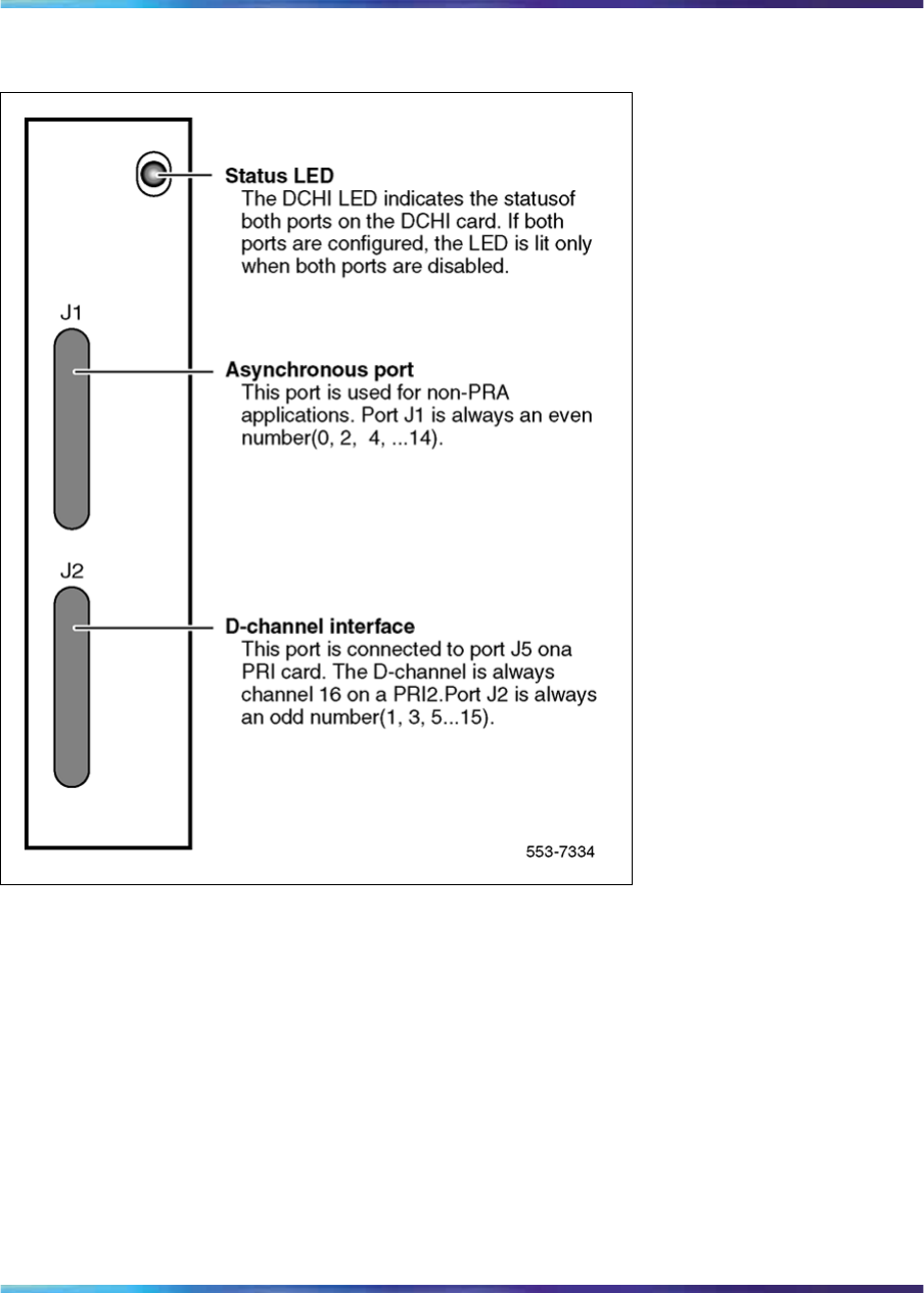
DCH faceplate
NT6D11AB/AE/AF DCHs have one Light Emitting Diode (LED), to indicate
an active or inactive state, and two external connectors:
•Port J1 is a standard asynchronous port providing an interface for
non-PRI applications.
Note: This connection will not support an Add-on Data Module (ADM)
terminal.
•Port J2 is the D-Channel Interface port.
Figure 2 "NT6D11 DCH faceplate layout" (page 21) shows the faceplate
layout.
Nortel Communication Server 1000
ISDN Primary Rate Interface Installation and Commissioning
NN43001-301 02.03 Standard
Release 5.5 7 December 2007
Copyright © 2003-2007, Nortel Networks
.
QPC757 DCH 21
Figure 2
NT6D11 DCH faceplate layout
QPC757 DCH
Power requirements
The power requirements for the QPC757 DCH are:
•+5 volts at 3 amperes
•+12 volts at 50 milliamperes
•–12 volts at 50 milliamperes
DCH/PRI interface
The QPC757 DCH connects to the QPC720 PRI via a RS-422 cable. The
following signals are transmitted across the interface:
•RCV DATA
Nortel Communication Server 1000
ISDN Primary Rate Interface Installation and Commissioning
NN43001-301 02.03 Standard
Release 5.5 7 December 2007
Copyright © 2003-2007, Nortel Networks
.

22 ISDN Primary Rate Interface equipment overview
•RCV CLOCK
•XMIT CLOCK
•XMIT READY
•PRI READY
•DCH READY
PRI READY and DCH READY are handshake signals.
QPC757 faceplate
The QPC757 DCH, as shown in Figure 3 "QPC757 DCH faceplate layout"
(page 23) has one LED to indicate an active or inactive state and two
external connectors as follows:
•Port J1 is a standard asynchronous port in LD 48
Note: This connection does not support an Add-on Data Module (ADM)
terminal.
•Port J2 is the D-Channel Interface port.
Note: A QPC757 vintage C is required if the ISL Revert to Conventional
Signaling feature is configured. The QPC757 vintage D is recommended
for combination ISL/PRI networks using NACD or Network Message
Services and ISL networks using modems.
Nortel Communication Server 1000
ISDN Primary Rate Interface Installation and Commissioning
NN43001-301 02.03 Standard
Release 5.5 7 December 2007
Copyright © 2003-2007, Nortel Networks
.
NT6D80 MSDL 23
Figure 3
QPC757 DCH faceplate layout
NT6D80 MSDL
The NT6D80 MSDL card can be used in conjunction with, or independent
of, the QPC757, or NT6D11AB/AE/AF DCH.
Power requirements
The NT6D80 MSDL power requirements are:
Voltage
(VAC) Current
(Amps) Power
(Watts) Heat
(BTUs)
+5 3.20 16.00 55.36
+12 0.10 1.20 4.15
-12 0.10 1.20 4.15
Nortel Communication Server 1000
ISDN Primary Rate Interface Installation and Commissioning
NN43001-301 02.03 Standard
Release 5.5 7 December 2007
Copyright © 2003-2007, Nortel Networks
.
24 ISDN Primary Rate Interface equipment overview
MSDL/PRI interface
MSDL can connect to PRI trunks through RS-422 or RS-232 interfaces.
The interfaces are switch configured.
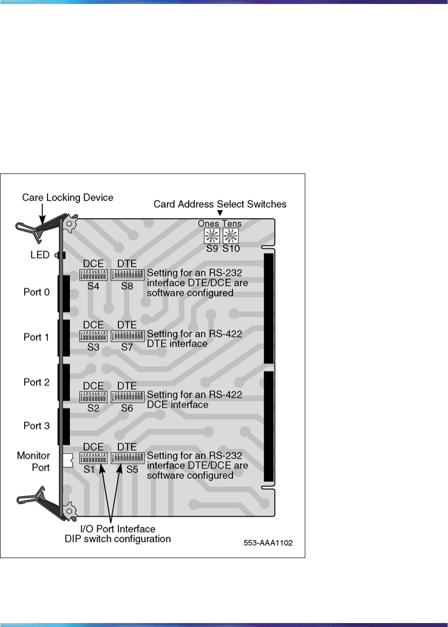
MSDL faceplate
The NT6D80 MSDL has one LED to indicate an active or inactive state and
four external connectors. Each port can be RS-422 or RS-232 connectors,
with either DCE or DTE interfaces. Refer to Figure 4 "NT6D80 MSDL
faceplate layout" (page 24).
Figure 4
NT6D80 MSDL faceplate layout
Nortel Communication Server 1000
ISDN Primary Rate Interface Installation and Commissioning
NN43001-301 02.03 Standard
Release 5.5 7 December 2007
Copyright © 2003-2007, Nortel Networks
.

NT8D72 PRI2 25
NTBK51 Downloadable D-Channel Daughterboard
The NTBK51 is a two port Downloadable D-Channel Daughterboard (DDCH)
that has been introduced as an option to the NT6D80 MSDL, the NT5D97
dual-port DTI2/PRI2 card, or the NT5D12 dual-port 1.5 Mb DTI/PRI card.
The NTBK51 supports all the features of the existing 4 port MSDL
(NT6D80), and eliminates the need for an external DCH card and associated
cables for MSDL applications. The NTBK51 can support a maximum of 32
(16*2) MSDL type D-Channels per system, unlike the MSDL which can
support a maximum of 64.
Note 1: Only one version, the NTBK51AA, can be used with the
NT5D97, or the NT5D12. The NTBK51BA version has only 30+30 pin
connectors (instead of 40+30 pins in the AA version). The missing 10
pins in the BA version prohibits the use of port 0 on the NT5D97, or
NT5D12 card.
Note 2: The software allocation for NTBK51AA DDCH is similar to
the MSDL. It is both physical and logical, and supports D-Channel
functionality only.
Note 3: Port 0 has to be an even loop on the DDP2, and Port 1 has to
be an odd loop. Port 2 and Port 3 should not be configured.
The connection between the dual-port cards and the DDCH daughterboard
is made using two headers: one 30 pin and one 40 pin connector.
Standard PRI cards
This section provides a description of the standard ISDN PRI cards, namely
the NT8D72 (AB/BA) PRI2 card, and the QPC720 1.5 Mb PRI card.
NT8D72 PRI2
Power requirements
The NT8D72AB and NT8D72BA PRI use power and ground connections
from the backplane. Power requirements are:
+5 volts at 4 amperes
+12 volts at 50 milliamperes
-12 volts at 50 milliamperes
NT8D72 faceplate
The NT8D72 contains five LEDs and six external connectors. Figure 5
"NT8D72 PRI faceplate layout" (page 26) shows the faceplate layout.
Nortel Communication Server 1000
ISDN Primary Rate Interface Installation and Commissioning
NN43001-301 02.03 Standard
Release 5.5 7 December 2007
Copyright © 2003-2007, Nortel Networks
.

26 ISDN Primary Rate Interface equipment overview
Figure 5
NT8D72 PRI faceplate layout
Table 2 "NT8D72 PRI External connectors" (page 26) gives information
about the external connectors located on the NT8D72 PRI2 faceplate.
Table 2
NT8D72 PRI External connectors
Faceplate Destination Type Description
J1 9-pin female, D-connector Reference Clock 0 interface
J2 9-pin female, D-connector Reference Clock 1 interface
J3 36-pin connector Loop interface
J4 15-pin male, D-connector External digital trunk
J5 15-pin male, D-connector D-Channel interface
J6 15-pin female, D-connector Echo Canceller/RS-232 interface
Nortel Communication Server 1000
ISDN Primary Rate Interface Installation and Commissioning
NN43001-301 02.03 Standard
Release 5.5 7 December 2007
Copyright © 2003-2007, Nortel Networks
.

NT8D72 PRI2 27
Faceplate Destination Type Description
RCV MON Miniature bantam jack Monitor DSI from network
XMT MON Miniature bantam jack Monitor DSI from PRI
Cable requirements
Table 3 "NT8D72AB and NT8D72BA PRI: Cables and cable lengths" (page
27) lists the types of cable used and the lengths required for internal and
external NT8D72 PRI2 connections.
Note: No additional cabling is required for nB+D configurations. Multiple
PRIs and the D-Channel are associated at the PRI prompt in LD 17.
Table 3
NT8D72AB and NT8D72BA PRI: Cables and cable lengths
Cable Type From To Maximum length
(meters)
NT8D79AA PRI card Clock controller (CC-0) 2.13
NT8D79AA PRI card Clock controller (CC-1) 2.13
QCAD328A PRI card DCH card 1.8
QCAD328B PRI card DCH card 5.5
QCAD328C PRI card DCH card 10.67
QCAD328D PRI card DCH card 15.24
NTND26AA PRI card MSDL 1.8
NTND26AB PRI card MSDL 5.5
NTND26AC PRI card MSDL 10.67
NTND26AD PRI card MSDL 15.24
NT8D85AB PRI card Network Network Card 15.24
RS-232 PRI card Echo canceller 15.24
NT8D7207 PRI card I/O panel 3.05
NT8D7205 I/O panel crossconnect 15.24
Carrier interface
The NT8D72 PRI2 provides an interface to the 2Mb external digital
line either directly or through an office repeater, echo canceller or line
terminating unit (LTU).
Nortel Communication Server 1000
ISDN Primary Rate Interface Installation and Commissioning
NN43001-301 02.03 Standard
Release 5.5 7 December 2007
Copyright © 2003-2007, Nortel Networks
.

28 ISDN Primary Rate Interface equipment overview
Echo canceller interface
Echo cancellers are required only on satellite transmission circuits. The
echo canceller detects the length of the loop, and then cancels out reflected
transmission. (Callers will not hear echoes of their own voices reflecting
back to them from the far end of the call.)
The echo canceller’s control protocol must conform with that of the Tellabs
Model 251. Both the echo canceller and the PRI circuit card act as Data
Terminal Equipment (DTE).
QMT21 High Speed Data Module
The QMT21 High Speed Data Module supports the 64K Clear Data feature.
(It allows data terminating equipment (DTE) to send and receive 64-Kb/s
clear data.) The QMT21B is required for Large System to Large System
configurations.
QPC720 PRI for 1.5/2.0 Mb gateway
Systems which are being used as a 1.5/2.0 Mb Gateway, one or more
QPC720 (1.5 Mb) Primary Rate Interface circuit cards will also be needed.
Note: Older vintages of the QPC720 PRI cannot be used for Gateway
applications. The 1.5/2.0 Mb Gateway feature requires the use of a
QPC720 circuit card with firmware updated to provide modified PAD
values.
Clock operation for the NT8D72
There are two types of clock operation—tracking mode and free-run mode.
Tracking mode
In tracking mode, the PRI loop supplies an external clock reference to a
clock controller. Two PRI loops can operate in tracking mode, with one
defined as the primary reference source for clock synchronization, the other
defined as the secondary reference source. The secondary reference acts
as a back-up to the primary reference.
As shown in Figure 6 "Clock controller primary and secondary tracking"
(page 29), a system with dual CPUs can have two clock controllers (CC-0
and CC-1). One clock controller acts as a back-up to the other. The clock
controllers should be completely locked to the reference clock.
Nortel Communication Server 1000
ISDN Primary Rate Interface Installation and Commissioning
NN43001-301 02.03 Standard
Release 5.5 7 December 2007
Copyright © 2003-2007, Nortel Networks
.

NT8D72 PRI2 29
Figure 6
Clock controller primary and secondary tracking
Free run (non-tracking) mode
The clock synchronization of the system can operate in free-run mode if:
•no loop is defined as the primary or secondary clock reference,
•the primary and secondary references are disabled, or
•the primary and secondary references are in local alarm
Reference clock errors
The system software checks at intervals of 1 to 15 minutes to see if a clock
controller or reference-clock error has occurred. (The interval of this check
can be configured in LD 73.)
In tracking mode, at any one time, there is one active clock controller which
is tracking on one reference clock. If a clock-controller error is detected, the
system switches to the back-up clock controller, without affecting which
reference clock is being tracked.
Nortel Communication Server 1000
ISDN Primary Rate Interface Installation and Commissioning
NN43001-301 02.03 Standard
Release 5.5 7 December 2007
Copyright © 2003-2007, Nortel Networks
.

30 ISDN Primary Rate Interface equipment overview
A reference-clock error occurs when there is a problem with the clock driver
or with the reference clock at the far end. If the clock controller detects a
reference-clock error, the reference clocks are switched.
Automatic clock recovery
A command for automatic clock recovery can be selected in LD 60 with
the command EREF.
A PRI loop is disabled when it enters a local-alarm condition. If the local
alarm is cleared, the loop is enabled automatically. When the loop is
enabled, clock tracking is restored in the following conditions:
1. If the loop is assigned as the primary reference clock but the clock
controller is tracking on the secondary reference or in free-run mode, it
is restored to tracking on primary.
2. If the loop is assigned as the secondary reference clock but the clock
controller is in free-run mode, it is restored to tracking on secondary.
If the clock check indicates the switch is in free-run mode:
1. Tracking is restored to the primary reference clock if defined.
2. If the primary reference is disabled or in local alarm, tracking is restored
to the secondary reference clock if defined.
Note: If the switch is put into free-run mode by the craftsperson, it will
resume tracking on a reference clock unless the clock-switching option
has been disabled (LD 60, command MREF), or the reference clock has
been "undefined" in the database.
Automatic clock switching
If the EREF command is selected in LD 60, tracking on the primary or
secondary reference clock is automatically switched in the following manner:
1. If software is unable to track on the assigned primary reference clock, it
switches to the secondary reference clock and sends appropriate DTC
maintenance messages.
2. If software is unable to track on the assigned secondary reference clock,
it switches to free run.
QPC720 PRI The QPC720 PRI card is required for PRI operation in all machine types.
Power requirements
The QPC720 PRI uses power and ground from the backplane. This card
does not require an intelligent bus. Power requirements are:
•+5 volts at 6 amperes
Nortel Communication Server 1000
ISDN Primary Rate Interface Installation and Commissioning
NN43001-301 02.03 Standard
Release 5.5 7 December 2007
Copyright © 2003-2007, Nortel Networks
.

QPC720 PRI 31
•+12 volts at 50 milliamperes
•-12 volts at 50 milliamperes
QPC720 faceplate
QPC720 PRI contains five LEDs and six external connectors. Figure 7
"QPC720 PRI faceplate layout" (page 31) shows the QPC720 PRI faceplate
layout. Table 4 "QPC720 PRI external connectors" (page 31) gives
information about the external connectors located on the QPC720 PRI
faceplate.
Figure 7
QPC720 PRI faceplate layout
Table 4
QPC720 PRI external connectors
Faceplate destination Type
J1 9-pin female, D-connector
Nortel Communication Server 1000
ISDN Primary Rate Interface Installation and Commissioning
NN43001-301 02.03 Standard
Release 5.5 7 December 2007
Copyright © 2003-2007, Nortel Networks
.

32 ISDN Primary Rate Interface equipment overview
Faceplate destination Type
J2 9-pin female, D-connector
J3 36-pin connector
J4 15-pin male, D-connector
J5 15-pin male, D-connector
J6 15-pin female, D-connector
RCV MON Miniature bantam jack
XMT MON Miniature bantam jack
QPC720 Cable requirements
Table 5 "QPC720 PRI cables and cable lengths" (page 33) lists the types of
cable used and the lengths required for external QPC720 PRI connections.
Note: No additional cabling is required for nB+D configurations. Multiple
PRIs and the D-channel are associated through software in LD 17,
prompt PRI.
Carrier interface
The QPC720 PRI provides an interface to the DS-1 Channel either directly,
through an office repeater, or through an Echo Canceller.
The T1 Channel Service Units listed below are compatible with the QPC720
PRI card and the 64K Clear Data feature as well as with PRI connection
parameters such as the Superframe format, the Extended superframe
format, and the B7 and B8ZS Alternate Mark Inversion (AMI) line coding.
•Digital Link 551A
•Digital Link 551C
•Digital Link 551E
•Tellabs Model 441
•Verilink Model 551V ST
In the U.S.A., FCC Part 68 regulations require Network Channel Terminating
Equipment (for example, the NT QRY551 Channel Service Unit) installed
at of the point of connection between a system and a registered common
carrier trunk.
Echo Canceller interface
Echo Cancellers are required only with satellite transmission. The Echo
Canceller detects the length of the loop, then cancels the reflected
transmission (callers do not hear their own voices echoed).
Nortel Communication Server 1000
ISDN Primary Rate Interface Installation and Commissioning
NN43001-301 02.03 Standard
Release 5.5 7 December 2007
Copyright © 2003-2007, Nortel Networks
.

QPC720 PRI 33
The QPC720 PRI provides both a T1 line interface and a control interface to
link to a signal format compatible with EIA standard RS-232-C. Both the PRI
and the Echo Canceller act as Data Terminal Equipment (DTE). The Echo
Canceller’s control protocol must conform to that of the Tellabs Model 251.
64 T-link version 2 protocol
The QPC720 card supports the 64 T-link version 2 protocol. The QPC720
together with theQMT21 High Speed Data Module supports the 64K Clear
Data feature. The QPC720 card provides a trunk that ties two switches
together. This trunk allows 64K eClear Data to pass from the system to an
outside network. The QMT21 module allows Data Terminal Equipment
(DTE) to send and receive 64K Clear Data. See Meridian Link ISDN/AP
General Guide (553-2901-100) for more information about the 64K Clear
Data feature.
Table 5
QPC720 PRI cables and cable lengths
Cable type From To Maximum
length (feet)
Maximum
length
(meters)
QCAD130 QPC720 QPC471/QPC775 (CC-0) 72.13
QCAD130 QPC720 QPC471/QPC775 (CC-1) 72.13
QCAD328A QPC720 QPC757 DCHI 6 1.8
QCAD328B QPC720 QPC757 DCHI 18 5.5
QCAD328C QPC720 QPC757 DCHI 35 10.67
QCAD328D QPC720 QPC757 DCHI 50 15.24
QCAD124 QPC720 QPC414 Network 50 15.24
QCAD128 QPC720 Bulkhead I/O panel 25 7.62
RS-232 QPC720 Echo Canceller 50 15.24
NTND26AA QPC720 NT6D80 MSDL 6 1.8
NTND26AB QPC720 NT6D80 MSDL 18 5.5
NTND26AC QPC720 NT6D80 MSDL 35 10.67
NTND26AD QPC720 NT6D80 MSDL 50 15.24
NTND98 QPC720 Input/output panel 6 1.8
22AWG ABAM Echo Canceller DSX-1 655 199.64
Note: The QPC775 Clock Controller is not available in the U.S.A. There
can be no mixing of QPC775 and QPC471 in one system.
Nortel Communication Server 1000
ISDN Primary Rate Interface Installation and Commissioning
NN43001-301 02.03 Standard
Release 5.5 7 December 2007
Copyright © 2003-2007, Nortel Networks
.
34 ISDN Primary Rate Interface equipment overview
Disk drive hardware
The following hardware is required for Large System upgrades:
•3.5-inch disk drive unit
•disk drive controller for above
•cable for above
NT5D97 Dual-port DTI2/PRI2 card
The NT5D97 is a dual-port 2.0 Mb DTI2/PRI2 card (the DDP2 firmware
functions in DTI2 or PRI2 mode, depending on DIP switch settings) that
integrates the functionality of two NT8D72BA PRI2 cards, and one QPC414
ENET card into a single CE card. The NT5D97 occupies a single slot in
the Network shelf and provides two DTI2/PRI2 network connections: an
interface to an external D-Channel Handler (the NT6D11AF) or the NT6D80
Multipurpose Serial Data Link card, and an optional plug-on NTBK51AA
Downloadable D-Channel daughterboard (DDCH) with two DCH interface
ports.
The NT5D97 DDP2 card can be mixed in the same machine with PRI2
NT8D72BA cards.
The NT5D97 DDP2 card hardware design uses a B57 ASIC E1/T1 framer.
The carrier specifications comply with the ANSI TI.403 specification. The
NT5D97 provides an interface to the 2.048 Mbps external digital line
either directly or through an office repeater, Network Channel Terminating
Equipment (NCTE), or Line Terminating Unit (LTU).
DANGER
DANGER OF ELECTRIC SHOCK
The NT5D97 DDP2 card is not designed to be connected
directly to the Public Switched Network, or other exposed plant
networks. Such a connection should only be done using an
isolating-type networking terminating device that provides voltage
surge protection, such as a Line Terminating Unit (LTU), Network
Channel Terminating Equipment (NCTE), or Network Termination
1 (NT1), as certified by your local, regional, or national safety
agency and telecommunications authority.
External D-Channel Interface DCH or MSDL
The connection between the DDP2 card and the external DCH or MSDL is
through a 26 pin female D type connector. The data signals conform to the
electrical characteristics of the EIA standard RS-422.
Nortel Communication Server 1000
ISDN Primary Rate Interface Installation and Commissioning
NN43001-301 02.03 Standard
Release 5.5 7 December 2007
Copyright © 2003-2007, Nortel Networks
.

NT5D97 Dual-port DTI2/PRI2 card 35
Two control signals are used to communicate the D-channel link status
to the DCH or MSDL. These are:
•Receiver Ready (RR), originating at the DDP2 card, to indicate to the
DCH or MSDL that the D-channel link is operational.
•Transmitter Ready (TR), originating at the DCH or MSDL, to indicate to
the DDP2 card that the DCH are ready to use the D-channel link.
Table 6 "DCH/MSDL Receiver Ready control signals" (page 35) indicates
how the RR control signal operates with regard to the DDP2 status.
Table 6
DCH/MSDL Receiver Ready control signals
RR State Condition
ON D-Channel data rate selected at 64 Kbps
and
PRI2 loop is enabled
and
PRI2 link is not in OOS or Local Alarm mode state
and
PRI2 link is not transmitting a Remote Alarm pattern
and
PRI2 link is not receiving a Remote Alarm Indication from
a remote facility
OFF All other conditions
NT5D97 faceplate
Figure 8 "NT5D97 faceplate" (page 36) illustrates the faceplate layout for
the NT5D97 DDP card. The faceplate contains an enable/disable switch;
a DDCH status LED; 6 x 2 trunk port status LEDs; and six external
connectors. Table 7 "External connectors and LEDs" (page 36) shows the
name of each connector, its designation with respect to the faceplate and
the name and description of the card it is connected to. Also shown are the
names of the LEDs.
Nortel Communication Server 1000
ISDN Primary Rate Interface Installation and Commissioning
NN43001-301 02.03 Standard
Release 5.5 7 December 2007
Copyright © 2003-2007, Nortel Networks
.
36 ISDN Primary Rate Interface equipment overview
Figure 8
NT5D97 faceplate
Table 7
External connectors and LEDs
Function Faceplate
Designator Type Description
Switch ENB/DIS Plastic, ESD protected Card Enable/disable
switch
Nortel Communication Server 1000
ISDN Primary Rate Interface Installation and Commissioning
NN43001-301 02.03 Standard
Release 5.5 7 December 2007
Copyright © 2003-2007, Nortel Networks
.

NT5D97 Dual-port DTI2/PRI2 card 37
Function Faceplate
Designator Type Description
Unit 0 Clock 0 RJ11 Connector Connects reference
clock 0 to Clock
Controller card 0
Unit 0 Clock 1 RJ11 Connector Connects reference
clock 0 to Clock
Controller card 1
Unit 1 Clock 0 RJ11 Connector Connects reference
clock 1 to Clock
Controller card 0
Unit 1 Clock 1 RJ11 Connector Connects reference
clock 1 to Clock
Controller card 1
J5 TRK 9 Pin
Female D Connector Two external E1 Trunk
0 and Trunk 1
Connectors
J6 DCH 26 Pin
Female D Connector Connects to external
DCH or MSDL
ENET 2 Red LEDs ENET 0 or ENET 1 is
disabled
DIS 2 Red LEDs Trunk 0 or Trunk 1 is
disabled
OOS 2 Yellow LEDs Trunk is out of service
NEA 2 Yellow LEDs Local (Near End) Alarm
FEA 2 Yellow LEDs Far End Alarm
LBK 2 Yellow LEDs Loop Back test being
performed on Trunk 0
or Trunk 1
LEDs
DCH Bicolor Red/Green LED NTBK51AA status
The following is a brief description of each element on the faceplate.
Enable/Disable Switch
This switch is used to disable the card prior to insertion or removal from
the network shelf. While this switch is in disable position, the card will not
respond to the system CPU.
ENET LEDs
Two red LEDs indicate if the "ENET0" and "ENET1" portions of the card are
disabled. These LEDs are lit in the following cases:
•When the enable/disable switch is in disabled state (lit by hardware).
•After power-up, before the card is enabled.
Nortel Communication Server 1000
ISDN Primary Rate Interface Installation and Commissioning
NN43001-301 02.03 Standard
Release 5.5 7 December 2007
Copyright © 2003-2007, Nortel Networks
.

38 ISDN Primary Rate Interface equipment overview
•When the ENET port on the card is disabled by software.
Trunk Disable (DIS) LEDs
Two red LEDs indicate if the "trunk port 0" or "trunk port 1" portions of the
card are disabled. These LEDs are lit in the following cases:
•upon reception of the "disable loop" message from the software
•after power-up
OOS LEDs
Two yellow LEDs indicate if the "trunk port 0" and "trunk port 1" portions of
the card are out-of-service.
NEA LEDs
Two yellow LEDs indicate if the near end detects absence of incoming signal
or loss of synchronization in "trunk port 0" or "trunk port 1" respectively.
The Near End Alarm causes a Far End Alarm signal to be transmitted to
the far end.
FEA LEDs
Two yellow LEDs indicate if a Far End Alarm has been reported by the far
end (usually in response to a Near End Alarm condition at the far end)
on "trunk port 0" or "trunk port 1".
LBK LEDs
Two yellow LEDs indicate if a remote loopback test is being performed on
trunk port 0 or trunk port 1. The loopback indication is active when the
digital trunk is in remote loopback mode. Normal call processing is inhibited
during the remote loopback test.
DCH LED
When the dual colored LED is red, it indicates the onboard DDCH is present
but disabled. When the dual colored LED is green, it indicates the onboard
DDCH is present and enabled. If a DDCH is not configured on the DDP2
card, this lamp is not lit.
Unit 0 Clk Connectors
Two RJ11 connectors for connecting:
•Digital trunk unit 0 recovered clock to primary or secondary reference
source on clock controller card 0.
•Digital trunk unit 0 recovered clock to primary or secondary reference
source on clock controller card 1.
Nortel Communication Server 1000
ISDN Primary Rate Interface Installation and Commissioning
NN43001-301 02.03 Standard
Release 5.5 7 December 2007
Copyright © 2003-2007, Nortel Networks
.

NT5D97 Dual-port DTI2/PRI2 card 39
Unit 1 Clk Connectors
Two RJ11 connectors for connecting:
•Digital trunk unit 1 recovered clock to primary or secondary reference
source on clock controller card 0.
•Digital trunk unit 1 recovered clock to primary or secondary reference
source on clock controller card 1.
Connector J5 (TRK)
A 9 pin D-Type connector used to connect:
•Digital trunk unit 0 receive and transmit Tip / Ring pairs
•Digital trunk unit 1 receive and transmit Tip / Ring pairs
Connector J6 (DCH)
A 26-pin D-type connector is used to connect the DDP2 card to the external
MSDL or D-channel handler.
System capacity and performance
Physical capacity
Each NT5D97 DDP2 card occupies one slot on the network shelf. Each card
supports two digital trunk circuits and two network loops. The total number
of DDP2 cards per system is limited by the number of network loops,
physical capacity of the shelf, number of DTI2/PRI2 interfaces allowed by
the software and the range of DCH addresses.
D-Channel capacity
The software configuration for the NTBK51AA DDCH is similar to the MSDL
and only supports D-channel functionality.
The system has a total capacity of 16 addresses (Device Addresses or
DNUM) that can be reserved for DCH card, MSDL card or DDCH card. One
exception is DNUM 0 which is commonly assigned to the TTY terminal.
No two different D-Channel providers can share the same DNUM. Hence,
the combined maximum number of DCH, MSDL and DDCH cards in the
system is 16.
The DCH has one D-Channel unit, the DDCH has two D-Channel units,
and the MSDL has a maximum of four units. Therefore, the total number
of D-Channel is derived by the following formula:
Total_Num_DCH-Units = Num_DCHx1 + Num_DDCHx2 + Num_MSDLx4
Therefore, Total_Num_DCH-Units in any given system is between 0-63.
Nortel Communication Server 1000
ISDN Primary Rate Interface Installation and Commissioning
NN43001-301 02.03 Standard
Release 5.5 7 December 2007
Copyright © 2003-2007, Nortel Networks
.
40 ISDN Primary Rate Interface equipment overview
CPU capacity
Using a NT5D97 DDP2 card instead of DTI2/PRI2 cards does not increase
the load on the system CPU. The DDP2 replaces an ENET card and two
DTI2/PRI2 cards. Emulating the ENET card and the overall CPU capacity is
not impacted by using a DDP2 card instead of a DTI2/PRI2 card.
Power requirements
Table 8 "NT5D97 DDP2 power requirements" (page 40) lists the power
requirements for the NT5D97 DDP2 card.
Table 8
NT5D97 DDP2 power requirements
Voltage Source Current
DDP2
(without
NTBK51AA)
DDP2
(with
NTBK51AA)
+5V Backplane 3A 3.8A
+12V Backplane 25mA 75mA
-12V Backplane 25mA 75mA
Total Power (Maximum) 15.6W 20.8W
Testability and diagnostics
The DDP2 card supports testing and maintenance functions through the
following procedures:
•Self test upon power up or reset
•Signalling test performed in the LD 30
•Loopback tests, self tests, and continuity tests performed by LD 60
and LD 45
•The D-Channel (DCH, MSDL, DDCH) maintenance is supported by
LD 96.
Note: The MSDL selftest is not applicable to the NTBK51AA D-Channel
daughterboard.
Cable requirements
This section lists the types of cable used and the lengths required for
internal and external NT5D97 DDP2 connections.
Note: No additional cabling is required for nB+D configurations. Multiple
DDP2 cards and the D-channel are associated through software in
LD 17.
Nortel Communication Server 1000
ISDN Primary Rate Interface Installation and Commissioning
NN43001-301 02.03 Standard
Release 5.5 7 December 2007
Copyright © 2003-2007, Nortel Networks
.

NT5D97 Dual-port DTI2/PRI2 card 41
DDP2 cable assemblies include:
•E1 carrier cables
— NTCK45AA (A0407956)
— NT8D7217 (A0617192)
— NTCK78AA (A0618294)
— NTCK79AA (A0618296)
•DDP2 to QPC471/QPC775 Clock Controller Cables
— NTCG03AA
— NTCG03AB
— NTCG03AC
— NTCG03AD
•DDP2 to DCH cables
— NTCK46AA
— NTCK46AB
— NTCK46AC
— NTCK46AD
•DDP2 to MSDL cables
— NTCK80AA
— NTCK80AB
— NTCK80AC
— NTCK80AD
A description of each type of DDP2 cable follows.
E1 carrier cables
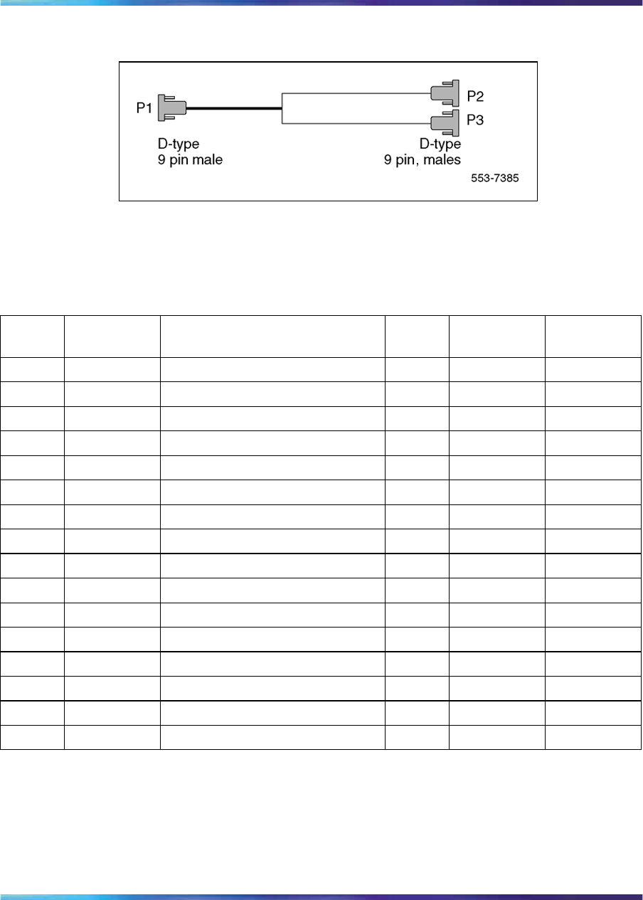
NTCK45AA (A0407956) The NTCK45AA (8 ft.) is an 120W cable for
systems equipped with an I/O filter panel, connecting the TRK port (P1,
D-type 9 pin male) on the DDP2 faceplate to the I/O filter (P2, P3 D-type 9
pin males).
Nortel Communication Server 1000
ISDN Primary Rate Interface Installation and Commissioning
NN43001-301 02.03 Standard
Release 5.5 7 December 2007
Copyright © 2003-2007, Nortel Networks
.
42 ISDN Primary Rate Interface equipment overview
Figure 9
NTCK45AA
Table 9 "NTCK45AA cable pins" (page 42) lists the pin attributes for the
NTCK45AA cable.
Table 9
NTCK45AA cable pins
Cable Name Description Color DDP2
pins I/O Panel
pins
0T-PRI0TX Trunk 0 Transmit Tip Black P1-1 P2-6
0R-PRI0TX Trunk 0 Transmit Ring Red P2-2 P2-7
0T-PRI0RX Trunk 0 Receive Tip Black P1-3 P2-2
0R-PRI0RX Trunk 0 Receive Ring White P1-4 P2-3
0GND Shield Wire Bare N/C Case P2
0GND Shield Wire Bare N/C Case P2
0Standard Wire (3") Bare Case P2 P2-5
0Standard Wire (3") Bare Case P2 P2-9
1T-PRI1TX Trunk 1 Transmit Tip Black P1-5 P3-6
1R-PRI1TX Trunk 1 Transmit Ring Red P1-6 P3-7
1T-PRI1RX Trunk 1 Receive Tip Black P1-7 P3-2
1R-PRI1RX Trunk 1 Receive Ring White P1-8 P3-3
1GND Shield Wire Bare N/C Case P3
1GND Shield Wire Bare N/C Case P3
1Standard Wire (3") Bare Case P3 P3-5
1Standard Wire (3") Bare Case P3 P3-9
NT8D7217 (A0617192) The NT8D7217 (50 ft.) is a 120W cable for
systems equipped with an I/O filter panel, connecting the 9 pin I/O filter
connector to the 9 pin NCTE connector.
Nortel Communication Server 1000
ISDN Primary Rate Interface Installation and Commissioning
NN43001-301 02.03 Standard
Release 5.5 7 December 2007
Copyright © 2003-2007, Nortel Networks
.
NT5D97 Dual-port DTI2/PRI2 card 43
Figure 10
NT8D7217
Table 10 "NT8D7217 cable pins" (page 43) which follows lists the pin
attributes for the NT8D7217 cable.
Table 10
NT8D7217 cable pins
Cable Name Description Color DDP2
pins I/O Panel
pins
0T-PRI0TX Trunk 0 Transmit Tip Black P1-6 P2-6
0R-PRI0TX Trunk 0 Transmit Ring White P1-7 P2-7
0T-PRI0RX Trunk 0 Receive Tip Black P1-2 P2-2
0R-PRI0RX Trunk 0 Receive Ring Red P1-3 P2-3
0GND Shield Wire Bare P1-5 N/C
0GND Shield Wire Bare P1-9 N/C
1T-PRI1TX Trunk 1 Transmit Tip Black P1-6 P2-6
1R-PRI1TX Trunk 1 Transmit Ring White P1-7 P2-7
1T-PRI1RX Trunk 1 Receive Tip Black P1-2 P2-2
1R-PRI1RX Trunk 1 Receive Ring Red P1-3 P2-3
1GND Shield Wire Bare P1-5 N/C
1GND Shield Wire Bare P1-9 N/C
NTCK78AA (A0618294) The NTCK78AA (50 ft.) is a 120W cable for
connecting the TRK port on the DDP2 faceplate (P1, D-type 9 pin male)
to the Main Distribution Frame (MDF) (P2, P3 D-type 15-pin males). The
NTCK78AA is used for systems not equipped with an I/O filter panel.
Nortel Communication Server 1000
ISDN Primary Rate Interface Installation and Commissioning
NN43001-301 02.03 Standard
Release 5.5 7 December 2007
Copyright © 2003-2007, Nortel Networks
.
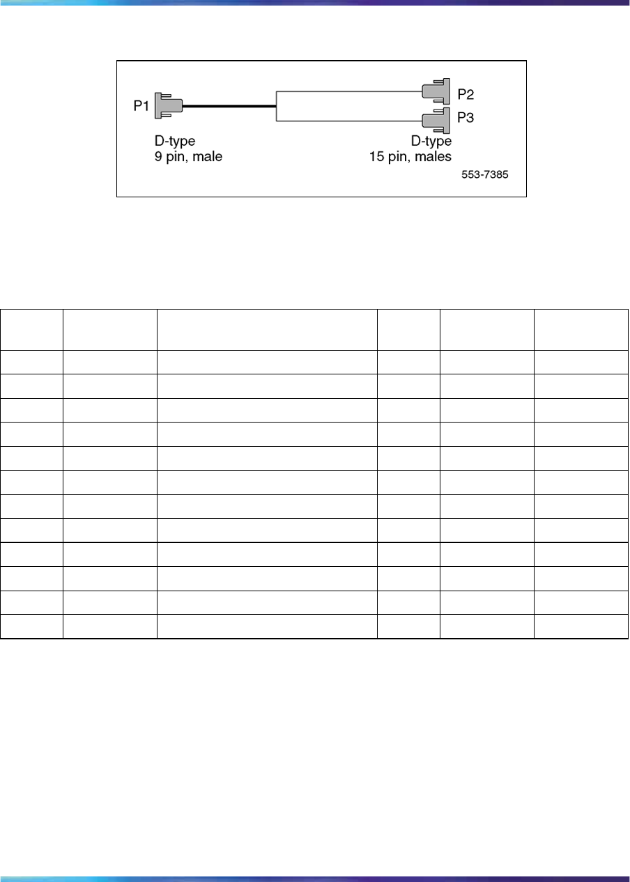
44 ISDN Primary Rate Interface equipment overview
Figure 11
NTCK78AA
Table 11 "NTCK78AA cable pins" (page 44) lists the pin attributes for the
NTCK78AA cable.
Table 11
NTCK78AA cable pins
Cable Name Description Color DDP2
pins NCTE
pins
0T-PRI0TX Trunk 0 Transmit Tip Black P1-1 P2-1
0R-PRI0TX Trunk 0 Transmit Ring Red P1-2 P2-9
0T-PRI0RX Trunk 0 Receive Tip Black P1-3 P2-3
0R-PRI0RX Trunk 0 Receive Ring White P1-4 P2-11
0GND Shield Wire Bare P1 Case P2-2
0GND Shield Wire Bare P1 Case P2-4
1T-PRI1TX Trunk 1 Transmit Tip Black P1-5 P3-1
1R-PRI1TX Trunk 1 Transmit Ring Red P1-6 P3-9
1T-PRI1RX Trunk 1 Receive Tip Black P1-7 P3-3
1R-PRI1RX Trunk 1 Receive Ring White P1-8 P3-11
1GND Shield Wire Bare P1 Case P3-2
1GND Shield Wire Bare P1 Case P3-4
NTCK79AA (A0618296) The NTCK79AA (40 ft) is a 75W coaxial cable for
connecting the TRK port on the DDP2 faceplate (P1, D-type 9 pin male) to
the Line Terminating Unit (LTU) (P2, P3, P4, P5 BNC males).
Nortel Communication Server 1000
ISDN Primary Rate Interface Installation and Commissioning
NN43001-301 02.03 Standard
Release 5.5 7 December 2007
Copyright © 2003-2007, Nortel Networks
.

NT5D97 Dual-port DTI2/PRI2 card 45
Figure 12
NTCK79AA
Table 12 "NTCK79AA cable pins" (page 45) lists the pin attributes for the
NTCK79AA cable.
Table 12
NTCK79AA cable pins
Cable Name Description Color DDP2
pins NCTE
pins
0T-PRI0TX Trunk 0 Transmit Tip Red P1-1 P2 inner
conductor
0R-PRI0TX Trunk 0 Transmit Ring Red P1-2 P2 shield
0T-PRI0RX Trunk 0 Receive Tip Green P1-3 P3 inner
conductor
0R-PRI0RX Trunk 0 Receive Ring Green P1-4 P3 shield
1T-PRI1TX Trunk 1 Transmit Tip Red P1-5 P4 inner
conductor
1R-PRI1TX Trunk 1 Transmit Ring Red P1-6 P4 shield
1T-PRI1RX Trunk 1 Transmit Tip Green P1-7 P5 inner
conductor
1R-PRI1RX Trunk 1 Receive Ring Green P1-8 P5 shield
1Outer metalized PVC shield Bare N/C P1 Case
13 stranded wire Bare N/C P1 Case
Reference clock cables
The NTCG03AA (14 ft), NTCG03AB (2.8 ft), NTCG03AC (4.0 ft), or
NTCG03AD (7 ft), is a DDP2 card to Clock Controller cable, connecting
each of the CLK0 or CLK1 ports on the DDP2 faceplate to the primary or
secondary source ports on Clock Controller card 0 or 1.
Nortel Communication Server 1000
ISDN Primary Rate Interface Installation and Commissioning
NN43001-301 02.03 Standard
Release 5.5 7 December 2007
Copyright © 2003-2007, Nortel Networks
.

46 ISDN Primary Rate Interface equipment overview
Figure 13
NTCG03AA/AB/AC/AD
MSDL/DCH cables
External DCH cable The NTCK46 cable connects the DDP2 card to the
NT6D11AF/NT5K75AA/NT5K35AA D-Channel Handler card. The cable
is available in four different sizes:
•NTCK46AA (6 ft.) - DDP2 to DCH cable
•NTCK46AB (18 ft.) - DDP2 to DCH cable
•NTCK46AC (35 ft.) - DDP2 to DCH cable
•NTCK46AD (50 ft.) - DDP2 to DCH cable
Figure 14
NTCK46AA/AB/AC/AD
External MSDL cable The NTCK80 cable connects the DDP2 card to the
NT6D80 MSDL card. The cable is available in four different sizes:
•NTCK80AA (6 ft) - DDP2 to MSDL cable
•NTCK80AB (18 ft) - DDP2 to MSDL cable
•NTCK80AC (35 ft) - DDP2 to MSDL cable
•NTCK80AD (50 ft) - DDP2 to MSDL cable
Nortel Communication Server 1000
ISDN Primary Rate Interface Installation and Commissioning
NN43001-301 02.03 Standard
Release 5.5 7 December 2007
Copyright © 2003-2007, Nortel Networks
.

NT5D97 Dual-port DTI2/PRI2 card 47
Figure 15
NTCK80AA/AB/AC/AD
Cable diagrams
Figure 16 "DDP2 cable for systems with an I/O panel" (page 48) and
Figure 17 "DDP2 cable for systems without an I/O panel" (page 49) provide
examples of typical cabling configurations for the DDP2.
Figure 16 "DDP2 cable for systems with an I/O panel" (page 48) shows a
typical DDP2 cabling for a system with an I/O panel, with the connection
between the I/O panel and a Network Channel Terminating Equipment
(NCTE).
Figure 17 "DDP2 cable for systems without an I/O panel" (page 49) shows
cabling for a system without an I/O panel. Here, the DDP2 faceplate is
cabled directly to the NCTE.
Note: Since several clock cabling options exist, none has been
represented in the diagrams. Refer to "Clock configurations" (page
52) for a description on each available option.
Nortel Communication Server 1000
ISDN Primary Rate Interface Installation and Commissioning
NN43001-301 02.03 Standard
Release 5.5 7 December 2007
Copyright © 2003-2007, Nortel Networks
.
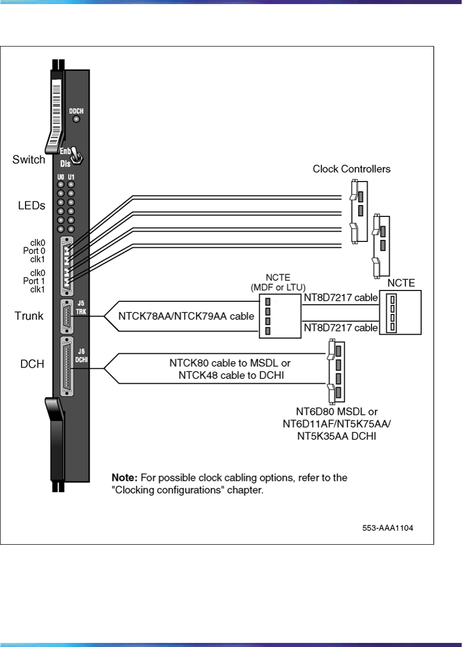
48 ISDN Primary Rate Interface equipment overview
Figure 16
DDP2 cable for systems with an I/O panel
Nortel Communication Server 1000
ISDN Primary Rate Interface Installation and Commissioning
NN43001-301 02.03 Standard
Release 5.5 7 December 2007
Copyright © 2003-2007, Nortel Networks
.
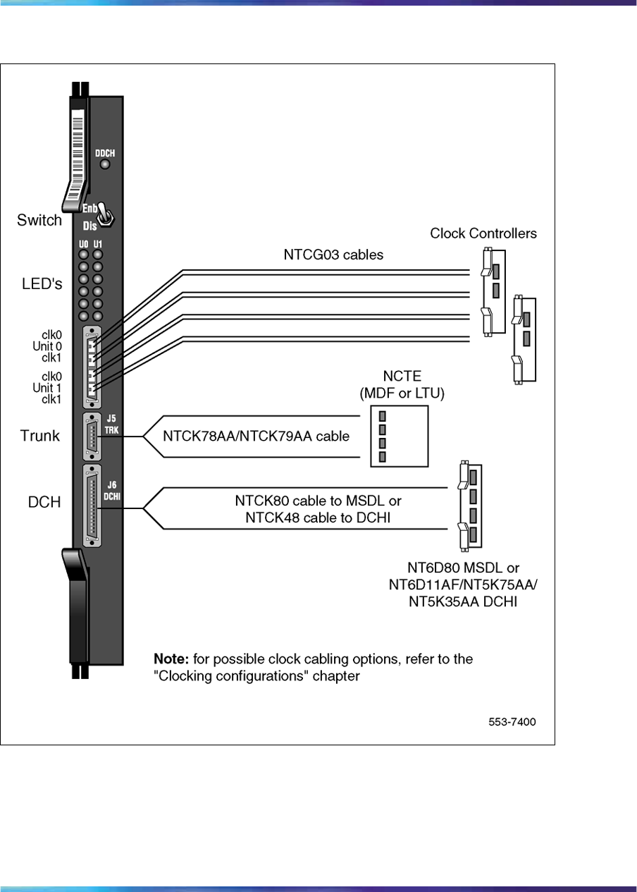
NT5D97 Dual-port DTI2/PRI2 card 49
Figure 17
DDP2 cable for systems without an I/O panel
Clock for the NT5D97
Clock operation
There are two types of clock operation — tracking mode and free-run mode.
Nortel Communication Server 1000
ISDN Primary Rate Interface Installation and Commissioning
NN43001-301 02.03 Standard
Release 5.5 7 December 2007
Copyright © 2003-2007, Nortel Networks
.
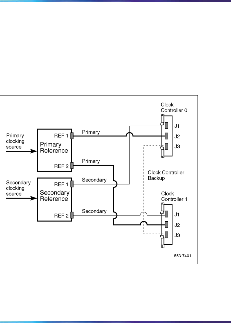
50 ISDN Primary Rate Interface equipment overview
Tracking mode In tracking mode, the DDP2 loop supplies an external
clock reference to a clock controller. Two DDP2 loops can operate in
tracking mode, with one defined as the primary reference source for clock
synchronization, the other defined as the secondary reference source. The
secondary reference acts as a back-up to the primary reference.
As shown in Figure 18 "Clock Controller primary and secondary tracking"
(page 50), a system with dual CPUs can have two clock controllers (CC-0
and CC-1). One clock controller acts as a back-up to the other. The clock
controllers should be completely locked to the reference clock.
Figure 18
Clock Controller primary and secondary tracking
Free run (non-tracking) mode The clock synchronization of the system
can operate in free-run mode if:
•no loop is defined as the primary or secondary clock reference,
•the primary and secondary references are disabled, or
•the primary and secondary references are in local (near end) alarm
Nortel Communication Server 1000
ISDN Primary Rate Interface Installation and Commissioning
NN43001-301 02.03 Standard
Release 5.5 7 December 2007
Copyright © 2003-2007, Nortel Networks
.

NT5D97 Dual-port DTI2/PRI2 card 51
Reference clock errors
The system software checks at intervals of 1 to 15 minutes to see if a clock
controller or reference-clock error has occurred. (The interval of this check
can be configured in LD 73).
In tracking mode, at any one time, there is one active clock controller which
is tracking on one reference clock. If a clock controller error is detected, the
system switches to the back-up clock controller, without affecting which
reference clock is being tracked.
A reference-clock error occurs when there is a problem with the clock driver
or with the reference clock at the far end. If the clock controller detects a
reference-clock error, the reference clocks are switched.
Automatic clock recovery
A command for automatic clock recovery can be selected in LD 60 with
the command EREF.
A DDP2 loop is disabled when it enters a local-alarm condition. If the local
alarm is cleared, the loop is enabled automatically. When the loop is
enabled, clock tracking is restored in the following conditions:
•If the loop is assigned as the primary reference clock but the clock
controller is tracking on the secondary reference or in free-run mode, it
is restored to tracking on primary.
•If the loop is assigned as the secondary reference clock but the clock
controller is in free-run mode, it is restored to tracking on secondary.
•If the clock check indicates the switch is in free-run mode:
— Tracking is restored to the primary reference clock if defined.
— If the primary reference is disabled or in local alarm, tracking is
restored to the secondary reference clock if defined.
Note: If the system is put into free-run mode by the craftsperson,
it resumes tracking on a reference clock unless the clock-switching
option is disabled (LD 60, command MREF), or the reference clock is
"undefined" in the database.
Automatic clock switching
If the EREF command is selected in LD 60, tracking on the primary or
secondary reference clock is automatically switched in the following manner:
•If software is unable to track on the assigned primary reference clock, it
switches to the secondary reference clock and sends appropriate DTC
maintenance messages.
•If software is unable to track on the assigned secondary reference clock,
it switches to free run.
Nortel Communication Server 1000
ISDN Primary Rate Interface Installation and Commissioning
NN43001-301 02.03 Standard
Release 5.5 7 December 2007
Copyright © 2003-2007, Nortel Networks
.

52 ISDN Primary Rate Interface equipment overview
Clock configurations
Clock Controllers can be used in a single or a dual CPU system.
A single CPU system has one Clock Controller card. This card can receive
reference clocks from two sources referred to as the primary and secondary
sources. These two sources can originate from a PRI2, DTI2, etc. PRI2
cards such as the NT8D72BA are capable of supplying two references of
the same clock source. These are known as Ref1 (available at J1) and Ref2
(available at J2) on the NT8D72BA.
The NT5D12 card is capable of supplying two references from each clock
source, i.e., four references in total. NT5D12 can supply Clk0 and Clk1 from
Unit 0 and Clk0 and Clk1 from Unit 1. Either Unit 0 or Unit 1 can originate
primary source, as shown in Figure 19 "Clock Controller - Option 1" (page
54) through Figure 22 "Clock Controller - Option 4" (page 57) on pages
Figure 18 "Clock Controller primary and secondary tracking" (page 50) to
Figure 22 "Clock Controller - Option 4" (page 57).
There is one Clock Controller cable required for the DDP2 card, which
is available in four sizes; this is the NTCG03AA/AB/AC/AD. Refer to
"Reference clock cables" (page 45) for more information.
Table 13 "Clock Controller options - summary" (page 52) summarizes the
clocking options. Table 14 "Clock Controller options - description" (page
53) explains the options in more detail.
Table 13
Clock Controller options - summary
CC Option CPU Type Notes
Option 1 Single Ref from P0 on Clk0
Ref from P1 on Clk0
Option 2 Dual Ref from P0 on Clk0
Ref from P0 on Clk1
Option 3 Dual Ref from P1 on Clk0
Ref from P1 on Clk1
Option 4 Dual Ref from P0 on Clk0
Ref from P0 on Clk1
Ref from P1 on Clk0
Ref from P1 on Clk1
Nortel Communication Server 1000
ISDN Primary Rate Interface Installation and Commissioning
NN43001-301 02.03 Standard
Release 5.5 7 December 2007
Copyright © 2003-2007, Nortel Networks
.

NT5D97 Dual-port DTI2/PRI2 card 53
Table 14
Clock Controller options - description
Clock Option Notes
Option 1 This option provides a single CPU system with 2 clock
sources derived from the 2 ports of the DDP2.
Connector Clk0 provides a clock source from Unit 0.
Connector Clk0 provides a clock source from Unit 1.
Refer to Figure 19 "Clock Controller - Option 1" (page
54).
Option 2 This option provides a Dual CPU system with 2
references of a clock source derived from port 0 of the
DDP2.
Connector Clk0 provides a Ref 1 clock source from
Unit 0.
Connector Clk1 provides a Ref 2 clock source from
Unit 0.
Refer to Figure 20 "Clock Controller - Option 2" (page
55)
Option 3 This option provides a Dual CPU system with 2
references of a clock source derived from port 1 of the
DDP2.
Connector Clk0 provides a Ref 1 clock source from
Unit 1.
Connector Clk1 provides a Ref 2 clock source from
Unit 1.
Refer to Figure 21 "Clock Controller - Option 3" (page
56)
Option 4 This option provides a Dual CPU system with 2
references from each clock source derived from the
DDP2.
Connector Clk0 provides a Ref 1 clock source from
Unit 0.
Nortel Communication Server 1000
ISDN Primary Rate Interface Installation and Commissioning
NN43001-301 02.03 Standard
Release 5.5 7 December 2007
Copyright © 2003-2007, Nortel Networks
.
54 ISDN Primary Rate Interface equipment overview
Clock Option Notes
Connector Clk1 provides a Ref 2 clock source from
Unit 0.
Connector Clk0 provides a Ref 1 clock source from
Unit 1.
Connector Clk1 provides a Ref 2 clock source from
Unit 1.
Refer to Figure 22 "Clock Controller - Option 4" (page
57).
Figure 19
Clock Controller - Option 1
Nortel Communication Server 1000
ISDN Primary Rate Interface Installation and Commissioning
NN43001-301 02.03 Standard
Release 5.5 7 December 2007
Copyright © 2003-2007, Nortel Networks
.
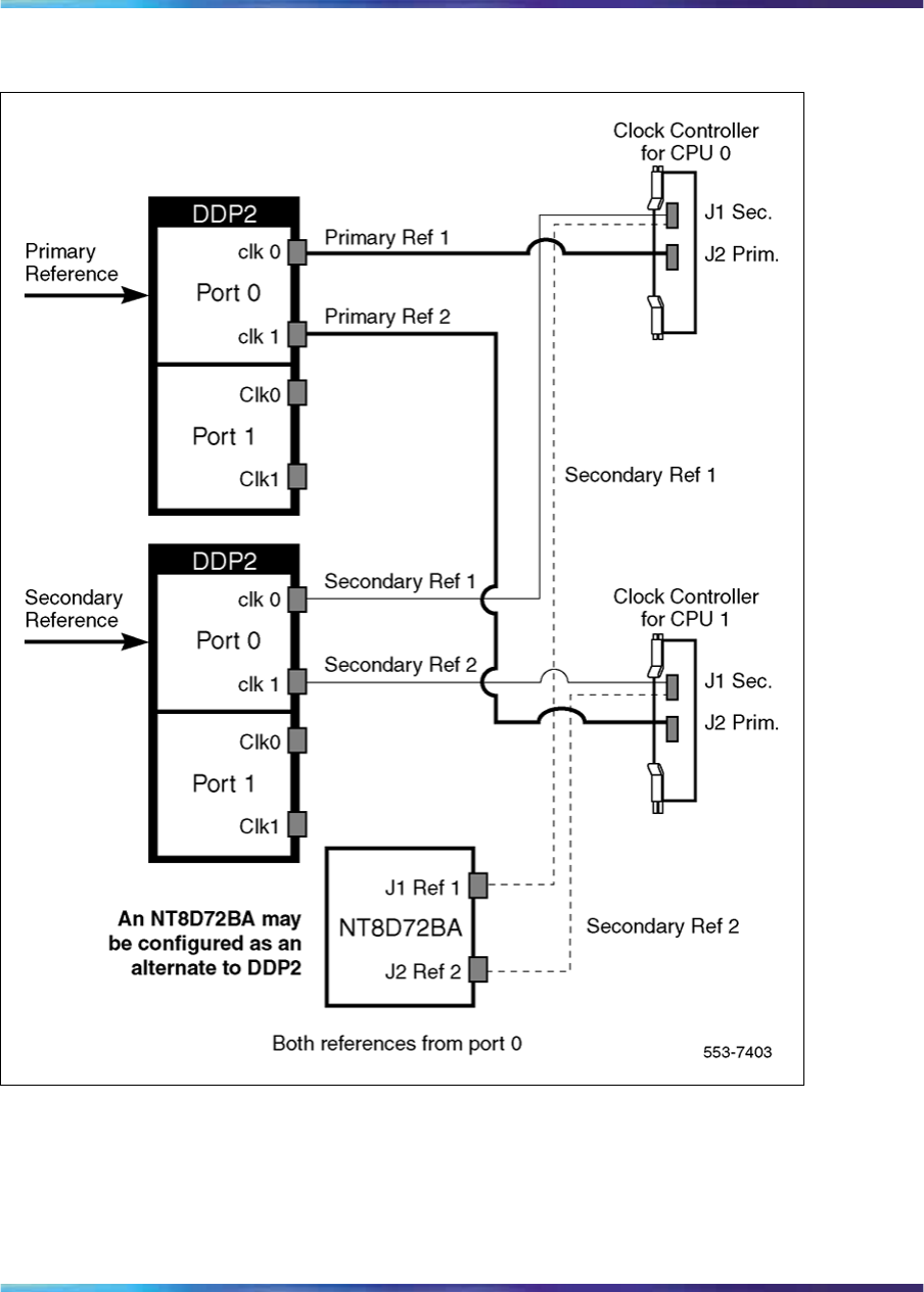
NT5D97 Dual-port DTI2/PRI2 card 55
Figure 20
Clock Controller - Option 2
Nortel Communication Server 1000
ISDN Primary Rate Interface Installation and Commissioning
NN43001-301 02.03 Standard
Release 5.5 7 December 2007
Copyright © 2003-2007, Nortel Networks
.
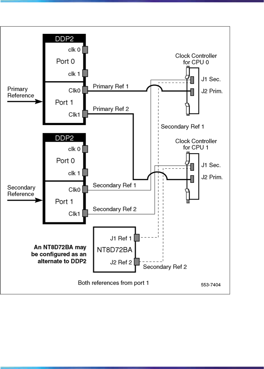
56 ISDN Primary Rate Interface equipment overview
Figure 21
Clock Controller - Option 3
Nortel Communication Server 1000
ISDN Primary Rate Interface Installation and Commissioning
NN43001-301 02.03 Standard
Release 5.5 7 December 2007
Copyright © 2003-2007, Nortel Networks
.
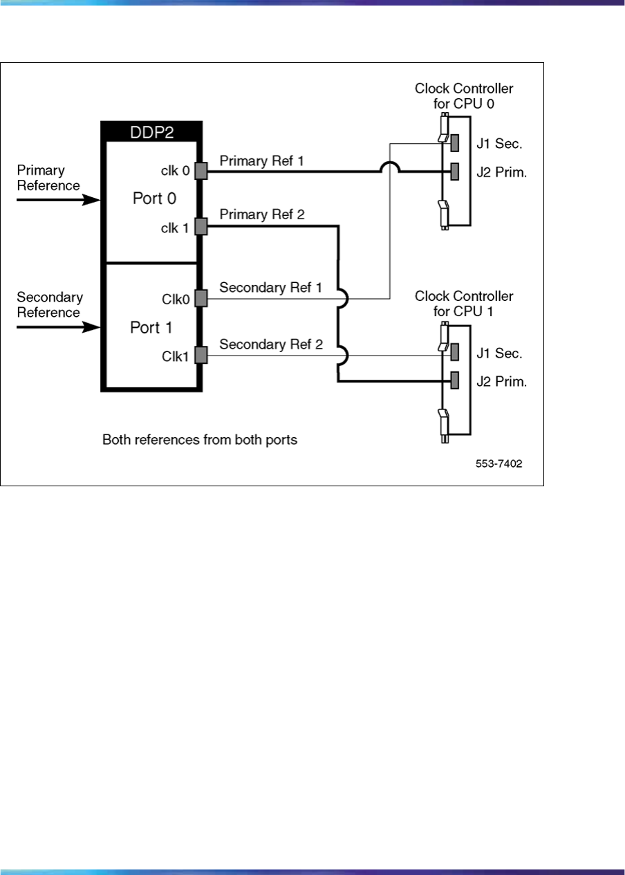
NT5D12 Dual-port DTI/PRI 57
Figure 22
Clock Controller - Option 4
NT5D12 Dual-port DTI/PRI
The NT5D12 is a dual-port 1.5 DTI/PRI card (the DDP firmware functions in
DTI or PRI mode) integrating the functionality of two QPC472 DTI/DDP2
PRI cards and one QPC414 ENET into one card. The NT5D12 occupies a
single Network shelf slot and provides two DTI/PRI network connections,
an optional connection to an external D-Channel Handler, the QPC757
D-Channel Handler Interface (DCHI) or NT6D80 Multipurpose Serial Data
Link (MSDL), and an optional plug-on NTBK51AA Downloadable D-Channel
daughterboard (DDCH.)
The NT5D12 DDP card supports all features (except the echo canceller and
protocol conversion) of the QPC720. In addition, it maintains the backward
compatibility of QPC720.
The NT5D12 DDP card hardware design uses a B57 ASIC E1/T1 framer.
The carrier specifications comply with the ANSI TI.403 specification. The
NT5D12 provides an interface to the 1.5 Mb external digital line either
directly or through an office repeater, Line Terminating Unit (LTU), or
Channel Service Unit (CSU).
Nortel Communication Server 1000
ISDN Primary Rate Interface Installation and Commissioning
NN43001-301 02.03 Standard
Release 5.5 7 December 2007
Copyright © 2003-2007, Nortel Networks
.

58 ISDN Primary Rate Interface equipment overview
D-Channel and MSDL interface
The connection between the DDP card and the DCHI or MSDL is via a 26
pin female D type connector. The data signals conform to the electrical
characteristics of the EIA standard RS-422.
Two control signals are used to communicate the D-Channel link status
to the DCHI or MSDL. These are:
•Receiver Ready (RR), originating at the DDP card, to indicate to the
DCHI or MSDL that the D-channel link is operational.
•Transmitter Ready (TR), originating at the DCHI or MSDL, to indicate to
the DDP card that the DCHI or MSDL are ready to use the D-Channel
link.
Table 15 "DCHI/MSDL Receiver Ready control signals" (page 58) indicates
how the RR control signal operates with regard to the DDP status.
Table 15
DCHI/MSDL Receiver Ready control signals
RR State Condition
ON D-Channel data rate selected at 64 Kbps or 56 Kbps or 64 Kbps
inverted
and
PRI loop is enabled
and
PRI link is not in RED alarm mode state
and
PRI link is not transmitting a yellow alarm pattern
and
PRI link is not receiving a Remote Alarm Indication from the
remote facility
and
PRI link is not in FA3 mode
Nortel Communication Server 1000
ISDN Primary Rate Interface Installation and Commissioning
NN43001-301 02.03 Standard
Release 5.5 7 December 2007
Copyright © 2003-2007, Nortel Networks
.

NT5D12 Dual-port DTI/PRI 59
RR State Condition
and
Transmitter Ready (TR) control signal from the DCHI/MSDL is
ON
OFF All other conditions
NT5D12 faceplate
Figure 23 "NT5D12 faceplate - general view" (page 60) and Figure 24
"DDP faceplate - detailed view" (page 61) illustrate the faceplate layout
for the NT5D12 DDP card. The faceplate contains an enable/disable
switch; a DDCH status LED; 6 x 2 trunk port status LEDs; and six external
connectors. Table 7 "External connectors and LEDs" (page 36) shows the
name of each connector, its designation with respect to the faceplate and
the name and description of the card it is connected to. Also shown are the
names of the LEDs.
Nortel Communication Server 1000
ISDN Primary Rate Interface Installation and Commissioning
NN43001-301 02.03 Standard
Release 5.5 7 December 2007
Copyright © 2003-2007, Nortel Networks
.
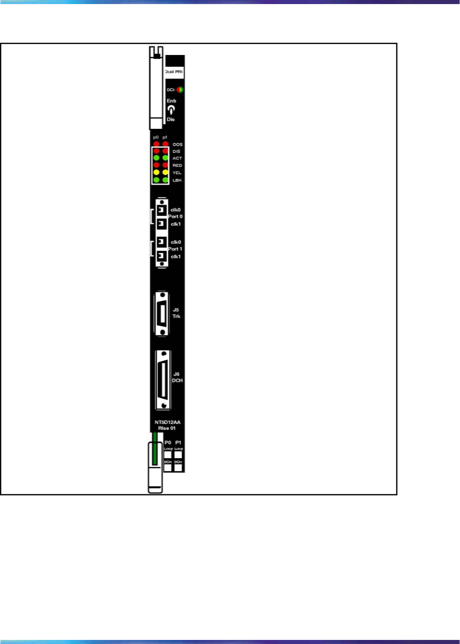
60 ISDN Primary Rate Interface equipment overview
Figure 23
NT5D12 faceplate - general view
Nortel Communication Server 1000
ISDN Primary Rate Interface Installation and Commissioning
NN43001-301 02.03 Standard
Release 5.5 7 December 2007
Copyright © 2003-2007, Nortel Networks
.

NT5D12 Dual-port DTI/PRI 61
Figure 24
DDP faceplate - detailed view
Table 16
External connectors and LEDs
Function Faceplate
Designator Type Description
Switch ENB/DIS Plastic, ESD
protected Card Enable/disable switch
Nortel Communication Server 1000
ISDN Primary Rate Interface Installation and Commissioning
NN43001-301 02.03 Standard
Release 5.5 7 December 2007
Copyright © 2003-2007, Nortel Networks
.

62 ISDN Primary Rate Interface equipment overview
Function Faceplate
Designator Type Description
Port 0 Clock 0 RJ11 Connector Connects reference clock to
Clock Controller card
Port 0 Clock 1 RJ11 Connector Connects reference clock to
Clock Controller card
Port 1 Clock 0 RJ11 Connector Connects reference clock to
Clock Controller card
Connectors Port 1 Clock 1 RJ11 Connector Connects reference clock to
Clock Controller card
J5 TRK 9 Pin Female
D Connector
Two external DS-1 Trunk 0 and
Trunk 1
J6 DCH 26 Pin Female
D Connector
Connects to DCHI or MSDL
OOS 2 Red LEDs ENET 0 or ENET 1 disabled
DIS 2 Red LEDs Trunk 0 or Trunk 1 disabled
ACT 2 Green LEDs Trunk 0 or Trunk 1 lines active
RED 2 Red LEDs Red Alarm on Trunk 0 or Trunk 1
LEDs YEL 2 Yellow LEDs Yellow Alarm on Trunk 0 or Trunk
1
LBK 2 Green LEDs Loop Back test being performed
on Trunk 0 or Trunk 1
DCH Bicolor Red/Green LED NTBK51AA status
The following is a brief description of each element on the faceplate:
Enable/Disable Switch
This switch is used to disable the card prior to insertion or removal from
the network shelf; while this switch is in disable position, the card will not
respond to system CPU.
Port Out of Service LEDs
Two red LEDs indicate if the "ENET0" and "ENET1" portion of the card are
disabled. These LEDs are lit in the following cases:
•When the enable/disable switch is in state disable (lit by hardware)
•After power-up, before the card is enabled
•When the ENET port on the card is disabled by software.
Nortel Communication Server 1000
ISDN Primary Rate Interface Installation and Commissioning
NN43001-301 02.03 Standard
Release 5.5 7 December 2007
Copyright © 2003-2007, Nortel Networks
.

NT5D12 Dual-port DTI/PRI 63
Trunk Port Disable LEDs
Two red LEDs indicate if the "trunk port 0" and "trunk port 1" portion of the
card are disabled. These LEDs are turned on in the following cases:
•When the enable/disable switch is in state disable (lit by hardware).
•After power-up, before the card is enabled.
•When digital trunk interface on the card is deactivated by software.
ACT LEDs
Two green LEDs indicate if the "trunk port 0" and "trunk port 1" portion
of the card is active.
RED LEDs
Two red LEDs indicate if the near end detects absence of incoming signal
or loss of synchronization in "trunk port 0" or "trunk port 1" respectively.
The Near End Alarm causes a Far End Alarm signal to be transmitted to
the far end.
YEL LEDs
Two yellow LEDs indicate if a Far End Alarm has been reported by the far
end (usually in response to a Near End Alarm condition at the far end)
on "trunk port 0" or "trunk port 1".
LBK LEDs
Two green LEDs indicate the remote loopback test is being performed on
trunk port 0 or trunk port 1. The loopback indication is active when the
digital trunk is in remote loopback mode (T1 signals received from the far
end are regenerated and transmitted to the far end.) Normal call processing
is inhibited during remote loopback test.
DCH LED
A dual color red/green LED indicates that the onboard DDCH is present
but disabled (red), or is present and enabled (green). If a DDCH is not
configured on the DDP card, this lamp is not lit.
Port 0 Clk Connectors
Two RJ11 connectors for connecting:
•Digital trunk port 0 recovered clock to primary or secondary reference
source on clock controller card 0.
•Digital trunk port 0 recovered clock to primary or secondary reference
source on clock controller card 1.
Nortel Communication Server 1000
ISDN Primary Rate Interface Installation and Commissioning
NN43001-301 02.03 Standard
Release 5.5 7 December 2007
Copyright © 2003-2007, Nortel Networks
.

64 ISDN Primary Rate Interface equipment overview
Port 1 Clk Connectors
Two RJ11 connectors for connecting:
•Digital trunk port 1 recovered clock to primary or secondary reference
source on clock controller card 0.
•Digital trunk port 1 recovered clock to primary or secondary reference
source on clock controller card 1.
Connector J5 (TRK)
A 9 pin D-Type connector used to connect:
•Digital trunk port 0 receive and transmit Tip / Ring pairs.
•Digital trunk port 1 receive and transmit Tip / Ring pairs.
Connector J6 (DCH)
A 26 pin D-type connector, used to connect the DDP card to MSDL or
QPC757 external D-channel handlers.
System capacity and performance
Physical capacity
Each DDP card occupies one slot on the network shelf. It supports two
digital trunk circuits and two network loops. The total number of DDP cards
per system is limited by the number of network loops, physical capacity of
the shelf, number of DTI/PRI interfaces allowed by the software and the
range of DCH addresses.
D-Channel capacity
The software configuration for the NTBK51AA DDCH is similar to the MSDL.
It is both physical and logical, and supports D-Channel functionality only.
The system has a total capacity of 16 addresses (Device Addresses or
DNUM) that can be reserved for DCHI card, MSDL card or DDCH card. One
exception is DNUM 0 which is commonly assigned to the System Monitor.
No two different D-Channel providers can share the same DNUM. Hence,
the combined maximum number of DCHI, MSDL and DDCH cards in the
system is 16.
The DCHI and DDCH have two D-Channel units, the MSDL has four.
Therefore the total number of D-Channels is derived by the following formula:
Total_Num_DCH-Units = Num_DCHIx2 + Num_DDCHx2 + Num_MSDLx4
Therefore, Total_Num_DCH-Units in any given system is between 0-63.
Nortel Communication Server 1000
ISDN Primary Rate Interface Installation and Commissioning
NN43001-301 02.03 Standard
Release 5.5 7 December 2007
Copyright © 2003-2007, Nortel Networks
.
NT5D12 Dual-port DTI/PRI 65
CPU capacity
Using a NT512 DDP card instead of DTI/PRI cards does not increase
the load on the system CPU. The DDP replaces an ENET card and two
DTI/PRI cards, it emulates the ENET card and the overall CPU capacity is
not impacted by usage of DDP card instead of a DTI/PRI card.
Power requirements
Table 17 "DDP power requirements" (page 65) lists the power requirements
for the DDP card.
Table 17
DDP power requirements
Voltage Source Current
DDP (without
NTBK51AA) DDP (with
NTBK51AA)
+5V Backplane 3A 3.8A
+12V Backplane 25mA 75mA
-12V Backplane 25mA 75mA
Total Power (Maximum) 15.6W 20.8W
Testability and diagnostics
The DDP card supports all current QPC720 testing and maintenance
functions through the following procedures:
•Self test upon power up or reset;
•Signaling test performed in the LD 30;
•Loopback tests, self tests, and continuity tests performed by LD 60 and
LD 45;
•The D-Channel (MSDL, DCHI, DDCH) maintenance is supported by
LD 96.
NT5D12 Cable requirements
This section lists the types of cable used and the lengths required for
internal and external NT5D12 DDP connections.
Note 1: No additional cabling is required for nB+D configurations.
Multiple DDPs and the D-channel are associated through software in
LD 17.
Note 2: A detailed discussion of each type of DDP cable listed below
follows.
Nortel Communication Server 1000
ISDN Primary Rate Interface Installation and Commissioning
NN43001-301 02.03 Standard
Release 5.5 7 December 2007
Copyright © 2003-2007, Nortel Networks
.

66 ISDN Primary Rate Interface equipment overview
New DDP cable assemblies include:
•System Trunk Tip/Ring Cables
— NT5D16AA
— NT5D17AA
— QCAD133
•DDP to QPC471/QPC775 Clock Controller Cables
— NTCG03AA
— NTCG03AB
— NTCG03AC
— NTCG03AD
•DDP to DCHI cables
— NTCK46AA
— NTCK46AB
— NTCK46AC
— NTCK46AD
•DDP to MSDL cables
— NTCK80AA
— NTCK80AB
— NTCK80AC
— NTCK80AD
Trunk Tip/Ring cables
NT5D16AA
The NT5D16AA (8 ft.) is a 100W cable for systems equipped with an I/O
filter panel, connecting the 9 pin D-type TRK port on the DDP faceplate
to the I/O filter.
Note: On the I/O panel side, this cable is equipped with a monitor
bantam plug and a 15 pin D-type trunk connector mounted on a small
PCB. There are no bantam plugs on the DDP faceplate.
Nortel Communication Server 1000
ISDN Primary Rate Interface Installation and Commissioning
NN43001-301 02.03 Standard
Release 5.5 7 December 2007
Copyright © 2003-2007, Nortel Networks
.
NT5D12 Dual-port DTI/PRI 67
Figure 25
NT5D16AA
Table 18 "NT5D16AA cable pins" (page 67) lists the pin attributes for the
NT5D16AA cable.
Table 18
NT5D16AA cable pins
Cable Name Description Color DDP
pins (J5) I/O Panel
pins (J2, J3)
0T-PRI0TX Trunk 0 Transmit Tip Black J5-1 P0J3-1
P0J2-3
0R-PRI0TX Trunk 0 Transmit Ring Red J5-2 P0J3-9
P0J2-9
0T-PRI0RX Trunk 0 Receive Tip Black J5-3 P0J3-3
P0J2-4
0R-PRI0RX Trunk 0 Receive Ring White J5-4 P0J3-11
P0J2-10
0GND Shield Wire Bare N/C Case P0
0GND Shield Wire Bare N/C Case P0
1T-PRI1TX Trunk 1 Transmit Tip Black J5-5 P1J3-1
P1J2-3
1R-PRI1TX Trunk 1 Transmit Ring Red J5-6 P1J3-9
P1J2-9
1T-PRI1RX Trunk 1 Receive Tip Black J5-7 P1J3-3
P1J2-4
Nortel Communication Server 1000
ISDN Primary Rate Interface Installation and Commissioning
NN43001-301 02.03 Standard
Release 5.5 7 December 2007
Copyright © 2003-2007, Nortel Networks
.
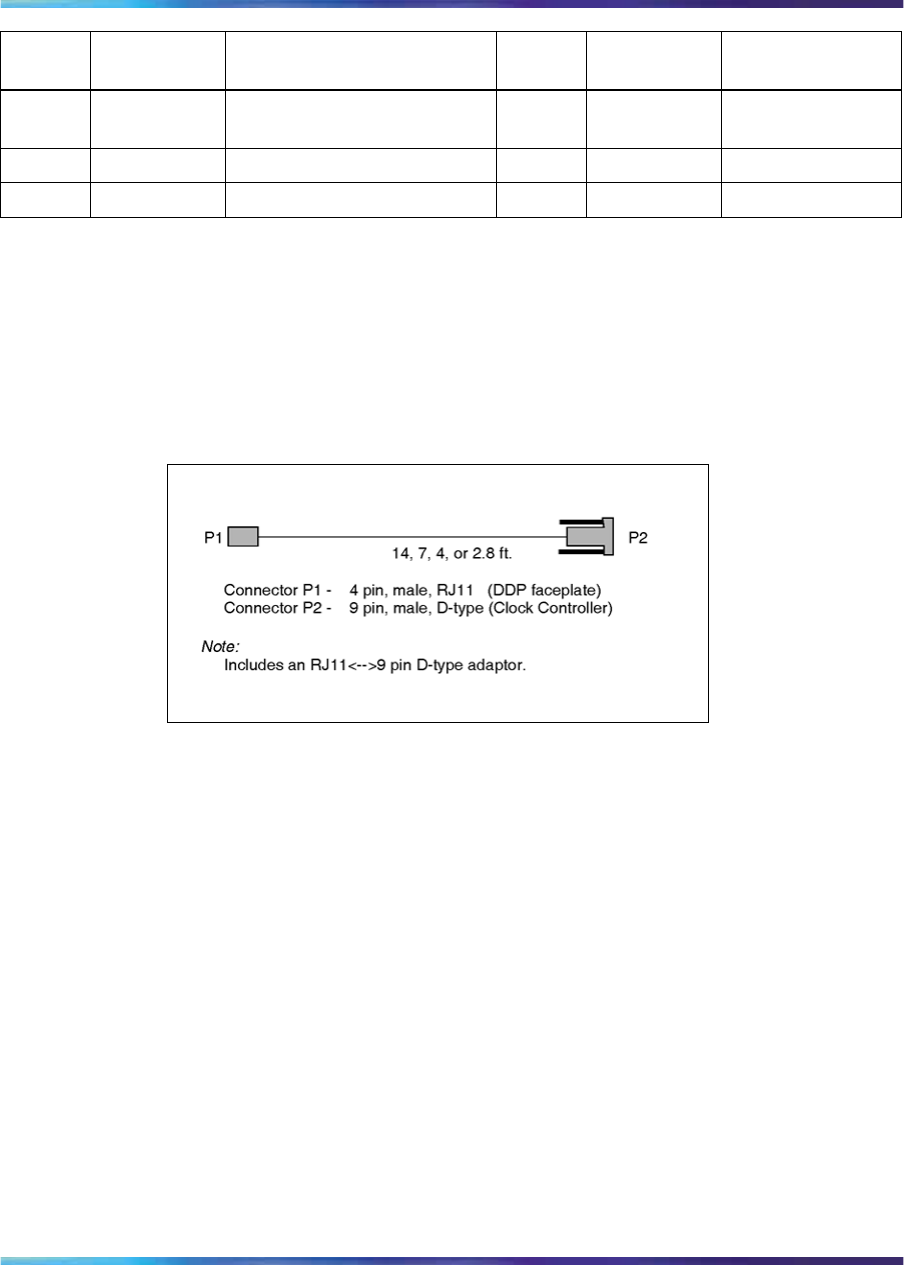
68 ISDN Primary Rate Interface equipment overview
Cable Name Description Color DDP
pins (J5) I/O Panel
pins (J2, J3)
1R-PRI1RX Trunk 1 Receive Ring White J5-8 P1J3-11
P1J2-10
1GND Shield Wire Bare N/C Case P1
1GND Shield Wire Bare N/C Case P1
Reference clock cables
The NTCG03AA (14 ft.), NTCG03AB (2.8 ft.), NTCG03AC (4.0 ft.), or
NTCG03AD (7 ft.) is a DDP card to Clock Controller cable, connecting
each of the CLK0 or CLK1 ports on the DDP faceplate to the primary or
secondary source ports on Clock Controller card 0 or 1.
Figure 26
NTCG03AA, NTCG03AB, NTCG03AC, or NTCG03AD
MSDL/DCHI cables
External DCHI cable
The NTCK46 cable connects the DDP card to the QPC757 DCHI D-Channel
Handler card. The cable is available in four different sizes:
•NTCK46AA (6 ft.) - DDP to DCHI cable
•NTCK46AB (18 ft.) - DDP to DCHI cable
•NTCK46AC (35 ft.) - DDP to DCHI cable
•NTCK46AD (50 ft.) - DDP to DCHI cable
Nortel Communication Server 1000
ISDN Primary Rate Interface Installation and Commissioning
NN43001-301 02.03 Standard
Release 5.5 7 December 2007
Copyright © 2003-2007, Nortel Networks
.
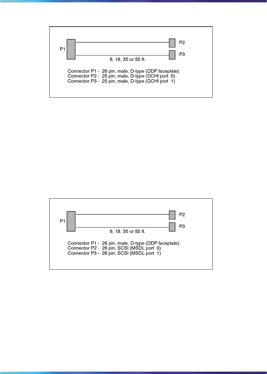
NT5D12 Dual-port DTI/PRI 69
Figure 27
NTCK46AA, NTCK46AB, NTCK46AC, NTCK46AD
External MSDL cable
The NTCK80 cable connects the DDP card to the NT6D80 MSDL card. The
cable is available in four different sizes:
•NTCK80AA (6 ft.) - DDP to MSDL cable
•NTCK80AB (18 ft.) - DDP to MSDL cable
•NTCK80AC (35 ft.) - DDP to MSDL cable
•NTCK80AD (50 ft.) - DDP to MSDL cable
Figure 28
NTCK80AA, NTCK80AB, NTCK80AC, NTCK80AD
Cable diagrams
Figure 29 "DDP cable for systems with an I/O panel" (page 70) provides an
example of a typical cabling configuration for the DDP. Please note that
these figures are representational only, and are not intended to show the
relational card slot position of the various cards.
Figure 29 "DDP cable for systems with an I/O panel" (page 70) shows
a typical DDP cabling for a system Option with an I/O panel, with the
connection between the I/O panel and a Network Channel Terminating
Equipment (NCTE).
Nortel Communication Server 1000
ISDN Primary Rate Interface Installation and Commissioning
NN43001-301 02.03 Standard
Release 5.5 7 December 2007
Copyright © 2003-2007, Nortel Networks
.
70 ISDN Primary Rate Interface equipment overview
Note: Since there exists several clock cabling options, none has been
represented in the diagram. Please refer to "Clock configurations" (page
72) for a description on each available option.
Figure 29
DDP cable for systems with an I/O panel
Clock There are two types of clock operation - tracking mode and free-run mode.
Tracking mode
In tracking mode, the DDP loop supplies an external clock reference to a
clock controller. Two DDP loops can operate in tracking mode, with one
defined as the primary reference source for clock synchronization, the other
defined as the secondary reference source. The secondary reference acts
as a back-up to the primary reference.
Nortel Communication Server 1000
ISDN Primary Rate Interface Installation and Commissioning
NN43001-301 02.03 Standard
Release 5.5 7 December 2007
Copyright © 2003-2007, Nortel Networks
.
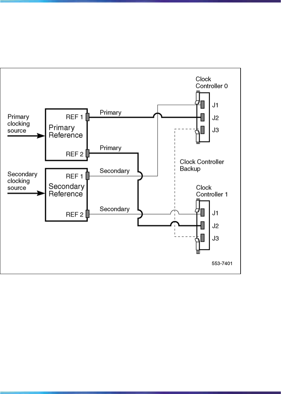
NT5D12 Dual-port DTI/PRI 71
As shown in Figure 30 "Clock Controller primary and secondary tracking"
(page 71), a system with dual CPUs can have two clock controllers (CC-0
and CC-1). One clock controller acts as a back-up to the other. Lock the
clock controllers to the reference clock.
Figure 30
Clock Controller primary and secondary tracking
Free run (non-tracking) mode
The clock synchronization of the system can operate in free-run mode if:
•no loop is defined as the primary or secondary clock reference,
•the primary and secondary references are disabled, or
•the primary and secondary references are in local (near end) alarm.
Reference clock errors
The system software checks at intervals of 1 to 15 minutes to see if a clock
controller or reference-clock error has occurred. (The interval of this check
can be configured in LD 73.)
Nortel Communication Server 1000
ISDN Primary Rate Interface Installation and Commissioning
NN43001-301 02.03 Standard
Release 5.5 7 December 2007
Copyright © 2003-2007, Nortel Networks
.

72 ISDN Primary Rate Interface equipment overview
In tracking mode, at any one time, there is one active clock controller which
is tracking on one reference clock. If a clock controller error is detected, the
system switches to the back-up clock controller, without affecting which
reference clock is being tracked.
A reference-clock error occurs when there is a problem with the clock driver
or with the reference clock at the far end. If the clock controller detects a
reference-clock error, the reference clocks are switched.
Automatic clock recovery
A command for automatic clock recovery can be selected in LD 60 with
the command EREF.
A DDP loop is disabled when it enters a local-alarm condition. If the local
alarm is cleared, the loop is enabled automatically. When the loop is
enabled, clock tracking is restored in the following conditions:
•If the loop is assigned as the primary reference clock but the clock
controller is tracking on the secondary reference or in free-run mode, it
is restored to tracking on primary.
•If the loop is assigned as the secondary reference clock but the clock
controller is in free-run mode, it is restored to tracking on secondary.
•If the clock check indicates the switch is in free-run mode:
— Tracking is restored to the primary reference clock if defined.
— If the primary reference is disabled or in local alarm, tracking is
restored to the secondary reference clock if defined.
Note: If the system is put into free-run mode by the craftsperson,
it resumes tracking on a reference clock unless the clock-switching
option is disabled (LD 60, command MREF), or the reference clock is
"undefined" in the database.
Automatic clock switching
If the EREF command is selected in LD 60, tracking on the primary or
secondary reference clock is automatically switched in the following manner:
•If software is unable to track on the assigned primary reference clock, it
switches to the secondary reference clock and sends appropriate DTC
maintenance messages.
•If software is unable to track on the assigned secondary reference clock,
it switches to free run.
Clock configurations
Clock Controllers can be used in a single or a dual CPU system.
Nortel Communication Server 1000
ISDN Primary Rate Interface Installation and Commissioning
NN43001-301 02.03 Standard
Release 5.5 7 December 2007
Copyright © 2003-2007, Nortel Networks
.

NT5D12 Dual-port DTI/PRI 73
A single CPU system has one Clock Controller card. This card can receive
reference clocks from two sources referred to as the primary and secondary
sources. These two sources can originate from a PRI, DTI, etc. PRI cards
such as the QPC720 are capable of supplying two references of the same
clock source. These are known as Ref1 (available at J1) and Ref2 (available
at J2) on the QPC720.
The NT5D12 card is capable of supplying two references from each clock
source, i.e., four references in total. NT5D12 can thus supply Clk0 and Clk1
from Port 0 and Clk0 and Clk1 from Port 1. Either Port 0 or Port 1 can
originate the primary source, as shown in Figure 31 "Clock Controller -
Option 1" (page 75) through Figure 34 "Clock Controller - Option 4" (page
78) to Figure 34 "Clock Controller - Option 4" (page 78).
There is one new Clock Controller cable required for the new DDP card,
which is available in four sizes; this is the NTCG03AA/AB/AC/AD. Refer to
"Reference clock cables" (page 68) for more information.
"Reference clock cables" (page 45) summarizes the clock options. Table
20 "Clock Controller options - description" (page 74) explains the options in
more detail.
Table 19
Clock Controller options- summary
CC Option CPU Type Notes
Option 1 Single Ref from P0 on Clk0
Ref from P1 on Clk0
Option 2 Dual Ref from P0 on Clk0
Ref from P0 on Clk1
Option 3 Dual Ref from P1 on Clk0
Ref from P1 on Clk1
Option 4 Dual Ref from P0 on Clk0
Ref from P0 on Clk1
Ref from P1 on Clk0
Ref from P1 on Clk1
Nortel Communication Server 1000
ISDN Primary Rate Interface Installation and Commissioning
NN43001-301 02.03 Standard
Release 5.5 7 December 2007
Copyright © 2003-2007, Nortel Networks
.

74 ISDN Primary Rate Interface equipment overview
Table 20
Clock Controller options - description
Clock Option Notes
Option 1 This option provides a single CPU system with 2 clock sources
derived from the 2 ports of the DDP.
Connector Clk0 provides a clock source from Port 0.
Connector Clk0 provides a clock source from Port 1.
Refer to Figure 31 "Clock Controller - Option 1" (page 75)
Option 2 This option provides a Dual CPU system with 2 references of a
clock source derived from port 0 of the DDP.
Connector Clk0 provides a Ref 1 clock source from Port 0.
Connector Clk1 provides a Ref 2 clock source from Port 0.
Refer to Figure 32 "Clock Controller - Option 2" (page 76)
Option 3 This option provides a Dual CPU system with 2 references of a
clock source derived from port 1 of the DDP.
Connector Clk0 provides a Ref 1 clock source from Port 1.
Connector Clk1 provides a Ref 2 clock source from Port 1.
Refer to Figure 33 "Clock Controller - Option 3" (page 77)
Option 4 This option provides a Dual CPU system with 2 references from
each clock source derived from the DDP.
Connector Clk0 provides a Ref 1 clock source from Port 0.
Connector Clk1 provides a Ref 2 clock source from Port 0.
Connector Clk0 provides a Ref 1 clock source from Port 1.
Connector Clk1 provides a Ref 2 clock source from Port 1.
Refer to Figure 34 "Clock Controller - Option 4" (page 78)
Nortel Communication Server 1000
ISDN Primary Rate Interface Installation and Commissioning
NN43001-301 02.03 Standard
Release 5.5 7 December 2007
Copyright © 2003-2007, Nortel Networks
.
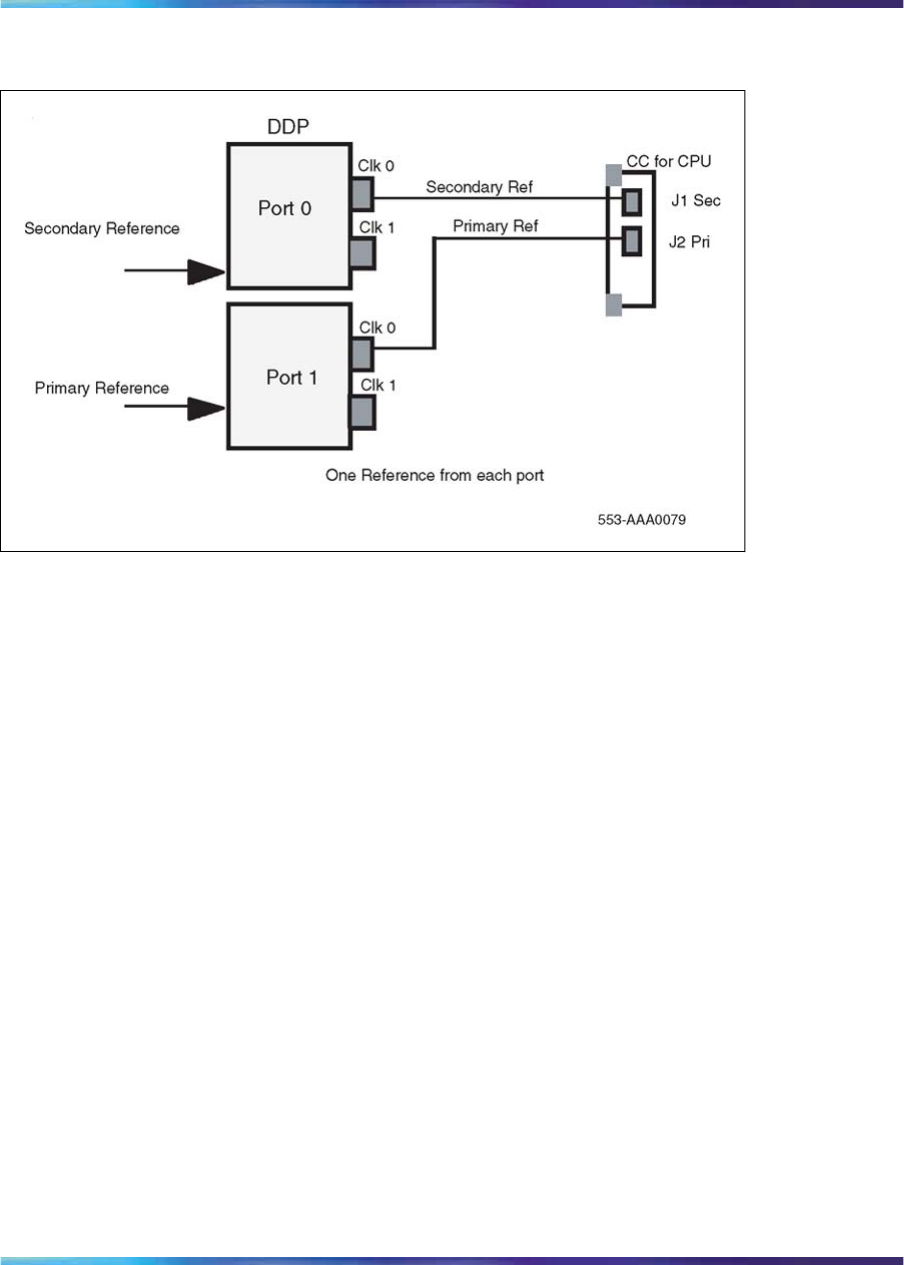
NT5D12 Dual-port DTI/PRI 75
Figure 31
Clock Controller - Option 1
Nortel Communication Server 1000
ISDN Primary Rate Interface Installation and Commissioning
NN43001-301 02.03 Standard
Release 5.5 7 December 2007
Copyright © 2003-2007, Nortel Networks
.

76 ISDN Primary Rate Interface equipment overview
Figure 32
Clock Controller - Option 2
Nortel Communication Server 1000
ISDN Primary Rate Interface Installation and Commissioning
NN43001-301 02.03 Standard
Release 5.5 7 December 2007
Copyright © 2003-2007, Nortel Networks
.
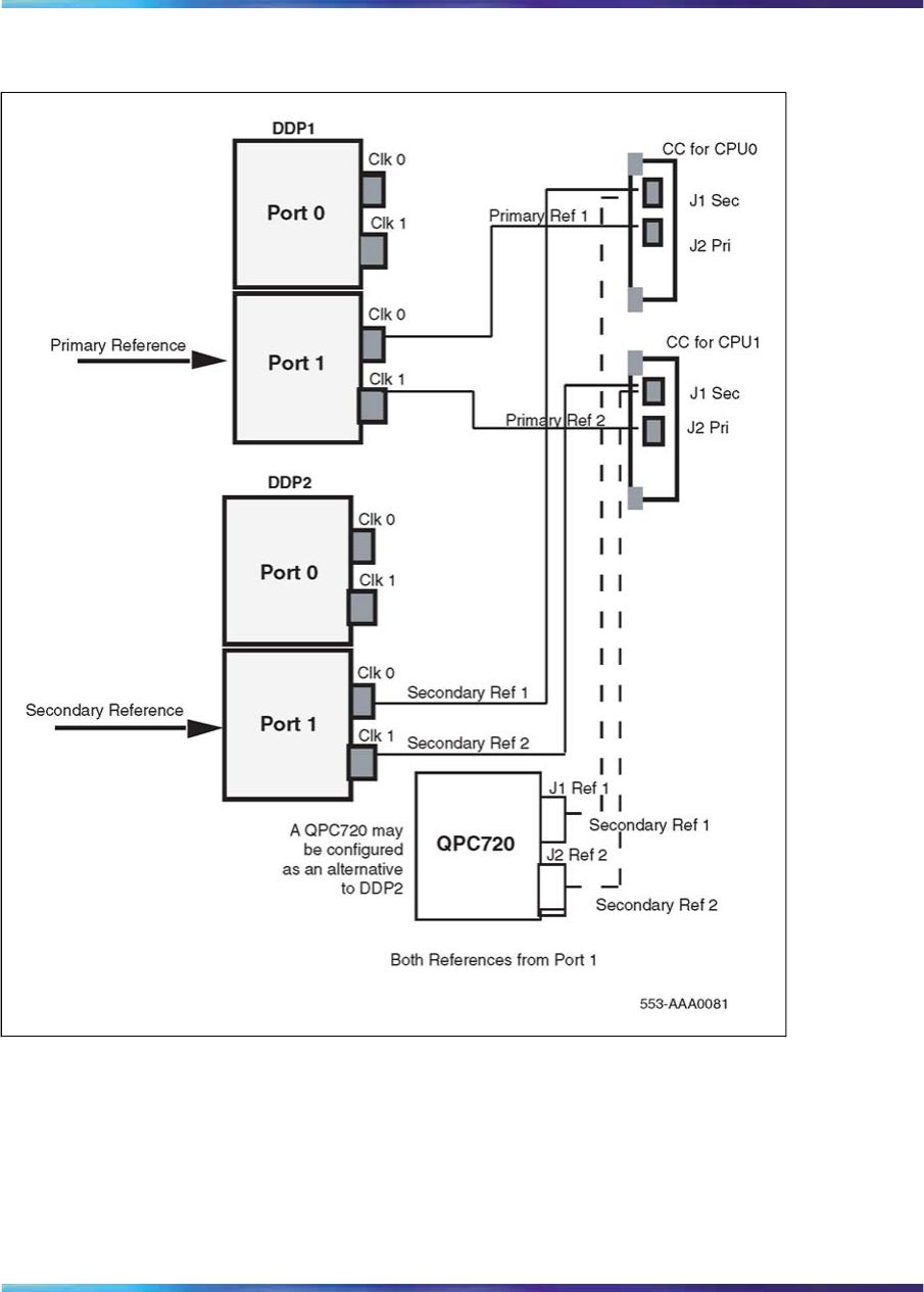
NT5D12 Dual-port DTI/PRI 77
Figure 33
Clock Controller - Option 3
Nortel Communication Server 1000
ISDN Primary Rate Interface Installation and Commissioning
NN43001-301 02.03 Standard
Release 5.5 7 December 2007
Copyright © 2003-2007, Nortel Networks
.
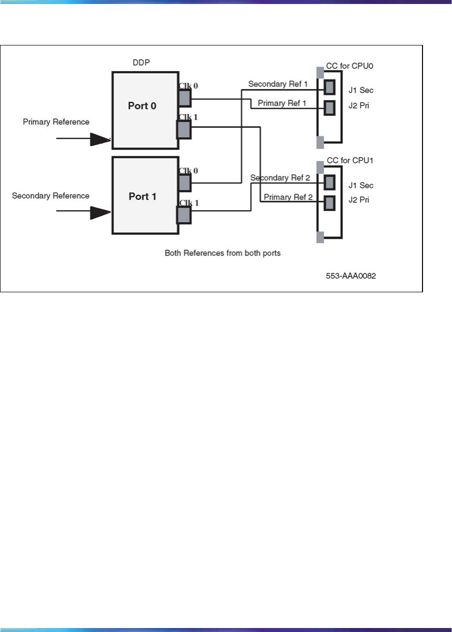
78 ISDN Primary Rate Interface equipment overview
Figure 34
Clock Controller - Option 4
Nortel Communication Server 1000
ISDN Primary Rate Interface Installation and Commissioning
NN43001-301 02.03 Standard
Release 5.5 7 December 2007
Copyright © 2003-2007, Nortel Networks
.

79
DCH installation
Contents The section contains information on the following topics:
"Install the NT6D11AB, NT6D11AE, NT6D11AF DCH" (page 79)
"Install the NT6D11AB, NT6D11AE, NT6D11AF DCH" (page 79)
"Set up the NT6D11AB, NT6D11AE, NT6D11AF DCHI" (page 80)
"DIP switch settings" (page 80)
"Protocol selection" (page 80)
"Valid switch combinations" (page 81)
"Jumper settings" (page 82)
"Port addressing modes" (page 83)
"Port address switch settings" (page 84)
"Install the NT6D11AB, NT6D11AE, NT6D11AF DCHI" (page 85)
"Remove the NT6D11AB, NT6D11AE, NT6D11AF DCH" (page 86)
"Install the QPC757 DCH" (page 87)
"Port address switch settings" (page 89)
"D-channel parameter downloading" (page 90)
"Remove the QPC757 DCHI" (page 90)
Install the NT6D11AB, NT6D11AE, NT6D11AF DCH
Installation procedures for the NT6D11AB, NT6D11AE, and NT6D11AE
DCHI cards are the same for all Large Systems. These instructions apply to
hardware both for primary and backup D-channels. D-channel lines must be
conditioned for 64K before D-channels can be brought up.
Note: To configure J1, the asynchronous port on the DCHI card, refer
to the documentation of the application being interfaced, and to Circuit
Card Reference (NN43001-311). J1 configuration is not described in
this technical document.
Nortel Communication Server 1000
ISDN Primary Rate Interface Installation and Commissioning
NN43001-301 02.03 Standard
Release 5.5 7 December 2007
Copyright © 2003-2007, Nortel Networks
.
80 DCH installation
Set up the NT6D11AB, NT6D11AE, NT6D11AF DCHI
DIP switch settings
The NT6D11AB/AE/AF has three sets of DIP switches. Each port has its
own bank of 10 DIP switches (SW1 & SW2) to select the port address (8
bits) and mode of operation (2 bits). SW1 is used for port 0 settings, SW2 is
used for port 1 settings. SW3 is used to select the D-channel protocol. Port
0 is used to select whether the asynchronous ESDI port is be disabled or
not. Port 1 is used to select the standard or expanded D-channel addressing
mode on the NT6D11AB/AE/AF.
The DIP switches are located as shown by Figure 35 "NT6D11 DIP
switches" (page 80).
Figure 35
NT6D11 DIP switches
Protocol selection
SW3 is used to select the D-channel protocol, as shown by Table 21
"Protocol selection switch settings" (page 81).
Note: The setting must be 1 for ISDN applications.
Nortel Communication Server 1000
ISDN Primary Rate Interface Installation and Commissioning
NN43001-301 02.03 Standard
Release 5.5 7 December 2007
Copyright © 2003-2007, Nortel Networks
.
Set up the NT6D11AB, NT6D11AE, NT6D11AF DCHI 81
Table 21
Protocol selection switch settings
Protocol Switch Setting
SW3.1 SW3.2
DPNSS1 00
ISDN 11
Valid switch combinations
The following are the only allowable switch setting combinations (not
including address switch settings).
Port 0
Port 0 can be configured as asynchronous ESDI, or disabled. If the port is
configured as disabled, it will not be visible to the system CPU. Refer to
Table 22 "Port 0 settings" (page 81).
Table 22
Port 0 settings
Mode Switch setting
SW1.1 SW1.2 SW3.1 SW3.2
Asynchronous ESDI 1000
Asynchronous ESDI 1011
Port disabled 11--
Port 1
The following are the only valid emulation mode combinations. If the port
is configured as disabled, it will not be visible to the system CPU. Refer to
Table 23 "Port 1 settings" (page 81).
Note: The ISDN emulation must be selected.
Table 23
Port 1 settings
Mode Emulates Switch setting
SW2.1 SW2.2 SW3.1 SW3.2
DPNSS1 NT5K35 0000
ISDN NT6D11 0011
Expanded
DPNSS1 NT5K75 0100
Port disabled 11--
Nortel Communication Server 1000
ISDN Primary Rate Interface Installation and Commissioning
NN43001-301 02.03 Standard
Release 5.5 7 December 2007
Copyright © 2003-2007, Nortel Networks
.
82 DCH installation
Jumper settings
The NT6D11AB/AE/AF has two banks of option straps, one for each port.
These select between DCE and DTE operation and whether the signalling
interface is RS232 or RS422. Refer to Figure 36 "NT6D11 DCH with
ISL high-speed programming jumper settings" (page 82) and Figure 37
"NT6D11 DCH with ISL low-speed programming jumper settings" (page 83).
Figure 36
NT6D11 DCH with ISL high-speed programming jumper settings
Nortel Communication Server 1000
ISDN Primary Rate Interface Installation and Commissioning
NN43001-301 02.03 Standard
Release 5.5 7 December 2007
Copyright © 2003-2007, Nortel Networks
.
Set up the NT6D11AB, NT6D11AE, NT6D11AF DCHI 83
Figure 37
NT6D11 DCH with ISL low-speed programming jumper settings
Port addressing modes
Port 0 Mode selection
Port 0 is used to select whether the asynchronous ESDI port is be disabled
or not. Refer to Table 24 "Port 0 mode selection" (page 83).
Note: The asynchronous ESDI port must be set to "disabled".
Table 24
Port 0 mode selection
Port Mode Switch Setting
SW1.1 SW1.2
Not used 0-
Asynchronous ESDI 10
Port disabled 11
Port 1 mode selection
Port 1 is used to select the standard or expanded D-channel addressing
mode on the NT6D11AB/AE/AF. Refer to Table 25 "Port 1 mode selection"
(page 84).
Nortel Communication Server 1000
ISDN Primary Rate Interface Installation and Commissioning
NN43001-301 02.03 Standard
Release 5.5 7 December 2007
Copyright © 2003-2007, Nortel Networks
.
84 DCH installation
Table 25
Port 1 mode selection
Port Mode Switch Setting
SW2.1 SW2.2
Synchronous, D-channel, standard addressing
Note: THIS SELECTION MUST BE MADE FOR
ISDN.
00
Synchronous, D-channel, expanded addressing 01
Not used 10
Port disabled 11
Port address switch settings
Port address switch settings in the standard mode, for ISDN
Table 26 "Port address switch settings for ISDN" (page 84) depicts the port
address switch settings that apply to SW1 or SW2, the D-channel port,
for ISDN mode.
Table 26
Port address switch settings for ISDN
Port Address Switch Setting
Half Group No. Device No.
S3 S4 S5 S6 S7 S8 S9 S10
0 0000000x
1 0000001x
2 0000010x
3 0000011x
4 0000100x
50000101x
6 0000110x
70000111x
8 0001000x
9 0001001x
10 0001010x
11 0001011x
12 0001100x
13 0001101x
Nortel Communication Server 1000
ISDN Primary Rate Interface Installation and Commissioning
NN43001-301 02.03 Standard
Release 5.5 7 December 2007
Copyright © 2003-2007, Nortel Networks
.
Install the NT6D11AB, NT6D11AE, NT6D11AF DCHI 85
Port Address Switch Setting
Half Group No. Device No.
S3 S4 S5 S6 S7 S8 S9 S10
14 0001110x
15 0 0 1
16-31 0 0 1
32-47 0 1 0
48-63 0 1 1
64-79 1 0 0
80-95 1 0 1
96-111 1 1 0
112-127 1 1 1
Install the NT6D11AB, NT6D11AE, NT6D11AF DCHI
Follow Procedure 1 "Install the NT6D11AB, NT6D11AE, NT6D11AF DCH"
(page 85) to install the NT6D11 DCH on the Large System.
Procedure 1
Install the NT6D11AB, NT6D11AE, NT6D11AF DCH
Step Action
1Determine the cabinet and shelf location for the circuit pack being
installed.
The NT6D11AB, NT6D11AE, or NT6D11AF DCHI card can be
installed in any slot appropriate for an I/O port card on a Network
shelf. (The NT6D11 DCHI card can be located on the Common
Equipment shelf only on single-CPU switches.)
2Unpack and inspect the card.
3Set the option switches on the DCHI card. For PRA capability, set
port J2 to odd. For ISL capability, set port J2 for high speed or low
speed operation (See Figure 36 "NT6D11 DCH with ISL high-speed
programming jumper settings" (page 82),Figure 37 "NT6D11 DCH
with ISL low-speed programming jumper settings" (page 83), and
Table 26 "Port address switch settings for ISDN" (page 84) starting
on Figure 36 "NT6D11 DCH with ISL high-speed programming
jumper settings" (page 82)).
4Set faceplate toggle switch to DISABLE.
Nortel Communication Server 1000
ISDN Primary Rate Interface Installation and Commissioning
NN43001-301 02.03 Standard
Release 5.5 7 December 2007
Copyright © 2003-2007, Nortel Networks
.
86 DCH installation
5Install the DCHI card into the assigned shelf and slot.
6Connect DCHI port J2 to the NT8D72AB or NT8D72BA PRI port J5
with a QCAD328A cable.
7Set faceplate toggle switch to ENABLE.
8Coordinate the start-up and verification of the DCHI with the start-up
of the PRI.
9Enable the DCHI card using LD 96, command ENL DCHI N.
—End—
Remove the NT6D11AB, NT6D11AE, NT6D11AF DCH
Use Procedure 2 "Remove the NT6D11AB, NT6D11AE, NT6D11AF DCH"
(page 86) to remove the NT6D11AB, NT6D11AE, NT6D11AF DCH from
a Large System.
CAUTION
The NT6D11AB, NT6D11AE, NT6D11AF DCH must be software
disabled before it is hardware disabled, or initialization will occur.
Procedure 2
Remove the NT6D11AB, NT6D11AE, NT6D11AF DCH
Step Action
1Disable the NT6D11AB, NT6D11AE, NT6D11AF DCHI using LD 96,
command DIS DCHI N.
2If asynchronous port J1 is enabled, it must also be software disabled,
using LD 37, or initialization will occur.
3If the circuit pack is being completely removed, not replaced, remove
data from memory.
4Determine the cabinet and shelf location of the card to be removed.
5Set faceplate toggle switch to DISABLE.
6Disconnect NT6D11AB, NT6D11AE, NT6D11AF DCHI cables.
7Remove NT6D11AB, NT6D11AE, NT6D11AF DCHI card.
8Pack and store the card.
Nortel Communication Server 1000
ISDN Primary Rate Interface Installation and Commissioning
NN43001-301 02.03 Standard
Release 5.5 7 December 2007
Copyright © 2003-2007, Nortel Networks
.

Install the QPC757 DCH 87
—End—
Install the QPC757 DCH
Installation procedures for the QPC757 DCHI card are the same for all Large
Systems. These procedures apply to both primary and backup D-channels.
See Figure 38 "QPC757 option and PRI/ISL high-speed programming
switch settings" (page 88) on page 115, Figure 39 "QPC757 option and
PRI/ISL low-speed programming switch settings" (page 89) and Table 27
"D-channel port address switch settings for PRI" (page 89), for option switch
settings per port number of the DCHI card, in Primary Rate Interface mode.
Use Procedure 3 "Install the QPC757 DCHI" (page 87) to install the
QPC757 DCHI card on Large Systems.
Procedure 3
Install the QPC757 DCHI
Step Action
1Determine the cabinet and shelf location of the circuit card to be
installed.
The QPC757 DCHI card can be installed in any slot appropriate
for an I/O port card on a network shelf. For single CPU systems
only, the QPC757 DCHI card can be located on the Common
Equipment (CE) shelf.
2Unpack and inspect the card.
3Set option switches and jumper plugs on the DCHI card. For PRI
capability, set port J2 to odd. For ISL capability, set port J2 for
high-speed or low-speed programming.
4Set faceplate toggle switch to DISABLE.
5Install DCHI card into the assigned shelf or module and slot.
6Run and connect DCHI cables: connect QPC757 J2 to QPC720
PRI J5 with a QCAD328A cable.
7Set faceplate toggle switch to ENABLE.
8Enable the loop in LD 60.
9Coordinate start-up and verification of the DCHI with the start-up
of the PRI.
10 Enable the DCHI card using LD 96, command ENL DCH x.
Nortel Communication Server 1000
ISDN Primary Rate Interface Installation and Commissioning
NN43001-301 02.03 Standard
Release 5.5 7 December 2007
Copyright © 2003-2007, Nortel Networks
.
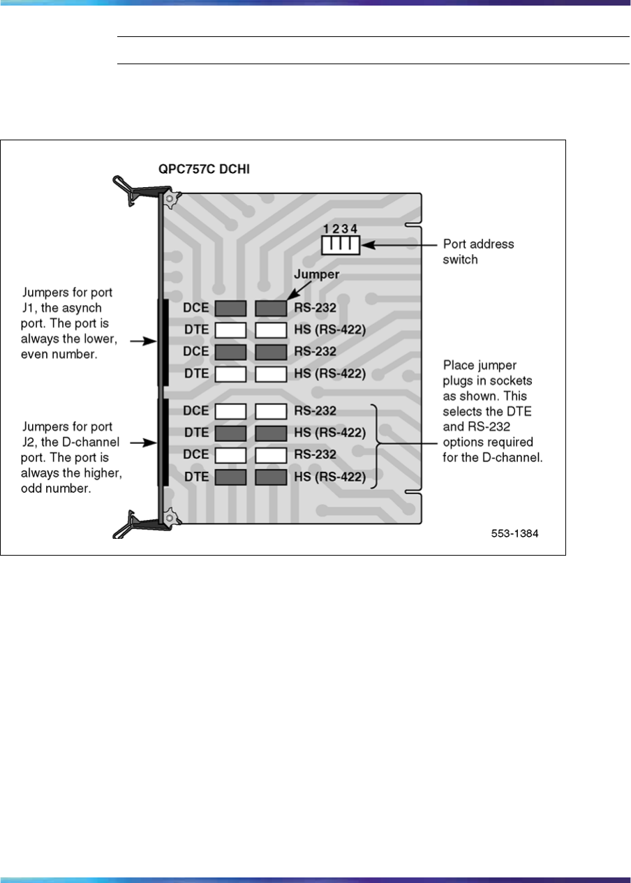
88 DCH installation
—End—
Figure 38
QPC757 option and PRI/ISL high-speed programming switch settings
Nortel Communication Server 1000
ISDN Primary Rate Interface Installation and Commissioning
NN43001-301 02.03 Standard
Release 5.5 7 December 2007
Copyright © 2003-2007, Nortel Networks
.
Install the QPC757 DCH 89
Figure 39
QPC757 option and PRI/ISL low-speed programming switch settings
Port address switch settings
Table 27 "D-channel port address switch settings for PRI" (page 89) shows
the port address switch settings that apply to SW1, SW2 (the D-channel
port), SW3, and SW4.
Table 27
D-channel port address switch settings for PRI
Port Address Switch Settings
Port Number
J1 J2 SW1 SW2 SW3 SW4
01
Off Off Off Off
22
Off Off On Off
45Off On Off Off
67Off On On Off
89
On Off Off Off
10 11 On Off On Off
12 13 On On Off Off
14 15 On On On Off
Nortel Communication Server 1000
ISDN Primary Rate Interface Installation and Commissioning
NN43001-301 02.03 Standard
Release 5.5 7 December 2007
Copyright © 2003-2007, Nortel Networks
.
90 DCH installation
D-channel parameter downloading
The system software automatically downloads new parameters to each
D-channel Interface (DCHI) circuit card upon SYSLOAD. When this occurs,
the D-channel is temporarily disabled and then automatically reenabled.
Three situations require manual disabling and enabling of each DCHI to
ensure parameter downloading:
•Performing a parallel load and switching over to the second CPU
•Following an alarm condition for the T1 loop carrying the D-channel (but
the D-channel is still operational)
•Following SYSLOAD when using ISDN Signaling Link (ISL)
Remove the QPC757 DCHI
Use Procedure 4 "Remove the QPC757 DCH" (page 90) to remove the
QPC757 DCHI card from Large Systems.
CAUTION
The QPC757 DCH must be software disabled before it is hardware
disabled to prevent initialization
Procedure 4
Remove the QPC757 DCH
Step Action
1Disable the QPC757 DCHI using LD 96, command DIS DCH x.
2Disable asynchronous port J1 in LD 48 to prevent initialization.
3Disable loop in LD 60.
4If the circuit card is being removed, not replaced, remove data from
memory.
5Determine the cabinet and shelf location of the card to be removed.
6Set faceplate toggle switch to DISABLE.
7Disconnect QPC757 DCHI cables.
8Remove QPC757 DCHI card.
9Pack and store circuit card.
—End—
Nortel Communication Server 1000
ISDN Primary Rate Interface Installation and Commissioning
NN43001-301 02.03 Standard
Release 5.5 7 December 2007
Copyright © 2003-2007, Nortel Networks
.

91
NTBK51 DDCH installation and removal
Contents This section contains information on the following topics:
"Introduction" (page 91)
"Install NTBK51 DDCH on NT5D97 dual-port DTI2/PRI2 card" (page 91)
"Remove NTBK51 DDCH from NT5D12 dual-port DTI/PRI" (page 94)
Introduction This chapter provides installation and removal procedures for the NTBK51
Downloadable D-channel Daughterboard, the NT5D97 dual-port DTI2/PRI2
card, and the NT5D12 dual-port 1.5 Mb DTI/PRI card on all Large Systems.
Note: The only version of the NTBK51 DDCH that can be used on an
NT5D97, or NT5D12 installed on a Large System, is the NTBK51AA.
Vintage NTBK51BA cannot be used, due to a different pin configuration
(the NTBK51BA is used on Small Systems.)
Before beginning an installation:
•Consult the Spares Planning (NN3001-253) document and follow the
instructions.
•Bring spares of all cables and boards.
•Remember that test procedures require a 24-hour minimum bit error-rate
testing before being used.
•Remember that either the DDCH, the MSDL, or NT5D97, or NT5D12
card can be installed first. However, NT5D97 PRI2 loops, and NT5D12
PRI loops, must be configured in software before defining DCH links.
Install NTBK51 DDCH on NT5D97 dual-port DTI2/PRI2 card
Installation procedures for the NTBK51 DDCH are the same for all Large
Systems. Use Procedure 5 "Install the NTBK51 on the NT5D97 dual-port
DTI2/PRI2 card" (page 92) below.
Nortel Communication Server 1000
ISDN Primary Rate Interface Installation and Commissioning
NN43001-301 02.03 Standard
Release 5.5 7 December 2007
Copyright © 2003-2007, Nortel Networks
.

92 NTBK51 DDCH installation and removal
The DDCH can be mounted on any NT5D97 DDP2 card. Set the address
for the DDCH (see the switch settings section to set the address). If a
DDCH is present on a DDP2 card then an external D-channel should not be
connected to J6. If a DDCH is present the LED "DDCH" lights up.
CAUTION
The static discharge bracelet located inside the cabinet must be
worn before handling circuit cards. Failure to wear the bracelet
can result in damage to the circuit cards.
Procedure 5
Install the NTBK51 on the NT5D97 dual-port DTI2/PRI2 card
Step Action
1Unpack and inspect the DDCH daughterboard.
The DDCH comes with four standoffs so that it can be mounted
onto the NT5D97. These are easily pushed into four corresponding
mounting holes on the DDP2.
2Mount the DDCH so that it mates with P1 and P2 on the NT5D97
motherboard.
Note: P 1 and P 2 contain (40+30) sockets as the NTBK51AA
respective pins (40+30), which enables the technician to "mate"
them. This is applicable for the NT5D97AA/AB. The NT5D97AD
has 44+34 sockets. In order to place the NTBK51AA (40+30
pins), place the NTBK51AA inside P1 and P2. Start from their
lower edge. (The remaining "free" sockets (4+4) in P1 and P2
are in their upper edge.)
3Set the DDP2 ENB/DIS faceplate switch to Enable (ON). The DDCH
LED then flashes three times.
—End—
Remove NTBK51 DDCH from NT5D97 dual-port DTI2/PRI2 card
Removal procedures for the NTBK51 DDCH are the same for all Large
Systems.
Nortel Communication Server 1000
ISDN Primary Rate Interface Installation and Commissioning
NN43001-301 02.03 Standard
Release 5.5 7 December 2007
Copyright © 2003-2007, Nortel Networks
.
Install NTBK51 DDCH on NT5D12 dual-port DTI/PRI 93
CAUTION
A static discharge bracelet must be worn before handling circuit
cards. Failure to wear the bracelet can result in damage to the
circuit cards.
The NTBK51 can only be removed when it is disabled in software. Both
ports of the associated DDP2 card must be disabled. Follow the steps in
Procedure 6 "Remove the NTBK51 from the NT5D97 dual-port DTI2/PRI2
card" (page 93) to remove the NTBK51 from the NT5D97 dual-port
DTI2/PRI2 card.
Procedure 6
Remove the NTBK51 from the NT5D97 dual-port DTI2/PRI2 card
Step Action
1Set the DDP2 ENB/DIS faceplate switch to Disable (OFF).
2Remove the DDP2 and the DDCH.
—End—
Install NTBK51 DDCH on NT5D12 dual-port DTI/PRI
Installation procedures for the NTBK51 DDCH are the same for all Large
Systems.
Set the address for the DDCH (see the switch settings section to set the
address). If a DDCH is present on a DDP card then an external D-channel
should not be connected to J6. If a DDCH is present, the LED "DCH"
lights up.
CAUTION
Service Interruption
A static discharge bracelet must be worn before handling circuit
cards. Failure to wear the bracelet can result in damage to the
circuit cards.
The DDCH can be mounted on any DDP card. Follow the steps in
Procedure 7 "Install the NTBK51 DDCH on the NT5D12 dual-port DTI/PRI"
(page 94) to install the NTBK51 on the NT5D12 dual-port DTI/PRI card.
Nortel Communication Server 1000
ISDN Primary Rate Interface Installation and Commissioning
NN43001-301 02.03 Standard
Release 5.5 7 December 2007
Copyright © 2003-2007, Nortel Networks
.
94 NTBK51 DDCH installation and removal
Procedure 7
Install the NTBK51 DDCH on the NT5D12 dual-port DTI/PRI
Step Action
1Unpack and inspect the DDCH daughterboard.
The DDCH comes with four standoffs so that it can be mounted onto
the DDP. These are easily pushed into four corresponding mounting
holes on the DDP.
2Mount the NTBK51 DDCH so that it mates correctly with P1 and P2
on the NT5D12 DDP motherboard.
—End—
Remove NTBK51 DDCH from NT5D12 dual-port DTI/PRI
Removal procedures for the NTBK51 DDCH are the same for all Large
Systems.
CAUTION
A static discharge bracelet must be worn before handling circuit
cards. Failure to wear the bracelet can result in damage to the
circuit cards.
The DDCH can only be removed when it is disabled in software. Both ports
of the associated DDP card must be disabled. Follow the steps in Procedure
8 "Remove the NTBK51 from the NT5D12 dual-port DTI/PRI card" (page
94) to remove the NTBK51 from the NT5D12 dual-port DTI/PRI card.
Procedure 8
Remove the NTBK51 from the NT5D12 dual-port DTI/PRI card
Step Action
1Disable the faceplate switch on the DDP.
2Remove the DDP and DDCH.
—End—
Nortel Communication Server 1000
ISDN Primary Rate Interface Installation and Commissioning
NN43001-301 02.03 Standard
Release 5.5 7 December 2007
Copyright © 2003-2007, Nortel Networks
.

95
MSDL installation for all systems
Contents The section contains information on the following topics:
"Install the MSDL" (page 95)
"Replace the MSDL" (page 98)
Install the MSDL
Installation procedures for the MSDL card are the same for Large Systems.
Use Procedure 9 "Install the MSDL card" (page 95) below. See Figure 40
"MSDL card layout" (page 97), and Table 28 "MSDL switch settings" (page
97) for the port and interface switch settings.
The MSDL card goes into the following slots:
Half Group,
Single Group CPU/Network Module slot 1–8, 13
Multi Group Network Module slot 5–14
Refer to Software Input Output Reference — System Messages
(NN43001-712) and Circuit Card Reference (NN43001-311) for more
information.
Procedure 9
Install the MSDL card
Step Action
1Determine module and slot location for the MSDL card. Unpack and
inspect the MSDL card.
2Set the MSDL switch settings to correspond to Table 28 "MSDL
switch settings" (page 97), and Figure 40 "MSDL card layout" (page
97).
Nortel Communication Server 1000
ISDN Primary Rate Interface Installation and Commissioning
NN43001-301 02.03 Standard
Release 5.5 7 December 2007
Copyright © 2003-2007, Nortel Networks
.

96 MSDL installation for all systems
3Insert the MSDL card into the selected card slot of the module
following the card guides.
4Observe the red LED on the MSDL faceplate. If it turns on, flashes
three times, and stays on continuously, the MSDL is operating
correctly but is not yet enabled.
If the LED turns on and stays on continuously without flashing
three times, the card can be defective. Go to step 8.
5Connect the appropriate cable between the NT6D80 and the PRI
card MSDL interface.
6Enable the MSDL card in LD96.
7Unplug the MSDL card and reinsert it. If the red LED still does
not flash three times, leave the card installed for approximately 10
minutes to allow the card to be initialized.
8After 10 minutes unplug the card, reinsert it and if the card still does
not flash three times, the card is defective and must be replaced.
—End—
Nortel Communication Server 1000
ISDN Primary Rate Interface Installation and Commissioning
NN43001-301 02.03 Standard
Release 5.5 7 December 2007
Copyright © 2003-2007, Nortel Networks
.
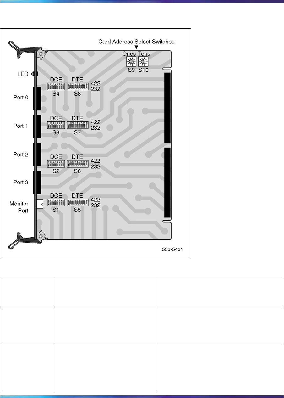
Install the MSDL 97
Figure 40
MSDL card layout
Table 28
MSDL switch settings
Port 0—SW4 Port 0—SW8
RS-232-D o
ff o
ff o
ff o
ff o
ff o
ff o
ff o
ff o
ff o
ff o
ff o
ff o
ff o
ff o
ff o
ff o
ff o
ff
RS-422-A DTE o
ff o
ff o
ff o
ff o
ff o
ff o
ff o
ff o
no
no
no
no
no
no
no
no
no
n
RS-422-A DCE o
no
no
no
no
no
no
no
no
ff o
ff o
ff o
ff o
ff o
ff o
ff o
ff o
ff o
ff
Port 1—SW3 Port 1—SW7
RS-232-D o
ff o
ff o
ff o
ff o
ff o
ff o
ff o
ff o
ff o
ff o
ff o
ff o
ff o
ff o
ff o
ff o
ff o
ff
RS-422-A DTE o
ff o
ff o
ff o
ff o
ff o
ff o
ff o
ff o
no
no
no
no
no
no
no
no
no
n
Nortel Communication Server 1000
ISDN Primary Rate Interface Installation and Commissioning
NN43001-301 02.03 Standard
Release 5.5 7 December 2007
Copyright © 2003-2007, Nortel Networks
.

98 MSDL installation for all systems
RS-422-A DCE o
no
no
no
no
no
no
no
no
ff o
ff o
ff o
ff o
ff o
ff o
ff o
ff o
ff o
ff
Port 2—SW2 Port 2—SW6
RS-232-D o
ff o
ff o
ff o
ff o
ff o
ff o
ff o
ff o
ff o
ff o
ff o
ff o
ff o
ff o
ff o
ff o
ff o
ff
RS-422-A DTE o
ff o
ff o
ff o
ff o
ff o
ff o
ff o
ff o
no
no
no
no
no
no
no
no
no
n
RS-422-A DCE o
no
no
no
no
no
no
no
no
ff o
ff o
ff o
ff o
ff o
ff o
ff o
ff o
ff o
ff
Port 3—SW1 Port 3—SW5
RS-232-D o
ff o
ff o
ff o
ff o
ff o
ff o
ff o
ff o
ff o
ff o
ff o
ff o
ff o
ff o
ff o
ff o
ff o
ff
RS-422-A DTE o
ff o
ff o
ff o
ff o
ff o
ff o
ff o
ff o
no
no
no
no
no
no
no
no
no
n
RS-422-A DCE o
no
no
no
no
no
no
no
no
ff o
ff o
ff o
ff o
ff o
ff o
ff o
ff o
ff o
ff
Replace the MSDL
Replacement procedures for the MSDL card are the same for all Large
Systems. Use Procedure 10 "Replace the MSDL card" (page 98) below.
Procedure 10
Replace the MSDL card
Step Action
1Disable the MSDL card in LD 96.
2Disconnect MSDL to PRI cables.
3Remove the faulty MSDL card.
4Unpack and inspect the new MSDL card.
5Set the MSDL switch settings to correspond to Table 28 "MSDL
switch settings" (page 97) and Figure 40 "MSDL card layout" (page
97).
6Insert the new MSDL card into the selected card slot of the module
following the card guides.
7Observe the red LED on the MSDL faceplate. If it turns on, flashes
three times, and stays on continuously, the MSDL is operating
correctly but is not yet enabled.
If the LED turns on and stays on continuously without flashing
three times, the card can be defective. Go to step 11.
Nortel Communication Server 1000
ISDN Primary Rate Interface Installation and Commissioning
NN43001-301 02.03 Standard
Release 5.5 7 December 2007
Copyright © 2003-2007, Nortel Networks
.

Replace the MSDL 99
8Connect the appropriate cable between the NT6D80 and the PRI
card MSDL interface.
9Enable the MSDL card in LD 96.
10 Unplug the MSDL card and reinsert it. If the red LED still does
not flash three times, leave the card installed for approximately 10
minutes to allow the card to be initialized.
11 After 10 minutes unplug the card and reinsert it. If the red LED does
not flash three times, the card is defective and must be replaced.
—End—
Nortel Communication Server 1000
ISDN Primary Rate Interface Installation and Commissioning
NN43001-301 02.03 Standard
Release 5.5 7 December 2007
Copyright © 2003-2007, Nortel Networks
.

100 MSDL installation for all systems
Nortel Communication Server 1000
ISDN Primary Rate Interface Installation and Commissioning
NN43001-301 02.03 Standard
Release 5.5 7 December 2007
Copyright © 2003-2007, Nortel Networks
.

101
NT8D72 and QPC720 PRI card
installation
Contents The section contains information on the following topics:
"Introduction" (page 101)
"PRI circuit pack locations" (page 101)
"Cable requirements" (page 102)
"Switch settings" (page 120)
"Install NT8D72 and QPC720 PRI cards on Large Systems" (page 123)
"Remove NT8D72 and QPC720 PRI cards from Large Systems" (page 124)
"Install an additional network shelf" (page 125)
Introduction This chapter contains information on how to install the 2.0 Mb NT8D72 and
the 1.5 Mb QPC720 PRI cards on all Large Systems.
Information on how to install the dual-port cards NT5D97 and NT5D12 is
contained in this document.
PRI circuit pack locations
The PRI circuit pack occupies two adjacent slots on a shelf. As many as
five circuit packs can be plugged into an empty Network shelf, along with a
Power Converter circuit pack. Specific locations will depend on available
space.
Note 1: Due to physical width, Bus Terminating Units (BTUs) and PRIs
cannot fit next to each other on a shelf.
Nortel Communication Server 1000
ISDN Primary Rate Interface Installation and Commissioning
NN43001-301 02.03 Standard
Release 5.5 7 December 2007
Copyright © 2003-2007, Nortel Networks
.

102 NT8D72 and QPC720 PRI card installation
Note 2: This chapter includes instructions for installing an additional
network shelf on a system (when no vacant Network slots are available
to install PRI packs, additional network shelves can replace Intelligent
Peripheral Equipment shelves located on the rear of the Common
Equipment or Disk shelves). Refer to "Install an additional network
shelf" (page 125).
Cable requirements
Shielded 22 AWG (0.644 mm) cables are recommended for connecting
the PRI to the crossconnect point. This cable consists of two twisted-pair
conductors.
The transmit and the receive pairs must be enclosed in a polyvinyl jacket.
This type of cable is commonly referred to as "6-conductor" cable. The
cable should be grounded at the crossconnect point.
In addition to twisted-pair conductors, 75-ohm coaxial cable can also be
used to provide connection to the office repeater or line terminating unit
(LTU).
For manufacture cables of lengths different than those of the standard
cables provided, see "Nonstandard cables" on "Nonstandard cables" (page
295) of this practice.
For the 2.0 Mb NT8D72 PRI card, see Figure 41 "NT8D72(Half Group
cabling) on Half and Single Group systems without an echo canceller"
(page 103),Figure 42 "NT8D72 (Half Group cabling) for Half and Single
Group systems, with an echo canceller" (page 104),Figure 43 "NT8D72
(Single Group cabling) for Half and Single Group systems, without an echo
canceller" (page 105), and Figure 44 "NT8D72 (Single Group cabling) for
Half and Single Group systems, with an echo canceller" (page 106) for Half
Group and Single Group cabling arrangements applying to the system; also,
refer to Table 52 "NTBK51AA DCH switches for NT5D97AD" (page 138).
For the 2.0 NT8D72 on a Multi Group arrangement, see Figure 45 "NT8D72
(Multi Group cabling) for Multi Group systems without an echo canceller"
(page 107) and Figure 46 "NT8D72 (Multi Group cabling) for Multi Group
systems with an echo canceller" (page 108); also refer to Table 30 "Cable
for the NT8D72 PRI card for Multi Group systems" (page 116).
For the 1.5 Mb QPC720 PRI card on Half Group and Single Group systems,
see Figure 47 "QPC720 (Half Group cabling) for Multi Group systems
without an echo canceller" (page 109),Figure 48 "QPC720 (Half Group
cabling) for Multi Group systems with an echo canceller" (page 110),Figure
49 "QPC720 (Single Group cabling) for Multi Group systems without an
echo canceller" (page 111), also, refer to Table 31 "Cable for the QPC720
PRI card for Half and Multi Group systems" (page 117). For the QPC720 on
Nortel Communication Server 1000
ISDN Primary Rate Interface Installation and Commissioning
NN43001-301 02.03 Standard
Release 5.5 7 December 2007
Copyright © 2003-2007, Nortel Networks
.
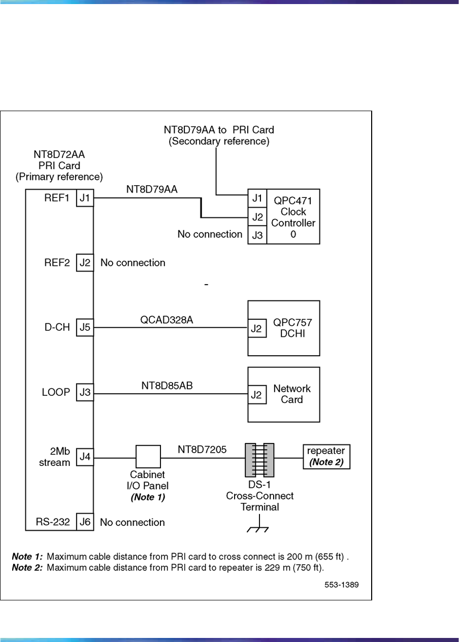
Cable requirements 103
Multi Group systems, see Figure 51 "QPC720 Multi Group cabling without
an echo canceller" (page 113) and Figure 52 "QPC720 Multi Group cabling
with an echo canceller" (page 114); also refer to Table 32 "Cable for the
QPC720 PRI card on Multi Group systems" (page 118).
Figure 41
NT8D72(Half Group cabling) on Half and Single Group systems without an echo canceller
Nortel Communication Server 1000
ISDN Primary Rate Interface Installation and Commissioning
NN43001-301 02.03 Standard
Release 5.5 7 December 2007
Copyright © 2003-2007, Nortel Networks
.

104 NT8D72 and QPC720 PRI card installation
Figure 42
NT8D72 (Half Group cabling) for Half and Single Group systems, with an echo canceller
Nortel Communication Server 1000
ISDN Primary Rate Interface Installation and Commissioning
NN43001-301 02.03 Standard
Release 5.5 7 December 2007
Copyright © 2003-2007, Nortel Networks
.
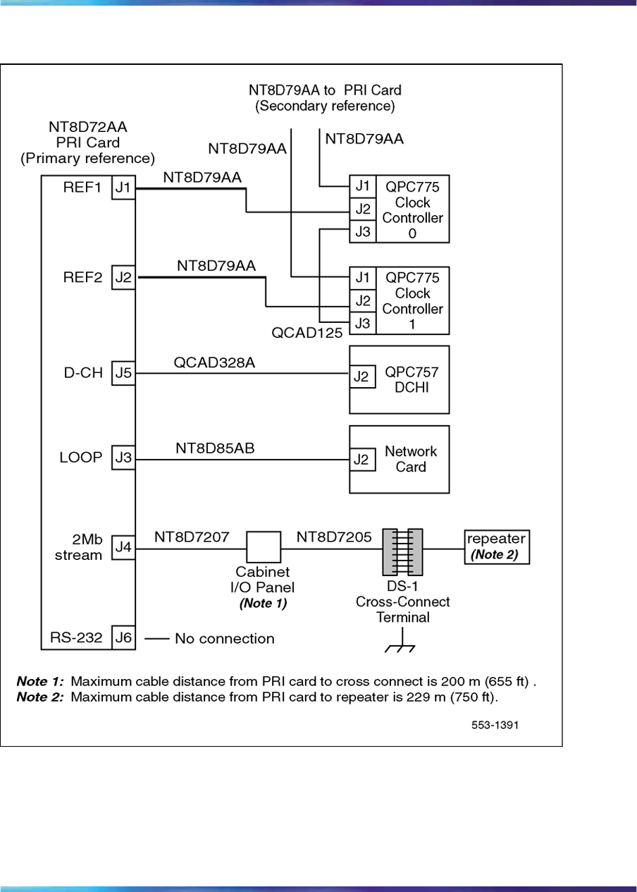
Cable requirements 105
Figure 43
NT8D72 (Single Group cabling) for Half and Single Group systems, without an echo canceller
Nortel Communication Server 1000
ISDN Primary Rate Interface Installation and Commissioning
NN43001-301 02.03 Standard
Release 5.5 7 December 2007
Copyright © 2003-2007, Nortel Networks
.
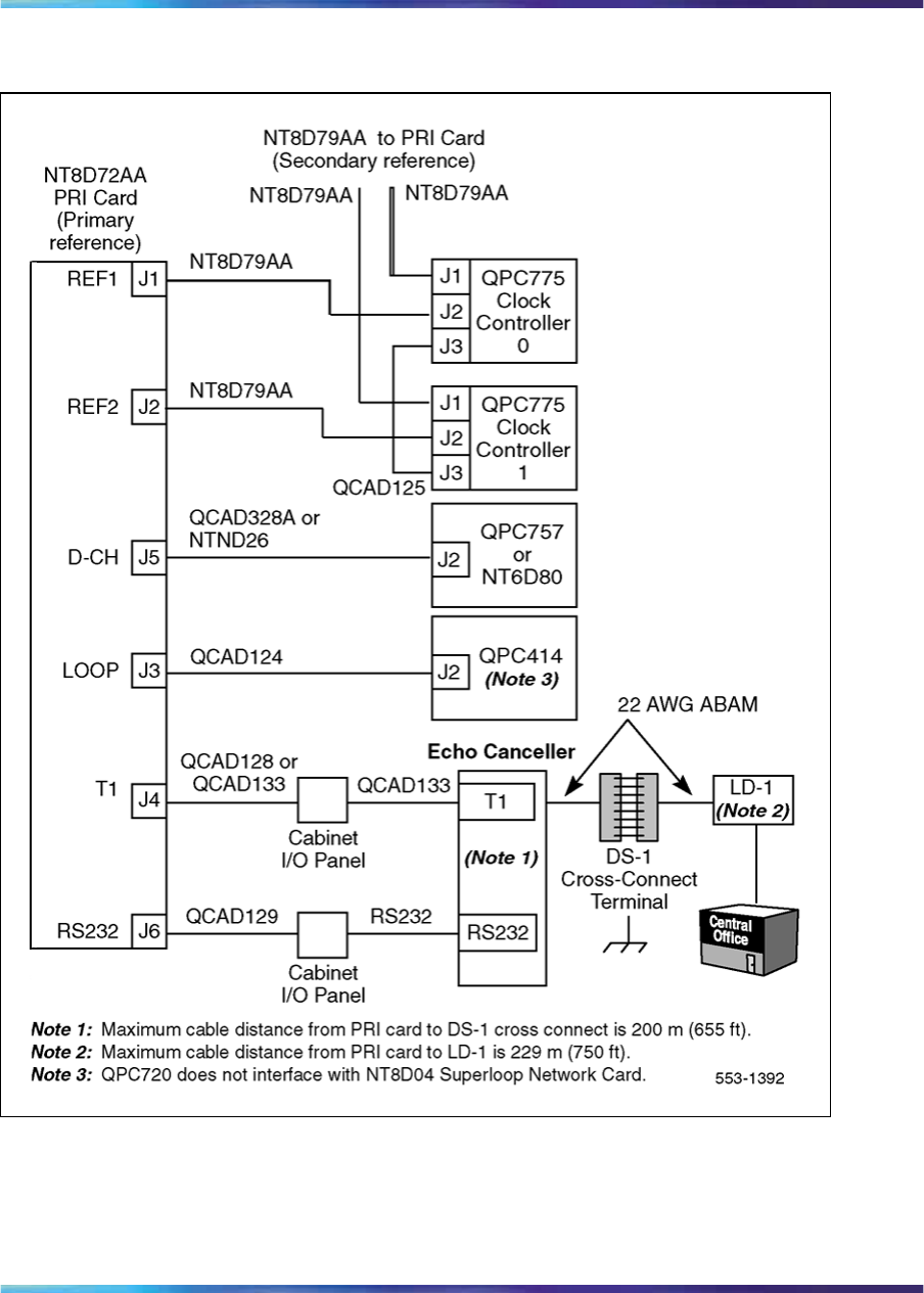
106 NT8D72 and QPC720 PRI card installation
Figure 44
NT8D72 (Single Group cabling) for Half and Single Group systems, with an echo canceller
Nortel Communication Server 1000
ISDN Primary Rate Interface Installation and Commissioning
NN43001-301 02.03 Standard
Release 5.5 7 December 2007
Copyright © 2003-2007, Nortel Networks
.

Cable requirements 107
Figure 45
NT8D72 (Multi Group cabling) for Multi Group systems without an echo canceller
Nortel Communication Server 1000
ISDN Primary Rate Interface Installation and Commissioning
NN43001-301 02.03 Standard
Release 5.5 7 December 2007
Copyright © 2003-2007, Nortel Networks
.

108 NT8D72 and QPC720 PRI card installation
Figure 46
NT8D72 (Multi Group cabling) for Multi Group systems with an echo canceller
Nortel Communication Server 1000
ISDN Primary Rate Interface Installation and Commissioning
NN43001-301 02.03 Standard
Release 5.5 7 December 2007
Copyright © 2003-2007, Nortel Networks
.
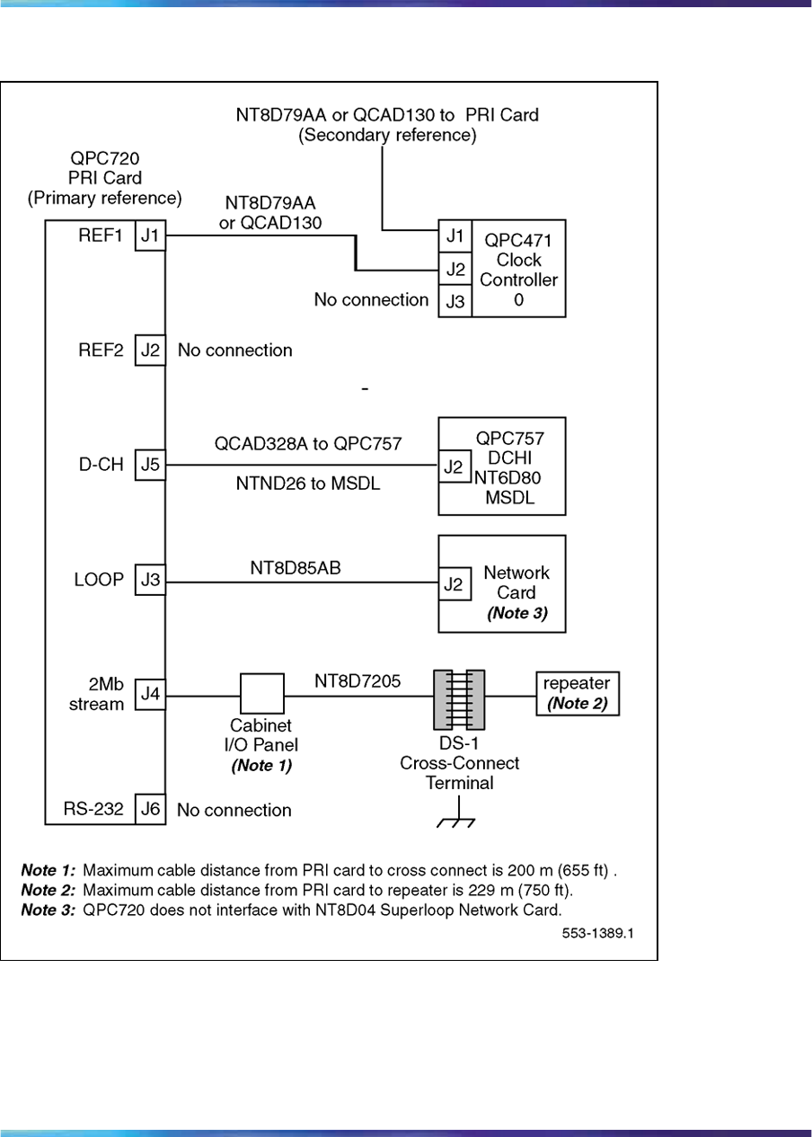
Cable requirements 109
Figure 47
QPC720 (Half Group cabling) for Multi Group systems without an echo canceller
Nortel Communication Server 1000
ISDN Primary Rate Interface Installation and Commissioning
NN43001-301 02.03 Standard
Release 5.5 7 December 2007
Copyright © 2003-2007, Nortel Networks
.
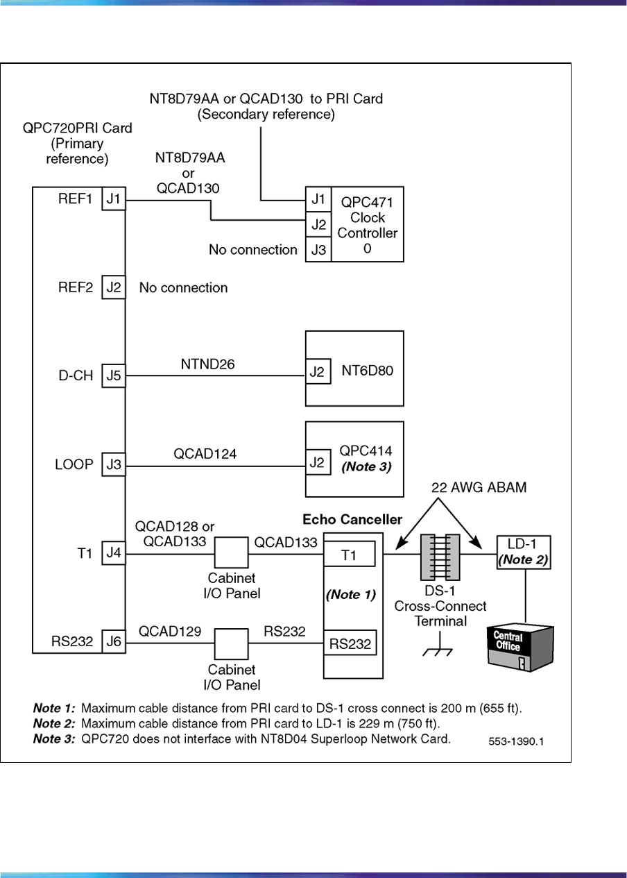
110 NT8D72 and QPC720 PRI card installation
Figure 48
QPC720 (Half Group cabling) for Multi Group systems with an echo canceller
Nortel Communication Server 1000
ISDN Primary Rate Interface Installation and Commissioning
NN43001-301 02.03 Standard
Release 5.5 7 December 2007
Copyright © 2003-2007, Nortel Networks
.
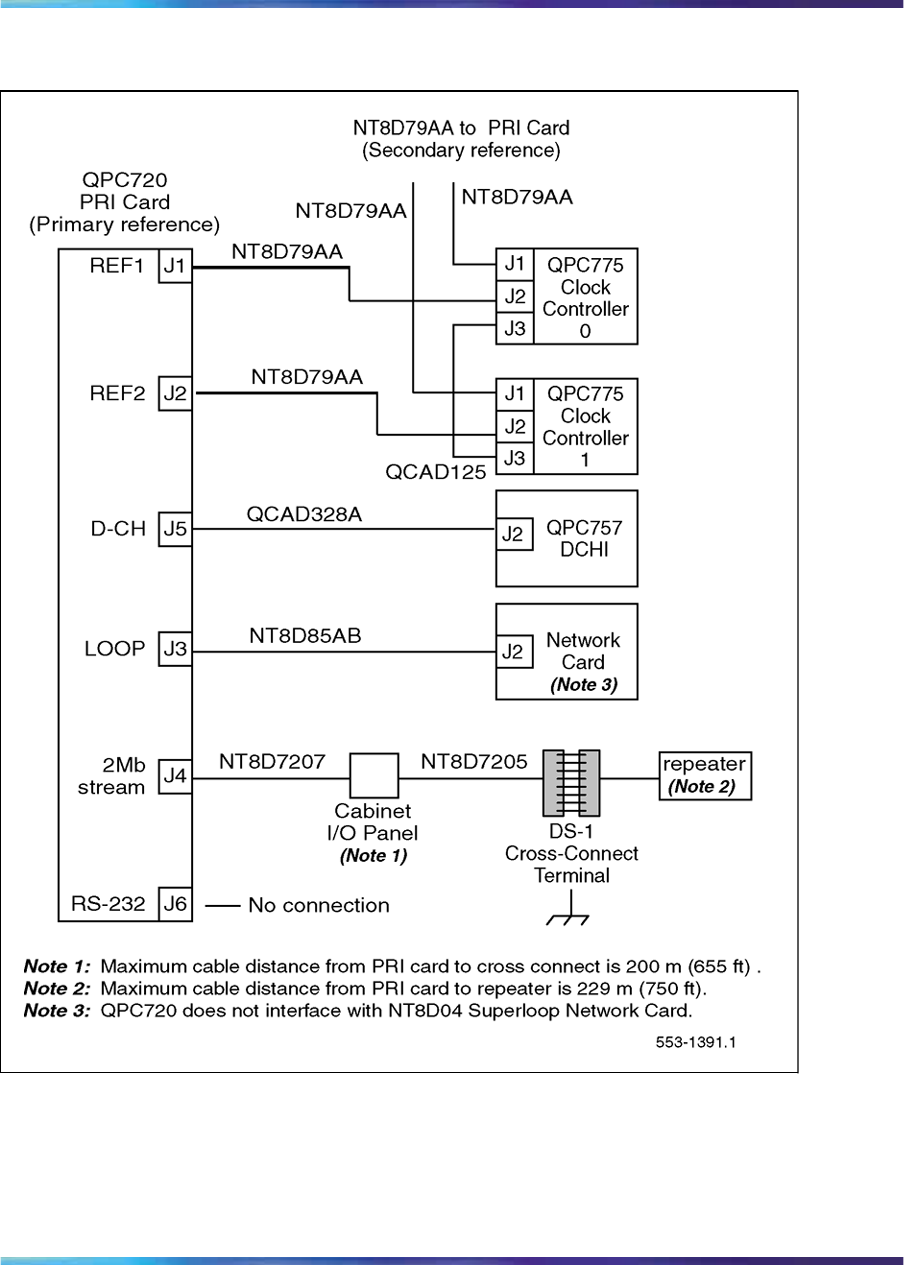
Cable requirements 111
Figure 49
QPC720 (Single Group cabling) for Multi Group systems without an echo canceller
Nortel Communication Server 1000
ISDN Primary Rate Interface Installation and Commissioning
NN43001-301 02.03 Standard
Release 5.5 7 December 2007
Copyright © 2003-2007, Nortel Networks
.

112 NT8D72 and QPC720 PRI card installation
Figure 50
QPC720 (Single Group cabling) for Multi Group systems with an echo canceller
Nortel Communication Server 1000
ISDN Primary Rate Interface Installation and Commissioning
NN43001-301 02.03 Standard
Release 5.5 7 December 2007
Copyright © 2003-2007, Nortel Networks
.
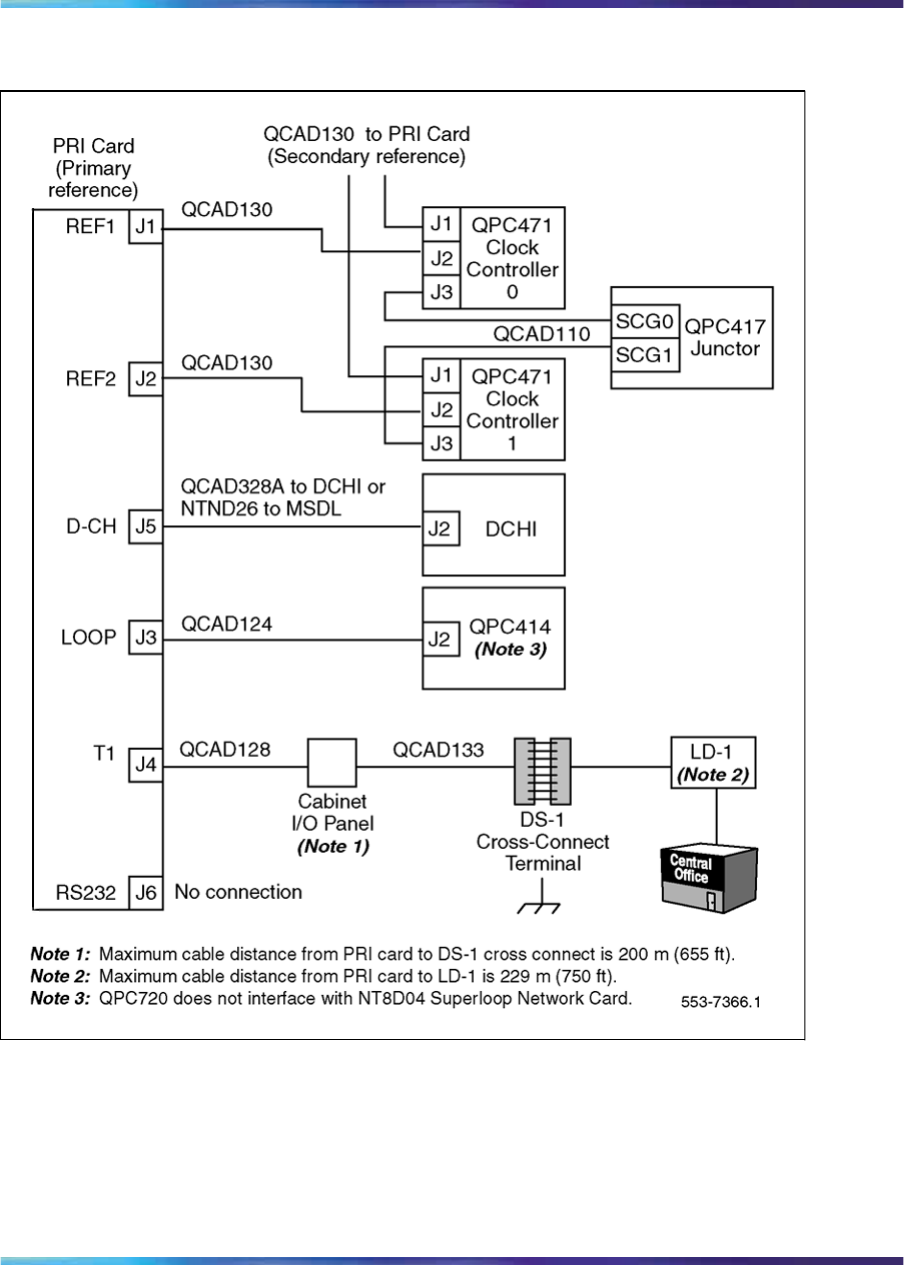
Cable requirements 113
Figure 51
QPC720 Multi Group cabling without an echo canceller
Nortel Communication Server 1000
ISDN Primary Rate Interface Installation and Commissioning
NN43001-301 02.03 Standard
Release 5.5 7 December 2007
Copyright © 2003-2007, Nortel Networks
.
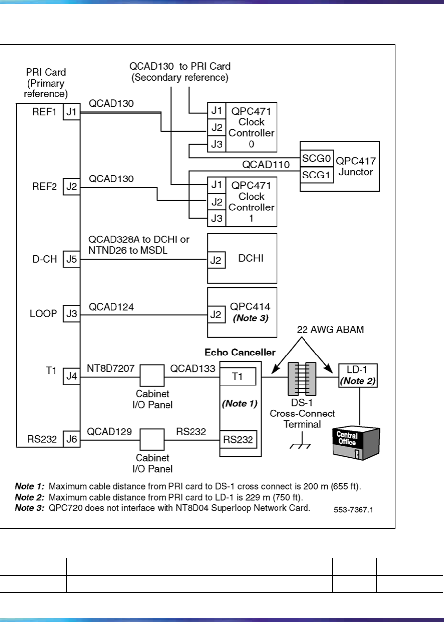
114 NT8D72 and QPC720 PRI card installation
Figure 52
QPC720 Multi Group cabling with an echo canceller
Table 29
Cable for the NT8D72 PRI card for Half and Single Group systems
Cable From Des Con To Des Con To
NTND26 PRI card J5 MSDL
Nortel Communication Server 1000
ISDN Primary Rate Interface Installation and Commissioning
NN43001-301 02.03 Standard
Release 5.5 7 December 2007
Copyright © 2003-2007, Nortel Networks
.

Cable requirements 115
Cable From Des Con To Des Con To
NT8D79AA PRI card J1 Clock contro
ller CC-0 J2 Only when
primary
clock source.
NT8D79AA PRI card J1 Clock contro
ller CC-0 J1 Only when
secondary
clock source.
For single-group only
NT8D79AA PRI card J2 Clock contro
ller CC-1 J2 Only when
primary
clock source.
NT8D79AA PRI card J2 Clock contro
ller CC-1 J1 Only when
secondary
clock source.
QCAD125 Clock contro
ller CC-0 J3 Clock contro
ller CC-1 J3 Clock Contro
ller back-up.
NT8D85AB PRI card J3 Network Run directly
to Network
pack.
QCAD328A PRI card J2 DCHI J2 Run directly
to DCHI
card.
NTND26 PRI card J5 MSDL
NT8D7207 PRI card J4 I/O Panel
RS-232 I/O Panel Echo cancell
er
RS-232 PRI card J6 Echo cancell
er
NT8D7205 I/O Panel cross conne
ct Run via
cabinet I/O
panel to cro
ssconnect
terminal from
switch.
Note: No additional cabling is required for multiple PRIs. The D-channel
is associated through software in LD 17 (prompt PRI).
Nortel Communication Server 1000
ISDN Primary Rate Interface Installation and Commissioning
NN43001-301 02.03 Standard
Release 5.5 7 December 2007
Copyright © 2003-2007, Nortel Networks
.
116 NT8D72 and QPC720 PRI card installation
Table 30
Cable for the NT8D72 PRI card for Multi Group systems
Cable From Des. Con. To Des. Con. Notes
QCAD130 PRI card J1 Clock contro
ller CC-0 1
QCAD130 PRI card J1 Clock contro
ller CC-0 2
QCAD130 PRI card J2 Clock contro
ller CC-1 1
QCAD130 PRI card J2 Clock contro
ller CC-1 2
QCAD110 Clock contro
ller CC-0 J3 Junctor
board JCTR J11 3
QCAD110 Clock contro
ller CC-1 J3 Junctor
board JCTR J12
QCAD124 PRI card J3 Network 4
QCAD328A PRI card J5 DCHI card J2 5
NTND26 PRI card J5 MSDL
QCAD128 PRI card J4 I/O Panel 6
QCAD133 I/O Panel Patch Panel 6
QCAD129 PRI card J6 I/O Panel 6
RS-232 I/O Panel Echo Cance
ller
RS-232 PRI card J6 Echo Cance
ller
7
Note 1: Only when primary clock source.
Note 2: Only when secondary clock source.
Note 3: multigroup junctor board connection.
Note 4: Run to connector on network pack.
Note 5: Run directly to DCHI card.
Note 6: Run by means of cabinet I/O panel to CSU, echo canceller, or cross connect terminal.
Note 7: Run by means of cabinet I/O panel to crossconnect terminal or echo canceller from non
shielded system.
Note 8: No additional cabling is required for multiple PRIs. The D-channel is associated through
software in LD17, prompt PRI.
Nortel Communication Server 1000
ISDN Primary Rate Interface Installation and Commissioning
NN43001-301 02.03 Standard
Release 5.5 7 December 2007
Copyright © 2003-2007, Nortel Networks
.
Cable requirements 117
Cable From Des. Con. To Des. Con. Notes
QCAD133 PRI card J4 Patch Panel 7
RS-232 PRI card J6 Echo Cance
ller
7
Note 1: Only when primary clock source.
Note 2: Only when secondary clock source.
Note 3: multigroup junctor board connection.
Note 4: Run to connector on network pack.
Note 5: Run directly to DCHI card.
Note 6: Run by means of cabinet I/O panel to CSU, echo canceller, or cross connect terminal.
Note 7: Run by means of cabinet I/O panel to crossconnect terminal or echo canceller from non
shielded system.
Note 8: No additional cabling is required for multiple PRIs. The D-channel is associated through
software in LD17, prompt PRI.
Table 31
Cable for the QPC720 PRI card for Half and Multi Group systems
Cable From Des. Con. To Des. Con. Comments
For half group only
QCAD130
NT8D79xx QPC720 J1 QPC471/
QPC775 CC-0 J2 Only when
primary clock
source.
QCAD130
NT8D79xx QPC720 J1 QPC471/
QPC775 CC-0 J1 Only when
secondary clock
source.
NTND26 QPC720 J5 NT6D80
For single group only
QCAD130
NT8D79xx QPC720 J2 QPC471/
QPC775 CC-1 J2 Only when
primary clock
source.
QCAD130
NT8D79xx QPC720 J2 QPC471/
QPC775 CC-1 J1 Only when
secondary clock
source.
QCAD125
NT8D75xx QPC471/
QPC775 CC-0 J3 QPC471/
QPC775 CC-1 J3 Clock controller
back-up.
Nortel Communication Server 1000
ISDN Primary Rate Interface Installation and Commissioning
NN43001-301 02.03 Standard
Release 5.5 7 December 2007
Copyright © 2003-2007, Nortel Networks
.
118 NT8D72 and QPC720 PRI card installation
Cable From Des. Con. To Des. Con. Comments
QCAD124
NT8D85xx QPC720 J3 Network Run directly to
network card.
QCAD328A QPC720 J5 QPC757 J2 Run directly to
DCHI card.
NTND26 QPC720 J5 NT6D80
QCAD133 I/O Panel Patch panel Run via cabinet
I/O panel to
CSU, Echo
Canceller, or
cross connect
terminal.
QCAD129 QPC720 J6 I/O Panel
RS-232 I/O Panel Echo Canc
eller
RS-232 QPC720 J6 Echo Canc
eller
QCAD133
NT8D83xx QPC720 J4 Patch panel Run via cabinet
I/O panel to
crossconnect
terminal or Echo
Canceller from
non-shielded
system.
Table 32
Cable for the QPC720 PRI card on Multi Group systems
Cable From Des. Con. To Des. Con. Notes
QCAD130
NT8D79xx QPC720 J1 QPC47
1
QCP77
5
CC-0 Only when
primary clock
source
QCAD130
NT8D79xx QPC720 J1 QPC47
1
QCP77
5
CC-0 Only when
secondary clock
source
QCAD130
NT8D79xx QPC720 J2 QPC47
1
QCP77
5
CC-1 Only when
primary clock
source
Nortel Communication Server 1000
ISDN Primary Rate Interface Installation and Commissioning
NN43001-301 02.03 Standard
Release 5.5 7 December 2007
Copyright © 2003-2007, Nortel Networks
.

Cable requirements 119
Cable From Des. Con. To Des. Con. Notes
QCAD130
NT8D79xx QPC720 J2 QPC47
1
QCP77
5
CC-1 Only when
secondary clock
source
QCAD110
NT8D74xx QPC471
QCP775 CC-0 J3 QPC417 JCTR J11 multigroup
junctor board
connection
QCAD110
NT8D74xx QPC471
QCP775 CC-1 J3 QPC417 JCTR J12
QCAD124
NT8D85xx QPC720 J3 Network Run to connec
tor on network
pack
QCAD328 QPC720 J5 QPC757 J2 Run directly to
DCHI card
NTND26 QPC720 J5 NT6D80
QCAD128
NT8D83xx QPC720 J4 I/O
Panel Run via cabinet
I/O panel to
CSU, Echo
Canceller, or
crossconnect
terminal
QCAD133
NT8D83xx I/O
Panel Patch
Panel Run via cabinet
I/O panel to
CSU, Echo
Canceller, or
crossconnect
terminal
QCAD129
NT9J93xx QPC720 J6 I/O
Panel Run via cabinet
I/O panel to
CSU, Echo
Canceller, or
crossconnect
terminal
RS-232 I/OPanel Echo
Canceller
RS-232 QPC720 J6 Echo
Canceller Run via cabinet
I/O panel to
Echo Canceller
or crossconnect
terminal from
non-shielded
system
Nortel Communication Server 1000
ISDN Primary Rate Interface Installation and Commissioning
NN43001-301 02.03 Standard
Release 5.5 7 December 2007
Copyright © 2003-2007, Nortel Networks
.

120 NT8D72 and QPC720 PRI card installation
Cable From Des. Con. To Des. Con. Notes
QCAD133
NT8D83xx QPC720 J4 Patch Panel Run via cabinet
I/O panel to
Echo Canceller
or crossconnect
terminal from
non-shielded
system
RS-232 QPC720 J6 Echo
Canceller Run via cabinet
I/O panel to
Echo Canceller
or crossconnect
terminal from
non-shielded
system
Switch settings
Figure 53 "NT8D72AA, NT8D72AB, NT8D72BA PRI DIP switch settings
for Large Systems" (page 121) shows the NT8D72AA, NT8D72AB, and
NT8D72BA PRI DIP switch settings for Large Systems. Figure 54 "QPC720
switch settings for Half and Single Group systems" (page 122) shows the
QPC720 PRI switch settings for Large Systems.
Table 33 "NT8D72 and QPC720 PRI transmission equalization switch
settings for Large Systems" (page 122) indicates the Transmission
equalization switch settings for the NT8D72 and QPC720 PRI cards for
Large Systems.
Nortel Communication Server 1000
ISDN Primary Rate Interface Installation and Commissioning
NN43001-301 02.03 Standard
Release 5.5 7 December 2007
Copyright © 2003-2007, Nortel Networks
.
Switch settings 121
Figure 53
NT8D72AA, NT8D72AB, NT8D72BA PRI DIP switch settings for Large Systems
Note: For EuroISDN applications, use the default setting (120 ohms).
Nortel Communication Server 1000
ISDN Primary Rate Interface Installation and Commissioning
NN43001-301 02.03 Standard
Release 5.5 7 December 2007
Copyright © 2003-2007, Nortel Networks
.

122 NT8D72 and QPC720 PRI card installation
Figure 54
QPC720 switch settings for Half and Single Group systems
Table 33
NT8D72 and QPC720 PRI transmission equalization switch settings for Large Systems
Switch S2 settings To repeater facility To crossconnect point
5on 0 - 45 m
(0 - 150 ft) 0 - 30 m
(0 - 100 ft)
2, 4, 6 on 46 - 135 m
(151 - 450 ft) 31 - 100 m
(101 - 355 ft)
1, 3, 7 on 136 - 225 m
(451 - 750 ft) 101 - 200 m
(356 - 655 ft)
Switch 3 options for PRI with ESF
SW3-1 on = extended superframe format (ESF)
off = superframe format (SF)
Note 1: All positions on S2 (location B22) are OFF except as shown under the column labeled
"Switch S2 settings." The 8-pole SW3 (location E37) positions are OFF except for SW3-1 as shown
for "Switch 3 option for DTI with ESF."
Note 2: For D2, D3, or D4 framing formats (superframe formats), set all SW3 options to OFF.
Note 3: For the DTI with ESF option, you must set the framing format as ESF with the DLOP prompt
in LD17 before you set SW3-1 on the card.
Nortel Communication Server 1000
ISDN Primary Rate Interface Installation and Commissioning
NN43001-301 02.03 Standard
Release 5.5 7 December 2007
Copyright © 2003-2007, Nortel Networks
.
Install NT8D72 and QPC720 PRI cards on Large Systems 123
Install NT8D72 and QPC720 PRI cards on Large Systems
Use Procedure 11 "Install the NT8D72 and QPC720 PRI on Large Systems"
(page 123) to install the NT8D72 and QPC720 PRI cards on Large Systems.
Procedure 11
Install the NT8D72 and QPC720 PRI on Large Systems
Step Action
1Determine the cabinet and shelf location of the circuit card to be
installed. The following slots can be used if they are not required
for other cards.
Table 34
Shelf and slot location of NT8D72 and QPC720 for Half Group and Single Group systems
System Shelf Slot
Half Group,
Single Group NT6D39 CPU/NET 3–8 Note 1
18 Note 3
NT8D35 DTI Exp Cube 2–3 Note 1
5–14 Note 1
NT8D47 RPE Cube 1, 11, 12
Multi Group Core 0-3
Network Module 5–10,
13–14
Note 1: DTI/PRI packs require two slots. The slot indicated is the maximum slot that the pack
resides in. For example, the slot 14 pack uses slots 13 and 14.
Note 2: The DTI/PRI pack cannot be installed in slot 11. The pack would come in contact with the
BTU installed between slots 11 and 12.
Note 3: Slot 18 is only available on CPU shelf, which has no MDU/FDU.
Note 4: DTI/PRI pack could reside in slots 10 and 11, but cannot reside in slots 11 and 12 because
of powering restrictions.
2Unpack and inspect the PRI cards.
3Set the option switches on the PRI circuit cards.
4Install the PRI circuit card in the assigned shelf and slot.
5Install the network circuit card (if no network loop connection is
available).
6If required, install I/O adapters in the I/O panel.
Nortel Communication Server 1000
ISDN Primary Rate Interface Installation and Commissioning
NN43001-301 02.03 Standard
Release 5.5 7 December 2007
Copyright © 2003-2007, Nortel Networks
.

124 NT8D72 and QPC720 PRI card installation
7Run and connect the PRI cables.
8If required, install connecting blocks at MDF or wall-mounted
crossconnect terminal.
9If required, designate connecting blocks at MDF or wall-mounted
crossconnect terminal.
10 If required, install CSU or Echo Canceller.
11 Crossconnect PRI circuits.
12 Add related office data into system memory. Refer to the work order.
13 Run PRI verification tests.
—End—
Remove NT8D72 and QPC720 PRI cards from Large Systems
UseProcedure 12 " " (page 124) to remove the NT8D72 and QPC720 PRI
cards from Large Systems.
Procedure 12
Step Action
1Disable the D-channel in LD 96.
2Disable Network Loop using LD 60. The command is DISL x.
3Remove the data from memory if the circuit card is being completely
removed, not replaced.
4Determine the location of the circuit cards to be removed.
5Remove cross connections at MDF to wall-mounted crossconnect
terminal.
6Disconnect PRI cables at Echo Canceller and at carrier interface (for
example, Office Repeater and NCTE equipment).
7Tag and disconnect cables from card. Rearrange Clock Controller
card cables if required. This will affect call processing on DTI/PRI
loops.
8Remove PRI and network circuit cards. If the other circuit of a dual
network card is in use, DO NOT remove the network card.
9Pack and store circuit card.
Nortel Communication Server 1000
ISDN Primary Rate Interface Installation and Commissioning
NN43001-301 02.03 Standard
Release 5.5 7 December 2007
Copyright © 2003-2007, Nortel Networks
.

Install an additional network shelf 125
—End—
Install an additional network shelf
Use Procedure 13 "Install an additional network shelf on Half Group and
Single Group systems" (page 125) to install an additional network shelf,
when additional shelf space is required for PRI cards on Half Group and
Single Group systems. A QUD15 cooling unit is required for each additional
shelf installed.
CAUTION
Do not place the circuit packs in the shelf until Step 7 is completed.
Procedure 13
Install an additional network shelf on Half Group and Single Group systems
Step Action
1Determine the cabinet and shelf location of the Network shelf to
be installed.
2Unpack and inspect the shelf.
3Remove the existing left or right rear Intelligent Peripheral Equipment
(IPE) shelf (if required).
4Install the additional Network shelf in the IPE (Step 3) location.
5Install a QUD15 cooling unit directly below the Network shelf and
secure with four mounting screws.
6Install and connect the QCAD172A power cable to the added
QUD15 cooling unit as follows:
•If the added QUD15 is located below the left Network shelf,
unplug the C11 connector from the QCAD111 power harness
that connects to the existing left side QUD15.
•If the added QUD15 is located below the right Network shelf,
unplug the C21 connector from the QCAD111 power harness
instead of the C11.
7Plug the C11 or C21 connector into the single-ended connector of
the QCAD172A power cable.
Nortel Communication Server 1000
ISDN Primary Rate Interface Installation and Commissioning
NN43001-301 02.03 Standard
Release 5.5 7 December 2007
Copyright © 2003-2007, Nortel Networks
.

126 NT8D72 and QPC720 PRI card installation
8Plug one of the two connectors at the other end of the C11 or C21
connector that was removed.
9Plug the remaining connector of the QCAD172A power cable into
the added QUD15.
10 Adjust the QCAD111 power wiring harness, untie and then connect:
•the C17 power connection cable to the right rear Network shelf
•the C19 power connection cable to the left rear Network shelf
11 Install PRI trunks and enter related shelf and PRI office data into
switch memory.
—End—
Nortel Communication Server 1000
ISDN Primary Rate Interface Installation and Commissioning
NN43001-301 02.03 Standard
Release 5.5 7 December 2007
Copyright © 2003-2007, Nortel Networks
.

127
NT5D97 Dual-port DTI2/PRI2 installation
and removal
Contents The section contains information on the following topics:
"Introduction" (page 127)
"NT5D97 circuit card locations" (page 127)
"Port definitions" (page 128)
"Case Scenarios for replacing a digital trunk NT8D72BA, QPC536E, or
NTCK43 by a DDP2 card" (page 128)
"NT5D97AA/AB DIP switch settings" (page 129)
"Install the NT5D97 DDP2" (page 139)
"Remove the NT5D97 DDP2" (page 140)
"Configure the NT5D97 DDP2" (page 141)
Introduction This section contains information required to install the NT5D97 Dual-port
DTI2/PRI2 (DDP2) card on Large Systems.
For installation and removal procedures for the NTBK51AA Downloadable
D-channel daughterboard, prefer to the section "NTBK51 DDCH installation
and removal" (page 91).
NT5D97 circuit card locations
Each NT5D97 card requires one slot on a shelf. NT5D97 cards can be
placed in any card slot in the network bus.
Nortel Communication Server 1000
ISDN Primary Rate Interface Installation and Commissioning
NN43001-301 02.03 Standard
Release 5.5 7 December 2007
Copyright © 2003-2007, Nortel Networks
.
128 NT5D97 Dual-port DTI2/PRI2 installation and removal
Port definitions
Since the NT5D97 card is a dual-card, it equips two ports; these ports can
be defined in the following combinations:
Table 35
NT5D97AA/AB loops configuration
Loop 0
not configured DTI2 PRI2
not configured V V V
DTI2 V V V
Loop
1
PRI2 V V V
Table 36
NT5D97AD loops configuration
Loop 0
not configured DTI2 PRI2 DDCS
not configured V V V V
DTI2 V V V V
PRI2 V V V X
Loop 1
DDCS V V X V
Note: Each loop DPNSS can be defined in Normal or Extended
addressing mode.
Case Scenarios for replacing a digital trunk NT8D72BA, QPC536E,
or NTCK43 by a DDP2 card
The following discussion describes possible scenarios when replacing a
digital trunk NT8D72BA PRI2 card or QPC536E DTI2 card or NTCK43 Dual
PRI card configuration with a NT5D97 DDP2 card configuration.
Case 1 - The two ports of a QPC414 network card are connected to two
digital trunks.
In this case, the QPC414 and the two digital trunks are replaced by a single
DDP2 card, which is plugged into the network shelf in the QPC414 slot.
Case 2 - One port of the QPC414 card is connected to a digital trunk, and
the second is connected to a peripheral buffer. Both cards are in a network
loop location.
In this case, the QPC414 should not be removed. The digital trunk is
removed and the DDP2 card is plugged into one of the two empty slots.
Nortel Communication Server 1000
ISDN Primary Rate Interface Installation and Commissioning
NN43001-301 02.03 Standard
Release 5.5 7 December 2007
Copyright © 2003-2007, Nortel Networks
.

NT5D97AA/AB DIP switch settings 129
Case 3 - The network shelf is full, one port of a QPC414 network card is
connected to a digital trunk, and the second is connected to a peripheral
buffer. This arrangement is repeated for another QPC414. The digital trunks
are located in a shelf that provides only power.
In this case, the peripheral buffers will have to be reassigned, so that each
pair of buffers will use both ports of the same QPC414 card. The other
QPC414 card can then be replaced by the NT5D97 DDP2.
Note: If an NT8D72BA/NTCK43 card is being replaced by a DDP2
card, the D-channel Handler can be reconnected to the DDP2 card, or
removed if an onboard NTBK51DDCH card is used. Also, DIP Switches
in the NT5D97 must be set properly before insertion. NT5D97 has a
different DIP Switch setting from NTCK43AB. Refer to "NT5D97AA/AB
DIP switch settings" (page 129) for DIP switch setting).
NT5D97AA/AB DIP switch settings
The NT5D97 DDP2 card is equipped with 6x2 sets of DIP switches for
trunk parameters settings for port0 and port1 respectively. Additionally,
the DDP2 card is equipped with one set of four DIP switches for the Ring
Ground setting. The NT5D97AA/AB has one set of eight DIP switches and
NT5D97AD has two sets of ten DIP switches for the D-channel Handler
parameters setting.
The DIP switches are used for the setting of default values of certain
parameters. Firmware reads the general purpose switches, which sets the
default values accordingly.
Table 37
DIP switch settings for NT5D97AA/AB
Card Trunks
0 and 1 Port 0 Port 1 Trunk 0 Trunk 1
ENB/DSB
mounted on the face plate S1
Ring Ground S2
MSDL S3
Tx Mode S4 S10
S5 S11
S6 S12LBO Setting
S7 S13
Receiver Interface S8 S14
General Purpose S9 S15
Nortel Communication Server 1000
ISDN Primary Rate Interface Installation and Commissioning
NN43001-301 02.03 Standard
Release 5.5 7 December 2007
Copyright © 2003-2007, Nortel Networks
.
130 NT5D97 Dual-port DTI2/PRI2 installation and removal
Figure 55
DIP switches for NT5D97AA/AB
The following parameters are set by DIP switches. The boldface font shows
the factory setup.
Nortel Communication Server 1000
ISDN Primary Rate Interface Installation and Commissioning
NN43001-301 02.03 Standard
Release 5.5 7 December 2007
Copyright © 2003-2007, Nortel Networks
.
NT5D97AA/AB DIP switch settings 131
Trunk interface switches for NT5D97AA/AB
Impedance level and unit mode
The S9/S15 switch selects the impedance level and loop operation mode on
DEI2 OR PRI2. Refer to Table 38 "Impedance level and loop mode switch
settings" (page 131).
Table 38
Impedance level and loop mode switch settings
Switch Description S9/S15 Switch Setting
1Impedance level OFF - 120 ohm
ON - 75 ohm
2Spare X
3Spare X
4Unit mode OFF - Loop operates in the DTI2 mode
ON - Loop operates in the PRI2 mode
Transmission mode
A per-trunk switch (S4/S10) provides a selection of the digital trunk interface
type. Refer to Table 39 "Impedance level and loop mode switch settings"
(page 131).
Table 39
Impedance level and loop mode switch settings
Description S4/S10 switch settings
E1 OFF
Not used
Line build out
A per-trunk set of three switches (S5/S11, S6/S12 and S7/S13) provides
the dB value for the line build out. Refer to Table 40 "Trunk interface line
build out switch settings" (page 131).
Note: Do not change this setup.
Table 40
Trunk interface line build out switch settings
Description Switch setting
S5/S11 S6/S12 S7/S13
0dB OFF OFF OFF
Nortel Communication Server 1000
ISDN Primary Rate Interface Installation and Commissioning
NN43001-301 02.03 Standard
Release 5.5 7 December 2007
Copyright © 2003-2007, Nortel Networks
.
132 NT5D97 Dual-port DTI2/PRI2 installation and removal
Receiver impedance
A per-trunk set of four DIP switches (S8/S14 provides selection between
75 or 120 ohm values. Refer toTable 41 "Trunk interface impedance switch
settings" (page 132).
Table 41
Trunk interface impedance switch settings
Description S8/S14 switch setting
75 ohm OFF OFF ON OFF
120 ohm OFF OFF OFF ON
Ring ground switches for NT5D97AA/AB
A set of four DIP switches (S2) selects which Ring lines are connected to
the ground. Refer to Table 48 "LBO switches for NT5D97AD" (page 136).
Table 42
Ring ground switch settings
Switch Description S2 switch settings
1Trunk 0 Transit OFF-Ring line is not grounded
ON- Ring line is grounded
2Trunk 0 Receive OFF-Ring line is not grounded
ON- Ring line is grounded
3Trunk 1 Transmit OFF-Ring line is not grounded
ON- Ring line is grounded
4Trunk 1 Receive OFF-Ring line is not grounded
ON- Ring line is grounded
DCH Address select switch for NTBK51AA daughter board for
NT5D97AA/AB
In case of an onboard NTBK51AA D-channel daughterboard, a set of four
switches (S3) provide the daughterboard address. Refer to Table 50 "Trunk
1 switches" (page 137).
Note: Switch 8 of S3 (S3-8) does not require a switch setting to
select between the onboard NTBK51AA D-channel daughterboard
and an external DCHI/MSDL. The NT5D97 detects when the onboard
NTBK51AA D-channel daughterboard is used.
Nortel Communication Server 1000
ISDN Primary Rate Interface Installation and Commissioning
NN43001-301 02.03 Standard
Release 5.5 7 December 2007
Copyright © 2003-2007, Nortel Networks
.
NT5D97AA/AB DIP switch settings 133
Table 43
DCH mode and address switch settings
Switch Description S3 switch setting
1-4 D-channel daughterboard address See table
5-8 For future use OFF
Table 51 "Ring ground switch for NT5D97AD" (page 137) shows the possible
selections of the NTBK51AA D-channel.
Table 44
NTBK51AA daughterboard addressselect switch settings
Device
Address Switch Setting
0OFF OFF OFF OFF
1ON OFF OFF OFF
2OFF ON OFF OFF
3ON ON OFF OFF
4OFF OFF ON OFF
5ON OFF ON OFF
6OFF ON ON OFF
7ON ON ON OFF
8OFF OFF OFF ON
9ON OFF OFF ON
10 OFF ON OFF ON
11 ON ON OFF ON
12 OFF OFF ON ON
13 ON OFF ON ON
14 OFF ON ON ON
15 ON ON ON ON
Note 1: The system contains a maximum number of 16 DCHI, MSDL, and DDCH devices. The
Device Addresses are equivalent to the MSDL DNUM designations.
Note 2: Device address 0 is commonly assigned to the System TTYD Monitor.
Nortel Communication Server 1000
ISDN Primary Rate Interface Installation and Commissioning
NN43001-301 02.03 Standard
Release 5.5 7 December 2007
Copyright © 2003-2007, Nortel Networks
.
134 NT5D97 Dual-port DTI2/PRI2 installation and removal
NT5D97AD DIP switch settings
The NT5D97 DDP2 card is equipped with 6x2 sets of DIP switches for
trunk parameters settings for port 0 and port 1 respectively. Additionally,
the DDP2 card is equipped with one set of four DIP switches for the Ring
Ground setting. The NT5D97AA/AB has one set of eight DIP switches and
NT5D97AD has two sets of ten DIP switches for the D-channel Handler
parameters setting.
The DIP switches are used for the setting of default values of certain
parameters. Firmware reads the general purpose switches, which sets the
default values accordingly
Table 45
DIP switch settings for NT5D97AD
Card Trunks
0 and 1 Port 0 Port 1 Trunk 0 Trunk 1
ENB/DSB mounted on the face
plate S1
Ring Ground S16
DPNSS S8 S9
MSDL S9
TX Mode S2 S10
S3 S13
S4 S14LBO Setting
S5 S15
Receiver Interface S6 S11
General Purpose S12 S7
Refer to DIP switch locations in Figure 56 "Dip switches locations for
NT5D97AD" (page 135).
Nortel Communication Server 1000
ISDN Primary Rate Interface Installation and Commissioning
NN43001-301 02.03 Standard
Release 5.5 7 December 2007
Copyright © 2003-2007, Nortel Networks
.
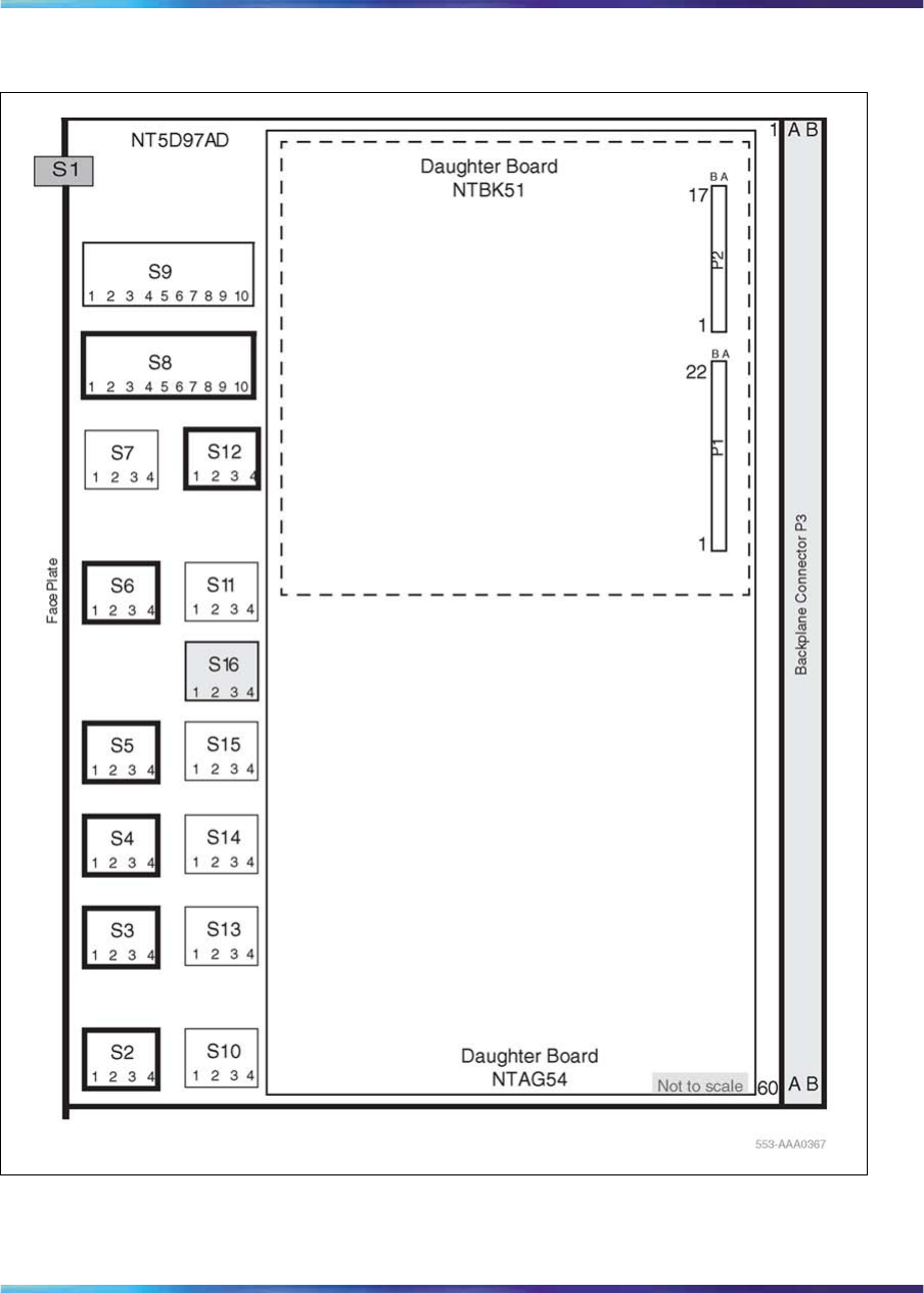
NT5D97AD DIP switch settings 135
Figure 56
Dip switches locations for NT5D97AD
The following parameters are set by DIP switches. The boldface font shows
the factory setup.
Nortel Communication Server 1000
ISDN Primary Rate Interface Installation and Commissioning
NN43001-301 02.03 Standard
Release 5.5 7 December 2007
Copyright © 2003-2007, Nortel Networks
.
136 NT5D97 Dual-port DTI2/PRI2 installation and removal
Trunk interface switches for NT5D97AD
Trunk 0 switches
Switch S12 gives the MPU information about its environment as shown in
Table 46 "General purpose switches for NT5D97AD" (page 136).
Table 46
General purpose switches for NT5D97AD
Switch Description S9/S15 Switch Setting
S12_1 Impedance level OFF - 120 ohm
ON - 75 ohm
S12_2 Spare For future use
S12_3 Spare For future use
S12_4 Unit mode OFF - Unit operates in the DTI2 mode
ON - Unit operates in the PRI2 mode
Switch S2 selects the Transmission mode as shown in Table 47 "TX mode
switches for NT5D97AD" (page 136).
Table 47
TX mode switches for NT5D97AD
TX mode S2
E1 OFF
Not used ON
Switch S3,S4, and S5 select LBO function as is Table 48 "LBO switches
for NT5D97AD" (page 136).
Table 48
LBO switches for NT5D97AD
LBO setting S3 S4 S5
0dB OFF OFF OFF
7.5dB ON ON OFF
15dB ON OFF ON
Switch S6 selects the Receiver interface as in Table 49 "Receiver interface
switches for NT5D97AD" (page 137).
Nortel Communication Server 1000
ISDN Primary Rate Interface Installation and Commissioning
NN43001-301 02.03 Standard
Release 5.5 7 December 2007
Copyright © 2003-2007, Nortel Networks
.
NT5D97AD DIP switch settings 137
Table 49
Receiver interface switches for NT5D97AD
Impedance S6-1 S6-2 S6-3 S6-4
75 ohm OFF OFF ON OFF
120 ohm OFF OFF OFF ON
Trunk 1 switches for NT5D97AD
Table 50
Trunk 1 switches
Switch Function
S7 General Purpose...See Table 46 "General purpose
switches for NT5D97AD" (page 136)
S10 TX Mode...See Table 47 "TX mode switches for NT5D97AD"
(page 136)
S13, S14 & S15 LBO...See Table 48 "LBO switches for NT5D97AD" (page
136)
S11 RX Impedance...See Table 49 "Receiver interface switches
for NT5D97AD" (page 137)
Ring ground switches for NT5D97AD
Switch S16 selects which ring lines connect to ground. When set to ON,
the ring line is grounded as shown in Table 51 "Ring ground switch for
NT5D97AD" (page 137).
Table 51
Ring ground switch for NT5D97AD
Switch Line
S16_1 Trunk 0 Transmit
S16_2 Trunk 0 Receive
S16_3 Trunk 1 Transmit
S16_4 Trunk 1 Receive
DCH Address select switch for NTBK51AA daughter board for
NT5D97AD
Switch S9 selects the NTBK51AA DCH daughterboard address.
Switch S8 is not used when the NTBK51AA daughterboard is used.
S8_1-10 can be set to OFF position as in Table 52 "NTBK51AA DCH
switches for NT5D97AD" (page 138).
Nortel Communication Server 1000
ISDN Primary Rate Interface Installation and Commissioning
NN43001-301 02.03 Standard
Release 5.5 7 December 2007
Copyright © 2003-2007, Nortel Networks
.
138 NT5D97 Dual-port DTI2/PRI2 installation and removal
Table 52
NTBK51AA DCH switches for NT5D97AD
Switch number Function
S9_1-4 DCH daughter card address
S9_5-8 Set to OFF
S9_9 Set to ON (NTBK51AA Mode)
S9_10 Set to ON (NTBK51AA Mode)
MSDL external card
Table 53 "Switch settings for MSDL external card" (page 138) lists the switch
numbers assigned for future use on the MSDL external card.
Table 53
Switch settings for MSDL external card
Switch number Function
S9_1-10 For future use
S8_1-10 For future use
Use Table 54 "Switch setting for MSDL external card" (page 138) to set
the card address.
Table 54
Switch setting for MSDL external card
Switch Setting
DNUM (LD 17) 1234
0OFF OFF OFF OFF
1ON OFF OFF OFF
2OFF ON OFF OFF
3ON ON OFF OFF
4OFF OFF ON OFF
5ON OFF ON OFF
6OFF ON ON OFF
7ON ON ON OFF
8OFF OFF OFF ON
9ON OFF OFF ON
10 OFF ON OFF ON
11 ON ON OFF ON
12 OFF OFF ON ON
Nortel Communication Server 1000
ISDN Primary Rate Interface Installation and Commissioning
NN43001-301 02.03 Standard
Release 5.5 7 December 2007
Copyright © 2003-2007, Nortel Networks
.
Install the NT5D97 DDP2 139
Switch Setting
DNUM (LD 17) 1234
13 ON OFF ON ON
14 OFF ON ON ON
15 ON ON ON ON
Install the NT5D97 DDP2
Use Procedure 14 "Install the NT5D97 on Large Systems" (page 139) to
install the NT5D97 on Large Systems.
CAUTION
The static discharge bracelet located inside the cabinet must be
worn before handling circuit cards. Failure to wear the bracelet
can result in damage to the circuit cards.
Procedure 14
Install the NT5D97 on Large Systems
Step Action
1Determine the cabinet and shelf location where the NT5D97 is to
be installed. The NT5D97 can be installed in any card slot in the
Network bus.
2Unpack and inspect the NT5D97and cables.
3If a DDCH is installed, refer to the section "NTBK51 DDCH
installation and removal" (page 91).
4Set the option switches on the NT5D97 card before installation.
Refer to "NT5D97AA/AB DIP switch settings" (page 129).
The ENB/DIS (enable/disable faceplate switch) must be OFF (DIS)
when installing the NT5D97, otherwise a system initialize can occur.
The ENB/DIS on the NT5D97 corresponds to the faceplate switch
on the QPC414 Network card.
5Install NT5D97 card in the assigned shelf and slot.
6Set the ENB/DIS faceplate switch to ON.
If the DDCH is installed, the DDCH LED should flash three times.
7If required, install the I/O adapters in the I/O panel.
8Run and connect the NT5D97 cables
Nortel Communication Server 1000
ISDN Primary Rate Interface Installation and Commissioning
NN43001-301 02.03 Standard
Release 5.5 7 December 2007
Copyright © 2003-2007, Nortel Networks
.
140 NT5D97 Dual-port DTI2/PRI2 installation and removal
CAUTION
Clock Controller cables connecting the Clock Controller
and NT5D97 card must NOT be routed through the center
of the cabinet past the power harness. Instead they should
be routed around the outside of the equipment shelves.
9If required, install connecting blocks at the MDF or wall mounted
crossconnect terminal.
10 If required, designate connecting blocks at the MDF or wall mounted
crossconnect terminal.
11 If required, install a Network Channel Terminating Equipment
(NCTE). or Line Terminating Unit (LTU).
12 Add related office data into switch memory.
13 Enable faceplate switch S1. This is the "Loop Enable" switch.
The faceplate LEDs should go on for 4 seconds then go off and
the OOS, DIS and ACT LEDs should go on again and stay on.
IF DDCH is installed, the DCH LED should flash 3 times.
14 Run the PRI/DTI Verification Test.
15 Run the PRI status check.
—End—
Remove the NT5D97 DDP2
Use Procedure 15 "Remove the NT5D97 from Large Systems" (page
141) to remove the NT5D97 from Large Systems
CAUTION
The static discharge bracelet located inside the cabinet must be
worn before handling circuit cards. Failure to wear the bracelet
can result in damage to the circuit cards.
Nortel Communication Server 1000
ISDN Primary Rate Interface Installation and Commissioning
NN43001-301 02.03 Standard
Release 5.5 7 December 2007
Copyright © 2003-2007, Nortel Networks
.
Configure the NT5D97 DDP2 141
Procedure 15
Remove the NT5D97 from Large Systems
Step Action
1Determine the cabinet and shelf location of the NT5D97 card to
be removed.
2Disable the Network Loop using LD 60. The command is DISL
"loop number."
The associated DCHI might have to be disabled first. The faceplate
switch ENB/DIS should not be disabled until both PRI2/DTI2 loops
are disabled first.
3Remove data from memory, if the NT5D97 card is being completely
removed, not replaced.
4Remove cross connections at the MDF to wall-mounted crossconnect
terminal.
5Tag and disconnect cables from the card.
6Rearrange Clock Controller cables if required.
CAUTION
Clock Controller cables connecting the Clock Controller
and DDP2 card must NOT be routed through the center of
the cabinet past the power harness. Instead, they should
be routed around the outside of the equipment shelves.
7Remove the DDP2 card only if both loops are disabled. If the other
circuit of a DDP2 card is in use, DO NOT remove the card. The
Faceplate switch ENB/DIS must be in the OFF (DIS) position before
the card is removed, otherwise the system will initialize.
8Pack and store the NT5D97 card and circuit card.
—End—
Configure the NT5D97 DDP2
After the NT5D97 DDP2 is installed, configure the system using the same
procedures as the standard NT8D72BA PRI2.
Nortel Communication Server 1000
ISDN Primary Rate Interface Installation and Commissioning
NN43001-301 02.03 Standard
Release 5.5 7 December 2007
Copyright © 2003-2007, Nortel Networks
.

142 NT5D97 Dual-port DTI2/PRI2 installation and removal
Consider the following when configuring the NT5D97 DDP2 card:
•The system software allows four ports to be defined for the NT6D80
MSDL. The DDCH (NTBK51AA) card has only two ports, 0 and 1;
therefore, ports 2 and 3 must not be defined when using the NTBK51AA.
•Port 0 of the NTBK51AA can only be defined to work with Loop 0 of the
NT5D97 DDP2 card, and Port 1 of the NTBK51AA can only be defined
to work with Loop 1 of the NT5D97. This relationship must be reflected
when configuring a new DCH in LD 17 (in response to the DCHL prompt,
enter either 0 or 1 when specifying the loop number used by the DCH).
•You cannot define one of the DDP2 loops for the NTBK51AA DDCH,
and the other loop for the NT6D11AF, NT5K75AA, and NT5K35AA DCH
card or the NT6D80 MSDL.
•When configuring the NT5D97 DDP2 in DTI2 outgoing dial pulse mode,
a Digit Outpulsing patch is required.
Nortel Communication Server 1000
ISDN Primary Rate Interface Installation and Commissioning
NN43001-301 02.03 Standard
Release 5.5 7 December 2007
Copyright © 2003-2007, Nortel Networks
.

143
NT5D12 Dual-port DTI/PRI card
installation
Contents The section contains information on the following topics:
"Introduction" (page 143)
"NT5D12 circuit card locations" (page 143)
"Port definitions" (page 144)
"Scenarios for replacement of a digital trunk card (QPC720/QPC472) by a DDP
card" (page 144)
"NT5D12 switch settings" (page 145)
"General Purpose Switches" (page 145)
"Trunk interface switches" (page 145)
"Ring ground switches" (page 146)
"DCH mode and address select switches" (page 147)
"Install the NT5D12 DDP" (page 150)
"Remove the NT5D12 DDP" (page 152)
"Configure the NT5D12 DDP" (page 153)
Introduction This section contains information required to install the NT5D12 1.5 Mb
DTI/PRI Dual-port (DDP) card on Large Systems.
For installation and removal procedures for the NTBK51AA Downloadable
D-channel daughterboard, refer to the section "NTBK51 DDCH installation
and removal" (page 91).
NT5D12 circuit card locations
Each NT5D12 circuit card requires one slot on a shelf. NT5D12 cards can
be placed in any card slot in the network bus, subject to the cautionary
note below.
Nortel Communication Server 1000
ISDN Primary Rate Interface Installation and Commissioning
NN43001-301 02.03 Standard
Release 5.5 7 December 2007
Copyright © 2003-2007, Nortel Networks
.

144 NT5D12 Dual-port DTI/PRI card installation
Port definitions
Since the NT5D12 card is dual-card, it equips two ports. These ports are
defined in the following combinations:
Port 0 Port 1
DTI DTI
DTI PRI
PRI DTI
PRI PRI
DTI Not configured
PRI Not configured
Not configured PRI
Not configured DTI
Scenarios for replacement of a digital trunk card (QPC720/QPC472)
by a DDP card
The following discussion describes possible scenarios when replacing a
digital trunk QPC720 PRI card or QPC472 DTI card configuration with a
NT5D12 DDP card configuration.
Case 1 - The two ports of a QPC414 network card are connected to two
digital trunks.
In this case, the QPC414 and the two digital trunks are replaced by a single
DDP card, which is plugged into the CE shelf in the QPC414 slot.
Case 2 - One port of the QPC414 card is connected to a digital trunk,
and the second is connected to a peripheral buffer. Both cards are in the
network loop location.
In this case, the QPC414 should not be removed. The digital trunk is
removed and the DDP card is plugged into one of the two empty slots.
Case 3 - The CE shelf is full, one port of a QPC414 network card is
connected to a digital trunk, and the second is connected to a peripheral
buffer. This arrangement is repeated for another QPC414. The digital trunks
are located in a shelf that provides only power.
In this case, the peripheral buffers will have to be reassigned, so that each
pair of buffers will use both ports of the same QPC414 card. The other
QPC414 card can then be replaced by the NT5D12 DDP.
Nortel Communication Server 1000
ISDN Primary Rate Interface Installation and Commissioning
NN43001-301 02.03 Standard
Release 5.5 7 December 2007
Copyright © 2003-2007, Nortel Networks
.

NT5D12 switch settings 145
Note in all cases - If a QPC720 card is being replaced by a DDP card, the
D-channel Handler or MSDL can be either reconnected to the DDP card, or
removed if an onboard NTBK51AA DDCH card is used.
NT5D12 switch settings
The NT5D12 card is equipped with 6x2 sets of DIP switches for trunk
parameters settings for port0 and port1 respectively. Additionally, the
NT5D12 card is equipped with one set of four DIP switches for the Ring
Ground setting and one set of eight DIP switches for the D-channel Handler
parameters setting.
The DIP switches are used for setting of default values of certain
parameters. The general purpose switches are read by the firmware which
sets the default values accordingly.
The following parameters are being set by the DIP switches. Factory setups
are shown in bold.
General Purpose Switches
A per-trunk set of four DIP switches provides the default setting for
operational modes. Switch set S9 is used for Trunk 0. Switch set S15 is used
for Trunk 1. Refer to Table 55 "General purpose switch settings" (page 145)’.
Table 55
General purpose switch settings
Switch Description S9/S15 Switch Setting
1Framing Mode OFF - ESF
ON - SF
2Yellow Alarm Method OFF - FDL
ON - Digit2
3Zero Code Suppression
Mode OFF - B8ZS
ON - AMI
4Unused OFF
Trunk interface switches
Transmission Mode
A per-trunk switch provides selection for T1 transmission. See Table 56
"Trunk interface transmission mode switch settings" (page 146).
Nortel Communication Server 1000
ISDN Primary Rate Interface Installation and Commissioning
NN43001-301 02.03 Standard
Release 5.5 7 December 2007
Copyright © 2003-2007, Nortel Networks
.
146 NT5D12 Dual-port DTI/PRI card installation
Table 56
Trunk interface transmission mode switch settings
Description S4/S10 Switch Setting
For future use. OFF
T1 ON
Line Build Out
A per-trunk set of three switches provides a selection between 0, 7.5 or 15
dB values. See Table 57 "Trunk interface line build out switch settings"
(page 146).
Table 57
Trunk interface line build out switch settings
Description Switch Setting
S5/S11 S6/S12 S7/S13
0dB OFF OFF OFF
7.5 dB ON ON OFF
15 dB ON OFF ON
Receiver Impedance
A per trunk set of four DIP switches provides a selection between 75, 100
or 120 values. See Table 58 "Trunk interface receiver impedance switch
settings" (page 146).
Table 58
Trunk interface receiver impedance switch settings
Description S8/S14 Switch Setting
75 OFF OFF ON OFF
100 ON OFF OFF ON
120 OFF OFF OFF ON
Ring ground switches
A set of four DIP switches selects which Ring lines are connected to the
ground. See Table 59 "Ring ground switch settings" (page 147).
Nortel Communication Server 1000
ISDN Primary Rate Interface Installation and Commissioning
NN43001-301 02.03 Standard
Release 5.5 7 December 2007
Copyright © 2003-2007, Nortel Networks
.

NT5D12 switch settings 147
Table 59
Ring ground switch settings
Switch Description S2 Switch Setting
1Trunk 0 Transmit OFF - Ring line is not grounded
ON - Ring line is grounded
2Trunk 0 Receive OFF - Ring line is not grounded
ON - Ring line is grounded
3Trunk 1 Transmit OFF - Ring line is not grounded
ON - Ring line is grounded
4Trunk 1 Receive OFF - Ring line is not grounded
ON - Ring line is grounded
DCH mode and address select switches
A set of eight DIP switches selects between an onboard NTBK51AA
D-channel daughterboard and an external MSDL/DCHI card. In the case
of an onboard NTBK51AA D-channel daughterboard, four of the switches
provide the daughterboard address. See Table 60 "DCH mode and address
select switch settings" (page 147).
Table 60
DCH mode and address select switch settings
Switch Description S3 Switch Setting
1-4 D-channel daughterb
oard
Address
See Table 61 "NTBK51AA daughterboard
address select switch settings" (page 148)
5-7 For future use. OFF
8External DCH or
Onboard DDCH OFF - MSDL or DCHI card
ON - Onboard DDCH daughterboard
Nortel Communication Server 1000
ISDN Primary Rate Interface Installation and Commissioning
NN43001-301 02.03 Standard
Release 5.5 7 December 2007
Copyright © 2003-2007, Nortel Networks
.
148 NT5D12 Dual-port DTI/PRI card installation
Table 61
NTBK51AA daughterboard address select switch settings
Device
Address1Switch Setting
02OFF OFF OFF OFF
1ON OFF OFF OFF
2OFF ON OFF OFF
3ON ON OFF OFF
4OFF OFF ON OFF
5ON OFF ON OFF
6OFF ON ON OFF
7ON ON ON OFF
8OFF OFF OFF ON
9ON OFF OFF ON
10 OFF ON OFF ON
11 ON ON OFF ON
12 OFF OFF ON ON
13 ON OFF ON ON
14 OFF ON ON ON
15 ON ON ON ON
Note 1: The maximum number of DCHI, MSDL, and DDCH devices in the system is 16.
Note 1: The Device Addresses are equivalent to the MSDL DNUM designations.
Note 2: Device address 0 is commonly assigned to the System Monitor.
Nortel Communication Server 1000
ISDN Primary Rate Interface Installation and Commissioning
NN43001-301 02.03 Standard
Release 5.5 7 December 2007
Copyright © 2003-2007, Nortel Networks
.
NT5D12 switch settings 149
Figure 57
Switch functional areas on the NT5D12
Nortel Communication Server 1000
ISDN Primary Rate Interface Installation and Commissioning
NN43001-301 02.03 Standard
Release 5.5 7 December 2007
Copyright © 2003-2007, Nortel Networks
.
150 NT5D12 Dual-port DTI/PRI card installation
Figure 58
NT5D12 switch default settings
Install the NT5D12 DDP
Use Procedure 16 "Install the NT5D12 on Large Systems" (page 151) to
install the NT5D12 on Large Systems.
CAUTION
The static discharge bracelet located inside the cabinet must be
worn before handling circuit cards. Failure to wear the bracelet
can result in damage to the circuit cards.
Nortel Communication Server 1000
ISDN Primary Rate Interface Installation and Commissioning
NN43001-301 02.03 Standard
Release 5.5 7 December 2007
Copyright © 2003-2007, Nortel Networks
.
Install the NT5D12 DDP 151
Procedure 16
Install the NT5D12 on Large Systems
Step Action
1Determine the cabinet and shelf location where the NT5D12 card is
to be installed. The NT5D12 can be installed in any card slot in the
Network bus, subject to the cautionary note below.
CAUTION
Some installed-based systems can have a Bus
Terminating Unit (BTU) already installed. This can
interfere with a selected NT5D12 card location. In such
cases, the NT5D12 should be installed in an alternate
network bus card slot location.
2Unpack and inspect circuit cards and cables.
3If a DDCH is to be installed, refer to "NTBK51 DDCH installation
and removal" (page 91).
4Set the option switches on the NT5D12 circuit card before
installation. Refer to "NTBK51 DDCH installation and removal"
(page 91).
S1 (faceplate switch) must be OFF (DIS) when installing the
NT5D12. S1 on the NT5D12 corresponds to the faceplate switch
on the QPC414 Network card.
5Install the NT5D12 circuit card in the assigned shelf and slot.
6Add related office administration data into the system memory.
7If required, install the I/O adapters in the I/O panel.
8Run and connect the NT5D12 cables.
CAUTION
Clock Controller cables connecting the Clock Controller
and NT5D12 card must NOT be routed through the center
of the cabinet past the power harness. Instead, route
them around the outside of the equipment shelves.
9If required, install connecting blocks at the MDF or wall mounted
crossconnect terminal.
10 If required, designate connecting blocks at the MDF or wall mounted
crossconnect terminal.
Nortel Communication Server 1000
ISDN Primary Rate Interface Installation and Commissioning
NN43001-301 02.03 Standard
Release 5.5 7 December 2007
Copyright © 2003-2007, Nortel Networks
.
152 NT5D12 Dual-port DTI/PRI card installation
11 If required, install Network Channel Terminating Equipment (NCTE).
12 Enable faceplate switch S1. This is the "Loop Enable" switch.
The faceplate LEDs should go on for 4 seconds then go off and the
OOS, DIS and ACT LEDs should go on again and stay on.
IF DDCH is installed, the DCH LED should flash 3 times.
13 Run PRI/DTI Verification Test.
14 Run PRI status check.
—End—
Remove the NT5D12 DDP
Use Procedure 17 "Remove the NT5D12 DDP" (page 152) to remove the
NT5D12 from Large Systems.
CAUTION
A static discharge bracelet must be worn before handling circuit
cards. Failure to wear the bracelet can result in damage to the
circuit cards.
Procedure 17
Remove the NT5D12 DDP
Step Action
1Determine the cabinet and shelf location of the NT5D12 card to
be removed.
2Disable Network Loop using LD 60. The command is DISL "loop
number."
The associated DCHI might have to be disabled first. The faceplate
switch S1 should not be disabled until both PRI loops are disabled
first.
3Remove data from memory, if the NT5D12 card is being completely
removed, not replaced.
4Remove cross connections at the MDF to wall-mounted crossconnect
terminal.
5Tag and disconnect cables from card.
6Rearrange Clock Controller cables if required.
Nortel Communication Server 1000
ISDN Primary Rate Interface Installation and Commissioning
NN43001-301 02.03 Standard
Release 5.5 7 December 2007
Copyright © 2003-2007, Nortel Networks
.

Configure the NT5D12 DDP 153
CAUTION
Clock Controller cables connecting the Clock Controller
and NT5D12 card must NOT be routed through the center
of the cabinet past the power harness. Instead they should
be routed around the outside of the equipment shelves.
7Determine if the other circuit of a NT5D12 card is in use.DO NOT
remove the card if in use.
8Remove the NT5D12 card only if both loops are disabled. Switch
S1 (faceplate switch) must be in the OFF (DIS) position before the
card is removed.
9Pack and store the NT5D12 card and circuit card.
—End—
Configure the NT5D12 DDP
After the NT5D12 DDP has been installed, it can be configured using the
same procedures as for the standard QPC720 PRI card.
Consider the following when configuring the NT5D12 DDP card:
•The system software allows four ports to be defined for the NT6D80
MSDL. The DDCH (NTBK51AA) card has only two ports, 0 and 1;
therefore, ports 2 and 3 must not be defined when using the NTBK51AA.
•Port 0 of the NTBK51AA can only be defined to work with Loop 0 of the
NT5D12 DDP card, and Port 1 of the NTBK51AA can only be defined
to work with Loop 1 of the NT5D12. This relationship must be reflected
when configuring a new DCH in LD 17 (in response to the DCHL prompt,
enter either 0 or 1 when specifying the loop number used by the DCH).
•You cannot define one of the NT5D12 loops for the NTBK51AA DDCH,
and the other loop for the QPC757 DCHI or the NT6D80 MSDL.
Nortel Communication Server 1000
ISDN Primary Rate Interface Installation and Commissioning
NN43001-301 02.03 Standard
Release 5.5 7 December 2007
Copyright © 2003-2007, Nortel Networks
.

154 NT5D12 Dual-port DTI/PRI card installation
Nortel Communication Server 1000
ISDN Primary Rate Interface Installation and Commissioning
NN43001-301 02.03 Standard
Release 5.5 7 December 2007
Copyright © 2003-2007, Nortel Networks
.

155
Clock Controller description and
installation
Contents The section contains information on the following topics:
"Introduction" (page 156)
"Description" (page 156)
"Need for synchronization" (page 156)
"Supported Clock Controllers" (page 157)
"Synchronization methods" (page 158)
"Hierarchical synchronization" (page 159)
"Stratum levels" (page 160)
"Frame slip" (page 160)
"Guidelines" (page 161)
"Modes of operation" (page 167)
"Small System Clock Controller daughterboard" (page 168)
"Installation procedures" (page 168)
"Determine slots and shelves" (page 168)
"Set switches" (page 169)
"Start the Clock Controller" (page 171)
"Clock Controller commands" (page 171)
"Install or replace a Clock Controller on a Half Group and Single Group
system" (page 171)
"Install or replace a Clock Controller on a Single Group and Multi Group
System" (page 173)
"Upgrade to an NTRB53 Clock Controller on a Single Group and Multi Group
System" (page 175)
Nortel Communication Server 1000
ISDN Primary Rate Interface Installation and Commissioning
NN43001-301 02.03 Standard
Release 5.5 7 December 2007
Copyright © 2003-2007, Nortel Networks
.

156 Clock Controller description and installation
Introduction This chapter introduces the NTRB53 Clock Controller, and provides
procedures on how to install this clock controller on Large Systems.
The NTRB53 Clock Controller replaces the QPC471H and QPC775F in
new systems. QPC471H and QPC775F Clock Controllers continue to be
supported.
Note: The NTRB53 Clock Controller cannot be combined with a
QPC775 or a QPC471 card in one system
The illustrations used in the description section depict a Small System.
However, the system can also be representative of a Large System.
Description This section provides an overview on the use of clock controllers. For Large
Systems, the following clock controllers are supported:
•NTRB53
•QPC471
•QPC775
Note: Clock controllers cannot be mixed in one system.
The NTRB53 Clock Controller is available for all markets. The QPC471
Clock Controller is available for U.S. markets. Vintages A through G of the
QPC471 Clock Controller can be used in one system; vintage H of QPC471
Clock Controllers cannot be mixed with clock controllers of other vintages.
The QPC775E Clock Controller card is available for only Canadian and
International markets.
Need for synchronization
Digital trunking requires synchronized clocking so that a shift in one clock
source will result in an equivalent shift of the same size and direction in all
parts of the network.
When digital signals are being transported over a communication link,
the receiving end must operate at the same frequency (data rate) as
the originating end to prevent loss of information. This is referred to
as link synchronization. If both ends of a communication link are not
in synchronization, data bit slips occur and therefore a loss of data
results. In general, accurate timing is very important, but more importantly
synchronized timing is a must for reliable data transfer.
Nortel Communication Server 1000
ISDN Primary Rate Interface Installation and Commissioning
NN43001-301 02.03 Standard
Release 5.5 7 December 2007
Copyright © 2003-2007, Nortel Networks
.

Description 157
When only two switches are interconnected, synchronization can be
achieved by operating the two systems in a master/slave mode whereby one
system derives its timing from the other. However, in a network of digital
systems, slips can be better prevented by forcing all digital systems to use
a common reference clock (see Figure 59 "Hierarchical Synchronization"
(page 159)).
Supported Clock Controllers
For Large Systems, the following clock controllers are supported:
•NTRB53
•QPC471
•QPC775
NTRB53 Clock Controller
The NTRB53 Clock Controller is a replacement for the QPC471 and
QPC775 Clock Controllers. The NTRB53 clock controller retains existing
functionality.
Software configuration of the clock remains unchanged. A PSDL object
allows field upgrades of the clock’s firmware. Overlay changes allow for
force download and status checking. Support for the IDC command and
hardware inventory are also included.
System Initialization During system initialization, the system software will
verify if the clock controllers equipped in the system are the downloadable
clock controllers (NTRB53) or not. If the clock controllers are identified as
the downloadable clock controller cards, then both downloadable clock
controller cards will be checked for the software version number they are
running with. This is compared with the version number of the PSDL file
stored in the system software database.
If there is a mismatch between the two version numbers and the system
database has the higher version number, the card will be put in the PSDL
downloading tree. Once the entry is added in the PSDL tree, the preprocess
step is done. The next step is for the system to initiate the downloading in
the background, using the PSDL tree. As soon as the download complete
message is received from the card, the CPU sends a message to reset the
clock controller card so that it boots with the new software. Once a self-test
is complete the core sends an enable base message to enable the card.
Maintenance Overlays Downloading can be initiated from LD 60 for the
inactive clock controller card as part of the enabling sequence of the card. A
download can be forced by specifying the optional parameter FDL (Force
Download) when enabling the card. At the prompt, enter:
Nortel Communication Server 1000
ISDN Primary Rate Interface Installation and Commissioning
NN43001-301 02.03 Standard
Release 5.5 7 December 2007
Copyright © 2003-2007, Nortel Networks
.

158 Clock Controller description and installation
ENL CC x FDL Enable Clock in side x with the force download option
If the optional parameter is not specified, then downloading is conditional.
This means that the version number of the loadware on the clock controller
card will be checked against the version number stored on the system disk.
If a mismatch is found and the version number in the system software
database is higher, then downloading will be initiated for that card. The entry
for the card is not added to the PSDL tree at this time. Instead, downloading
is initiated on a single card and only that card will be allowed to perform
the force download option.
QPC471 and QPC775 Clock Controllers
Clock Controllers QPC471 and QPC775 will continue to function with:
•CS 1000M HG systems
•CS 1000M SG systems
•CS 1000M MG systems
Note: "Description" (page 156) for market and application availability
information.
Synchronization methods
There are two common methods of operation for maintaining timing
coordination between switching systems, Plesiosynchronous and
Mesosynchronous.
Plesiosynchronous operation
In a Plesiosynchronous operation, nodal clocks run independently (free run)
at the same nominal frequency. There are frequency differences between
clocks resulting in frame slips (see "Frame slip" (page 160).) The magnitude
of frame slips are directly proportional to the frequency difference. Slips are
inevitable but can be minimized by using very stable clocks and elastic
stores or buffers. These buffers are capable of absorbing a certain number
of data bits to compensate for slight variances in clock frequencies.
Mesosynchronous operation
In a Mesosynchronous operation, nodal clocks are continuously and
automatically locked to an external reference clock. With this method, frame
slips can be eliminated if elastic stores are large enough to compensate for
transmission variances. Mesosynchronous operation is virtually slip free.
Whenever possible the system uses the Mesosynchronous mode of
operation by using the clock controller circuit cards to lock onto an external
reference source (such as the Central Office, another PBX, and so on).
This statement is true unless the system is used as a Master in an
independent/private network (no digital links to a higher Node Category).
Nortel Communication Server 1000
ISDN Primary Rate Interface Installation and Commissioning
NN43001-301 02.03 Standard
Release 5.5 7 December 2007
Copyright © 2003-2007, Nortel Networks
.

Description 159
In an isolated private network, the clock controller can operate in free run
mode and act as a master clock to be tracked by other PBX systems in
the private network.
Hierarchical synchronization
Figure 59 "Hierarchical Synchronization" (page 159) provides a general
view of the Digital Network Clock Synchronization including the four stratum
level Node Categories. Stratum 1 being the most accurate and Stratum 4
being the least accurate. System clocking meets Node Category E Stratum
4 requirements. Also shown are ways of providing a Secondary Clock
Source while preventing timing loops.
Figure 59
Hierarchical Synchronization
Nortel Communication Server 1000
ISDN Primary Rate Interface Installation and Commissioning
NN43001-301 02.03 Standard
Release 5.5 7 December 2007
Copyright © 2003-2007, Nortel Networks
.
160 Clock Controller description and installation
Stratum levels
In a digital network, nodes are synchronized using a priority master/slave
method. Digital nodes are ranked in Stratum levels 1 to 5. Each node is
synchronized to the highest ranking node in its neighborhood with which it
has a direct link. Refer to Table 62 "Node categories and stratum levels"
(page 160).
Table 62
Node categories and stratum levels
Stratum 2 Stratum 3 Stratum 4
Accuracy +/- 1.6 * 10-8 Hz +/- 4.6 * 10-6 Hz +/- 3.2 * 10-5 Hz
Holdover 1*10
-10 per day <= 255 frame slips in
1st 24 hours Not Required
Hardware Duplication Required Required (Note 1) Not Required
MTIE During
Rearrangement MTIE <= 1 usec Phase
Change Slope: <= 81
ns in any 1.326 msec
MTIE <= 1 usec Phase
Change Slope: <= 81
ns in any 1.326 msec
No Requirement (Note
2)
Pull-in Range +/- 1.6 * 10-8 Hz +/- 4.6 * 10-6 Hz +/- 3.2 * 10-5 Hz
Dedicated Timing
Required Required Required Not required
Note 1: Non-duplicated clock hardware that meets all other stratum 3
requirements is referred to as stratum 3ND.
Note 2: Stratum 4 clock hardware that meets MTIE requirements during
rearrangements is referred to as 4E.
Frame slip
Digital signals must have accurate clock synchronization for data to
be interleaved into or extracted from the appropriate timeslot during
multiplexing and demultiplexing operations. A Frame Slip is defined (for 2
Mbyte links) as the repetition of, or deletion of the 256 data bits of a CEPT
frame due to a sufficiently large discrepancy in the read and write rates at
the buffer (clocks are not operating at exactly the same speed).
When data bits are written into (added to) a buffer at a slightly higher rate
than that at which they are being read (emptied), sooner or later the buffer
overflows This is a slip-frame deletion.
In the opposite situation, when data bits are written (added) into a buffer
at slightly lower rate than that at which they are being read (emptied),
eventually the buffer runs dry or underflows. This is also a slip-frame
repetition.
Nortel Communication Server 1000
ISDN Primary Rate Interface Installation and Commissioning
NN43001-301 02.03 Standard
Release 5.5 7 December 2007
Copyright © 2003-2007, Nortel Networks
.
Description 161
A 1.5 Mbyte PRI contains a buffer large enough to hold about 2 full DS-1
frames (193 x 2 = 386). A 2 Mbyte PRI contains a buffer large enough to
contain 2 full frames (256 x 2 = 512 bits). The buffer is normally kept half
full (1 frame).
Slippage has impact on the data being transferred, as is shown in Table 63
"Performance impact of one slip on service type" (page 161). All of the
degradations shown in the table can be controlled or avoided with proper
clock synchronization.
Table 63
Performance impact of one slip on service type
Service Potential Impact
Encrypted Text Encryption key must be resent.
Video Freeze frame for several seconds. Loud pop
on audio.
Digital Data Deletion or repetition of data. Possible
misframe.
Facsimile Deletion of 4 to 8 scan lines. Dropped call.
Voice Band Data Transmission Errors for 0.01 to 2 s. Dropped
call.
Voice Possible click.
Guidelines
Some key points to keep in mind when designing Network Synchronization:
•Where possible, the Master Clock Source should always be from a Node
Category/Stratum with higher clock accuracy, that is, a PBX connected to
the Central Office (CO.) The CO is the Master and the PBX is the Slave.
•The source should not be in free-run itself (providing its own clock)
unless it is operating in a fully independent network where the source
acts as a Master (see "Plesiosynchronous operation" (page 158).)
•When connecting two PBXs together (no CO connections), the most
reliable PBX should be the Master. Reliability here refers to Dual
CPU/Dual Clock, battery back-up or stratum level of the clock controller.
•Avoid timing loops. A timing loop occurs when a clock using as its
reference frequency a signal that it itself traceable to the output of that
clock. The formation of such a closed timing loop leads to frequency
instability and is not permitted. Timing loops are sometimes unavoidable
on the secondary clock reference source.
•Ensure all CO/PBX links used as clock references have a traceable path
back to the same stratum 1 clock source.
Nortel Communication Server 1000
ISDN Primary Rate Interface Installation and Commissioning
NN43001-301 02.03 Standard
Release 5.5 7 December 2007
Copyright © 2003-2007, Nortel Networks
.
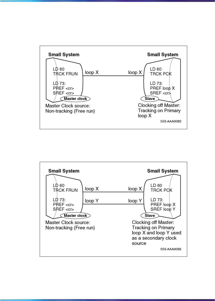
162 Clock Controller description and installation
While it is beyond the scope of this discussion to provide detailed Network
Synchronization, the following examples illustrate some of the basic
concepts to achieve stable clocking.
Figure 60
Example 1, Isolated Private Network
In this example, there is no digital connection to the Central Office.
Figure 61
Example 2, Isolated Private Network with Secondary Reference Clock
In this example, there is no digital connection to the Central Office. For tie
lines between PBXs facilitated by a central office, clocking is derived from
the PBX, not the CO. When a second Digital loop is available, it can be used
as a Secondary Clock source in case the Primary Source fails.
Nortel Communication Server 1000
ISDN Primary Rate Interface Installation and Commissioning
NN43001-301 02.03 Standard
Release 5.5 7 December 2007
Copyright © 2003-2007, Nortel Networks
.
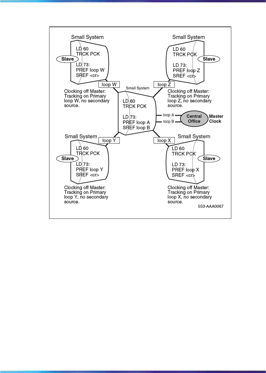
Description 163
Figure 62
Example 3, Clocking Hierarchy referenced to a Public Network Master Clock
This is an example of a "STAR" arrangement— one Hub PBX is linked to
the Central Office and all other PBXs are connected as slaves. When a
second Digital loop from the system which forms the hub of this network
becomes available, it can be used as a Secondary Clock Source in case the
Primary Source fails.
Nortel Communication Server 1000
ISDN Primary Rate Interface Installation and Commissioning
NN43001-301 02.03 Standard
Release 5.5 7 December 2007
Copyright © 2003-2007, Nortel Networks
.

164 Clock Controller description and installation
Figure 63
Example 4, Alternate Clocking from the same CO
In this case, a digital connection to the Central Office can exist (i.e. Loops X
and Y). When a second Digital loop from the CO or Master M-1 becomes
available, it can be used as a Secondary Clock Source in case the Primary
Source fails.
To avoid timing loops, in example 4-4 the most reliable slave system should
not have a Secondary Clock Source (SREF= <cr>). In this example, this is
illustrated by the node which supports loops X and Z.
Nortel Communication Server 1000
ISDN Primary Rate Interface Installation and Commissioning
NN43001-301 02.03 Standard
Release 5.5 7 December 2007
Copyright © 2003-2007, Nortel Networks
.
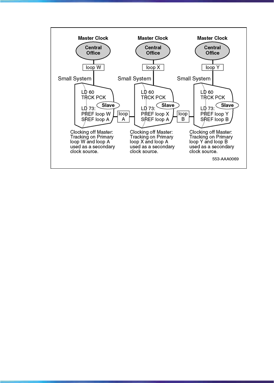
Description 165
Figure 64
Example 5, digital connection to the CO
In this example, digital connections to the Central Office do exist. When a
second Digital loop from the CO becomes available, it can be used as a
Secondary Clock Source in case the Primary Source fails.
Slaves can track on each other as a secondary source since the chances of
both links to the Central Offices going down at the same time are minimal.
All Central Offices must have a path back to the same stratum 1 source.
Nortel Communication Server 1000
ISDN Primary Rate Interface Installation and Commissioning
NN43001-301 02.03 Standard
Release 5.5 7 December 2007
Copyright © 2003-2007, Nortel Networks
.

166 Clock Controller description and installation
Figure 65
Example 6, Complex Isolated Private Network
Digital connections to the Central Office do not exist in this example. If it
does, the PBX connected to it will track off the CO and will in turn be used
as a clock source to other nodes.
When a second Digital loop from the Master system becomes available, it
can be used as a Secondary Clock Source in case the Primary Source fails.
Nortel Communication Server 1000
ISDN Primary Rate Interface Installation and Commissioning
NN43001-301 02.03 Standard
Release 5.5 7 December 2007
Copyright © 2003-2007, Nortel Networks
.
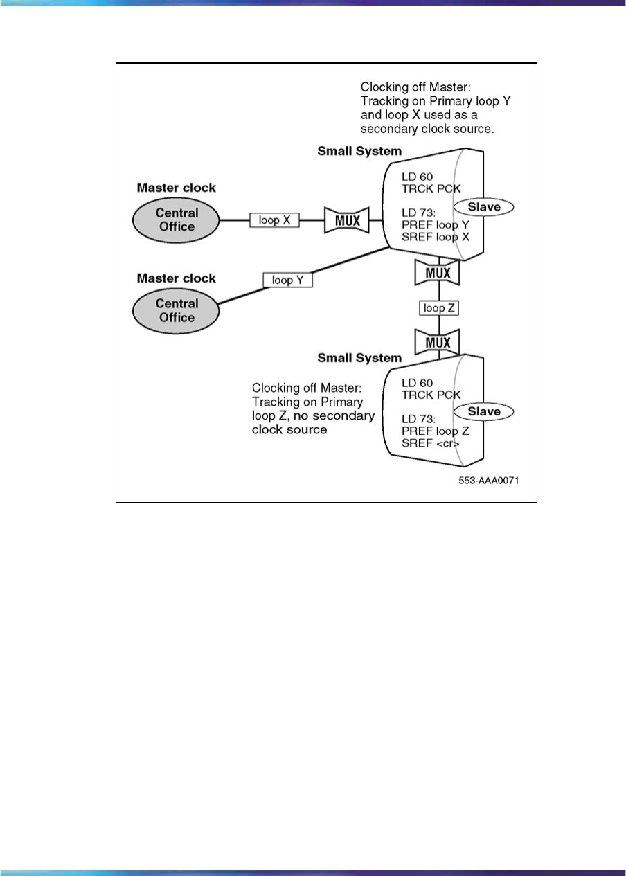
Description 167
Figure 66
Example 7, Network Clocking with MUX
In this example, the direct connection to the CO (without a MUX) should be
used as a primary clock reference because this is where the least amount of
hardware is involved. The MUX must pass the clock and not generate its
own clock; in other words, it must be a slave (not Free Run). Synchronized
clocking is required.
Modes of operation
There are two modes of operation, tracking mode and free run (non-tracking)
mode.
Tracking mode
In tracking mode, the Primary Rate Interface (PRI) or Digital Trunk Interface
(DTI) loop supplies an external clock reference to the onboard clock
controller. Two PRI or DTI packs can operate in tracking mode, with one
defined as the primary reference source for clock synchronization, the other
defined as a secondary reference source. The secondary reference acts as
a back-up to the primary reference.
Nortel Communication Server 1000
ISDN Primary Rate Interface Installation and Commissioning
NN43001-301 02.03 Standard
Release 5.5 7 December 2007
Copyright © 2003-2007, Nortel Networks
.

168 Clock Controller description and installation
Free run (non-tracking) mode
The clock synchronization for a PRI loop can operate in free-run mode if:
•the loop is not defined as the primary or secondary clock reference
•the primary and secondary references are disabled
•the primary and secondary references are in a local alarm state
Small System Clock Controller daughterboard
The Small System supports a single onboard clock controller daughterboard,
the NTAK20, located on either:
•the NTRB21 1.5 Mbyte DTI/PRI card
•the NTAK09 1.5 DTI/PRI card
•the NTAK10 2 Mbyte DTI card
•the NTAK79 2 Mbyte PRI card
•the NTBK50 2 Mbyte PRI card
The clock controller circuitry synchronizes to an external reference clock and
generates and distributes the clock to the system. This enables the system
to function either as a slave to an external clock or as a clocking master.
Note: When configuring ISL over analog trunks, clock controllers are
not required.
Installation procedures
This section provides procedures on how to install a clock controller on
Large Systems.
CAUTION
Do not deviate from the procedures described in this section. Call
processing can stop if procedural steps are not followed properly.
Determine slots and shelves
Table 64 "Clock Controller shelves and slots" (page 169) shows the systems,
the shelves and available slots.
Nortel Communication Server 1000
ISDN Primary Rate Interface Installation and Commissioning
NN43001-301 02.03 Standard
Release 5.5 7 December 2007
Copyright © 2003-2007, Nortel Networks
.

Installation procedures 169
Table 64
Clock Controller shelves and slots
System Shelf Slot(s)
Half Group,
Single Group NT6D39 CPU/NET 9
Multi Group NTDA35 Network Module 13
Set switches
Before installing a clock controller, set the switches as shown in Table 65
"Clock Controller switch settings for QPC471 vintage H" (page 169),Table
66 "Clock Controller switch settings for QPC775" (page 170), and Table 67
"Clock Controller switch settings for NTRB53" (page 170).Table 65 "Clock
Controller switch settings for QPC471 vintage H" (page 169) displays the
settings for different vintages of the QPC471. Table 66 "Clock Controller
switch settings for QPC775" (page 170) shows the settings for the QPC775.
Table 67 "Clock Controller switch settings for NTRB53" (page 170) shows
settings for the NTRB53.
Table 65
Clock Controller switch settings for QPC471 vintage H
SW1 SW2 SW4
System 1 2 3 4 1 2 3 4 1 2 3 4
Half Group, Single Group on on on on off off off off off on **
Option 81 off off off off off off off off off on **
Multi Group (with the exception of
Option 81)
on off off off off off off off ** on **
Multi Group with Fiber Network on off off off off off off off ** on **
* If there is only one clock controller card in the system, set to OFF. If there are two clock
controller cards, determine the total cable length between the J3 connectors (no single cable
can exceed 25 ft.) and set these two switch positions for this cable length, as shown above. The
maximum total (combined) length is 50 ft. Set the switches on both cards to the same settings.
** Set to ON for clock controller 0. Set to OFF for clock controller 1.
Note: FNF based-systems the total clock path length is equal to the length of the NTRC49 cable
used to connect between the two clock controller cards.
Nortel Communication Server 1000
ISDN Primary Rate Interface Installation and Commissioning
NN43001-301 02.03 Standard
Release 5.5 7 December 2007
Copyright © 2003-2007, Nortel Networks
.
170 Clock Controller description and installation
SW1 SW2 SW4
System 1 2 3 4 1 2 3 4 1 2 3 4
*Cable length between the
J3 faceplate connectors:
0–4.3 m (0–14 ft) off off
4.6–6.1 m (15–20 ft) off on
6.4–10.1 m (21–33 ft) on off
10.4–15.2 m (34–50 ft) on on
* If there is only one clock controller card in the system, set to OFF. If there are two clock
controller cards, determine the total cable length between the J3 connectors (no single cable
can exceed 25 ft.) and set these two switch positions for this cable length, as shown above. The
maximum total (combined) length is 50 ft. Set the switches on both cards to the same settings.
** Set to ON for clock controller 0. Set to OFF for clock controller 1.
Note: FNF based-systems the total clock path length is equal to the length of the NTRC49 cable
used to connect between the two clock controller cards.
Table 66
Clock Controller switch settings for QPC775
System SW2 SW3 SW4
Half Group, Single Group ON OFF ON
Multi Group OFF OFF ON
Table 67
Clock Controller switch settings for NTRB53
Multigroup/
Single group
Machine
Type # 1
Faceplate
Cable Length
(CC to CC)
Side Number Machine
Type #2
1234 56
Multigroup
= Off
Single group =
On
61, 51C, 61C
71, 81, 81C
=On
Off Off 0-14 ft Side 0 = On
Side 1 = Off
81 = Off
51, 51C
61, 61C, 81C =
On
Off On 15-20 ft
On Off 21-33 ft
On On 34-50 ft
Nortel Communication Server 1000
ISDN Primary Rate Interface Installation and Commissioning
NN43001-301 02.03 Standard
Release 5.5 7 December 2007
Copyright © 2003-2007, Nortel Networks
.

Installation procedures 171
Note: Switches 7 and 8 are not used.
Start the Clock Controller
The clock controller, when first enabled, is in free run mode. It stays in this
mode for several minutes before being switched to tracking mode. Manual
mode setting is possible using LD 60.
All clock controllers begin tracking within approximately 15 minutes.
Clock Controller commands
During the installation procedure you will use some of the clock controller
commands available in LD 39 and LD 60. Refer to Software Input Output
Reference — Maintenance (NN43001-711).
LD 39 commands with the NTRB53 Clock Controller
Command Description
DIS SCG x Disable SCG card x (0 or 1).
Not applicable for NTRB53 Clock Controller. Use LD 60 instead.
ENL SCG x Enable SCG x (0 or 1).
Not applicable for NTRB53 Clock Controller. Use LD 60 instead.
SCLK Switch clock to other SCG.
Functions with NTRB53 Clock Controller
STAT SCG x Print status of SCG x (0 or 1).
Prints normal status of NTRB53 (not full status)
Install or replace a Clock Controller on a Half Group and Single Group
systemProcedure 18 "Install a clock controller for Half Group and Single Group
Systems." (page 171) outlines the steps to install a clock controller on Half
Group and Single Group systems.
Procedure 18
Install a clock controller for Half Group and Single Group Systems.
Step Action
1Unpack and inspect the circuit card.
2Determine the cabinet and shelf location. Refer to Table 64 "Clock
Controller shelves and slots" (page 169).
3Set the clock controller switch. Refer to Table 65 "Clock Controller
switch settings for QPC471 vintage H" (page 169),Table 66 "Clock
Controller switch settings for QPC775" (page 170),orTable 67
"Clock Controller switch settings for NTRB53" (page 170).
Nortel Communication Server 1000
ISDN Primary Rate Interface Installation and Commissioning
NN43001-301 02.03 Standard
Release 5.5 7 December 2007
Copyright © 2003-2007, Nortel Networks
.

172 Clock Controller description and installation
4Set the ENL/DIS toggle switch to DIS (disable).
5Replacing a clock controller, do the following:
•Perform a status check on the clock with the SSCK command in
LD 60. The new controller should have the same status.
Note: ERR20 messages can be generated. These can usually
be ignored. However, excessive clock switching should be
avoided, especially when counters are near the maintenance
or out-of-service thresholds. Excessive switching could
generate threshold-exceeded messages or cause the PRI to
be automatically disabled. Check the counters in LD 60. If
necessary, reset the counters using the RCNT command.
a. Set the old card’s faceplate ENL/DIS switch to DIS.
b. Disconnect the cables from the old clock controller card and
remove the card from the shelf.
6Adjust the 3PE switches to recognize the clock controller card.
7Set faceplate ENL/DIS switch to DIS.
8Install the clock controller in the selected slot.
9Run and connect cables
a. Connect the primary reference to J2.
b. If available, connect the secondary reference to J1.
c. Connect the cable between the two clocks to J3 on each
controller card.
10 Set the faceplate ENL/DIS switch to ENL.
Note: Verify that the faceplate LED flashes three times to ensure
the clock controller self test passed.
11 Enable the clock controller by entering ENL CC x in LD 60.
12 Set the error detection thresholds and clock synchronization controls
in LD 73. (Optional with card replacement; required with new
installation.)
13 Track on a primary or secondary reference clock, use LD 60. Use
the following command:
Nortel Communication Server 1000
ISDN Primary Rate Interface Installation and Commissioning
NN43001-301 02.03 Standard
Release 5.5 7 December 2007
Copyright © 2003-2007, Nortel Networks
.

Installation procedures 173
TRCK PCK (for primary)
SCLK (for secondary)
FRUN (for free-run)
14 Issue the status check command, SSCK.
Note: In order for the clock enhancement feature in the clock
controller (NTRB53) to be fully functional, the user must issue a
manual INI to activate the clock enhancement feature.
—End—
Install or replace a Clock Controller on a Single Group and Multi Group
SystemProcedure 19 "Install a Clock Controller on a Single Group and Multi Group
System" (page 173) outlines the steps to install a clock controller on Single
Group and Multi Group systems.
Procedure 19
Install a Clock Controller on a Single Group and Multi Group System
Step Action
1Unpack and inspect the circuit card.
2Determine the cabinet and shelf location. Refer to Table 64 "Clock
Controller shelves and slots" (page 169).
3Set the clock controller switch. Refer to Table 65 "Clock Controller
switch settings for QPC471 vintage H" (page 169),Table 66 "Clock
Controller switch settings for QPC775" (page 170),oronTable 65
"Clock Controller switch settings for QPC471 vintage H" (page 169).
4Set the ENL/DIS toggle switch to DIS (disable).
5If replacing a clock controller, do the following:
•Perform a status check on the clock with the SSCK command in
LD 60. The new controller should have the same status.
•Use LD 135 to STAT the CPU and switch if necessary
•Disable the old card using LD 60.
Note 1: Do not disable an active clock or a clock associated
with an active CPU.
Nortel Communication Server 1000
ISDN Primary Rate Interface Installation and Commissioning
NN43001-301 02.03 Standard
Release 5.5 7 December 2007
Copyright © 2003-2007, Nortel Networks
.

174 Clock Controller description and installation
Note 2: ERR20 messages can be generated. These can
usually be ignored. However, excessive clock switching should
be avoided, especially when counters are near the maintenance
or out-of-service thresholds. Excessive switching could
generate threshold-exceeded messages or cause the PRI to
be automatically disabled. Check the counters in LD 60. If
necessary, reset the counters using the RCNT command.
a. Set the old card’s faceplate ENL/DIS switch to DIS.
b. Disconnect the cables from the old clock controller card and
remove it from the shelf.
6Install the new clock controller in the selected slot.
7Run and connect the cables
a. Connect the primary reference to J2.
b. Connect the secondary reference to J, if available.
c. Connect the cable from J3 on each controller card to the junctor
group connector.
8Set the faceplate ENL/DIS switch to ENL.
9Execute the ENL CC X command in LD 60. The faceplate LED
should go to the OFF state.
10 Set the error detection thresholds and clock synchronization controls
in LD 73. (Optional if replacing card; required with new installation.)
11 Track on a primary or secondary reference clock, use LD 60. The
command follows:
TRCK PCK (for primary)
SCLK (for secondary)
FRUN (for free-run)
12 Issue the status check command, SSCK.
13 (Optional) Wait two minutes before activating the newly installed
clock controller with the LD 60 SWCK command.
Note: This allows a smooth transition of the clock controller
upgrade.
14 Repeat for the second clock controller, if necessary.
—End—
Nortel Communication Server 1000
ISDN Primary Rate Interface Installation and Commissioning
NN43001-301 02.03 Standard
Release 5.5 7 December 2007
Copyright © 2003-2007, Nortel Networks
.

Installation procedures 175
Upgrade to an NTRB53 Clock Controller on a Single Group and Multi
Group System
Follow these procedures to replace the existing clock controller with the
NTRB53 Clock Controller on Large Systems.
Note: The NTRB53 Clock Controller cannot be combined with a
QPC775 or a QPC471 card in one system.
Procedure 20
Remove old equipment
Step Action
1Ensure the clock controller card being removed for dual core
systems is on the inactive core. If you need to switch cores go to
LD 135 and enter:
LD 135
SCPU Switch cores
**** Exit the overlay
2Disable the QPC775 or QPC471 Clock Controller card. At the
prompt, enter:
LD 60 Load the program
SSCK x Get status of system clock where x = 0 or 1
Switch clocks if the clock is active at the prompt, enter:
SWCK Switch system clock from active to standby
SSCK x Get status of system clock where x = 0 or 1
Ensure the other clock controller is active and in the free run mode. At
the prompt, enter:
SSCK x Get status of system clock where x = 0 or 1
TRCK
FRUN Set clock controller tracking to free run
3Disable the clock controller card you are removing. At the prompt,
enter:
DIS CC x Disable system clock controller where x = 0 or 1
Nortel Communication Server 1000
ISDN Primary Rate Interface Installation and Commissioning
NN43001-301 02.03 Standard
Release 5.5 7 December 2007
Copyright © 2003-2007, Nortel Networks
.
176 Clock Controller description and installation
4Set the ENL/DIS switch to DIS on the card you are removing.
5Tag and disconnect the cables to the card you are removing.
6Unhook the locking devices on the card and pull it out of the card
cage.
—End—
Follow these procedures to install new equipment with Clock Controller on
Large Systems.
Procedure 21
Installing new equipment
Step Action
1Set the ENB/DIS switch to DIS on the replacement card.
2Set the option switches on the replacement card (NTRB53). Refer to
Table 67 "Clock Controller switch settings for NTRB53" (page 170).
3Insert the replacement card into the vacated slot and hook the
locking devices.
4Connect the reference cables (J1 and J2) to the replacement card.
CAUTION
Clock-to-Clock cable J3 should never be connected
between the old clock (QPC471 or QPC775) and the new
clock (NTRB53).
5Set the ENB/DIS switch to ENB on the replacement card.
6Software enable the card. At the prompt, enter
LD 60
ENL CC x Enable clock controller card, where x = 0 or 1
7Verify that the card is active. At the prompt, enter:
SSCK x Get status of system clock where x = 0 or 1
**** Exit the overlay
8Switch to the core with the new clock. At the prompt, enter:
Nortel Communication Server 1000
ISDN Primary Rate Interface Installation and Commissioning
NN43001-301 02.03 Standard
Release 5.5 7 December 2007
Copyright © 2003-2007, Nortel Networks
.
Installation procedures 177
LD 135
SCPU Switch CPU
Note: Wait two minutes before proceeding to the next step.
CAUTION
The following procedure to faceplate disable the active
clock controller could impact service.
9Disable the faceplate of the active clock controller to force the newly
installed clock controller to activate.
10 Disconnect the Clock-to-Clock faceplate cable to J3 of the new clock
controller card in the active CPU side
CAUTION
Active calls will experience noise over local and trunk calls
11 Verify that the clock controller is active. At the prompt, enter
LD 60
SSCK Get status of the new system clock, where x = 0 or 1
TRCK PCK Track primary clock, where x = 0 or 1
RCNT Resets all alarm counters of all digital cards
**** Exit the overlay
Note: Replacing the clock controller will generate errors on the
network equipment. It is recommended that all counters be reset.
12 Replace the remaining QPC775 or QPC471 clock controller card,
tag and disconnect the cables to the card you are removing.
13 Unhook the locking devices on the card and pull it out of the card
cage.
14 Set the ENB/DIS switch to DIS on the replacement card.
15 Set the option switches on the replacement card (NTRB53). Refer to
Table 67 "Clock Controller switch settings for NTRB53" (page 170).
Nortel Communication Server 1000
ISDN Primary Rate Interface Installation and Commissioning
NN43001-301 02.03 Standard
Release 5.5 7 December 2007
Copyright © 2003-2007, Nortel Networks
.

178 Clock Controller description and installation
16 Insert the replacement card into the selected slot and hook the
locking devices.
17 Connect the reference cables (J1 and J2) and the clock-to-clock
cable (J3) to the replacement card.
18 Set the ENB/DIS switch to ENB on the replacement card.
19 Disable the software and enable the card. At the prompt, enter:
LD 60
DID CC x Disable clock controller card, where x=0 or 1
ENL CC x Enable clock controller card, where x=0 or 1
20 Verify that the card is active. At the prompt, enter:
SSCK x Get status of system clock, where x=0 or 1
**** Exit the overlay
Note: Wait two minutes before proceeding to next step.
21 Activate the new card and verify that it is active. At the prompt enter:
LD60
SWCK Switch system clock from active to standby
SSCK x Get status of system clock, where x = 0 or 1
TRCK PCK Track primary clock, where x = 0 or 1
RCNT Reset alarm counters of all digital cards
**** Exit the overlay
22 Set the clock source to the status it was in before the replacement
procedure.
23 Verify clock switchover and tracking. At the prompt, enter:
SWCK Switch system clock from active to standby
SSCK x Get status of system clock, where x = 0 or 1
**** Exit the overlay
—End—
Nortel Communication Server 1000
ISDN Primary Rate Interface Installation and Commissioning
NN43001-301 02.03 Standard
Release 5.5 7 December 2007
Copyright © 2003-2007, Nortel Networks
.

179
ISL installation
Contents The section contains information on the following topics:
"ISL configurations" (page 179)
"DCHI switch settings" (page 180)
"MSDL switch settings" (page 181)
"Shared mode" (page 179)
"Dedicated mode using leased line" (page 183)
"Dedicated mode using dialup modem" (page 184)
"Install a modem for ISL applications" (page 184)
"Dedicated mode using PRI/DTI trunks" (page 186)
"QMT11 switch settings" (page 187)
"QMT8 switch settings" (page 188)
"QMT21C switch settings" (page 188)
"ISL installation" (page 189)
"Install ISL in dedicated mode (digital and analog)" (page 189)
"Install ISL in shared mode" (page 189)
ISL configurations
The ISDN Signaling Link (ISL) is used on PRI/DTI connections. The ISL
feature operates in two modes, shared and dedicated.
Shared mode
The DCHI supports ISDN PRI signaling for both PRI and ISL trunks.
Dedicated mode
In this mode, the DCHI supports ISL trunks using ISDN PRI signaling. The
D-channel communicates with the far end using a dedicated leased line,
dialup modem, or DTI trunk.
Nortel Communication Server 1000
ISDN Primary Rate Interface Installation and Commissioning
NN43001-301 02.03 Standard
Release 5.5 7 December 2007
Copyright © 2003-2007, Nortel Networks
.

180 ISL installation
DCHI switch settings
For ISL functions, use the following switch settings for the J2 port:
•RS-232 for 19.2 Kbps and below
•HS (RS-422) for speeds above 19.2 Kbps
•External clock (in LD 17) provided by modem, ADM, or ASIM, otherwise
DCHI will be running at 64 Kbps
•DTE device configuration
Figure 67 "NT6D11AB, NT6D11AD DCHI with ISL high-speed programming
jumper settings" (page 180) shows the ISL high-speed programming jumper
settings for the NT6D11AB, NT6D11AE DCHI, and Figure 68 "NT6D11AB,
NT6D11AD DCHI with ISL low-speed programming jumper settings"
(page 181) shows the ISL low-speed programming jumper settings for the
NT6D11AB, NT6D11AE/AF DCHI.
Figure 67
NT6D11AB, NT6D11AD DCHI with ISL high-speed programming jumper settings
Nortel Communication Server 1000
ISDN Primary Rate Interface Installation and Commissioning
NN43001-301 02.03 Standard
Release 5.5 7 December 2007
Copyright © 2003-2007, Nortel Networks
.

MSDL switch settings 181
Figure 68
NT6D11AB, NT6D11AD DCHI with ISL low-speed programming jumper settings
MSDL switch settings
For ISL functions, use the following switch settings.
•DTE for high speed programming;
•RS-232 for 19.2 Kbps and below;
•External clock (in LD17) provided by modem, ADM, or ASIM, HSDM:
otherwise, DCH runs at 64 Kbps. Refer to Figure 69 "MSDL/ISL
settings" (page 182).
Nortel Communication Server 1000
ISDN Primary Rate Interface Installation and Commissioning
NN43001-301 02.03 Standard
Release 5.5 7 December 2007
Copyright © 2003-2007, Nortel Networks
.
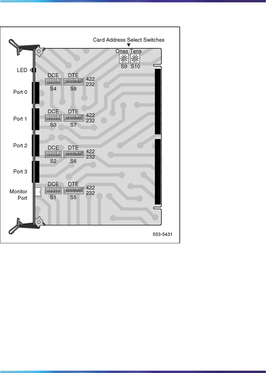
182 ISL installation
Figure 69
MSDL/ISL settings
Shared mode
In shared mode, the D-channel is provided by the DCHI or MSDL card and
PRI. The hardware configuration is basically the same as the ISDN PRI
D-channel. See Figure 70 "ISL in shared mode" (page 183).
Shared mode is established through service change in LD17, prompt USR,
with the response SHA.
In the shared mode, the DCH can share signaling for no more than 382 (T1)
or 480 (E1) trunks, including digital and analog.
Nortel Communication Server 1000
ISDN Primary Rate Interface Installation and Commissioning
NN43001-301 02.03 Standard
Release 5.5 7 December 2007
Copyright © 2003-2007, Nortel Networks
.
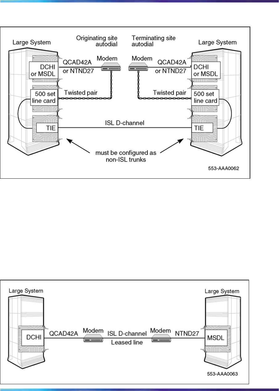
Dedicated mode using leased line 183
Figure 70
ISL in shared mode
Dedicated mode using leased line
In this configuration, the D-channel connects the DCHI or MSDL to a
modem which communicates with a far-end modem over a dedicated leased
line. See Figure 71 "ISL dedicated mode, using leased line" (page 183).A
2400 baud D-channel can support signaling for approximately 382 (T1) or
480 (E1) trunks without non-call associated messages.
Both modems should be set in the synchronous mode.
Figure 71
ISL dedicated mode, using leased line
Nortel Communication Server 1000
ISDN Primary Rate Interface Installation and Commissioning
NN43001-301 02.03 Standard
Release 5.5 7 December 2007
Copyright © 2003-2007, Nortel Networks
.
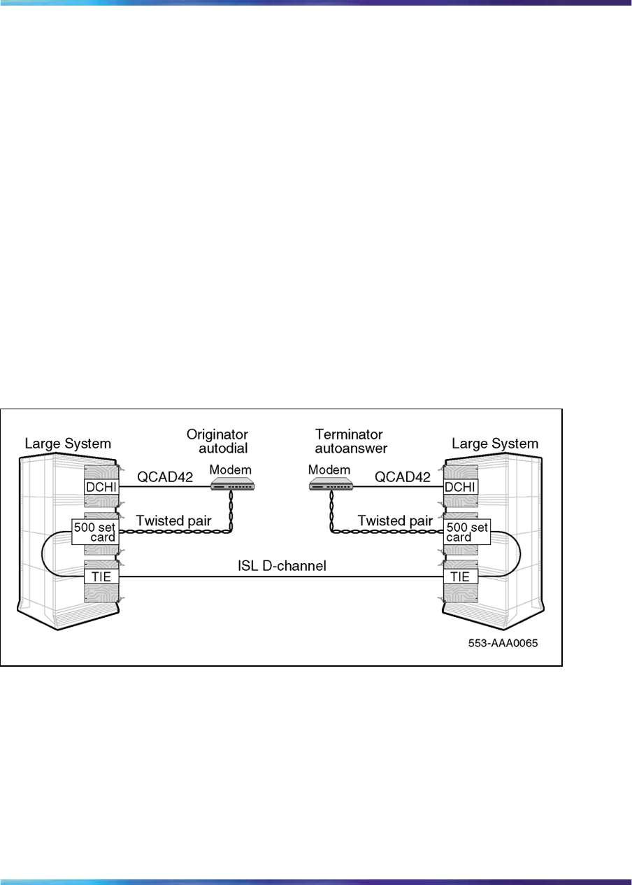
184 ISL installation
Dedicated mode using dialup modem
In this configuration, the DCHI or MSDL is connected to a modem which is
connected to a 500 set line card. See Figure 73 "ISL dedicated mode, using
dialup Hayes Smartmodem 2400" (page 186). The call is connected to the
far end through the analog (500/2500 type set) -to-TIE trunk path.
To set up the D-channel, program the modem at one end in the autodial
mode, so it automatically initiates a call to the other end at power up. The
autodial DN must be coordinated with personnel at the far end switch.
Install a modem for ISL applications
The modem software and hardware must be installed sequentially. The
modem software must be defined before the hardware connection between
the modem and the system can be made. Within the software installation,
either the autodial or the auto-answer software can be set up first. Figure
72 "ISL dedicated mode: using dialup Hayes Smartmodem 2400" (page
184) shows the hardware configuration between two PBXs and their
corresponding modems.
Figure 72
ISL dedicated mode: using dialup Hayes Smartmodem 2400
Examples of parameters used for actual auto-answer and autodial sites are
shown in the following tables (note that the Hayes Smartmodem has been
used.) Table 68 "Active and stored profiles of the autodial or originating
modem" (page 185) shows the active and stored profiles of the autodial site
(or the originating modem). Table 69 "Active and stored profiles of the auto
answer or terminating modem" (page 185) shows the active and stored
profiles of the auto-answer site (or the terminating modem). The Hayes
Smartmodem User Guide contains explanations of the parameters used in
Nortel Communication Server 1000
ISDN Primary Rate Interface Installation and Commissioning
NN43001-301 02.03 Standard
Release 5.5 7 December 2007
Copyright © 2003-2007, Nortel Networks
.

Dedicated mode using dialup modem 185
Table 68 "Active and stored profiles of the autodial or originating modem"
(page 185) and Table 69 "Active and stored profiles of the auto answer
or terminating modem" (page 185).
After the software parameters have been set up, the JP1 jumpers behind
the front faceplate of the Hayes Smartmodem must be dumb strapped on
both modems. Next, see the Hayes Smartmodem Getting Started Guide to
set up the hardware between the system and the modem.
Table 68
Active and stored profiles of the autodial or originating modem
Active profile:
B1 E0 L2 M1 Q1 V1 X4 Y0 &C1 &D0 &G0 &J0 &L0 &P0 &Q2 &R0 &S0 &X0 &Y0
S00:000 S01:000 S02:043 S03:013 S04:010 S05:008 S06:002 S07:030
S08:002 S09:006 S10:014 S12:050 S14:ACH S16:00H S18:000 S21:20H
S22:76H S23:15H S25:005 S26:001 S27:42H
Stored profile 0:
B1 E0 L2 M1 Q1 V1 X4 Y0 &C1 &D0 &G0 &J0 &L0 &P0 &Q2 &R0 &S0 &X0
S00:000 S14:ACH S18:000 S21:20H S22:76H S23:17H S25:005 S26:001
S27:42H
Stored profile 1:
B1 E1 L2 M1 Q0 V1 X4 Y0 &C0 &D0 &G0 &J0 &L0 &P0 &Q0 &R0 &S0 &X0
S00:00 S14:AAH S18:000 S21:00H S22:76H S23:17H S25:005 S26:001
S27:40H
Telephone numbers:
&Z0=ATDT7414011
&Z1=
&Z2=
&Z3=
Table 69
Active and stored profiles of the auto answer or terminating modem
Active profile:
B1 E0 L2 M1 Q1 V1 X4 Y0 &C1 &D2 &G0 &J0 &L0 &P0 &Q1 &R0 &S1 &X2 &Y0
S00:001 S01:000 S02:043 S03:013 S04:010 S05:008 S06:002 S07:030
S08:002 S09:006 S10:014 S12:050 S14:ACH S16:00H S18:000 S21:70H
S22:76H S23:15H S25:005 S26:001 S27:61H
Stored profile 0:
B1 E0 L2 M1 Q1 V1 X4 Y0 &C1 &D2 &G0 &J0 &L0 &P0 &Q1 &R0 &S1 &X2
S00:001 S14:ACH S18:000 S21:70H S22:76H S23:17H S25:005 S26:001
S27:61H
Stored profile 1:
Nortel Communication Server 1000
ISDN Primary Rate Interface Installation and Commissioning
NN43001-301 02.03 Standard
Release 5.5 7 December 2007
Copyright © 2003-2007, Nortel Networks
.
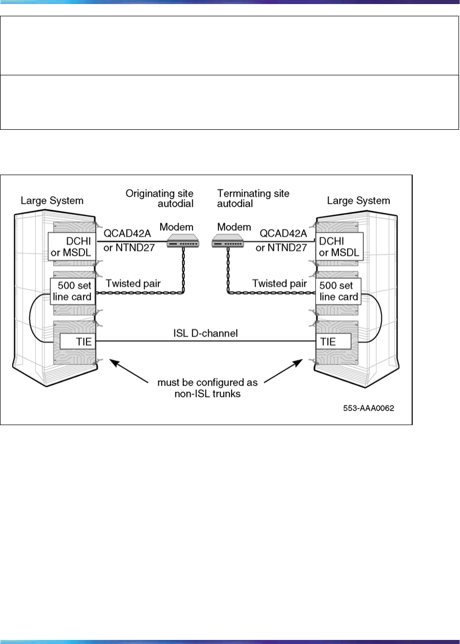
186 ISL installation
B1 E1 L2 M1 Q0 V1 X4 Y0 &C0 &D0 &G0 &J0 &L0 &P0 &Q0 &R0 &S0 &X0
S00:000 S14:AAH S18:000 S21:00H S22:76H S23:17H S25:005 S26:001
S27:40H
Telephone numbers:
&Z0=
&Z1=
&Z2=
&Z3=
Figure 73
ISL dedicated mode, using dialup Hayes Smartmodem 2400
Dedicated mode using PRI/DTI trunks
In this configuration, the DCHI or MSDL is connected to a High Speed Data
Module (HSDM) or Asynchronous/Synchronous Interface Module (ASIM).
See Figure 74 "ISL dedicated mode: using PRI/DTI trunk" (page 187). The
HSDM or ASIM is connected to a Data Line Card (DLC). The call is then
connected to the far end through the DLC to DTI trunk path.
To establish the D-channel in this configuration, set up the HSDM or ASIM
at one end in hot line mode. The hot line DN must be coordinated with
personnel at the far end, then programmed in LD11. The preprogrammed
hot line DN is dialed by the system. If the call cannot be established, the
system continues to dial the hot line number continuously until the call is
connected.
Nortel Communication Server 1000
ISDN Primary Rate Interface Installation and Commissioning
NN43001-301 02.03 Standard
Release 5.5 7 December 2007
Copyright © 2003-2007, Nortel Networks
.
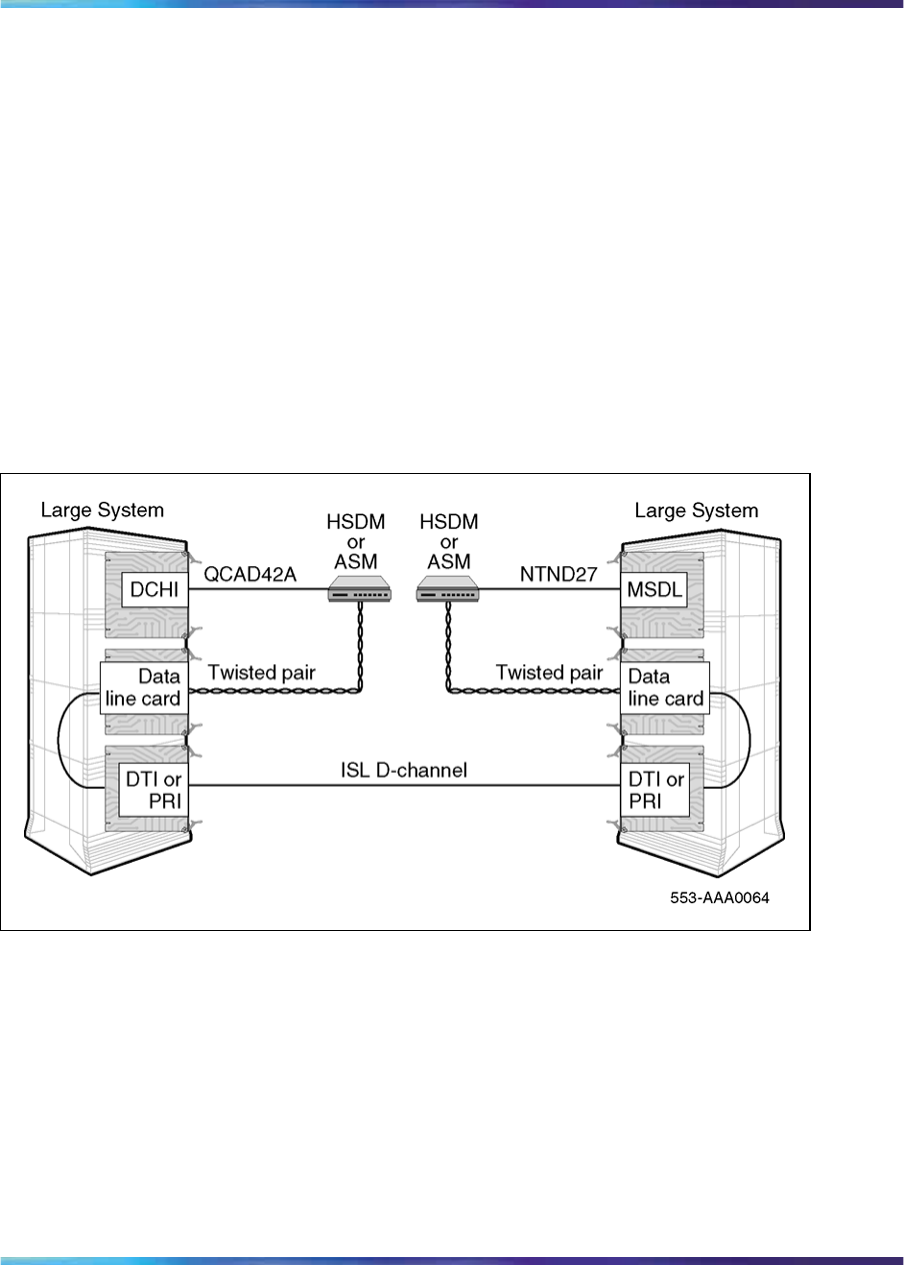
Dedicated mode using dialup modem 187
Set the HSDM or ASIM must be in synchronous mode. A data rate of 9.6
Kbps is recommended because it provides internal error detection and
correction. The following data rates are also supported: 1.2 Kbps, 2.4 Kbps,
3.6 Kbps, 4.8 Kbps, 7.2 Kbps, 14.4 Kbps, 19.2 Kbps, 38.4 Kbps, and 56
Kbps for ASIM. The High Speed Data Module (HSDM) supports 64 Kbps.
Note 1: This configuration is the least reliable due to the lockup
problems inherent in Smart Modems from power splices and noisy lines.
To increase the reliability on this configuration, a constant power source
can be used when powering the modems. Also ensure that the TIE
lines meet data grade specifications.
Note 2: Nortel takes no responsibility for ISL D-channel outages due to
modem lockup.
Figure 74
ISL dedicated mode: using PRI/DTI trunk
QMT11 switch settings
If using the QMT11 ASIM, set the DIP switches, located on top of the unit
under the flip-up, as follows:
•Hotline, On; See Note 1.
•Forced DTR, On; See Note 2.
•FDX (full duplex), On
•SYNC, On
•INTernal CLK, On
Nortel Communication Server 1000
ISDN Primary Rate Interface Installation and Commissioning
NN43001-301 02.03 Standard
Release 5.5 7 December 2007
Copyright © 2003-2007, Nortel Networks
.

188 ISL installation
•Modem/Network, Modem
•Auto Answer, On
•Loopback, Off
Note 1: Set only one side of the interface to originate the hot line.
Note 2: Forced Data Terminal Ready (DTR) automatically reinitiates a
dropped hot line call.
QMT8 switch settings
If the QMT8 Asynchronous Data Module (ADM) is used, set the switches as
follows:
Switch 1: Switch 3: Switch 4:
set to zeros (no VFDN) 1. not used
2. not used
3. FDX (full duplex)
4. modem
5. internal clock
6. no echo
7. auto answer
8. off (no loopback)
1. on
2. on (hot line*)
3. off (DTR-data
terminal
ready-required)
4. on (synchronous)
U5 and U7 must be
jumpered
* Only one side of the
interface should be set to
originate the hot line.
QMT21C switch settings
If using the QMT21 HSDM, set the dip switches, located on top of the unit
under the flip-up, as follows.
•Hotline, On; See Note 1.
•Forced DTR, On; See Note 2.
•FDX (full duplex), On
•SYNC, On
•INTernal CLK, On
•Modem/Network, Modem
•Auto Answer, On
•Loopback, Off
Note 1: Set only one side of the interface to originate the hot line.
Nortel Communication Server 1000
ISDN Primary Rate Interface Installation and Commissioning
NN43001-301 02.03 Standard
Release 5.5 7 December 2007
Copyright © 2003-2007, Nortel Networks
.

ISL installation 189
Note 2: Forced Data Terminal Ready (DTR) automatically reinitiates a
dropped hot line call.
ISL installation
Use Procedure 22 "Install ISL in dedicated mode" (page 189) to install ISL
in dedicated mode. Use Procedure 23 "Install ISL in shared mode" (page
189) to install ISL in shared mode.
Modem paths must have individual configurations: route data blocks, trunks,
and routes.
Install ISL in dedicated mode (digital and analog)
DTI or PRI should already be up and running.
Procedure 22
Install ISL in dedicated mode
Step Action
1In LD17, configure ISL for dedicated mode.
USR = ISLD
ISLM = Number of trunks handled by this D-channel (1-382)
2In LD16, configure the Route Data Block to map out the software
parameters for these trunks.
3Install the modem with leased line functionality.
4In LD14, reassign old trunks to the routes just built in LD16.
5In LD16, out the old DTI route. A separate Route Data Block should
be built for Leased Line, or to accommodate the dialing plan for a
dedicated modem.
—End—
Install ISL in shared mode
DTI or PRI should already be up and running.
Procedure 23
Install ISL in shared mode
Step Action
1In LD14, remove the PRI trunks.
2In LD17, configure ISL for dedicated mode.
Nortel Communication Server 1000
ISDN Primary Rate Interface Installation and Commissioning
NN43001-301 02.03 Standard
Release 5.5 7 December 2007
Copyright © 2003-2007, Nortel Networks
.

190 ISL installation
USR = SHA
ISLM = Number of trunks handled by this D-channel (1-382)
3In LD16, build a PRI route data block. This is the same route you just
removed in step 1.
ISDN = YES
4In LD16 build another route data block to correspond to the IAS
routes.
5In LD14, assign trunks to the newly configured routes.
—End—
Nortel Communication Server 1000
ISDN Primary Rate Interface Installation and Commissioning
NN43001-301 02.03 Standard
Release 5.5 7 December 2007
Copyright © 2003-2007, Nortel Networks
.

191
Echo canceller installation
Contents The section contains information on the following topics:
"Introduction" (page 191)
"Echo canceller operating parameters" (page 191)
"Echo canceller initialization procedures" (page 191)
"PRI to Echo canceller pin assignments" (page 192)
"Electromagnetic Interference" (page 192)
Introduction Echo cancellers are required only in cases where satellite transmission is
being used. The echo canceller detects the length of the loop, and cancels
out transmission reflections (which result in audible echoes of voices on
satellite-carried calls).
Echo canceller operating parameters
The operational parameters of the echo canceller must be:
•Data transfer rate: 4800 baud
•System unit number: 1
•Display timeout: active
•Failures before alarm: 3
Echo canceller initialization procedures
Each of the 24 channels on the echo canceller must be initialized as shown
here:
•Bypass: OFF
•Off-hook: ON
Nortel Communication Server 1000
ISDN Primary Rate Interface Installation and Commissioning
NN43001-301 02.03 Standard
Release 5.5 7 December 2007
Copyright © 2003-2007, Nortel Networks
.

192 Echo canceller installation
•Canceller only: OFF
•H reset: OFF
•H hold: OFF
PRI to Echo canceller pin assignments
The echo canceller is controlled by an RS-232 port on the PRI circuit pack.
The following tables give the echo canceller pin assignments, operating
parameters and initialization procedures.
See Table 70 "PRI-to-Echo canceller - pin assignments" (page 192) for
PRI-to-Echo canceller pin assignments; refer to Figure 75 "PRI to echo
canceller cabling" (page 193) for a PRI-to-Echo-canceller cabling schematic.
Table 70
PRI-to-Echo canceller - pin assignments
Signal PRI pin Echo canceller
pin
EIA RS-232-C
circuit
designator
TXD
(Transmitted Data)
52BA
RXD
(Received Data) 23 BB
RTS
(Request to Send)
—4CC
CTS
(Clear to Send)
—5 CB
Common Return
(signal ground) 10 7AB
DCD
(received line signal detector) 18 CF
DTR
(data terminal ready) 420 CD
Electromagnetic Interference
The Electromagnetic Interference (EMI) filter assembly for PRI is PO643763.
The system meets FCC Part 15, Subpart J, Class A requirements regarding
EMI. In order to accomplish this, the SDI cables must exit the cabinet
through EMI filters on the I/O panel. This procedure depends on the system
cabinet type.
Nortel Communication Server 1000
ISDN Primary Rate Interface Installation and Commissioning
NN43001-301 02.03 Standard
Release 5.5 7 December 2007
Copyright © 2003-2007, Nortel Networks
.

Electromagnetic Interference 193
Figure 75
PRI to echo canceller cabling
Nortel Communication Server 1000
ISDN Primary Rate Interface Installation and Commissioning
NN43001-301 02.03 Standard
Release 5.5 7 December 2007
Copyright © 2003-2007, Nortel Networks
.

194 Echo canceller installation
Nortel Communication Server 1000
ISDN Primary Rate Interface Installation and Commissioning
NN43001-301 02.03 Standard
Release 5.5 7 December 2007
Copyright © 2003-2007, Nortel Networks
.

195
1.5 Mb PRI implementation
Contents This section contains information on the following topics:
"Overview" (page 195)
"Hardware requirements" (page 195)
"Hardware description" (page 196)
"Install PRI hardware" (page 203)
Overview Digital trunks are supported in the Small System cabinet, the IP expansion
cabinet, and the Media Gateway.
This chapter provides the following information required to install PRI on a
system:
•hardware and software installation
•implementation procedures for basic call service
While either the hardware or software can be installed first, the PRI cannot
be enabled and tested until both are completed.
Hardware requirements
Circuit cards
To implement PRI on the system, the hardware shown in Table 71 "Required
circuit cards" (page 195) is required.
Table 71
Required circuit cards
Circuit card Description
NTRB21 DTI/PRI TMDI card.
NTAK09 DTI/PRI circuit card.
Nortel Communication Server 1000
ISDN Primary Rate Interface Installation and Commissioning
NN43001-301 02.03 Standard
Release 5.5 7 December 2007
Copyright © 2003-2007, Nortel Networks
.

196 1.5 Mb PRI implementation
Circuit card Description
NTAK20 Clock-controller daughterboard. Small Systems
supports only one active clock controller per system
or IP expansion cabinet.
Note: Every cabinet/Media Gateway that contains a
digital trunk must contain a clock controller.
NTAK93 D-channel-handler (DCH) interface daughterboard.
NTBK51BA Downloadable D-channel daughterboard (DDCH).
Connects to the NTAK09 DTI/PRI card.
Cables The following cables are required for PRI connections:
•PRI to external T1 cable
•NTBK04 carrier cable
•NT8D97 50-foot extension (if needed)
Channel Service Units (CSU)
When connecting the DTI/PRI to the public network, CSUs are required by
most operating companies. One CSU is required per PRI. Suitable CSUs
which support 64 Kbps clear and Bipolar 8 Zero Substitution (B8ZS) are
available from vendors such as Verilink, Digitalink, Kentrox, and Tellabs.
Note: Contact your Nortel Sales representative for specific local CSU
requirements.
Hardware description
Media Gateway/Media Gateway Expansion
The Media Gateway and Media Gateway Expansion contain physical card
slots, numbered 1 to 10. When configuring the system, the physical card
slot numbers must be transposed to logical card slot numbers. For example,
to configure a card physically located in slot two of the Media Gateway one,
use logical slot 12. To configure a card physically located in slot two of the
Media Gateway two, use logical Slot 22.
Table 72 "Media Gateway and Media Gateway Expansion slot assignments"
(page 197) maps physical card slot numbers to logical card numbers for the
Media Gateway and Media Gateway Expansion and reflects added support
for the Media Gateway and Media Gateway Expansion physical card slot 4.
Nortel Communication Server 1000
ISDN Primary Rate Interface Installation and Commissioning
NN43001-301 02.03 Standard
Release 5.5 7 December 2007
Copyright © 2003-2007, Nortel Networks
.

Hardware description 197
Table 72
Media Gateway and Media Gateway Expansion slot assignments
Media Gateway/Media Gateway Expansion
First Second Third Fourth
Physical
card
slot
Logical
card
slot
Physical
card
slot
Logical
card
slot
Physical
card
slot
Logical
card
slot
Physical
card
slot
Logical
card
slot
1 11 1 21 1 31 1 41
2 12 2 22 2 32 2 42
3 13 3 23 3 33 3 43
4 14 4 24 4 34 4 44
5*5*5*5*
Media
Gateway
6*6*6*6*
717 727 737 747
8 18 8 28 8 38 8 48
9 19 9 29 9 39 9 49
Media
Gateway
Expansion
10 20 10 30 10 40 10 50
Legend
* Not supported.
NTRB21 TMDI card
The NTRB21 TMDI card provides 1.5 MBit/s Digital Trunk Interface or
Primary Rate Interface functionality on the system. The NTRB21 has a
built-in, downloadable D-channel.
The NTRB21can be equipped with the NTAK09 DTI/PRI card (with the
NTBK51 downloadable D-channel daughterboard) and the NTAK93 DCHI
daughterboard.
Note: A TMDI D-channel programmed as a backup D-channel against a
non-TMDI primary D-channel is not supported. Backup D-channels are
supported only when programmed against TMDI primary D-channels.
Figure 76 "NTRB21 TMDI card faceplate" (page 198) shows a faceplate
of the NTRB21 TMDI card.
Shelf slot assignments
For Small Systems, the NTRB21 can be placed in main and expansion
cabinets in any single card slot given in Table 74 "Shelf slot assignments
for NTRB21, NTAK09, and NTAK20" (page 202).
The Media Gateway Expansion does not support digital trunks (DTI/PRI).
Nortel Communication Server 1000
ISDN Primary Rate Interface Installation and Commissioning
NN43001-301 02.03 Standard
Release 5.5 7 December 2007
Copyright © 2003-2007, Nortel Networks
.
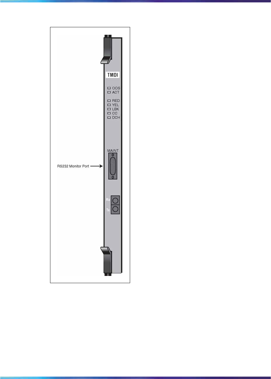
198 1.5 Mb PRI implementation
Figure 76
NTRB21 TMDI card faceplate
NTAK09 DTI/PRI circuit card
The NTAK09 Digital Trunk Interface/Primary Rate Interface (DTI/PRI) card
provides the physical interface for the DS-1 facility T-1 carrier on the
system. It is required for PRI and DTI operation and is also used for ISL
shared-mode applications.
Figure 77 "NTAK09 DTI/PRI circuit card" (page 199) shows the faceplate
layout, the location of the switch and the position of the daughterboards
and connectors.
Nortel Communication Server 1000
ISDN Primary Rate Interface Installation and Commissioning
NN43001-301 02.03 Standard
Release 5.5 7 December 2007
Copyright © 2003-2007, Nortel Networks
.

Hardware description 199
Shelf slot assignments
For cabinet systems, the NTAK09 DTI/PRI card can be placed in main and
expansion cabinets in any single card slot given in Table 74 "Shelf slot
assignments for NTRB21, NTAK09, and NTAK20" (page 202).
Digital trunk cards are not supported in the Media Gateway Expansion.
Figure 77
NTAK09 DTI/PRI circuit card
NTAK20 Clock Controller (CC) daughterboard
Digital Trunking requires synchronized clocking so a shift in one clock source
results in an equivalent shift of the same size and direction in all parts of the
network. Synchronization is accomplished with the NTAK20 clock controller
circuit card in each Main and IP expansion cabinet/Media Gateway.
ATTENTION
IMPORTANT!
Every Small System cabinet or Media Gateway that contains a digital trunk must
contain a clock controller.
If a Small System is equipped with digital trunks, it is recommended that at least
one digital trunk be placed in the main cabinet.
Nortel Communication Server 1000
ISDN Primary Rate Interface Installation and Commissioning
NN43001-301 02.03 Standard
Release 5.5 7 December 2007
Copyright © 2003-2007, Nortel Networks
.

200 1.5 Mb PRI implementation
Note: Clocking slips can occur between systems that are clocked from
different COs, if the COs are not synchronized. The slips can degrade
voice quality.
The Clock Controller circuitry synchronizes the system to an external
reference clock, and generates and distributes the clock to the system. A
Small System can function either as a slave to an external clock or as a
clocking master.
The NTAK20AA version of the clock controller meets AT&T Stratum 3 and
Bell Canada Node Category D specifications. The NTAK20BA version
meets CCITT stratum 4 specifications.
Clocking modes
The system supports a single clock controller that can operate in one of two
modes - tracking or non-tracking (also known as free-run).
Tracking mode In tracking mode, one or possibly two DTI/PRI cards
supply a clock reference to a clock controller daughterboard. One DTI/PRI
is defined as the primary reference source for clock synchronization, while
the other is defined as the secondary reference source (PREF and SREF in
LD 73).
There are two stages to clock controller tracking, as follows:
•tracking a reference
•locked onto a reference
When tracking a reference, the clock controller uses an algorithm to match
its frequency to the frequency of the incoming clock. When the frequencies
are very nearly matched, the clock controller locks onto the reference. The
clock controller makes small adjustments to its own frequency until incoming
and system frequencies correspond.
If the incoming clock reference is stable, the internal clock controller tracks
it, locks onto it, and matches frequencies exactly. Occasionally, however,
environmental circumstances cause the external or internal clocks to drift.
When this happens, the internal clock controller briefly enters the tracking
stage. The green LED flashes momentarily until the clock controller locks
onto the reference once again.
If the incoming reference is unstable, the internal clock controller is
continuously in the tracking stage, with the LED flashing green all the time.
This condition does not present a problem, instead it shows that the clock
controller is continually attempting to lock onto the signal. However, if slips
are occurring, there is a problem with the clock controller or the incoming
line.
Nortel Communication Server 1000
ISDN Primary Rate Interface Installation and Commissioning
NN43001-301 02.03 Standard
Release 5.5 7 December 2007
Copyright © 2003-2007, Nortel Networks
.

Hardware description 201
Free-run (non-tracking) In free-run mode, the clock controller does not
synchronize on any source, it provides its own internal clock to the system.
This mode can be used when the system is used as a master clock source
for other systems in the network. Free-run mode is undesirable if the system
is intended to be a slave. It can occur, however, when both the primary and
secondary clock sources are lost due to hardware faults, or when invoked
by using software commands.
Shelf slot assignment
For cabinet systems, the NTAK09 DTI/PRI card can be placed in main and
expansion cabinets in any single card slot given in Table 74 "Shelf slot
assignments for NTRB21, NTAK09, and NTAK20" (page 202).
Note: For CISPR B group cabinets, the active Clock Controller
(NTAK20) can only occupy slots 1-3, 11-13, 21-23, 31-33, or 41-43 in
an Option 11C cabinet. For FCC and/or CISPR A group cabinets, this
limitation does not exist.
On non-CISPR B system cabinets, the NTAK20 can be placed in slots 1-9 of
the Option 11C main cabinet. On cabinets NTAK11Dx and NTAK11Fx, the
active NTAK20 must be placed in slots 1-3 (slots 4-10 cannot be used.)
On non-CISPR B IP expansion cabinets, the NTAK20 can be placed in slots
11-19, 21-29, 31-39, 41-49 of the first, second, third, and fourth expansion
cabinets, respectively.
Clock controller LED states
The clock controller LED, on the NTAK09 or NTRB21 faceplates, is in
various states depending on the status of the clock controller.
Table 73
Clock controller LEDs
LED Clock controller
On (Red) NTAK20 is equipped and disabled.
On (Green) NTAK20 is equipped and is either locked to a reference
or in free run mode.
Flashing (Green) NTAK20 is equipped and attempting to lock (tracking
mode) to a reference. If the LED flashes continuously
over an extended period of time, check the CC STAT in
LD 60. If the CC is tracking this can be an acceptable
state. Check for slips and related clock controller error
conditions. If none exist, then this state is acceptable,
and the flashing is identifying jitter on the reference.
Off NTAK20 is not equipped.
Nortel Communication Server 1000
ISDN Primary Rate Interface Installation and Commissioning
NN43001-301 02.03 Standard
Release 5.5 7 December 2007
Copyright © 2003-2007, Nortel Networks
.
202 1.5 Mb PRI implementation
Shelf slot assignments for NTRB21, NTAK09 and NTAK20
Table 74 "Shelf slot assignments for NTRB21, NTAK09, and NTAK20"
(page 202) provides the shelf slot assignments for the NTRB21 TMDI card,
NTAK09 DTI/PRI card, and NTAK20 Clock Controller daughterboard in
Small Systems. The NTAK 93 DCH and NTBK51BA DDCH daughterboards
are not included in this table since they are mounted on the NTAK09
DTI/PRI circuit card and not on a shelf.
Table 74
Shelf slot assignments for NTRB21, NTAK09, and NTAK20
NTAK20
Clock controller
daughterboard
NTRB21
TMDI card
NTAK09
DTI/PRI
circuit card CISPR B
cabinets
Non-
CISPR B
cabinets
Main 1–9 1–9 1–3 1–9
(see Note 2)
Expansion 1 11 – 19 11 – 19 11 – 13 11 – 19
Expansion 2 21 – 29 21 – 29 21 – 23 21 – 29
Expansion 3 31 – 39 31 – 39 31 – 33 31 – 39
Small
System
Expansion 4 41 – 49 41 – 49 41 – 43 41 – 49
Note: On cabinets NTAK11Dx and NTAK11Fx, the active card must be
placed in slots 1 – 3 (slots 4 to 10 cannot be used).
NTAK93 D-channel Handler Interface (DCHI) daughterboard
The NTAK93 DCHI daughterboard interfaces with the system Central
Processing Unit (CPU) and mounts on the NTAK09 DTI/PRI circuit card
for PRI or ISL shared mode applications. The DCHI is responsible for
performing the Q.921 layer 2 protocol information. It transfers layer 3
signaling information between two adjacent network switches.
The NTAK93 DCH daughterboard, when installed on the NTAK09 circuit
card, is addressed in the same slot as the NTAK09. The NTAK93 can use
SDI I/O addresses 0 to 79 and port 1.
Note: I/O addresses 0, 1, 2, 8 and 9 are preconfigured on the Small
System and must not conflict with the I/O addresses on the NTAK93
card.
A minimum of one NTAK93 is required for each PRI link. If more than one
PRI link connects to the same end location, a single DCHI circuit card can
support up to a maximum of sixteen PRI connections for the Small System.
Nortel Communication Server 1000
ISDN Primary Rate Interface Installation and Commissioning
NN43001-301 02.03 Standard
Release 5.5 7 December 2007
Copyright © 2003-2007, Nortel Networks
.

Install PRI hardware 203
This allows a total of 382 B-channels or PRI trunks to be supported if a
backup D-channel is also used. A total of 383 B-channels or PRI trunks are
supported if a backup channel is not used.
NTBK51BA Downloadable D-channel (DDCH) daughterboard
The NTBK51BA DDCH daughterboard interfaces with the Small System
Central Processing Unit (CPU) and mounts on the NTAK09 DTI/PRI circuit
card for PRI D-channel applications. The DDCH is equivalent to the MSDL
card used on a Large System, but it only supports D-channel applications
(no SDI or ESDI).
The NTBK51BA DDCH daughterboard, when installed on the NTAK09
circuit card, is addressed in the same slot as the NTAK09.
A minimum of one NTBK51BA is required for each PRI link. If more than
one PRI link connects to the same end location, a single DDCH circuit
card can support up to a maximum of sixteen PRI connections for the
Small Systems. This allows a total of 382 B-channels or PRI trunks to be
supported if a backup D-channel is also used. A total of 383 B-channels or
PRI trunks are supported if a backup channel is not used.
For more information on expansion daughterboards, refer to Communication
Server 1000M and Meridian 1 Small System Planning and Engineering
(NN43011-220).
Install PRI hardware
Install/remove daughterboard on the NTRB21 TMDI card
Work on a flat surface when mounting or removing daughterboards.
Procedure 24
Mounting the NTAK20 daughterboard on the NTRB21
Step Action
1Visually inspect the connector pins on the underside of the
daughterboard. Straighten and realign any bent pins prior to
mounting.
2Place the NTRB21 down flat on an antistatic pad.
3From an overhead view, with the daughterboard parallel above
the NTRB21 and the connector pins aligned over the connector
sockets, line up the mounting holes on the daughterboard (Figure 78
"NTAK20 daughterboard installation on the NTRB21" (page 204))
with the tops of the standoffs on the NTRB21.
Nortel Communication Server 1000
ISDN Primary Rate Interface Installation and Commissioning
NN43001-301 02.03 Standard
Release 5.5 7 December 2007
Copyright © 2003-2007, Nortel Networks
.

204 1.5 Mb PRI implementation
4Slowly lower the daughterboard towards the NTRB21, keeping the
standoffs in line with all four holes, until the holes are resting on the
tops of the four standoffs.
If more than a very slight amount of pressure is required at this point,
the connector pins cannot be aligned with the connector socket. If
so, lift the daughterboard off the NTRB21 and return to step 2.
5Gently apply pressure along the edge of the board where the
connector is located until the standoffs at the two corners adjacent
to the connector snap into a locked position. Then press down on
the two corners on the opposite side until they also lock into place.
Figure 78
NTAK20 daughterboard installation on the NTRB21
—End—
Insert/remove the NTRB21 TMDI card
Refer to Table 74 "Shelf slot assignments for NTRB21, NTAK09, and
NTAK20" (page 202) to determine the slot assignment for the NTRB21
TMDI circuit card appropriate to the system.
Nortel Communication Server 1000
ISDN Primary Rate Interface Installation and Commissioning
NN43001-301 02.03 Standard
Release 5.5 7 December 2007
Copyright © 2003-2007, Nortel Networks
.

Install PRI hardware 205
The NTRB21 card is installed only in the Media Gateway. It is not supported
in the Media Gateway Expansion.
Procedure 25
Inserting the NTRB21 TMDI card
Step Action
1Check for available card slots in the base cabinet and print the
configuration record to determine which slots can be used. To do
this, enter the following command in LD 22:
PRT CFN in LD 22
2If in PRI mode, enter the following command in LD 96 to software
disable the D-channel:
DIS DCH x
where x is the DCH port number that was assigned in LD 17.
3If the Clock Controller is enabled, enter the following command in LD
60 to software disable it:
DIS CC 0
4Hold the NTRB21 by the lock latch, unlock the latch, and slide the
card into the cabinet.
Note: Refer to Table 74 "Shelf slot assignments for NTRB21,
NTAK09, and NTAK20" (page 202) to determine the correct slot
in which to insert the card.
5Enter the following command in LD 96 to enable the TMDI card:
ENL TMDI x ALL
where x is the NTRB21 TMDI card number (DLOP). The card
number associated with an NTRB21 TMDI card is based on the
slot in which the card is installed.
6Within about 30 seconds, the D-channel layer 3 should be
established. To confirm, enter the following command in LD 96 to
request the current status of the D-channel:
STAT DCH (N)
The system response is:
DCH N EST OPER
This means that the D-channel is established and operational.
—End—
Nortel Communication Server 1000
ISDN Primary Rate Interface Installation and Commissioning
NN43001-301 02.03 Standard
Release 5.5 7 December 2007
Copyright © 2003-2007, Nortel Networks
.

206 1.5 Mb PRI implementation
Procedure 26
Removing the NTRB21 TMDI card
Step Action
1If in PRI mode, enter the following command in LD 96 to software
disable the D-channel:
DIS DCH x
where x is the DCH port number that was assigned in LD 17.
2If the Clock Controller is enabled, enter the following command in LD
60 to software disable it:
DIS CC 0
3Enter the following command in LD 96 to disable the NTRB21 TMDI
card:
DIS TMDI x All
where x is the NTRB21 TMDI card number (DLOP). The card
number associated with a NTRB21 TMDI card is based on the slot in
which the card is installed.
4Hold the NTRB21 by the lock latch, unlock the latch, and slide the
card out from the cabinet.
—End—
Install/remove daughterboards on the NTAK09 DTI/PRI card
Use these guidelines to mount the NTAK20 CC and the NTAK93 DCHI or
NTBK51 DDCH daughterboards on the NTAK09 DTI/PRI card. Because
of the physical layout of the mother and daughterboards, the NTAK93 or
NTBK51 should be mounted before the NTAK20. Work on a flat surface
when mounting or removing daughterboards.
Procedure 27
Mounting the daughterboards on the NTAK09
Step Action
1Visually inspect the connector pins on the underside of the
daughterboard. Straighten and realign any bent pins prior to
mounting.
2Place the NTAK09 down flat on an antistatic pad.
3From an overhead view, with the daughterboard parallel above
the NTAK09 and the connector pins aligned over the connector
Nortel Communication Server 1000
ISDN Primary Rate Interface Installation and Commissioning
NN43001-301 02.03 Standard
Release 5.5 7 December 2007
Copyright © 2003-2007, Nortel Networks
.

Install PRI hardware 207
sockets, align the mounting holes on the daughterboard (Figure 79
"Daughterboard installation on the NTAK09" (page 208)) with the
tops of the standoffs on the NTAK09.
4Slowly lower the daughterboard toward the NTAK09, keeping the
standoffs in line with all four holes, until the holes rest on top of the
four standoffs.
Note: If more than a very slight amount of pressure is required at
this point, the connector pins are not aligned with the connector
socket. If so, lift the daughterboard off the NTAK09 and return
to step 2.
5Gently apply pressure along the edge of the board where the
connector is located until the standoffs at the two corners adjacent to
the connector snap into a locked position. Then press down on the
two corners on the opposite side until they also are locked into place.
—End—
Use these guidelines to remove the NTAK20 Clock Controller (CC) and the
NTAK93 DCHI or NTBK51 DDCH daughterboards from the NTAK09 DTI/PRI
card. Because of the physical layout of the mother and daughterboards, the
NTAK20 should be removed before the NTAK93 or NTBK51.
Procedure 28
Removing the daughterboards from the NTAK09
Step Action
1Starting at the two corners opposite the connector, gently lift each
corner out of the locking groove of the standoff.
2At the two corners adjacent to the connector, gently lift the entire
side until the mounting holes are clear of the locking groove of the
standoff.
3To remove the connector pins, grasp the edge of the board adjacent
to the connector and lift gently.
If more than one NTAK09 card is installed, the additional cards might
not carry daughterboards, depending on the system configuration.
At least one NTAK20 (per system) is always required.
—End—
Nortel Communication Server 1000
ISDN Primary Rate Interface Installation and Commissioning
NN43001-301 02.03 Standard
Release 5.5 7 December 2007
Copyright © 2003-2007, Nortel Networks
.
208 1.5 Mb PRI implementation
Figure 79
Daughterboard installation on the NTAK09
Set switches on NTAK09 DTI/PRI card
Set the switches on the NTAK09 DTI/PRI card according to Table 75
"NTAK09 switch settings" (page 208).
Table 75
NTAK09 switch settings
Distance to digital
cross connect 1
DCH F/W 2
(LEN 0) 3
(LEN 1) 4
(LEN 2)
0 - 133 feet Off Off Off On
133 - 266 feet Off On On Off
266 - 399 feet Off Off On Off
399 - 533 feet Off On Off Off
533 - 655 feet Off Off Off Off
Nortel Communication Server 1000
ISDN Primary Rate Interface Installation and Commissioning
NN43001-301 02.03 Standard
Release 5.5 7 December 2007
Copyright © 2003-2007, Nortel Networks
.

Install PRI hardware 209
Installing the NTAK09
Refer to Table 74 "Shelf slot assignments for NTRB21, NTAK09, and
NTAK20" (page 202) to determine the slot assignment for the NTAK09
DTI/PRI circuit card appropriate to the system.
The NTAK09 DTI/PRI card is installed only in the Media Gateway. It is not
supported in the Media Gateway Expansion.
Procedure 29
Installing the NTAK09
Step Action
1Check for available card slots in the base and expansion cabinets,
and Media Gateway systems and print the configuration record to
determine which slots can be used. To do this, enter the following
command in LD 22:
PRT CFN
2Hold the NTAK09 by the lock latch, unlock the latch, and slide the
card into the cabinet.
Note: Refer to Table 74 "Shelf slot assignments for NTRB21,
NTAK09, and NTAK20" (page 202) to determine the correct slot
in which to insert the card.
—End—
The only cable required to support the NTAK09 DTI/PRI circuit card is the
NTBK04 cable. The cable is twenty feet long. If additional distance is
required, the NT8D97AX fifty-foot extension is available up to a 600 foot
maximum. Table 76 "DS-1 line interface pinout for NTBK04 cable" (page
210) gives pinout information for the NTBK04.
Procedure 30
Connecting the cables
Step Action
1Connect the NTBK04 cable to a 50-pin Amphenol connector on the
cabinet.
For a Small System, the Amphenol connector is located below the
card slot in which the NTAK09 circuit card is installed.
2Connect the other end of the cable to the CSU or DSX-1 cross
connect.
Nortel Communication Server 1000
ISDN Primary Rate Interface Installation and Commissioning
NN43001-301 02.03 Standard
Release 5.5 7 December 2007
Copyright © 2003-2007, Nortel Networks
.

210 1.5 Mb PRI implementation
Table 76
DS-1 line interface pinout for NTBK04 cable
From 50-pin
MDF connector To DB-15 Signal
name Description
pin 48 pin 1 T transmit tip to
network
pin 23 pin 9 R transmit ring to
network
pin 25 pin 2 FGND frame ground
pin 49 pin 3 T1 receive tip from
network
pin 24 pin 11 R1 receive ring from
network
—End—
Procedure 31
Enabling the NTRB21 TMDI card
Step Action
1Enter the following command in LD 96 to enable the NTRB21 TMDI
card:
ENL TMDI x ALL
where x is the NTRB21 TMDI card number (DLOP). The card
number associated with a NTRB21 TMDI card is based on the slot in
which the card is installed.
2If in PRI mode, enter the following command in LD 96 to software
enable the D-channel:
ENL DCH y
where y is the DCH port number that was assigned in LD 17.
3Within about 30 seconds, the D-channel layer 3 should be
established. To confirm, enter the following command in LD 60 to
request the current status of the D-channel:
STAT DCH (N)
The system response is:
DCH N EST OPER
This means that the D-channel is established and operational.
Nortel Communication Server 1000
ISDN Primary Rate Interface Installation and Commissioning
NN43001-301 02.03 Standard
Release 5.5 7 December 2007
Copyright © 2003-2007, Nortel Networks
.

Install PRI hardware 211
—End—
Procedure 32
Enabling the NTAK09 DTI/PRI card
Step Action
The DCHI and PRI cards must be configured prior to software enabling the
NTAK09. Refer to the procedure Procedure 33 "Implementing basic PRI"
(page 212) for further information.
1Enter the following command in LD 60 to software enable all NTAK09
DTI/PRI cards:
ENLL C
where C is the DTI/PRI card number (DLOP). The card number
associated with a DTI/PRI card is based on the slot in which the
card is installed.
Under normal conditions, this step enables the clock controller and
D-channel interface. If enable fails, enter the following command in
LD 60 to software enable clock tracking on the primary digital card:
ENL CC 0
2Enter the following command in LD 96 to software enable the
NTAK93 (DCHI) daughterboard:
ENL DCHI N
where N is the DCHI I/O address.
3Within about 30 seconds, the D-channel layer 3 should be
established. To confirm, enter the following command in LD 60 to
request the current status of the D-channel:
STAT DCH (N)
The system response is:
DCH N EST OPER
This means that the D-channel is established and operational.
—End—
Use this procedure to configure the PRI cards, DCHI interface, DCH link and
ISDN trunk route and trunks (B-channels) that are required to implement
PRI between systems. No feature applications other than Basic Call Service
are included in the implementation.
Nortel Communication Server 1000
ISDN Primary Rate Interface Installation and Commissioning
NN43001-301 02.03 Standard
Release 5.5 7 December 2007
Copyright © 2003-2007, Nortel Networks
.

212 1.5 Mb PRI implementation
PRI cards must be configured before defining the DCH links or PRI
applications.
Prompts which do not show a response can be left as default. For more
information on any of these prompts, refer to Software Input Output
Administration (NN43001-611).
Before installing PRI cards in an IP expansion cabinet/Media Gateway,
first configure the expansion cabinet/Media Gateway for IP connectivity.
Refer to LD 117 in the Software Input Output Reference — Maintenance
(NN43001-711) for further information.
To implement PRI on the system:
Procedure 33
Implementing basic PRI
Step Action
1Add a PRI card. step 6
2Add a DCHI card. "LD 17 - Adding a PRI card" (page 212)
3Define a PRI customer. "LD 15 - Defining a PRI customer" (page
214)
4Define a PRI service route. "LD 16 - Configuring an ISDN service
route" (page 215)
5Define service channels (B-channels) and PRI trunks. "LD 14 -
Defining service channels and PRI trunks" (page 216)
6Define clock synchronization. "LD 73 - Defining system timers and
clock controller parameters" (page 217)
—End—
LD 17 - Adding a PRI card
Prompt Response Description
REQ CHG Change existing data.
TYPE CFN Configuration data block.
CEQU YES Changes to common equipment.
PRI loop x card x For Large Systems and Small Systems
TMDI (Yes)
No TMDI Card (Mode set to PRI OR TRK) Option 11C Cabinet Other card
Nortel Communication Server 1000
ISDN Primary Rate Interface Installation and Commissioning
NN43001-301 02.03 Standard
Release 5.5 7 December 2007
Copyright © 2003-2007, Nortel Networks
.

Install PRI hardware 213
LD 17 - Adding a D-channel interface
Prompt Response Description
REQ CHG Change existing data.
TYPE ADAN Action Device And Number.
- ADAN NEW DCH xx
CHG DCH xx
OUT DCH xx
Add a primary D-channel (any unused SDI port.)
Change a primary D-channel.
Remove the primary D-channel, where:
xx =0-79.
- CTYP DCHI
MSDL
TMDI
DCHI = D-channel configuration for the NTAK09 card or
NTAK93.
MSDL = NTBK51 Downloadable D-channel daughterboard.
TMDI = D-channel configuration on TMDI (NTRB21) card.
- CDNO 1-50 Card slot number to be used as the primary DDCH/DCHI.
Card slots 10, 20, 30, 40, and 50 are only applicable for
D-channel configuration of ISL or VNS.
- PORT 1PORT must be set to 1.
- DES <CR> Designator.
- USR PRI D-channel is for ISDN PRI only.
- IFC xx Interface type.
- - DCHL xx PRI loop number.
- OTBF 1-(16)-127 Number of output request buffers.
Note: For a single PRI link, leave this prompt at default (16).
Add 5 output request buffers per additional link.
- DRAT 64KC D-channel transmission rate.
- SIDE NET (USR) Prompted only if IFC is set to SL1.
NET = network, the controlling switch.
USR = slave to the controller.
- RLS xx Release ID of the switch at the far-end of the D-channel.
- RCAP ND2 Remote capability.
- OVLR YES (NO) Allow or disallow overlap receiving on a D-channel. Default
is NO. Enter carriage return if settings are to be left at
default.
Nortel Communication Server 1000
ISDN Primary Rate Interface Installation and Commissioning
NN43001-301 02.03 Standard
Release 5.5 7 December 2007
Copyright © 2003-2007, Nortel Networks
.

214 1.5 Mb PRI implementation
Prompt Response Description
- LAPD YES (NO) Change LAPD parameters. Enter carriage return if timers
are to be left at default. The following timers are prompted
only if LAPD is set to YES. (They can all be left at default
during initial setup.)
- - T23 1-(20)-31 Interface guard timer checks how long the interface takes to
respond. In units of 0.5 seconds (default 20 = 10 seconds).
- - T200 2-(3)-40 Retransmission timer in units of 0.5 seconds (default 3 =
1.5 seconds).
- - N200 1-(3)-8 Maximum number of retransmissions.
- - N201 4(260) Maximum number of octets in information field.
- - K 1-(7)-32 Maximum number of outstanding unacknowledged frames
(NAKS).
LD 15 - Defining a PRI customer
Prompt Response Description
REQ: NEW
CHG Add new data.
Change existing data.
TYPE: NET Networking Data.
CUST 0-99 Customer number
Range for Large System, Call Server 1000E, and Media
Gateway 1000E
0-31 Range for Small System, Media Gateway 1000B
LDN0 xxxx Listed Directory number 0 must be defined for ISDN PRI
DID service.
The length of LDN0 determines the number of trailing digits
translated as the dialed DN on PRI DID routes.
Up to seven digits can be entered if DNXP option 150 is
equipped. Otherwise, up to four digits can be entered.
AC2
NPA
NXX
INTL
SPN
LOC
ESN Access Code 2. Enter incoming ISDN call types
(NARS network translation types) for which AC2 must be
inserted when INAC = YES in LD 16.
Multiple responses are allowed. Prompted only if NARS
is equipped. If a NARS call type is not entered here, it is
defaulted to AC1.
E.164 National.
E.164 Subscriber.
International.
Nortel Communication Server 1000
ISDN Primary Rate Interface Installation and Commissioning
NN43001-301 02.03 Standard
Release 5.5 7 December 2007
Copyright © 2003-2007, Nortel Networks
.

Install PRI hardware 215
Prompt Response Description
Special Number.
Location Code
ISDN YES Customer is equipped with ISDN.
- PNI (0) 1-32700 Private Network Identifier. Each customer data block must
have a unique PNI when multi-customer option is equipped.
PNI = 1 is typical for CUST = 0. It must be matched by
the PNI in the far-end RDB.
Note: Using the default value of PNI = 0 prevents operation
of features like NRAG, NACD and NMS.
- HNPA NPA Telephone area code for this system. Sent as part of setup
message as calling line identification.
- HNXX NXX Telephone local exchange code for this system. Sent as
part of setup message as calling line identification.
- - HLOC XXX Home location code (NARS), prompted when PRA = YES.
- - LSC 1-9999 One to four digit Local Steering Code, if required in the
Coordinated Dialing Plan (CDP). LSCs are required only if
the CDP DNs are longer than the local PDNs.
The CLID sent for a CDP call is composed of the LSC
defined in LD 15 plus the PDN of the calling set. Various
ISDN network features depend on the CLID as the "return
address" for sending feature control messages.
Multiple LSCs can be defined in LD 87 for CDP, but only
one LSC can be defined here for CLID.
LD 16 - Configuring an ISDN service route
Prompt Response Description
REQ NEW
CHG Add new data.
Change existing data.
TYPE RDB Route data block.
TKTP xxx Trunk type.
DTRK YES Digital trunk route.
- DGTP PRI 1.5 Mb PRI. Prompted only if PRA = YES in LD15.
ISDN YES ISDN option.
- MODE PRA Route used for PRA only.
Nortel Communication Server 1000
ISDN Primary Rate Interface Installation and Commissioning
NN43001-301 02.03 Standard
Release 5.5 7 December 2007
Copyright © 2003-2007, Nortel Networks
.

216 1.5 Mb PRI implementation
Prompt Response Description
- - PNI (0) 1-32700 Private Network Identifier. Each customer data block must
have a unique PNI when multi-customer option is equipped.
PNI = 1 is typical for CUST = 0. It must be matched by
the PNI in the far-end RDB.
Note: Using the default value of PNI = 0, prevents operation
of features like NRAG, NACD and NMS.
IFC xx Interface type.
- CHTY BCH Signalling type - prompted if DTRK is YES. D-channel
signalling for B-channels.
- CTYP <CR> Call Type. Enter the call type to be associated with the
outgoing route for direct dialing using the trunk access
code (instead of NARS access code).
See the Software Input Output Administration
(NN43001-611) for a listing of possible responses.
- INAC YES Insert ESN Access Code based on NARS/BARS call
type for incoming calls on TIE routes only. If NARS is
equipped, this feature inserts AC1 or AC2, depending on
the responses to AC2 in LD 15 Customer Data Block.
For NARS/BARS call types, INAC bypasses incoming digit
insertion specified by INST in LD 16 Route Data Block.
Unknown call types, including CDP steering codes, are
not affected by INAC, and do not bypass digit insertion
specified by INST.
INAC must be set to YES to support features such as
Network ACD and Network Message Services, which
depend on non-call associated TCAP facility messages.
LD 14 - Defining service channels and PRI trunks
Prompt Response Description
REQ NEW
CHG Add new data.
Change existing data.
When assigning several members at once use the multiple
create command NEW XX.
TYPE TIE TIE Trunk only, allowed between MSL-1.
TN l ch Loop and channel for digital trunks
Nortel Communication Server 1000
ISDN Primary Rate Interface Installation and Commissioning
NN43001-301 02.03 Standard
Release 5.5 7 December 2007
Copyright © 2003-2007, Nortel Networks
.

Install PRI hardware 217
Prompt Response Description
RTMB 0-511 1-510 Route number and Member number
Range for Large System and CS 1000E system.
0-127 1-4000 Range for Meridian 1 Small System, Media Gateway 1000B.
LD 73 - Defining system timers and clock controller parameters
Prompt Response Description
REQ CHG Change existing data.
TYPE PRI 1.5 Mb PRI.
FEAT SYTI System timers.
CCO xx Card slot number for Clock Controller 0.
PREF CCO xx Card number of PRI/DTI/SILC containing the primary clock
reference for the main cabinet
SREF CCO xx Card number of PRI/DTI/SILC containing the primary clock
reference for the main cabinet
CC1 xx Card number for Clock Controller 1.
PREF CC1 xx Primary Reference DTI/PRI loop for Clock controller one.
SREF CC1 xx Secondary Reference DTI/PRI loop for Clock controller
one.
CC2 xx Card number for Clock Controller 2.
PREF CC2 xx Card number of PRI/DTI/SILC or DTI2/PRI2/SILC
containing the primary clock reference.
SREF CC2 xx Card number of PRI/DTI/SILC or DTI2/PRI2/SILC
containing the primary clock reference.
CC3 xx Card number for Clock Controller 3.
PREF CC3 xx Card number of PRI/DTI/SILC or DTI2/PRI2/SILC
containing the primary clock reference.
SREF CC3 xx Card number of PRI/DTI/SILC or DTI2/PRI2/SILC
containing the primary clock reference.
CC4 xx Card number for Clock Controller 4.
PREF CC4 xx Card number of PRI/DTI/SILC or DTI2/PRI2/SILC
containing the primary clock reference.
SREF CC4 xx Card number of PRI/DTI/SILC or DTI2/PRI2/SILC
containing the primary clock reference.
CCAR 0-(15) Clock Controller Audit Rate.
Enter the time (in minutes) between normal CC audits.
Nortel Communication Server 1000
ISDN Primary Rate Interface Installation and Commissioning
NN43001-301 02.03 Standard
Release 5.5 7 December 2007
Copyright © 2003-2007, Nortel Networks
.

218 1.5 Mb PRI implementation
Nortel Communication Server 1000
ISDN Primary Rate Interface Installation and Commissioning
NN43001-301 02.03 Standard
Release 5.5 7 December 2007
Copyright © 2003-2007, Nortel Networks
.

219
1.5 Mb DTI implementation
Contents This section contains information on the following topics:
"Overview" (page 219)
"Hardware requirements" (page 219)
"Hardware description" (page 196)
"Install DTI hardware" (page 220)
"Software enable the DTI/PRI cards" (page 222)
Overview This chapter provides the information required to install DTI on a system,
including:
•hardware and software installation
•implementation procedures for basic call service
This chapter covers the most common type of Nortel DTI installation – a
24-channel Digital Trunk Interface (DTI) installation between two systems,
or between a system and a central office.
Digital trunks are supported in Small System IP expansion cabinets.
Hardware requirements
To implement DTI on the system, the hardware listed in Table 77 "DTI
hardware" (page 219) is required:
Table 77
DTI hardware
Item Description
NTRB21 DTI/PRI TMDI card
Nortel Communication Server 1000
ISDN Primary Rate Interface Installation and Commissioning
NN43001-301 02.03 Standard
Release 5.5 7 December 2007
Copyright © 2003-2007, Nortel Networks
.

220 1.5 Mb DTI implementation
Item Description
NTAK09 DTI/PRI Circuit card
NTAK20 Clock Controller Daughter board.
Option 11C Cabinet support only one active Clock
Controller per IP Expansion cabinet.
NTBK04 Carrier Cable
Cables The following cables are required for DTI connections:
•DTI to external T1 cable
•NTBK04 carrier cable
•NT8D97 50-foot extension (if needed)
Channel Service Units (CSU)
When connecting the DTI/PRI to the public network, Channel Service Units
(CSUs) are required by most operating companies. One CSU is required
per DTI. Suitable CSUs which support 64 Kbps clear and Bipolar 8 Zero
Substitution (B8ZS) are available from vendors such as Verilink, Digitalink,
Kentrox and Tellabs.
Contact your Nortel Sales representative for specific local CSU
requirements.
Hardware description
Refer to "Hardware description" (page 196).
Install DTI hardware
Refer to ""Install PRI hardware" (page 203)" for information on installing
DTI hardware. Specifically:
•To install the NTRB21 DTI/PRI card, see "Insert/remove the NTRB21
TMDI card" (page 204).
•To install the NTAK09 DTI/PRI card, see "Installing the NTAK09" (page
209).
•To install the NTAK20 Clock Controller, see "Install/remove
daughterboards on the NTAK09 DTI/PRI card" (page 206).
Set the switches
Set the switches on the NTAK09 DTI/PRI card according to Table 78
"NTAK09 switch settings" (page 221).
Nortel Communication Server 1000
ISDN Primary Rate Interface Installation and Commissioning
NN43001-301 02.03 Standard
Release 5.5 7 December 2007
Copyright © 2003-2007, Nortel Networks
.
Install DTI hardware 221
Table 78
NTAK09 switch settings
Distance to digital
crossconnect 1
DCH F/W 2
(LEN 0) 3
(LEN 1) 4
(LEN 2)
0 - 133 feet Off Off Off On
133 - 266 feet Off On On Off
266 - 399 feet Off Off On Off
399 - 533 feet Off On Off Off
533 - 655 feet Off Off Off Off
Connect the cables
For Small Systems, connect the NTBK04 cable to the 50-pin amphenol
connector below the card slot in which the NTAK09 circuit card is installed.
Connect the other end of the cable to the CSU or DSX-1 cross connect.
The NTBK04 is twenty feet long. If additional distance is required, the
NT8D97AX 50-foot extension is available up to a 600-foot maximum. The
only cable required to support the NTAK09 circuit card is the NTBK04.
Pinout information on the NTBK04 cable is given in Table 79 "DS-1 line
interface pinout for NTBK04 cable" (page 221).
Table 79
DS-1 line interface pinout for NTBK04 cable
From 50-pin
MDF connector to DB-15 Signal
name Description
pin 48 pin 1 T transmit tip to network
pin 23 pin 9 R transmit ring to
network
pin 25 pin 2 FGND frame ground
pin 49 pin 3 T1 receive tip from
network
pin 24 pin 11 R1 receive ring from
network
Nortel Communication Server 1000
ISDN Primary Rate Interface Installation and Commissioning
NN43001-301 02.03 Standard
Release 5.5 7 December 2007
Copyright © 2003-2007, Nortel Networks
.

222 1.5 Mb DTI implementation
Software enable the DTI/PRI cards
Procedure 34
Enabling the NTRB21 TMDI card
Step Action
1Enter the following command in LD 96 to enable the NTRB21 TMDI
card:
ENL TMDI x ALL
where
xis the NTRB21 TMDI card number (DLOP). The card number
associated with a NTRB21 TMDI card is based on the slot in
which the card is installed.
2If in DTI mode, enter the following command in LD 96 to software
enable the D-channel:
ENL DCH y
where
yis the DCH port number that was assigned in LD 17.
3Within about 30 seconds, the D-channel layer 3 should be
established. To confirm, enter the following command in LD 60 to
request the current status of the D-channel:
STAT DCH (N)
The system response is:
DCH N EST OPER
This means that the D-channel is established and operational.
—End—
The DCHI and DTI cards must be implemented prior to software enabling
the NTAK09. Refer to the section Procedure 33 "Implementing basic PRI"
(page 212) for further information.
Procedure 35
Enabling the NTAK09 card
Step Action
1Enter the following command in LD 60 to software enable all NTAK09
DTI/PRI cards:
Nortel Communication Server 1000
ISDN Primary Rate Interface Installation and Commissioning
NN43001-301 02.03 Standard
Release 5.5 7 December 2007
Copyright © 2003-2007, Nortel Networks
.

Software enable the DTI/PRI cards 223
ENLL C
where
Cis the DTI/PRI card number (DLOP). The card number
associated with a DTI/PRI card is based on the slot in which the
card is installed.
Under normal conditions, this step enables the clock controller and
D-channel interface. If enable fails, go to step 2.
2Optional: Enter the following command in LD 60 to enable clock
tracking on the primary digital card:
ENL CC 0
3Enter the following command in LD 96 to software enable the
NTAK93 (DCHI) daughterboard:
ENL DCHI N
where
Nis the DCHI I/O address.
4Within about 30 seconds, the D-channel layer 3 should be
established. To confirm, enter the following command in LD 60 to
request the current status of the D-channel:
STAT DCH (N)
The system response is:
DCH N EST OPER
This means that the D-channel is established and operational.
—End—
Use this procedure to implement the DTI software interface between
systems or between a system and a central office.
Procedure 36
Implementing DTI
Step Action
1Add a DTI card. See "LD 17 - Adding a DTI card" (page 224).
2Configure a DTI trunk route. See "LD 16 - Configuring a DTI trunk
route" (page 224).
3Configure the trunks. See "LD 14 - Configuring the trunks" (page
225).
Nortel Communication Server 1000
ISDN Primary Rate Interface Installation and Commissioning
NN43001-301 02.03 Standard
Release 5.5 7 December 2007
Copyright © 2003-2007, Nortel Networks
.

224 1.5 Mb DTI implementation
4Assign clock’s reference source. See "LD 73 - Assigning a clock
reference source" (page 225).
—End—
LD 17 - Adding a DTI card
Prompt Response Description
REQ CHG Change existing data.
TYPE CFN Configuration data block.
...
PARM YES
...
PCML (MU) A System PCM law.
Default is MU law.
...
CEQU YES Changes to common equipment.
DLOP ll dd ff Digital Trunk Interface Loop or Loops
MODE TRK Select Digital Trunk Interface mode.
TMDI (YES) NO Whether the card is a TMDI card.
YALM DG2 (FDL) Yellow alarm method — prompted only if the frame format
is ESF — Must match the far end.
Use FDL with ESF and use DG2 with non-ESF. If not
prompted then DG2 is set automatically.
TRSH 0-15 The maintenance and threshold table to be used for this
DTI card, as configured in LD 73.
T1TE 012 T1 Transmit Equalization (0=0-200 ft., 1=200-400 ft,
2=400-700 ft). Only for TMDI = YES.
LD 16 - Configuring a DTI trunk route
Prompt Response Description
REQ NEW
CHG Add new data.
Change existing data.
TYPE RDB Route data block.
TKTP Create a trunk route.
Nortel Communication Server 1000
ISDN Primary Rate Interface Installation and Commissioning
NN43001-301 02.03 Standard
Release 5.5 7 December 2007
Copyright © 2003-2007, Nortel Networks
.

Software enable the DTI/PRI cards 225
Prompt Response Description
COT
WAT
DID
TIE
FEX
Central Office Trunk data block WATS Trunk data block
Direct Inward Dial Trunk data block TIE Trunk data block
Foreign Exchange
DTRK YES Digital trunk route.
LD 14 - Configuring the trunks
Prompt Response Description
REQ NEW
CHG Add new data.
Change existing data.
TYPE xxx Trunk type
TN l ch Loop and channel for digital trunks
RTMB 0-511 1-4000 Route number and Member number
Range for Large System and CS 1000E system.
0-127 1-4000 Range for Meridian 1 Small System, Media Gateway
1000B.
LD 73 - Assigning a clock reference source
Prompt Response Description
REQ CHG Change existing data.
TYPE DDB Digital Data Block.
CCO xx Card slot number for Clock Controller 0.
PREF CCO xx Card number of PRI/DTI/SILC containing the primary clock
reference for the main cabinet
SREF CCO xx Card number of PRI/DTI/SILC containing the primary clock
reference for the main cabinet
CC1 xx Card number for Clock Controller 1.
PREF CC1 xx Primary Reference DTI/PRI loop for Clock controller one.
SREF CC1 xx Primary Reference DTI/PRI loop for Clock controller one.
CC2 xx Card number for Clock Controller 2.
PREF CC2 xx Card number of PRI/DTI/SILC or DTI2/PRI2/SILC
containing the primary clock reference.
SREF CC2 xx Card number of PRI/DTI/SILC or DTI2/PRI2/SILC
containing the primary clock reference.
CC3 xx Card number for Clock Controller 3.
PREF CC3 xx Card number of PRI/DTI/SILC or DTI2/PRI2/SILC
containing the primary clock reference.
Nortel Communication Server 1000
ISDN Primary Rate Interface Installation and Commissioning
NN43001-301 02.03 Standard
Release 5.5 7 December 2007
Copyright © 2003-2007, Nortel Networks
.

226 1.5 Mb DTI implementation
Prompt Response Description
SREF CC3 xx Card number of PRI/DTI/SILC or DTI2/PRI2/SILC
containing the primary clock reference.
CC4 xx Card number for Clock Controller 4.
PREF CC4 xx Card number of PRI/DTI/SILC or DTI2/PRI2/SILC
containing the primary clock reference.
SREF CC4 xx Card number of PRI/DTI/SILC or DTI2/PRI2/SILC
containing the primary clock reference.
Nortel Communication Server 1000
ISDN Primary Rate Interface Installation and Commissioning
NN43001-301 02.03 Standard
Release 5.5 7 December 2007
Copyright © 2003-2007, Nortel Networks
.

227
1.5 Mb ISL implementation
Contents This section contains information on the following topics:
"Overview" (page 227)
"Hardware requirements" (page 227)
"Basic ISL implementation" (page 232)
Overview This chapter contains the information required to implement ISL on the
system. It describes:
•hardware and software installation
•hardware and software configuration for basic call service
Two modes of ISL are available: shared and dedicated. This chapter covers
the most common type of Nortel ISL installation, an ISDN Signaling Link
(ISL) installation in dedicated mode using dedicated and leased lines.
Hardware requirements
To implement ISL regardless of operation mode, analog or digital TIE lines
are used as B-channels:
•NT8D15 or NT8D14 Analog TIE Trunk cards
•NTAK09 Digital trunk cards (for shared mode)
•NTAK02 SDI/DCH card (for dedicated mode)
Shared mode
In shared mode, PRI hardware plus the existing TIE line interface card is
required.
Nortel Communication Server 1000
ISDN Primary Rate Interface Installation and Commissioning
NN43001-301 02.03 Standard
Release 5.5 7 December 2007
Copyright © 2003-2007, Nortel Networks
.

228 1.5 Mb ISL implementation
Dedicated mode
Dedicated mode requires modems. See Figure 80 "ISL in dedicated mode
using leased line" (page 228) and Figure 81 "ISL in dedicated mode using
dialup modem" (page 229) for details.
The requirements for using a leased line are
Table 80
Leased line requirements
Hardware Comments
NTAK02 D-channel Handler Interface
(DCHI) Card for ISL mode.
Modem Modem capable of the following:
(such as Ventel 2400-33 or 2400 Plus II)
•minimum of 2400 baud
•synchronous operation
•must support leased line (also known as private
line or point-to-point) operation
NTAK19BA Four port break out cable.
Figure 80
ISL in dedicated mode using leased line
Using dialup modems
The requirements for using a dialup modem are:
Nortel Communication Server 1000
ISDN Primary Rate Interface Installation and Commissioning
NN43001-301 02.03 Standard
Release 5.5 7 December 2007
Copyright © 2003-2007, Nortel Networks
.

ISL hardware installation (dedicated mode) 229
Table 81
Dial-up modem requirements
Hardware Comments
NT8D09 500 set line card.
NTAK02 D-channel Handler Interface (DCHI) Card (for ISL
mode).
Modem Modem capable of the following: (such as Ventel
2400-33 or 2400 Plus II)
•minimum of 2400 baud
•synchronous operation
•modems are programmed such that one
modem originates the call while the other
auto-answers
•auto dial capability
NTAK19BA Four port break out cable.
Figure 81
ISL in dedicated mode using dialup modem
ISL hardware installation (dedicated mode)
Use Procedure 37 "Installing ISL hardware" (page 230) to install hardware
for an ISDN Signaling Link (ISL) in dedicated mode using dedicated
leased lines. For shared mode, hardware installation is identical to the PRI
installation found in "1.5 Mb PRI implementation" (page 195), with the
addition of analog or digital TIE Trunks or both.
Nortel Communication Server 1000
ISDN Primary Rate Interface Installation and Commissioning
NN43001-301 02.03 Standard
Release 5.5 7 December 2007
Copyright © 2003-2007, Nortel Networks
.
230 1.5 Mb ISL implementation
The NTAK02 connects to a modem via the NTAK19BA four-port cable. Only
ports 1 and 3 are available for use as DCHIs.
Procedure 37
Installing ISL hardware
Step Action
1Set option switches/jumpers on the NTAK02 card as shown in Table
82 "NTAK02 switch setting" (page 230) and Table 83 "NTAK02
jumper settings" (page 230) for mode of operation (RS232 or RS422
and DTE or DCE.)
Table 82
NTAK02 switch setting
Port 0 Port 1 SW 1-1 SW 1-2
SDI DCH OFF OFF
SDI DPNSS OFF ON
—ESDI ON ON
Port 2 Port 3 SW 1-3 SW 1-4
SDI DCH OFF OFF
SDI DPNSS OFF ON
—ESDI ON ON
Table 83
NTAK02 jumper settings
Unit Jumper location Strap for DTE Strap for DCE
Unit 0 J10 C - B B - A
Unit 1 J7
J6 C-B
C-B B-A
B-A
Unit 2 J5 C - B B - A
Unit 3 J4
J3 C-B
C-B B-A
B-A
Unit Jumper location RS422 RS232
Unit 0 ———
Unit 1 J9
J8 C-B
C-B B-A
B-A
Nortel Communication Server 1000
ISDN Primary Rate Interface Installation and Commissioning
NN43001-301 02.03 Standard
Release 5.5 7 December 2007
Copyright © 2003-2007, Nortel Networks
.

ISL hardware installation (dedicated mode) 231
Unit Jumper location RS422 RS232
Unit 2 ———
Unit 3 J2
J1 C-B
C-B B-A
B-A
2Install the NTAK02 in any available slot 1-10 of the Option
11C Cabinet or slot 11-14 of Media Gateway 1.
3Install the NTAK19BA four-port cable on the 50-pin Amphenol
connector associated with the slot the NTAK02 is installed in.
4If the installation is a dedicated mode using leased line modem
configuration, the D-channel connects the DCHI with the far-end
modem over a dedicated leased line. The modems must have a
minimum transmission rate of 2400 baud and must support leased
line capability and synchronous mode, 2-wire or 4-wire operation.
Modems such as Ventel 2400 Plus II can be used. You must specify
4-wire operation when ordering. Otherwise, the modem is factory
shipped for 2-wire operation.
Note: The Hayes Smart modem 2400 cannot be used on leased
lines.
5If the installation is a dedicated mode using dialup modem (such as
Hayes 2400, Ventel 2400 or Gandalf 2400) configuration, the DCHI is
connected to a modem that is connected to a 500 set line card. The
call is connected to the far-end via the 500 set-to-TIE Trunk path.
Note: Dedicated mode using leased line modems is the
preferred method.
6Set up the D-channel. Configure the modem at one end in the
autodial mode so it automatically initiates a call to the other end at
power-up. The autodial number must be coordinated with the far-end
switch. The originating modem must have this autodial number
stored internally as part of the modem configuration routine. The
far-end modem must be configured for auto-answer.
—End—
Nortel Communication Server 1000
ISDN Primary Rate Interface Installation and Commissioning
NN43001-301 02.03 Standard
Release 5.5 7 December 2007
Copyright © 2003-2007, Nortel Networks
.

232 1.5 Mb ISL implementation
Basic ISL implementation
Implement dedicated mode
Use Procedure 38 "Implementing dedicated mode" (page 232) to configure
basic ISL capability. It applies to analog TIE Trunks that are used as
B-channels. When DTI/PRI trunks are also used, LD 17 digital loop (DLOP)
and LD 73 (digital data block-DDB) must also be configured with the
appropriate clocking and threshold settings.
The DCHI in this case uses the NTAK02 circuit card and does not support
ISDN PRI signaling. The DCHI is reserved for ISL use only. The D-channel
can communicate with the far-end by means of a dedicated leased line
modem or dialup modem.
For ISL dedicated mode using a dialup modem, a 500 set, TIE Trunk route
and member have to be configured (used for D-channel).
Configuring dedicated mode involves four major steps:
Procedure 38
Implementing dedicated mode
Step Action
1Configure the D-channel for ISL (LD 17).
2Enable ISDN option (LD 15).
3Enable the ISL option on a per route basis, assigning a D-channel
for each route (LD 16).
4Assign a channel identification to each trunk with the ISL option
(LD 17).
—End—
LD 17 - Configuring the D-channel for ISL
Prompt Response Description
REQ NEW
CHG Add new data.
Change existing data.
TYPE CFN Configuration data block.
ADAN NEW DCH 0-79 Add primary D-channel.
CTYP DCHI D-channel card type.
CDNO 1-9 11-19 21-29
31-39 41-49 Card slot in which the card supporting the DCHI
resides.
PORT 1Must be set to 1.
USR PRI D-channel for ISDN PRI only.
Nortel Communication Server 1000
ISDN Primary Rate Interface Installation and Commissioning
NN43001-301 02.03 Standard
Release 5.5 7 December 2007
Copyright © 2003-2007, Nortel Networks
.

Basic ISL implementation 233
Prompt Response Description
IFC SL1 Interface type.
DCHL 1-9 PRI card number (Must match entry for CDNO).
SIDE NET (USR) Net: network, the controlling switch.
User: slave to controller.
RLS XX Software release of far-end. This is the current
software release of the far-end. If the far-end
has an incompatible release of software, it
prevents the sending of application messages,
for example, Network Ring Again.
CLOK D-channel clock type for signaling.
EXT Source of D-channel clock is external to DCHI
card (in this case, the DTI/PRI circuit card).
Normally, EXT is used for PRI/ISL.
Do not confuse this clock with the E1 span Clock
Controller found on the NTAK10/79. This clock
is in reference to the DCHI synchronous mode of
operation. Note: If directly connecting two DCHI
ports without modems, set "CLOK" to "EXT" on
one side and "INT" on the other.
LAPD YES (NO) Change LAPD parameters. Enter <cr> to leave
timers at default value. The following timers
are prompted only if LAPD is set to YES. The
following can all be left at default during initial
setup.
T23 1-(20)-31 Interface guard timer checks how long the
interface takes to respond. In units of 0.5
seconds (default 20 = 10 seconds).
T200 2-(3)-40 Retransmission timer in units of 0.5 seconds
(default 3 = 1.5 seconds).
N200 1-(3)-8 Maximum number of retransmissions.
N201 4(260) Maximum number of octets in information field.
K 1-(7)-32 Maximum number of outstanding
unacknowledged frames (NAKS).
LD 73 - Configuring the D-channel for ISL
Prompt Response Description
REQ NEW CHG Add new data. Change existing data.
TYPE DDB Digital data block.
Nortel Communication Server 1000
ISDN Primary Rate Interface Installation and Commissioning
NN43001-301 02.03 Standard
Release 5.5 7 December 2007
Copyright © 2003-2007, Nortel Networks
.

234 1.5 Mb ISL implementation
Prompt Response Description
TRSH 0-15 Assign a threshold set or table.
RALM 1-(3)-128 Yellow alarm 24-hour threshold.
BIPC 1-(2)-128 24-hour bit rate violation threshold.
LFAC 1-(3)-128 24-hour loss of frame alignment threshold.
BIPV 1-(3)-4
1-(2)-4 Bit rate (bipolar violation and CRC) monitoring limits for
maintenance and out-of-service thresholds.
SRTK 1-(5)-24
1-(30)-3600 Frame slip-tracking-monitoring limits (in hours).
SRNT 1-(15)1024
1-(3)-1024 Non-tracking slip-rate monitoring maintenance and
out-of-service thresholds.
LFAL 1-(17)-10240
1-(511)-10240 Loss of frame alignment monitoring limits.
SRIM (1)-127 Slip rate improvement timer.
SRMM 1-(2)-127 Maximum number of times the slip rate exceeds the
maintenance limit.
LD 15 - Enabling ISDN option
Prompt Response Description
REQ: NEW CHG Add new data. Change existing data.
TYPE: NET Networking data.
CUST 0-99 Customer number Range for Large System, Call Server
1000E, and Media Gateway 1000E
0-31 Range for Small System, Media Gateway 1000B
ISDN YES Customer is equipped with ISDN.
PNI 1-32700 Customer private network identifier. This number MUST be
unique to this customer in the private network. It is used to
as part of the setup message for feature operation such as
Network Ring Again and Network ACD.
HNPA NPA Telephone area code for this system. Sent as part of setup
message as calling line identification.
HNXX NXX Telephone local exchange code for this system. Sent as
part of setup message as calling line identification.
HLOC XXX Home location code (NARS).
LSC 1-9999 One to four digit Local Steering Code established in the
Coordinated Dialing Plan (CDP). The LSC prompt is
required for Calling Line I.D. and Network ACD.
Nortel Communication Server 1000
ISDN Primary Rate Interface Installation and Commissioning
NN43001-301 02.03 Standard
Release 5.5 7 December 2007
Copyright © 2003-2007, Nortel Networks
.

Basic ISL implementation 235
Prompt Response Description
AC2 Access Code 2. Enter call types (type of number) that use
access code 2. Multiple responses are permitted. This
prompt only appears on NARS equipped systems. If a call
type is not entered here, it is automatically defaulted to
access code 1.
NPA E.164 National.
NXX E.164 Subscriber.
INTL International.
SPN Special Number.
LOC Location Code.
LD 16 - Enabling ISL option on a per-route basis, assigning a D-channel for each route
Prompt Response Description
REQ NEW CHG Add new data. Change existing data.
TYPE RDB Route data block.
CUST xx Customer number as defined in LD 15.
ROUT 0-511 Route number Range for Large System and CS 1000E
system.
0-127 Range for Meridian 1 Small System, Media Gateway 1000B
TKTP TIE TIE Trunk route.
DTRK YES/NO Enter YES if this is a Digital Trunk Interface (DTI or PRI).
ISDN YES ISDN option.
MODE ISLD Route for ISL application.
DCHI XX DCHI port number in CFN which carries the D-channel for
this TIE Trunk route.
PNI 1-32700 Customer private network identifier. Must be the same as
the CDB PNI at the far-end.
IFC Interface type.
SL1 Interface type
CTYP <CR> Call Type. Enter the call type to be associated with the
outgoing route for direct dialing using the trunk access code
(instead of NARS access code). See the Software Input
Output Reference — System Messages (NN43001-712)
for a list of valid responses.
INAC YES Insert Access Code. Permits the NARS AC1 or AC2
access code to be reinserted automatically on an incoming
ESN call.
Nortel Communication Server 1000
ISDN Primary Rate Interface Installation and Commissioning
NN43001-301 02.03 Standard
Release 5.5 7 December 2007
Copyright © 2003-2007, Nortel Networks
.

236 1.5 Mb ISL implementation
LD 14 - Assigning a channel identification to each trunk with the ISL option
Prompt Response Description
REQ NEW CHG Add new data. Change existing data.
TYPE TIE TIE Trunk type.
TN l ch Loop and channel for digital trunks
RTMB 0-511 1-4000 Route number and Member number Range for Large
System and CS 1000E system.
0-127 1-4000 Range for Meridian 1 Small System, Media Gateway
1000B.
CHID 1-192 Channel identifier for ISL channels (remove with Xnn) must
be coordinated with far-end (no default value).
Implement shared mode
The same DTI/PRI software implementation sequence can be used as for
Dedicated mode with the following exceptions:
LD 17
Prompt Response Description
USR SHA D-channel for ISL in "shared" mode, used for both ISDN
PRI and ISL.
ISLM 1-192 Number of ISL B-channel (trunks) controlled by the
D-channel (no default value).
LD 16
Prompt Response Description
IFC SL1 Interface type must be SL1 (this is the only type supported
for ISL).
MODE ISLD TIE route used for ISL members.
DCHI 0-15 DCHI port number.
LD 14
Prompt Response Description
CHID 1-192 Channel identifier for ISL channels. Must be coordinated
with the far-end.
Nortel Communication Server 1000
ISDN Primary Rate Interface Installation and Commissioning
NN43001-301 02.03 Standard
Release 5.5 7 December 2007
Copyright © 2003-2007, Nortel Networks
.

237
2.0 Mb DTI implementation
Contents This section contains information on the following topics:
"Overview" (page 237)
"Hardware requirements" (page 237)
"NTAK10 2.0 Mb DTI card" (page 238)
"Install DTI hardware" (page 238)
"DTI software implementation" (page 241)
Overview This chapter provides the information required to install the 2.0 Mb Digital
Trunk Interface (DTI) card in a system. It includes information for:
•hardware installation
•software implementation
Hardware requirements
Hardware requirements for 2.0 Mb DTI are as follows:
•2.0 Mb DTI Circuit card - NTAK10
(a Clock Controller is incorporated into the circuit card)
•CEPT Cable – NTBK05DA (120 3/4twisted pair – 6.15 m length)
•CEPT Cable – NTBK05CA (75 3/4coaxial – 6.15 m length)
Nortel Communication Server 1000
ISDN Primary Rate Interface Installation and Commissioning
NN43001-301 02.03 Standard
Release 5.5 7 December 2007
Copyright © 2003-2007, Nortel Networks
.

238 2.0 Mb DTI implementation
Figure 82
2.0 Mb DTI cabling
NTAK10 2.0 Mb DTI card
The 2.0 Mb DTI card provides the physical interface for the digital E-1
carrier on the system. The card includes an onboard clock controller and is
installed in slots 1 through 9 in the Option 11C Cabinet. On IP Expansion
cabinets, it is placed in slots 11-19, 21-29, 31-39, 41-49 of the first, second,
third, and fourth expansion cabinets, respectively.
The NTAK10 2.0 Mb DTI card is also used for ISL shared mode applications.
For information on the NTAK10 faceplate LEDs, refer to ISDN Primary Rate
Interface Maintenance (NN43001-717).
Install DTI hardware
The NTAK10 circuit card is installed in card slot 1-9 in the Option 11C
Cabinet. On IP Expansion cabinets, it is installed in slots 11-19, 21-29,
31-39, 41-49 of the first, second, third, and fourth expansion cabinets,
respectively.
It is not supported in the Media Gateway Expansion. Up to four digital trunk
cards are supported in each Media Gateway. The NTAK10 card is installed
in Slots 1, 2, 3 and 4 of the Media Gateway.
ATTENTION
IMPORTANT!
Each Media Gateway that has a digital trunk must have a clock controller set to
an external reference clock.
Nortel Communication Server 1000
ISDN Primary Rate Interface Installation and Commissioning
NN43001-301 02.03 Standard
Release 5.5 7 December 2007
Copyright © 2003-2007, Nortel Networks
.
Install DTI hardware 239
Inspect the NTAK10 circuit card
Inspect the circuit card before installing it in the Option 11C Cabinet or
Media Gateway:
•Locate the NTAK10 2.0 Mb circuit card and carefully remove it from its
packaging.
•Inspect the circuit card for any visible damage that occurred during
shipping.
Set the switches
The NTAK10 incorporates four surface mounted dip switches. The following
tables provide information on the various settings and related functions of
these switches.
Note: The ON position for all the switches is toward the bottom of the
card. This is indicated by a white dot printed on the board adjacent to
the bottom left corner of each individual switch.
Set the switches on the circuit card according to the requirements of your
installation.
Switch S1 - Clock Controller (CC) configuration
This switch enables and disables the onboard Clock Controller (CC).
Table 84
Switch S1
Switch Off (Up) On (Down)
S1-1 Spare Spare
S1-2 Clock Controller
Enabled Clock Controller
Disabled
Switch S2 - Carrier impedance configuration
This switch sets the carrier impedance to either 1203/4or 753/4. Twisted pair
cable is usually associated with 1203/4. Coaxial cable is usually associated
with the 753/4setting.
Table 85
Switch S2
Switch Off (Up) On (Down)
S2-1 1203/4753/4
S2-2 753/41203/4
Nortel Communication Server 1000
ISDN Primary Rate Interface Installation and Commissioning
NN43001-301 02.03 Standard
Release 5.5 7 December 2007
Copyright © 2003-2007, Nortel Networks
.
240 2.0 Mb DTI implementation
Switch S3 - Mode of operation
This switch selects the operational mode for the NTAK10. The NTAK10
supports firmware that allows it to operate in the standard CEPT format
mode or the modified CEPT format used in France.
Table 86
Switch S3
Switch Off (Up) On (Down)
S3-1 Non-French Firmware French Firmware
S3-2 Spare Spare
Switch S4 - Carrier shield grounding
This switch supports selective shield grounding of the Tx and/or Rx pairs of
the carrier cable. Closing the switch (down position) applies Frame Ground
(FGND) to the coaxial carrier cable shield, creating a 753/4unbalanced
configuration. The Tx and Rx pairs are referenced with respect to the 2.0
Mb DTI card that is, Rx is carrier received from the far-end device.
Table 87
Switch S4
Switch Off (Up) On (Down)
S4-1 Receive Shield
Unconnected Frame Ground on
Receive Shield
S4-2 Transmit Shield
Unconnected Frame Ground on
Transmit Shield
Note: The usual method is to ground the outer conductor of the receive
coax signal.
Insert the NTAK10
Install the circuit card in slots 1-9 in the Option 11C Cabinet, or in slots
11-19, 21-29, 31-39, 41-49 of the first, second, third, and fourth IP
expansion cabinets, respectively.
Secure the circuit card in the cabinet or Media Gateway by locking the lock
latch assemblies.
Procedure 39
Connecting the cables
Step Action
1In the cabling area, located directly below the card cage, remove
the retaining bar that secures the MDF cables. Connect the
NTBK05DA/CA interface cable to the 50-pin Amphenol connector
Nortel Communication Server 1000
ISDN Primary Rate Interface Installation and Commissioning
NN43001-301 02.03 Standard
Release 5.5 7 December 2007
Copyright © 2003-2007, Nortel Networks
.
DTI software implementation 241
below the card slot holding the NTAK10 2.0 Mb DTI circuit card.
Reinstall the retaining bar to secure the cable(s).
2Terminate the NTBK05DA/CA carrier cable as required.
—End—
NTBK05DA pinouts
The pinouts for the NTBK05DA cable are as follows:
Table 88
NTBK05DA pinouts
Color Signal
pin 23 pin 6 Black R0
pin 48 pin 7 White T0
pin 50 pin 9 Bare R0/T0 FGND
pin 24 pin 2 Black R1
pin 49 pin 3 Red T1
pin 25 pin 5 Bare R1/T1 FGND
NTBK05CA pinouts
The pinouts for the NTBK05CA cable are as follows:
Table 89
NTBK05CA pinouts
From:
50-pin MDF
connector
To:
Transmit coax
connector
To:
Receive coax
connector
To:
50-pin MDF
connector
pin 23 Inner conductor ——
pin 48 outer conductor ——
pin 24 —Inner conductor —
pin 49 —outer conductor —
pin 21 ——pin 49
pin 46 ——pin 48
DTI software implementation
The following procedure describes the process required to program basic 2.0
Mb DTI on the system main and IP expansion cabinets or Media Gateway.
Nortel Communication Server 1000
ISDN Primary Rate Interface Installation and Commissioning
NN43001-301 02.03 Standard
Release 5.5 7 December 2007
Copyright © 2003-2007, Nortel Networks
.

242 2.0 Mb DTI implementation
Task summary list
The following is a summary of the tasks in this section:
1. "LD 17 - Adding a 2.0 Mb DTI card" (page 242)
2. "LD 73 - Defining the 2.0 Mb DTI ABCD signaling bit tables" (page 242)
3. "LD 73 - Defining the 2.0 Mb DTI pad tables" (page 246)
4. "LD 73 - Defining the 2.0 Mb DTI timers" (page 249)
5. "LD 73 - Defining the 2.0 Mb DTI system timers" (page 252)
6. "LD 16 - Configuring the service routes" (page 253)
LD 17 - Adding a 2.0 Mb DTI card
Prompt Response Description
REQ CHG Change.
TYPE CEQU Common equipment.
...
DTI2 xx Enter a card slot number for 2.0 Mb DTI.
LD 73 - Defining the 2.0 Mb DTI ABCD signaling bit tables
Prompt Response Description
REQ NEW
CHG Add or change Digital Trunk Interface data block.
TYPE DTI2 2.0 Mb/s DTI data block.
FEAT ABCD ABCD bit signaling category.
SICA 2-16 Signaling category.
...
DFLT (1)-16 Default signaling category used for default values
JDMI defaults to 16 with <CR>3.
Incoming/Outgoing Calls:
IDLE(S) abcd (Send) idle signal bits.
IDLE(R) abcd (Receive) idle signal bits.
FALT(S) abcd (Send) bits. 2.0 Mb DTI out-of-service.
N If FALT (send) signal not required.
FALT(R) abcd (Receive) bits. 2.0 Mb DTI out-of-service.
N If FALT (receive) signal not required.
Incoming Calls:
Nortel Communication Server 1000
ISDN Primary Rate Interface Installation and Commissioning
NN43001-301 02.03 Standard
Release 5.5 7 December 2007
Copyright © 2003-2007, Nortel Networks
.

DTI software implementation 243
Prompt Response Description
SEZ(R) abcd Seize signal (send or receive) for voice or data calls from or
to a non-SL-1.
SEZD(R) abcd Seize signal (send or receive) for data calls between SL-1s.
N If SEZD(R) signal not required.
SEZV(R) abcd Seize signal (send or receive) for voice calls.
N If SEZV(R) signals not required.
P CALL(R) abcd (Receive) signal sent during seize by an incoming CO trunk.
TIME ON OFF Length of pulse time on, and time off.
(default 2 seconds on, 8 seconds off)
SEZA(S) abcd Seize signal acknowledgment (send).
N If SEZA(S) signal not required.
P WNKS(S) abcd Wink start (corresponds to a pulsed seize acknowledgment).
Prompted when SEZA(S) not required.
N If WNKS(S) signal not required.
TIME 10-(220)-630 Time for WNKS(S) signal in milliseconds.
P DIGT(R) abcd (Receive) decadic pulses.
N If DIGT(R) not required.
NRCV(S) abcd Number received signal (send).
N If NRCV(S) signal not required.
P EOSF(S) abcd End of selection free (send).
N If EOSF(S) not required.
TIME (100)-150 Time for EOSF(S) in milliseconds.
P EOSB(S) abcd End of selection busy (send).
N If EOSB(S) not required.
TIME (100)-150 Time for EOSB(S) in milliseconds.
P OPCA(R) abcd Operator calling time (receive) signal.
N If OPCA(R) not required.
TIME 64-(128)-192 Time of OPCA(R) pulse in milliseconds.
REPT (1)-5 Number of OPCA(R) pulses.
CONN(S) abcd Connect send.
CONN(R) abcd Connect receive.
P RRC(S) abcd Register recall (send) signal. Activated by Malicious Call Trace.
N If RRC(S) not required.
TIME 10-(100)-150 Time of RRC(S) signal in milliseconds.
P BURS(S) abcd Bring up receiver (send). Uses switchhook flash timer for timer.
Nortel Communication Server 1000
ISDN Primary Rate Interface Installation and Commissioning
NN43001-301 02.03 Standard
Release 5.5 7 December 2007
Copyright © 2003-2007, Nortel Networks
.

244 2.0 Mb DTI implementation
Prompt Response Description
N If BURS(S) not required.
P BURS(R) abcd Bring up receiver (receive). Uses switchhook flash timer for
timer.
N If BURS(R) not required.
TIME 64-(128)-192 Length of BURS(R) pulse in milliseconds.
P CAS(S) abcd CAS Flash. Same timing as analogue trunks.
Note: Prompted for JDMI only. Operational only if CASM
package equipped.
N If CAS(S) not required.
CLRB(S) abcd Clearback (send) signal.
N If CLRB(S) not required (IDLE signal is used).
P RCTL(S) abcd Release control (send) signal.
N If RCTL(S) not required.
Note: Prompted only when CLRB is unused or is defined the
same as IDLE.
TIME 100-(150)-300 Time value is stored in multiples of 10 milliseconds.
R RCOD(S) abcd Release Control Originating party Disconnect. This signal is
another pulsed SL-1 signal sent on incoming trunks when the
originating party disconnects first.
N If RCOD(S) not required.
TIME 150 Timer value in milliseconds is fixed.
P OPRS(R) abcd Operator (receive) manual recall signal.
N If OPRS(R) not required.
TIME xxx yyy Minimum and maximum time range for OPRS(R) in milliseconds.
xxx = 8-(48)-2040
yyy = xxx-(128)-2040
P NXFR(S) abcd Network transfer signal (send) pulse. Pulse time not variable.
N If NXFR(S) not required.
P ESNW(S) abcd ESN wink signal (send) pulse. Pulse time not variable.
N If ESNW(S) not required.
P CAS(S) abcd Centralized Attendant signal (send) pulse. Pulse time not
variable.
Note: Prompted for 2.0 Mb DTI only.
Nortel Communication Server 1000
ISDN Primary Rate Interface Installation and Commissioning
NN43001-301 02.03 Standard
Release 5.5 7 December 2007
Copyright © 2003-2007, Nortel Networks
.

DTI software implementation 245
Prompt Response Description
N If CAS(S) not required.
CLRF(R) abcd Clear forward (receive).
N If CLRF(R) not required.
SOSI abcd
(N)
Special operator signal defined.
Undefined. Prompted when OPRC = N.
Outgoing Calls:
SEZA(S) abcd Seize acknowledgement
SEZD(S) abcd Seize acknowledgement and (send) data signal.
N If SEZD(S) not required.
SEZV(S) abcd Seize acknowledgement and (send) voice signal. Only
recommended for Meridian to M-1 applications.
TIME xxx yyy Minimum and maximum time range for OPRS(R) in milliseconds.
xxx = 8-(48)-2040
yyy = xxx-(128)-2040
N If SEZV(S) not required.
SEZA(R) abcd Seize acknowledgment (receive) signal.
N If SEZA(R) not required.
P WNKS(R) abcd Wink start pulsed seize acknowledgment (receive) signal.
N If P WNKS(R) not required.
TIME 20-(140)-500,
20-(290)-500 Minimum and maximum length of WNKS(R) pulse in
milliseconds.
P EOS(R) abcd End of selection (receive) signal.
N If EOS(R) not required.
TIME (64)-320
64-(256)-320 Length of EOS(R) pulse stored in multiples of 8 milliseconds.
CONN(S) abcd Connect send.
CONN(R) abcd Connect receive.
P OPRC(R) abcd Operator recall signal for special services. minimum three
pulses of 160 milliseconds each.
N If OPRC(R) not required.
P BURS(S) abcd Bring up receiver (send) for L1 networking.
N If BURS(S) not required.
P BURS(R) abcd Bring up receiver (receive) for L1 networking.
N If BURS(R) not required.
Nortel Communication Server 1000
ISDN Primary Rate Interface Installation and Commissioning
NN43001-301 02.03 Standard
Release 5.5 7 December 2007
Copyright © 2003-2007, Nortel Networks
.

246 2.0 Mb DTI implementation
Prompt Response Description
TIME 64-(128)-192 Length of BURS(R) pulse in milliseconds.
N If SEZV(S) not required.
P CAS(R) abcd CAS Flash. Same timing as analogue trunks. Prompted for
JDMI only. Operational only if CASR package equipped.
N If CAS(R) not required.
CLRB(R) abcd Clear back.
N If CLRB(R) not required, when IDLE is used.
P RCTL(R) abcd Release control. Prompted only when CLRB is unused or is
defined the same as IDLE.
N If RCTL(R) not required.
TIME 96-(128)-320
96-(256)-320 Time value stored in multiples of 8 milliseconds.
P NXFR(R) abcd Network transfer.
N If not required.
P ESNW(R) abcd ESN wink signal.
N If ESNW(R) not required.
P CAS(R) abcd Centralized attendant service signal.
2.0 Mb DTI only 3.
N If CAS(R) not required.
CLRF(S) abcd Clear forward (send).
N If CLRF(S) not required.
TIME (0) 800 milliseconds.
Note: Prompted when the abcd bits entered in response to the
CLFR(S) prompt are different from the abcd bits of the IDLE
signal.
SOSO abcd (N) Special operator signal defined (undefined).
Note: Prompted when OPRC = N.
LD 73 - Defining the 2.0 Mb DTI pad tables
Prompt Response Description
REQ NEW
CHG Add or change Digital Trunk Interface data block.
TYPE DTI2 2.0 Mb DTI.
FEAT PAD Request the digital pad feature.
Nortel Communication Server 1000
ISDN Primary Rate Interface Installation and Commissioning
NN43001-301 02.03 Standard
Release 5.5 7 December 2007
Copyright © 2003-2007, Nortel Networks
.

DTI software implementation 247
Prompt Response Description
PDCA 1-16 PAD Category table.
If one channel is using the specified table, then the command
is aborted.
Cannot modify or delete Table 1.
TNLS YES (NO) TN List. This is for the print command only.
A YES response means that a list of the trunk TNs using the
requested PAD category tables are printed after the table.
DFLT (1)-16 For NEW only. The table is used for default values.
The following prompts define the pad levels.
The receiving pad code is rand the transmission pad code is t. These entries have the range 0-15.
The pad values (in decibels) relating to these codes are shown after this table.
ONP rt On-premises extension.
OPX rt Off-premises extension.
DTT rt Digital TIE trunks.
SDTT rt Digital Satellite TIE trunks.
NTC rt Nontransmission compensated.
TRC rt Transmission compensated.
DCO rt Digital COT, FEX, WAT, and DID trunks.
VNL rt Via Net Loss.
DTO rt 2.0 Mb DTI digital TOLL office trunks.
ACO rt AnalogCO or WATS trunks.
AFX rt Analog FEX trunks.
ADD rt Analog DID trunks.
SATT rt Analog satellite TIE trunks.
TNLS YES (NO) TN List. This is for the print command only.
A YES response means that a list of the trunk TNs using the
requested PAD category tables are printed after the table.
DFLT (1)-16 For NEW only. The table is used for default values.
The following prompts define the pad levels.
The receiving pad code is rand the transmission pad code is t. These entries have the range 0-15.
The pad values (in decibels) relating to these codes are shown after this table.
Nortel Communication Server 1000
ISDN Primary Rate Interface Installation and Commissioning
NN43001-301 02.03 Standard
Release 5.5 7 December 2007
Copyright © 2003-2007, Nortel Networks
.

248 2.0 Mb DTI implementation
Prompt Response Description
ONP rt On-premises extension.
OPX rt Off-premises extension.
TNLS YES (NO) TN List. This is for the print command only.
A YES response means that a list of the trunk TNs using the
requested PAD category tables are printed after the table.
DFLT (1)-16 For NEW only. The table is used for default values.
The following prompts define the pad levels.
The receiving pad code is rand the transmission pad code is t. These entries have the range 0-15.
The pad values (in decibels) relating to these codes are shown after this table.
ONP rt On-premises extension.
OPX rt Off-premises extension.
DTT rt Digital TIE trunks.
SDTT rt Digital Satellite TIE trunks.
NTC rt Nontransmission compensated.
TRC rt Transmission compensated.
DCO rt digital COT, FEX, WAT, and DID trunks.
VNL rt Via Net Loss.
DTO rt 2.0 Mb DTI digital TOLL office trunks.
ACO rt Analog CO or WATS trunks.
AFX rt Analog FEX trunks.
ADD rt Analog DID trunks.
SATT rt Analog satellite TIE trunks.
ATO rt Analog TOLL office trunks.
DTI2 rt 2.0 Mb DTI trunk
(Prompted only if the 1.5/2.0 Mb Gateway feature is equipped
and TYPE=DTI2).
XUT rt Analog CO trunk
(Prompted only if the 1.5/2.0 Mb Gateway feature is equipped
and TYPE=DTI2).
XEM rt Analog TIE trunk
(Prompted only if the 1.5/2.0 Mb Gateway feature is equipped
and TYPE=DTI2).
The following pads are available for the 2.0 Mb DTI card. Their respective
codes are also given. Positive dB represents loss and negative dB
represents gain.
Nortel Communication Server 1000
ISDN Primary Rate Interface Installation and Commissioning
NN43001-301 02.03 Standard
Release 5.5 7 December 2007
Copyright © 2003-2007, Nortel Networks
.

DTI software implementation 249
Table 90
2.0 Mb DTI pads
code 01234567
value (dB) 0.0 +1.0 +2.0 +3.0 +4.0 +5.0 +6.0 +7.0
code 8 9 10 11 12 13 14 15
value (dB) +8.0 +9.0 +10.0 +11.0 +12.0 +13.0 +14.0 -1
code 16 17 18 19 20 21 22 23
value (dB) -2 -3 -4 -5 -6 -7 -8 -9
code 24 25 26
value (dB) -10 idle +0.6
LD 73 - Defining the 2.0 Mb DTI timers
Prompt Response Description
REQ NEW
CHG Add or Change Digital Trunk Interface data block
TYPE DTI2 2.0 Mb DTI
FEAT LPTI Set the timers used for a 2.0 Mb DTI
LOOP xx 2.0 Mb DTI card slot number.
xx = 1-9 in Main Cabinet.
xx = 11-19, 21-29, 31-39, 41-49 in IP expansion cabinets
1-4, respectively.
xx = 11-14, 21-24, 31-34, 41-44 of the first, second, third and
fourth Media Gateway, respectively.
P DIGT (S) abcd Digit pulse timing from TDS (Bits P, X or U are selectable)
N If DIGT(S) signal not required
P METR(R) abcd Metering (receive). Bits P, X or U. Only two P bits allowed.
COT and DID trunks only.
Note: PPM package must be enabled.
N If METR(R) signal not required
EDGE 0
1
PPM bit counted when changed from 1 to 0.
PPM bit counted when changed from 0 to 1.
TIME 40-(240)-480 Maximum time METR signal is in milliseconds.
SASU 0-(1920)-8064 Seize acknowledge supervision period in milliseconds.
2.0 Mb DTI default = 1920
Nortel Communication Server 1000
ISDN Primary Rate Interface Installation and Commissioning
NN43001-301 02.03 Standard
Release 5.5 7 December 2007
Copyright © 2003-2007, Nortel Networks
.

250 2.0 Mb DTI implementation
Prompt Response Description
MFAO YES (NO)
<CR> DTI card will or will not set bit 3 of timeslot 0 if loss of
Multiframe Alignment Signal (MFAS) occurs.
2.0 Mb DTI default = NO
<cr> = no change is required
SZNI YES (NO) PSTN incoming seizure during lockout of MFAS and far-end
fault states allowed (denied)
MFF CRC
(AFF)
Multiframe format - Cyclic Redundancy Check (CRC 4)
Alternative Frame Format
Note: Prompted for Small Systems.
The following prompts and associated responses define the grade of service
timers for the DTI card. Group I problems are treated individually. They are
bipolar violations, bit error rate (frame alignment) slips, and CRC-4 errors.
Group II problems are treated as a group. They are bit 3 of TS0 (far-end
out of service), bit 6 of TS16 (far-end lost multiframe alignment), AIS (alarm
indication signal), loss of frame alignment, and loss of multiframe alignment.
Responses are interpreted as follows:
•mt = Maintenance threshold time.
•ct = New call suppression (hardware service removal) threshold time.
•ot = Out of service threshold time.
•dt = No new data calls suppression threshold time.
Each of the response times are expressed as follows:
•nnnY = time in milliseconds where nnnn = 20-5000 (input to nearest
20 milliseconds.)
•nnnS = time in seconds where nnn = 1-240
•nnnM = time in minutes where nnn = 1-240
•nnH = time in hours where nn = 1-24
Nortel Communication Server 1000
ISDN Primary Rate Interface Installation and Commissioning
NN43001-301 02.03 Standard
Release 5.5 7 December 2007
Copyright © 2003-2007, Nortel Networks
.

DTI software implementation 251
LD 73 - Defining the grade of service timers for the DTI card
Prompt Response Description
CRC NC mt dt ct ot Cyclic redundancy check error counts.
NC = Error count values are in the range 1-255.
mt = Maintenance threshold time (MNT).
dt = No new data calls threshold time (NNDC).
ct = No new calls threshold time (NNC).
ot = Out of service threshold time (OOS).
Note: The following requirements must be met for input.
mt = Maintenance threshold is equal to or greater than dt.
dt = Data calls threshold is equal to or greater than ct.
ct = Calls threshold is equal to or greater than ot.
BPV NB mt dt ct ot Bipolar violation error counts.
NB = Error count values are in the range 1-255.
mt = Maintenance threshold time (MNT).
dt = No new data calls threshold time (NNDC).
ct = No new calls threshold time (NNC).
ot = Out of service threshold time (OOS).
Note: The following requirements must be met for this input: mt
= >dt = >ct = >ot.
FAP NF mt dt ct ot Frame alignment problem thresholds.
NF = Error count values are in the range 1-255.
mt = Maintenance threshold time (MNT).
dt = No new data calls threshold time (NNDC).
ct = No new calls threshold time (NNC).
ot = Out of service threshold time
Note: The following requirements must be met for this input: mt
= >dt = >ct = >ot.
SLP NS mt dt ct ot Maintenance threshold slip count.
NS = Error count values are in the range 1-255.
mt = Maintenance threshold time (MNT).
dt = No new data calls threshold time (NNDC).
ct = No new calls threshold time (NNC).
ot = Out of service threshold time (OOS).
Nortel Communication Server 1000
ISDN Primary Rate Interface Installation and Commissioning
NN43001-301 02.03 Standard
Release 5.5 7 December 2007
Copyright © 2003-2007, Nortel Networks
.

252 2.0 Mb DTI implementation
Prompt Response Description
GP2 T2 mt dt ct ot Group 2 error thresholds.
This is the maximum amount of time that can occur before
software checks the associated thresholds of 120 to 32640
msec and rounds it to the closest multiple of 128 msec. T2 error
count values are in the range 1-(20)-255. NC = Error count
values are in the range 1-255.
mt = Maintenance threshold time (MNT).
dt = No new data calls threshold time (NNDC).
ct = No new calls threshold time (NNC).
ot = Out of service threshold time (OOS).
Note: The following requirements must be met for this input: mt
= >dt = >ct = >ot.
FRFW YES (NO) This 2.0 Mb DTI card is (is not) equipped with special Firmware
for France.
LD 73 - Defining the 2.0 Mb DTI system timers
Prompt Response Description
REQ NEW
CHG Add or Change Digital Trunk Interface data block.
TYPE DTI2 2.0 Mb DTI.
FEAT SYTI Change the switch timers and counters for 2.0 Mb DTI.
There is only one such block per switch.
MAND 0-(15)-1440 Maintenance guard time in minutes.
NCSD 0-(15)-1440
1S-59S New call suppression guard time in minutes and seconds.
OSGD 0-(15)-1440 Out-of-service guard time in minutes.
OOSC 0-(5)-127 Out-of-service occurrences since midnight (DTI disabled).
PERS 0-(100)-254 Persistence timer in milliseconds for far-end problems.
DBNC (10)-32 Debounce timer in milliseconds.
CCO xx Card slot number for Clock Controller 0.
<CR> No change for defaults.
X To remove clock controller data.
PREF CCO xx Card number of PRI/DTI/SILC containing the primary clock
reference for the main cabinet
SREF CCO xx Card number of PRI/DTI/SILC containing the primary clock
reference for the main cabinet
CC1 xx Card number for Clock Controller 1.
Nortel Communication Server 1000
ISDN Primary Rate Interface Installation and Commissioning
NN43001-301 02.03 Standard
Release 5.5 7 December 2007
Copyright © 2003-2007, Nortel Networks
.

DTI software implementation 253
Prompt Response Description
PREF CC1 xx Primary Reference DTI/PRI loop for Clock controller one.
SREF CC1 xx Primary Reference DTI/PRI loop for Clock controller one.
CC2 xx Card number for Clock Controller 2.
PREF CC2 xx Card number of PRI/DTI/SILC or DTI2/PRI2/SILC containing the
primary clock reference.
SREF CC2 xx Card number of PRI/DTI/SILC or DTI2/PRI2/SILC containing the
primary clock reference.
CC3 xx Card number for Clock Controller 3.
PREF CC3 xx Card number of PRI/DTI/SILC or DTI2/PRI2/SILC containing the
primary clock reference.
SREF CC3 xx Card number of PRI/DTI/SILC or DTI2/PRI2/SILC containing the
primary clock reference.
CC4 xx Card number for Clock Controller 4.
PREF CC4 xx Card number of PRI/DTI/SILC or DTI2/PRI2/SILC containing the
primary clock reference.
CCGD 0-(15)-1440 Clock controller free run guard time in minutes.
CCAR 0-(15) Clock controller audit rate. The time, in minutes, between normal
CC audits. Only programmable on units equipped with 2-Mb DTI.
Note 1: The clock controller prompts only appear for clocks
which are valid for the machine type being configured. The
prompts only appear if the system is in a valid state for the
definition of the 2.0 Mb DTI clock controller data that is, the DTI
clock references must be unused or in a free-run mode.
Note 2: Before programming clock controller references, the
QPC775 clock controller card(s) must be plugged in, and the
switches on the system’s QPC441 3 Port Extender must be
appropriately set. Otherwise, the PREF and SREF prompts are
not given.
LD 16 - Configuring the service routes
Prompt Response Description
REQ NEW
CHG Add or Change Route data block.
TYPE RDB Route data block.
CUST xx Customer number, as defined in LD 15
Nortel Communication Server 1000
ISDN Primary Rate Interface Installation and Commissioning
NN43001-301 02.03 Standard
Release 5.5 7 December 2007
Copyright © 2003-2007, Nortel Networks
.

254 2.0 Mb DTI implementation
Prompt Response Description
ROUT 0-511 Route number
Range for Large System and CS 1000E system.
0-127 Range for Meridian 1 Small System, Media Gateway 1000B.
TKTP Service routes allowed with ISDN.
TIE
COT
DID
TIE trunk route.
Central office trunk.
Direct Inward Dial trunk.
RCLS (EXT)
INT Class marked route as Internal or External.
DTRK (NO)
YES
Digital trunk route.
Analog.
Digital.
DGTP DTI2 Select a digital trunk type of 2.0 Mb DTI.
...
NCNA YES (NO) Network Call Name is (is not) allowed.
NCRD YES (NO) Network Call Redirection. Allows network call redirection
messages to be sent (or blocks messages if NCRD=no).
PTYP Port type at far-end:
(ATT)
AST
AOT
Analog TIE trunk routes:
Analog TIE trunk.
Analogue satellite system TIE trunk or ESN satellite
Meridian SL-1 TIE trunk.
Analogue TIE trunk, used instead of ATT whenever the system
has one or more digital satellite trunk routes (DST) to any digital
satellite system which includes OPX sets.
DTT
DCT
DST
Digital TIE trunk routes:
Digital TIE trunk.
Combination digital TIE trunk.
Digital satellite system TIE trunk.
AUTO YES (NO) Auto-terminate must be NO if response to DSEL is VOD.
ICOG IAO
ICT
OGT
Incoming and outgoing trunk.
Incoming trunk.
Outgoing trunk.
SRCH (LIN)
RRB Linear search, or round-robin search, used for outgoing trunks.
ACOD xxxx Trunk route access code.
TARG 1-15 Trunk access restriction group for routes.
OABS 0-9 Outgoing digit(s) to be absorbed.
INST (0)-999 Digits to be inserted.
CNTL (NO) YES Changes to controls or timers.
Nortel Communication Server 1000
ISDN Primary Rate Interface Installation and Commissioning
NN43001-301 02.03 Standard
Release 5.5 7 December 2007
Copyright © 2003-2007, Nortel Networks
.

DTI software implementation 255
Prompt Response Description
NEDC Near-end disconnect control.
ETH Either end control.
ORG Originating end control. Default for TIE, ATVN, DID, and CCSA
trunk types.
FEDC Far-end disconnect control.
ETH Either end.
FEC Far-end.
JNT Joint.
(ORG) Originating end.
DLTN YES (NO) Dial tone on originating calls.
TIMER (30)-240 Network Ring Again duration timer time is in minutes.
Note: Package 148, Advanced ISDN Features, is required.
LD 14 - Defining the associated list of service trunks
Prompt Response Description
REQ NEW
CHG Add or Change Trunk data block.
TYPE TIE
COT
DID
TIE trunk route.
Central Office trunk data block.
Direct Inward Dial trunk data block.
CHID 1-382 Channel ID for this trunk.
TN l ch Loop and channel for digital trunks
TOTN sc New card slot and channel, where:
•s = 1-9 DTI2 card slot number (Option 11C main cabinet)
s = 11-19 DTI2 card slot number (IP expansion cabinet 1)
s = 21-29 DTI2 card slot number (IP expansion cabinet 2)
s = 31-39 DTI2 card slot number (IP expansion cabinet 3)
s = 41-49 DTI2 card slot number (IP expansion cabinet 4)
•c = 1-30, 2.0 Mb DTI channel
PDCA (1) - 16 Pad Category Number. This prompt is given if the card is a 2.0
Mb DTI card, or if the card is a 2.0 Mb DTI card and the 1.5/2.0
Mb Gateway feature is equipped. For 2 to 16, the pad category
used must already be defined in LD 73.
Nortel Communication Server 1000
ISDN Primary Rate Interface Installation and Commissioning
NN43001-301 02.03 Standard
Release 5.5 7 December 2007
Copyright © 2003-2007, Nortel Networks
.

256 2.0 Mb DTI implementation
Prompt Response Description
PCML (MU) A System PCM law.
Prompted if the card is 2.0 Mb DTI, or if the card is a 2.0 Mb
DTI card and the 2.0 Mb Gateway feature is equipped. MU, the
default, was entered in the PCML prompt in LD 17.
CUST xx Customer number, as defined LD 15
NCOS 0-3
0-7
0-15
Network class-of-service group number:
CDP
BARS/NFCR
NARS
RTMB 0-511 1-4000 Route number and Member number
Range for Large System and CS 1000E system.
0-127 1-4000 Range for Meridian 1 Small System, Media Gateway 1000B.
NITE xxxx Night-service directory number.
TGAR (0)-15 Trunk group access restriction.
CLS Class-of-service restrictions.
Note: If DIP option is selected, a new SLCA table must be
defined in LD 73.
Nortel Communication Server 1000
ISDN Primary Rate Interface Installation and Commissioning
NN43001-301 02.03 Standard
Release 5.5 7 December 2007
Copyright © 2003-2007, Nortel Networks
.

257
2.0 Mb PRI implementation
Contents This section contains information on the following topics:
"Overview" (page 257)
"Hardware requirements" (page 257)
"Hardware description" (page 258)
"Install the NTAK79 PRI card" (page 261)
"Install the NTBK50 PRI card" (page 266)
"PRI software implementation" (page 272)
Overview This chapter provides the information required to install 2.0 Mb PRI on a
system. It includes information about hardware installation and software
implementation.
Hardware requirements
Circuit cards
To implement 2.0 Mb PRI, an NTAK79 or an NTBK50 PRI card plus
associated daughterboards is required.
Table 91
2.0 Mb PRI hardware requirement
Circuit card Description
NTBK50 2.0 Mb PRI circuit card.
Supports the NTAK20 clock controller
daughterboard and a D-channel handler
interface daughterboard (NTAK93 DCHI or
NTBK51 DDCH).
Nortel Communication Server 1000
ISDN Primary Rate Interface Installation and Commissioning
NN43001-301 02.03 Standard
Release 5.5 7 December 2007
Copyright © 2003-2007, Nortel Networks
.

258 2.0 Mb PRI implementation
Circuit card Description
NTAK79 2.0 Mb PRI circuit card.
Supports an onboard clock controller and an
onboard D-channel handler interface.
NTAK20 Clock-controller daughterboard. The system
supports only one active clock controller per
system or IP expansion cabinet.
Note: Every cabinet or Media Gateway that
contains a digital trunk must contain a clock
controller.
Connects to the NTBK50 PRI card.
NTAK93 D-channel-handler interface (DCHI)
daughterboard.
Connects to the NTBK50 PRI card.
NTBK51 Downloadable D-channel daughterboard
(DDCH).
Connects to the NTBK50 PRI card.
Cables One of the following cables is required for a PRI connection:
•CEPT Cable - NTBK05DA (120 1/2twisted pair—6.15 m length), or
•CEPT Cable - NTBK05CA (75 1/2Ensure the document title is correct. m
length)
Hardware description
2.0 Mb PRI cards
Two PRI cards are available on the system:
•NTAK79 2.0 Mb PRI card
•NTBK50 2.0 Mb PRI card
The difference between the two PRI cards is that the NTBK50, when
equipped with the NTBK51 D-channel daughterboard, can download
software onto the card. This feature is based on the MSDL platform and
Nortel Communication Server 1000
ISDN Primary Rate Interface Installation and Commissioning
NN43001-301 02.03 Standard
Release 5.5 7 December 2007
Copyright © 2003-2007, Nortel Networks
.

Hardware description 259
essentially replaces the D-channel circuit on the NTAK79 PRI card. (The
NTAK79 PRI card does not support the NTBK51 Downloadable D-channel
handler daughterboard.)
A second difference between the NTAK79 and NTBK50 2.0 Mb PRI cards
is that the NTAK79 has an onboard clock controller while the NTBK50
supports the NTAK20 clock controller daughterboard.
Note: If the NTAK93 D-channel daughterboard is attached to the
NTBK50 PRI card instead of the NTBK51 Downloadable D-channel
daughterboard, the NTBK50 PRI card functions in the same manner
as the NTAK79 PRI card.
NTAK79 2.0 Mb PRI circuit card
The 2.0 Mb Primary Rate Interface card provides the physical interface for
the digital E-1 carrier on the system. The card includes an onboard clock
controller and onboard D-channel handler. It is installed in slots 1-9 in the
main cabinet. On IP Expansion cabinets, it is installed in slots 11-19, 21-29,
31-39, 41-49 of the first, second, third, and fourth expansion cabinets,
respectively.
For information on the NTAK79 faceplate LEDs, refer to ISDN Primary Rate
Interface Maintenance (NN43001-717).
NTBK50 2.0 Mb PRI circuit card
The 2.0 Mb Primary Rate Interface card provides the physical interface for
the digital E-1 carrier on the system. The card is installed in slots 1-9 in the
main cabinet or Media Gateway. On IP Expansion cabinets, it is installed
in slots 11-19, 21-29, 31-39, 41-49 of the first, second, third, and fourth
expansion cabinets, respectively.
ATTENTION
IMPORTANT!
Each Media Gateway that has a digital trunk must have a clock controller set to
an external reference clock.
Note: Clocking slips can occur between Media Gateway systems that
are clocked from different COs, if the COs are not synchronized. The
slips can degrade voice quality.
The NTBK50 supports the following clock controller and D-channel handler
daughterboards:
•NTAK20 clock controller daughterboard
•NTAK93 D-channel handler daughterboard, or NTBK51 Downloadable
D-channel daughterboard.
Nortel Communication Server 1000
ISDN Primary Rate Interface Installation and Commissioning
NN43001-301 02.03 Standard
Release 5.5 7 December 2007
Copyright © 2003-2007, Nortel Networks
.

260 2.0 Mb PRI implementation
If the NTAK93 D-channel daughterboard is attached, the NTBK50 PRI card
functions in the same manner as the NTAK79 PRI card. If the NTBK51
D-channel daughterboard is attached, software is downloaded to the card
instead of residing in a D-channel circuit.
For information on the NTBK50 faceplate LEDs, refer to ISDN Primary Rate
Interface Maintenance (NN43001-717).
NTAK20 Clock Controller (CC) daughterboard
The NTAK20 Clock Controller daughterboard is used with the NTBK50 2.0
Mb PRI card. The NTAK79 PRI card has an onboard clock controller.
Digital Trunking requires synchronized clocking so that a shift in one clock
source results in an equivalent shift of the same size and direction in all
parts of the network. On systems, synchronization is accomplished with the
NTAK20 clock controller circuit card.
ATTENTION
IMPORTANT!
Every Small System cabinet or Media Gateway that contains a digital trunk must
contain a clock controller. If a Small System is equipped with digital trunks, Nortel
recommends that at least one digital trunk is placed in the Small System main
cabinet.
The Clock Controller circuitry synchronizes the system to an external
reference clock, and generates and distributes the clock to the system. The
system can function either as a slave to an external clock or as a clocking
master. The NTAK20AB version of the clock controller meets AT&T Stratum
3 and Bell Canada Node Category D specifications. The NTAK20BB version
meets CCITT stratum 4 specifications.
Shelf slot assignment
On non-CISPR B system cabinets, the NTAK20 is placed in slots 1-9. On
cabinets NTAK11Dx and NTAK11Fx, the active NTAK20 is placed in slots
1-3 (slots 4-10 cannot be used.) On IP Expansion cabinets, the NTAK20
is placed in slots 11-19, 21-29, 31-39, 41-49 of the first, second, third, and
fourth expansion cabinets, respectively.
NTAK93 D-Channel Handler Interface (DCHI) daughterboard
The NTAK93 DCHI daughterboard interfaces with the system Central
Processing Unit (CPU) and mounts on the NTBK50 PRI card for PRI (but not
ISL) applications. The equivalent circuit resides onboard the NTAK79 2.0 Mb
PRI card. The DTI/PRI digital trunk card is installed in the Media Gateway.
Digital trunk cards are not supported in Media Gateway Expansions.
Nortel Communication Server 1000
ISDN Primary Rate Interface Installation and Commissioning
NN43001-301 02.03 Standard
Release 5.5 7 December 2007
Copyright © 2003-2007, Nortel Networks
.

Install the NTAK79 PRI card 261
The DCHI is responsible for performing the Q.921 layer 2 protocol
information. It transfers layer 3 signaling information between two adjacent
network switches.
The NTAK93 DCH daughterboard, when installed on the NTBK50 circuit
card, is addressed in the same slot as the NTBK50.
A minimum of one NTAK93 is required for each PRI link. If more than one
PRI link connects to the same end location, a single DCHI circuit card can
support up to a maximum of sixteen PRI connections for the system. This
allows for the support of 495 B-Channels or PRI trunks.
NTBK51 Downloadable D-Channel (DDCH) daughterboard
The NTBK51 DDCH daughterboard interfaces with the system Central
Processing Unit (CPU) and mounts on the NTBK50 2.0 Mb PRI circuit card
for PRI D-Channel applications.
Digital trunk cards are not supported in Media Gateway Expansions.
The DDCH is equivalent to the MSDL card on larger systems, but it only
supports D-channel applications (no SDI or ESDI).
The NTBK51 DDCH daughterboard, when installed on the NTBK50 circuit
card, is addressed in the same slot as the NTBK50.
A minimum of one NTBK51 is required for each PRI link. If more than one
PRI link connects to the same end location, a single DDCH circuit card
can support up to a maximum of 16 PRI connections for the system. This
enables support for 495 B-channels or PRI trunks.
Install the NTAK79 PRI card
The steps required to install PRI are as follows:
Step Action
1Inspect the PRI card.
2Set the switches on the PRI card.
3Insert the PRI card in slots 1-9 of the Small System main cabinet,
or in slots 11-19, 21-29, 31-39, 41-49 of the first, second, third, and
fourth Expansion cabinets, respectively.
4Connect the cables.
—End—
Nortel Communication Server 1000
ISDN Primary Rate Interface Installation and Commissioning
NN43001-301 02.03 Standard
Release 5.5 7 December 2007
Copyright © 2003-2007, Nortel Networks
.
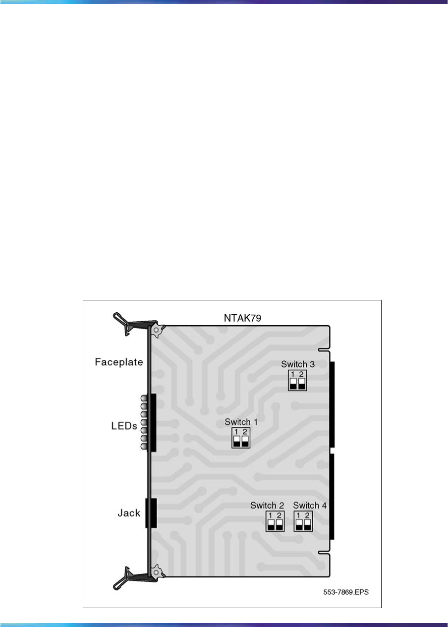
262 2.0 Mb PRI implementation
Each step is described in the pages that follow. The PRI hardware
installation procedure is the same regardless of the type of system at the
far-end that is, another system such as the AXE-10, or SYS-12.
Inspect the NTAK79 circuit card
•Locate the NTAK79 2.0 Mb circuit card and carefully remove it from its
packaging.
•Inspect the circuit card for any visible damage that occurred during
shipping.
Set the switches on the NTAK79
The NTAK79 incorporates four onboard dip switches. The tables that follow
provide information on the various settings and related functions of these
switches.
Note: The ON position for all the switches is positioned toward the
bottom of the card. This is indicated by a white dot printed on the board
adjacent to the bottom left corner of each individual switch.
Figure 83
NTAK79 with switch locations
Nortel Communication Server 1000
ISDN Primary Rate Interface Installation and Commissioning
NN43001-301 02.03 Standard
Release 5.5 7 December 2007
Copyright © 2003-2007, Nortel Networks
.
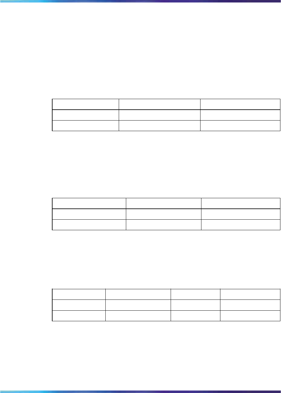
Install the NTAK79 PRI card 263
Set the switches on the circuit card according to the requirements of your
specific installation:
Switch SW1 - DCHI configuration
This switch enables and disables the onboard DCHI and sets the operating
mode of the DCHI.
For the U.K., use DPNSS1 mode. For all other countries, use Q.931 mode.
Table 92
Switch SW1
Switch Down (On) Up (Off)
SW 1-1 enable DCHI disable DCHI
SW 1-2 DPNSS1/DASS2 Q.931
Switch SW2 - Carrier impedance configuration
This switch sets the carrier impedance to either 1201/2or 751/2. Twisted pair
cable is usually associated with 1201/2. Coaxial cable is usually associated
with the 751/2setting.
Table 93
Switch SW2
Cable Type SW 2-1 SW 2-2
751/2Up (Off) Down (On)
1201/2Down (On) Up (Off)
Switch SW3 - Clock controller configuration
This switch enables and hardware disables the onboard Clock Controller.
SW 3-2 should be disabled if the onboard clock controller is not in use.
Table 94
Switch SW3
Switch Down (On) Up (Off) Note
SW 3-1 ——
Spare
SW 3-2 Disabled Enabled
Switch SW4 - Carrier shield grounding
This switch allows for the selective grounding of the Tx/Rx pairs of the
carrier cable. Closing the switch (down position) applies Frame Ground
(FGND) to the coaxial carrier cable shield, creating a 751/2unbalanced
configuration. This applies only to the NTBK05CA cable.
Nortel Communication Server 1000
ISDN Primary Rate Interface Installation and Commissioning
NN43001-301 02.03 Standard
Release 5.5 7 December 2007
Copyright © 2003-2007, Nortel Networks
.

264 2.0 Mb PRI implementation
Table 95
Switch SW4
Switch Down (On) Up (Off)
SW 4-1 Rx—FGND Rx—OPEN
SW 4-2 Tx—FGND Tx—OPEN
Note: The usual method is to ground the outer conductor of the receive
coax signal.
Insert the NTAK79
Slide the circuit card into card slot 1-9 in the Small System main cabinet, or
in slots 11-19, 21-29, 31-39, 41-49 of the first, second, third, and fourth IP
Expansion cabinets, respectively.
Secure the circuit card in the cabinet by locking the lock latch assemblies.
The card number associated with a 2.0 Mb PRI card is based on the slot in
which the card is installed.
Follow the instructions below to connect cables to the NTAK79 PRI card.
Also refer to Figure 84 "NTAK79 cabling" (page 265).
Procedure 40
Connecting the cables
Step Action
1In the cabling area, located directly below the card cage, remove
the retaining bar that secures the MDF cables. Connect the
NTBK05DA/CA interface cable to the 50-pin Amphenol connector
below the slot in which the NTAK79 is installed. reinstall the retaining
bar to secure the cable(s) in place.
2Terminate the NTBK05DA/CA carrier cable as required.
—End—
Nortel Communication Server 1000
ISDN Primary Rate Interface Installation and Commissioning
NN43001-301 02.03 Standard
Release 5.5 7 December 2007
Copyright © 2003-2007, Nortel Networks
.
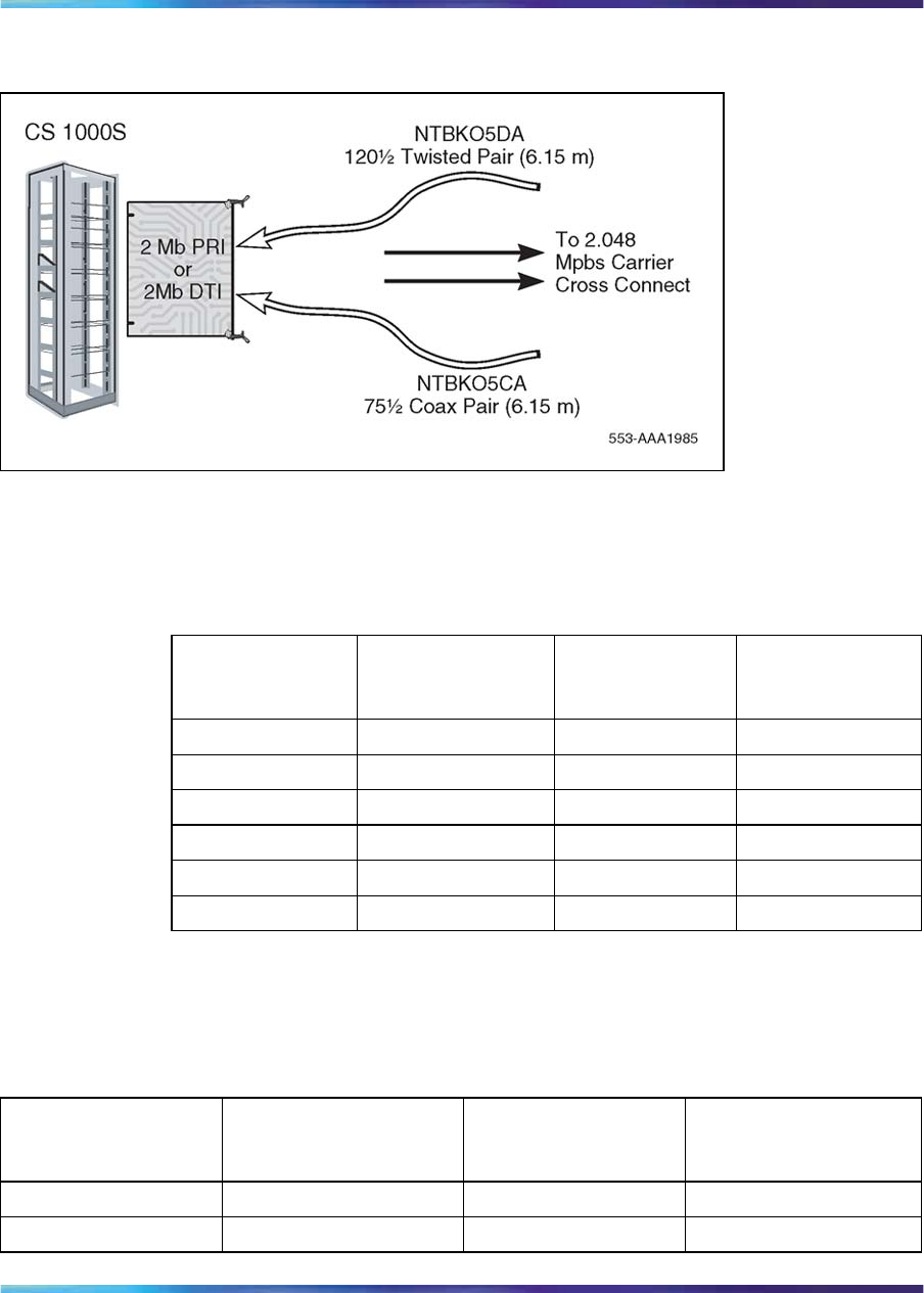
Install the NTAK79 PRI card 265
Figure 84
NTAK79 cabling
NTBK05DA pinouts
The pinouts for the NTBK05DA cable are as follows:
Table 96
NTBK05DA pinouts
From:
50-pin MDF
connector
To:
9-pin
connector color Signal
pin 23 pin 6 Black R0
pin 48 pin 7 White T0
pin 50 pin 9 Bare R0/T0 FGND
pin 24 pin 2 Black R1
pin 49 pin 3 Red T1
pin 25 pin 5 Bare R1/T1 FGND
NTBK05CA pinouts
The pinouts for the NTBK05CA cable are as follows:
Table 97
NTBK05CA pinouts
From:
50-pin MDF
connector
To:
Transmit coax
connector
To:
Receive coax
connector
To:
50-pin MDF
connector
pin 23 Inner conductor ——
pin 48 outer conductor ——
Nortel Communication Server 1000
ISDN Primary Rate Interface Installation and Commissioning
NN43001-301 02.03 Standard
Release 5.5 7 December 2007
Copyright © 2003-2007, Nortel Networks
.

266 2.0 Mb PRI implementation
From:
50-pin MDF
connector
To:
Transmit coax
connector
To:
Receive coax
connector
To:
50-pin MDF
connector
pin 24 —Inner conductor —
pin 49 —outer conductor —
pin 21 ——
pin 49
pin 46 ——
pin 48
Install the NTBK50 PRI card
The NTBK50 serves as a motherboard to the NTAK20 clock controller,
and either the NTBK51 Downloadable D-channel handler or the NTAK93
D-channel handler.
The steps required to install PRI are as follows:
Step Action
1Inspect the PRI card and daughterboards.
2Set the switches on the PRI card.
3Mount the daughterboard(s) on the PRI card.
4Insert the PRI card in the Small System main cabinet or Media
Gateway and any IP expansion cabinets.
5Connect the cables.
—End—
Each step is described in the pages that follow. The PRI hardware
installation procedure is the same regardless of the type of system at the
far-end.
Procedure 41
Inspecting the NTBK50 circuit card
Step Action
1Locate the NTBK50 2.0 Mb circuit card plus associated
daughterboard(s) and carefully remove them from their packaging.
2Inspect the circuit cards for any visible damage that occurred during
shipping.
—End—
Nortel Communication Server 1000
ISDN Primary Rate Interface Installation and Commissioning
NN43001-301 02.03 Standard
Release 5.5 7 December 2007
Copyright © 2003-2007, Nortel Networks
.
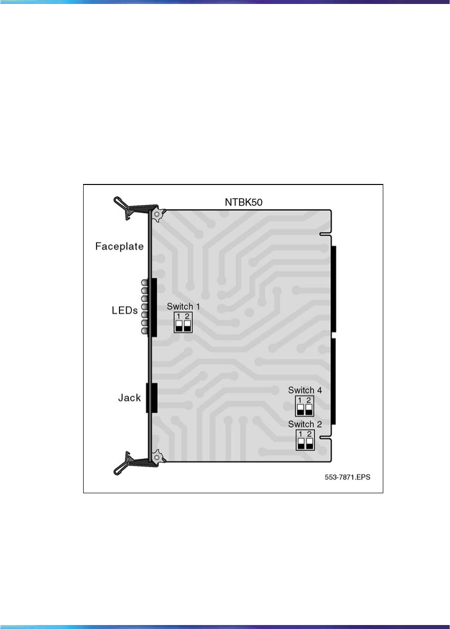
Install the NTBK50 PRI card 267
Set the switches on the NTBK50
The NTBK50 incorporates three onboard dip switches. The following tables
provide information on the various settings and related functions of these
switches.
Note: The ON position for all the switches is positioned toward the
bottom of the card. This is indicated by a white dot printed on the board
adjacent to the bottom left corner of each switch.
Figure 85
NTBK50 with switch locations
Set the switches on the circuit card according to the requirements of your
installation.
Switch SW1 - DCHI configuration (NTAK93 only)
This switch enables and disables the DCHI and sets the operating mode of
the DCHI. It is only used if an NTAK93 D-channel handler daughterboard is
being used. It has no effect when using the NTBK51 DDCH daughterboard.
Nortel Communication Server 1000
ISDN Primary Rate Interface Installation and Commissioning
NN43001-301 02.03 Standard
Release 5.5 7 December 2007
Copyright © 2003-2007, Nortel Networks
.
268 2.0 Mb PRI implementation
For the U.K., use DPNSS1 mode. For all other countries, use Q.931 mode.
Table 98
Switch SW1
Switch Down (On) Up (Off)
SW 1-1 ——
SW 1-2 DPNSS1/DASS2 Q.931
Switch SW2 - Carrier impedance configuration
This switch sets the carrier impedance to either 1201/2or 751/2. Twisted pair
cable is usually associated with 1201/2. Coaxial cable is usually associated
with the 751/2setting.
Table 99
Switch SW2
Cable type SW 2-1
753/4Down (On)
1203/4Up (Off)
Switch SW4 - Carrier shield grounding
This switch supports the selective grounding of Tx and Rx pairs of carrier
cable. Closing the switch (down position) applies Frame Ground (FGND) to
the coaxial carrier cable shield, creating a 751/2unbalanced configuration.
This applies only to the NTBK05CA cable.
Table 100
Switch SW3
Switch Down (On) Up (Off)
SW 4-1 Rx—FGND Rx—OPEN
SW 4-2 Tx—FGND Tx—OPEN
Note: The usual method is to ground the outer conductor of the receive
coax signal.
Mount the daughterboards on the NTBK50
Use the following procedure to mount and remove the NTAK20 CC and the
NTBK51 DDCH or NTAK93 DCHI daughterboards onto the NTBK50 PRI.
Install the NTAK93 or NTBK51 daughterboard before the NTAK20
daughterboard. Work on a flat surface when mounting or removing
daughterboards.
Nortel Communication Server 1000
ISDN Primary Rate Interface Installation and Commissioning
NN43001-301 02.03 Standard
Release 5.5 7 December 2007
Copyright © 2003-2007, Nortel Networks
.

Install the NTBK50 PRI card 269
Step Action
1Visually inspect the connector pins on the underside of the
daughterboard. Realign any bent pins prior to mounting.
2Place the NTBK50 down flat on an antistatic pad.
3From an overhead view, with the daughterboard parallel above
the NTBK50 and the connector pins aligned over the connector
sockets, align the mounting holes on the daughterboard with the
tops of the standoffs on the NTBK50 (see Figure 86 "Daughterboard
installation" (page 270)).
4Slowly lower the daughterboard toward the NTBK50, keeping the
standoffs in line with all four holes, until the holes rest atop the four
standoffs.
If more than slight pressure is required at this point, the connector
pins might not be aligned with the connector socket. If so, lift the
daughterboard off the NTBK50 and return to step 2.
5Gently apply pressure along the edge of the board where the
connector is located until the standoffs at the two corners adjacent
to the connector snap into a locked position. Then press down on
the two corners on the opposite side until they lock into place.
—End—
Nortel Communication Server 1000
ISDN Primary Rate Interface Installation and Commissioning
NN43001-301 02.03 Standard
Release 5.5 7 December 2007
Copyright © 2003-2007, Nortel Networks
.
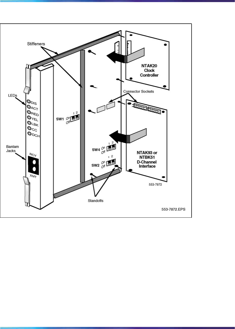
270 2.0 Mb PRI implementation
Figure 86
Daughterboard installation
Remove the daughterboards from the NTBK50
Use these guidelines to remove the NTAK20 and NTBK51 or NTAK93
from the NTBK50 PRI card. Because of the physical layout of the mother
and daughterboards, the NTAK20 should be removed before the NTAK93
or NTBK51.
1. Starting at the two corners opposite the connector, gently lift each
corner out of the locking groove of the standoff.
2. At the two corners adjacent to the connector, gently lift the entire side
until the mounting holes are clear of the locking groove of the standoff.
3. To remove the connector pins, grasp the edge of the board adjacent to
the connector and lift gently.
Nortel Communication Server 1000
ISDN Primary Rate Interface Installation and Commissioning
NN43001-301 02.03 Standard
Release 5.5 7 December 2007
Copyright © 2003-2007, Nortel Networks
.

Install the NTBK50 PRI card 271
If more than one NTBK50 card is installed, the additional cards may not
carry daughterboards, depending on system configuration. At least one
NTAK20 (per system) is always required.
Insert the NTBK50
Slide the circuit card into card slot 1-9 in the Small System main cabinet,
or in slots 11-19, 21-29, 31-39, 41-49 of the first, second, third, and fourth
IP expansion cabinets, respectively.
Secure the circuit card in the cabinet by locking the lock latch assemblies.
The card number associated with a 2.0 Mb PRI card is based on the slot in
which the card is installed.
Connect the cables
Follow the instructions below to connect cables to the NTBK50 PRI card.
Also refer to Figure 87 "NTBK50 cabling" (page 271).
•In the cabling area, located directly below the card cage, remove the
retaining bar that secures the MDF cables. Connect the NTBK05DA/CA
interface cable to the 50-pin Amphenol connector below the slot in
which the NTBK50 is installed. reinstall the retaining bar to secure the
cable(s) in place.
•Terminate the NTBK05DA/CA carrier cable as required.
Figure 87
NTBK50 cabling
NTBK05DA pinouts
The pinouts for the NTBK05DA cable are as follows:
Nortel Communication Server 1000
ISDN Primary Rate Interface Installation and Commissioning
NN43001-301 02.03 Standard
Release 5.5 7 December 2007
Copyright © 2003-2007, Nortel Networks
.
272 2.0 Mb PRI implementation
Table 101
NTBK05DA pinouts
From:
50-pin MDF
connector To:
9-pin connector color Signal
pin 23 pin 6 Black R0
pin 48 pin 7 White T0
pin 50 pin 9 Bare R0/T0 FGND
pin 24 pin 2 Black R1
pin 49 pin 3 Red T1
pin 25 pin 5 Bare R1/T1 FGND
NTBK05CA pinouts
The pinouts for the NTBK05CA cable are as follows:
Table 102
NTBK05CA pinouts
From:
50-pin MDF
connector
To:
Transmit coax
connector
To:
Receive coax
connector
To:
50-pin MDF
connector
pin 23 Inner conductor ——
pin 48 outer conductor ——
pin 24 —Inner conductor —
pin 49 —outer conductor —
pin 21 ——
pin 49
pin 46 ——
pin 48
PRI software implementation
The following information describes the process required to program basic
2.0 Mb PRI on the system.
PRI cards must be configured before defining the DCH links or PRI
applications.
Prompts which do not show a response are left as default. For more
information on any of these prompts, refer to Software Input Output
Administration (NN43001-611).
Task summary
Note: Before installing PRI cards in IP expansion cabinets or Media
Gateway systems, configure them for IP connectivity. Refer to LD 117
Nortel Communication Server 1000
ISDN Primary Rate Interface Installation and Commissioning
NN43001-301 02.03 Standard
Release 5.5 7 December 2007
Copyright © 2003-2007, Nortel Networks
.

PRI software implementation 273
in the Software Input Output Reference — Maintenance for further
information.
The following is a summary of the tasks in this section:
1. "LD 17 - Adding a PRI card" (page 273)
2. "LD 17 - Adding a DCHI or DDCH" (page 273)
3. "LD 15 - Defining a PRI customer" (page 275)
4. "LD 16 - Defining a PRI service route" (page 276)
5. "LD 14 - Defining service channels and PRI trunks" (page 277)
6. "LD 73 - Defining system timers and clock controller parameters" (page
277)
7. "LD 73 - Defining PRI parameters and thresholds" (page 278)
8. "LD 73 - Changing trunk pad category values" (page 280)
LD 17 - Adding a PRI card
Prompt Response Description
REQ CHG Change data.
TYPE CFN Configuration data block.
CEQU YES Changes to common equipment.
PRI2 xx The PRI2 digital card number, where: xx = 1-9 (Option 11C main
cabinet), 11-19 (IP expansion cabinet 1), 21-29 (IP expansion
cabinet 2), 31-39 (IP expansion cabinet 3), 41-49 (IP expansion
cabinet 4.)
xx = 11-14, 21-24, 31-34, 41-44 of the first, second, third and
fourth Media Gateway, respectively.
LD 17 - Adding a DCHI or DDCH
Prompt Response Description
REQ CHG Change data.
TYPE CFN Configuration data block.
Nortel Communication Server 1000
ISDN Primary Rate Interface Installation and Commissioning
NN43001-301 02.03 Standard
Release 5.5 7 December 2007
Copyright © 2003-2007, Nortel Networks
.

274 2.0 Mb PRI implementation
Prompt Response Description
ADAN NEW DCH xx
CHG DCH xx
OUT DCH xx
Add a primary D-channel (any unused SDI port.)
Change a primary D-channel.
Out the primary D-channel, where:
xx = 1-9 for Option 11C main cabinet, 11-19 for IP expansion
cabinet 1, 21-29 for IP expansion cabinet 2, 31-39 for IP
expansion cabinet 3, and 41-49 for IP expansion cabinet 4.
xx = 11-14, 21-24, 31-34, 41-44 of the first, second, third and
fourth Media Gateway, respectively.
CTYP MSDL
TMDI Card type where:
MSDL = The NTBK51BA Downloadable D-Channel
Daughterboard.
TMDI = TMDI (NTRB21) card.
CDNO 1-50 Card slot number used as the primary DDCH/DCHI.
Card slots 10, 20, 30, 40, and 50 are only applicable for
D-channel configuration of ISL or VNS.
PORT 1PORT set to "1".
USR PRI D-channel is for ISDN PRI only.
Note: 2.0 Mb only supports PRI or SHA user mode.
IFC xx Interface type.
DCHL xx PRI card number carries the D-channel. Must match entry made
for the "CDNO" associated with the "DCHI" prompt above.
Where: xx = 1-9 for Option 11C main cabinet, 11-19 for IP
expansion cabinet 1, 21-29 for IP expansion cabinet 2, 31-39 for
IP expansion cabinet 3, and 41-49 for IP expansion cabinet 4.
xx = 11-14, 21-24, 31-34, 41-44 of the first, second, third and
fourth Media Gateway, respectively.
PRI2 <CR> Additional PRI Loops controlled by this DCHI. Remember
one DCHI can control up to 16 PRI loops going to the same
destination. For the system, the maximum limit is eight loops.
OTBF 1-(16)-127 Number of output request buffers. Note: for a single PRI link,
leave this prompt at default (16). Add 5 output request buffers
per additional link.
SIDE NET (USR) Prompted only if IFC is set to SL1. NET = network, the
controlling switch USR = slave to the controller
Nortel Communication Server 1000
ISDN Primary Rate Interface Installation and Commissioning
NN43001-301 02.03 Standard
Release 5.5 7 December 2007
Copyright © 2003-2007, Nortel Networks
.

PRI software implementation 275
Prompt Response Description
RLS XX Software release of far-end. This is the current software release
of the far-end. If the far-end has an incompatible release of
software, it prevents the sending of application messages, for
example, ’Network Ring Again.
RCAP MSL MSDL RCAP capability.
OVLR <CR> Allow or disallow overlap receiving on a D-channel. Default is
NO.
LAPD YES (NO) Change LAPD parameters. Enter carriage return if timers are
left at default. The following timers are prompted only if LAPD is
set to YES. They are all left at default during initial setup.
- T23 1-(20)-31 Interface guard timer checks how long the interface takes to
respond. In units of 0.5 seconds (default 20 = 10 seconds).
T200 2-(3)-40 Retransmission timer in units of 0.5 seconds (default 3 = 1.5
seconds).
- N200 1-(3)-8 Maximum number of retransmissions.
- N201 4(260) Maximum number of octets in information field.
- K 1-(7)-32 Maximum number of outstanding unacknowledged frames
(NAKS).
LD 15 - Defining a PRI customer
Prompt Response Description
REQ: NEW
CHG Add new data.
Change existing data.
TYPE: NET Networking data.
CUST 0-99 Customer number
Range for Large System, Call Server 1000E, and
Media Gateway 1000E
0-31 Range for Small System, Media Gateway 1000B
LDN XXXX Enter the customer’s Listed Directory Number.
AC2 Access Code 2. Enter call types (type of number) that use
access code 2. Multiple responses are permitted. This prompt
only appears on NARS equipped systems. If a call type is not
entered here, it automatically defaults to access code 1.
NPA E.164 National.
NXX E.164 Subscriber.
INTL International.
SPN Special Number.
LOC Location Code.
ISDN YES Customer is equipped with ISDN.
Nortel Communication Server 1000
ISDN Primary Rate Interface Installation and Commissioning
NN43001-301 02.03 Standard
Release 5.5 7 December 2007
Copyright © 2003-2007, Nortel Networks
.

276 2.0 Mb PRI implementation
Prompt Response Description
PNI 1-32700 Customer private network identifier. This number is unique to
this customer in the private network. For example, it is used as
part of the setup message for feature operation such as Network
Ring Again and Network ACD. Note that if PNI is set to zero (0),
NRAG and NACD does not work.
HNPA NPA Telephone area code for this system. Sent in the setup message
as calling line identification.
HNXX NXX Telephone local exchange code for this system. Sent in the
setup message as calling line identification.
HLOC XXX Home location code (NARS)
LSC 1-9999 One to four digit Local Steering Code established in the
Coordinated Dialing Plan (CDP). The LSC prompt is required for
Calling Line ID and Network ACD.
LD 16 - Defining a PRI service route
Prompt Response Description
REQ NEW CHG Add new data.
Change existing data.
TYPE RDB Route data block.
TKTP xxx Trunk type.
DTRK YES Digital trunk route.
DGPT PRI2 2.0 Mb PRI. Prompted only if PRA = YES in LD15.
ISDN YES ISDN option.
MODE PRI Route used for PRI only.
PNI 1-32700 Customer private network identifier. Is the same as the CDB
PNI at far-end.
IFC xx Interface type.
CHTY BCH Signaling type. Prompted if DTRK is YES. D-channel signaling
for B-channels.
CTYP aaa
<CR> Call Type. Enter the call type to associate with the outgoing
route for direct dialing using the trunk access code (instead of
NARS access code).
INAC YES Insert Access Code. Permits the NARS AC1 or AC2 access
code to be reinserted automatically on an incoming ESN call.
This prompt only appears on a TIE route and is set to "YES" for
features such as Network ACD to function.
Nortel Communication Server 1000
ISDN Primary Rate Interface Installation and Commissioning
NN43001-301 02.03 Standard
Release 5.5 7 December 2007
Copyright © 2003-2007, Nortel Networks
.

PRI software implementation 277
Prompt Response Description
On an existing ESN network, setting this prompt to "YES"
may also require modifying the Digit Manipulation Index (DMI)
associated with this route at the far-end (so the Access Code is
not reinserted twice). The INSERT prompt (INST) is bypassed if
INAC = YES.
LD 14 - Defining service channels and PRI trunks
Prompt Response Description
REQ NEW
CHG Add new data.
Change existing data.
Note: When assigning several members at once use the multiple
create command NEW XX.
TYPE TIE TIE trunk only, allowed between MSL-1.
TN l ch Loop and channel for digital trunks
RTMB 0-511 1-4000 Route number and Member number
Range for Large System and CS 1000E system.
0-127 1-4000 Range for Meridian 1 Small System, Media Gateway 1000B,
...
LD 73 - Defining system timers and clock controller parameters
Prompt Response Description
REQ CHG Change data.
TYPE PRI2 2.0 Mb PRI.
FEAT SYTI System timers.
CCO xx Card slot number for Clock Controller 0.
PREF CCO xx Card number of PRI/DTI/SILC containing the primary clock
reference for the main cabinet
SREF CCO xx Card number of PRI/DTI/SILC containing the primary clock
reference for the main cabinet
CC1 xx Card number for Clock Controller 1.
PREF CC1 xx Primary Reference DTI/PRI loop for Clock controller one.
SREF CC1 xx Primary Reference DTI/PRI loop for Clock controller one.
CC2 xx Card number for Clock Controller 2.
PREF CC2 xx Card number of PRI/DTI/SILC or DTI2/PRI2/SILC containing the
primary clock reference.
SREF CC2 xx Card number of PRI/DTI/SILC or DTI2/PRI2/SILC containing the
primary clock reference.
CC3 xx Card number for Clock Controller 3.
Nortel Communication Server 1000
ISDN Primary Rate Interface Installation and Commissioning
NN43001-301 02.03 Standard
Release 5.5 7 December 2007
Copyright © 2003-2007, Nortel Networks
.

278 2.0 Mb PRI implementation
Prompt Response Description
PREF CC3 xx Card number of PRI/DTI/SILC or DTI2/PRI2/SILC containing the
primary clock reference.
SREF CC3 xx Card number of PRI/DTI/SILC or DTI2/PRI2/SILC containing the
primary clock reference.
CC4 xx Card number for Clock Controller 4.
PREF CC4 xx Card number of PRI/DTI/SILC or DTI2/PRI2/SILC containing the
primary clock reference.
SREF CC4 xx Card number of PRI/DTI/SILC or DTI2/PRI2/SILC containing the
primary clock reference.
CCAR 0-(15) Clock Controller Audit Rate. Enter the time (in minutes) between
normal CC audits.
LD 73 - Defining PRI parameters and thresholds
Prompt Response Description
REQ CHG Change data.
TYPE PRI2 2.0 Mb PRI.
FEAT LPTI Loop timers.
LOOP X X is the slot number of the 2.0 Mb PRI card.
MFF AFF (CRC) Alternate mode or CRC multiframe mode.
ALRM (REG) ALT Default or alternate alarms selected.
G10S
SLP mc mt oc ot Slip error count.
where
mc = Maintenance threshold slip count, 1- (5)-255.
mt = Maintenance threshold time, default 24 hours.
oc = Out-of-service threshold slip count, 1-(30)-255.
ot = Out-of-service threshold time, default 1 hour.
BPV n1 n2 Bipolar violation error count. Range is 1-(128)-255 for n1,
1-(122)-255 for n2.
where
n1 is multiplied by 16 to obtain the actual count, giving an
actual count range of 16-4080.
Nortel Communication Server 1000
ISDN Primary Rate Interface Installation and Commissioning
NN43001-301 02.03 Standard
Release 5.5 7 December 2007
Copyright © 2003-2007, Nortel Networks
.

PRI software implementation 279
Prompt Response Description
CRC n1 n2 Cyclic redundancy check error count. Range is 1-(201)-255 for
n1, 1-(97)-255 for n2.
where
n1 is multiplied by 4 to obtain the actual count, giving an
actual count range of 4-1020.
FAP n1 n2 Frame alignment problem error count. Range is 1-(28)-255 for
n1, (1)-255 for n2.
RATS 1-(10)-15 Number of seconds firmware has to check BPV/CRC/FAP for
excessive error rate.
GP2 T2 mt dt ct ot Group 2 error thresholds.
This is the maximum amount of time that can elapse before
software checks the associated thresholds of 120 to 32,640
msec and rounds it to the closest multiple of 128 msec.
where
T2 = Error count values are in the range 1-(20)-255.
mt = Maintenance threshold time (MNT)(default =100S).
dt = No new data calls threshold time (NNDC)(default =12S).
ct = No new calls threshold time (NNC)(default =12S).
ot = Out of service threshold time (OOS)(default =4S).
Note 1: The following requirements must be met for input mt
= >dt = >ct = >ot.
Note 2: Threshold times are one of the following: nnnnT, nnnS,
nnnM, or nnH, where nnnn is and integer and T,S,M, or H show
the increments of use. The values are as follows:
-nnnnT is the time in 20 millisecond increments (nnnn = 20-5000)
- nnnS is the time in 1 second increments (nnn= 1-240)
- nnnM is the time in 1 minute increments (nnn= 1-240)
-nnH is the time in 1 hour increments (nn= 1-24)
MNG1 nnnM Maintenance Guard time Group 1, default = 15M.
NCG1 nnnM No New Calls Guard time Group 1, default = 15M.
OSG1 nnnM Out Of Service Guard time Group 1, default = 15M.
MNG2 nnnS Maintenance Guard time Group 2, default = 15S.
NCG2 nnnS No New Calls Guard time Group 2, default = 15S.
OSG2 nnnS Out Of Service Guard time Group 2, default = 15S.
Nortel Communication Server 1000
ISDN Primary Rate Interface Installation and Commissioning
NN43001-301 02.03 Standard
Release 5.5 7 December 2007
Copyright © 2003-2007, Nortel Networks
.

280 2.0 Mb PRI implementation
Prompt Response Description
PERS ttt Persistence Timer for Group II problems.
Enter 0-256 msec in increments of 2 msec. Default is 50
(=100ms).
CLRS ttt Clearance Timer for Group II problems. Enter 0 - 256 msec in
increments of 2 msec. Default is 50 (=100ms).
OOSC nnn Out-of-Service Counter.
Range for nnn of 0-255 with a default of 5.
LD 73 - Changing trunk pad category values
Prompt Response Description
REQ CHG Change data.
TYPE PRI2 2.0 Mb PRI.
FEAT PADS
PDCA #PAD table-0 is default and is hard coded.
The following prompts define the pad levels.
The receiving pad code is rand the transmission pad code is t. These entries have the range 0-15.
The pad values (in decibels) relating to these codes are shown after this table.
ONP rt On-premises extension.
DSET rt Meridian Digital set.
Prompted only if the 2.0 Mb Gateway feature is equipped.
OPX rt Off-premises extension.
DTT rt Digital TIE trunks.
SDTT rt Digital Satellite TIE trunks.
NTC rt Nontransmission compensated.
TRC rt Transmission compensated.
DCO rt Digital COT, FEX, WAT, and DID trunks.
VNL rt Via Net Loss.
DTO rt 2.0 Mb PRI2 digital TOLL office trunks.
ACO rt Analog CO or WATS trunks.
AFX rt Analog FEX trunks.
ADD rt Analog DID trunks.
SATT rt Analog satellite TIE trunks.
ATO rt Analog TOLL office trunks.
PRI2 rt 2.0 Mb PRI trunk.
Prompted only if the 1.5/2.0 Mb Gateway feature is equipped
and TYPE=2.0 Mb PRI.
Nortel Communication Server 1000
ISDN Primary Rate Interface Installation and Commissioning
NN43001-301 02.03 Standard
Release 5.5 7 December 2007
Copyright © 2003-2007, Nortel Networks
.
PRI software implementation 281
Prompt Response Description
XUT rt Analog CO trunk.
Prompted only if the 1.5/2.0 Mb Gateway feature is equipped
and TYPE=PRI2.
XEM rt Analog TIE trunk.
Prompted only if the 1.5/2.0 Mb Gateway feature is equipped
and TYPE=PRI2.
Table 103 "Pad values" (page 281) shows the pads available to 2.0 Mb PRI.
Positive dB represents loss and negative dB represents gain.
Table 103
Pad values
code 01234567
value
(dB) 0.0 +1.0 +2.0 +3.0 +4.0 +5.0 +6.0 +7.0
code 8 9 101112131415
value
(dB) +8.0 +9.0 +10.0 +11.0 +12.0 +13.0 +14.0 -1
code 16 17 18 19 20 21 22 23
value
(dB) -2 -3 -4 -5 -6 -7 -8 -9
code 24 25 26
value
(dB) -10 idle +0.6
Configure DPNSS1 with IP expansion cabinets/Media Gateway systems
For Small Systems, when configuring a PRI2 card slot number for DPNSS1,
the response to the DDCS prompt in LD 17 is: 1-9 (Option 11C Cabinet),
11-19 (IP expansion cabinet 1), 21-29 (IP expansion cabinet 2), 31-39 (IP
expansion cabinet 3), 41-49 (IP expansion cabinet 4).
Configure ISDN BRI trunking with IP expansion cabinets/Media Gateway
systems
For Small Systems, when configuring the MISP card slot number for ISDN
BRI trunking in LD 27, the response to the LOOP prompt is: 1-9 (Option
11C Cabinet), 11-19 (IP expansion cabinet 1), 21-29 (IP expansion cabinet
2), 31-39 (IP expansion cabinet 3), 41-49 (IP expansion cabinet 4).
For Small Systems, when configuring the DSL for ISDN BRI trunking in
LD 27, the response to the MISP prompt is: 1-9 (Option 11C Cabinet),
11-19 (IP expansion cabinet 1), 21-29 (IP expansion cabinet 2), 31-39 (IP
expansion cabinet 3), 41-49 (IP expansion cabinet 4).
Nortel Communication Server 1000
ISDN Primary Rate Interface Installation and Commissioning
NN43001-301 02.03 Standard
Release 5.5 7 December 2007
Copyright © 2003-2007, Nortel Networks
.

282 2.0 Mb PRI implementation
Nortel Communication Server 1000
ISDN Primary Rate Interface Installation and Commissioning
NN43001-301 02.03 Standard
Release 5.5 7 December 2007
Copyright © 2003-2007, Nortel Networks
.

283
2.0 Mb ISL implementation
Contents This section contains information on the following topics:
"Overview" (page 283)
"ISL hardware requirements" (page 283)
"ISL hardware installation" (page 286)
"ISL software implementation" (page 288)
Overview This chapter provides the information required to implement ISL on the
system including:
•hardware and software installation
•implementation of components needed to provide basic call service
ISDN features are treated separately in the chapter devoted to ISDN feature
implementation.
This chapter assumes that ESN implementation is already in place. It also
assumes that the reader has a basic understanding of NARS and CDP.
Two modes of ISL are available: shared and dedicated. This chapter covers
ISL installation in dedicated mode using dedicated and leased lines. Shared
mode installations are done according to the instructions supplied for PRI,
with the noted exceptions.
ISL hardware requirements
ISL, regardless of the operation mode, uses analog or digital TIE lines as
B-channels.
Nortel Communication Server 1000
ISDN Primary Rate Interface Installation and Commissioning
NN43001-301 02.03 Standard
Release 5.5 7 December 2007
Copyright © 2003-2007, Nortel Networks
.

284 2.0 Mb ISL implementation
ISL in shared mode
In shared mode, PRI hardware is required in addition to the existing TIE
lines interface cards.
•NT8D15 Analog trunk card(s)
•NTAK02 SDI/DCH, NTAK10 2.0 Mb DTI, NTAK79 2.0 Mb PRI, or
NTBK50 2.0 Mb PRI card(s)
Figure 88
ISL in shared mode
ISL in dedicated mode using leased line
The following hardware is required:
•NTAK02 SDI/DCH D-channel handler interface
•A modem capable of the following: (such as Ventel 2400-33 or 2400
Plus II)
— minimum of 2400 baud
— synchronous operation
— must support leased line (also known as private line or point-to-point)
operation
•NTAK19BA 4-Port SDI Cable
Nortel Communication Server 1000
ISDN Primary Rate Interface Installation and Commissioning
NN43001-301 02.03 Standard
Release 5.5 7 December 2007
Copyright © 2003-2007, Nortel Networks
.

ISL hardware requirements 285
Figure 89
ISL in dedicated mode using leased line
ISL in dedicated mode using dialup modem
The requirements are as follows:
•NTAK02 SDI/DCH D-channel handler interface.
•Modems such as the Ventel 2400, Hayes 2400 (the Hayes Smartmodem
2400 cannot be used on leased lines) or Gandalf 2400 that can support
2 or 4-wire leased line operation. 4-wire operation must be specified
when ordering. Otherwise, modems are factory shipped for 2-wire
operation. Modems capable of the following:
— autodial capability
— minimum of 2400 baud
— synchronous operation
— programmable so that one modem originates the call while the other
auto-answers
•NTAK19BA 4-port SDI cable.
•NT8D09 500 set line card.
Nortel Communication Server 1000
ISDN Primary Rate Interface Installation and Commissioning
NN43001-301 02.03 Standard
Release 5.5 7 December 2007
Copyright © 2003-2007, Nortel Networks
.
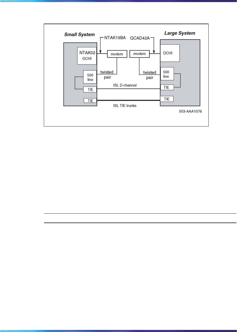
286 2.0 Mb ISL implementation
Figure 90
ISL in dedicated mode using dialup modem
ISL hardware installation
Shared mode
The hardware installation is identical to the PRI installation, with the addition
of analogue or digital TIE trunks (or both).
Dedicated mode
The NTAK02 connects to the modem through the NTAK19BA 4-port cable.
Only ports 1 and 3 are available for use as DCHIs.
Procedure 42
Installing the NTAK02
Step Action
1Set option switches/jumpers on the DCHI card, as shown in Table
104 "NTAK02 switch settings" (page 287) and Table 105 "NTAK02
jumper settings" (page 287), for mode of operation that is, RS232 or
RS422 and DTE or DCE.
2Install the NTAK02 in any spare slot 1-9 of the Main Cabinet or slots
11-14 of the Media Gateway.
3Install the NTAK19BA four port cable on the 50-pin Amphenol
connector associated with the slot holding the NTAK02.
Nortel Communication Server 1000
ISDN Primary Rate Interface Installation and Commissioning
NN43001-301 02.03 Standard
Release 5.5 7 December 2007
Copyright © 2003-2007, Nortel Networks
.
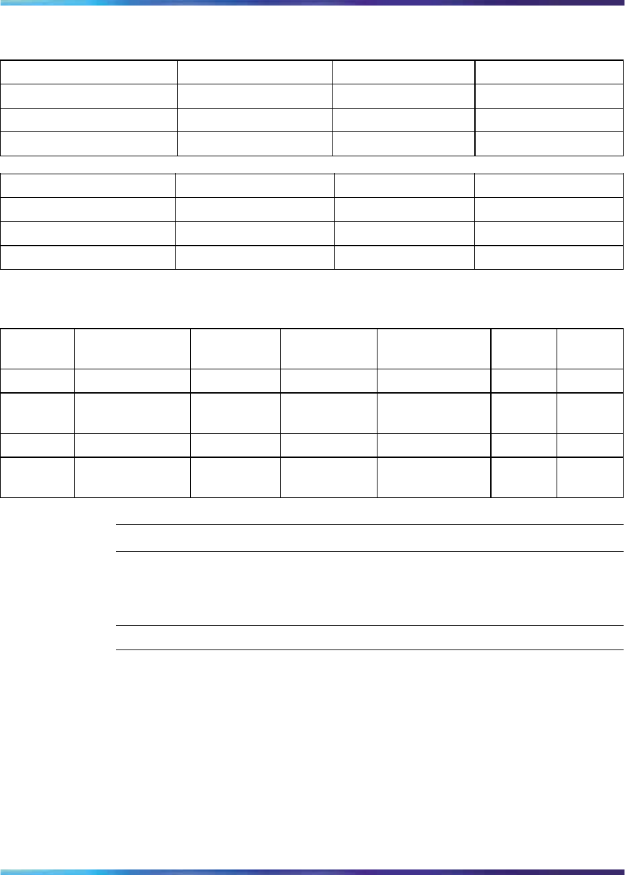
ISL hardware installation 287
Table 104
NTAK02 switch settings
Port 0 Port 1 SW1-1 SW1-2
SDI DCH OFF OFF
SDI DPNSS1 OFF ON
—ESDI ON ON
Port 2 Port 3 SW1-3 SW1-4
SDI DCH OFF OFF
SDI DPNSS1 OFF ON
—ESDI ON ON
Table 105
NTAK02 jumper settings
Unit Jumper
location Strap for
DTE Strap for
DCE Jumper
location RS422 RS232
Unit 0 J10 C - B B - A
Unit 1 J7
J6 C-B
C-B B-A
B-A J9
J8 C-B
C-B B-A
B-A
Unit 2 J5 C - B B - A
Unit 3 J4
J3 C-B
C-B B-A
B-A J2
J1 C-B
C-B B-A
B-A
—End—
Procedure 43
Setting up the D-channel
Step Action
1If this is a dedicated mode installation using leased line modems,
the D-channel connects the DCHI with the far-end modem over a
dedicated leased line. Synchronous modems with a minimum 2400
baud data rate must be configured. Modems must support leased
line capability and synchronous mode. The Hayes Smartmodem
2400 cannot be used on leased lines.
Nortel Communication Server 1000
ISDN Primary Rate Interface Installation and Commissioning
NN43001-301 02.03 Standard
Release 5.5 7 December 2007
Copyright © 2003-2007, Nortel Networks
.

288 2.0 Mb ISL implementation
If this a dedicated mode using dialup modems, modems such as
Hayes 2400, Ventel 2400 or Gandalf 2400 can be used. In this
configuration, the DCHI connects to a modem which is connected
to a 500 set line card. The call connects to the far-end through the
500 set-to-TIE trunk path.
Program the modem at one end in the autodial mode, so it
automatically initiates a call to the other end at power up. The
autodial number must be coordinated with the far-end switch. The
originating modem has this autodial number stored internally as part
of the modem configuration routine.
The far-end modem need only be setup for auto-answer.
—End—
ISL software implementation
There are two modes of ISDN Signaling Link (ISL) operation, shared mode
and dedicated mode.
Shared mode
The NTAK79 onboard DCHI supports ISDN PRI signaling and ISL trunks.
The configuration is basically the same as the PRI D-channel, with the
D-channel also supporting ISL trunks.
The DTI/PRI software implementation sequence can be used (refer to the
appropriate chapters for more information) with the following exceptions.
LD 17 - Shared mode
Prompt Response Description
USR SHA D-channel for ISL in "shared" mode, used for both ISDN PRI and ISL.
ISLM 1-240 Number of ISL B-channel (trunks) controlled by the D-channel (no
default value).
LD 16 - Interface type
Prompt Response Description
IFC SL1 Interface type must be SL1 (this is the only type supported for ISL).
MODE ISLD TIE route used for ISL members.
LD 14 - Channel identifier
Prompt Response Description
CHID 1-240 Channel identifier for ISL channels. Must be coordinated with the
far-end.
Nortel Communication Server 1000
ISDN Primary Rate Interface Installation and Commissioning
NN43001-301 02.03 Standard
Release 5.5 7 December 2007
Copyright © 2003-2007, Nortel Networks
.

ISL software implementation 289
Dedicated mode
The DCHI uses the NTAK02 circuit card and does not support ISDN PRI
signaling. The DCHI is reserved for ISL use only. The D-channel can
communicate with the far-end by means of a dedicated leased line modem
or dialup modem.
Note that the following implementation relates to analogue TIE trunks being
used as B-channels. In the case where DTI/PRI trunks are also used, then
LD 17 digital loop (2.0 Mb PRI) and LD73 (2.0 Mb PRI/SYTI) must also be
configured with the appropriate clocking and threshold settings.
For ISL dedicated mode using a dialup modem, a 500 set, TIE trunk
route and member must be programmed (used for D-channel). Table 106
"Configuring basic ISL capability" (page 289) summarizes the required
steps.
Table 106
Configuring basic ISL capability
Step LD Action
117
Configure the D-channel for ISL use.
215
Enable ISDN option.
316
Enable the ISL option on a per route basis, assign a D-channel
for each route.
414
Assign a channel identification to each trunk with the ISL
option.
LD 17 - Configure the D-channel for ISL
Prompt Response Description
REQ CHG Change existing data
TYPE CFN Configuration data block.
ADAN NEW DCH 0-79 Add primary D-channel.
CTYP DCHI D-channel card type.
CDNO 0-15
1-9 11-19 21-29,
31-39 41-49
1-50
Serial Data Interface (SDI) Card number.
Number the SDI cards logically with the
system.
MSDL application small system Card
number
DCHI small system Card number
PORT 1Must be set to 1.
Nortel Communication Server 1000
ISDN Primary Rate Interface Installation and Commissioning
NN43001-301 02.03 Standard
Release 5.5 7 December 2007
Copyright © 2003-2007, Nortel Networks
.

290 2.0 Mb ISL implementation
Prompt Response Description
USR PRI D-channel for ISDN PRI only.
IFC SL1 Interface type.
DCHL 1-9 PRI2 card number. (Must match entry for
CDNO).
SIDE NET (USR) Net: network, the controlling switch.
User: slave to controller.
RLS XX Software release of far-end. This is the
current software release of the far-end. If
the far-end has an incompatible release
of software, it prevents the sending of
application messages. For example, for
Network Ring Again.
CLOK D-channel clock type for signaling.
EXT Source of D-channel clock is external to
DCHI card (in this case the DTI/PRI circuit
card). Normally, EXT is used for PRI/ISL.
Note 1: Do not confuse this clock with
the E1 span Clock Controller found on the
NTAK10/79. This clock is in reference to the
DCHI synchronous mode of operation.
Note 2: If directly connecting two DCHI ports
with out the use of modems, set "CLOK" to
"EXT" on one side and "INT" on the other.
LAPD YES,(NO) Change LAPD parameters. Simply carriage
return if timers are to be left at default value.
The following timers are prompted only if
LAPD is set to YES. The following can all be
left at default during initial setup.
T23 1-(20)-31 Interface guard timer checks how long the
interface takes to respond. In units of 0.5
seconds (default 20 = 10 seconds).
T200 2-(3)-40 Retransmission timer in units of 0.5 seconds
(default 3 = 1.5 seconds).
N200 1-(3)-8 Maximum number of retransmissions.
Nortel Communication Server 1000
ISDN Primary Rate Interface Installation and Commissioning
NN43001-301 02.03 Standard
Release 5.5 7 December 2007
Copyright © 2003-2007, Nortel Networks
.

ISL software implementation 291
Prompt Response Description
N201 4(260) Maximum number of octets in information
field.
K 1-(7)-32 Maximum number of outstanding
unacknowledged frames (NAKS).
LD 15 - Enable the ISDN option
Prompt Response Description
REQ: NEW
CHG Add new data.
Change existing data.
TYPE: NET Networking data.
CUST 0-99 Customer number
Range for Large System, Call Server 1000E, and Media
Gateway
1000E
0-31 Range for Small System, Media Gateway 1000B,
ISDN YES Customer is equipped with ISDN.
PNI 1-32700 Customer private network identifier. MUST be unique to
this customer in the private network. Used as part of the
setup message for feature operation such as Network Ring
Again and Network ACD.
HNPA NPA Telephone area code for this system. Sent as part of setup
message as CLID.
HNXX NXX Telephone local exchange code for this system. Sent as
part of setup message for calling line identification.
HLOC XXX Home location code (NARS).
LSC 1-9999 One to four digit Local Steering Code established in the
Coordinated Dialing Plan (CDP). The LSC prompt is
required for Calling Line ID and Network ACD.
AC2 Access Code 2. Enter call types (type of number) that use
access code 2. Multiple responses are permitted. This
prompt only appears on NARS equipped systems. If a call
type is not entered here, it is automatically defaulted to
access code 1.
NPA E.164 National.
NXX E.164 Subscriber.
INTL International.
SPN Special Number.
LOC Location Code.
Nortel Communication Server 1000
ISDN Primary Rate Interface Installation and Commissioning
NN43001-301 02.03 Standard
Release 5.5 7 December 2007
Copyright © 2003-2007, Nortel Networks
.

292 2.0 Mb ISL implementation
LD 16 - Enable the ISL option
Prompt Response Description
REQ NEW CHG Add new data.
Change existing data.
TYPE RDB Route data block.
CUST xx Customer number, as defined in LD 15
ROUT 0-511 Route number
Range for Large System and CS 1000E system.
0-127 Range for Meridian 1 Small System, Media Gateway
1000B.
TKTP TIE TIE trunk route.
DTRK YES
NO Enter YES if this is a Digital Trunk Interface (DTI or PRI).
ISDN YES ISDN option.
MODE ISLD Route for ISL application.
DCHI XX DCHI port number in CFN to carry the D-channel for this
TIE trunk route.
PNI 1-32700 Customer private network identifier. Must be the same as
the CDB PNI at the fa- end.
IFC Interface type.
SLl System to system.
CTYP aaa
<CR> Call Type. Enter the call type to be associated with the
outgoing route for direct dialing using the trunk access
code (instead of NARS access code).
INAC YES Insert Access Code. Permits the NARS AC1 or AC2
access code to be reinserted automatically on an incoming
ESN call.
LD 14 - Assign a channel identifier
Prompt Response Description
REQ NEW
CHG Add new data.
Change existing data.
TYPE TIE TIE trunk type.
TN lscu Terminal Number
Format for Large System and CS 1000E system,
where l = loop, s = shelf, c = card, u = unit.
cu Format for Meridian 1 Small System, Media Gateway 1000B
where c = card and u = unit.
RTMB 0-511 1-4000 Route number and Member number
Range for Large System and CS 1000E system.
Nortel Communication Server 1000
ISDN Primary Rate Interface Installation and Commissioning
NN43001-301 02.03 Standard
Release 5.5 7 December 2007
Copyright © 2003-2007, Nortel Networks
.

ISL software implementation 293
Prompt Response Description
0-127 1-4000 Range for Meridian 1 Small System, Media Gateway 1000B.
CHID 1-240 Channel identifier for ISL channels (remove with Xnn). Must be
coordinated with far-end (no default value).
Nortel Communication Server 1000
ISDN Primary Rate Interface Installation and Commissioning
NN43001-301 02.03 Standard
Release 5.5 7 December 2007
Copyright © 2003-2007, Nortel Networks
.

294 2.0 Mb ISL implementation
Nortel Communication Server 1000
ISDN Primary Rate Interface Installation and Commissioning
NN43001-301 02.03 Standard
Release 5.5 7 December 2007
Copyright © 2003-2007, Nortel Networks
.

295
Nonstandard cables
Contents The section contains information on the following topics:
"Introduction" (page 296)
"NT5K40AA, NT5K41AA, NT5K86AA" (page 296)
"NT8D7206, NT8D7207" (page 296)
"QCAD128" (page 297)
"QCAD129" (page 298)
"QCAD133" (page 298)
"NT8D7205" (page 299)
"QCAD328" (page 300)
"NT8D74 Clock Controller to InterGroup cable" (page 301)
"NT8D75 Clock Controller to Clock Controller cable" (page 301)
"NT8D79 PRI/DTI to Clock Controller cable" (page 301)
"NT8D83 PRI/DTI to I/O cable" (page 301)
"NT8D85 Network to IPE cable" (page 302)
"NT8D86 Network to I/O cable" (page 302)
"NT8D97AX PRI/DTI I/O to MDF cable" (page 302)
"NT9J93AD PRI/DTI Echo Canceller to I/O cable" (page 303)
"NTND26 PRI to MSDL cables" (page 303)
Nortel Communication Server 1000
ISDN Primary Rate Interface Installation and Commissioning
NN43001-301 02.03 Standard
Release 5.5 7 December 2007
Copyright © 2003-2007, Nortel Networks
.
296 Nonstandard cables
"NTND27 MSDL to I/O panel cables" (page 303)
"NTND98 PRI to I/O panel cables" (page 303)
Introduction This section provides information required to build systems cables of
nonstandard lengths for ISDN PRI applications.
NT5K40AA, NT5K41AA, NT5K86AA
These cables are used to transport the 2Mb digital signal from the faceplate
connector on the PRI card to the Line Terminating Equipment interface.
•Standard lengths:
— NT5K40AA - 4 m (13 ft.)
— NT5K41AA - 8 m (26 ft.)
— NT5K86AA - 12m (39 ft.)
•Construction - 75 ohm dual co-axial type with solid inner conductor and
braided shield.
•J1 Connector - 15-pin, male, subminiature D with jackscrews
•J2 Connector - 75 ohm BNC crimp plug
•J3 Connector - 75 ohm BNC crimp plug
Table 107
NT5K40AA, NT5K41AA, NT5K86AA wire list
From
(pack end) To
(I/O end) Signal
J1-1 J2 Inner Conductor XTIP (transmit)
J1-9 J2 Shield XRING (transmit)
J1-3 J3 Inner Conductor RTIP (receive)
J1-11 J3 Shield RRING (receive)
J1-9 J3 Shield FRAME GROUND
NT8D7206, NT8D7207
This cable is used to transport the 2Mb/s digital signal from the PRI pack to
the I/O assembly located at the cabinet bulkhead.
•Standard length -
3.05 m (10 ft.) for Half Group systems and Single group systems
•Construction - 24 AWG, stranded foil-shielded twisted pairs
•P1 Connector (Pack end) - 9-pin, male, subminiature D, with jackscrews
Nortel Communication Server 1000
ISDN Primary Rate Interface Installation and Commissioning
NN43001-301 02.03 Standard
Release 5.5 7 December 2007
Copyright © 2003-2007, Nortel Networks
.
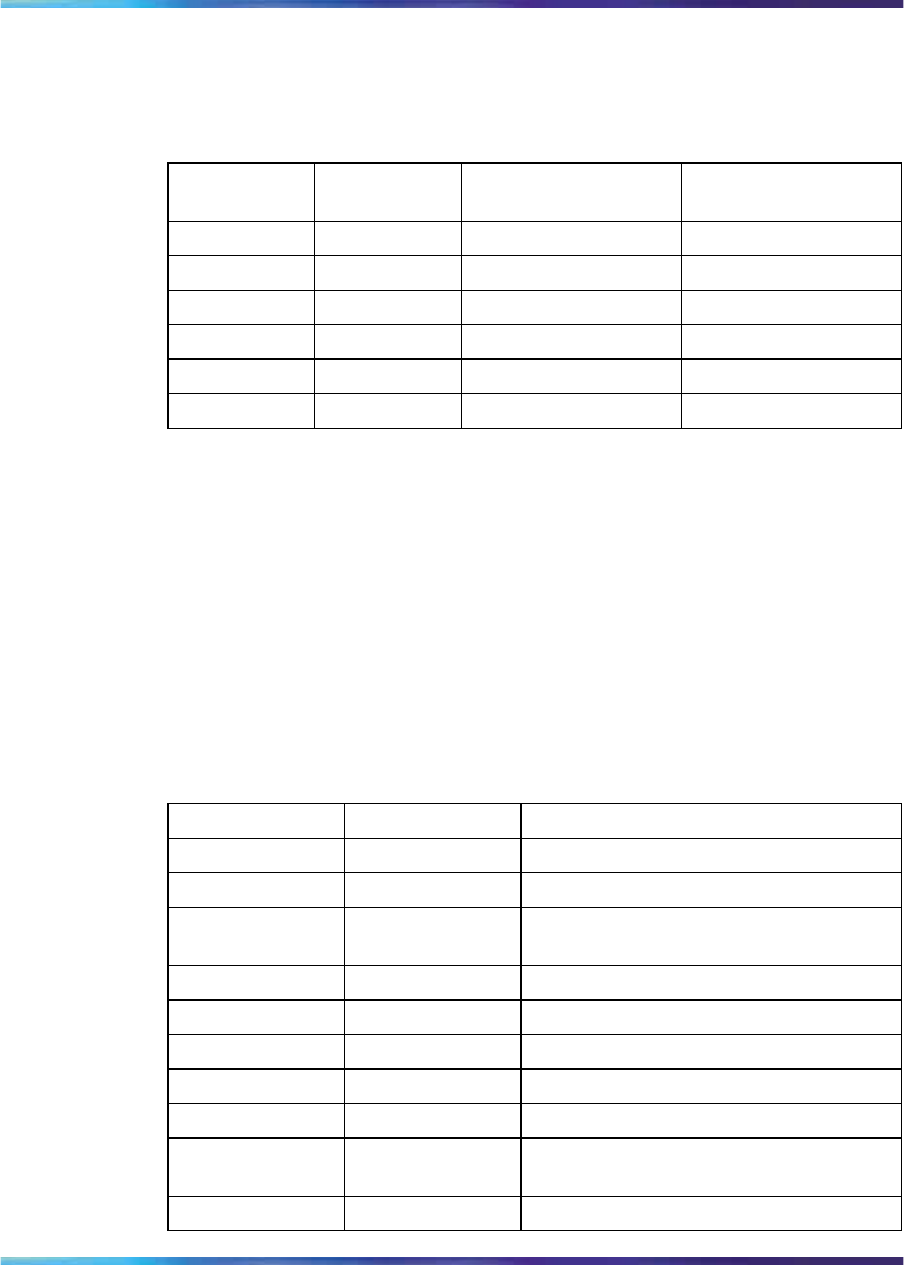
QCAD128 297
•P2 Connector (I/O Panel end) - 9-pin, male, subminiature D, with
jackscrews
Table 108
NT8D7206, NT8D7207 wire list
Color From
(pack end) To
(I/O end) Signal
White P1-1 P2-6 XTIP (transmit)
Black P1-9 P2-7 XRING (transmit)
Green Shield nc P2-CASE P2-9 GROUND
Red P1-3 P2-2 RTIP (receive)
Black P1-11 P2-3 RRING (receive)
Red Shield nc P2-CASE P2-5 GROUND
QCAD128 This cable transports the T1 signal from the PRI pack to the I/O panel.
•Standard length - 10 ft. (3.05 m)
•Construction - 15-conductor ribbon, 28 AWG (0.321 mm), stranded
•P1 Connector - 15-pin, male, subminiature D, with jackscrews
•P2 Connector - 15-pin, male, subminiature D, with jackscrews
See Table Table 109 "QCAD128 wire list" (page 297).
Table 109
QCAD128 wire list
From To Signal
P1-1 P2-1 XTIP (transmit tip) to telephone company
P1-2 P2-2 GND (ground)
P1-3 P2-3 RTIP (receive tip) from telephone
company
P1-4 P2-4 GND (ground)
P1-5 P2-5
P1-6 P2-6
P1-7 P2-7
P1-8 P2-8
P1-9 P2-9 XRING (transmit ring) to telephone
company
P1-10 P2-10
Nortel Communication Server 1000
ISDN Primary Rate Interface Installation and Commissioning
NN43001-301 02.03 Standard
Release 5.5 7 December 2007
Copyright © 2003-2007, Nortel Networks
.
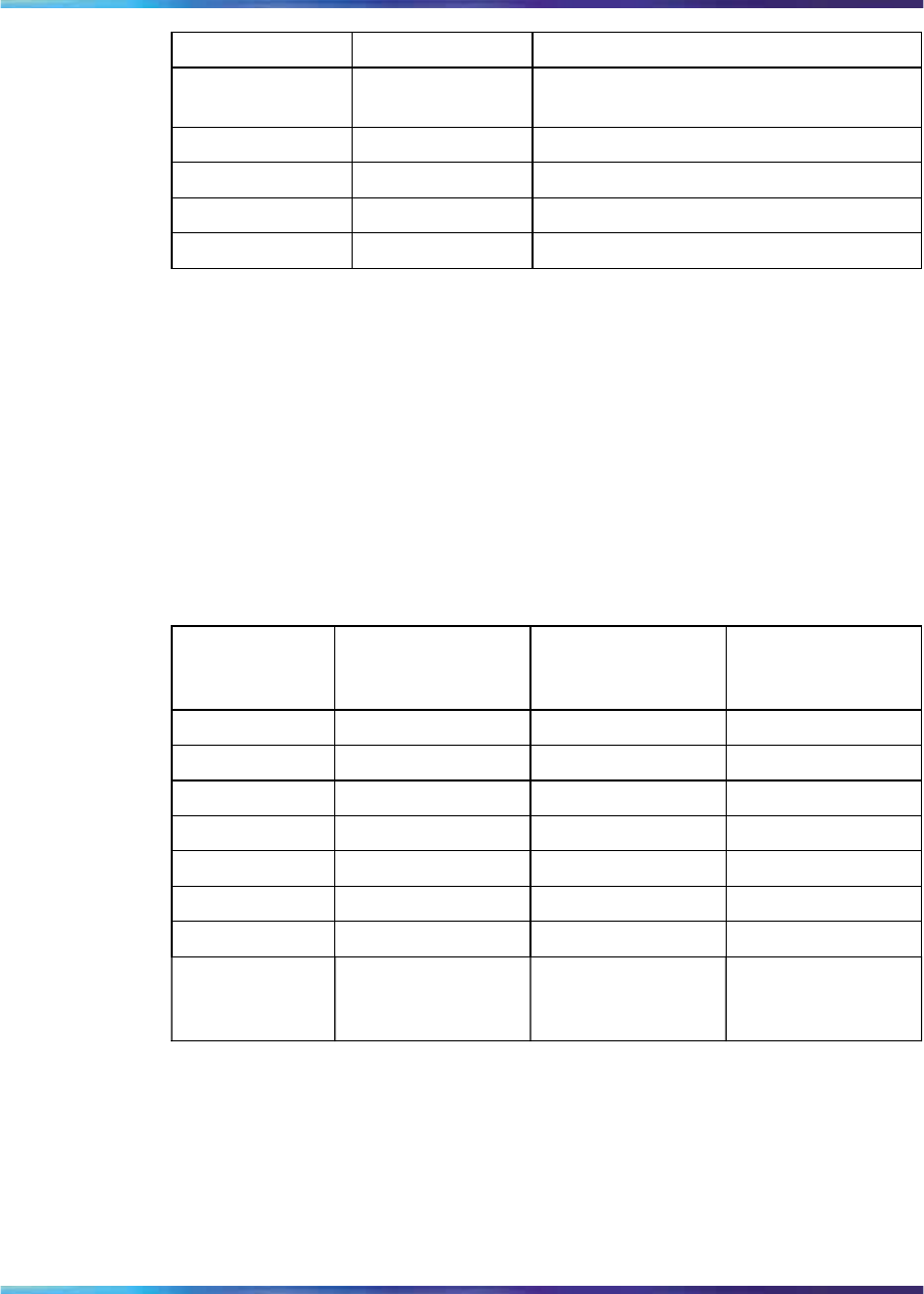
298 Nonstandard cables
From To Signal
P1-11 P2-11 RRING (receive ring) from telephone
company
P1-12 P2-12
P1-13 P2-13
P1-14 P2-14
P1-15 P2-15
QCAD129 This cable is used to connect the RS-232-C interface between an echo
canceller and the PRI pack.
•Standard length - 2.1 m (7 ft.)
•Construction - 22 AWG (0.644 mm), stranded
•P1 Connector - 15-pin, male, subminiature D, with jackscrews
•P2 connector - 25-pin, male, subminiature D, with jackscrews
Table 110
QCAD129 wire list
PRI Signal From To
Echo
Canceller
Signal
DCD P1-1 P2-20 DTR
RXD P1-2 P2-2 TXD
DTR P1-4 P2-8 DCD
TXD P1-5 P2-3 RXD
GND P1-10 P2-7 GND
RTS P1-12 P2-4
CTS P1-9 P2-5
TPENB
(Test Port
Enable Bar)
P1-15 nc
QCAD133 For cabinets with an I/O filter assembly, this cable transports the T1 signal
from the I/O filter to the Network Channel Terminating Equipment (NCTE)
telephone company interface. See Table Table 111 "QCAD133 wire list"
(page 299).
Nortel Communication Server 1000
ISDN Primary Rate Interface Installation and Commissioning
NN43001-301 02.03 Standard
Release 5.5 7 December 2007
Copyright © 2003-2007, Nortel Networks
.

NT8D7205 299
For cabinets without an I/O filter assembly, this cable transports the
T1 signal from the QPC720 PRI pack to the NCTE telephone company
interface.
•Standard length - 50 ft (15.3 m)
•Construction - Individually foil-shielded, twisted pairs, 24 AWG (0.511
mm), stranded
•P1 Connector - 15-pin, female, subminiature D with jackscrews
•P2 Connector - 15-pin, male, subminiature D, with slide-latch (optional
spring-latch loose-packed with cable assembly)
Table 111
QCAD133 wire list
Color From To PRI signal
WHITE P1-1 P2-1 XTIP (transmit tip) to
telephone company
BLACK P1-9 P2-9 XRING (transmit ring) to
telephone company
GRN SHLD P1-2 nc GND (ground)
RED P1-3 P2-3 RTIP (receive tip) from
telephone company
BLACK P1-11 P2-11 RRING (receive ring) from
telephone company
RED SHLD P1-4 nc GND (ground)
NT8D7205 This cable is used to transport the 2Mb digital signal from the I/O panel
at the cabinet bulkhead to the Network Channel Terminating Equipment
(NCTE) telephone company interface.
•Standard length - 15.3 m (50 ft.)
•Construction - Individually foil-shielded, twisted pairs, 24 AWG (0.511
mm), stranded
•P1 Connector - 9-pin, female, subminiature D with jackscrews
•P2 Connector - 9-pin, male, subminiature D, with jack screws
Table 112
NT8D7205 wire list
Color From
(pack end) To
(I/O end) Signal
White P1-6 P2-6 XTIP (transmit)
Nortel Communication Server 1000
ISDN Primary Rate Interface Installation and Commissioning
NN43001-301 02.03 Standard
Release 5.5 7 December 2007
Copyright © 2003-2007, Nortel Networks
.
300 Nonstandard cables
Color From
(pack end) To
(I/O end) Signal
Black P1-7 P2-7 XRING (transmit)
Green Shield P1-9 nc GROUND
Red P1-2 P2-2 RTIP (receive)
Black P1-3 P2-3 RRING (receive)
Red Shield P1-5 nc GROUND
QCAD328 This cable is used to connect the PRI pack to the D-channel interface card,
either the QPC757 or NT6D11AB DCHI. There are two types of QCAD328
cables: QCAD328A and QCAD328B.
•QCAD328A - 1.8 m (6 ft)
•QCAD328B - 5.5 m (18 ft)
•QCAD328C - 10.67 m (35 ft)
•QCAD328D - 15.24 m (50 ft)
•Construction - 24 AWG (0.511 mm), stranded
•P1 Connector - 25-pin male, subminiature D
•P2 Connector - 15-pin male, subminiature D
Table 113
QCAD328 wire list
From To Signal
P1-2 P2-2 SDA+
P1-13 P2-10 SDB-
P1-20 P2-15 TR
P1-15 P2-9 STA+
P1-14 P2-11 STB-
P1-3 P2-4 RDA+
P1-16 P2-12 RDB-
P1-17 P2-5 RTA+
P1-12 P2-13 RTB-
P1-8 P2-8 RR
P1-5 P1-8 CS
P1-7 P1-1 SG
P1-1 P2-1 GND
Nortel Communication Server 1000
ISDN Primary Rate Interface Installation and Commissioning
NN43001-301 02.03 Standard
Release 5.5 7 December 2007
Copyright © 2003-2007, Nortel Networks
.

NT8D83 PRI/DTI to I/O cable 301
NT8D74 Clock Controller to InterGroup cable
This cable connects the QPC471 Clock Controller card to the NT8D36
InterGroup Module.
This cable is available in the following lengths:
•NT8D74AC 1.2 m (4 ft)
•NT8D74AD 1.8 m (6 ft)
•NT8D74AE 2.4 m (8 ft)
•NT8D74AF (QCAD110B) 3 m (10 ft)
•NT8D74AJ 4.8 m (16 ft)
NT8D75 Clock Controller to Clock Controller cable
This cable interconnects QPC471 Clock Controller cards.
This cable is available in the following lengths:
•NT8D75AC 1.2 m (4 ft)
•NT8D75AD 1.8 m (6 ft)
•QCAD125 3 m (10 ft)
NT8D79 PRI/DTI to Clock Controller cable
This cable connects the PRI/DTI card to the QPC471 Clock Controller card.
This cable is available in the following lengths:
•NT8D79AB 0.6 m (2 ft)
•NT8D79AC 1.2 m (4 ft)
•NT8D79AD 1.8 m (6 ft)
•NT8D79AE 2.4 m (8 ft)
•NT8D79AF
(QCAD130) 3 m (10 ft)
NT8D83 PRI/DTI to I/O cable
This cable connects the PRI/DTI card (T1 port) to the I/O connector panel.
This cable is available in the following lengths:
•NT8D83AC 1.2 m (4 ft)
•NT8D83AD 1.8 m (6 ft)
Nortel Communication Server 1000
ISDN Primary Rate Interface Installation and Commissioning
NN43001-301 02.03 Standard
Release 5.5 7 December 2007
Copyright © 2003-2007, Nortel Networks
.

302 Nonstandard cables
NT8D85 Network to IPE cable
This cable connects the following:
•QPC581 CMA card to QPC581 CMA card in dual CPU configuration
•QPC414 Network card to PRI/DTI card
•QPC414 Network card to QPC659 Dual Loop Peripheral Buffer card
(for internal cabling only)
•QPC659 Dual Loop Peripheral Buffer card to QPC659 Dual Loop
Peripheral Buffer card when connecting two NT8D13 IPE Modules
together
This cable is available in the following lengths:
•NT8D85AB 0.6 m (2 ft)
•NT8D85AC 1.2 m (4 ft)
•NT8D85AZ 1.5 m (5 ft)
•NT8D85AD 1.8 m (6 ft)
•NT8D85AE 2.4 m (8 ft)
•NT8D85AF 3 m (10 ft)
•NT8D85AJ 4.8 m (16 ft)
•NT8D85AL 6 m (20 ft)
•NT8D85AP 7.6 m (25 ft)
•NT8D85AV 13.7 m (45 ft)
NT8D86 Network to I/O cable
This cable connects the following to the I/O connector panel:
•QPC414 Network card
•PRI/DTI card
•QPC659 Dual Loop Peripheral Buffer card
•NT8D47 RPE
This cable is available in the following lengths:
•NT8D86AC 1.5 m (5 ft)
•NT8D86AD 1.8 m (6 ft)
NT8D97AX PRI/DTI I/O to MDF cable
This cable connects the PRI/DTI card to the MDF through the I/O connector
panel. It is 15.2 m (50 ft) long.
Nortel Communication Server 1000
ISDN Primary Rate Interface Installation and Commissioning
NN43001-301 02.03 Standard
Release 5.5 7 December 2007
Copyright © 2003-2007, Nortel Networks
.

NTND98 PRI to I/O panel cables 303
NT9J93AD PRI/DTI Echo Canceller to I/O cable
This cable connects the PRI/DTI Echo Canceller port to the I/O connector
panel. It is 1.8 m (6 ft) long.
NTND26 PRI to MSDL cables
These cables connect the MSDL card to the PRI cards.
•NTND26AA 6 feet
•NTND26AB 18 feet
•NTND26AC 35 feet
•NTND26AD 50 feet
NTND27 MSDL to I/O panel cables
These cables connect the MSDL card to the I/O panel.
•NTND27 6 ft
NTND98 PRI to I/O panel cables
These cables connect the PRI card to the I/O panel.
•NTND98 6 ft
Nortel Communication Server 1000
ISDN Primary Rate Interface Installation and Commissioning
NN43001-301 02.03 Standard
Release 5.5 7 December 2007
Copyright © 2003-2007, Nortel Networks
.

304 Nonstandard cables
Nortel Communication Server 1000
ISDN Primary Rate Interface Installation and Commissioning
NN43001-301 02.03 Standard
Release 5.5 7 December 2007
Copyright © 2003-2007, Nortel Networks
.

Nortel Communication Server 1000
ISDN Primary Rate Interface Installation and Commissioning
Copyright © 2003-2007, Nortel Networks
All Rights Reserved.
Publication: NN43001-301
Document status: Standard
Document version: 02.03
Document date: 7 December 2007
To provide feedback or to report a problem with this document, go to www.nortel.com/documentfeedback.
Sourced in Canada
LEGAL NOTICE
While the information in this document is believed to be accurate and reliable, except as otherwise expressly agreed to in writing
NORTEL PROVIDES THIS DOCUMENT "AS IS" WITHOUT WARRANTY OR CONDITION OF ANY KIND, EITHER EXPRESS OR
IMPLIED. The information and/or products described in this document are subject to change without notice.
Nortel, the Nortel Logo, the Globemark, SL-1, Meridian1, and Succession are trademarks of Nortel Networks.
All other trademarks are the property of their respective owners.
