Nortel Networks Nn46110 602 02 01 Users Manual VPN Router Troubleshooting Server
NN46110-602 02.01 to the manual 08e07f69-0b0e-42d1-ae46-6440148e6f83
2015-01-26
: Nortel-Networks Nortel-Networks-Nn46110-602-02-01-Users-Manual-346393 nortel-networks-nn46110-602-02-01-users-manual-346393 nortel-networks pdf
Open the PDF directly: View PDF ![]() .
.
- Nortel VPN Router Troubleshooting - Server
- Contents
- Preface
- New in this release
- Troubleshooting fundamentals
- Troubleshooting tools
- Standard tools
- Client-based tools
- System-based tools
- Configuring core dump retrieval on diskless routers
- Enabling packet capture on a VPN Router
- Saving captured data
- Capturing packets to disk file
- Configure and run packet capture objects
- Sample packet capture configurations
- View a packet capture output file on a PC
- Installing Ethereal software
- Saving, downloading, and viewing PCAP files
- Viewing a PCAP file with Sniffer Pro
- Deleting capture objects and disabling packet capture
- TunnelGuard tools
- IPsec commands
- Other tools
- System configuration
- File management
- Status and logging
- Emergency recovery
- Accessing the diskette drive
- Creating a recovery diskette
- Starting from a recovery diskette
- Using recovery on a diskless system
- Restoring factory defaults or a backup configuration
- Reformatting the hard disk
- Navigating the file system from the recovery diskette
- Viewing the event log from the recovery diskette
- Recovering the V08_00 backup of ldap and config files
- Recovering the pre V08_00 backup of ldap and config files
- Troubleshooting
- Introduction
- Troubleshoot connectivity problems
- Troubleshoot performance problems
- Troubleshoot general problems
- Troubleshooting system messages
- MIB support
- SNMP RFC (request for comments) support
- Novell IPX MIB
- Novell RIP-SAP MIB
- RFC 1213-Network Management of TCP/IP-Based Internets MIB
- RFC 1573-IanaIfType MIB
- RFC 1724-RIP Version 2 MIB Extension
- RFC 1850-OSPF Version 2 Management Information Base
- RFC 2233-If MIB
- RFC2495-DS1 MIB
- RFC 2571-Snmp-Framework MIB
- RFC 2667-IP Tunnel MIB
- RFC 2737-Entity MIB
- RFC 2787-VRRP MIB
- RFC2790-Host Resources MIB
- RFC 2863-Interface MIB (64 bit counters support)
- RFC 2933-Internet Group Management Protocol MIB
- VPN Router MIB
- cestraps.mib-Nortel proprietary MIB
- newoak.mib
- SNMP RFC (request for comments) support
- Index

Version 8.00
Part No. NN46110-602 02.01
315900-F Rev 01
13 October 2008
Document status: Standard
600 Technology Park Drive
Billerica, MA 01821-4130
Nortel VPN Router
Troubleshooting — Server

2
NN46110-602 02.01
Copyright © 2008 Nortel Networks. All rights reserved.
The information in this document is subject to change without notice. The statements, configurations, technical data, and
recommendations in this document are believed to be accurate and reliable, but are presented without express or implied
warranty. Users must take full responsibility for their applications of any products specified in this document. The
information in this document is proprietary to Nortel Networks.
The software described in this document is furnished under a license agreement and may be used only in accordance
with the terms of that license. The software license agreement is included in this document.
Trademarks
Nortel, the Nortel logo, and the Globemark are trademarks of Nortel Networks.
Adobe, Acrobat, and Acrobat Reader are trademarks of Adobe Systems Incorporated.
Macintosh is a trademark of Apple Computer, Inc.
Cisco and Cisco Systems are trademarks of Cisco Technology, Inc.
SafeNet is a trademark of SafeNet, Inc.
Linux is a trademark of Linus Torvalds.
Microsoft, MS-DOS, Windows, and Windows NT are trademarks of Microsoft Corporation.
Netscape and Netscape Communicator are trademarks of Netscape Communications Corporation.
Network General Sniffer is a trademark of Network Associates, Inc.
NetWare, IPX, NetWare, and Novell are trademarks of Novell, Inc.
RSA and SecurID are trademarks of RSA Security Inc.
Java and JavaScript are trademarks of Sun Microsystems, Inc.
All other trademarks are the property of their respective owners.
Restricted rights legend
Use, duplication, or disclosure by the United States Government is subject to restrictions as set forth in subparagraph
(c)(1)(ii) of the Rights in Technical Data and Computer Software clause at DFARS 252.227-7013.
Notwithstanding any other license agreement that may pertain to, or accompany the delivery of, this computer software,
the rights of the United States Government regarding its use, reproduction, and disclosure are as set forth in the
Commercial Computer Software-Restricted Rights clause at FAR 52.227-19.
Statement of conditions
In the interest of improving internal design, operational function, and/or reliability, Nortel Networks Inc. reserves the
right to make changes to the products described in this document without notice.
Nortel Networks Inc. does not assume any liability that may occur due to the use or application of the product(s) or
circuit layout(s) described herein.

3
Nortel VPN Router Troubleshooting — Server
Portions of the code in this software product may be Copyright © 1988, Regents of the University of California. All
rights reserved. Redistribution and use in source and binary forms of such portions are permitted, provided that the
above copyright notice and this paragraph are duplicated in all such forms and that any documentation, advertising
materials, and other materials related to such distribution and use acknowledge that such portions of the software were
developed by the University of California, Berkeley. The name of the University may not be used to endorse or promote
products derived from such portions of the software without specific prior written permission.
SUCH PORTIONS OF THE SOFTWARE ARE PROVIDED “AS IS” AND WITHOUT ANY EXPRESS OR
IMPLIED WARRANTIES, INCLUDING, WITHOUT LIMITATION, THE IMPLIED WARRANTIES OF
MERCHANTABILITY AND FITNESS FOR A PARTICULAR PURPOSE.
In addition, the program and information contained herein are licensed only pursuant to a license agreement that contains
restrictions on use and disclosure (that may incorporate by reference certain limitations and notices imposed by third
parties).
Nortel Networks Inc. software license agreement
This Software License Agreement (“License Agreement”) is between you, the end-user (“Customer”) and Nortel
Networks Corporation and its subsidiaries and affiliates (“Nortel Networks”). PLEASE READ THE FOLLOWING
CAREFULLY. YOU MUST ACCEPT THESE LICENSE TERMS IN ORDER TO DOWNLOAD AND/OR USE THE
SOFTWARE. USE OF THE SOFTWARE CONSTITUTES YOUR ACCEPTANCE OF THIS LICENSE
AGREEMENT. If you do not accept these terms and conditions, return the Software, unused and in the original shipping
container, within 30 days of purchase to obtain a credit for the full purchase price.
“Software” is owned or licensed by Nortel Networks, its parent or one of its subsidiaries or affiliates, and is copyrighted
and licensed, not sold. Software consists of machine-readable instructions, its components, data, audio-visual content
(such as images, text, recordings or pictures) and related licensed materials including all whole or partial copies. Nortel
Networks grants you a license to use the Software only in the country where you acquired the Software. You obtain no
rights other than those granted to you under this License Agreement. You are responsible for the selection of the
Software and for the installation of, use of, and results obtained from the Software.
1. Licensed Use of Software. Nortel Networks grants Customer a nonexclusive license to use a copy of the Software
on only one machine at any one time or to the extent of the activation or authorized usage level, whichever is applicable.
To the extent Software is furnished for use with designated hardware or Customer furnished equipment (“CFE”),
Customer is granted a nonexclusive license to use Software only on such hardware or CFE, as applicable. Software
contains trade secrets and Customer agrees to treat Software as confidential information using the same care and
discretion Customer uses with its own similar information that it does not wish to disclose, publish or disseminate.
Customer will ensure that anyone who uses the Software does so only in compliance with the terms of this Agreement.
Customer shall not a) use, copy, modify, transfer or distribute the Software except as expressly authorized; b) reverse
assemble, reverse compile, reverse engineer or otherwise translate the Software; c) create derivative works or
modifications unless expressly authorized; or d) sublicense, rent or lease the Software. Licensors of intellectual property
to Nortel Networks are beneficiaries of this provision. Upon termination or breach of the license by Customer or in the
event designated hardware or CFE is no longer in use, Customer will promptly return the Software to Nortel Networks
or certify its destruction. Nortel Networks may audit by remote polling or other reasonable means to determine
Customer’s Software activation or usage levels. If suppliers of third party software included in Software require Nortel
Networks to include additional or different terms, Customer agrees to abide by such terms provided by Nortel Networks
with respect to such third party software.
2. Warranty. Except as may be otherwise expressly agreed to in writing between Nortel Networks and Customer,
Software is provided “AS IS” without any warranties (conditions) of any kind. NORTEL NETWORKS DISCLAIMS
ALL WARRANTIES (CONDITIONS) FOR THE SOFTWARE, EITHER EXPRESS OR IMPLIED, INCLUDING,
BUT NOT LIMITED TO THE IMPLIED WARRANTIES OF MERCHANTABILITY AND FITNESS FOR A
PARTICULAR PURPOSE AND ANY WARRANTY OF NON-INFRINGEMENT. Nortel Networks is not obligated to
provide support of any kind for the Software. Some jurisdictions do not allow exclusion of implied warranties, and, in
such event, the above exclusions may not apply.

4
NN46110-602 02.01
3. Limitation of Remedies. IN NO EVENT SHALL NORTEL NETWORKS OR ITS AGENTS OR SUPPLIERS BE
LIABLE FOR ANY OF THE FOLLOWING: a) DAMAGES BASED ON ANY THIRD PARTY CLAIM; b) LOSS OF,
OR DAMAGE TO, CUSTOMER’S RECORDS, FILES OR DATA; OR c) DIRECT, INDIRECT, SPECIAL,
INCIDENTAL, PUNITIVE, OR CONSEQUENTIAL DAMAGES (INCLUDING LOST PROFITS OR SAVINGS),
WHETHER IN CONTRACT, TORT OR OTHERWISE (INCLUDING NEGLIGENCE) ARISING OUT OF YOUR
USE OF THE SOFTWARE, EVEN IF NORTEL NETWORKS, ITS AGENTS OR SUPPLIERS HAVE BEEN
ADVISED OF THEIR POSSIBILITY. The forgoing limitations of remedies also apply to any developer and/or supplier
of the Software. Such developer and/or supplier is an intended beneficiary of this Section. Some jurisdictions do not
allow these limitations or exclusions and, in such event, they may not apply.
4. General
a. If Customer is the United States Government, the following paragraph shall apply: All Nortel Networks
Software available under this License Agreement is commercial computer software and commercial computer
software documentation and, in the event Software is licensed for or on behalf of the United States
Government, the respective rights to the software and software documentation are governed by Nortel
Networks standard commercial license in accordance with U.S. Federal Regulations at 48 C.F.R. Sections
12.212 (for non-DoD entities) and 48 C.F.R. 227.7202 (for DoD entities).
b. Customer may terminate the license at any time. Nortel Networks may terminate the license if Customer fails
to comply with the terms and conditions of this license. In either event, upon termination, Customer must
either return the Software to Nortel Networks or certify its destruction.
c. Customer is responsible for payment of any taxes, including personal property taxes, resulting from
Customer’s use of the Software. Customer agrees to comply with all applicable laws including all applicable
export and import laws and regulations.
d. Neither party may bring an action, regardless of form, more than two years after the cause of the action arose.
e. The terms and conditions of this License Agreement form the complete and exclusive agreement between
Customer and Nortel Networks.
f. This License Agreement is governed by the laws of the country in which Customer acquires the Software. If
the Software is acquired in the United States, then this License Agreement is governed by the laws of the state
of New York.

5
Nortel VPN Router Troubleshooting — Server
Contents
Preface . . . . . . . . . . . . . . . . . . . . . . . . . . . . . . . . . . . . . . . . . . . . . . . . . . . . . . 11
Before you begin . . . . . . . . . . . . . . . . . . . . . . . . . . . . . . . . . . . . . . . . . . . . . . . . . . . . . 11
Text conventions . . . . . . . . . . . . . . . . . . . . . . . . . . . . . . . . . . . . . . . . . . . . . . . . . . . . . . 11
Related publications . . . . . . . . . . . . . . . . . . . . . . . . . . . . . . . . . . . . . . . . . . . . . . . . . . . 14
Hard-copy technical manuals . . . . . . . . . . . . . . . . . . . . . . . . . . . . . . . . . . . . . . . . . . . . 15
How to get help . . . . . . . . . . . . . . . . . . . . . . . . . . . . . . . . . . . . . . . . . . . . . . . . . . . . . . 15
Finding the latest updates on the Nortel Web site . . . . . . . . . . . . . . . . . . . . . . . . . 15
Help from the Nortel Web site . . . . . . . . . . . . . . . . . . . . . . . . . . . . . . . . . . . . . . . . 16
Help over the phone from a Nortel Solutions Center . . . . . . . . . . . . . . . . . . . . . . . 16
Getting help from a specialist by using an Express Routing Code . . . . . . . . . . . . 16
Getting help through a Nortel distributor or reseller . . . . . . . . . . . . . . . . . . . . . . . . 17
New in this release. . . . . . . . . . . . . . . . . . . . . . . . . . . . . . . . . . . . . . . . . . . . . 19
Features . . . . . . . . . . . . . . . . . . . . . . . . . . . . . . . . . . . . . . . . . . . . . . . . . . . . . . . . . . . .19
Branch office NAT Traversal . . . . . . . . . . . . . . . . . . . . . . . . . . . . . . . . . . . . . . . . . . 19
Core dump retrieval . . . . . . . . . . . . . . . . . . . . . . . . . . . . . . . . . . . . . . . . . . . . . . . . 20
Hardware LEDs . . . . . . . . . . . . . . . . . . . . . . . . . . . . . . . . . . . . . . . . . . . . . . . . . . . 20
IGMP . . . . . . . . . . . . . . . . . . . . . . . . . . . . . . . . . . . . . . . . . . . . . . . . . . . . . . . . . . . 20
LDAP problems . . . . . . . . . . . . . . . . . . . . . . . . . . . . . . . . . . . . . . . . . . . . . . . . . . . 20
Recovery procedures . . . . . . . . . . . . . . . . . . . . . . . . . . . . . . . . . . . . . . . . . . . . . . 20
SFTP . . . . . . . . . . . . . . . . . . . . . . . . . . . . . . . . . . . . . . . . . . . . . . . . . . . . . . . . . . . 20
System messages . . . . . . . . . . . . . . . . . . . . . . . . . . . . . . . . . . . . . . . . . . . . . . . . . 20
Supported software and hardware . . . . . . . . . . . . . . . . . . . . . . . . . . . . . . . . . . . . 21
Two factor authentication . . . . . . . . . . . . . . . . . . . . . . . . . . . . . . . . . . . . . . . . . . . . 21
Other changes . . . . . . . . . . . . . . . . . . . . . . . . . . . . . . . . . . . . . . . . . . . . . . . . . . . . . . . 21
Removed content . . . . . . . . . . . . . . . . . . . . . . . . . . . . . . . . . . . . . . . . . . . . . . . . . . 21
Restructured content . . . . . . . . . . . . . . . . . . . . . . . . . . . . . . . . . . . . . . . . . . . . . . . 22
Title change . . . . . . . . . . . . . . . . . . . . . . . . . . . . . . . . . . . . . . . . . . . . . . . . . . . . . . 22

6Contents
NN46110-602 02.01
Chapter 1
Troubleshooting fundamentals. . . . . . . . . . . . . . . . . . . . . . . . . . . . . . . . . . . 23
Supported software and hardware . . . . . . . . . . . . . . . . . . . . . . . . . . . . . . . . . . . . . . . . 23
PCAP . . . . . . . . . . . . . . . . . . . . . . . . . . . . . . . . . . . . . . . . . . . . . . . . . . . . . . . . . . . . . .33
PCAP features . . . . . . . . . . . . . . . . . . . . . . . . . . . . . . . . . . . . . . . . . . . . . . . . . . . . 34
Security features . . . . . . . . . . . . . . . . . . . . . . . . . . . . . . . . . . . . . . . . . . . . . . . 35
File format . . . . . . . . . . . . . . . . . . . . . . . . . . . . . . . . . . . . . . . . . . . . . . . . . . . . . . . 35
Capture types . . . . . . . . . . . . . . . . . . . . . . . . . . . . . . . . . . . . . . . . . . . . . . . . . . . . 36
Physical interface captures . . . . . . . . . . . . . . . . . . . . . . . . . . . . . . . . . . . . . . . 36
Tunnel captures . . . . . . . . . . . . . . . . . . . . . . . . . . . . . . . . . . . . . . . . . . . . . . . . 36
Global IP captures . . . . . . . . . . . . . . . . . . . . . . . . . . . . . . . . . . . . . . . . . . . . . . 37
Filters and triggers . . . . . . . . . . . . . . . . . . . . . . . . . . . . . . . . . . . . . . . . . . . . . . . . . 38
Capture filters . . . . . . . . . . . . . . . . . . . . . . . . . . . . . . . . . . . . . . . . . . . . . . . . . 38
Triggers . . . . . . . . . . . . . . . . . . . . . . . . . . . . . . . . . . . . . . . . . . . . . . . . . . . . . . 38
Memory considerations . . . . . . . . . . . . . . . . . . . . . . . . . . . . . . . . . . . . . . . . . . . . . 39
Performance considerations . . . . . . . . . . . . . . . . . . . . . . . . . . . . . . . . . . . . . . . . . 40
Hardware LEDs . . . . . . . . . . . . . . . . . . . . . . . . . . . . . . . . . . . . . . . . . . . . . . . . . . . . . . 40
Chapter 2
Troubleshooting tools . . . . . . . . . . . . . . . . . . . . . . . . . . . . . . . . . . . . . . . . . . 51
Standard tools . . . . . . . . . . . . . . . . . . . . . . . . . . . . . . . . . . . . . . . . . . . . . . . . . . . . . . . 51
Ping . . . . . . . . . . . . . . . . . . . . . . . . . . . . . . . . . . . . . . . . . . . . . . . . . . . . . . . . . . . . 51
Traceroute . . . . . . . . . . . . . . . . . . . . . . . . . . . . . . . . . . . . . . . . . . . . . . . . . . . . . . . 52
mtrace . . . . . . . . . . . . . . . . . . . . . . . . . . . . . . . . . . . . . . . . . . . . . . . . . . . . . . . . . . 53
ARP . . . . . . . . . . . . . . . . . . . . . . . . . . . . . . . . . . . . . . . . . . . . . . . . . . . . . . . . . . . . 56
Client-based tools . . . . . . . . . . . . . . . . . . . . . . . . . . . . . . . . . . . . . . . . . . . . . . . . . . . . 57
System-based tools . . . . . . . . . . . . . . . . . . . . . . . . . . . . . . . . . . . . . . . . . . . . . . . . . . . 57
Configuring core dump retrieval on diskless routers . . . . . . . . . . . . . . . . . . . . . . . 57
Enabling packet capture on a VPN Router . . . . . . . . . . . . . . . . . . . . . . . . . . . . . . 58
Saving captured data . . . . . . . . . . . . . . . . . . . . . . . . . . . . . . . . . . . . . . . . . . . . . . . 60
Capturing packets to disk file . . . . . . . . . . . . . . . . . . . . . . . . . . . . . . . . . . . . . . . . . 61
Setting the PCAP file path . . . . . . . . . . . . . . . . . . . . . . . . . . . . . . . . . . . . . . . . 61
Setting the size of the RAM buffer . . . . . . . . . . . . . . . . . . . . . . . . . . . . . . . . . . 61
Setting the size of a disk capture file . . . . . . . . . . . . . . . . . . . . . . . . . . . . . . . . 62
Setting the maximum number of disk capture files . . . . . . . . . . . . . . . . . . . . . 62

Contents 7
Nortel VPN Router Troubleshooting — Server
Saving captured data . . . . . . . . . . . . . . . . . . . . . . . . . . . . . . . . . . . . . . . . . . . 62
Configure and run packet capture objects . . . . . . . . . . . . . . . . . . . . . . . . . . . . . . . 63
Creating a capture object . . . . . . . . . . . . . . . . . . . . . . . . . . . . . . . . . . . . . . . . 63
Configuring a capture object . . . . . . . . . . . . . . . . . . . . . . . . . . . . . . . . . . . . . . 64
Starting, stopping, and saving capture objects . . . . . . . . . . . . . . . . . . . . . . . . 67
Displaying capture status . . . . . . . . . . . . . . . . . . . . . . . . . . . . . . . . . . . . . . . . 67
Sample packet capture configurations . . . . . . . . . . . . . . . . . . . . . . . . . . . . . . . . . . 69
Interface capture object using a filter and direction . . . . . . . . . . . . . . . . . . . . . 69
Interface capture object using triggers . . . . . . . . . . . . . . . . . . . . . . . . . . . . . . 70
Tunnel capture object using a remote IP address . . . . . . . . . . . . . . . . . . . . . . 73
View a packet capture output file on a PC . . . . . . . . . . . . . . . . . . . . . . . . . . . . . . . 74
Installing Ethereal software . . . . . . . . . . . . . . . . . . . . . . . . . . . . . . . . . . . . . . . . . . 74
Saving, downloading, and viewing PCAP files . . . . . . . . . . . . . . . . . . . . . . . . . . . 74
Viewing a PCAP file with Sniffer Pro . . . . . . . . . . . . . . . . . . . . . . . . . . . . . . . . . . . 75
Deleting capture objects and disabling packet capture . . . . . . . . . . . . . . . . . . . . . 77
TunnelGuard tools . . . . . . . . . . . . . . . . . . . . . . . . . . . . . . . . . . . . . . . . . . . . . . . . . 78
IPsec commands . . . . . . . . . . . . . . . . . . . . . . . . . . . . . . . . . . . . . . . . . . . . . . . . . . 78
Other tools . . . . . . . . . . . . . . . . . . . . . . . . . . . . . . . . . . . . . . . . . . . . . . . . . . . . . . . . . .79
System configuration . . . . . . . . . . . . . . . . . . . . . . . . . . . . . . . . . . . . . . . . . . . . . . . . . . 79
File management . . . . . . . . . . . . . . . . . . . . . . . . . . . . . . . . . . . . . . . . . . . . . . . . . . . . . 79
Chapter 3
Status and logging. . . . . . . . . . . . . . . . . . . . . . . . . . . . . . . . . . . . . . . . . . . . . 81
Introduction . . . . . . . . . . . . . . . . . . . . . . . . . . . . . . . . . . . . . . . . . . . . . . . . . . . . . . . . . 81
Sessions . . . . . . . . . . . . . . . . . . . . . . . . . . . . . . . . . . . . . . . . . . . . . . . . . . . . . . . . . . . .82
Reports . . . . . . . . . . . . . . . . . . . . . . . . . . . . . . . . . . . . . . . . . . . . . . . . . . . . . . . . . . . .82
System . . . . . . . . . . . . . . . . . . . . . . . . . . . . . . . . . . . . . . . . . . . . . . . . . . . . . . . . . . . . .83
Health check . . . . . . . . . . . . . . . . . . . . . . . . . . . . . . . . . . . . . . . . . . . . . . . . . . . . . . . . 83
Statistics . . . . . . . . . . . . . . . . . . . . . . . . . . . . . . . . . . . . . . . . . . . . . . . . . . . . . . . . . . . . 83
Accounting . . . . . . . . . . . . . . . . . . . . . . . . . . . . . . . . . . . . . . . . . . . . . . . . . . . . . . . . . . 84
Accounting records . . . . . . . . . . . . . . . . . . . . . . . . . . . . . . . . . . . . . . . . . . . . . . . . 84
RADIUS accounting . . . . . . . . . . . . . . . . . . . . . . . . . . . . . . . . . . . . . . . . . . . . . . . . 85
Data collection task . . . . . . . . . . . . . . . . . . . . . . . . . . . . . . . . . . . . . . . . . . . . . . . . 85
Logs . . . . . . . . . . . . . . . . . . . . . . . . . . . . . . . . . . . . . . . . . . . . . . . . . . . . . . . . . . . . . . . 87
Event log . . . . . . . . . . . . . . . . . . . . . . . . . . . . . . . . . . . . . . . . . . . . . . . . . . . . . . . . 87

8Contents
NN46110-602 02.01
System log . . . . . . . . . . . . . . . . . . . . . . . . . . . . . . . . . . . . . . . . . . . . . . . . . . . . . . . 89
Security log . . . . . . . . . . . . . . . . . . . . . . . . . . . . . . . . . . . . . . . . . . . . . . . . . . . . . . 89
Configuration log . . . . . . . . . . . . . . . . . . . . . . . . . . . . . . . . . . . . . . . . . . . . . . . . . . 90
Chapter 4
Emergency recovery . . . . . . . . . . . . . . . . . . . . . . . . . . . . . . . . . . . . . . . . . . . 91
Accessing the diskette drive . . . . . . . . . . . . . . . . . . . . . . . . . . . . . . . . . . . . . . . . . . . . . 92
Creating a recovery diskette . . . . . . . . . . . . . . . . . . . . . . . . . . . . . . . . . . . . . . . . . . . . 92
Starting from a recovery diskette . . . . . . . . . . . . . . . . . . . . . . . . . . . . . . . . . . . . . . . . . 93
Using recovery on a diskless system . . . . . . . . . . . . . . . . . . . . . . . . . . . . . . . . . . . . . . 93
Restoring factory defaults or a backup configuration . . . . . . . . . . . . . . . . . . . . . . . . . . 94
Reformatting the hard disk . . . . . . . . . . . . . . . . . . . . . . . . . . . . . . . . . . . . . . . . . . . . . . 95
Navigating the file system from the recovery diskette . . . . . . . . . . . . . . . . . . . . . . . . . 97
Viewing the event log from the recovery diskette . . . . . . . . . . . . . . . . . . . . . . . . . . . . . 97
Recovering the V08_00 backup of ldap and config files . . . . . . . . . . . . . . . . . . . . . . . 97
Recovering the pre V08_00 backup of ldap and config files . . . . . . . . . . . . . . . . . . . . 98
Chapter 5
Troubleshooting . . . . . . . . . . . . . . . . . . . . . . . . . . . . . . . . . . . . . . . . . . . . . . . 99
Introduction . . . . . . . . . . . . . . . . . . . . . . . . . . . . . . . . . . . . . . . . . . . . . . . . . . . . . . . . . 99
Troubleshoot connectivity problems . . . . . . . . . . . . . . . . . . . . . . . . . . . . . . . . . . . . . . 100
Client connection problems . . . . . . . . . . . . . . . . . . . . . . . . . . . . . . . . . . . . . . . . . 101
Serial PPP problems . . . . . . . . . . . . . . . . . . . . . . . . . . . . . . . . . . . . . . . . . . . . . . 102
SFTP connection problems . . . . . . . . . . . . . . . . . . . . . . . . . . . . . . . . . . . . . . . . . 104
Branch office connection problems . . . . . . . . . . . . . . . . . . . . . . . . . . . . . . . . . . . 104
DNS name resolution problems . . . . . . . . . . . . . . . . . . . . . . . . . . . . . . . . . . . . . . 104
Network browsing problems . . . . . . . . . . . . . . . . . . . . . . . . . . . . . . . . . . . . . . . . 105
Diagnosing WAN link problems . . . . . . . . . . . . . . . . . . . . . . . . . . . . . . . . . . . . . . 107
Hardware encryption accelerator connectivity . . . . . . . . . . . . . . . . . . . . . . . . . . . 109
Troubleshoot performance problems . . . . . . . . . . . . . . . . . . . . . . . . . . . . . . . . . . . . . 109
Eliminating modem errors . . . . . . . . . . . . . . . . . . . . . . . . . . . . . . . . . . . . . . . . . . 109
Performance tips for configuring Microsoft networking . . . . . . . . . . . . . . . . . . . . 110
Additional information . . . . . . . . . . . . . . . . . . . . . . . . . . . . . . . . . . . . . . . . . . . . . 119
Troubleshoot general problems . . . . . . . . . . . . . . . . . . . . . . . . . . . . . . . . . . . . . . . . . 119
Web browser problems and the Nortel VPN Client Manager . . . . . . . . . . . . . . . 120

Contents 9
Nortel VPN Router Troubleshooting — Server
Enabling Web browser options . . . . . . . . . . . . . . . . . . . . . . . . . . . . . . . . . . . . . . 120
Web browser error messages . . . . . . . . . . . . . . . . . . . . . . . . . . . . . . . . . . . . . . . 122
Reporting a problem with a Web browser . . . . . . . . . . . . . . . . . . . . . . . . . . . . . . 124
System problems . . . . . . . . . . . . . . . . . . . . . . . . . . . . . . . . . . . . . . . . . . . . . . . . . 124
Solving routing problems . . . . . . . . . . . . . . . . . . . . . . . . . . . . . . . . . . . . . . . . . . . 126
Solving firewall problems . . . . . . . . . . . . . . . . . . . . . . . . . . . . . . . . . . . . . . . . . . . 129
An error occurred while parsing the policy . . . . . . . . . . . . . . . . . . . . . . . . . . 129
An error occurred while communicating with the VPN Router . . . . . . . . . . . 129
Authorization failed. Please try again. . . . . . . . . . . . . . . . . . . . . . . . . . . . . . . 130
Unable to communicate with the VPN Router . . . . . . . . . . . . . . . . . . . . . . . . 130
The contents of the database may have changed . . . . . . . . . . . . . . . . . . . . 130
System files were not loaded properly . . . . . . . . . . . . . . . . . . . . . . . . . . . . . 131
Diagnosing LDAP problems . . . . . . . . . . . . . . . . . . . . . . . . . . . . . . . . . . . . . . . . . 132
Chapter 6
Troubleshooting system messages . . . . . . . . . . . . . . . . . . . . . . . . . . . . . . 135
Certificate messages . . . . . . . . . . . . . . . . . . . . . . . . . . . . . . . . . . . . . . . . . . . . . . . . . 136
ISAKMP messages . . . . . . . . . . . . . . . . . . . . . . . . . . . . . . . . . . . . . . . . . . . . . . . . . . 137
IPsec messages . . . . . . . . . . . . . . . . . . . . . . . . . . . . . . . . . . . . . . . . . . . . . . . . . . . . . 142
Branch office messages . . . . . . . . . . . . . . . . . . . . . . . . . . . . . . . . . . . . . . . . . . . . . . . 143
User tunnel messages . . . . . . . . . . . . . . . . . . . . . . . . . . . . . . . . . . . . . . . . . . . . . . . . 145
SSL messages . . . . . . . . . . . . . . . . . . . . . . . . . . . . . . . . . . . . . . . . . . . . . . . . . . . . . . 146
Database messages . . . . . . . . . . . . . . . . . . . . . . . . . . . . . . . . . . . . . . . . . . . . . . . . . 147
Security messages . . . . . . . . . . . . . . . . . . . . . . . . . . . . . . . . . . . . . . . . . . . . . . . . . . . 148
RADIUS accounting messages . . . . . . . . . . . . . . . . . . . . . . . . . . . . . . . . . . . . . . . . . 159
RADIUS authentication messages . . . . . . . . . . . . . . . . . . . . . . . . . . . . . . . . . . . . . . . 162
Routing messages . . . . . . . . . . . . . . . . . . . . . . . . . . . . . . . . . . . . . . . . . . . . . . . . . . . 167
PPP messages . . . . . . . . . . . . . . . . . . . . . . . . . . . . . . . . . . . . . . . . . . . . . . . . . . . . . . 174
Hardware messages . . . . . . . . . . . . . . . . . . . . . . . . . . . . . . . . . . . . . . . . . . . . . . . . . 175
Management messages . . . . . . . . . . . . . . . . . . . . . . . . . . . . . . . . . . . . . . . . . . . . . . . 177
DNS messages . . . . . . . . . . . . . . . . . . . . . . . . . . . . . . . . . . . . . . . . . . . . . . . . . . . . . 178
Appendix A
MIB support . . . . . . . . . . . . . . . . . . . . . . . . . . . . . . . . . . . . . . . . . . . . . . . . . 179
SNMP RFC (request for comments) support . . . . . . . . . . . . . . . . . . . . . . . . . . . . . . . 179

10 Contents
NN46110-602 02.01
Novell IPX MIB . . . . . . . . . . . . . . . . . . . . . . . . . . . . . . . . . . . . . . . . . . . . . . . . . . . 179
Novell RIP-SAP MIB . . . . . . . . . . . . . . . . . . . . . . . . . . . . . . . . . . . . . . . . . . . . . . 179
RFC 1213—Network Management of TCP/IP-Based Internets MIB . . . . . . . . . . 180
RFC 1573—IanaIfType MIB . . . . . . . . . . . . . . . . . . . . . . . . . . . . . . . . . . . . . . . . . 180
RFC 1724—RIP Version 2 MIB Extension . . . . . . . . . . . . . . . . . . . . . . . . . . . . . . 180
RFC 1850—OSPF Version 2 Management Information Base . . . . . . . . . . . . . . . 181
RFC 2233—If MIB . . . . . . . . . . . . . . . . . . . . . . . . . . . . . . . . . . . . . . . . . . . . . . . . 181
RFC2495—DS1 MIB . . . . . . . . . . . . . . . . . . . . . . . . . . . . . . . . . . . . . . . . . . . . . . 181
RFC 2571—Snmp-Framework MIB . . . . . . . . . . . . . . . . . . . . . . . . . . . . . . . . . . . 181
RFC 2667—IP Tunnel MIB . . . . . . . . . . . . . . . . . . . . . . . . . . . . . . . . . . . . . . . . . 181
RFC 2737—Entity MIB . . . . . . . . . . . . . . . . . . . . . . . . . . . . . . . . . . . . . . . . . . . . 182
RFC 2787—VRRP MIB . . . . . . . . . . . . . . . . . . . . . . . . . . . . . . . . . . . . . . . . . . . . 182
RFC2790—Host Resources MIB . . . . . . . . . . . . . . . . . . . . . . . . . . . . . . . . . . . . . 183
RFC 2863—Interface MIB (64 bit counters support) . . . . . . . . . . . . . . . . . . . . . . 184
RFC 2933—Internet Group Management Protocol MIB . . . . . . . . . . . . . . . . . . . 184
VPN Router MIB . . . . . . . . . . . . . . . . . . . . . . . . . . . . . . . . . . . . . . . . . . . . . . . . . 184
cestraps.mib—Nortel proprietary MIB . . . . . . . . . . . . . . . . . . . . . . . . . . . . . . . . . . . . 186
newoak.mib . . . . . . . . . . . . . . . . . . . . . . . . . . . . . . . . . . . . . . . . . . . . . . . . . . . . . . . . 188
Hardware-related traps . . . . . . . . . . . . . . . . . . . . . . . . . . . . . . . . . . . . . . . . . . . . 190
Server-related traps . . . . . . . . . . . . . . . . . . . . . . . . . . . . . . . . . . . . . . . . . . . . . . . 194
Software-related traps . . . . . . . . . . . . . . . . . . . . . . . . . . . . . . . . . . . . . . . . . . . . . 196
Login-related traps . . . . . . . . . . . . . . . . . . . . . . . . . . . . . . . . . . . . . . . . . . . . . . . . 196
Intrusion-related traps . . . . . . . . . . . . . . . . . . . . . . . . . . . . . . . . . . . . . . . . . . . . . 197
System-related traps . . . . . . . . . . . . . . . . . . . . . . . . . . . . . . . . . . . . . . . . . . . . . . 197
Information passed with every trap . . . . . . . . . . . . . . . . . . . . . . . . . . . . . . . . . . . 198
Index . . . . . . . . . . . . . . . . . . . . . . . . . . . . . . . . . . . . . . . . . . . . . . . . . . . . . . . 221

11
Nortel VPN Router Troubleshooting — Server
Preface
This guide provides information about how to manage and troubleshoot the Nortel
VPN Router.
Before you begin
This guide is for network managers who monitor and maintain the Nortel VPN
Router. This guide assumes that you have experience with system administration
and familiarity with network management.
Text conventions
This guide uses the following text conventions:
angle brackets (< >) Indicate that you choose the text to enter based on the
description inside the brackets. Do not type the
brackets when entering the command.
Example: If the command syntax is
ping <ip_address>, you enter
ping 192.32.10.12
bold Courier text Indicates command names and options and text that
you need to enter.
Example: Use the show health command.
Example: Enter terminal paging {off | on}.

12 Preface
NN46110-602 02.01
braces ({}) Indicate required elements in syntax descriptions where
there is more than one option. You must choose only
one of the options. Do not type the braces when
entering the command.
Example: If the command syntax is ldap-server
source {external | internal}, you must enter
either ldap-server source external or
ldap-server source internal, but not both.
brackets ([ ]) Indicate optional elements in syntax descriptions. Do
not type the brackets when entering the command.
Example: If the command syntax is
show ntp [associations], you can enter
either show ntp or show ntp associations.
Example: If the command syntax is default rsvp
[token-bucket {depth | rate}], you can enter
default rsvp, default rsvp token-bucket
depth, or default rsvp token-bucket rate.
ellipsis points (. . .) Indicate that you repeat the last element of the
command as needed.
Example: If the command syntax is
more diskn:<directory>/...<file_name>,
you enter more and the fully qualified name of the file.
italic text Indicates new terms, book titles, and variables in
command syntax descriptions. Where a variable is two
or more words, the words are connected by an
underscore.
Example: If the command syntax is
ping <ip_address>, ip_address is one variable
and you substitute one value for it.
plain Courier
text Indicates system output, for example, prompts and
system messages.
Example: File not found.
separator (,) Shows menu paths.
Example: Choose Status, Health Check.

Preface 13
Nortel VPN Router Troubleshooting — Server
vertical line ( | ) Separates choices for command keywords and
arguments. Enter only one of the choices. Do not type
the vertical line when entering the command.
Example: If the command syntax is
terminal paging {off | on}, you enter either
terminal paging off or terminal paging on,
but not both.

14 Preface
NN46110-602 02.01
Related publications
For more information about the Nortel VPN Router, see the following
publications:
• Release notes provide the latest information, including brief descriptions of
the new features, problems fixed in this release, and known problems and
workarounds.
•Nortel VPN Router Configuration — Basic Features (NN46110-500)
introduces the product and provides information about initial setup and
configuration.
•Nortel VPN Router Configuration — SSL VPN Services (NN46110-501)
provides instructions for configuring services on the SSL VPN Module 1000,
including authentication, networks, user groups, and portal links.
•Nortel VPN Router Security — Servers, Authentication, and Certificates
(NN46110-600) provides instructions for configuring authentication services
and digital certificates.
•Nortel VPN Router Security — Firewalls, Filters, NAT, and QoS
(NN46110-601) provides instructions for configuring the Stateful Firewall
and VPN Router interface and tunnel filters.
•Nortel VPN Router Configuration — Advanced Features (NN46110-502)
provides instructions for configuring advanced LAN and WAN settings, PPP,
frame relay, PPPoE, ADSL and ATM, T1CSU/DSU, dial services and BIS,
DLSw, IPX, and SSL VPN.
• Nortel VPN Router Configuration — Tunneling Protocols (NN46110-503)
configuration information for the tunneling protocols IPsec, L2TP, PPTP, and
L2F.
•Nortel VPN Router Configuration—Routing (NN46110-504) provides
instructions for configuring RIP, OSPF, and VRRP, as well as instructions for
configuring ECMP, routing policy services, and client address redistribution
(CAR).
•Nortel VPN Router Using the Command Line Interface (NN46110-507)
provides syntax, descriptions, and examples for the commands that you can
use from the command line interface.
• Nortel VPN Router Configuration — TunnelGuard (NN46110-307) provides
information about configuring and using the TunnelGuard feature.

Preface 15
Nortel VPN Router Troubleshooting — Server
Hard-copy technical manuals
You can print selected technical manuals and release notes free, directly from the
Internet. Go to www.nortelnetworks.com/documentation, find the product for
which you need documentation, then locate the specific category and model or
version for your hardware or software product. Use Adobe Reader to open the
manuals and release notes, search for the sections you need, and print them on
most standard printers. Go to the Adobe Web site at the www.adobe.com to
download a free copy of the Adobe Reader.
How to get help
This section explains how to get help for Nortel products and services.
Finding the latest updates on the Nortel Web site
The content of this documentation was current at the time the product was
released. To check for updates to the latest documentation and software for VPN
Router, click one of the following links:
Link Website
Latest software Nortel page for VPN Router software located at:
support.nortel.com/go/
main.jsp?cscat=SOFTWARE&poid=12325
Latest
documentation Nortel page for VPN Router documentation located
at:
support.nortel.com/go/
main.jsp?cscat=DOCUMENTATION&poid=12325

16 Preface
NN46110-602 02.01
Help from the Nortel Web site
The best way to get technical support for Nortel products is from the Nortel
Technical Support Web site:
www.nortel.com/support
This site provides quick access to software, documentation, bulletins, and tools to
address issues with Nortel products. From this site, you can
• download software, documentation, and product bulletins
• search the Technical Support Web site and the Nortel Knowledge Base for
answers to technical issues
• sign up for automatic notification of new software and documentation for
Nortel equipment
• open and manage technical support cases
Help over the phone from a Nortel Solutions Center
If you do not find the information you require on the Nortel Technical Support
Web site, and you have a Nortel support contract, you can also get help over the
phone from a Nortel Solutions Center.
In North America, call 1-800-4NORTEL (1-800-466-7835).
Outside North America, go to the following Web site to obtain the phone number
for your region:
www.nortel.com/callus
Getting help from a specialist by using an Express Routing
Code
To access some Nortel Technical Solutions Centers, you can use an Express
Routing Code (ERC) to quickly route your call to a specialist in your Nortel
product or service. To locate the ERC for your product or service, go to
www.nortel.com/erc

Preface 17
Nortel VPN Router Troubleshooting — Server
Getting help through a Nortel distributor or reseller
If you purchased a service contract for your Nortel product from a distributor or
authorized reseller, contact the technical support staff for that distributor or
reseller.

18 Preface
NN46110-602 02.01

19
Nortel VPN Router Troubleshooting — Server
New in this release
The following sections detail what’s new in Nortel VPN Router Troubleshooting
— Server (NN46110-602) for Release 8.0:
•“Features” on page 19
•“Other changes” on page 21
Features
See the following sections for information about feature changes:
•“Branch office NAT Traversal” on page 19
•“Core dump retrieval” on page 20
•“Hardware LEDs” on page 20
•“IGMP” on page 20
•“LDAP problems” on page 20
•“Recovery procedures” on page 20
•“SFTP” on page 20
•“System messages” on page 20
•“Supported software and hardware” on page 21
•“Two factor authentication” on page 21
Branch office NAT Traversal
Release 8.0 includes Network Address Translation (NAT) Traversal for branch
office connections. For more information about how to troubleshoot NAT
Traversal on branch office tunnels, see “Troubleshoot connectivity problems” on
page 100.

20 New in this release
NN46110-602 02.01
Core dump retrieval
“Configuring core dump retrieval on diskless routers” on page 57 is added to the
document.
Hardware LEDs
This document provides a list of hardware LEDs. For more information, see
“Hardware LEDs” on page 40.
IGMP
Release 8.0 includes the Internet Group Management Protocol (IGMP). For more
information about how to troubleshoot IGMP, see “Troubleshooting tools” on
page 51 and “Solving routing problems” on page 126. For information about the
supported management information base (MIB), see “MIB support” on page 179.
LDAP problems
“Diagnosing LDAP problems” on page 132 is added to the document.
Recovery procedures
“Emergency recovery” on page 91 is updated with “Recovering the V08_00
backup of ldap and config files” on page 97 and “Recovering the pre V08_00
backup of ldap and config files” on page 98.
SFTP
Release 8.0 supports the Secure File Transfer Protocol (SFTP). For information
about how to troubleshoot SFTP, see “SFTP” on page 20.
System messages
“Troubleshooting system messages” on page 135 is updated to include more
system messages.

New in this release 21
Nortel VPN Router Troubleshooting — Server
Supported software and hardware
This document includes a matrix of features by release. For more information, see
“Supported software and hardware” on page 23.
Two factor authentication
Release 8.0 includes two factor authentication for branch office and user tunnels.
For more information about how to troubleshoot branch office tunnels, see
“Branch office connection problems” on page 104. For more information about
how to troubleshoot user tunnels, see Nortel VPN Router Troubleshooting —
Client (NN46110-700).
Other changes
See the following sections for information about changes that are not
feature-related:
•“Removed content” on page 21
•“Restructured content” on page 22
•“Title change” on page 22
Removed content
The content in Appendix D Configuring for interoperability is moved to Nortel
VPN Router Configuration — Advanced Features (NN46110-502).
Content about software upgrade is moved to Nortel VPN Router Configuration
Upgrades — Server Software Release 8.0 (NN46110-407).
The following topics are moved to Nortel VPN Router Administration
(NN46110-603):
• administrator settings
• lost user names and passwords
• dynamic passwords

22 New in this release
NN46110-602 02.01
• Simple Network Management Protocol (SNMP)
• system shutdown
• automatic backups
• disabling new logons
• PPP configuration and options
The following topics are moved to Nortel VPN Router Troubleshooting — Client
(NN46110-700):
• Diagnosing client connectivity problems
• Common client connectivity problems
Restructured content
Content in this document is reorganized to provide clarity.
Title change
This document is renamed from Nortel VPN Router Troubleshooting
(NN46110-602).

23
Nortel VPN Router Troubleshooting — Server
Chapter 1
Troubleshooting fundamentals
This chapter provides basic information to assist in troubleshooting. This chapter
includes the following topics:
•“Supported software and hardware” on page 23
•“PCAP” on page 33
•“Hardware LEDs” on page 40
Supported software and hardware
VPN Router Release 8.0 supports the following hardware platforms:
•600
• 1010 Bluefin
• 1050 Bluefin
• 1100 Bluefin
• 1600
• 1700
• 1740
• 1750
• 2600
• 2700
• 2750
• 4600
• 5000
• 5000E

24 Chapter 1 Troubleshooting fundamentals
NN46110-602 02.01
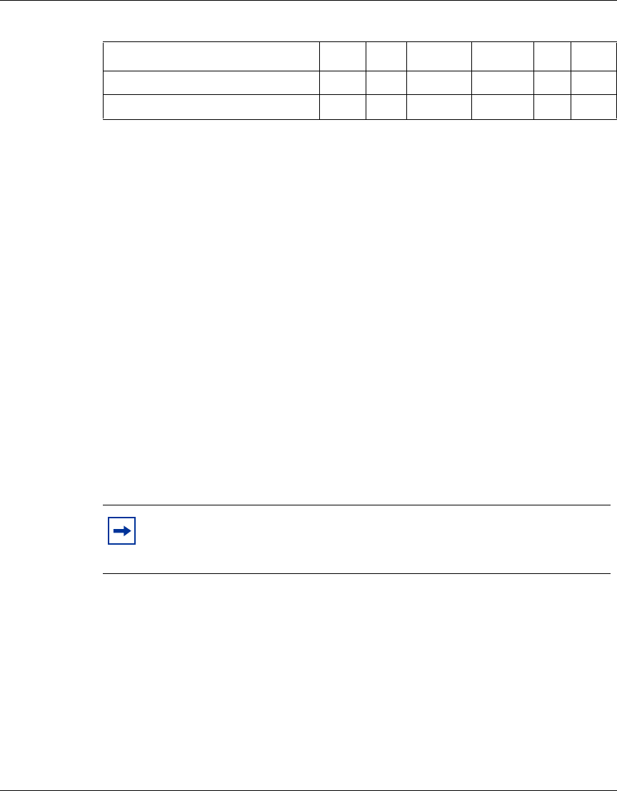
The following table identifies the VPN Router software releases that Nortel
supports and the features and functionality that each software release supports.
The table lists features and functions in alphabetical order.
Table 1 Supported features by release
Feature 6.0 6.05 6.05.140 6.05.170 7.0 8.0
1000BASE-T (1000 GT) Yes Yes Yes Yes Yes Yes
1000BaseSX PCI Yes Yes Yes Yes Yes Yes
1000BaseT PCI Yes Yes Yes Yes Yes Yes
256 Advanced Encryption
Standard (AES) for branch office
tunnels
Ye s Ye s Ye s Ye s Ye s Ye s
2750 hardware platform No No No No Yes Yes
2nd generation Hardware
Accelerator 7811
Ye s Ye s Ye s Ye s Ye s Ye s
4096-bit certificates No No No No No Yes
56/64K Channel Service Unit/
Data Service Unit (CSU/
DSU)-Digital Data System (DDS)
Ye s Ye s Ye s Ye s Ye s Ye s
802.1Q phase 2 Yes Yes Yes Yes Yes Yes
802.1Q VLAN Yes Yes Yes Yes Yes Yes
Ability to configure the Network
Time Protocol (NTP) on an
interface other than LAN 0
No No No No No Yes
Asynchronous branch office
tunnel (ABOT), branch office to
branch office tunnels
Ye s Ye s Ye s Ye s Ye s Ye s
ABOT for 4800 and 9600 Yes Yes Yes Yes Yes Yes
ABOT Layer 2 Tunneling
Protocol (L2TP), Point-to-Point
Tunneling Protocol (PPTP), and
L2TP/IPsec
Ye s Ye s Ye s Ye s Ye s Ye s
Address pools Yes Yes Yes Yes Yes Yes
Asymmetric Digital Subscriber
Line PCI option card
Ye s Ye s Ye s Ye s Ye s Ye s
Advanced routing Yes Yes Yes Yes Yes Yes

Chapter 1 Troubleshooting fundamentals 25
Nortel VPN Router Troubleshooting — Server
Adaptive Server Enterprise
(ASE) encryption
Ye s Ye s Ye s Ye s Ye s Ye s
AES client support Yes Yes Yes Yes Yes Yes
Autobackup interval
configuration
Ye s Ye s Ye s Ye s Ye s Ye s
Automatic backups No No No No Yes Yes
Backup Interface Service Yes Yes Yes Yes Yes Yes
Border Gateway Protocol 4 Yes Yes Yes Yes Yes Yes
Branch office control tunnels Yes Yes Yes Yes Yes Yes
Bulk load Yes Yes Yes Yes Yes Yes
Certificate authority key update Yes Yes Yes Yes Yes Yes
Certificate cross certification No No No No No Yes
Certificate Management Protocol
(CMP)
Ye s Ye s Ye s Ye s Ye s Ye s
Certificate revocation list (CRL)
distribution points
Ye s Ye s Ye s Ye s Ye s Ye s
Circuitless IP Yes Yes Yes Yes Yes Yes
CLI (minimal) Yes Yes Yes Yes Yes Yes
CLI enhancements Yes Yes Yes Yes Yes Yes
Client address redistribution Yes Yes Yes Yes Yes Yes
Client autoconnect Yes Yes Yes Yes Yes Yes
Client medium access control
(MAC) address logging
No No No No No Yes
Client policies Yes Yes Yes Yes Yes Yes
CMP retrieval for certificates No No No No Yes Yes
Cone Network Address
Translation (NAT)
Ye s Ye s Ye s Ye s Ye s Ye s
Configurable Ethernet interface
speed
Ye s Ye s Ye s Ye s Ye s Ye s
Configurable management
security banner
No No No No No Yes
Table 1 Supported features by release (continued)
Feature 6.0 6.05 6.05.140 6.05.170 7.0 8.0

26 Chapter 1 Troubleshooting fundamentals
NN46110-602 02.01
Configurable maximum
transmission unit (MTU)
Ye s Ye s Ye s Ye s Ye s Ye s
Configurable Point-to-Point
Protocol (PPP) TX ring buffer
Ye s Ye s Ye s Ye s Ye s Ye s
Configurable Secure Shell (SSH)
server
No No No No Yes Yes
Configuration warning for
certificate expiration
Ye s Ye s Ye s Ye s Ye s Ye s
Corrected interoperability issue
with Secure Router
No No No No No Yes
CRL update specific time No No No No Yes Yes
Crypto API No No No No Yes Yes
Custom API No No No No Yes Yes
Customizing firewall user
authentication logon
No No No No Yes Yes
Data Link Switching Yes Yes Yes Yes Yes Yes
D e m a n d S e r v i c e s Ye s Ye s Ye s Ye s Ye s Ye s
Domain Name Service (DNS)
enhancements
Ye s Ye s Ye s Ye s Ye s Ye s
Dynamic Host Control Protocol
(DHCP) client public side
Ye s Ye s Ye s Ye s Ye s Ye s
DHCP Relay Yes Yes Yes Yes Yes Yes
D y n a m i c p a s s w o r d Ye s Ye s Ye s Ye s Ye s Ye s
Elliptic curve for user Yes Yes Yes Yes Yes Yes
Enhanced group level user IP
address source and pool name
No No No No No Yes
Entrust client support phase 2 Yes Yes Yes Yes Yes Yes
Equal Cost Multi Path Yes Yes Yes Yes Yes Yes
Encapsulating Security Payload
(ESP) NULL
Ye s Ye s Ye s Ye s Ye s Ye s
Ethernet driver MAC pause flow
control
Ye s Ye s Ye s Ye s Ye s Ye s
Event log enhancements Yes Yes Yes Yes Yes Yes
Table 1 Supported features by release (continued)
Feature 6.0 6.05 6.05.140 6.05.170 7.0 8.0

Chapter 1 Troubleshooting fundamentals 27
Nortel VPN Router Troubleshooting — Server
External Lightweight Directory
Access Protocol (LDAP)
authentication
Ye s Ye s Ye s Ye s Ye s Ye s
External LDAP authentication
phase 2
Ye s Ye s Ye s Ye s Ye s Ye s
External LDAP proxy
enhancement
Ye s Ye s Ye s Ye s Ye s Ye s
Federal Information Processing
Standard (FIPS)
Ye s Ye s Ye s Ye s Ye s Ye s
File backup management No No No No Yes Yes
Filters for management access
using HTTPS and SSH
No No No No No Yes
Firewall enhancements Yes Yes Yes Yes Yes Yes
Firewall Session
Initiation Protocol (SIP)
application level gateway (ALG)
Ye s Ye s Ye s Ye s Ye s Ye s
Firewall User Authentication
(FWUA)
Ye s Ye s Ye s Ye s Ye s Ye s
First generation Hardware
Accelerator
Ye s Ye s Ye s Ye s Ye s Ye s
Fo r c e d l o g o f f Ye s Ye s Ye s Ye s Ye s Ye s
Frame Relay Yes Yes Yes Yes Yes Yes
Frame Relay phase II Yes Yes Yes Yes Yes Yes
Fr a m e d E 1 Ye s Ye s Ye s Ye s Ye s Yes
F R F 1 2 Ye s Ye s Ye s Ye s Ye s Yes
FTP server passive mode No No No No Yes Yes
Fully qualified domain name
registration
Ye s Ye s Ye s Ye s Ye s Ye s
Gratuitous Address Resolution
Protocol (ARP)
Ye s Ye s Ye s Ye s Ye s Ye s
Group 2 Diffie Helman Yes Yes Yes Yes Yes Yes
Group level access control for
certificates
Ye s Ye s Ye s Ye s Ye s Ye s
Table 1 Supported features by release (continued)
Feature 6.0 6.05 6.05.140 6.05.170 7.0 8.0

28 Chapter 1 Troubleshooting fundamentals
NN46110-602 02.01
Group level Remote
Authentication Dial In User
Service (RADIUS) authentication
Ye s Ye s Ye s Ye s Ye s Ye s
Hewlett Packard Open View
discovery of management IP
address
No No No No No Yes
HTTP retrieval of certificate
revocation list
No No No No No Yes
Improved branch office scaling Yes Yes Yes Yes Yes Yes
Improved system software
performance
Ye s Ye s Ye s Ye s Ye s Ye s
Increase the upper bounds of the
forced logoff timer
No No No No No Yes
Integrated Services Digital
Network (ISDN) basic rate
interface (BRI) option for PPP
multilink
No No Yes Yes Yes Yes
ISDN traffic engineering (TE)
processing
No No No No Yes Yes
Interface groups for the Virtual
Router Redundancy Protocol
(VRRP)
Ye s Ye s Ye s Ye s Ye s Ye s
Internet Group Management
Protocol (IGMP) multicast
support for client connections
No No No No No Yes
Internet Security Association and
Key Management Protocol
(ISAKMP) nailed up branch to
branch tunnels
Ye s Ye s Ye s Ye s Ye s Ye s
Inverse split tunneling Yes Yes Yes Yes Yes Yes
IPsec domain name Yes Yes Yes Yes Yes Yes
IPsec subnet mask Yes Yes Yes Yes Yes Yes
LDAP 3DES encryption No No Yes Yes Yes Yes
LDAP optimization scheduling No No No No Yes Yes
LDAP proxy password for AD No No No No Yes Yes
Table 1 Supported features by release (continued)
Feature 6.0 6.05 6.05.140 6.05.170 7.0 8.0

Chapter 1 Troubleshooting fundamentals 29
Nortel VPN Router Troubleshooting — Server
LDAP proxy user authentication Yes Yes Yes Yes Yes Yes
LDAP special characters Yes Yes Yes Yes Yes Yes
LDAP user key encryption No No Yes Yes Yes Yes
License keys Yes Yes Yes Yes Yes Yes
Licensing enhancements Yes Yes Yes Yes Yes Yes
Log message for admin user
password change
No No No No No Yes
Management virtual address Yes Yes Yes Yes Yes Yes
Microsoft Challenge Handshake
Authentication Protocol
(MSCHAP) V2
Ye s Ye s Ye s Ye s Ye s Ye s
M u l t i n e t t i n g Ye s Ye s Ye s Ye s Ye s Ye s
M u l t i p l e b o o t Ye s Ye s Ye s Ye s Ye s Yes
NAT (branch office) Yes Yes Yes Yes Yes Yes
NAT enhancements Yes Yes Yes Yes Yes Yes
NAT Hairpinning Yes Yes Yes Yes Yes Yes
NAT SIP ALG Yes Yes Yes Yes Yes Yes
NAT Traversal Yes Yes Yes Yes Yes Yes
NAT Traversal for branch office
tunnels
No No No No No Yes
NetLock logging Yes Yes Yes Yes Yes Yes
Next-hop traffic filters Yes Yes Yes Yes Yes Yes
NNCLI Phase 1 Yes Yes Yes Yes Yes Yes
NNCLI Phase 2 Yes Yes Yes Yes Yes Yes
N T P Ye s Ye s Ye s Ye s Ye s Ye s
NTP support for Daylight Saving
Time (DST) 2007
No No No No Yes Yes
Online Certificate Status
Protocol (OCSP) server for
certificates
No No No No Yes Yes
OCSP No No No No No Yes
Table 1 Supported features by release (continued)
Feature 6.0 6.05 6.05.140 6.05.170 7.0 8.0

30 Chapter 1 Troubleshooting fundamentals
NN46110-602 02.01
Open Shortest Path First (OSPF) Yes Yes Yes Yes Yes Yes
O S P F v i r t u a l l i n k s Ye s Ye s Ye s Ye s Ye s Yes
Packet Capture (PCAP) Yes Yes Yes Yes Yes Yes
Passgo token authentication No No No No No Yes
PCAP enhancements No No No No Yes Yes
PCAP to disk No No No No Yes Yes
Perfect Forward Secrecy Yes Yes Yes Yes Yes Yes
Ping to validate default route Yes Yes Yes Yes Yes Yes
PPTP and L2TP branch office to
branch office
Ye s Ye s Ye s Ye s Ye s Ye s
Preempt mode in VRRP No No No No Yes Yes
Quality of Service (QoS) Yes Yes Yes Yes Yes Yes
QoS menu enhancements Yes Yes Yes Yes Yes Yes
Quad T1/E1 support Yes Yes Yes Yes Yes Yes
Quality improvements Yes Yes Yes Yes Yes Yes
RADIUS attribute–Filter ID Yes Yes Yes Yes Yes Yes
RADIUS attribute–IP Mask Yes Yes Yes Yes Yes Yes
RADIUS attributes–WINS and
DNS
Ye s Ye s Ye s Ye s Ye s Ye s
RADIUS authentication public
side
Ye s Ye s Ye s Ye s Ye s Ye s
RADIUS dynamic filtering No No No No Yes Yes
RADIUS enhanced access
challenge
Ye s Ye s Ye s Ye s Ye s Ye s
RADIUS interim accounting Yes Yes Yes Yes Yes Yes
RADIUS service Yes Yes Yes Yes Yes Yes
RADIUS timeouts Yes Yes Yes Yes Yes Yes
Respond Internet Control
Message Protocol (ICMP)
packets
No No No No Yes Yes
Respond ICMP packets in VRRP No No No No Yes Yes
Table 1 Supported features by release (continued)
Feature 6.0 6.05 6.05.140 6.05.170 7.0 8.0

Chapter 1 Troubleshooting fundamentals 31
Nortel VPN Router Troubleshooting — Server
Restrict mode Yes Yes Yes Yes Yes Yes
Restricting source IPs access No No No No Yes Yes
Routing Information Protocol
(RIP)
Ye s Ye s Ye s Ye s Ye s Ye s
Route policy enhancements Yes Yes Yes Yes Yes Yes
Routing Table Manager
enhancements for GUI
Ye s Ye s Ye s Ye s Ye s Ye s
Secure FTP (SFTP) server No No No No No Yes
Secure Hash Algorithm-1 Yes Yes Yes Yes Yes Yes
Secure Sockets Layer (SSL)
administration
Ye s Ye s Ye s Ye s Ye s Ye s
SSL VPN integration Yes Yes Yes Yes Yes Yes
Serial interface PPP Yes Yes Yes Yes Yes Yes
Shasta Server Farm Yes Yes Yes Yes Yes Yes
Single V.35 Yes Yes Yes Yes Yes Yes
Simple Network Management
Protocol (SNMP) CSU/DSU
management information base
(MIB)
Ye s Ye s Ye s Ye s Ye s Ye s
SNMP host resource MIB Yes Yes Yes Yes Yes Yes
SNMP interface index No No No No Yes Yes
SNMP support for expired
certificates
Ye s Ye s Ye s Ye s Ye s Ye s
SNMP traps No No No No Yes Yes
SNMP traps and
acknowledgement
Ye s Ye s Ye s Ye s Ye s Ye s
SSH server No No No No Yes Yes
Static IFIndex enhancement No No No No Yes Yes
Static multicast relay Yes Yes Yes Yes Yes Yes
Static tunnel failover for branch
office to branch office
Ye s Ye s Ye s Ye s Ye s Ye s
Table 1 Supported features by release (continued)
Feature 6.0 6.05 6.05.140 6.05.170 7.0 8.0

32 Chapter 1 Troubleshooting fundamentals
NN46110-602 02.01
Support for two hardware
encryption accelerators
Ye s Ye s Ye s Ye s Ye s Ye s
Support for 24 byte LDAP user
encryption
No No No Yes Yes Yes
Syslog Yes Yes Yes Yes Yes Yes
System log lifetime and disk size
limit
No No No No Yes Yes
T1 CSU/DSC Yes Yes Yes Yes Yes Yes
Time and date for LDAP
optimization
No No Yes Yes Yes Yes
Token authentication through
FWUA
Ye s Ye s Ye s Ye s Ye s Ye s
TunnelGuard Yes Yes Yes Yes Yes Yes
TunnelGuard update No No No No No Yes
Two Factor Authentication No No No No No Yes
UNISTEM virtual ALG for firewall No No No No Yes Yes
User control tunnels Yes Yes Yes Yes Yes Yes
User-configurable time for CRL
retrieval
No No Yes Yes Yes Yes
Ve n d o r I D Ye s Ye s Ye s Ye s Ye s Yes
Vendor-specific RADIUS Yes Yes Yes Yes Yes Yes
VeriSign public key infrastructure
(PKI)
Ye s Ye s Ye s Ye s Ye s Ye s
VPN Router 5000E–Restriction
of Hazardous Substances
(RoHS)
No No No No Yes Yes
VPN Router 1700 and 2700 Yes Yes Yes Yes Yes Yes
VPN Router Firewall Yes Yes Yes Yes Yes Yes
VPN Router IPsec Mobility Yes Yes Yes Yes Yes Yes
VPN Router Security Accelerator Yes Yes Yes Yes Yes Yes
VPN Router Stateful FireWall Yes Yes Yes Yes Yes Yes
V R R P Ye s Ye s Ye s Ye s Ye s Ye s
Table 1 Supported features by release (continued)
Feature 6.0 6.05 6.05.140 6.05.170 7.0 8.0
Chapter 1 Troubleshooting fundamentals 33
Nortel VPN Router Troubleshooting — Server
PCAP
The Packet Capture tool (PCAP) is a troubleshooting tool that you use, in
conjunction with other tools such as statistics, logging, network analyzers, and
testers, to remotely troubleshoot the VPN Router and network problems. Use
packet capture to troubleshoot the VPN Router 1010, 1050, and 1100, which are
typically in a small office where no technical expertise is available. You can only
configure PCAP with the command line interface (CLI).
Two options exist when you capture packets:
• No packet loss—This option captures all packets. If the RAM buffer is full, a
forced flush to disk occurs.
• Packet loss—This option skips some packets. If the RAM buffer is full, the
VPN Router drops packets and inserts a malformed packet in the place where
the packets were not captured. The malformed packet stores the number of
dropped packets.
When you capture packets that traverse the VPN Router, you can perform one of
the following actions:
• write them to files in a circular buffer of maximum 999 files
• stop after the number of files reaches the specified maximum
WAN as private interface Yes Yes Yes Yes Yes Yes
Year 2000 compliance Yes Yes Yes Yes Yes Yes
Note: Capturing packets with packet loss does not affect forwarding
performance but capturing packets with no packet loss can affect
performance.
Table 1 Supported features by release (continued)
Feature 6.0 6.05 6.05.140 6.05.170 7.0 8.0

34 Chapter 1 Troubleshooting fundamentals
NN46110-602 02.01
PCAP initially occurs to the RAM buffer. A low priority task writes the RAM
buffer to disk files, called the disk capture files. Although you can configure the
maximum size of this file, PCAP can continue to write the captured data. You
specify the directory where to save the files, and you use the automatic backup
option (specific backup) to copy or move the files to another machine. If you use
the automatic backup option, you must specify the path that specific backup uses
to save PCAP files. If you want to back up a file every time the file changes, select
auto trigger for the specific backup. For more information about automatic
backup, see Nortel VPN Router Administration (NN46110-603).
If you configure the size of a disk capture file to a value other than 0, PCAP
automatically saves the capture in a file and creates a new file with a name as
follows:
<prefix>YYMMDD.<extNr>
where
<prefix> is a two-digit prefix derived from the capture name that identifies the
capture.
YYMMDD is the year, month, and day.
<XXX> is a monotonically incrementing number that is the file extension.
The default value for the buffer size is
• minimum five packets when capturing packets on disk, with no packet loss
• minimum 20 packets when capturing packets on disk, with packet loss
• 1 megabyte (Mbyte) for capturing packets in RAM
PCAP features
The VPN Router uses PCAP to perform the following tasks:
• simultaneously capture network traffic at different sources (physical
interfaces, tunnels, and the VPN Router as a whole)
• capture inbound or outbound traffic, or both

Chapter 1 Troubleshooting fundamentals 35
Nortel VPN Router Troubleshooting — Server
• limit the traffic that the filters capture
• automatically start and stop packet capture with triggers
Security features
Packet capture on the VPN Router provides the following features to enhance
security:
• Packet capture is disabled by default. You can use packet capture using the
CLI through the serial port only.
• To enable packet capture, you must configure a separate capture password.
• When you save a capture buffer to a file on disk, the router encrypts the file.
You must provide the capture password to decrypt PCAP files.
• To open a capture file, the VPN Router ships with a tool called openpcap. The
tool works for both 128-bit and 56-bit versions and uses the same
cryptographic library that the server code uses. The openpcap tool prompts
you for a password.
• The router does not save packet capture configuration in LDAP or in the
configuration file. After you restart the VPN Router, you lose the packet
capture configuration.
File format
The router stores packets in PCAP/TCPDUMP file format. Many tools recognize
this file format. The router saves packets with the following additional
information:
• timestamp of the packet
• length of the portion of the packet present in the PCAP file
• length of the entire packet as the router received it or sent it on the wire
Note: The VPN Router does not provide tools to open and view
captured data. You must offload the PCAP files to view them.

36 Chapter 1 Troubleshooting fundamentals
NN46110-602 02.01
Capture types
The VPN Router captures packets from the following sources:
• physical interfaces, including the following
— Asynchronous digital subscriber line (ADSL) or asynchronous transfer
mode (ATM)
— Fast Ethernet and Gigabit Ethernet, including traffic not directed to the
VPN Router (promiscuous mode)
— Dial (V.90 and asynchronous Point-to-Point Protocol [PPP])
— Integrated services digital network basic-rate interface (ISDN BRI)
—serial
• tunnels
— branch offices (all types)
—user tunnels
• all IP traffic on the VPN Router
The following sections describe each type of capture.
Physical interface captures
Packet capture of traffic on a physical interface can help you troubleshoot
Layer 2 issues, connectivity issues, and performance issues. The router saves the
Layer 2 header in the PCAP file for each packet. You can convert PCAP files
containing traffic captured on a physical interface to most file formats, including
Network General Sniffer.
Tunnel captures
You can use packet capture of traffic over tunnels to help troubleshoot a specific
tunnel problem. For example, you can create a tunnel capture object to diagnose
the following types of problems:
• a protocol not working for a particular user
• performance issues for a particular user
• OSPF not working properly inside a specific branch office tunnel

Chapter 1 Troubleshooting fundamentals 37
Nortel VPN Router Troubleshooting — Server
The router encapsulates tunnel captures saved to disk with raw IP encapsulation.
When you convert these files to file formats that do not support raw IP
encapsulation (including Sniffer), you need Layer 2 encapsulation.
You can configure a capture object for an existing tunnel or for uninitiated tunnels.
You can also use persistent mode for tunnel capture objects. If you use persistent
mode and a captured tunnel disconnects, packet capture restarts automatically
after another tunnel session that matches the capture criteria begins. Tunnel
capture criteria include the following:
• tunnel type: user tunnel, branch office, ABOT initiator, or ABOT responder
• tunnel protocol: IPsec, L2TP, PPTP, or Layer 2 Forwarding (L2F)
• IP address of the remote peer on the tunnel session
• user ID (or another criterion to specify the user)
If you start a tunnel capture object and more than one tunnel matches the capture
criteria, the capture object captures only the first tunnel. If no tunnel matches the
criteria, packet capture waits for a tunnel that matches the criteria. If you
configure more than one capture object with the same criteria, the first matching
tunnel uses the first PCAP object, and the next matching tunnel uses the other
capture object. This way you can capture a set of tunnels with the same criteria in
different capture files.
For performance reasons, only one capture object runs at a time for a specific
tunnel. Multiple tunnel capture objects can run at the same time, but each object
must capture a different tunnel.
Global IP captures
Global (raw) IP packet capture captures all IP traffic traversing a physical
interface or tunnel on the VPN Router. Only one global IP capture object can run
at one time. The router captures packets as they are encapsulated or decapsulated
(depending on the capture direction that you configure). To restrict the amount of
traffic that a global IP can capture, see “Filters and triggers” on page 38.
38 Chapter 1 Troubleshooting fundamentals
NN46110-602 02.01
A global IP capture object captures packets starting from the IP header; the
capture object does not save Layer 2 header information in the capture file.
Because the router captures both encrypted and decrypted packets, global IP
packet capture is useful in troubleshooting VPN issues.
Filters and triggers
You can apply existing interface filters to a capture object as a capture filter or as a
start or stop trigger. You configure capture filters, start triggers, and stop triggers
independently.
Capture filters
To troubleshoot a specific type of problem and to limit the amount of data stored
in the capture buffer, you can configure a predefined interface filter so that non-IP
frames do not match a filter. For example, if you configure a capture object with a
filter for a serial interface configured with PPP, no Link Control Protocol (LCP)
traffic matches filter criteria on a capture object. You can configure the capture
object to always capture non-IP frames or to always discard them.
To apply a filter to a capture object, you must first stop the capture object.
Triggers
By default, the system saves frames to the capture buffer as soon as a capture
object starts. You can configure predefined or user-defined interface filters as
triggers for capture objects. A trigger causes a capture object to start or stop
automatically after it receives certain packets.
• A start trigger causes the system to wait for a specific packet before it starts
saving packets to the capture buffer.
Note: If capture objects for physical interfaces or tunnels run at the
same time as a global IP capture object, this action affects performance
on the VPN Router.
Note: You cannot configure filters and triggers on ADSL and ATM
interfaces.

Chapter 1 Troubleshooting fundamentals 39
Nortel VPN Router Troubleshooting — Server
• A stop trigger causes the system to stop saving traffic in the capture buffer
after the system encounters a specific packet that matches the stop trigger. The
packet capture object, however, does not fully stop. A start trigger can still
restart the capture.
A trigger works only for the direction for which you configure the capture. For
example, if you enable packet capture for outgoing traffic only, and the type of
packet that triggers the capture to start or stop arrives only in incoming packets,
the trigger does not work.
You can use triggers with filters. Like filters, triggers never match non-IP frames.
The router captures the packets that triggered the capture object to start or stop if
they match capture filters.
You can use a start trigger with a stop trigger to capture specific transaction-
oriented traffic. If you configure both a start and a stop trigger, the start trigger can
reenable saving traffic to a capture buffer. You can activate both a start trigger and
a stop trigger on the same packet. In this case, only one packet is captured.
Memory considerations
The number of packet capture objects allocated on a VPN Router depends on the
available contiguous memory. When you create a capture object, you can specify
the capture buffer size (the default buffer size is 1 MB).
You can create new capture objects until the maximum block size reaches 25 MB.
(The VPN Router does not allow you to reduce the maximum block size to less
than 25 MB.) If you allocate too much memory to packet capture buffers, you
receive an error message suggesting a smaller buffer size.
To check the maximum block size, choose Status, Statistics, and then click
Memory in the Resources section. Scroll to the bottom of the window to find the
maximum block size. The output looks similar to the following
Shared Heap Statistics:
status bytes blocks ave block max block
------ --------- -------- ---------- ----------
current
free 40542960 18 2252386 39532912
alloc 64815872 135 480117 -

40 Chapter 1 Troubleshooting fundamentals
NN46110-602 02.01
You can display the same information by entering the command show status
statistics resources memory.
Performance considerations
Running packet capture can affect VPN Router performance. You can run only
one capture object at a time for a specific source (interface or tunnel). Multiple
capture objects can exist for the same source, but only one object can start. You
can run capture objects for different sources at the same time with no limitations.
To reduce the effect on VPN Router performance, use packet capture for
troubleshooting only and observe the following guidelines:
• Configure the capture object to capture the least amount of data needed for
troubleshooting: for example, only inbound or outbound traffic, only the first
n bytes of the packet.
• Configure a capture object for promiscuous mode only when necessary.
(Promiscuous mode affects VPN Router performance.)
• Configure filters and triggers to capture only relevant traffic, in particular if
you need to run the global IP object.
• Delete a capture object or capture files when you no longer need them to free
up memory or disk space.
• Do not run capture objects for physical interfaces or tunnels at the same time
that you run the global IP capture object (the router captures some packets
more than once).
Hardware LEDs
This section describes the meaning of Light Emitting Diodes (LED) on Nortel
VPN Router products and associated optional interface cards. For more
information about alerts and alarms, see “Status and logging” on page 81. For
more information about each hardware platform, see the installation document for
the specific platform.

Chapter 1 Troubleshooting fundamentals 41
Nortel VPN Router Troubleshooting — Server
The following table identifies the LEDs on a VPN Router 600.
If the Boot LED and the Ready LED light at the same time, the Nortel VPN
Router 600 is in recovery mode.
The following table identifies the LEDs on a VPN Router 1010, 1050, or 1100.
Table 2 Nortel VPN Router 600 LEDs
LED Condition Indicates
Power On The gateway receives DC power.
Power Off The gateway does not receive DC
power.
Alert Red A serious alarm condition exists that
requires attention.
Attention Amber A nonfatal alarm condition exists.
Ready Green The gateway starts and is operational.
Boot Amber The gateway is starting and is in a
nonready state.
Table 3 Nortel VPN Router 1000 Series LEDs
LED Condition Indicates
Boot/Ready Yellow The gateway is booting and is in a
nonready state.
Green The restart process is complete and
the gateway is in a state of readiness.
Alert Yellow An alarm condition exists. The alarm
can indicate a serious condition, such
as a hardware defect or a software
attention condition.
Off No alarm condition exists.

42 Chapter 1 Troubleshooting fundamentals
NN46110-602 02.01
The following table identifies the LEDs on a VPN Router 1600.
The following table identifies the LEDs on a VPN Router 1700, 1740, and 1750.
Table 4 Nortel VPN Router 1600 LEDs
LED Condition Indicates
Nortel logo Blue The power is on.
Off The power is off.
Alert/Fail Yellow A nonfatal status requires attention.
Red A hardware error exists, which also
causes the beeping condition.
Boot/Ready Yellow The system boot is in process or a
nonready state.
Green The system is in a state of readiness.
Table 5 Nortel VPN Router 1700 Series LEDs
LED Condition Indicates
Nortel logo On The gateway receives AC power.
Off The gateway does not receive AC
power.
Alert Yellow A nonfatal alarm condition exists.
Red A serious alarm condition exists that
requires attention.
Boot/Ready Yellow The gateway is booting and is in a
nonready state.
Green The boot process is complete and the
gateway is in a state of readiness.

Chapter 1 Troubleshooting fundamentals 43
Nortel VPN Router Troubleshooting — Server
The following table identifies the LEDs on a VPN Router 2600.
The following table identifies the LEDs on a VPN Router 2700.
Table 6 Nortel VPN Router 2600 LEDs
LED Condition Indicates
Nortel logo On The gateway receives AC power.
Off The gateway does not receive AC
power.
Alert Yellow A nonfatal alarm condition exists.
Red A hardware error exists, which causes
the beeping condition.
Boot/Ready Yellow The gateway is booting and is in a
nonready state.
Green The boot process is complete and the
gateway is in a state of readiness.
Table 7 Nortel VPN Router 2700 LEDs
LED Condition Indicates
Nortel logo On The gateway receives AC power.
Off The gateway does not receive AC
power.
Alert/Fail Yellow A nonfatal alarm condition exists.
Red A serious alarm condition exists that
requires attention.
Boot/Ready Yellow The gateway is booting and is in a
nonready state.
Green The boot process is complete and the
gateway is in a state of readiness.

44 Chapter 1 Troubleshooting fundamentals
NN46110-602 02.01
The following table identifies the LEDs on a VPN Router 2750.
The following table identifies the LEDs on a VPN Router 4600.
Table 8 Nortel VPN Router 2750 LEDs
LED Condition Indicates
Nortel logo On The gateway receives AC power.
Off The gateway does not receive AC
power.
Alert Yellow A nonfatal alarm condition exists.
Red A serious alarm condition exists that
requires attention.
Boot/Ready Yellow The gateway is booting and is in a
nonready state.
Green The boot process is complete and the
gateway is in a state of readiness.
Table 9 Nortel VPN Router 4600 LEDs
LED Condition Indicates
Alert/Fail Yellow A nonfatal alarm condition exists.
Red A serious alarm condition exists that
requires attention.
Boot/Ready Yellow The gateway is booting and is in a
nonready state.
Green The boot process is complete and the
gateway is in a state of readiness.
Power Green The gateway receives AC power.
Flashing A hardware failure exists. Contact
Global Nortel Technical Support.
Hard Disk Green The LED becomes a U for unlocked
after the hard drive is unlocked by
using the hard drive key. When locked
the LED indicates the hard drive
number, 0 or 1.
Flashing The switch reads or writes to the disk.

Chapter 1 Troubleshooting fundamentals 45
Nortel VPN Router Troubleshooting — Server
The following table indicates the LEDs on the VPN Router 5000 and 5000E.
LAN Port Green (right) The LAN port operates at 100 Mb/s.
Off (right) The LAN port operates at 10 Mb/s.
Flashing
(right)
The switch transmits or receives data.
Orange (left) The cable connections between the
LAN port and the hub are good.
Off (left) The cable connections between the
LAN port and the hub are faulty.
Table 10 Nortel VPN Router 5000 LEDs
LED Condition Indicates
Alert Yellow A nonfatal alarm condition exists.
Fail Red A serious alarm condition exists that
requires attention.
Boot Yellow The gateway is booting and is in a
nonready state.
Ready Green The boot process is complete and the
gateway is in a state of readiness.
Power supply Steady green This power supply and the system
receive power.
Flashing
green
This power supply receives power,
but the system is not turned on.
Yellow The power cord is not plugged into
this power supply or the power supply
failed and you need to replace it.
1000BASE-T Ethernet
port Activity Link
Steady green The port connects to a valid link
partner.
Flashing
green
The LAN port sends or receives
network data.
Off The port does not link to a valid
partner.
Table 9 Nortel VPN Router 4600 LEDs
LED Condition Indicates

46 Chapter 1 Troubleshooting fundamentals
NN46110-602 02.01
The following table identifies the LEDs on optional cards for the Nortel VPN
Router.
1000BASE-T Ethernet
port 10/100/1000
Orange The LAN port operates at 1000 Mb/s.
Green The LAN port operates at 100 Mb/s.
Off The LAN port operates at 10 Mb/s.
10/100BASE Ethernet
port Activity Link
On The cable connections between the
LAN port and the hub are good.
Flashing The LAN port sends or receives
network data.
Off The cable connections between the
LAN port and the hub are faulty.
10/100BASE Ethernet
port 10/100
On The LAN port operates at 100 Mb/s.
Off The LAN port operates at 10 Mb/s.
Table 11 Option card LEDs
Card LED Condition Indicates
10/100BASE ACT/LINK Steady or
flashing
green
The card sends or receives
network data. The frequency
of the flashes increases with
increased traffic.
Off The card does not send or
receive data.
10/100TX Green The port operates at 100 Mb/
s.
Off The port operates at 10 Mb/s.
Table 10 Nortel VPN Router 5000 LEDs (continued)
LED Condition Indicates

Chapter 1 Troubleshooting fundamentals 47
Nortel VPN Router Troubleshooting — Server
1000BASE-T
(1000GT)
ACT/LNK Steady green The port connects to a valid
link partner.
Flashing
green
The LAN port sends or
receives network data.
Off The port does not link to a
valid partner.
10/100/1000 Off The LAN port operates at
10 Mb/s.
Green The LAN port operates at
100 Mb/s.
Orange The LAN port operates at
1000 Mb/s.
1000BASE-SX ACT/LNK Steady green The port connects to a valid
link partner.
Flashing
green
The LAN port sends or
receives network data.
Off The port does not link to a
valid partner.
ADSL WAN Tx/Rx and
CONN
Steady green The ADSL interface card is
not initialized; the software
driver is not installed.
Off The ADSL interface card
initializes, but does not
establish a link with the ADSL
network.
Flashing
green and off
The ADSL interface card
attempts to establish a link
with the ADSL network.
Steady green
and off
The ADSL interface card
establishes a link with the
ADSL network.
Steady green
and flashing
green
The ADSL interface card
sends or receives network
data. (The LED can appear
dim.)
Table 11 Option card LEDs (continued)
Card LED Condition Indicates

48 Chapter 1 Troubleshooting fundamentals
NN46110-602 02.01
T1/E1 CSU/
DSU WAN
LED 1 (top left) Red A loss-of-signal or
out-of-frame condition is
detected on the receive
signal.
LED 2 (top
right)
Blue An upstream failure is
received denoted by an alarm
indication signal.
LED 3 (bottom
left)
Yellow The far-end equipment is in
the red alarm condition.
LED 4 (bottom
right)
Green Normal operation.
Quad T1/E1
CSU/DSU
WAN
LED 1 (top left) Off Port 1 is disabled.
On Port 1 is enabled and
operates normally.
Flashing Port 1 is enabled and in an
alarm state (red, yellow, or
blue).
LED 2 (top
right)
Off Port 2 is disabled.
On Port 2 is enabled and
operates normally.
Flashing Port 2 is enabled and in an
alarm state (red, yellow, or
blue).
LED 3 (bottom
left)
Off Port 3 is disabled.
On Port 3 is enabled and
operates normally.
Flashing Port 3 is enabled and in an
alarm state (red, yellow, or
blue).
LED 4 (bottom
right)
Off Port 4 is disabled.
On Port 4 is enabled and
operates normally.
Flashing Port 4 is enabled and in an
alarm state (red, yellow, or
blue).
Table 11 Option card LEDs (continued)
Card LED Condition Indicates

Chapter 1 Troubleshooting fundamentals 49
Nortel VPN Router Troubleshooting — Server
V.35/X.21 WAN LED 1 (top left) Red No external transmit clock
source is available.
LED 2 (top
right)
Green The signals CDC and DSR
are on between the DSU and
the adapter. LED 2 detects
receive link status.
LED 3 (bottom
left)
Green Power to the adapter is on
and the onboard microcode is
loaded.
LED 4 (bottom
right)
Green The cable is detected.
SSL VPN
Module 1000
Online Steady green Indicates the SSL VPN
Module 1000 operates
normally.
Yellow Indicates a reset on the
module.
Off Indicates the module does
not receive power.
Activity LED1 Steady green Indicates the module
operates normally.
Flashing
green
Indicated activity occurs.
Yellow Indicates a reset on the
module.
Activity LED2 This LED is often lit, but it has
no meaning.
Utilization One LED
steady green
CPU utilization is
approximately 25 percent.
Two LEDs
steady green
CPU utilization is
approximately 50 percent.
Three LEDs
steady green
CPU utilization is
approximately 75 percent.
Four LEDs
steady green
CPU utilization is
approximately 100 percent.
Flashing in
unison
The SSL VPN 1000 Module
is idle.
Table 11 Option card LEDs (continued)
Card LED Condition Indicates

50 Chapter 1 Troubleshooting fundamentals
NN46110-602 02.01

51
Nortel VPN Router Troubleshooting — Server
Chapter 2
Troubleshooting tools
The VPN Router supports standard IP tools such as ping, Traceroute, and Address
Resolution Protocol (ARP) show and delete. You access these tools through the
Admin, Tools window. You can also use special tools beyond the standard tools
available. These special tools include client- and VPN Router-based tools.
For more information, see the following sections:
•“Standard tools” on page 51
•“Client-based tools” on page 57
•“System-based tools” on page 57
•“Other tools” on page 79
•“System configuration” on page 79
•“File management” on page 79
Standard tools
Ping
The ping command generates an Internet Control Message Protocol (ICMP)
echo-request message, which a host can send to test node reachability across a
network. The ICMP echo-reply message indicates that the message reached the
node. To use ping, enter the following command in User EXEC mode:
ping <IP address> <1–999> [data-size <1–4048>] [source
address|source hostname]
The following list explains the command parameters:

52 Chapter 2 Troubleshooting tools
NN46110-602 02.01
• IP address—the address to ping
• 1–999—(Optional) the number of echo requests to return
• 1–4048—(Optional) the size of the ping request packet
• source address|source hostname—(Optional) the source address or hostname
of the outgoing ping request
To use ping from the GUI
1Choose Admin, Tools.
The System Tools window appears.
2Provide the necessary details in the Ping section.
3Click Ping.
Traceroute
The traceroute tool measures a network round-trip delay. The tool sends messages
for each hop and the wait occurs between each message. If the address is
unreachable, the tool uses the following formula to determine how long it takes
for the traceroute command to time out.
maximum hops (30) x the wait timeout (5) x 3 seconds
To use traceroute, enter the following command in User EXEC mode:
trace ip <IP address> [source <IP address>] [hops <0-60>]
[wait <0–60>]
The following list explains the command parameters:
• source <IP address>—IP address of the outgoing trace packet
• hops—maximum number of hops to traverse
• wait—the wait, in seconds, for a response
To use traceroute from the GUI
1Choose Admin, Tools.
The System Tools window appears.

Chapter 2 Troubleshooting tools 53
Nortel VPN Router Troubleshooting — Server
2Provide the necessary details in the Trace Route section.
3Click Traceroute.
mtrace
The multicast traceroute (mtrace) tool is a multicast diagnostic tool that uses
special Internet Group Management Protocol (IGMP) packets with a different
type code than normal IGMP packets. The mtrace tool requires the Advanced
Routing license.
To use mtrace, the network topology must be a standard IGMP-based tree of
routers. All interfaces in the tree must be IGMP-enabled.
For more information, see Figure 1 “IGMP-based tree” on page 54, where S is the
source, Q is the mtrace querier and destination, and G is the host that subscribes to
group G.
54 Chapter 2 Troubleshooting tools
NN46110-602 02.01
Figure 1 IGMP-based tree
Table 2 “Non-mtrace compliant network” on page 55 shows a network topology
where the mtrace response does not contain the full trace between the destination
and source. The request message goes to both the upstream interface of one router
and the IGMP downstream Querier interface of another router. The first router
responds with the code RPF_IF (Traceroute request arrived on the expected RPF
interface for this source, group).
`
G
`
S
Q
Chapter 2 Troubleshooting tools 55
Nortel VPN Router Troubleshooting — Server
Figure 2 Non-mtrace compliant network
To use mtrace, enter the following command in User EXEC mode:
mtrace [source] [destination] [group] [response
<response-address>| max-hops <max-hops> | response-ttl
<resp-ttl> | verbose | response-time <response- time>]
The following list explains the command parameters:
• source—unicast IP address of the source of the traceroute
• destination—(Optional) unicast address of the destination
The default is the system on which you enter the command.
• group—(Optional) multicast group address to trace
The default group is MBONE AUDIO—224.2.0.1.
• response-address—(Optional) unicast or multicast address where the response
is sent
The default is the system on which you enter the command.
• max-hops—(Optional) maximum number of hops to traverse
Q (D)
IGMP Querier
`
S
Upstream
Request

56 Chapter 2 Troubleshooting tools
NN46110-602 02.01
The default number of maximum hops is 32.
• resp-ttl—(Optional) time-to-live (TTL) to use for the multicast response on
the response packet
The default response TTL is 64.
• verbose—(Optional) show additional statistics like the route that forwarded
the initial trace
• response-time—(Optional) the time to wait for a trace response
The default response time is 3 seconds.
To use mtrace from the GUI
1Choose Admin, Tools.
The System Tools window appears.
2Provide the necessary details in the Multicast Trace Route section.
3Click MTrace.
ARP
The ARP dynamically discovers the low-level physical network hardware address
that corresponds to the high-level IP address for a host. Use ARP on physical
network systems that support broadcast packets heard by all hosts on the network.
To delete ARP table entries, enter the following command in the Global
Configuration mode:
arp <IP address> [word]
Word represents the optional 48-bit hardware address of the ARP entry.
To delete ARP table entries from the GUI
1Choose Admin, Tools.
The System Tools window appears.
2Type the target address.

Chapter 2 Troubleshooting tools 57
Nortel VPN Router Troubleshooting — Server
3Click ARP Delete.
Client-based tools
IPsec VPN Client Monitor provides network statistics on device, connection, and
network errors that help monitor traffic flow and assess IPsec connection
performance. Statistic counters update once a second. For more information about
the IPsec VPN Client Monitor, see the Nortel VPN Client online Help.
Microsoft Point-to-Point Tunneling Protocol (PPTP) Dial-Up Networking
Monitor provides network statistics on device, connection, and network protocols
that help monitor traffic flow and assess PPTP connection performance. For more
information about the PPTP Dial-Up Networking Monitor, see the PPTP help or
the Microsoft PPTP client documentation.
System-based tools
Use the Status, Health Check menu path to view colored status indicators that
evaluate individual component status, and click associated hyperlinks to go
directly to manager windows for corrective action.
Use the Status, Statistics menu path to view detailed system and network
statistics.
Use the Status, Security, Config Log, System Log, and Event Log menu paths to
view various log recording systems and network events that help you trace
problems and determine their origins.
Configuring core dump retrieval on diskless routers
The VPN Routers 1010, 1050, and 1100 use a compact flash disk, instead of a
traditional hard disk, which provides 64 MB of flash disk storage. Because of the
limited storage capacity, core dump files do not save on the router and, therefore,
you must upload the generated core dump file to a File Transfer Protocol (FTP)
server for later troubleshooting.

58 Chapter 2 Troubleshooting tools
NN46110-602 02.01
1Choose Admin, Administrator.
The Administrator window appears.
2In the FTP Coredump section, select Enabled.
3In the Host box, type the FTP server IP address.
4In the Path box, type the directory path where you want to save the core dump
file. If you leave this box blank, the file saves in the root directory.
5In the UserID box, type the FTP user logon name.
6In the Password box, type the FTP user password.
7Confirm the user password.
8Click OK.
In the command line interface (CLI), use the ftp-coredump command. For more
information about this command, see Nortel VPN Router Using the Command
Line Interface (NN46110-507).
Enabling packet capture on a VPN Router
You must use a serial connection to capture packets. You cannot enable packet
capture through a Telnet session.
To prepare to run packet capture on the VPN Router
1If necessary, start the VPN Router with a software version that includes the
PCAP feature.
2Turn on the terminal or PC.
3Configure the terminal or PC as follows:
• 9600 baud
• 8 data bits
• 1 stop bit
• No parity
• No flow control
4Connect the serial cable (supplied with the VPN Router) from the VPN
Router serial port to the terminal or to the communications port on the PC.

Chapter 2 Troubleshooting tools 59
Nortel VPN Router Troubleshooting — Server
5On the PC, start HyperTerminal or another terminal emulation program, and
then press Enter.
The Welcome window appears.
Welcome to the VPN Router
Copyright (c) 2007 Nortel Networks Ltd.
Version: V04_90.185
Creation date: May 27, 2004, 20:51:06
Date: 05/27/2004
Unit Serial Number:317563
Please enter the administrator's user name:
6Enter the administrator user name and password.
Please enter the administrator's user name: admin
Please enter the administrator's password: *****
The serial main menu appears.
Main Menu: System is currently in NORMAL mode.
1) Interfaces
2) Administrator
3) Default Private Route Menu
4) Default Public Route Menu
5) Create A User Control Tunnel(IPsec) Profile
6) Restricted Management Mode FALSE
7) Allow HTTP Management TRUE
8) Firewall Options
9) Shutdown
B) System Boot Options
P) Configure Serial Port
C) Controlled Crash
L) Command Line Interface
R) Reset System to Factory Defaults
E) Exit, Save and Invoke Changes
Please select a menu choice (1 - 9,B,P,C,L,R,E): L
7Access the command line interface by typing the letter L (uppercase or
lowercase) at the prompt.

60 Chapter 2 Troubleshooting tools
NN46110-602 02.01
The User EXEC prompt appears:
CES>
8Enter Privileged EXEC mode.
CES>enable
Password:*****
9Enable packet capture globally on the VPN Router and create the capture
password. Use this password to open capture files with the openpcap utility.
Use at least eight characters for the capture password and include at least one
number.
CES#capture enable
Please specify password for encrypting capture files.
Password: ********
Reenter password: ********
10 Optionally, you can now change the VPN Router administrator password.
CES#configure terminal
Enter configuration commands, one per line. End with
Ctrl/z.
CES(config)#adminname <admin_name> password <new_password>
CES(config)#exit
CES#
After you enable packet capture, it remains enabled until you explicitly disable it
with the no capture enable command or until you reboot the VPN Router. You
can now configure and start packet capture objects.
Saving captured data
By default, packet capture stops copying data to the capture buffer after the buffer
becomes full. To configure a capture object to overwrite the data in the buffer with
new data, run the wrapping command.
Use the command capture save to save captured network traffic from the
capture buffer in memory to a file on the VPN Router disk. You must stop packet
capture before you can save the buffer to a file. For more information, see
“Starting, stopping, and saving capture objects” on page 67.

Chapter 2 Troubleshooting tools 61
Nortel VPN Router Troubleshooting — Server
Capturing packets to disk file
To configure PCAP, you must first enter CLI Capture Configuration mode. For
more information about CLI Capture Configuration mode, see Nortel VPN Router
Using the Command Line Interface (NN46110-507).
Five CLI commands exist to capture packets to disk file. These commands are
•filepath—sets the PCAP file path
•buffersize—sets the size of the RAM buffer
•filesize—sets the size of a disk capture file
•maxfiles—sets the maximum number of disk capture files
•capture-all—sets PCAP capture mode to either loss or no loss
The following sections describe each of these commands.
Setting the PCAP file path
To configure the file path to save PCAP files, from CLI Capture Configuration
mode, enter the following command:
filepath <path>
where path specifies the location to which to save the PCAP files.
For example, enter
CES(capture-ethernet)#filepath /ideX/system/log
Setting the size of the RAM buffer
To configure the RAM buffer size, from CLI Capture Configuration mode enter
the following command:
buffersize <size>
Note: To back up later using the autobackup functionality, the specified
file path for the PCAP files must be a directory under /ideX/system.

62 Chapter 2 Troubleshooting tools
NN46110-602 02.01
where size is the size of the RAM buffer.
For example, enter
CES(capture-ethernet)#buffersize 1048576
Setting the size of a disk capture file
To configure the size of the disk capture file, from CLI Capture Configuration
mode enter the following command:
filesize <max_size>
where max_size is the size of the capture file.
For example, enter
CES(capture-ethernet)#filesize 10485760
Setting the maximum number of disk capture files
To configure the maximum number of disk capture files, from CLI Capture
Configuration mode enter the following command:
maxfiles <max_files>
where max_files is the maximum number of files to save to disk for this capture
For example, enter
CES(capture-ethernet)#maxfiles 99
Saving captured data
To configure the PCAP capture mode to loss or no loss, from CLI Capture
Configuration mode enter the following command:
capture-all

Chapter 2 Troubleshooting tools 63
Nortel VPN Router Troubleshooting — Server
or
No capture-all
For example, enter
CES(capture-ethernet)#capture-all
Configure and run packet capture objects
This section provides instructions to create, configure, start, and stop capture
objects, as well as instructions to save captured traffic to a file on disk. For more
information about the complete syntax of the packet capture commands shown in
this section, see the Nortel VPN Router Using the Command Line Interface
(NN46110-507).
Creating a capture object
To create a capture object, use the capture add command. For more information
about the types of object that you can create, see “Capture types” on page 36.
1To view the types of capture objects that you can configure, enter the
following command at the Privileged EXEC prompt.
CES# capture add <object_name> ?
For example, enter the following command:
CES# capture add test1 ?
atm ATM interface capture
bri Bri interface capture
dial Dial interface capture
FastEthernet Fast Ethernet interface capture
GigabitEthernet Gigabit Ethernet interface capture
global Global RAW IP capture
serial Serial interface capture
tunnel Tunnel capture
2Create a capture object by specifying an object name and type.

64 Chapter 2 Troubleshooting tools
NN46110-602 02.01
In the following example, you create a capture object called test_ethernet1
that captures traffic on Ethernet interface 1/2.
CES# capture add test_ethernet1 FastEthernet 1/2
CES#
In the following example, you create a capture object called test_tunnel that
captures tunnel traffic.
CES# capture add test_tunnel tunnel
CES#
Configuring a capture object
After you create a capture object, you can configure it to capture a subset of the
traffic that travels over the physical interface, tunnel, or the VPN Router as a
whole. You can configure a capture object to do the following:
• capture inbound or outbound traffic or both
• capture a nondefault number of octets from each packet
• apply an interface filter to the object
• configure start and stop triggers for the object
• specify whether the capture stops after the buffer is full or whether new data
overwrites the existing data
To configure a capture object
1Browse to Capture Configuration mode by entering the capture command
with the object name.
CES#capture ether0
CES(capture-ethernet)#
The resulting prompt shows the type of capture object (physical interface,
tunnel, or global IP).
Chapter 2 Troubleshooting tools 65
Nortel VPN Router Troubleshooting — Server
2Display all parameters that you can configure for that type of capture object.
CES(capture-ethernet)#?
Packet capture mode
direction Captures in one direction
exit Exits capture mode
filter Applies interface traffic filter to
capture only matching traffic
length Specifies how many octets to capture for
every packet
no Disables features and settings
promiscuous Enables promiscuous mode when capture is
running
trigger Enables triggers
wrapping Continues capturing when buffer gets full
CES(capture-ethernet)#
3Edit one or more parameters as required.
For more information about command syntax, see Nortel VPN Router Using the
Command Line Interface (NN46110-507).
Note: The promiscuous parameter is available for Ethernet capture
objects only.

66 Chapter 2 Troubleshooting tools
NN46110-602 02.01
Tunnel capture parameters
Capture objects for tunnels use several unique parameters. The following example
creates a tunnel object called bot1, navigates to Capture Configuration mode, and
displays the commands for tunnel objects. The bold commands are available only
for tunnel objects. For more information about tunnel capture objects, see “Tunnel
captures” on page 36.
CES#capture add bot1 tunnel
CES#capture bot1
CES(capture-tunnel)#?
Packet capture mode
direction Captures in one direction
exit Exits capture mode
filter Applies interface traffic filter to capture
only matching traffic
length Specifies how many octets to capture for
every packet
no Disables features and settings
persistent Restarts capture on session disconnect
remoteip Captures sessions from this IP address
trigger Enables triggers
type Captures only sessions of specific type
userid Captures sessions from this user
wrapping Continues capturing when buffer gets full
CES(capture-tunnel)#
For more information about command syntax, see Nortel VPN Router Using the
Command Line Interface (NN46110-507).

Chapter 2 Troubleshooting tools 67
Nortel VPN Router Troubleshooting — Server
Global IP parameters
The configurable parameters for the global IP capture object are the same as the
parameters available for physical interface objects. The following example creates
a global capture object called rawip, navigates to Capture Configuration mode,
and displays the commands for the global capture object. For more information
about global IP capture objects, see “Global IP captures” on page 37.
CES#capture add rawip global
CES#capture rawip
CES(capture-global)#?
Packet capture mode
direction Captures in one direction
exit Exits capture mode
filter Applies interface traffic filter to
capture only matching traffic
length Specifies how many octets to capture for
every packet
no Disables features and settings
trigger Enables triggers
wrapping Continues capturing when buffer gets full
CES(capture-global)#
Starting, stopping, and saving capture objects
The following example shows how to start a capture object called test_ether1,
stop it, save the buffer to a file (called test_ether1.cap), and finally, clear the
capture buffer. You must run all commands in Privileged EXEC mode.
CES#capture test_ether1 start
CES#capture test_ether1 stop
CES#capture test_ether1 save test_ether1.cap
Saving capture test_ether1 to file /ide0/test_ether1.cap
please wait . . .
220 frames written successfully
CES#clear capture test_ether1
CES#
Displaying capture status
Use the show capture command to display a list of capture objects and to display
the configuration and status of a specific capture object.

68 Chapter 2 Troubleshooting tools
NN46110-602 02.01
In the following example, the show capture command is run with no object
name to display a list of all the capture objects configured on the VPN Router.
CES# show capture
Name Type Size Buffer use Count
State
bot1 TUNNEL 1048576 0% 0
EMPTY
ether0 ETHERNET 1048576 7% 984
STOPPED
rawip1 GLOBAL 1048576 0% 0
EMPTY
CES#
The following example shows the type of output you see after you enter the show
capture command for a specific capture object.
CES# show capture bot1
Capture state: STOPPED
Capture buffer size: 1048576
Capture type: TUNNEL
Tunnel type to capture: IPSEC
Tunnel encapsulation to capture: INITIATOR
Restarting capture on tunnel logoff: DISABLED
Capturing MAX octets per frame: 4096
Captured frames: 0
Capture buffer utilization: 0%
Capturing direction: BIDIRECTIONAL
Capture buffer wrapping: DISABLED
Capture buffer wrapped: FALSE
Capture filter applied: permit all
Capture filter discards: 0
Start trigger applied: permit all
Start trigger discards: 0
Stop trigger applied: permit all
CES#

Chapter 2 Troubleshooting tools 69
Nortel VPN Router Troubleshooting — Server
Sample packet capture configurations
This section provides sample configurations and the commands used to create
them.
Interface capture object using a filter and direction
In the following example, you configure a capture object called test-filter-in on
Fast Ethernet interface 0/1. This object captures inbound FTP traffic only.
To create and use this capture object, run commands like the ones in this example.
1Create a capture object called test-filter-in on Fast Ethernet interface 0/1:
CES#capture add test-filter-in FastEthernet 0/1
2Enter Capture Configuration mode for the object:
CES#capture test-filter-in
3Configure the direction for the capture to inbound:
CES(capture-ethernet)##direction inbound
4Configure the filter to capture FTP traffic only:
CES(capture-ethernet)#filter "permit FTP"
5Exit Capture Configuration mode:
CES(capture-ethernet)#exit
6Start the capture:
CES#capture test-filter-in start
CES#
Note: The filter used in this example is a predefined VPN Router filter.
If you need a filter that is not provided with VPN Router software, you
must create the filter before you configure the capture object.

70 Chapter 2 Troubleshooting tools
NN46110-602 02.01
To view the status of the running capture object, as well as its configuration, use
the show capture command. In this example, the buffer captures 20 frames.
CES#show capture test-filter-in
Capture state: RUNNING
Capture buffer size: 1048576
Capture type: ETHERNET
Capturing on interface: FastEthernet 0/1
Promiscuous mode is: DISABLED
Capturing MAX octets per frame: 4096
Captured frames: 20
Capture buffer utilization: 0%
Capturing direction: INBOUND
Capture buffer wrapping: DISABLED
Capture buffer wrapped: FALSE
Capture filter applied: permit FTP
Capturing non-ip frames: DISABLED
Capture filter discards: 329
CES#
To stop the capture and save the buffer contents to a file called test3.cap, enter the
following commands:
CES#capture test-filter-in stop
CES#capture test-filter-in save test3.cap
Saving capture test-filter-in to file /ide0/test3.cap please
wait . . .
20 frames written successfully
CES#
Interface capture object using triggers
In the following example, you configure a capture object called test-trigger on
Fast Ethernet interface 0/1. This object uses FTP traffic as the start trigger and
Telnet traffic as the stop trigger.
Note: This example uses predefined VPN Router filters. If you need a
filter that the VPN Router software does not provide, you must create the
filter before you configure the capture object.

Chapter 2 Troubleshooting tools 71
Nortel VPN Router Troubleshooting — Server
To create and use this capture object, you run commands like the ones illustrated
in this example. These commands do the following:
1Create a capture object called test-trigger on Fast Ethernet interface 0/1.
2Enter Capture Configuration mode for the object.
3Configure the start trigger to permit FTP.
4Configure the stop trigger to permit Telnet.
5Exit Capture Configuration mode.
6Start the capture.
CES#capture add test-trigger fastethernet 0/1
CES#capture test-trigger
CES(capture-ethernet)#trigger start "permit FTP"
CES(capture-ethernet)#trigger stop "permit Telnet"
CES(capture-ethernet)#exit
CES#capture test-trigger start
CES#
To view the status of the running capture object, as well as its configuration, use
the show capture command. In this example, you can see that
• The captured frames field indicates that the receipt of FTP traffic triggered the
capture.
• The start trigger discards field shows the number of packets discarded before
the receipt of FTP traffic activated the start trigger.

72 Chapter 2 Troubleshooting tools
NN46110-602 02.01
CES#show capture test-trigger
Capture state: RUNNING
Capture buffer size: 1048576
Capture type: ETHERNET
Capturing on interface: FastEthernet 0/1
Promiscuous mode is: DISABLED
Capturing MAX octets per frame: 4096
Captured frames: 107
Capture buffer utilization: 0%
Capturing direction: BIDIRECTIONAL
Capture buffer wrapping: DISABLED
Capture buffer wrapped: FALSE
Start trigger applied: permit FTP
Start trigger discards: 362
Stop trigger applied: permit Telnet
CES#
After Telnet traffic activates the stop trigger, the show capture command
resembles the following example. The Capture state field now shows that the stop
trigger stopped the capture.
CES#show capture test-trigger
Capture state: STOPPED by stop
trigger
Capture buffer size: 1048576
Capture type: ETHERNET
Capturing on interface: FastEthernet 0/1
Promiscuous mode is: DISABLED
Capturing MAX octets per frame: 4096
Captured frames: 188
Capture buffer utilization: 1%
Capturing direction: BIDIRECTIONAL
Capture buffer wrapping: DISABLED
Capture buffer wrapped: FALSE
Start trigger applied: permit FTP
Start trigger discards: 362
Stop trigger applied: permit Telnet
CES#

Chapter 2 Troubleshooting tools 73
Nortel VPN Router Troubleshooting — Server
To stop the capture object and save the buffer contents to a file called test4.cap,
enter the following commands:
CES#capture test-trigger stop
CES#capture test-trigger save test4.cap
Saving capture test-trigger to file /ide0/test4.cap please
wait . . .
220 frames written successfully
CES#
Tunnel capture object using a remote IP address
In the following example, you configure a capture object called test-remote-IP
that captures traffic arriving over a tunnel with the specified remote IP address.
To create and use this capture object, you run commands like the ones illustrated
in this example. These commands do the following:
1Create a capture object called test-remote-ip.
2Enter Capture Configuration mode for the capture object.
3Configure the remote IP address to 192.168.100.1.
4Exit Capture Configuration mode.
5Start the capture.
CES#capture add test-remote-ip tunnel
CES#capture test-remote-ip
CES(capture-tunnel)#remoteip 192.168.100.1
CES(capture-tunnel)#exit
CES#capture test-remote-ip start
CES#
To stop the capture and save the buffer contents to a file called test6.cap, enter the
following commands:
CES#capture test-remote-ip stop
CES#capture test-remote-ip save test6.cap
Saving capture test-trigger to file /ide0/test6.cap please
wait . . .
10 frames written successfully
CES#

74 Chapter 2 Troubleshooting tools
NN46110-602 02.01
View a packet capture output file on a PC
After you save a capture buffer to a file on the VPN Router disk, download the file
to a workstation, and analyze the contents offline using one of many available
tools. The VPN Router does not provide utilities to view and analyze packet
capture data; however, the VPN Router software CD provides a utility called
openpcap that you use to open and decrypt PCAP files on a PC or workstation.
• To view a packet capture file with Ethereal software, use the openpcap utility
supplied with the VPN Router software.
• To view a packet capture file with Sniffer Pro software, use the openpcap
utility supplied with the VPN Router software along with the Ethereal editcap
utility.
Installing Ethereal software
To install Ethereal (free of charge)
1Log on to www.ethereal.com, and then click Download.
2In the Other Platforms section, locate the Microsoft Windows row, and then
click local archive.
3Click ethereal-setup-n.nn.n.exe.
4Save the executable file on the hard drive.
5Double-click the executable file to install Ethereal software in the c:\Program
Files\Ethereal directory.
6After you install the software, click the Ethereal application icon to open the
Ethereal window.
Saving, downloading, and viewing PCAP files
To save and download a PCAP file and view it using the VPN Router openpcap
utility and Ethereal software
1On the PC, create a PCAP directory called c:\pcap.
2In the c:\pcap\ directory, copy the openpcap.exe file that is provided with the
VPN Router packet capture software.
Chapter 2 Troubleshooting tools 75
Nortel VPN Router Troubleshooting — Server
3On the VPN Router, stop the packet capture object and save the output to a
file, for example
CES#capture ethernet1 stop
CES#capture ethernet1 save ethernet.cap
Saving capture ethernet to file /ide0/ethernet.cap
please wait . . 82 frames written successfully.
4On the PC, use FTP software to connect to the VPN Router and copy the
ethernet.cap file from the /ide0/ directory to the c:\pcap directory on the PC.
5Open a DOS window and from the c:\pcap directory, open the PCAP file
ethernet.cap by using the openpcap executable. For example, enter this
command (syntax is openpcap <input_file> <output_file>):
openpcap ethernet.cap ether1.cap
6Type the password that you use to enable packet capture (for more
information, see “Enabling packet capture on a VPN Router” on page 58).
7From the open Ethereal window, disable Enable network name resolution.
If you enable this parameter, a large PCAP file takes a long time to open
because every address captured tries to perform name address resolution.
8Open the packet capture file (for example, ethernet.cap).
Viewing a PCAP file with Sniffer Pro
Because Sniffer Pro is not free shareware, this procedure assumes that you
installed the software on the PC. To view a VPN Router PCAP file with Sniffer
Pro
Note: If you run PCAP on a VPN Router that uses two hard drives, save
the PCAP files to directory /ide1.
Note: If you plan to use Sniffer Pro to view the capture file, see
“Viewing a PCAP file with Sniffer Pro” on page 75.

76 Chapter 2 Troubleshooting tools
NN46110-602 02.01
1Install Ethereal software (for more information, see “Installing Ethereal
software” on page 74).
2Save the packet capture file and download it to the PC as described in steps 1
to 6 of “Saving, downloading, and viewing PCAP files” on page 74.
3Open a new DOS window and change the directory to the c:\Program
Files\Ethereal directory to access the editcap command.
4Run the editcap command so that Sniffer Pro can view the capture. If you
perform the capture on an Ethernet interface or on a tunnel, type the extension
.enc; if you perform the capture on a WAN interface, type the extension
.syc. The following are sample commands.
Ethernet interface capture
editcap -F ngsniffer d:\pcap\ether.cap ether1.enc
IPsec tunnel capture
editcap -T ether -F ngsniffer d:\pcap\ipsec.cap ipsec.enc
Global IP capture
editcap -T ether -F ngsniffer d:\pcap\rawip.cap rawip.enc
T1 frame relay capture
editcap -F ngsniffer d:\pcap\fr.cap frelay.syc
5From Sniffer Pro, open the .enc file or the .syc file to view the trace.
For a global IP trace or tunnel trace, you must perform an extra step on
Sniffer Pro because PCAP only records Layer 3 traffic.
6Before you open a global IP or tunnel trace, configure the Protocol Forcing
option in Sniffer Pro to view the correct Layer 3 information.
aClick Tools, Options, Protocol Forcing.
bClick Rule 1 and specify if <Frame Start>, Skip 0 bytes, then Internet
Protocol.
cClick OK, and then open the file.

Chapter 2 Troubleshooting tools 77
Nortel VPN Router Troubleshooting — Server
Deleting capture objects and disabling packet capture
After you no longer need a capture object, delete it to free memory. You can also
disable packet capture globally to remove all configured capture objects, and free
the memory used to store them.
Capture data that you saved in a file using the capture save command remains
stored on the disk until you explicitly delete the file.
To delete a packet capture object
1Display all configured capture objects on the VPN Router to locate the object
or objects that you want to delete.
CES#show capture
Name Type Size Buffer use Count State
test-fast ETHERNET 1048576 0% 10 STOPPED
test-filter-in ETHERNET 1048576 0% 20 STOPPED
test-raw-ip GLOBAL 1048576 0% 33 STOPPED
test-remote-ip TUNNEL 1048576 0% 9 STOPPED
test-trigger ETHERNET 1048576 1% 188 STOPPED by
stop trigger
test-user TUNNEL 1048576 0% 56 STOPPED
CES#
2Run the no capture command for the specific object.
For example, the following command deletes the capture object test-trigger.
CES# no capture test-trigger
CES#
To disable packet capture globally and delete all configured capture objects, run
the no capture enable command:
CES#no capture enable
CES#
Note: If you disable packet capture globally, you must use the serial port
to reenable it again (For more information, see “Enabling packet capture
on a VPN Router” on page 58).

78 Chapter 2 Troubleshooting tools
NN46110-602 02.01
TunnelGuard tools
You can use several sources of information when you initially configure or
troubleshoot TunnelGuard. TunnelGuard places an icon in the system tray. If a
status message exists because a Software Requirement Set (SRS) check failed, a
red x appears next to the icon. Right-click on the icon to present an option to
display the log. The log shows what SRS rule TunnelGuard uses and why the
check fails.
You can find a TunnelGuard log file in the \Program Files\Nortel
Networks\TunnelGuard\logs directory. This file contains the same alert
information as the status display, and additional information.
The normal client-side log file for the Nortel VPN Client does not contain
information about TunnelGuard. In fact, if TunnelGuard disconnects a VPN
session, the log only records that the server requested the disconnection.
The event log contains information about TunnelGuard status. The event log
records if a check fails, if the restricted filter is lifted, or if no communication
establishes with the agent.
IPsec commands
The following commands are useful troubleshooting commands for the VPN
Router.
Load the show.bat and ipsec.bat script files on to the router flash card for quick
troubleshooting and configuration information.
The show ipsec esp sa command provides a list of established IPsec tunnels.
The show ipsec policy command lists all IPsec policies and proposals
configured within each policy.
The show ipsec selectors out command provides a list of all interfaces and
the policies configured on each interface.

Chapter 2 Troubleshooting tools 79
Nortel VPN Router Troubleshooting — Server
Other tools
Table 12 “Troubleshooting tools” on page 79 lists the tools that you can use to
diagnose connectivity problems from Windows NT, Windows 2000, and Windows
XP workstations.
System configuration
Use the Admin, Configs window to save the current or delete existing system
configuration files. Additionally, you can select one of the previously named
configurations and restore it as the current configuration.
File management
Use the Admin, File System, File System Maintenance window to navigate
through the VPN Router file system. This window lists the devices (drives) and
directories, which provides flexibility in viewing details of a file or directory and
allows you to delete unnecessary files. For example, if you cannot perform an FTP
transfer for a specific file, you can view the file details to learn the file size and the
modification date for troubleshooting purposes. Additionally, you can switch
between hard drives if a backup drive is available.
Table 12 Troubleshooting tools
Windows NT Windows 2000/XP Use
Ipconfig
command
Ipconfig command Obtain IP address, DNS, WINS
information
Netstat
command
Netstat command View statistics from Microsoft TCP/
IP stack
Ping and tracert
commands
Ping and tracert
commands
Test connectivity, name resolution,
route tracing
Dial-Up Monitor
status
Dial-Up Networking
Monitor
View modem settings, throughput
and errors
n/a PathPing command Shows the path and packet losses
at each router to a host

80 Chapter 2 Troubleshooting tools
NN46110-602 02.01

81
Nortel VPN Router Troubleshooting — Server
Chapter 3
Status and logging
The Status windows show which users log on, their traffic demands, and a
summary of the VPN Router hardware configuration, including available memory
and disk space.
This chapter includes the following topics:
•“Introduction” on page 81
•“Sessions” on page 82
•“Reports” on page 82
•“System” on page 83
•“Health check” on page 83
•“Statistics” on page 83
•“Accounting” on page 84
•“Logs” on page 87
Introduction
The VPN Router uses the following logs that provide different levels of
information:
• security log
• config log
• system log
•event log
The router stores the logs in text files on disk, and they indicate what happened,
when, and to which user (IP address and user ID).

82 Chapter 3 Status and logging
NN46110-602 02.01
The event log captures real-time logging over a relatively short period of time (for
example, the event log can wrap 2000 possible entries in minutes). The system log
captures data over a longer period of time, up to 61 days.
Most events log to the event log first. Significant events from the event log log to
the system log. Not all data that the system log saves comes from the event log.
From the system log, the VPN Router filters security entries for the security log
and configuration entries for the configuration log. You can use the different log
options to write specific event levels to the log files and view them, including:
•Normal
•Urgent
•Detailed
•All
Sessions
You can monitor which users tunnel into the VPN Router, when they log on, and
the number of bytes and packets they transmit or receive. Additionally, you can
see selected session details, and you can log off users.
After a session with the router starts, detailed information about the connection is
available from the Active Sessions window (Status, Sessions menu path). This
window lists all connected sessions, including administrative sessions. As well as
statistics, this information contains negotiated encryption and the Son of IKE
(SOIs) of the security associations. Click the appropriate buttons beside each
session to either log off from the session or view detailed information about it.
Reports
Use the Status, Reports window to view system and performance data in text or
graphical format. You generate reports in an on-screen tabular format, and you can
import the reports into a spreadsheet or database through the comma-delimited
format.

Chapter 3 Status and logging 83
Nortel VPN Router Troubleshooting — Server
At midnight (12:00 a.m.), the data collection task performs summary calculations
and rewrites history files, along with other management and cleanup functions. To
perform this task, leave the VPN Router running overnight. The VPN Router must
run at midnight to generate a historical graph for the day.
If you use multiple VPN Routers throughout the world, use the Greenwich Mean
Time (GMT) standard to synchronize the various log files so that the timestamps
directly compare.
System
The Status, System window shows the VPN Router up time, software and
hardware configurations, and the current status of key devices. If a shutdown is
pending or an Internetwork Packet Exchange (IPX) public network address
changes and requires a restart, the top of this window lists these events.
Health check
Choose Status, Health Check to view an overall summary of the current state of
the VPN Router hardware and software components at a glance. The Health
Check window lists all aspects of unit operation, with the most critical
information to check at the top of the window. Click the link on the right side of
the window to go directly to the window for configuration of that feature.
Statistics
Choose Status, Statistics to view general and diagnostic information about the
system hardware, software, and connections. Much of the information is
specifically designed for Nortel Customer Support personnel to assist them in
diagnosing problems. Some Statistics windows, however, such as the LAN
Counters, Interfaces, and WAN Status windows, provide you with traffic
information. Use the Statistics window to view information about system-level
statistics to resolve lower-level problems with connections. These displays are
similar to command-line output from the operating system.

84 Chapter 3 Status and logging
NN46110-602 02.01
In normal operation and routine troubleshooting, you need not examine many of
these windows. Some of the information, such as routing information, is also
available through other areas, such as System, Routing.
Accounting
The accounting log provides information about user sessions. This log provides
last and first names, user ID, tunnel type, session start and end dates, and the
number of packets and bytes transferred. You can use most of these fields to
search the log.
Accounting records
Accounting records are detailed logs that record the various activities the VPN
Router performs. The logs are directly available from the management interface
and you can export them to other applications for additional processing. The VPN
Router gathers and stores data about the current state of the VPN Router and the
connections in files on the hard drive.
• Session status: RADIUS accounting—The VPN Router stores copies of
RADIUS accounting records. These records, which you can retrieve through
FTP or send to a RADIUS server, contain information about each VPN
session initiated to the VPN Router.
• System data: data collection task—The data collection task runs on the VPN
Router and gathers data about the system status. Each minute, the task
captures data and writes it to a data file. You use the information the task
captures to create the graphs and reports available from Status, Reports.
Note: The results of accounting record searches can be incorrect if
another administrator initiates a new search before the first search is
complete. Therefore, ensure that not more than one administrator
searches accounting records at one time.
Chapter 3 Status and logging 85
Nortel VPN Router Troubleshooting — Server
The data collection system stores records in text-based files stored in the system/
dclog subdirectory. The system stores the most recent 60 days of data. The system
stores daily files, summary files, and summary history files. Ongoing
administration tasks include monitoring the configuration files, backing up and
restoring the VPN Router or the LDAP database, and upgrading images and
clients.
RADIUS accounting
The VPN Router stores copies of Remote Authentication Dial In User Service
(RADIUS) accounting records and normally sends these records to a standard
RADIUS Accounting server. To configure a RADIUS accounting server, select
Servers, RADIUS Acct.
To view the information in the standard RADIUS accounting records, select
Status, Accounting. The VPN Router creates a file for each day and keeps the
most recent 60 days of data, storing them in the SYSTEM/ACCTLOG directory.
Data collection task
The VPN Router runs the data collection task runs and gathers data about the
system status. The task captures data every minute and writes it to a data file. The
VPN Router uses the information this task captures to create the graphs and
reports available from the Status, Reports window and stores this information in
text-based files in the system/dclog directory. The VPN Router creates the
following types of files in this directory:
• Daily files that contain interval records gathered every 60 seconds. These
values are interval values and a file exists for each day (for example
20040622.DC).
Note: The VPN Router does not sort accounting records and displays
them in a random order.
Note: The Status, Accounting window can provide misleading branch
office session information because it displays rekeyed branch office
tunnels as separate entries. The VPN Router does not send RADIUS
accounting records to external servers for branch office connections.

86 Chapter 3 Status and logging
NN46110-602 02.01
• Summary file, summary.dc, with exactly five records that contain summary
data. These values give historical graphs and reports about specific values.
• Summary history file that contains records representing cumulative daily data
for the most recent 60 days in a file called summs.dc. Four records represent
the daily summary. These records are for the current, total, average, and
maximum values for the day.
A data collection record consists of 16 pairs of entries for each data collection
object. Each value pair consists of a Field ID and an integer value. The following
is a sample data collection record:
0-930057960,1-3,2-3,3-0,4-0,5-0,6-0,7-0,8-0,9-0,10-56,11-76,12-1,13-11021,14-
40,15-38,16-0
Table 13 “Field IDs for data collection records” on page 86 lists the field IDs.
Table 13 Field IDs for data collection records
Field
identification Collected field value Description
0TIMESTAMP Seconds since Jan 1, 1970 - 00:00:00
Hours
1TOTALSESSIONS Summary of all sessions
2ADMINSESSIONS Number of Admin sessions
3PPTPSESSIONS Number of PPTP sessions
4IPSECSESSIONS Number of IPsec sessions
5L2FSESSIONS Number of L2F sessions
6L2TPSESSIONS Number of L2TP sessions
7IPADDRESSUSE Percentage of total IP addresses in use
8CPUUSE Unfiltered CPU usage measurement
{integer representing a percent between
0 and 100}
9CPUSMOOTH Filtered CPU usage measurement
{integer representing a percent between
0 and 100}

Chapter 3 Status and logging 87
Nortel VPN Router Troubleshooting — Server
Logs
The VPN Router uses several logs that provide different levels of information.
The router stores the logs in text files, and the logs indicate what happened, when
the event occurred, and the IP address and user ID of the person causing the event.
Event log
The event log is a detailed recording of all events that take place on the system.
These entries are not necessarily written to disk, as with the system log. The event
log retains all system activity in memory, but you must configure the system to
save the event log either automatically or in a specified file.
The event log includes information about tunneling, security, backups, debugging,
hardware, security, daemon processes, software drivers, and interface card driver
events.
10 MEMUSE Filtered memory usage measurement
{integer representing a percent between
0 and 100}
11 BOXPACKETSIN Number of Inbound Packets
12 BOXPACKETSOUT Number of Outbound Packets
13 BOXBYTESIN Number of Inbound bytes
14 BOXBYTESOUT Number of Outbound bytes
15 BOXDROPPEDPACK
ETS
Number of discarded packets
16 FAILEDAUTHATTE
MPTS
Number of failed authentication
attempts
17 LASTFIELDID (this
field is never written to
data record)
—
Table 13 Field IDs for data collection records (continued)
Field
identification Collected field value Description

88 Chapter 3 Status and logging
NN46110-602 02.01
As the event log adds information, it overwrites the oldest entries. The event log
retains the most recent 2000 entries and discards old entries when it refreshes.
To configure event logging
1Select Status, Event Log.
The Event Log window appears.
2In the Save Events to section, type a filename, and then click Save to
manually save the current event log.
3In the Auto Save Events to section, select the maximum number of files that
you want to save, and then select Enabled, and click OK to automatically
save the event log.
4The Capture and Display filters are hidden by default. Click Show to view or
configure the capture and display filter capabilities.
5You configure the capture filter and display filter using Entity-Subentity or
Severity. Click Configure Capture Entity or Configure Display Entity.
6Select an Entity from the list.
7Select a Subentity from the list.
8Click Add to add the selected entity-subentity pair to the filter.
9Click Accept to complete the changes to the filter.
10 Click Remove to delete a selected item from the list.
11 Click Configure Capture Severity or Configure Display Severity to
configure the level of severity that you want to display on the window from
the log.
12 Select a severity message from the Severity list, and then click Add to add it
to the Captured Severity list or Displayed Severity list. Select Remove to
remove a selected item currently in the Severity list.
13 Click Accept to save changes you make.
14 To sort the log based on key word matches, type a list of key words, separated
by a space or a comma.
15 Select the type of match you want. Select And to match all key words. Select
Or to match a key word.
16 Click Clear to clear the entire log. Only Administrators can clear the log.

Chapter 3 Status and logging 89
Nortel VPN Router Troubleshooting — Server
17 Click Refresh to display new log entries.
18 Click Reverse Chronological Order to log in reverse chronological order.
System log
The system log contains all system events that are significant enough to write to
disk, including those that appear in the configuration and security logs. Events
that appear in the system log include:
• LDAP activity
• configuration activity
• server authentication and authorization requests
The following list shows general log entries:
• indicates time stamp
• indicates task that issued the event (tEvtLgMgr, tObjMgr, tHttpdTask)
• number that indicates the CPU that issued the event (0=CPU 0, 1=CPU 1)
• indicates software module that issued the event
• indicates the priority code assignment (number in brackets) (For more
information about these codes, see “Event log” on page 87)
• indicates that the packet matched the rule in the listed section
• indicates the matching packet source, destination, protocol, and action
configured for that rule
The following example shows a system log:
11:29:31 tEvtLgMgr 0 : CSFW [12] Rule[OVERRIDE 1]Firewall:
[192.32.250.204:1024-10.0.18.12:2048, icmp], action: Allow
Security log
The Security log records all activity about system or user security. It lists all
security events, both failures and successes. The events can include
• authentication and authorization
• tunnel or administration requests

90 Chapter 3 Status and logging
NN46110-602 02.01
• encryption, authentication, or compression
• hours of access
• number of session violations
• communications with servers
•LDAP
• Remote Authentication Dial-In User Service (RADIUS)
Configuration log
The Configuration log records all configuration changes. For example, it tracks
adding, modifying, or deleting the following configuration parameters:
• group or user profiles
• LAN or wide area network (WAN) interfaces
• filters
• system access hours
• shutdown or startup policies
• file maintenance or backup policies
91
Nortel VPN Router Troubleshooting — Server
Chapter 4
Emergency recovery
In the unlikely event that a hard disk crash occurs, use the Recovery window to
configure a recovery diskette to restore the software image and file system to the
hard drive of the VPN Router. The recovery diskette ships with VPN Router. You
can also use this window to create additional copies of the recovery diskette, as
well as to reformat a diskette.
This chapter includes the following topics:
•“Accessing the diskette drive” on page 92
•“Creating a recovery diskette” on page 92
•“Starting from a recovery diskette” on page 93
•“Using recovery on a diskless system” on page 93
•“Restoring factory defaults or a backup configuration” on page 94
•“Reformatting the hard disk” on page 95
•“Navigating the file system from the recovery diskette” on page 97
•“Viewing the event log from the recovery diskette” on page 97
•“Recovering the V08_00 backup of ldap and config files” on page 97
•“Recovering the pre V08_00 backup of ldap and config files” on page 98
Note: The VPN Router 1000, 1010, 1050, and 1100 do not include a
floppy drive in the unit. Although the VPN Router 600 does not include a
floppy drive, a PROM stores the recovery image, and you press a switch
on the back of the unit to invoke recovery.

92 Chapter 4 Emergency recovery
NN46110-602 02.01
Accessing the diskette drive
If the VPN Router has a front cover, you must remove it to gain access to the
diskette drive. For more information about how to remove the front cover, see the
installation guide. Starting the VPN Router with the recovery diskette does the
following:
• reformats the hard disk
• allows FTP access to the hard disk
• restores the previously backed-up software image and file system from a
backup host to the hard disk
• downloads a new factory default software image and file system from a file
server to the hard disk
Access these utilities through the Hypertext Transfer Protocol (HTTP) after the
router starts from the recovery diskette.
Creating a recovery diskette
The recovery diskette ships with VPN Router. You can also create additional
copies of the recovery diskette.
1If necessary, remove the front cover from the router to gain access to the disk
drive. For more information about removal details, see the installation guide.
2Insert a blank diskette into the disk drive.
3Choose Admin, Recovery.
4If the diskette is new or previously unformatted, select Full Reformat, and
then click Reformat Diskette.
5If the diskette is formatted, select Quick Reformat, and then click Reformat
Diskette.
6Click OK in response to the prompt that appears.
7Select the Create Diskette Option.
8Click OK.

Chapter 4 Emergency recovery 93
Nortel VPN Router Troubleshooting — Server
Starting from a recovery diskette
Start the router from a recovery diskette to restore the software image and file
system to the hard drive of the VPN Router.
1Remove the front cover.
2Insert the recovery diskette into the drive, and then press Reset on the back of
the VPN Router.
This supplies a minimal configuration utility so that you can view the VPN
Router from a Web browser.
3In a Web browser, type the management IP address of the VPN Router.
The Recovery Diskette window appears, which you can use to
— restore the factory default configuration or the backup configuration
— reformat the hard disk
— apply a new software version to the VPN Router
— perform file maintenance
— view the event log
— restart the system
Using recovery on a diskless system
Certain hardware platforms do not use a diskette drive but you can still access the
recovery functions.
1Restart the router.
2During the memory test, for 1010, 1050, and 1100 platforms, push REC on
the back panel. For the 600 platform, push RC on the back panel. You do not
need to hold the button.
3After the startup is complete, use a Web browser to connect to the
management IP address to open the GUI.
4Complete the recovery action as required.

94 Chapter 4 Emergency recovery
NN46110-602 02.01
Restoring factory defaults or a backup configuration
Restore the factory default configuration if you lose the administrator password.
1Start with the recovery diskette.
2To restore the factory default configuration or the backup configuration, select
the hard disk drive to which you want to restore the system files, either ide0
(drive 0) or ide1 (drive 1), and then do one of the following:
— Select Restore Factory Configuration, and then click Restore to return
the VPN Router to its original factory default configuration. This erases
data in flash memory and in the configuration file.
An online message specifies the result of the Factory Configuration reset
action.
— Click Restore to restore the backed-up configuration. If you previously
chose to automatically backup the file systems, the backup server host (or
IP address) and path name, user ID, and password appear in the table.
Check Partial Backup if you want to restore the configuration files, log files,
or system files from a previous partial backup. The system restores the
corresponding directory or files.
Select the preferred backup server. The latest backup copy of the file system,
including software image and configuration files, is restored to the hard drive
of the VPN Router.
You can use the same backup server for multiple VPN Routers. Each VPN
Router creates a unique directory based on its serial number. The following
example shows the host, path, and serial number (where the serial number
[SN] is five digits):
C:/software/backup/v101/SN01001
Warning: Selecting this option requires you to rebuild the entire
configuration.
Chapter 4 Emergency recovery 95
Nortel VPN Router Troubleshooting — Server
You can use the serial number to differentiate backup configurations from
multiple VPN Routers that save on the same backup server. The serial number
uniquely identifies the backup data of each router.
If you did not configure automatic backup server locations, use the blank row
in the server backup field to manually enter a backup server.
You can use a new factory default software image and file system to restore
the VPN Router hard disk. Specify the name or address and path of the
network file server onto which to install the software from the Nortel CD.
To view the serial number after the VPN Router is operational, select Status,
System. The serial number is also on the bar code label on the back of the
VPN Router.
Reformatting the hard disk
Reformat the hard disk for one of the following reasons:
— You cannot restore the configuration.
— You want to reconfigure the VPN Router from scratch.
— You need to install a new disk.
1Start with the recovery diskette.
2Click Reformat.
Note: FTP servers are often different, so check for information in the
server documentation about setting paths that can help you with the
upgrade procedure.
Note: This restores the disk to an operable but clean condition (for
example, configuration values are at factory defaults).
Caution: This option erases anything on the hard disk.

96 Chapter 4 Emergency recovery
NN46110-602 02.01
An online message indicates whether the reformat of the hard disk is
successful.
3Select the image version that you want to activate from the list of available
software image and file systems stored on the hard disk.
4Click Apply to apply the new version and restart automatically. Changes are
active. The VPN Router starts using the version that you select in the previous
step.
5Click Files to bring up the File Maintenance window, which allows you to
view the entire hard disk file system.
6Click View to display the Event Log beneath the Recovery Diskette
window. This step is especially useful if a restore operation fails.
7To configure the boot disk, select either ide0 (drive 0) or ide1 (drive 1).
8Click Set.
9Click Synchronize to immediately synchronize the primary and secondary
disks. Thereafter, the disks automatically synchronize every hour.
10 From the list, select the drive on which you want to upgrade the system boot
software.
11 If the system boot sector is corrupted, click Upgrade to rewrite the boot
software to the hard disk.
12 To restart the system, remove the diskette, and then press Reset on the back of
the VPN Router. Reposition the Web browser to the Management IP address,
and select Reload or Refresh from the browser menu to access the
management window of the software running on the hard disk.
Note: You cannot use this procedure for the VPN Router 1000 due to
the lack of a floppy drive in the unit. Although the VPN Router 600 does
not include a floppy drive, a PROM stores the recovery image; to invoke
recovery, press RC on the back of the unit.

Chapter 4 Emergency recovery 97
Nortel VPN Router Troubleshooting — Server
Navigating the file system from the recovery diskette
Use the File System Maintenance screen to navigate through the switch file
system. The top level lists the devices (drives) and lists the directories beneath a
drive. Use this option to view details of a file or directory, and delete unnecessary
files. For example, if you cannot use FTP to transfer a specific file, you can view
the file details to learn the file size and modification date for troubleshooting
purposes. Additionally, you can switch between hard drives if a backup drive
exists.
1Start with the recovery diskette.
2In the Perform file maintenance section, click Files.
3Select the device, such as ide0 or ide1.
4Click Display.
5Select a directory.
6Click Details.
Viewing the event log from the recovery diskette
View the event log to see events that occur on the router to resolve problems.
1Start with the recovery diskette.
2In the View event log section, click View.
Recovering the V08_00 backup of ldap and config files
Recover a NVR to a known running configuration when having V08_00 backup
of ldap and config files.
1Save the LDAP and the config files on an NVR running a previous release.
2Download the files using FTP. (These files can be used to recover the unit
when it is at this current version of code)

98 Chapter 4 Emergency recovery
NN46110-602 02.01
The unit is upgraded to the latest 8.0 build, configurations are preserved and the
upgrade is successful.
3You must again save the LDAP and config files on this new software version
as you cannot restore the LDAP and config files from a previous version of
code.
4For some reason, the NVR configuration is lost.
5Enable the FTP access and upload the last saved LDAP and config files
(corresponding to version 8.0, not the older one) to the unit and initiate the
recovery process.
Recovering the pre V08_00 backup of ldap and config
files
Recover a NVR to a known running configuration when having pre V08_00
backup of ldap and config files.
1Save the LDAP and the config files on an NVR running a previous release.
2Download the files using FTP. (These files can be used to recover the unit
when it is at this current version of code)
The unit is upgraded to the latest 8.0 build.
3For some reason, the NVR configuration is lost.
4Boot the NVR into the pre V08_00 build version used when the LDAP and
config files were saved.
5The LDAP and config files are uploaded to the box and the recovery process
is initiated.
6Once the NVR is recovered, you can upgrade to the new version again.

99
Nortel VPN Router Troubleshooting — Server
Chapter 5
Troubleshooting
This chapter introduces the concepts and practices of advanced network
configuration and troubleshooting for the Nortel VPN Router. Use this chapter
when you establish or modify the extranet, and when you diagnose network
problems. This chapter includes the following topics:
•“Introduction” on page 99
•“Troubleshoot connectivity problems” on page 100
•“Troubleshoot performance problems” on page 109
•“Troubleshoot general problems” on page 119
Introduction
Typically, three types of problems occur when you manage an extranet:
• connectivity
• performance
• general
The primary concern is to maintain connectivity. For extranet access, this means
maintaining the secure connections between the remote users and the private
intranet serviced by the VPN Router. Performance is another area of concern.
Monitor performance to address issues before they become problems.
Connectivity problems occur when the remote user cannot establish a connection
with areas of their private corporate network. Several points of failure can exist.
Problems can range from something as simple as a modem configuration error on
the client workstation to a complex HDLC protocol error on the T1 WAN
interface.

100 Chapter 5 Troubleshooting
NN46110-602 02.01
Troubleshooting remote access problems typically starts at the client end when the
remote user cannot establish a connection, loses a connection, cannot browse the
network, or print. When connectivity problems occur and the source of the
problem is unknown, follow the Open Systems Interconnection (OSI) network
architecture layers. Therefore, start diagnosing the physical environment, the
modem, and the cables before moving up to the network and application layers
(for example, pinging a host and Web browsing). For information about
troubleshooting client connectivity, see Nortel VPN Router Troubleshooting —
Client (NN46110-700).
By regularly checking the network statistics, logs, and health check information,
and by informing users of good network practices, you can often avoid problems
and enhance the productivity of the extranet.
This section categorizes general problems as problems other than those related to
connectivity or network performance. For more information about the most recent
release-specific problems, see the release notes.
Troubleshoot connectivity problems
This section lists many of the common connectivity problems that occur and their
recommended solutions. Problems, and some typical client user responses that can
help with diagnosis, categorize as follows:
Modem and dial-up problems
“I cannot browse the Web or check my e-mail over my dial-up connection.”
“I cannot ping my ISP site.”
Extranet connection problems
“I can browse the Web over my dial-up connection, but I cannot log on to my
network over the extranet connection.”

Chapter 5 Troubleshooting 101
Nortel VPN Router Troubleshooting — Server
Problems with name resolution using DNS services
“I logged into my corporate network, but I get messages saying the host is
unknown.”
“I can ping the host using its IP address, but not using its host name.”
Network browsing problems
“I cannot browse the corporate network.”
“I cannot print.”
“I cannot access the Internet over my extranet connection.”
This section includes the following topics:
•“Client connection problems” on page 101
•“Serial PPP problems” on page 102
•“SFTP connection problems” on page 104
•“Branch office connection problems” on page 104
•“DNS name resolution problems” on page 104
•“Network browsing problems” on page 105
•“Diagnosing WAN link problems” on page 107
•“Hardware encryption accelerator connectivity” on page 109
Client connection problems
After you upgrade to 8.0, Nortel VPN Clients cannot connect to
the router
Cause: You did not define the pool name on the external DHCP server.
Action: Add the pool name on the external DHCP server or leave the pool name
blank in the user group.

102 Chapter 5 Troubleshooting
NN46110-602 02.01
Serial PPP problems
You use Serial Point-to-Point Protocol (PPP) to manage the VPN Router from a
remote location using PPP and the serial interface. If the VPN Router becomes
unreachable over the Internet, you can still dial up and manage it through the
serial interface menu. After you configure the serial port for PPP only, you can
still perform inband Web management.
Cause:
I connected a modem, but I cannot form a PPP connection.
Actions:
• Verify that the modem supports the selected baud rate. Most connection
problems occur because the modem does not operate at the same baud rate as
the VPN Router. For example, a 3Com/US Robotics 56 Kb/s modem uses a
default baud rate of 38 400 when it attempts to establish a connection to the
VPN Router, but the VPN Router default baud rate is 9600.
• Verify that the VPN Router uses PPP over the serial port. You can verify this
by checking the settings in the Web interface (System, Settings).
• Verify that you clicked Reset from the Web interface when you make changes
to the window (System, Settings). This action guarantees the serial port resets
and initializes the modem. This action is required for a modem that connects
to a VPN Router that you restart.
• Check the event log for failures.
• Make sure you use the correct dial-up networking settings.
• Make sure you configure the remote modem to auto answer and that it runs in
smart mode so that it can respond to the AT command set.
• Verify that the auto detection did not fail, and that the VPN Router operates in
serial menu mode.
Cause:
You were dialed in and managing the VPN Router remotely using PPP and you
changed the baud rate and applied it, but now you cannot manage the VPN Router.
Action:

Chapter 5 Troubleshooting 103
Nortel VPN Router Troubleshooting — Server
To manage the VPN Router, disconnect the dial-up connection and try to
reestablish it. This gives the modem a chance to renegotiate the baud rate with the
VPN Router.
Cause:
You configure the port to use PPP but you want to use the serial port for the serial
menu.
Action:
Choose the serial port mode Serial Menu. Press OK using the Web management
interface (System, Settings) and restart the VPN Router. To use the Serial Menu,
you must install a serial cable in place of the modem. Remember to turn off the
VPN Router when plugging in and unplugging the serial port connection;
otherwise, you can damage system components.
Cause:
You configure the post to use the Serial Menu but want to use the port for PPP.
Action:
You can change the serial port settings (System, Settings) or the Serial Menu
itself. For these changes to take effect, restart the VPN Router. For the best results,
connect the modem while the VPN Router is off.
Cause:
You use a dial-up serial PPP connection and you encounter repeated CRC errors.
Action:
Make sure that the modem that connects to the VPN Router uses hardware flow
control.

104 Chapter 5 Troubleshooting
NN46110-602 02.01
SFTP connection problems
If you cannot connect to the VPN Router using the SFTP, ensure that SSH works
properly. In Global Configuration mode, view the SSH from CLI using the show
ssh-server state command or from the GUI by choosing Servers, SSH.
Restart the SSH server.
Branch office connection problems
If the connection that fails is a branch office tunnel that passes through a NAT
device, ensure that you globally enable NAT Traversal from the Services, IPSec
menu path. Adjust the keep alive interval from the Profiles, Branch Office, Group
Configure, IPsec Configure menu path.
If the branch office uses two factor authentication, globally enable two factor
authentication by choosing Profiles, Groups, and then configure the IPsec
authentication. If authentication fails, verify the certificates and the preshared
keys exist on both ends of the tunnel and that the preshared keys match.
DNS name resolution problems
DNS misconfiguration is usually the problem if a client can ping a host using an
IP address but not with the host name, or if messages appear that indicate the host
name cannot be resolved.
Cause: You cannot configure a DNS server for PPTP or IPsec connections on the
VPN Router.
Action: Validate that the Nortel VPN Client uses a DNS entry. Open a command
prompt and enter ipconfig/all. Verify that a DNS server entry exists. Record
the information that appears under the DNS Server entry and verify it with the
network administrator.
Cause: The hostname uses both a public and a private IP address, commonly
referred to as a split-horizon DNS.

Chapter 5 Troubleshooting 105
Nortel VPN Router Troubleshooting — Server
Action: Open a command prompt and ping the host with a fully qualified host
name (for example, www.nortel.com). If you receive a response, verify that the IP
address returned on the first line (for example, www.nortel.com [207.87.31.127])
is an IP address from the remote corporate network. If the address is not from the
remote network, notify the network administrator that you need to modify the
internal hostname so that it is not the same as the external hostname.
Network browsing problems
Cannot browse the network (with NetBEUI)
Cause: For both PPTP and IPsec, the VPN Router does not currently support the
NetBEUI protocol.
Action: To browse resources on a remote domain through a connection to a VPN
Router, you must remove the NetBEUI protocol and configure a WINS server. By
removing NetBEUI, the Microsoft Client uses NetBIOS over TCP/IP to browse
network resources. This applies to both the PPTP dial-up client provided by
Microsoft and the Nortel VPN Client.
Cannot access Web servers on the Internet after establishing a
VPN client connection
Cause: For both PPTP and IPsec, this condition occurs because all network traffic
passes through the corporate network. Typically, firewalls and other security
measures on the corporate network limit access to the Internet.
Action: You can configure a default route on the VPN Router to forward traffic to
the Internet. If this default route is not configured, you must disconnect the
extranet connection to Web browse the Internet through the ISP connection.
Alternatively, if you use a proxy-based firewall, you must configure the Web
browser to use the firewall to proxy for HTTP traffic when the tunnel connection
is in use.

106 Chapter 5 Troubleshooting
NN46110-602 02.01
Cannot access network shares after establishing an extranet
access connection
Cause: A Windows Internet Name Service (WINS) server is not configured for
PPTP or IPsec connections on the VPN Router.
Action: Verify that the Nortel VPN Client uses a WINS server. Follow the steps
outlined in “DNS name resolution problems” on page 104. Verify that a primary
WINS server appears under the section for the adapter named IPsecShm. If no
primary WINS server appears, notify the network administrator that the VPN
Router is not properly configured.
Cause: The system uses a different domain than the one on the remote network.
Action: Skip the initial domain logon when the operating system starts and
choose Log on to the Remote Domain under the Options menu of the Nortel VPN
Client dialog box. You receive a prompt to log on to the domain of the remote
network after the extranet connection is made. Nortel recommends that you use
this method for users with docking station configurations.
Alternatively, complete the following steps to make the workstation a member of a
workgroup instead of a domain:
When you access a resource on the remote domain, if you receive a prompt for a
user name and password, the domain name must precede the user ID. For
example, if the user ID is JSmith and you access a machine on the remote domain
named CORP, type your user name as CORP\JSmith.
Table 14 Steps to join a workgroup
Windows NT/2000 Windows XP
1Start, Settings, Control Panel, Network Start, Control Panel, System
2Identification tab Computer name tab
3Click Change. Click Change.
4Change to use a Workgroup, and then verify that the computer name does
not match the entry on the remote network. The name for the workgroup is
not important; you can use anything.
5Click OK to save the changes and reboot the machine.

Chapter 5 Troubleshooting 107
Nortel VPN Router Troubleshooting — Server
Diagnosing WAN link problems
WAN link problems can occur between the VPN Router and the public data
network (PDN) at three levels:
1T1/V.35 interface
2HDLC framing
3PPP layer
If a connectivity problem occurs with the WAN link, two approaches exist to
diagnose and correct the problem.
• Start from the bottom to verify that physical connectivity exists, and then
make sure that the HDLC link is active, and finally examine the PPP status to
see if it passes IP packets back and forth.
• Start from the top to go in the opposite direction, look at PPP first and work
down to the physical connection. An important point to remember when you
use this approach is that at the higher protocol layers, more options exist to
misconfigure, but it is easy to change them and generally involves less effort
than lower protocol layers.
A key point to remember when you diagnose WAN link problems is to involve the
T1 service provider in the troubleshooting effort. This requirement is not only
because they can help diagnose the problem, but also because an ISP can bring
down a link if it detects errors on the line. Notify the ISP administrator if you plan
to work on the link.
Checking the T1/V.35 interface
To diagnose a problem at the WAN physical layer, use the following steps to
verify that the T1/V.35 interface to the public data network (PDN) operates
correctly, and that the T1 line is properly connected:
1Ask the ISP to run a loopback test from their end to the CSU/DSU to verify
that the external line works correctly.
2Check the connections between the VPN Router and the CSU/DSU. Make
sure that the V.35 cable is a straight-through cable and firmly seated, that the

108 Chapter 5 Troubleshooting
NN46110-602 02.01
CSU/DSU is configured to use internal clocking, and that NRZ is encoded
with CCITT CRC for the checksum.
3Make sure that all the control signals assert (CTS, DCD, DSR, RTS, and
DTR). You can check these signals on the VPN Router from the Manager
WAN Statistics window. If one of these signals are incorrect, you can disable
or enable the link from the Manager WAN Interfaces window, or unplug
and plug in the link. If these steps do not resolve the problem, switch ports on
the same card, switch cables, or switch to a new card, if available.
4If the previous steps fail to resolve the problem, and you still suspect a
problem with the physical connection, try rebooting the VPN Router to
reinitialize the WAN interface.
Checking the HDLC framing
Assuming that the T1/V.35 interface operates correctly, use the following steps to
determine whether the HDLC layer is running properly, and to provide
information to Nortel Customer Support for further diagnosis:
1Check that no input or output errors report on the Manager WAN statistics
window. Also look to see if the input and output counters increment. If the
input and output counters do not increment, or increment by huge amounts,
framing or timing errors exist on the link. Also, a large percentage of input
errors can indicate a problem with the Frame Check Sequence (FCS)
calculation.
2Examine the Manager Statistics event log with debugging enabled.
WAN-related log messages indicate some sort of error.
3Report the preceding errors and messages to Nortel Customer Support for
assistance in diagnosing the HDLC framing problem.
Check the PPP layer
If the WAN link passes frames back and forth, but IP packets do not flow, the
problem can be the PPP configuration.
To examine the state of the PPP connection, and to provide information for Nortel
Customer Support for further diagnosis

Chapter 5 Troubleshooting 109
Nortel VPN Router Troubleshooting — Server
1Check whether the state of the PPP connection changes by periodically
clicking Refresh while you view the WAN statistics window. If the state is
always Down, PPP does not know that the link is up. If the state toggles
between Dead and LCP Negotiating, PPP is trying to come up but cannot.
This situation is probably due to a problem with the underlying layers,
although it can also be a bad configuration of the LCP options.
2If the connection fails during authentication, try disabling the PPP
Authentication settings. Problems during network negotiating are typically
misconfigured IPCP options.
3Verify that all the authentication settings match the ISP-recommended router
configuration.
4If the PPP layer still does not come up, enable the interface debugger to
generate large amounts of packet traces in the event log. Report this
information to Nortel Customer Support for further diagnosis.
Hardware encryption accelerator connectivity
If the hardware encryption accelerator fails, all sessions automatically move over
so that the software can handle them.
Troubleshoot performance problems
This section describes ways to improve the performance of the remote workstation
connection to the corporate network through a VPN Router. It also includes
Microsoft networking and client setup and operation tips. This section includes
the following topics:
•“Eliminating modem errors” on page 109
•“Performance tips for configuring Microsoft networking” on page 110
•“Additional information” on page 119
Eliminating modem errors
Modem hardware errors can impact performance when you connect to the
corporate network over a dial-up connection. If modem hardware errors occur, try
the following techniques to correct these errors and improve performance:

110 Chapter 5 Troubleshooting
NN46110-602 02.01
• Adjust the modem speed—If the speed of the modem is too high, it can cause
hardware overruns. Reset the modem speed to match the real speed of the
modem.
• Disable hardware compression—The data passed through the extranet
connection is encrypted, and encrypted data is typically not compressible.
Depending on the algorithm the modem uses to compress the encrypted
(noncompressible) data, the data can expand in size and overrun the buffers of
the modem.
Performance tips for configuring Microsoft networking
For Microsoft networking to work as designed over the extranet, each of the
following components, if configured, must work together:
• DHCP Server assigns IP addresses to clients
• WINS Server provides a translation of the NetBIOS domain name to the IP
address
• DNS Server provides a translation of the IP Host name to the IP address
• Master Browser is an elected host that maintains lists of all NetBIOS
resources
• Domain Controller maintains a list of all clients in the NetBIOS domain and
manages administrative requests such as logons
• VPN Router terminates tunnels and routes Microsoft networking requests
The following questions and answers apply to the WINS server and browsing
issues. These questions and answers can help verify whether you correctly
configure these components.
What do I need to configure on the VPN Router for network
browsing?
In the group profiles, configure the values of the DNS server and the WINS server.
Remember that subgroups inherit these values, so if all subgroups use the same
servers, you can configure them in the parent group.
If you cannot reach these servers directly from the VPN Router, or through a
default VPN Router, you must configure a static route on the VPN Router to reach
them.

Chapter 5 Troubleshooting 111
Nortel VPN Router Troubleshooting — Server
What do I need to configure on the PPTP or IPsec client?
The client needs the protocols for NetBIOS and TCP/IP configured. NetBEUI is
not normally configured.
Configure a Windows 2000 or Windows XP or Vista client so that it exists in the
correct workgroup for the NT domains it tries to reach. For example, if domains
named Engineering and Admin exist, and the client needs to use the Engineering
domain, you must configure the client to exist in the Engineering domain.
For PPTP only, you must also select Log onto Network under My Computer, Dial
Up Networking, Connection_Name.
The NetBIOS name of the client system must be unique in the private network to
which the client connects. Do not use the same name as the office desktop
machine or something like my computer. The name must be unique.
What is the preferred way to access neighbors on the network?
Microsoft recommends that you do not browse the Network Neighborhood when
tunneling. Another way to access a network resource is through the run
command. For example, to access shared folders on the machine HotDog, choose
Start, Run, and then type \\HotDog. If you experience delays using Network
Neighborhood, try this method instead.
Why are WINS settings different for extranet access?
WINS servers cache a correspondence between IP addresses and NetBIOS names.
Only a timer invalidates these cached values, not network activity. Therefore, if
clients heavily use a WINS server, configure low expiration timeouts.
In a static environment, where names and addresses correspond permanently,
expiration timeouts are not an issue. But in the extranet environment, clients
receive new IP addresses whenever they form a tunnel. The correspondence is
transitory.
Microsoft default values for the timeouts are large, for example, 3 weeks. Reduce
these values for an extranet environment.

112 Chapter 5 Troubleshooting
NN46110-602 02.01
What WINS settings does Nortel recommend?
Use the Start menu, Programs, Administrator Tools to configure the WINS
settings on the WINS server. The values for a WINS server are
•Server Configuration
• Renewal Interval: 41 minutes
• Extinction Interval: 41 minutes
• Extinction Timeout: 24 hours
• Verify Interval: 576 hours
The renewal interval governs how often a client must reregister its name with the
WINS server. It begins trying at one-half of the renewal interval. The extinction
interval governs the length of time between when a client name is released and
when it becomes extinct.
A trade-off occurs if you configure these intervals. If you make the intervals too
small, too much additional client registration network activity occurs. If you make
the intervals too large, transient client entries do not time out soon enough. If you
also use secondary WINS servers, make the renewal interval the same on the
secondary servers as on the primary server.
For more information about setting interval values for a WINS configuration, see
the Microsoft Knowledge Base article Min. and Max. Interval Values for WINS
Configuration. A WINS server with a heavy CPU load or network load does not
perform well. To help performance
• Do not run other intensive tasks on the WINS server.
• In the WINS configuration, disable detailed logging.
• If you use primary and secondary WINS servers, assign them a balanced load.
For hosts that never change IP addresses, you can give static entries in the WINS
database. For example, you can configure the address of the Primary Domain
Controller as static. To do this, you also need a statically reserved DHCP address
for the primary domain controller.

Chapter 5 Troubleshooting 113
Nortel VPN Router Troubleshooting — Server
What can I try on the WINS server if it does not work?
You can request a cleanup of the WINS server database by choosing Mappings,
Initiate Scavenging.
If the database becomes very large, you can compact it by using the jetpack.exe
program in \winnt\system32. Consult the WINS Help before doing this because
the server must shut down.
In the WINS mappings entry, enter a show database command. Note the entry
for -__MSBROWSE__. This entry is the machine that is the elected master
browser, and it changes frequently. If this entry points to an invalid machine, it can
cause problems.
Can I control which machine is the master browser?
After you start a computer running Windows NT Workstation or Windows NT
Server, the browser service looks in the registry for the configuration parameter
MaintainServerList to determine whether a computer becomes a browser. This
parameter is under
\HKEY_LOCAL_MACHINE\System\CurrentControlSet\Services\Browse
r\
Parameters
For Windows 2000 or Windows XP or Vista, this parameter is under
HKEY_LOCAL_MACHINE\System\CurrentControlSet\Services\VNETSUP
\
MaintainServerList
MaintainServerList parameter values are
• No—this computer can never participate as a browser.
• Yes—this computer can become a browser.
• Auto—this computer, referred to as a potential browser, can or cannot become
a browser, depending on the number of currently active browsers.

114 Chapter 5 Troubleshooting
NN46110-602 02.01
The registry parameter IsDomainMasterBrowser impacts which servers become
master browsers and backup browsers. The registry path for this parameter is
\HKEY_LOCAL_MACHINE\System\CurrentControlSet\Services\Browse
r\
Parameters.
Setting the IsDomainMasterBrowser parameter entry to True or Yes makes the
computer a preferred master browser.
After the browser service starts on the preferred master browser computer, the
browser service forces an election. Preferred master browsers receive priority in
elections, which means that if no other condition prevents it, the preferred master
browser always wins the election. This gives an administrator the ability to
configure a specific computer as the master browser.
To specify a computer as the preferred master browser, configure the parameter
for IsDomainMasterBrowser to True or Yes in the following registry path:
\HKEY_LOCAL_MACHINE\System\CurrentControlSet\Services\Browse
r\
Parameters
Unless the computer is configured as the preferred master browser, the parameter
entry is always False or No. No user interface exists to make these changes; you
must modify the registry.
Why are subnet masks important?
If a client does not use a WINS server or is unable to contact it, it must broadcast
a query to try to locate a host. Unfortunately, Windows 2000, Windows XP, and
Windows NT clients do not always use the correct broadcast address when
tunneling.
The following example explains this problem. You use a private 10 network
address space. Assume further that a client uses IP address 10.1.2.3 and subnet
mask 255.255.0.0. The 10 network space is used like a class B address space,
which is perfectly legal. The correct broadcast for this client is 10.1.255.255.
However, Microsoft clients can broadcast to 10.255.255.255, using the natural
class A for the 10 network, in spite of their configuration.

Chapter 5 Troubleshooting 115
Nortel VPN Router Troubleshooting — Server
If all hosts that the client tries to reach lie on the same physical segment, the
contact fails. This failure is because every host on the physical network receives
all the subnets broadcast and probably responds, if appropriate.
All hosts on the segment receive the broadcast to 10.255.255.255, even if they
exist on different subnets (10.1.x.x. and 10.2.x.x). However, in a routed
environment the situation changes. In this case, a broadcast from 10.1.2.3 to
10.255.255.255 is not forwarded to the other 10.2 subnet.
In the extranet environment, make the remote client appear to be on the local
LAN. If the extranet host uses the address 10.1.2.3, it behaves as if it is on the 10.1
LAN.
When 10.1.2.3 broadcasts to find a network neighbor, it (incorrectly) sends to
10.255.255.255. Normal routing functionality does not forward such a packet. The
VPN Router finds the best match among its physical interfaces (10.1 in this case)
and makes the broadcast correct for that interface (10.1.255.255).
In this example, if you configure the 10.1 interface with a subnet mask other than
255.255.0.0, the broadcast does not convert as desired.
What must I do about subnets?
Configure every private interface on the VPN Router to use the same subnet mask
as all of the clients that reside on that subnet.
Why is there a delay in discovering the Network Neighborhood
(with tunnels)?
NetBIOS treats the modem interface as if it is two different interfaces: the original
modem and the tunnel. It designates the original modem as the primary interface.
(You can observe this by typing route print in a DOS command shell.) If you
tunnel over a LAN instead of a modem, the LAN adapter is the primary interface.
When first instructed to seek the Network Neighborhood, NetBIOS always tries
the primary interface first. The primary interface is always the wrong choice
because NetBIOS tries to send using the IP address assigned by the ISP (or
possibly the address of another adapter) instead of the address assigned to the
tunnel by the VPN Router.

116 Chapter 5 Troubleshooting
NN46110-602 02.01
The outcome is somewhat different for IPsec and PPTP. For IPsec, the client
recognizes this incorrect behavior and refuses to even send the packets. You can
see a counter of the number of invalid packets of this type on the client under the
status Invalid IP address.
With PPTP, the client does send the packets, but the VPN Router rejects them as
invalid tunneled packets because the source address does not match the VPN
Router-assigned address. If you inspect the event log, messages of the form Bad
source address in tunnel appear and the session and details counter for source
address drops increases.
After about 10 to 15 seconds, NetBIOS gives up on the primary interface, moves
to the correct tunnel interface, and starts to browse the Network Neighborhood.
Why can I not browse another client in a different tunnel?
Cause: If you do not use a WINS server, this action is not possible because
network browsing requires broadcasts from one tunnel to another.
Action: Use a WINS server to browse another client in a different tunnel. After
the clients tunnel in, they must register with the WINS server. On the client you
want to browse, enable Log onto Network under My Computer, Dial Up
Networking, Connection_Name.
Where can I get more information about troubleshooting
dial-up connections?
For more information about the Microsoft Knowledge Base article Dial-Up
Networking 1.2 Dun12.doc file, go to the Microsoft Web site:
www.microsoft.com.
Depending on the service provider, a point of presence (POP) does not always
support LCP options. If the connection is constantly declined after the modems
synchronize, and you know the password is correct, disable LCP options. For
more information, see the Microsoft Knowledge Base article Service Pack 2 May
Cause Loss of Connectivity in Remote Access.

Chapter 5 Troubleshooting 117
Nortel VPN Router Troubleshooting — Server
Where can I get more information about configuring PPTP on
my client?
Many articles exist in the Microsoft Knowledge Base about how to configure
PPTP for Windows NT, Windows 2000, and Windows XP. For more information,
see “Additional information” on page 119”. In addition, Microsoft provides the
following white papers that contain helpful information:
• Microsoft Windows 2000/Windows NT White Paper, Installing, Configuring,
and Using PPTP with Microsoft Clients and Servers
• Microsoft Windows NT Server White Paper, Understanding PPTP
You must create a connection definition for the initial Internet link through the
service provider. You need a separate connection definition to create the PPTP
tunnel. A common configuration problem experienced during initial PPTP setup is
the failure to select the PPTP VPN adapter (instead of the modem) on the PPTP
connection definition in Dialup Networking.
What DNS and WINS servers do I configure for the dial-up
connection?
You need not configure these servers statically on the dial-up client because
information dynamically downloads from the VPN Router for PPTP, IPsec, and
Layer 2 Forwarding (L2F) tunnels at connect time.
Why does DNS resolve hosts to different addresses when a
tunnel connection is active?
Cause: After a tunnel connection activates, additional DNS servers download
from the extranet device to the client. In the case of Microsoft Windows 2000,
Windows XP, and Windows NT operating systems, the new DNS servers add to
the list of DNS servers that the ISP assigns. This applies to PPTP as well as IPsec
tunnels. In general, the DNS servers downloaded by the extranet device provide
host-name-to-address translation for hosts within a private network while the
ISP-based DNS servers translate public host names.

118 Chapter 5 Troubleshooting
NN46110-602 02.01
For Windows 2000 or XP, and Windows NT, after a host name translates to an IP
address (for example, to browse the Web or use e-mail), the host queries all DNS
servers. The first server to respond with an IP address provides the information to
the host. This can produce interesting behavior if a host name resolves to one
address on the private network and another on the public Internet. For example,
host mail.mycompany.com can internally resolve to 10.0.0.282 and externally to
146.113.64.231.
Action: To avoid problems when you use a mixture of internal and external DNS
services, avoid using names that resolve to different addresses. In the preceding
example, rename the host 10.0.0.282 to pop.mycompany.com. Then users use the
hostname pop.mycompany.com to retrieve electronic mail, whether in the office
or if they connect through a tunnel link.The original retail release of Windows
2000/XP requires the Winsock DNS Update (wsockupd) to properly function with
multiple DNS servers.
My downloaded DNS servers for my tunnel connection do not
work
Cause: The Microsoft Windows 2000 or Windows XP and Windows NT
operating systems attempt to ping new DNS servers before adding them to the
current list of servers.
Action: As a quick test, try to ping (with the tunnel connection active) the DNS
servers that the extranet device downloads at tunnel startup. If you cannot ping the
servers, a basic connectivity problem using the tunnel connection exists.
To view the current list of DNS servers, use the MS-DOS command ipconfig/
all on Windows NT or winipcfg on Windows 2000 or Windows XP.
Why, after disconnecting a PPTP tunnel, do I get an immediate
error reconnecting?
Cause: After you disconnect a PPTP tunnel, and then immediately try to
reconnect, the PPTP client indicates that the connection is busy or otherwise
unavailable. On Windows 2000/XP, the client improperly shuts down the PPTP
control channel socket.

Chapter 5 Troubleshooting 119
Nortel VPN Router Troubleshooting — Server
Action: You can wait for the socket to time out, but it is often more expedient to
reboot. On Windows NT a similar problem occurs, but the cause is a TCP
checksum error generated by the Microsoft IP stack. The only current resolution
for the Windows NT error condition is to reboot.
Additional information
Following is a list of some of the Microsoft Knowledge Base topics you can use to
find information about dial-up and tunnel configuration. For more information, go
to the Microsoft Web site: www.support.microsoft.com. Use the search feature to
search on the title you want:
• Troubleshooting Internet Service Provider Login Problems
• Service Pack 2 May Cause Loss of Connectivity in Remote Access
• Troubleshooting Modem Problems Under Windows NT 4.0
• Dial-Up Networking 1.2 Dun12.doc File (Windows 2000/XP PPTP
Troubleshooting)
• How to Troubleshoot TCP/IP Connectivity with Windows NT
• Remote Access Service (RAS) Error Code List for Windows NT 4.0
• RAS Error 720 When Dialing Out
• Troubleshooting PPTP Connectivity Issues in Windows NT 4.0
• PPTP Registry Entries
• Connecting to Network Resources from Multihomed Computer
• How to Force 128-bit Data Encryption for RAS
• Login Validation Fails Using Domain Name Server
Troubleshoot general problems
This section contains general recommendations and explains some common
problems that can occur with common Web browsers, the Nortel VPN Router Web
Manager, and the VPN Router. This section includes the following topics:
•“Web browser problems and the Nortel VPN Client Manager” on page 120
•“Enabling Web browser options” on page 120
•“Web browser error messages” on page 122

120 Chapter 5 Troubleshooting
NN46110-602 02.01
•“Reporting a problem with a Web browser” on page 124
•“System problems” on page 124
•“Solving routing problems” on page 126
•“Solving firewall problems” on page 129
•“Diagnosing LDAP problems” on page 132
Web browser problems and the Nortel VPN Client Manager
If you experience a problem browsing the Nortel VPN Client Manager, start by
checking the following recommendations to ensure that you use the correct Web
browser version and settings. For additional troubleshooting, check the described
Web browser problems and solutions, error messages, and tips described later in
this section.
Nortel VPN Client Manager uses Java and HTML features. For the management
interface to function properly, verify that the Web browser meets the following
minimum requirements:
• Platforms supported include Windows 2000, Windows XP, Windows NT, or
Macintosh.
• Display setting of 256 colors or greater.
• Browser versions supported include Microsoft Internet Explorer, Version 4.0
or later and Netscape Communicator, Version 4.0 or later. Not using a recent
version of Internet Explorer causes the upper-left corners of the management
windows to remain dim rather than displaying the navigational menu and the
current menu selection, respectively.
• For ActiveX Scripts, Java, and JavaScript, you must enable both ActiveX and
Java programs in Internet Explorer, and enable both Java and JavaScript in
Netscape Communicator for proper VPN Router Web management windows.
Both Web browsers use these options by default.
Enabling Web browser options
Verify that Internet Explorer uses these options. From the Internet Explorer 7
menu bar, select Tools, Internet Options, Security tab, Custom Level button
and then select one of the following options:

Chapter 5 Troubleshooting 121
Nortel VPN Router Troubleshooting — Server
• Run ActiveX scripts—If you disable this option, navigational titles do not
update, and the Logoff and Help buttons do not work.
• Enable Java programs—If you disable this option, navigational menus do not
appear.
Verify that Netscape uses these options. From the Netscape menu, select Edit,
Preferences, Advanced, and then select one of the following options:
• Enable Java – If you disable this option, navigational menus do not appear.
• Enable JavaScript – If you disable this option, navigational titles do not
update, and the Logoff and Help buttons do not work.
Long delays when Web browsing
Cause: HTTP—Sometimes when you use HTTP to connect to the Web interface,
you can experience long delays (greater than 5 minutes).
Action: Wait until the requested window is fully delivered before you click on a
new window request.
Improving performance with Internet Explorer 4.0
Nortel recommends that you create a DNS server entry for the management IP
address. This alleviates a noticeable delay in loading the initial Main menu and
navigational windows.
Clearing the Web browser cache when upgrading
To avoid problems when you upgrade software revision levels, Nortel
recommends that you clear the browser cache and exit the browser and all
associated windows (such as mail and news readers). For more information about
browser cache clearing instructions, see the following section.
Clearing cache
A browser caches windows to improve performance when you request the same
window again. The HTTP server allows browsers to cache Java class files and all
image files, but does not allow browsers to cache body windows that contain the
dynamically generated information. For both Internet Explorer and Netscape, you

122 Chapter 5 Troubleshooting
NN46110-602 02.01
can clear the browser cache, which causes the browser to request all windows the
next time you try to access them. To manually clear the browser cache in Internet
Explorer V4.x, select Tools, Internet Options, and then click Delete Files. To
manually clear the browser cache in Netscape V4.x, select Edit, Preferences,
Advanced, Cache, and then click Clear disk and memory cache.
Web browser error messages
Following are the common error messages that can occur with Web browsers:
No data in post message
Cause: This message often appears on the main body window if you use the back
arrow in the browser to revisit a previously displayed window. The browser
displays this message when it knows you revisit a dynamically generated window.
Action: To see the window, use the left navigational area to select it.
Internal error message
Cause: The HTTP server cannot allocate memory. This message indicates that the
VPN Router is very low on memory.
Action: Terminate unnecessary tasks to free up memory. Reboot the VPN Router.
If this condition recurs, there can be a serious problem. Contact Nortel Customer
Support.
Document not found message
Cause: This message appears after the HTTP server cannot find the requested
window. This problem can happen because the Java navigation index file is out of
synch with the rest of the system. A corrupted or incorrectly cached index file can
also cause this problem.
Action: Clear the browser cache or restart the browser to correct this problem.

Chapter 5 Troubleshooting 123
Nortel VPN Router Troubleshooting — Server
New administrator logon ignored
Cause: Internet Explorer saves the user ID and password in its cache and
automatically resends those values on subsequent logon attempts. Therefore, after
an idle timeout, the browser ignores the user ID and password value you type and
Internet Explorer sends the original user ID and password. For example, if you log
on as administrator with password abc123De, log off, and then log on again, this
time as DottieDoe with password FGh45678, Internet Explorer sends
Administrator with passwordabc123De.
Action: After you log off the VPN Router, close the Web browser completely
(shut down the browser). This action clears the cache and the next time that you
log on, you start fresh.
Excess resource consumption using Internet Explorer
Cause: This message indicates a known problem with excessive memory
consumption using Java applets. Over time, this problem can cause serious overall
system performance degradation.
Action: If you notice that the system performance seems to slow down for no
reason, close and restart Internet Explorer. This releases unused memory and
improves system performance. For more information, go to the Microsoft Web
site: www.microsoft.com.
Internet Explorer 4.0 multiple help windows
Cause: In Internet Explorer 4.0, if you select context-sensitive help and do not
close the help window after viewing, you can end up with multiple help windows
open.
Action: Close help windows after viewing them.
Distorted background images
Cause: In Netscape versions prior to 4.0, if you configured the Windows 2000,
Windows XP, or Windows NT system for 8-bit color (256 colors or less), images
can appear distorted in the navigational area.

124 Chapter 5 Troubleshooting
NN46110-602 02.01
Action: To avoid this situation, increase the color display setting to 256 or greater.
Check with the video card manufacturer documentation to confirm that the video
card supports 256 colors or greater.
Reporting a problem with a Web browser
When you report a problem with a browser to Nortel, include the following
information:
• workstation operating system and version
• browser vendor and version (major and minor version)
• cache setting (size in Netscape, percent of drive for Internet Explorer)
• Verify document setting (every time or once for each session)
System problems
Following are the common system problems that can occur with Web browsers,
the Nortel VPN Router Web Manager, and the VPN Router:
Excessive active sessions logged
Cause: The number of active sessions can reach more than 4 billion. This number
is an erroneous number that results from a negative number of sessions.
Action: Restart the system.
Power failure
Cause: The power supplies can become unseated during shipping. When this
problem occurs, the VPN Router either does not start or a warning posts to the
Status, Health Check window that indicates a potential problem.
Action: If necessary, remove the front bezel as described in the installation guide,
and then push the bottom of the power supply in to reseat it.

Chapter 5 Troubleshooting 125
Nortel VPN Router Troubleshooting — Server
Cannot convert from an internal address pool to an external
DHCP server
Cause: You cannot convert IP address distribution from an internal address pool
to an external DHCP server while sessions are active.
Action: Select Admin, Shutdown, and select Disable Logins after Restart. After
everyone logs off, you can convert from an internal address pool to an external
DHCP server.
Group and user profile settings not saved
Cause: After you use the Save Current Configurations option from the Admin,
Configs menu path, the router saves only the operational parameters in the
configuration file, such as interface IP addresses and subnet masks, backup host IP
addresses, DNS names.
Action: To completely back up the VPN Router configuration, you must also back
up the LDAP database, which contains the group and user profiles, filters, and
backup file names. To do this
1Select Servers, LDAP.
2Click Stop Server.
3Enter a file name in Backup/Restore LDAP Database. Make sure this name
conforms to the MS-DOS naming conventions, and append the filename with
LDF (for example, ldapone.ldf). The restore process can take anywhere from
5 minutes for a very small LDAP database to several hours for a very large
database.
4You can view the progress of the restoration from the Status, Health Check
window.
Restart fails after using recovery and reformatting the hard disk
Cause: After you use the recovery disk to reformat the hard disk, sometimes the
system does not restart.
Action: Power-cycle the system using the green power button on the back of the
VPN Router.

126 Chapter 5 Troubleshooting
NN46110-602 02.01
Solving routing problems
The following sections describe routing problems.
The number of current Utunnel host users can display more
than the configured maximum.
Cause: This message is not an error and indicates the running state of the system.
For example, if you configure a maximum of 200 users and use 150 logons, the
window shows the maximum as 200 and the current as 150. If you then modify the
maximum to 100, the window displays the maximum as 100 and the current as
150. As users log off, the current number is eventually no greater than the
maximum.
Action: No action.
Client address redistribution is enabled and the client is logged
on, but the client does not communicate with the private
network.
Cause: Client address redistribution is not enabled.
Action: Get the client to log on again. Client address redistribution only takes
effect if the client logs in after it is enabled.
1Choose Routing, Policy, and then enable Utunnel routes.
2Check that you properly configured OSPF and Routing Information Protocol
(RIP).
3Check that you used the correct address ranges if you configured
summarization.
4Check that you used an Advanced Routing license if you used OSPF for client
address redistribution.

Chapter 5 Troubleshooting 127
Nortel VPN Router Troubleshooting — Server
The routing table cannot be altered after the Extranet
Connection has been established.... The Extranet Connection
has been Closed
Cause: This error message appears on the client machine after the routing table
changes on the client machine. Changing the routing table poses a potential risk of
bypassing the policy the VPN Router passes to the client, which in turn leads to a
potential security risk by providing unauthorized access. After the VPN RouterC
detects the routing table change, the VPN Router drops the tunnel connection to
stop the intrusion. The following list identifies possible causes for the routing
table changes:
• The client machine uses several network interface cards (NIC). The tunnel
establishes through one NIC and after changes occur to the other cards,
the routing table changes.
• The client uses a short lease time for the IP address acquired through the
DHCP. The routing table changes after the address renewal or acquisition
(if the IP changes).
• Applications on the client machine rewrite the routing table (for example,
issue the route add command).
• Routing updates from dynamic protocols like RIP or OSPF change the
table.
• The client machine receives ICMP redirect messages.
• MTU discovery causes Windows systems to install a specific route to a
destination with a lower MTU (one of the major reasons for disconnects
with DSL users).
• The client shares the Internet connection.
Action: If possible, upgrade the Nortel VPN Client to the most recent version
available.
If an upgrade does not solve the problem or is not desirable, determine the cause
of the routing table change. Use the netstat -nr or route print commands
before, during, and after the Nortel VPN Client connects and disconnects.
Compare the output to locate the installed route and determine the origin. Enter
the commands rapidly as the route installs for only a few seconds. Capture traffic
on the client PC to provide additional information about routing updates origin.
After you determine the cause, try to eliminate it during the time the tunnel is up.

128 Chapter 5 Troubleshooting
NN46110-602 02.01
If you cannot determine the cause for the routing update, consider using
mandatory tunneling for the users with problems; avoid using split tunneling for
these users. If none of these methods solve the problem, contact Global Nortel
Technical Support (GNTS).
Cannot enable IGMP Global
Cause: This problem can occur if you enable Multicast Relay. The error message
Please disable Multicast Relay before enabling IGMP globally
appears.
Action: Disable Multicast Relay, and then enable IGMP Global.
No IGMP traffic (control, data) goes through the upstream
interface
Cause: The IGMP upstream interface is down.
Action: The VPN Router posts the warning No Upstream interface is up
to the Status, Health Check window.
IGMP needs exactly one upstream interface with IGMP enabled. Try to bring the
upstream interface back online. Even if the upstream interface is down, the proxy
exchanges messages through downstream interfaces and even passes data traffic
that enters through one of the downstream interfaces.
No multicast data traffic passes
Cause: The last IGMP downstream interface is down.
Action: The VPN Router posts the alert No downstream interface is up to
the Status, Health Check window.
IGMP needs exactly one downstream interface with IGMP enabled. Try to bring
the downstream interface back online. If no downstream interface is up, the proxy
does not pass data traffic. Eventually all memberships expires.
No IGMP control traffic flows towards or from downstream
Cause: The last IGMP downstream interface is down.

Chapter 5 Troubleshooting 129
Nortel VPN Router Troubleshooting — Server
Action: The VPN Router posts the alert No downstream interface is up to
the Status, Health Check window.
IGMP needs exactly one downstream interface with IGMP enabled. Try to bring
the downstream interface back online. If no downstream interface is up, the proxy
does not pass data traffic. Eventually all memberships expire.
Solving firewall problems
An error occurred while parsing the policy
Cause: The policy that you view or edit cannot open because it does not conform
to the required format. An error in the LDAP database or a problem with the
connection to the VPN Router causes this problem.
Action:
1Close the Stateful Firewall Manager.
2Close all instances of the browser used to load the Stateful Firewall
Manager.
3Check that the connection to the VPN Router established.
4Check that the LDAP server that contains the policy is properly configured
and is active.
5Restart the browser and browse to the Services, Firewall/NAT window.
6Reload the Stateful Firewall Manager.
An error occurred while communicating with the VPN Router
Cause: The Stateful Firewall Manager encountered an error while retrieving the
data from the VPN Router. A network error or if the VPN Router stops
responding can be the cause.
Action:
1Close the Stateful Firewall Manager.
2Close all instances of the browser used to load the Stateful Firewall
Manager.

130 Chapter 5 Troubleshooting
NN46110-602 02.01
3Check that the connection to the VPN Router established.
4Restart the browser and browse to the Services, Firewall/NAT window.
5Reload the Stateful Firewall Manager.
Authorization failed. Please try again.
Cause: This error occurs after you provide the wrong authentication credentials.
The router prompts you for credentials until they are either correct or you click
Cancel.
Action: No action required.
Unable to communicate with the VPN Router
Cause: The Stateful Firewall Manager cannot establish a connection to the VPN
Router. A network error or the VPN Router not responding to requests causes this
problem.
Action:
1Close the Stateful Firewall Manager.
2Close all instances of the browser used to load the Stateful Firewall
Manager.
3Check that the connection to the VPN Router established.
4Restart the browser, and then choose Services, Firewall/NAT.
5Reload the Stateful Firewall Manager.
The contents of the database may have changed
Cause: This error occurred because the LDAP database changed in such a way
that the current data in the Stateful Firewall Manager is not valid. This error
appears after the following events occur:
• The internal LDAP server shuts down and restarts.
• The external LDAP server in use switches to the internal LDAP server.
• The internal LDAP server in use switches to an external LDAP server.

Chapter 5 Troubleshooting 131
Nortel VPN Router Troubleshooting — Server
• The port or IP address of the external LDAP server changes.
Action:
To ensure that the most current data is loaded, perform the following activities:
1Close the current policy, if opened. You cannot save until you fix this error.
2From the policy selection window, select All from the Refresh menu.
System files were not loaded properly
Cause: This error occurred because the files necessary to load the Stateful
Firewall Manager were either not downloaded from the VPN Router properly or
were not initialized properly.
Action:
If you encounter this error, perform the following activities:
1Close the Stateful Firewall Manager.
2Close all instances of the browser used to load the Stateful Firewall
Manager.
3Restart the browser, and then choose Services, Firewall/NAT.
4Reload the Stateful Firewall Manager.
If the error continues to occur or if you access the Stateful Firewall Manager
through a user tunnel:
1Open the Java Plug-in Properties window.
2On Windows 2000, select Start, Settings, Control Panel, Java Plug-in. For
all other systems, see the Java Plug-in documentation.
3Deselect Cache JARs in Memory.
4Click Apply, and then close the Java Plug-in Properties window.
5Close the Stateful Firewall Manager.
6Close all instances of the browser used to load the Stateful Firewall
Manager.

132 Chapter 5 Troubleshooting
NN46110-602 02.01
7Restart the browser and browse to the Services, Firewall/NAT window.
8Reload the Stateful Firewall Manager.
Diagnosing LDAP problems
Use the event log and traffic captures to troubleshoot problems that can arise when
you configure the VPN Router to send the LDAP to an external LDAP server. The
most common problem is the VPN Router cannot contact the external LDAP
server. The LDAP server unavailable error message appears on the Servers, LDAP
screen and an Error status appears as the Status.
1Verify connectivity exists between the VPN Router and the external LDAP
server by pinging from and to the router. To ping a destination from the router
use the Admin, Tools window.
2Verify the external LDAP listens on the configured LDAP port using, for
example, the netstat -a command. This command lists all the ports the
server that hosts the directory listens on.
3Check the Event Log for additional information.
• The following message in the Event Log indicates that the provided bind
user ID does not exist in the external LDAP database. Make sure you
enter the bind user name correctly:
02/25/2005 11:49:30 0 Security [12] Ldap: Open ldap_bind_s
failed: - LDAP: No such object
• The following message in the Event Log indicates that the provided bind
credentials are incorrect; the bind user name exists but the password
provided is incorrect:
02/25/2005 11:51:44 0 Security [12] Ldap: Open ldap_bind_s
failed: - LDAP: Invalid credentials
• The following message indicates that the selected external LDAP server
does not support the uniqueness plugin. Nortel VPN Router interoperates
only with servers that support the uniqueness plugin.
02/25/2005 11:47:36 0 Security [11] Ldap: 51800c0 connected
192.168.10.85[389] cn=ldap ldap,cn=Users,dc=example,dc=com
!SSL CACHE size 2097152 timeout 15m 02/25/2005 11:47:36 0
Security [11] ModifyServerConfig: Server does not support
uid uniqueness plugin

Chapter 5 Troubleshooting 133
Nortel VPN Router Troubleshooting — Server
• The following message indicates that you need to disable the uniqueness
plugin on the external LDAP server before the VPN Router can use it as
an LDAP store:
02/25/2005 12:00:34 0 Security [11] Ldap: 51800c0 connected
192.168.10.95[389] cn=Directory Manager !SSL CACHE size
2097152 timeout 15m 02/25/2005 12:00:34 0 Security [11]
ModifyServerConfig: Uid uniqueness plugin must be disabled.
Please disable and restart Netscape Directory Server to take
effect.
• The following messages indicate that the specified base DN does not exist
on the external LDAP. Verify that you enter the base DN correctly:
02/25/2005 12:03:33 0 Security [11] LdapMonitorTask:
Creating database at 192.168.10.95[389]...
02/25/2005 12:02:13 0 Security [11] LdifCls: Modify failed
dc=example, dc=com - LDAP: No such object <NULL>
02/25/2005 12:03:33 0 Security [11] LdapMonitorTask:
Database create at 192.168.10.95[389] failed - LDAP: No such
object
• Messages similar to the following messages can appear in the event log
and indicate that the entry or an attribute exists in the external LDAP.
These types of messages are informational messages and usually occur if
the VPN Router switches between external and internal LDAPs. The VPN
Router tries to write the complete LDAP to the external LDAP, but the
entries already exist from previous use of the external LDAP.
02/25/2005 10:29:00 0 Security [11] AttrCls: Attribute
account exists in database schema [account]
02/25/2005 10:29:00 0 Security [11] AttrCls: Attribute audio
exists in database schema [audio]
02/25/2005 10:29:00 0 Security [11] AttrCls: Attribute
authorityrevocationlist exists in database schema
[authorityRevocationList]
02/25/2005 12:06:40 0 Security [11] OcCls: ObjectClass
newOakRadiusAcctServer exists in database schema
[newoakradiusacctserver]

134 Chapter 5 Troubleshooting
NN46110-602 02.01

135
Nortel VPN Router Troubleshooting — Server
Chapter 6
Troubleshooting system messages
System forwarding (syslog) uses the system logging daemon (syslogd) to forward
information from the VPN Router system log to different host machines.
This chapter provides a listing of possible syslog messages that the VPN Router
can write to a remote system. A description and the recommended corrective
action, if available, follows each message. The messages in this chapter use
example configuration information; the messages that appear in the syslog include
data relevant to the configuration. This chapter includes the following topics:
•“Certificate messages” on page 136
•“ISAKMP messages” on page 137
•“IPsec messages” on page 142
•“Branch office messages” on page 143
•“User tunnel messages” on page 145
•“SSL messages” on page 146
•“Database messages” on page 147
•“Security messages” on page 148
•“RADIUS accounting messages” on page 159
•“RADIUS authentication messages” on page 162
•“Routing messages” on page 167
•“PPP messages” on page 174
•“Hardware messages” on page 175
•“Management messages” on page 177
•“DNS messages” on page 178

136 Troubleshooting system messages
NN46110-602 02.01
Certificate messages
Error removing CA certificate file: xxx
Description: Nortel manufactures VPN Router with a trusted certificate authority
(CA) certificate for use by Secure Sockets Layer (SSL). The first time that you
start the router, it removes the temporary manufacturing file that contains the
certificate. This error message indicates that the VPN Router cannot remove the
temporary certificate file. A general problem with the local file system can cause
this error.
Action: Manually delete all files in the /system/cert/ca directory.
Installed new CA certificate from file: xxx
Description: Nortel manufactures the VPN Router with trusted CA certificates
for use by SSL. This informational message indicates Nortel installed a trusted
SSL CA certificate when Nortel manufactured the VPN Router.
Action: No action required.
tCert: Shutdown complete
Description: This informational message indicates that the task that maintains
certificates is shut down. This message is part of the normal system shutdown.
Action: No action required.
tCert: task creation failed
Description: The task that maintains X.509 certificates on the VPN Router failed
to start properly. This message indicates severe resource exhaustion on the VPN
Router.
Action: Restart the VPN Router. If the restart does not fix the problem, contact
Global Nortel Technical Support (GNTS).

Troubleshooting system messages 137
Nortel VPN Router Troubleshooting — Server
tCert: X.509 certificates disabled in flash memory
Description: This message is an informational message that indicates the use of
X.509 certificates by the VPN Router is disabled.
Action: No action required.
Warning: System CA certificates may have been tampered with,
please reinstall!
Description: The VPN Router performs a periodic integrity check of the
SSL-related X.509 certificates that are stored on the local file system. This
message signals a failure during the integrity check. This message indicates that
one or more of the SSL-related certificates were tampered with, or corrupted.
Action:
1Delete, and then reinstall SSL-related certificates. You do not need to delete
and reinstall the tunnel-related certificates because the Lightweight Directory
Access Protocol (LDAP) database, not the local file system, stores tunnel
certificates.
2Manually verify the tunnel-related certificate fingerprints. Perform this
procedure when you suspect tampering.
ISAKMP messages
ISAKMP [13] No proposal chosen in message from xxx (a.b.c.d)
In many cases, a Session:IPsec message precedes the ISAKMP message. If the
Session:IPsec message indicates an error, the Session message describes the cause
and required action. If no Session:IPsec error message exists, see the following list
of causes and solutions for explanations.
Description: The encryption types proposed by branch office xxx do not match
the encryption types configured locally.
Action: Check the encryption types on both sides to make sure they match. If
necessary, reconfigure the encryption on one system.

138 Troubleshooting system messages
NN46110-602 02.01
Description: The requested authentication method (for example, RSA Digital
Signature) is not enabled.
Action: Enable all required authentication types. Disable the types you do not
need.
Description: One side of the connection supports dynamic routing while the other
side supports static routing. xxx represents the branch office.
Action: Configure both sides to use the same routing type.
Description: Both sides are configured to support static routing. However, the
local and remote network definitions of the two sides do not match. xxx represents
the branch office.
Action: Configure both sides to use the same local and remote network
definitions.
Description: The Perfect Forward Secrecy (PFS) setting of the two sides do not
match. The local settings require PFS but you did not enable it for branch office
xxx.
Action: Make sure the PFS settings on both sides match. Either enable PFS on the
remote side, or disable PFS locally.
ISAKMP [13] Error notification (No proposal chosen) received
from xxx (a.b.c.d)
Description: The Nortel VPN Client rejects the proposal made by the local VPN
Router. This problem usually indicates that the client uses an international version
(56-bit) while the VPN Router uses stronger encryption.
Action: The encryption methods that the client and the VPN Router use must
match. Either provide the user with a Nortel VPN Client version that supports the
stronger encryption method, or enable 56-bit encryption on the VPN Router.
Description: A remote branch office VPN Router, or an IPsec implementation
from another vendor rejects the proposal made by the local VPN Router.

Troubleshooting system messages 139
Nortel VPN Router Troubleshooting — Server
Action: Check with the administrator of the remote system to determine the cause
of the problem. If the remote system is another VPN Router, the cause is recorded
in the system log.
ISAKMP [13] Authentication failure in message from xxx
(a.b.c.d)
In many cases, a Session:IPsec message precedes the ISAKMP message. If the
Session:IPsec message indicates an error, the Session message describes the cause
and required action. If no Session:IPsec error message exists, see the following list
of causes and solutions for explanations.
Description: No encryption types are enabled for the account in question.
Action: Enable the desired encryption types.
Description: The requested authentication method (for example, RSA Digital
Signature) is not enabled.
Action: Enable all required authentication types. Make sure the unneeded types
are disabled.
ISAKMP [13] Error notification (Authentication failure) received
from xxx (a.b.c.d)
Description: A VPN client attempted to connect, but the user supplied the wrong
password.
Action: Make sure that the user and the VPN Router use the same password.
Description: A remote branch office rejected the attempt by the VPN Router to
authenticate.
Action: Contact the administrator of the remote system. If the remote system is a
VPN Router, the cause is recorded in that system log.
No response from client—logging out
Description: The VPN Router loses network connectivity with the remote side.

140 Troubleshooting system messages
NN46110-602 02.01
Action: Verify the network connectivity between the VPN Router and the remote
side.
Description: A remote branch office that uses preshared key authentication uses a
different key from what is configured on the local VPN Router. Because the two
sides use a different encryption key, the local VPN Router cannot decrypt the
encrypted messages from the other side, and therefore drops the messages.
Action: Make sure that both systems are using the same preshared key.
ISAKMP [13] xxx (a.b.c.d) has exceeded idle timeout—logging
out
Description: The remote system is idle for the amount of time configured in the
Idle Timeout parameter (Profiles, Groups, Connectivity).
Action: If the Idle Timeout value is too low, increase it. To disable idle timeouts
entirely, configure the Idle Timeout value to 00:00:00.
ISAKMP [13] Invalid ID information in message from xxx
(a.b.c.d)
Description: One side of the connection supports dynamic routing while the other
side supports static routing. xxx identifies the branch office.
Action: Configure both sides to use the same routing type.
Description: Both sides supports static routing, however the local and remote
network definitions of the two sides do not match. xxx identifies the branch office.
Action: Configure both sides to use the same local and remote network
definitions.
ISAKMP [13] Error notification (Invalid ID information) received
from xxx (a.b.c.d)
Description: One side of the connection supports dynamic routing while the other
side supports static routing. xxx identifies the branch office.
Action: Configure both sides to use the same routing type.

Troubleshooting system messages 141
Nortel VPN Router Troubleshooting — Server
Description: Both sides are configured to support static routing. However, the
local and remote network definitions of the two sides do not match. Branch office
is xxx.
Action: Configure both sides to use the same local and remote network
definitions.
ISAKMP [13] Error notification (Invalid ID information) received
from a.b.c.d
Description: The router processes ISAKMP informational exchange (Notify and
Delete) messages and receives an error notification from the peer.
Action: Contact GNTS.
ISAKMP [03] ReRegistering tunnel failed 9337d48 7072c0cd
f8ffffff 96a8c0 ffffff
Description: Reregistration of the tunnel failed. The cause can be due to one of
the following incorrect parameters: local address, local mask, remote gateway
address, remote address, or remote mask.
Action: Check the tunnel configuration.
ISAKMP [13] Malformed R-U-THERE notify message received
from a.b.c.d
Description: When the router checks for the dead peer detection (DPD) keepalive
exchange, the payload does not contain the sequence number size, for example, 4
bytes.
Action: No action is required.
ISAKMP [13] xxx (a.b.c.d) logged off by administrator
Description: After the expiration of a user session, the user is logged off and this
message is logged to indicate that the session is removed and the socket is closed.
Action: No action is required.

142 Troubleshooting system messages
NN46110-602 02.01
Diffie-Hellman group mismatch for a.b.c.d—terminating
connection attempt
Description: This message indicates a mismatch in the Diffie-Hellman
configuration.
Action: Configure the Diffie-Hellman group profiles (Profiles, Branch Office,
Group Configure, IPsec Configure).
Failed Remote Network Login: Username=: Date/Time=xx/xx/
xxxx xx:xx:xx
Description: This message generally indicates a mismatch in the local and remote
network pairs between the VPN Router and the end point of the branch office
tunnel.
Action: Configure the network pairs (Profiles, Branch Office, Connection
Configure).
Failed Login Attempt: Username=x.x.x.x: Date/Time=xx/xx/xxxx
xx:xx:xx
Description: This message generally indicates in the preshared key or a mismatch
in the local and remote network pairs.
Action: Configure the preshared key and network pairs (Profiles, Branch Office,
Connection Configure).
IPsec messages
Authentication failure detected--npbuf 0x009d7c60
Description: An authentication failure occurs on the hardware accelerator.
Action: No action is required.

Troubleshooting system messages 143
Nortel VPN Router Troubleshooting — Server
Unable to send ESPUDP data, destination UDP port unknown—
packet dropped
Description: The destination User Datagram Protocol (UDP) port is 0; therefore
the router drops the Encapsulating Security Payload (ESP) packet.
Action: No action is required.
Inbound ESP from a.b.c.d to a.b.c.d SPI 0x0015607b [13]
authentication failure detected--npbuf 0x007e6b60
Description: An authentication failure occurred on the hardware accelerator. The
receive packet cannot be authenticated because of decapsulation failure.
Action: No action is required.
Branch office messages
Couldn't install route for remxxx@xxx
Description: The VPN Router cannot install the route for the remote network
(indicated by remxxx@xxx). This error occurs after the route collides with an
existing static route.
Action: Remove the existing static route, or change the route for the remote
network to be a subset or superset of the static route.
Soft data limit reached—notifying key management
Description: This message indicates that the size of a packet in Quick Mode
exceeds a certain data limit and notifies the key management.
Action: Contact GNTS.
ReRegistering tunnel 16a43d50 cc5a0a ffffff 10278ac2 f8ffffff
f56b1155 0
Description: After the Quick Mode is removed, it reregisters tunnels.

144 Troubleshooting system messages
NN46110-602 02.01
Action: No action is required.
Secondary authentication failed for session %s[%.*s]:%d
Description: The secondary authentication for the branch office tunnel fails. The
user name and password you configure locally or externally for two factor
authentication does not match the user name and password provided on the other
end of the branch office connection.
Action: Verify the user name and password.
'RFC 3947' NAT traversal Vendor-ID received on local address
a.b.c.d:x from a.b.c.d:x
Description: The router receives an RFC NAT Traversal vendor ID message.
Action: No action is required.
'draft-ietf-ipsec-nat-t-ike-00' NAT traversal Vendor-ID received
on local address a.b.c.d:x from a.b.c.d:x
Description: The router receives a draft NAT Traversal vendor ID message.
Action: No action is required.
Using RFC 3947 NAT traversal
Description: The router uses RFC NAT Traversal mode.
Action: No action is required.
Using draft-ietf-ipsec-nat-t-ike-00 NAT traversal
Description: The router uses draft NAT Traversal mode.
Action: No action is required.

Troubleshooting system messages 145
Nortel VPN Router Troubleshooting — Server
NAT NOT detected. Local address a.b.c.d:x, remote address
a.b.c.d:x
Description: The router does not detect NAT between the peers.
Action: No action is required.
NAT detected. Local address a.b.c.d:x, remote address
a.b.c.d:x
Description: The router detects NAT between the peers.
Action: No action is required.
IPSec NAT traversal disabled in system
Description: NAT Traversal is disabled on the router.
Action: If you need NAT Traversal, enable it from Services, IPSec.
User tunnel messages
Syslog [25] Session: IPSEC[ysc09]:148 Incoming client version
(V04_65), minimum version (unknown) push action (none),
action not needed
Description: The user ID contains a percentage sign (%).
Action: No action is required.
Session: %s[%.*s]:%d authentication failed using Two Factor
Authentication
Description: The secondary authentication for the user tunnel fails. The user
name and password you configure locally or externally for two factor
authentication does not match the user name and password the user types in the
Nortel VPN Client.

146 Troubleshooting system messages
NN46110-602 02.01
Action: Verify the user name and password.
SSL messages
Checking chain: invalid parent cert, xxx
Description: The certificate in the chain is not valid. This message indicates that
the certificate installed at the external LDAP server expired or is invalid in some
other way.
Action: Verify that the certificate is valid, or use a certificate that you know is
valid.
Checking chain: invalid child cert, xxx
Description: The certificate in the chain is not valid. The certificate installed at
the external LDAP server expired or is invalid in some other way.
Action: Verify that the certificate is valid, or use a certificate that you know is
valid.
Child cert [xxx] not valid signature by [xxx]—xxx
Description: The certificate in the chain is not properly signed. This message
indicates that you did not correctly install the certificate at the external LDAP
server.
Action: Reinstall the certificate at the external LDAP server.
Invalid root cert, xxx
Description: One of the root certificates passed to the VPN Router during SSL
negotiations is invalid.
Action: Configure the remote side to pass a valid chain of certificates to the VPN
Router.

Troubleshooting system messages 147
Nortel VPN Router Troubleshooting — Server
No matching trusted CA certs
Description: None of the certificates in the chain are trusted CA certificates. This
message appears if you did not install the CA certificate or if it is not marked as
trusted on the VPN Router.
Action: Install the CA certificate, and verify that the certificate is marked as
trusted on the VPN Router.
Database messages
Configuration file: xxx does not exist
Description: The slapd.cnf file does not exist on the disk; therefore the internal
LDAP server cannot start. This message occurs if the VPN Router disk is
modified.
Action: Reinstall the VPN Router software.
Failed to start
Description: The internal LDAP server did not start because of a missing
configuration file.
Action: Reinstall the VPN Router software.
Index file for attribute xxx from file xxx could not be created
Description: The router does not create the attribute index file for the internal
LDAP server. This message can indicate that the VPN Router disk is full or that
the database index files are corrupt.
Action: Restore the VPN Router software from a File Transfer Protocol (FTP)
backup, or reimport the database from the Lightweight Directory Interchange
Format (LDIF) file.

148 Troubleshooting system messages
NN46110-602 02.01
LDIF file: xxx could not back up
Description: The internal LDAP server database cannot back up to the specified
LDIF file. This error can occur if the name of the LDIF file is not in 8.3 format.
Action: Make sure the backup file uses an 8.3 file name.
LDIF file: could not restore xxx
Description: The internal LDAP server database cannot restore from the specified
LDIF file. This indicates that the LDIF file does not exist.
Action: Choose an LDIF file that currently resides on the VPN Router disk.
Security messages
Account: xxx[xxx] uid xxx not found in account
Description: The user ID of the remote entity is not found in the account that
initiates a branch office connection. The UID entry in the message is a UID for
Point-to-Point Tunneling Protocol (PPTP) or Layer 2 Tunneling Protocol (L2TP)
and a remote address for IPsec. You receive this message if the credentials
provided by the remote side of the branch office connection do not match the local
configuration.
Action: Make sure the Remote Identity information of the IPsec Authentication
Certificates section (Profiles, Branch Office, Edit Connection) is configured
properly.
AuthServer: ldap inconsistent; no server type in entry xxx
Description: An LDAP entry for an authentication server does not contain a
server type. The LDAP server is not accessible.
Action: Start the LDAP server, or change the external LDAP server configuration
to make it accessible.

Troubleshooting system messages 149
Nortel VPN Router Troubleshooting — Server
CaAuthServer: failed remove—xxx
Description: The LDAP server does not create an LDAP entry for a CA
authentication server; the router cannot remove the entry. The LDAP server is not
accessible.
Action: Start the LDAP server, or change the external LDAP server configuration
to make it accessible.
CaAuthServerCollection: authenticate xxx cert [xxx] invalid
signature by [xxx]—xxx
Description: The certificate passed with the authentication request does not use a
valid signature, based on the CA certificate you configured on the VPN Router.
This message indicates either an incorrect certificate at the remote side (either a
client or branch office), or an incorrect CA certificate installed on the VPN
Router.
Action: Install the correct certificates on both sides.
CaAuthServerCollection: authenticate xxx[xxx]:xxx bad
certificate—xxx
Description: The certificate passed with the authentication request is not a valid
X.509 certificate. This error occurs if the certificate configured either at the client
or the other side of the branch office is incorrect.
Action: Install the correct certificates.
Conn backlog reached, possible SYN attack
Description: The number of connections on a socket reaches the maximum
number of queued connections.
Action: The device can be under a syn attack. Notify your IS department.

150 Troubleshooting system messages
NN46110-602 02.01
Security: store new system IP address xxx failed—xxx
Description: The VPN Router configuration LDAP entry cannot store the system
IP address. The LDAP server is not accessible.
Action: Start the LDAP server, or change the external LDAP server configuration
to make it accessible.
Security: store new system name xxx failed—xxx
Description: The VPN Router configuration LDAP entry cannot store the system
name. This error can indicate that the LDAP server is not accessible.
Action: Start the LDAP server, or change the external LDAP server configuration
to make it accessible.
Security: store new system subnet mask xxx failed—xxx
Description: The VPN Router configuration LDAP entry cannot store the system
subnet mask. This error can indicate that the LDAP server is not accessible.
Action: Start the LDAP server, or change the external LDAP server configuration
to make it accessible.
Entry is referenced [xxx]—xxx
Description: Another LDAP entry references the LDAP entry, for example, a
filter set referenced by a user group or branch office connection.
Action: Remove all references to the LDAP entry in question, and then delete the
entry.
Error copying entry [xxx] to [xxx]—xxx
Description: An error occurred while copying an LDAP entry.
Action: Delete the new copy that caused the error and retry the rename operation.

Troubleshooting system messages 151
Nortel VPN Router Troubleshooting — Server
Error copying subentries of [xxx] to [xxx]—xxx
Description: An error occurred while copying a set of LDAP entries. The LDAP
server is unreachable.
Action: Start the LDAP server, or change the external LDAP server configuration
to make it accessible.
Error copying tree [xxx] to [xxx]—xxx
Description: An error occurred while copying a tree of LDAP entries. This error
indicates that the LDAP server is not accessible.
Action: Start the LDAP server, or change the external LDAP server configuration
to make it accessible.
Error deleting entry [xxx]—xxx
Description: An error occurred while deleting an LDAP entry. This error
indicates that the LDAP server is not accessible.
Action: Start the LDAP server, or change the external LDAP server configuration
to make it accessible.
Error deleting tree [xxx]—xxx
Description: An error occurred while deleting a tree of LDAP entries. This error
indicates that the LDAP server is not accessible.
Action: Start the LDAP server, or change the external LDAP server configuration
to make it accessible.
LocalAuthServer: failed remove—xxx
Description: The LDAP server does not create an LDAP entry for an LDAP
authentication server; the router cannot remove the entry. The LDAP server is not
accessible.
Action: Start the LDAP server, or change the external LDAP server configuration
to make it accessible.

152 Troubleshooting system messages
NN46110-602 02.01
SchemaCls: Database schema not available
Description: The external LDAP server does not support a schema entry so it is
not possible to update the schema over the network. This error occurs if the
external LDAP server does not support the cn=schema entry.
Action: Update the external LDAP server schema manually, and then reconnect to
it.
xxx xxx being referenced by xxx
Description: Another LDAP entry references the specific LDAP entry, for
example, a filter set referenced by a user group or branch office connection.
Action: Remove all references to the LDAP entry in question, and then delete the
entry.
Session: xxx uid invalid—authentication failed
Description: The IPsec hashed user ID (UID) is not found in the LDAP database.
This error occurs if the UID typed at the client is invalid, or the account no longer
exists.
Action: Make sure the user types the correct UID at the client, and make sure the
account is valid.
Session: xxx[xxx] invalid uid—authentication failed
Description: The group UID is not found in the LDAP database, or the UID is
found under a group account, and this is not a group logon. This error occurs if the
UID is mistyped at the client, or the account no longer exists.
Action: Make sure the user types the correct UID at the client, and make sure the
account is valid.
Session: xxx[xxx] session rejected—system is initializing
Description: The VPN Router rejected an incoming request because it is still
initializing.

Troubleshooting system messages 153
Nortel VPN Router Troubleshooting — Server
Action: Wait to make sure that the VPN Router initializes, and then try again.
Session: xxx[xxx] session rejected—system is shutting down
Description: The VPN Router rejected an incoming request because it is shutting
down.
Action: Wait for the VPN Router to restart, and then try again.
Session: xxx[xxx]:xxx xxx auth method not allowed
Description: The authentication method of the incoming request is not permitted
by the group to which the session is bound. The session is bound to a group by one
of the following:
• the group to which the user account belongs (in LDAP)
• Remote Authentication Dial In User Service (RADIUS) default group
• RADIUS class attribute
• CA authentication server default group
Action: Enable the authentication method for the bound group.
Session: xxx[xxx]:xxx—authentication failed using all
authservers
Description: Configured authentication servers (LDAP, RADIUS, or CA) cannot
authenticate the incoming request.
Action: Provide the correct credentials. For example, create a new user account.
Session: xxx[xxx]:xxx AddLink failed [xxx] current links xxx
Description: The router cannot create the multilink session. This message is
caused by one of the following:
• New logons are disabled.
• The maximum sessions on the VPN Router is reached.
• Not enough heap memory exists on the VPN Router.

154 Troubleshooting system messages
NN46110-602 02.01
• The call admission priority slot is full.
• The call admission priority slot is outside of access hours.
• The maximum links configured for the group is reached.
Action: Verify the correct settings for each of the possible causes.
Session: xxx[xxx]:xxx IP address assignment failed
Description: The router cannot assign an address to the session. This message
occurs if the static address for the session is in use or if the address pool is
exhausted.
Action: Expand the number of addresses in the pool, or change the static address
on the account.
Session: xxx[xxx]:xxx L2TP host [xxx] account misconfigured
Description: The L2TP access concentrator (LAC) on the branch office
connection does not exist or does not use a LAC or VPN Router UID.
Action: Recreate the L2TP access concentrator entry, and make sure this entry
links to the branch office connection.
Session: xxx[xxx]:xxx account has max links (xxx)
Description: The maximum number of multilink sessions is reached.
Action: Increase the maximum number of allowed PPP links (Profiles, Groups,
Edit, Connectivity).
Session: xxx[xxx]:xxx account has max sessions (xxx)
Description: The account reaches the maximum number of sessions.
Action: Increase the number of logons (Profiles, Groups, Edit, Connectivity).

Troubleshooting system messages 155
Nortel VPN Router Troubleshooting — Server
Session: xxx[xxx]:xxx account is disabled
Description: The account is not currently enabled. This error occurs if the branch
office connection request uses a different tunnel type than the local VPN Router.
Action: Make sure that both sides support the same tunnel type.
Session: xxx[xxx]:xxx account not allowed now
Description: The session request is outside the permitted hours of access.
Action: Change the access hours setting assigned to the group (Profiles, Groups,
Edit, Connectivity).
Session: xxx[xxx]:xxx authentication failed using xxx
Description: The authentication servers cannot validate the credentials for the
session.
Action:
1Make sure you use the correct credentials.
2Expand the capability of the RADIUS authentication server to handle the
authentication method.
3Add a new account with the correct credentials.
Session: xxx[xxx]:xxx client assigned address [xxx] already in
use
Description: The address the tunnel client provides is currently in use. This
message indicates that either a static or dynamic route uses the address, or that an
active tunnel uses the address.
Action: Configure the client to use a different address.

156 Troubleshooting system messages
NN46110-602 02.01
Session: xxx[xxx]:xxx connect Qos level xxx full
Description: No more slots are available for the call admission priority of the
session. This indicates that the configured Call Admission Priority for the group to
which the request is assigned is too low.
Action: Increase the Call Admission Priority (Profiles, Groups, Edit,
Connectivity).
Session: xxx[xxx]:xxx invalid password—master admin
authentication failed
Description: The primary administrator password is invalid. This results from
using the wrong password or from making a mistake while typing the password.
Action: Make sure you are using the correct password, and make sure you typed it
correctly.
Session: xxx[xxx]:xxx login rejected—new logins disabled
Description: New logons are currently disabled. This error occurs if the VPN
Router is shut down with one of the following settings selected on the System
Shutdown window:
• The Disable new logins box is selected.
• The Disable logins after restart box is selected.
Action: Choose Admin, Shutdown. Clear the disable logon settings, and then
restart the VPN Router.
Session: xxx[xxx]:xxx no memory free: xxx threshold: xxx
Description: Not enough heap memory is available to establish the session. This
error occurs if the VPN Router consumed a large amount of memory while
processing management requests.
Action: Increase the amount of physical memory on the VPN Router, or wait until
the management requests are complete.

Troubleshooting system messages 157
Nortel VPN Router Troubleshooting — Server
Session: xxx[xxx]:xxx only one session/static address allowed
Description: Only one session can use an address. This error occurs if the VPN
Router receives a second logon to an account that uses a static address.
Action: Change the account to use dynamic addresses from either a static address
pool or through the Dynamic Host Configuration Protocol (DHCP).
Session: xxx[xxx]:xxx pool address [xxx] already in use
Description: The returned static pool address is currently is use. This error occurs
if another tunnel uses this address through a static address configuration or
another address pool. The error also occurs if a static host route using this address
is added.
Action: No action is necessary. The VPN Router tries to allocate a different
address.
Session: xxx[xxx]:xxx session directed to use server xxx
Description: This message is an informational message that indicates that load
balancing is enabled and the session is redirected to another VPN Router. This
error occurs if one VPN Router is either more heavily CPU-loaded or
session-loaded than the other VPN Router.
Action: No action is necessary.
Session: xxx[xxx]:xxx static address [xxx] already in use
Description: The static address assigned to the account is in use by another tunnel
or through a static host route.
Action: Change the static address.
Session: xxx[xxx]:xxx system has max sessions (xxx)
Description: The VPN Router reached its maximum number of sessions. This
situation occurs after the VPN Router reaches the maximum number of
configurable tunnels.

158 Troubleshooting system messages
NN46110-602 02.01
Action: Use load balancing with another VPN Router (if you use IPsec clients), or
upgrade the VPN Router to a higher model.
Ethernet [02] ArpResolve: convert_npbuf_to_arpmbuf() failed
for addr 0x92b6
Description: No Address Resolution Protocol (ARP) npbufs are available. The
ARP npbufs exceeds the 512 maximum limit.
Action: Contact GNTS.
TUNNELGUARDd [13] USER[johndoe]: Connection error 60
with agent PC occurred on socket 25
Description: This message is an informational message. A socket is available for
writing. The message is an indication that a new socket connection established,
and an error occurs on that socket.
Action: No action is required.
TUNNELGUARDd [04] USER[0143224:47.102.179.240]:
Connection error 60 with agent PC occurred on socket 304.
Description: This message is an informational message. A socket is available for
writing. The message is an indication that a new socket connection established,
and an error occurs on that socket.
Action: No action is required.
TUNNELGUARDd [04] An error occurred with socket 304 so
we're clearing all the resources from the client table
Description: This message is an informational message. An error occurs in the
connection with a user.
Action: No action is required.

Troubleshooting system messages 159
Nortel VPN Router Troubleshooting — Server
tEvtLgMgr 0 : Security [12] Session 15fc2c68:
IPSEC[u440875]:90024 sib 0 logged out
Description: This message shows that the session is removed from the account
collection. For example, every branch office uses a session while it is up; after the
branch office goes down, that session is destroyed.
Action: No action is required.
RADIUS accounting messages
RADIUS: Cannot send accounting request to <server-name>,
possibly due to DNS translation failure
Description: This message indicates a connection failure. While sending a
request, an error occurred due to a socket creation problem. This usually indicates
a Domain Name Service (DNS) resolution problem.
Action: Verify the following information:
• DNS host name is correct
• DNS server is configured properly
• DNS server is available
RADIUS: no reply from server <server-name>(<port number>)
Description: This message indicates a connection failure. The connection timed
out while waiting for a response.
Action: Verify the following information:
• RADIUS server IP address and port number
• RADIUS server availability
• shared secret

160 Troubleshooting system messages
NN46110-602 02.01
RADIUS: <server-name> server timed out
Description: This message indicates a connection failure. The connection timed
out while waiting for a response.
Action: Verify the following information:
• RADIUS server IP address and port number
• RADIUS server availability
• shared secret
RADIUS: network socket failure with <server-name>, recvfrom
error: <error>
Description: This message indicates a connection failure. An error occurred
while receiving the response.
Action: Retry authentication attempt, and verify that RADIUS server packets
form properly.
RADIUS: <server-name> server failed
Description: This message indicates a connection failure. An error occurred
while receiving the response.
Action: Retry authentication attempt, and verify that RADIUS server packets
form properly.
Indicated packet length too large
Description: This message indicates that the router receives an invalid response.
The length of the response packet is not equal to the number of bytes received.
Action: Retry authentication attempt, and verify that RADIUS server packets
form properly.

Troubleshooting system messages 161
Nortel VPN Router Troubleshooting — Server
RADIUS: failure sending <user-name> accounting record to
<server-name>
Description: This message indicates that the router receives an invalid response.
The length of the response packet is not equal to the number of bytes received.
Action: Retry the authentication attempt, and verify that RADIUS server packets
form properly.
Non-matching ID in server response
Description: This message indicates that the router receives an invalid response.
The transaction ID in the response packet is not the expected value.
Action: Retry authentication attempt, and verify that RADIUS server packets are
properly formed.
Unsupported response type (<number>) received from server
Description: This message indicates that the router receives an invalid response.
The response packet type is not one of the expected types: Access-Accept,
Access-Reject, or Access-Challenge.
Action: Retry authentication attempt, and verify that RADIUS server packets
form properly.
Received bad attribute type from server
Description: This message indicates that the router receives an invalid response.
The RADIUS attribute value is incorrect.
Action: Retry authentication attempt, and verify that RADIUS server packets
form properly.
Response OK
Description: This message indicates that the router receives a valid response.
Action: No action necessary.

162 Troubleshooting system messages
NN46110-602 02.01
RADIUS: <user-name> accounting record sent to
<server-name> OK
Description: This message indicates that the router receives a valid response.
Action: No action necessary.
RADIUS authentication messages
RADIUS: Cannot send request to <server-name>, possibly due
to DNS translation failure
Description: This message indicates a connection failure. While sending a
request, an error occurred due to a socket creation problem. This message usually
indicates a DNS resolution problem.
Action: Verify the following information:
• DNS host name is correct
• DNS server configuration is correct
• DNS server is available
Login failure due to: Server network connection failure
Description: The Nortel VPN Client receives this message, and it indicates a
connection failure. While sending a request, an error occurred due to a socket
creation problem. This message usually indicates a DNS resolution problem.
Action: Verify the following information:
• DNS host name is correct
• DNS server configuration is correct
• DNS server is available

Troubleshooting system messages 163
Nortel VPN Router Troubleshooting — Server
RADIUS: no reply from RADIUS server <server-name>(<port
number>)
Description: This message indicates a connection failure. The connection timed
out while waiting for a response.
Action: Verify the following information:
• RADIUS server IP address and port number
• RADIUS server availability
• shared secret
RADIUS: <server-name> server timed out authenticating
<user-name>
Description: This message indicates a connection failure. The connection timed
out while waiting for a response.
Action: Verify the following information:
• RADIUS server IP address and port number
• RADIUS server availability
• shared secret
RADIUS: network socket failure with <server-name>, recvfrom
error: <error>
Description: This message indicates a connection failure. An error occurred
while receiving the response.
Action: Retry the authentication attempt, and verify that RADIUS server packets
form properly.
RADIUS: <server-name> server error while authenticating
<user-name>
Description: This message indicates a connection failure. An error occurred
while receiving the response.

164 Troubleshooting system messages
NN46110-602 02.01
Action: Retry authentication attempt, and verify that RADIUS server packets
form properly.
Indicated packet length too large
Description: This message indicates that the router receives an invalid response.
The length of the response packet is not equal to the number of bytes received.
Action: Retry the authentication attempt, and verify that RADIUS server packets
form properly.
RADIUS: <server-name> sent invalid response packet for
<user-name>
Description: This message indicates that the router receives an invalid response.
The length of the response packet is not equal to the number of bytes received.
Action: Retry authentication attempt, and verify that RADIUS server packets
form properly.
Non-matching id in server response
Description: This message indicates that the router receives an invalid response.
The transaction ID in the response packet is not the expected value.
Action: Retry authentication attempt, and verify that RADIUS server packets are
properly formed.
Unsupported response type (<number>) received from server
Description: This message indicates that the router receives an invalid response.
The response packet type is not one of the expected types: Access-Accept,
Access-Reject, or Access-Challenge.
Action: Retry authentication attempt, and verify that RADIUS server packets are
properly formed.

Troubleshooting system messages 165
Nortel VPN Router Troubleshooting — Server
Received bad attribute type from server
Description: This message indicates that the router receives an invalid response.
The RADIUS attribute value is incorrect.
Action: Retry authentication attempt, and verify that RADIUS server packets are
properly formed.
Invalid reply digest from server, possible shared secret
mismatch
Description: This message indicates that the router receives an invalid response.
The computed authenticator does not match the value in the packet.
Action: Verify that the shared secrets match.
RADIUS: <server-name> sent packet with invalid response
authenticator for <user-name>
Description: This message indicates that the router receives an invalid response.
The computed authenticator does not match the value in the packet.
Action: Verify that the shared secrets match.
RADIUS server returned access challenge
Description: This message indicates that the router receives a valid
access-challenge response.
Action: No action required.
RADIUS: <server-name> sent challenge for <user-name>
Description: The router receives a valid access-challenge response.
Action: No action required.

166 Troubleshooting system messages
NN46110-602 02.01
RADIUS access challenge received
Description: The Nortel VPN Client receives this message. The client receives a
valid access-challenge response.
Action: No action required.
RADIUS server rejected access
Description: This message indicates that the router receives a valid access-reject
response.
Action: No action required.
RADIUS: <user-name> access DENIED by server
<server-name>
Description: This message indicates that the router receives a valid access-reject
response.
Action: No action required.
Response OK
Description: This message indicates that the router receives a valid access-accept
response.
Action: No action required.
RADIUS: <user-name> access OK by server <server-name>
Description: This message indicates that the router receives a valid access-accept
response.
Action: No action required.

Troubleshooting system messages 167
Nortel VPN Router Troubleshooting — Server
Routing messages
Unable to create xxx for OSPF
Description: The VPN Router cannot create the necessary components to
initialize OSPF. This happens if the VPN Router runs out of free memory.
Action: Choose Routing, OSPF. Disable and enable Open Shortest Path First
(OSPF) globally. If this does not work, disable OSPF, restart the VPN Router, and
then enable OSPF.
OSPF Disabled
Description: The administrator globally disabled OSPF.
Action: No action required.
Closing OSPF-RTM connection
Description: OSPF closed the Routing Table Manager (RTM) connection, which
occurs if the administrator disables OSPF from the Routing, OSPF window.
Action: No action required.
Ospf_Global.State changed from ENABLED to DISABLED by
user 'admin' @ x.x.x.x
Description: The administrator disabled OSPF from the Routing, OSPF window.
Action: No action required.
Opened OSPF-RTM connection
Description: The administrator enabled OSPF from the Routing, OSPF window
and successfully registered with RTM.
Action: No action required.

168 Troubleshooting system messages
NN46110-602 02.01
OSPF Enabled
Description: The administrator enabled OSPF from the Routing, OSPF window.
Action: No action required.
Ospf_Global.State changed from DISABLED to Enabled by user
'admin' @ a.b.c.d
Description: The administrator disabled OSPF from the Routing, OSPF window.
Action: No action required.
Can not accept a.b.c.d as router id
Description: OSPF can not accept the router ID. Invalid router IDs are 127.0.0.1
and 0.0.0.0.
Action: You must change the router ID (Routing, OSPF).
LoadOspfAreas Failed
Description: OSPF failed to load all areas of information from the configuration
file. This error happens if the configuration file is damaged.
Action: Delete all OSPF areas, recreate them (Routing, OSPF), and then restart
the VPN Router.
LoadOspfIntf Failed
Description: OSPF failed to load information for all interfaces from the
configuration file. This error happens if the configuration file is damaged.
Action: Delete all OSPF interfaces, recreate them from the Routing, Interface
menu path, and then restart the VPN Router.

Troubleshooting system messages 169
Nortel VPN Router Troubleshooting — Server
VR xxx: Starting xxx as Master for xxx
Description: This message logs after the Virtual Router Redundancy Protocol
(VRRP) starts as a master for an address. The parameters are
• the VRID of this VR
• the reason for the start, either because you enable it or the interface is up
• the IP address
Action: No action required.
VR xxx: Starting xxx as Backup for xxx
Description: This message logs after VRRP starts as a backup for an address. The
parameters are
• the VRID of this VR
• the reason for the start, either because you enable it or the interface is up
• the IP address
Action: No action required.
VR xxx: Starting xxx as master delayed Backup for xxx
Description: This message logs when master delay mode is in effect. The
parameters are
• the VRID of this VR
• the reason for the start, either because you enable it or the interface is up
• the IP address
Action: No action required.
VR xxx: Shutting down xxx on xxx
Description: This message logs when VRRP stops. The parameters are
• the VRID of this VR

170 Troubleshooting system messages
NN46110-602 02.01
• the reason for the stop, either because you disable it or the circuit went down
• the IP address
Action: No action required.
Unable to get configuration for VR xxx
Description: This message is an error event that is logged when VRRP is
enabled, but the common configuration parameters are missing.
Action: Configure the common parameters from the Routing, VRRP menu path.
RIP xxx: RIP Enabled
Description: This message is logged when the Routing Information Protocol
(RIP) is globally enabled.
Action: No action required.
RIP xxx: RIP Disabled
Description: This message is logged when RIP is globally disabled.
Action: No action required.
RIP xxx: Can't alloc main node
Description: This message is logged when not enough memory exists to allocate
RIP parameters.
Action: No action required.
RIP xxx: Circuit xxx created
Description: This message is logged when the RIP circuit is created. The
parameter stands for circuit ID.
Action: No action required.

Troubleshooting system messages 171
Nortel VPN Router Troubleshooting — Server
RIP xxx: Circuit xxx deleted
Description: This message is logged when the RIP circuit is deleted. The
parameter stands for circuit ID.
Action: No action required.
RIP xxx: Unable to register with UDP
Description: This message is logged when you cannot register with the UDP.
Action: No action required.
RIP xxx: setsockopt RIP socket xxx SO_RCVBUF xxx failed
Description: This message is logged when RIP receive buffers are too small. This
situation happens after a large numbers of RIP neighbors send their RIP updates
simultaneously. The first parameter is the socket number and the second
parameter is the maximum receive buffer size.
Action: No action required.
RIP xxx: bind RIP socket xxx failed
Description: This message is logged when RIP fails to bind the socket.
Action: No action required.
RIP xxx: Unable to spawn Dispatcher task xxx for RIP
Description: This message is logged when RIP fails to spawn the main task
responsible for receiving RIP packets. The parameter stands for the name of the
task.
Action: No action required.

172 Troubleshooting system messages
NN46110-602 02.01
RIP xxx: Unable to spawn timer task xxx for RIP
Description: This message is logged when RIP fails to spawn the timer task. The
parameter stands for the name of the task.
Action: No action required.
RIP xxx: cid xxx mismatched auth password from xxx
Description: This message is logged when RIP authentication fails while
receiving RIP packets. The first parameter is the circuit ID on which the interface
receives RIP packets, and the second parameter is the IP address from which it
received RIP packets.
Action: No action required.
Ipb.074b41e8 [00] SN: Classification failed
Description: This message is an informational message. The packet classification
action fails.
Action: No action is required.
IP Redirector [15] StaticAddrDereg: ip 0.0.0.0 mask 0.0.0.0 gw
a.b.c.d extract static route failed
Description: The removal of the static route fails. A probable cause is that the
router does not find the route.
Action: Verify the route exists before you remove it. If the route does exist and
you cannot remove it, contact GNTS.

Troubleshooting system messages 173
Nortel VPN Router Troubleshooting — Server
IP Redirector [11] FEM DynRoutingAddrReg: ip a.b.c.d mask
x.x.x.x deleting old rt 0x35d4ca84 flags 0x500003 pr 13 prio 4
Description: The routing table includes a route, for example route a.b.c.d,
obtained through route exchange by the following protocols: Border Gateway
Protocol (BGP), OSPF, or RIP. If the priority of this route is greater than or equal
to another route already in the routing table that uses the same IP address and
mask, route a.b.c.d is deleted from the routing table.
Action: No action is required.
DynRoutingAddrReg: ip a.b.c.d mask x.x.x.x deleting old rt
0x151a9e6c flags 0x500003 pr 13 prio 4
Description: The routing table includes a route, for example route a.b.c.d,
obtained through route exchange by the following protocols: BGP, OSPF, or RIP.
If the priority of this route is greater than or equal to another route already in the
routing table that uses the same IP address and mask, route a.b.c.d is deleted from
the routing table.
Action: No action is required.
Sys [31] Conn backlog reached, possible SYN attack
Description: This message is an informational message for network
administrators.
Action: Restart the VPN Router. If this message persists, contact GNTS.
CircuitRegion [01] FAILED to deactivate, ie remove from hash
table failed!!!
Description: The removal of a circuit from a circuit region fails.
Action: Contact GNTS.

174 Troubleshooting system messages
NN46110-602 02.01
RSVP [06] AddRsvpSource for dst 0xa78327c2, srcport 0 rate
3500 bkt 3000
Description: This message is an informational message. The address is modified
to appear in IP form.
Action: No action is required.
PPP messages
Ppp0x04ade338 [06] SimpleDeFrame failed
Description: Decapsulation of Point-to-Point Protocol (PPP) packets fails. Faulty
PPP packets exist.
Action: Check the line statistics and contact GNTS.
PPPoA 0x05906a40 [06] SimpleDeFrame failed
Description: Decapsulation of PPP over ATM (PPPoA) packets fails. Faulty
PPPoA packets exist.
Action: Check the line statistics and contact GNTS.
Ppp0x300dd518 [06] PPP input: Unknown protocol (2700)
received!
Description: Decryption or decompression of PPP packets fails due to
configuration mismatch.
Action: Verify the configuration between the local and remote ends. If the
problem persists, contact GNTS.

Troubleshooting system messages 175
Nortel VPN Router Troubleshooting — Server
582256 10/07/2007 19:37:17 (Ppp0x04d45) INFO IO WANPPP
Code 44 packetLogArea Note: The above event repeated xx
time(s)
Description: This message is an informational message that indicates that a PPP
control packet was transmitted.
Action: No action is required.
Hardware messages
The VPN Router software provides informational messages after cards are
removed and replaced. After you exchange two cards with each other, the VPN
Router considers this two simultaneous replacements.
Interface [nnn] not present, deleting from config
Description: This message indicates that the configuration file contains an
interface [nnn] entry, but no card exists in the slot. The interface [nnn] entry is
deleted from the configuration.
Action: No action required.
Interface [nnn] replaced, resetting config
Description: This message indicates the card type specified in the configuration
file does not match the card type currently in the slot. The configuration
information resets to defaults, and then initializes with the current hardware.
Action: No action required.
Interface [nnn] replaced, deleting from config
Description: This message indicates the card type specified in the configuration
file does not match the card currently in the slot. The interface is deleted from the
configuration. This error applies when the original card provides more ports than
the current card.

176 Troubleshooting system messages
NN46110-602 02.01
Action: No action required.
HWAccel [nnn] not present, deleting from config
Description: This indicates the configuration file contains a HWAccel [nnn]
entry, but no hardware accelerator exists in the slot. The HWAccel [nnn] entry is
deleted from the configuration.
Action: No action required.
ERR ADSL Slot 3 Interface 1 on line (microcode loaded)
Description: The Asymmetric Digital Subscriber Line (ADSL) Eagle modem
started successfully. This message is not an error.
Action: No action required.
Hw Accel unit [13] Hw7751QCtxtCls::Close begin.\n
Description: After the expiration or log off of a session, the hardware context
associated with the 7751 hardware accelerator card is closed.
Action: No action required.
Hw Accel unit [13] h7751PacketComplete Error-
TL_MAC_MISCOMPARE:Unit = 0 result: 0x0000000d. flags: 0x
80000. pkt: 008592e0
Description: The 7751 hardware accelerator receives a packet with corruption
errors. The packet is dropped
Action: No action required.
ALERT: Number of hardware accelerators found on the system
is : NoHW
Description: This message indicates the number of hardware accelerators in the
system. NoHW indicates no accelerator is present.

Troubleshooting system messages 177
Nortel VPN Router Troubleshooting — Server
Action: Physically verify that the number of accelerators in the system matches
the number in this message. If the numbers do not match, contact GNTS.
Hw Accel unit [03] ppDatap = 0 0x934ec2 npbufStart
=0x934d60, getRsltErrNum = 76832
Description: An error occurred in the driver for the 7854 hardware accelerator
card.
Action: Verify the hardware accelerator card statistics. If the statistics do not
increment, contact GNTS.
Hw Accel unit [13] not 7854, regular open.......\n
Description: The router recognized and initialized a 7811 or 7751 hardware
accelerator card.
Action: No action required.
Management messages
Ethernet [02] Unable to deactivate circuit mapping
Description: If you try to delete the management IP, the router cannot deactivate
the circuit mapping for the management interface.
Action: Try again to change the management IP address. If the change does not
work, reboot the VPN Router, and try the configuration change again. If the
change still does not work, contact GNTS.
Sys [13] HTTPD: httpOsalTcp.c: httpsSSLLoadCert: no server
cert selected
Description: If you enable the HTTPS server and do not select a server certificate
for the SSL Transport Layer Security (TLS), this error indicates that you did not
select a certificate for HTTPS authentication.

178 Troubleshooting system messages
NN46110-602 02.01
Action: Select a server certificate for HTTPS authentication from Services, SSL
TLS.
DNS messages
DNS_PROXY [14] Listener: new datagram
Description: This message indicates a DNS Proxy datagram was destined for a
private interface address. Prior to Release 8.0, the source DNS Proxy lookup
worked only with the management IP address; it did not work with a private
interface address.
Action: For software releases prior to 8.0, change the destination address to the
management IP address.

179
Nortel VPN Router Troubleshooting — Server
Appendix A
MIB support
The VPN Router supports the management information base (MIB) for use with
network management protocols in TCP/IP (Transmission Control Protocol over
IP)-based Internets and TCP/IPX-based networks. The VPN Router supports
SNMP (Simple Network Management Protocol) gets only; it does not support
SNMP sets.
Nortel also provides proprietary MIBs for VPN Router SNMP trap support. The
MIBs, cestraps.mib and newoak.mib, are available on the VPN Router distribution
CD in the Doc directory.
SNMP RFC (request for comments) support
This section explains the SNMP-related RFCs that the VPN Router supports.
Novell IPX MIB
The VPN Router supports the IPX MIB distributed by Novell, Inc.
Novell RIP-SAP MIB
The VPN Router supports the IPX RIP-SAP MIB distributed by Novell, Inc.

180 Appendix A MIB support
NN46110-602 02.01
RFC 1213—Network Management of TCP/IP-Based Internets
MIB
The VPN Router supports RFC 1213, Management Information Base for Network
Management of TCP/IP-based Internets: MIB II. This RFC provides the
architecture and system for managing TCP/IP-based internets. Except for the EGP
Group (Section 6.10) and the Transmission Group (Section 6.11), the VPN Router
provides full support for the RFC.
SNMP interface index (IfIndex) numbers, as defined in RFC 1213, are numbers
that third-party network management systems (NMS) rely on to monitor and
gather statistics for devices through SNMP. The physical and virtual interfaces on
the VPN Router have local significant numbers assigned that the NMS can use to
associate statistics with the devices.
Prior to Release 7.0, the router dynamically assigned an IfIndex number to a
branch office tunnel (BOT) after the BOT came up. Only up tunnels were
reported. This enhancement performs the following:
• assigns a static number to each branch office tunnel
• reports all branch office tunnels, whether they are up or down, in an SNMP
query
RFC 1573—IanaIfType MIB
This MIB contains the enumerations for rfc2233 ifTable.ifType. These
enumerations describe the various types of interfaces that ifTable can support.
RFC 1724—RIP Version 2 MIB Extension
The VPN Router supports RFC 1724, RIP Version 2 MIB Extension. As stated in
the introduction to the RFC, the RFC “defines a portion of the Management
Information Base (MIB) for use with network management protocols in TCP/
IP-based internets. In particular, it defines the objects for managing RIP Version
2.”

Appendix A MIB support 181
Nortel VPN Router Troubleshooting — Server
RFC 1850—OSPF Version 2 Management Information Base
The VPN Router supports RFC 1850, OSPF Version 2 Management Information
Base. As stated in the introduction to the RFC, the RFC “defines a portion of the
Management Information Base (MIB) for use with network management
protocols in TCP/IP-based internets. In particular, it defines objects for managing
the Open Shortest Path First Routing Protocol.”
RFC 2233—If MIB
This MIB is the latest evolution of RFC 1213 Interfaces group, plus several new
objects.
RFC2495—DS1 MIB
These objects are used with a DS1, E1, DS2, or E2 interface. At present, this
applies to the ifType variable in the Internet-standard MIB ds1 (18).
This MIB provides an alternative reporting method for monitoring line status on a
T1 line. The reporting method is either ANSI or DS1 MIB.
RFC 2571—Snmp-Framework MIB
This MIB provides textual conventions and object definitions used in the SNMP
agent architecture.
RFC 2667—IP Tunnel MIB
The VPN Router supports RFC 2667, IP Tunnel MIB. As stated in the introduction
to the RFC, it “describes a Management Information Base (MIB) used for
managing tunnels of any type over IPv4 networks, including GRE [16,17],
IP-in-IP [18], Minimal Encapsulation [19], L2TP [20], PPTP [21], L2F [25], UDP
(e.g., [26]), ATMP [22], and IPv6-in-IPv4 [27] tunnels.”

182 Appendix A MIB support
NN46110-602 02.01
RFC 2737—Entity MIB
This MIB contains five tables two of which are partially implemented.
*entPhysicalTable
entLogicalTable
entLPMappingTable
*entAliasMappingTable
entPhysicalContainsTable
The entPhysicalTable provides a list of the hardware elements that are present in
the system. For example, the list shows each slot, and if a card exists in the slot,
then the card and ports on the card appear. The exception to this is the hardware
accelerator, which does not appear in the table. The list shows element
relationships through the columns entPhysicalContainedIn and
entPhysicalParentRelPos. The only columns that are implemented are
entPhysicalIndex
entPhysicalDescr (although the value is not strictly what
the MIB specifies)
entPhysicalContainedIn
entPhysicalClass
entPhysicalParentRelPos
entPhysicalName
entPhysicalIsFRU
All other columns return an appropriate default value for the object.
The entAliasMappingTable provides a mapping from entPhysicalIndex to
ifTable.ifIndex. By walking this table, a management station can deter the ifIndex
associated with a physical port.
RFC 2787—VRRP MIB
The VPN Router supports RFC 2787, Definitions of Managed Objects for the
Virtual Router Redundancy Protocol. As stated in the introduction, RFC 2787
“defines an extension to the Management Information Base (MIB) for use with
SNMP-based network management. In particular, it defines objects for
configuring, monitoring, and controlling routers that employ the Virtual Router
Redundancy Protocol (VRRP).”

Appendix A MIB support 183
Nortel VPN Router Troubleshooting — Server
RFC2790—Host Resources MIB
The Host Resources MIB defines a uniform set of objects for the managing host
computers. Host computers are independent of the operating system, network
services, or software application. The Host Resources MIB defines objects that
are common across many computer system architectures.
The VPN Router does not support the following groups or objects:
•hrSystem Group
— hrSystemInitialLoadDevice
— hrSystemInitialLoadParameters
—hrSystemNumUsers
— hrSystemProcesses
— hrSystemMaxProcesses
• hrStorage Group
hrStorageAllocationFailures
• hrDevice Group
— hrDevice Table
hrDeviceErrors
— hrNetworkTable
— hrPrinterTable
— hrDiskStorageTable
hrDiskStorageCapacity
— hrPartitionTable
hrPartitionSize
— hrFSTable
hrFSLastFullBackupDate
hrFSLastPartialBackupDate
• hrSWRun Group
hrSWRun
• hrSWRunPerf Group

184 Appendix A MIB support
NN46110-602 02.01
hrSWRunPerf
• hrSWRunTable
— hrSWRunIndex
— hrSWRunName
— hrSWRunType
— hrSWRunStatus
— hrSWRunPriority
• hrSWRunPerfTable
— hrSWRunPerfCPU
RFC 2863—Interface MIB (64 bit counters support)
The interface table adds support for the following entries: ifHCInOctets,
ifHCInUcastPkts, ifHCOutOctets, and ifHCOutUcastPkts. These counters already
existed and were extended from Counter32 to Counter64.
RFC 2933—Internet Group Management Protocol MIB
The MIB module contains two tables:
• the IGMP interface table, which contains one row for each interface on which
you enable IGMP
• the IGMP cache table, which contains one row for each IP multicast group for
which members exist on a particular interface
Both hosts and routers can implement these tables, but some columnar objects in
each table apply only to routers.
VPN Router MIB
This MIB contains VPN Router proprietary MIB data. For instance, the ping MIB
is in this file. The ping MIB, through an SNMP GET REQUEST, causes the VPN
Router to ping another device and get statistics based on the results of the ping.
For instance, sending a PDU specifying pingAverageTime.192.32.250.248.4.4076
sends four pings, of 4076 bytes, to address 192.32.250.248. (The router actually

Appendix A MIB support 185
Nortel VPN Router Troubleshooting — Server
sends five pings. One ping is sent by itself so that if the device you ping is the
other end of a branch office tunnel, it ensures that the tunnel is brought up before
trying to send pings through the tunnel. This ping is not counted in the statistics.)
The object returns the values of
-2 Invalid parameter(indices).
-1 No reply.
0 Less than 16ms average time.
>0 The average time.
The objects and their parameters(indices) are
pingAverageTime - returns the average ping time for the set
of specified pings.
pingPercentLoss - returns the percentage of loss.
The first index is the IP address to ping. The second index is the number of pings,
if you do not specify this value or the value is invalid, it defaults to 3. The third
index is the size of the ping request. If you do not specify the size value or it is an
invalid value then it defaults to 1024.
VPN Router MIB provides trap acknowledgement.

186 Appendix A MIB support
NN46110-602 02.01
cestraps.mib—Nortel proprietary MIB
This section lists the contents of the cestraps.mib, the Nortel MIB for the VPN
Router.
-- Trap #5005 ---------------------------------
-- Each Trap contains the Trap OID as well as the following
OIDs:
-- SeverityLevel
-- System Name
-- System Date
-- System Time
-- System Uptime
--
NEWOAKTRAP DEFINITIONS ::= BEGIN
IMPORTS
enterprises FROM RFC1155-SMI
DisplayString FROM RFC1213-MIB
OBJECT-TYPE FROM RFC-1212
TRAP-TYPE FROM RFC-1215;
-- This MIB module uses the extended OBJECT-TYPE macro as
-- defined in [9], and the TRAP-TYPE macro as defined in
[10].
contivity OBJECT IDENTIFIER ::= { enterprises 2505
}
ContivitySnmpTraps OBJECT-TYPE
SYNTAX DisplayString
ACCESS read-only
STATUS mandatory
DESCRIPTION
"Nortel Networks Inc's Enterprise trap."
::= {contivity 1}
-- Trap #5006 ---------------------------------
antiSpoofingStatus OBJECT-TYPE
SYNTAX DisplayString
ACCESS read-only
STATUS mandatory
DESCRIPTION "Status of Anti Spoofing Feature.

Appendix A MIB support 187
Nortel VPN Router Troubleshooting — Server
Possible Values:
Disabled: Anti-Spoofing is Disabled;
Warning: Anti-Spoofing : Packets Dropped;
Alert: Anti-Spoofing state not known!;
The values have the following meaning:
-- The first means the feature is disabled
-- The second means packets were dropped due to a detected spoofed
address
-- The third should never happen, but means the status has been set
to a bogus value.
"
::= {serviceCESTrapInfo 6}
antiSpoofingStatusTrap TRAP-TYPE
ENTERPRISE serviceCESTrapInfo
VARIABLES {
severityLevel, antiSpoofingStatus, systemName,systemDate,
systemTime, systemUpTime
}
DESCRIPTION "Status of Anti Spoofing Feature"
::= 5006

188 Appendix A MIB support
NN46110-602 02.01
newoak.mib
This section provides the contents of the newoak.mib, which defines the newoak
enterprise ID, the contivity object identifier, and the sysObjectIDs for each VPN
Router model.
-- This MIB module uses the extended OBJECT-TYPE macro as
-- defined in [9], and the TRAP-TYPE macro as
defined in [10].
newoak OBJECT IDENTIFIER ::= { enterprises 2505 }
-- The following MODULE-IDENTITY definition can be commented
out if the MIB parser
-- you are using has trouble parsing it. If you do comment it
out, then uncomment
-- the following object identifier definition.
-- contivity OBJECT IDENTIFIER ::= {newoak 1}
--
contivity MODULE-IDENTITY
LAST-UPDATED "0004252130Z" -- April 25, 2000
7:30pm EST
ORGANIZATION "Nortel Networks,Inc."
CONTACT-INFO
"support@nortelnetworks.com
Postal: Nortel Networks,Inc.
80 Central St.
Boxboro, MA 01719
Tel: +1 978 264 7100
E-Mail: support@nortelnetworks.com"
DESCRIPTION
"This MIB defines the sysObjectIDs for different
variations of the Convitiy Extranet Switch."
::= { newoak 1 }
-- IDENTIFIER ::= {newoak 1}
contivityExtranetSwitch2000 OBJECT IDENTIFIER ::=
{newoak 2}
contivityExtranetSwitch1000 OBJECT IDENTIFIER ::=
{newoak 3}
contivityExtranetSwitch4500 OBJECT IDENTIFIER ::=
{newoak 4}
contivityExtranetSwitch15XX OBJECT IDENTIFIER ::=

Appendix A MIB support 189
Nortel VPN Router Troubleshooting — Server
{newoak 5}
contivityExtranetSwitch2500 OBJECT IDENTIFIER ::=
{newoak 6}
contivityExtranetSwitch2600 OBJECT IDENTIFIER ::=
{newoak 7}
contivityExtranetSwitch1600 OBJECT IDENTIFIER ::=
{newoak 8}
contivityExtranetSwitch4600 OBJECT IDENTIFIER ::=
{newoak 9}
END

190 Appendix A MIB support
NN46110-602 02.01
Hardware-related traps
hardwareTrapInfo OBJECT IDENTIFIER
::= {ContivitySnmpTraps 1}
-- Trap #1001
hardDisk1Status OBJECT-TYPE
SYNTAX DisplayString
ACCESS read-only
STATUS mandatory
DESCRIPTION "Hard Disk Number 1 Status."
::= {hardwareTrapInfo 1}
-- Trap #1002
hardDisk0Status OBJECT-TYPE
SYNTAX DisplayString
ACCESS read-only
STATUS mandatory
DESCRIPTION "Hard Disk Number 0 Status."
::= {hardwareTrapInfo 2}
-- Trap #1003
memoryUsage OBJECT-TYPE
SYNTAX DisplayString
ACCESS read-only
STATUS mandatory
DESCRIPTION "Memory Usage Status."
::= {hardwareTrapInfo 3}
-- Trap #1004
LANcardStatus OBJECT-TYPE
SYNTAX DisplayString
ACCESS read-only
STATUS mandatory
DESCRIPTION "Status of any LAN cards on the system."
::= {hardwareTrapInfo 4}
-- Trap #1005
CPUtwoStatus OBJECT-TYPE
SYNTAX DisplayString
ACCESS read-only
STATUS mandatory
DESCRIPTION "Status of second CPU."
::= {hardwareTrapInfo 5}

Appendix A MIB support 191
Nortel VPN Router Troubleshooting — Server
-- Trap #1006
fanOneStatus OBJECT-TYPE
SYNTAX DisplayString
ACCESS read-only
STATUS mandatory
DESCRIPTION "Status of the first CPU fan."
::= {hardwareTrapInfo 6}
-- Trap #1007
fanTwoStatus OBJECT-TYPE
SYNTAX DisplayString
ACCESS read-only
STATUS mandatory
DESCRIPTION "Status of the second CPU fan."
::= {hardwareTrapInfo 7}
-- Trap #1008
chassisFanStatus OBJECT-TYPE
SYNTAX DisplayString
ACCESS read-only
STATUS mandatory
DESCRIPTION "Status of the Chassis fan."
::= {hardwareTrapInfo 8}
-- Trap #1009
fiveVoltsPositive OBJECT-TYPE
SYNTAX DisplayString
ACCESS read-only
STATUS mandatory
DESCRIPTION "Status of +5 Volt power."
::= {hardwareTrapInfo 9}
-- Trap #10010
fiveVoltsMinus OBJECT-TYPE
SYNTAX DisplayString
ACCESS read-only
STATUS mandatory
DESCRIPTION "Status of -5 Volt power."
::= {hardwareTrapInfo 10}
-- Trap #10011
threeVoltsPositive OBJECT-TYPE
SYNTAX DisplayString

192 Appendix A MIB support
NN46110-602 02.01
ACCESS read-only
STATUS mandatory
DESCRIPTION "Status of +3 Volt power."
::= {hardwareTrapInfo 11}
-- Trap #10012
twoDotFiveVA OBJECT-TYPE
SYNTAX DisplayString
ACCESS read-only
STATUS mandatory
DESCRIPTION "Status of 2.5VA power."
::= {hardwareTrapInfo 12}
-- Trap #10013
twoDotFiveVB OBJECT-TYPE
SYNTAX DisplayString
ACCESS read-only
STATUS mandatory
DESCRIPTION "Status of 2.5VB power."
::= {hardwareTrapInfo 13}
-- Trap #10014
twelveVoltsPositive OBJECT-TYPE
SYNTAX DisplayString
ACCESS read-only
STATUS mandatory
DESCRIPTION "Status of +12 Volt power."
::= {hardwareTrapInfo 14}
-- Trap #10015
twelveVoltsMinus OBJECT-TYPE
SYNTAX DisplayString
ACCESS read-only
STATUS mandatory
DESCRIPTION "Status of -12 Volt power."
::= {hardwareTrapInfo 15}
-- Trap #10016
normalTemperature OBJECT-TYPE
SYNTAX DisplayString
ACCESS read-only
STATUS mandatory
DESCRIPTION "Status of normal temperature reading."
::= {hardwareTrapInfo 16}

Appendix A MIB support 193
Nortel VPN Router Troubleshooting — Server
-- Trap #10017
criticalTemperature OBJECT-TYPE
SYNTAX DisplayString
ACCESS read-only
STATUS mandatory
DESCRIPTION "Status of critical temperature reading."
::= {hardwareTrapInfo 17}
-- Trap #10018
chassisIntrusion OBJECT-TYPE
SYNTAX DisplayString
ACCESS read-only
STATUS mandatory
DESCRIPTION "The chassis intrusion sensor indicates
that
the unit has been opened."
::= {hardwareTrapInfo 18}
-- Trap #10019
dualPowerSupply OBJECT-TYPE
SYNTAX DisplayString
ACCESS read-only
STATUS mandatory
DESCRIPTION "Status of the redundant power supplies."
::= {hardwareTrapInfo 19}
-- Trap #10020
t1WANStatus OBJECT-TYPE
SYNTAX DisplayString
ACCESS read-only
STATUS mandatory
DESCRIPTION "Status of T1 WAN card(s)."
::= {hardwareTrapInfo 20}
-- Trap #10021
t3WANStatus OBJECT-TYPE
SYNTAX DisplayString
ACCESS read-only
STATUS mandatory
DESCRIPTION "Status of T3 WAN card(s)."
::= {hardwareTrapInfo 21}

194 Appendix A MIB support
NN46110-602 02.01
Server-related traps
serverTrapInfo OBJECT IDENTIFIER
::= {ContivitySnmpTraps 2}
-- Trap #3001
radiusAcctServer OBJECT-TYPE
SYNTAX DisplayString
ACCESS read-only
STATUS mandatory
DESCRIPTION "Status of External Radius Accounting
Server."
::= {serverTrapInfo 1}
-- Trap #3002
backupServer OBJECT-TYPE
SYNTAX DisplayString
ACCESS read-only
STATUS mandatory
DESCRIPTION "Status of External Disk Backup Server."
::= {serverTrapInfo 2}
-- Trap #3003
diskRedundency OBJECT-TYPE
SYNTAX DisplayString
ACCESS read-only
STATUS mandatory
DESCRIPTION "Status of Local Disk Redundancy."
::= {serverTrapInfo 3}
-- Trap #3004
IntLDAPServer OBJECT-TYPE
SYNTAX DisplayString
ACCESS read-only
STATUS mandatory
DESCRIPTION "Status of Internal LDAP Server."
::= {serverTrapInfo 4}
-- Trap #3005
LoadBalancingServer OBJECT-TYPE
SYNTAX DisplayString
ACCESS read-only
STATUS mandatory
DESCRIPTION "Status of Load Balancing Server."

Appendix A MIB support 195
Nortel VPN Router Troubleshooting — Server
::= {serverTrapInfo 5}
-- Trap #3006
DNSServer OBJECT-TYPE
SYNTAX DisplayString
ACCESS read-only
STATUS mandatory
DESCRIPTION "Status of DNS Server."
::= {serverTrapInfo 6}
-- Trap #3007
SNMPServer OBJECT-TYPE
SYNTAX DisplayString
ACCESS read-only
STATUS mandatory
DESCRIPTION "Status of SNMP Server."
::= {serverTrapInfo 7}
-- Trap #3008
IPAddressPool OBJECT-TYPE
SYNTAX DisplayString
ACCESS read-only
STATUS mandatory
DESCRIPTION "Status of the IP address pool."
::= {serverTrapInfo 8}
-- Trap #3009
ExtLDAPServer OBJECT-TYPE
SYNTAX DisplayString
ACCESS read-only
STATUS mandatory
DESCRIPTION "Status of External LDAP Server."
::= {serverTrapInfo 9}
-- Trap #30010
radiusAuthServer OBJECT-TYPE
SYNTAX DisplayString
ACCESS read-only
STATUS mandatory
DESCRIPTION "Status of Radius Authentication Server."
::= {serverTrapInfo 10}
-- Trap #30011
certificateServer OBJECT-TYPE

196 Appendix A MIB support
NN46110-602 02.01
SYNTAX DisplayString
ACCESS read-only
STATUS mandatory
DESCRIPTION "Status of Certificates Validity."
::= {serverCESTrapInfo 11}
Software-related traps
softwareTrapInfo OBJECT IDENTIFIER
::= {ContivitySnmpTraps 3}
-- Trap #5001
NetBuffers OBJECT-TYPE
SYNTAX DisplayString
ACCESS read-only
STATUS mandatory
DESCRIPTION "Network buffer usage."
::= {softwareTrapInfo 1}
-- Trap #5002
fireWall OBJECT-TYPE
SYNTAX DisplayString
ACCESS read-only
STATUS mandatory
DESCRIPTION "Status of internal firewall."
::= {softwareTrapInfo 2}
Login-related traps
loginTrapInfo OBJECT IDENTIFIER
::= {ContivitySnmpTraps 4}
-- Trap #101
failedLogin OBJECT-TYPE
SYNTAX DisplayString
ACCESS read-only
STATUS mandatory
DESCRIPTION "Failed Login Attempt."
::= {loginTrapInfo 1}

Appendix A MIB support 197
Nortel VPN Router Troubleshooting — Server
Intrusion-related traps
intrusionTrapInfo OBJECT IDENTIFIER
::= {ContivitySnmpTraps 5}
-- Trap #201
securityIntrusion OBJECT-TYPE
SYNTAX DisplayString
ACCESS read-only
STATUS mandatory
DESCRIPTION "Login Security Intrusion."
::= {intrusionTrapInfo 1}
System-related traps
-- Trap #401
powerUpTrap OBJECT-TYPE
SYNTAX DisplayString
ACCESS read-only
STATUS mandatory
DESCRIPTION "Power Up."
::= {ContivitySnmpTraps 6}
-- Trap #601
periodicHeartbeat OBJECT-TYPE
SYNTAX DisplayString
ACCESS read-only
STATUS mandatory
DESCRIPTION "Periodic Heartbeat."
::= {ContivitySnmpTraps 12}

198 Appendix A MIB support
NN46110-602 02.01
Information passed with every trap
SeverityLevel OBJECT-TYPE
SYNTAX INTEGER
{
fatal(1),
major(2),
minor(3),
informational(4),
insignificant(5),
reversal(6)
}
ACCESS read-only
STATUS mandatory
DESCRIPTION "Severity of specific trap."
::= {ContivitySnmpTraps 7}
systemName OBJECT-TYPE
SYNTAX DisplayString
ACCESS read-only
STATUS mandatory
DESCRIPTION "System Name."
::= {ContivitySnmpTraps 8}
systemDate OBJECT-TYPE
SYNTAX DisplayString
ACCESS read-only
STATUS mandatory
DESCRIPTION "System Date."
::= {ContivitySnmpTraps 9}
systemTime OBJECT-TYPE
SYNTAX DisplayString
ACCESS read-only
STATUS mandatory
DESCRIPTION "System Time."
::= {ContivitySnmpTraps 10}
systemUpTime OBJECT-TYPE
SYNTAX DisplayString
ACCESS read-only
STATUS mandatory
DESCRIPTION "System Up Time."
::= {ContivitySnmpTraps 11}

Appendix A MIB support 199
Nortel VPN Router Troubleshooting — Server
Table 15 “Trap categories” on page 199 provides trap categories.
Table 15 Trap categories
Hardware
1.3.6.1.4.1.2505.1.1.0.1001 hardDisk1StatusTrap
1.3.6.1.4.1.2505.1.1.0.1002 hardDisk0StatusTrap
1.3.6.1.4.1.2505.1.1.0.1003 memoryUsageTrap
1.3.6.1.4.1.2505.1.1.0.1004 lanCardStatusTrap
1.3.6.1.4.1.2505.1.1.0.1005 cpuTwoStatusTrap
1.3.6.1.4.1.2505.1.1.0.1006 fanOneStatusTrap
1.3.6.1.4.1.2505.1.1.0.1007 fanTwoStatusTrap
1.3.6.1.4.1.2505.1.1.0.1008 chassisFanStatusTrap
1.3.6.1.4.1.2505.1.1.0.1009 fiveVoltsPosStatusTrap
1.3.6.1.4.1.2505.1.1.0.10010 fiveVoltsMinusTrap
1.3.6.1.4.1.2505.1.1.0.10011 threeVoltsPositiveTrap
1.3.6.1.4.1.2505.1.1.0.10012 twoDotFiveVATrap
1.3.6.1.4.1.2505.1.1.0.10013 twoDotFiveVBTrap
1.3.6.1.4.1.2505.1.1.0.10014 twelveVoltsPositveTrap
1.3.6.1.4.1.2505.1.1.0.10015 twelveVoltsMinsTrap
1.3.6.1.4.1.2505.1.1.0.10016 normalTemperatureTrap
1.3.6.1.4.1.2505.1.1.0.10017 criticalTemperatureTrap
1.3.6.1.4.1.2505.1.1.0.10018 chassisIntrusionTrap
1.3.6.1.4.1.2505.1.1.0.10019 dualPowerSupplyTrap
1.3.6.1.4.1.2505.1.1.0.10020 t1WANStatusTrap
1.3.6.1.4.1.2505.1.1.0.10021 t3WANStatusTrap
1.3.6.1.4.1.2505.1.1.0.10022 hwAccelTrap
Server
1.3.6.1.4.1.2505.1.2.0.3001 radiusAcctServerTrap
1.3.6.1.4.1.2505.1.2.0.3002 backupServerTrap
1.3.6.1.4.1.2505.1.2.0.3003 diskRedundencyTrap
1.3.6.1.4.1.2505.1.2.0.3004 intLDAPServerTrap

200 Appendix A MIB support
NN46110-602 02.01
Table 16 “VPN Router traps MIB descriptions” on page 200 provides descriptions
for the VPN Router traps.
1.3.6.1.4.1.2505.1.2.0.3005 loadBalancingServerTrap
1.3.6.1.4.1.2505.1.2.0.3006 dnsServerTrap
Server
1.3.6.1.4.1.2505.1.2.0.3007 snmpServerTrap
1.3.6.1.4.1.2505.1.2.0.3008 ipAddressPoolTrap
1.3.6.1.4.1.2505.1.2.0.3009 extLDAPServerTrap
1.3.6.1.4.1.2505.1.2.0.30010 radiusAuthServerTrap
1.3.6.1.4.1.2505.1.2.0.30011 certificateServerTrap
Software
1.3.6.1.4.1.2505.1.3.0.5001 netBuffersTrap
1.3.6.1.4.1.2505.1.3.0.5002 FireWallTrap
1.3.6.1.4.1.2505.1.3.0.5003 FipsStatusTrap
Failed Login
1.3.6.1.4.1.2505.1.4.0.101 FailedLoginTrap
Intrusion
1.3.6.1.4.1.2505.1.5.0.201 SecurityIntrusionTrap
Presence
1.3.6.1.4.1.2505.1.0.401 PowerUpTrapEntry
1.3.6.1.4.1.2505.1.0.601 PeriodicHeartbeatTrap
Table 16 VPN Router traps MIB descriptions
Standard /
Proprietary
OID
OID Name Description
Proprietary 1.3.6.1.4.1.25
05.1.1.0.1001
hardDisk1StatusTrap Hard Disk Number 1 Status.
Proprietary 1.3.6.1.4.1.25
05.1.1.0.1002
hardDisk0StatusTrap Hard Disk Number 0 Status.
Table 15 Trap categories (continued)

Appendix A MIB support 201
Nortel VPN Router Troubleshooting — Server
Proprietary 1.3.6.1.4.1.25
05.1.1.0.1003
memoryUsageTrap Memory Usage Status.
Proprietary 1.3.6.1.4.1.25
05.1.1.0.1004
fanCardStatusTrap Status of LAN cards on the
system.
Proprietary 1.3.6.1.4.1.25
05.1.1.0.1005
cpuTwoStatusTrap Status of second CPU.
Proprietary 1.3.6.1.4.1.25
05.1.1.0.1006
fanOneStatusTrap Status of the first CPU fan.
Proprietary 1.3.6.1.4.1.25
05.1.1.0.1007
fanTwoStatusTrap Status of the second CPU fan.
Proprietary 1.3.6.1.4.1.25
05.1.1.0.1008
chassisFanStatusTrap Status of the chassis fan.
Proprietary 1.3.6.1.4.1.25
05.1.1.0.1009
fiveVoltsPosStatusTrap Status of the +5 Volt power.
Proprietary 1.3.6.1.4.1.25
05.1.1.0.1001
0
fiveVoltsMinusTrap Status of –5 Volt power.
Proprietary 1.3.6.1.4.1.25
05.1.1.0.1001
1
threeVoltsPositiveTrap Status of +3 Volt power.
Proprietary 1.3.6.1.4.1.25
05.1.1.0.1001
2
twoDotFiveVATrap Status of 2.5VA power.
Proprietary 1.3.6.1.4.1.25
05.1.1.0.1001
3
twoDotFiveVBTrap Status of 2.5VB power.
Proprietary 1.3.6.1.4.1.25
05.1.1.0.1001
4
twelveVoltsPositveTrap Status of +12 Volt power.
Proprietary 1.3.6.1.4.1.25
05.1.1.0.1001
5
twelveVoltsMinsTrap Status of –12 Volt power.
Proprietary 1.3.6.1.4.1.25
05.1.1.0.1001
6
normalTemperatureTrap Status of the normal temperature
reading.
Table 16 VPN Router traps MIB descriptions (continued)
Standard /
Proprietary
OID
OID Name Description

202 Appendix A MIB support
NN46110-602 02.01
Proprietary 1.3.6.1.4.1.25
05.1.1.0.1001
7
criticalTemperatureTrap Status of the critical temperature
reading.
Proprietary 1.3.6.1.4.1.25
05.1.1.0.1001
8
chassisIntrusionTrap The chassis intrusion sensor
indicates that the unit is physically
opened.
Proprietary 1.3.6.1.4.1.25
05.1.1.0.1001
9
dualPowerSupplyTrap Status of the redundant power
supplies.
Table 16 VPN Router traps MIB descriptions (continued)
Standard /
Proprietary
OID
OID Name Description

Appendix A MIB support 203
Nortel VPN Router Troubleshooting — Server
Proprietary 1.3.6.1.4.1.25
05.1.1.0.1002
0
t1WANStatusTrap Status of T1 WAN card;
Possible values for Wanic:
Alert: Invalid Device X.
Warning: Device WanicX disabled.
Alert: Device WanicX down.
Warning: Device WanicX not
initialized.
Warning: Device WanicX PPP
negotiating.
Alert: Device WanicX PPP down.
Alert: Device WanicX FR no
support.
Alert: Device WanicX Unknown
DL.
Possible values for T1:
Alert: Invalid Device X.
Warning: Device LMCDTEX
disabled.
Alert: Device LMCDTEX down.
Warning: Device LMCDTEX not
initialized.
Possible values for CSU/DSU:
Alert: Invalid Device X.
Warning: Device LMCCDX
disabled.
Alert: Device LMCCDX down.
Warning: Device LMCCDX not
initialized.
Table 16 VPN Router traps MIB descriptions (continued)
Standard /
Proprietary
OID
OID Name Description

204 Appendix A MIB support
NN46110-602 02.01
Proprietary 1.3.6.1.4.1.25
05.1.1.0.1002
1
t3WANStatusTrap Status of T3 WAN card
Possible Values:
Alert: Invalid Index X.
Warning: Device HSSIX disabled.
Alert: Device HSSIX down.
Warning: Device HSSIX not
initialized.
Alert: Device HSSIX PPP down.
Warning: Device HSSIX PP
initializing.
Proprietary 1.3.6.1.4.1.25
05.1.1.0.1002
2
hwAccelTrap Status of hardware accelerator
card.
Possible Values:
Invalid hardware accelerator unit
%d.
Unknown hardware accelerator
unit %d.
Healthy: Bulk Accelerator in slot
%d: Unit %d Status 1—
ATTACHED.
Warning: Bulk Accelerator in slot
%d: Unit %d Status 2—
DISABLED.
Healthy: Bulk Accelerator in slot
%d: Unit %d Status 3—ACTIVE.
Warning: Bulk Accelerator in slot
%d: Unit %d Status 4—
RECOVERING.
Warning: Bulk Accelerator in slot
%d: Unit %d Status 5—
SHUTDOWN.
Alert: Bulk Accelerator in slot %d:
Unit %d Status 6—FAILED.
Proprietary 1.3.6.1.4.1.25
05.1.1.0.1002
3
heartBeat This OID is trap 601—see the
preceding section about traps.
Table 16 VPN Router traps MIB descriptions (continued)
Standard /
Proprietary
OID
OID Name Description

Appendix A MIB support 205
Nortel VPN Router Troubleshooting — Server
Proprietary 1.3.6.1.4.1.25
05.1.1.0.1002
4
v90WANStatusTrap Status of V.90 Interface card.
Possible Values:
X corresponds to the unit number
of the card.
Alert: V.90 Invalid index X.
Disabled: Device IntModem-X
disabled.
Healthy: Device IntModem-X: PPP
is UP.
Alert: Device IntModem-X down.
Warning: Device IntModem-X not
initialized.
Alert: Device IntModem-X: Call is
UP. Internal Error.
Warning: Device IntModem-X is
Down. Last dial-out attempt
FAILED.
Healthy: Device IntModem-X is
Down (No Active calls).
Warning: Device IntModem-X is in
an UNKNOWN state.
Table 16 VPN Router traps MIB descriptions (continued)
Standard /
Proprietary
OID
OID Name Description

206 Appendix A MIB support
NN46110-602 02.01
Proprietary 1.3.6.1.4.1.25
05.1.1.0.1002
5
briWANStatusTrap Status of ISDN BRI Interface card.
Possible Values:
X corresponds to the unit number
of the card.
Alert: BRI Invalid index X.
Alert: Device BRI-X not
Responding. Needs Host Reboot.
Disabled: Device BRI-X disabled.
Alert: Device BRI-X down.
Warning: Device BRI-X not
initialized.
Healthy: Device BRI-X: PPP is UP.
Alert: Device BRI-X: Call is UP.
Internal Error.
Warning: Device BRI-X is Down.
Last dial-out attempt FAILED.
Healthy: Device BRI-X is Down
(No Active calls).
Alert: Device BRI-X is in an
UNKNOWN state.
Table 16 VPN Router traps MIB descriptions (continued)
Standard /
Proprietary
OID
OID Name Description

Appendix A MIB support 207
Nortel VPN Router Troubleshooting — Server
Proprietary 1.3.6.1.4.1.25
05.1.1.0.1002
6
serUartStatusTrap Status of Serial (COM) port/
interface.
Possible Values:
X corresponds to the unit number
of the serial interface.
Alert: COM port Invalid index X
Healthy: Device COMX is set for
Serial Menu.
Disabled: Device COMX disabled
Warning: Device COMX not
initialized.
Healthy: Device COMX: PPP is
UP.
Alert: Device COMX: Call is UP.
Internal Error.
Warning: Device COMX is Down.
Last dial-out attempt FAILED.
Healthy: Device COMX is Down
(No Active calls).
Alert: Device COMX is in an
UNKNOWN state.
Proprietary 1.3.6.1.4.1.25
05.1.1.0.1002
7
adslWANStatusTrap Status of ADI ADSL card.
Possible Values:
X corresponds to the unit number
of the serial interface.
Alert: Invalid index X.
Alert: Device ADIADSLX off line.
Disabled: Device ADIADSLX
disabled.
Alert: Device ADIADSLX down.
Warning: Device ADIADSLX not
initialized.
Healthy: Device ADIADSLX up.
Proprietary 1.3.6.1.4.1.25
05.1.2.0.3001
radiusAcctServerTrap Status of External Radius
Accounting Server.
Table 16 VPN Router traps MIB descriptions (continued)
Standard /
Proprietary
OID
OID Name Description

208 Appendix A MIB support
NN46110-602 02.01
Proprietary 1.3.6.1.4.1.25
05.1.2.0.3002
backupServerTrap Status of External Disk Backup
Server.
Proprietary 1.3.6.1.4.1.25
05.1.2.0.3003
diskRedundencyTrap Status of Local Disk Redundancy.
Proprietary 1.3.6.1.4.1.25
05.1.2.0.3004
intLDAPServerTrap Status of Internal LDAP Server.
Proprietary 1.3.6.1.4.1.25
05.1.2.0.3005
loadBalancingServerTrap Status of Load Balancing Server.
Proprietary 1.3.6.1.4.1.25
05.1.2.0.3006
dnsServerTrap Status of DNS Server.
Proprietary 1.3.6.1.4.1.25
05.1.2.0.3007
snmpServerTrap Status of SNMP Server.
Proprietary 1.3.6.1.4.1.25
05.1.2.0.3008
ipAddressPoolTrap Status of the IP address pool.
Proprietary 1.3.6.1.4.1.25
05.1.2.0.3009
extLDAPServerTrap Status of External LDAP Server.
Proprietary 1.3.6.1.4.1.25
05.1.2.0.3001
0
radiusAuthServerTrap Status of Radius Authentication
Server.
Proprietary 1.3.6.1.4.1.25
05.1.2.0.3001
1
certificateServerTrap Status of Certificates Validity.
Possible Values:
Healthy: Certificates Validity:
Operational.
Alert: Certificates Validity: All
certificates are going to expire/
expired.
Warning: Certificates Validity: One
more certificate is invalid.
Disabled: Certificates Validity: No
certificate defined.
Table 16 VPN Router traps MIB descriptions (continued)
Standard /
Proprietary
OID
OID Name Description

Appendix A MIB support 209
Nortel VPN Router Troubleshooting — Server
Proprietary 1.3.6.1.4.1.25
05.1.2.0.3001
2
extLDAPAuthServerTrap Status of External LDAP
Authentication Server.
Possible Values:
Warning: External LDAP
Authentication Server: Server is
down (indicates at least one
server is not reachable and at
least one server is reachable).
Alert: External LDAP
Authentication Server: Server is
down (indicates all servers are not
reachable).
Proprietary 1.3.6.1.4.1.25
05.1.2.0.3001
3
cmpServerTrap Status of CMP Server.
Possible Values:
Either One or more Certificate
Requests error: at least one
request error exists.
Either One or more Certificate
Requests processing: at least one
request in processing.
No Certificate Requests
submitted: no request sent.
Table 16 VPN Router traps MIB descriptions (continued)
Standard /
Proprietary
OID
OID Name Description

210 Appendix A MIB support
NN46110-602 02.01
Proprietary 1.3.6.1.4.1.25
05.1.2.0.3001
4
dhcpServerTrap Status of DHCP Server.
Possible Values:
Disabled: DHCP Server is
Disabled.
Alert: DHCP Server is NOT
configured.
Alert: DHCP Server is configured
and operational, using backup
config.
Alert: No IP Address available for
subnet.
Alert: DHCP Server is configured
and server is DOWN.
Healthy: DHCP Server is
Operational.
Warning: Subnet low on IP
Addresses.
Warning: DHCP Server Initializing.
Warning: DHCP Server is
Enabled, but status Unknown
cannot be determined.
Proprietary 1.3.6.1.4.1.25
05.1.3.0.5001
netBuffersTrap Network buffer usage.
Proprietary 1.3.6.1.4.1.25
05.1.3.0.5002
fireWallTrap Status of internal firewall.
Proprietary 1.3.6.1.4.1.25
05.1.3.0.5003
fipsStatusTrap Status of FIPS.
Proprietary 1.3.6.1.4.1.25
05.1.3.0.5004
licensingStatusTrap Status temporary SW Licenses.
Proprietary 1.3.6.1.4.1.25
05.1.3.0.5005
natStatusTrap Status of Network Address
Translator.
Proprietary 1.3.6.1.4.1.25
05.1.3.0.5006
antiSpoofingStatusTrap Status of Anti Spoofing Feature.
Table 16 VPN Router traps MIB descriptions (continued)
Standard /
Proprietary
OID
OID Name Description

Appendix A MIB support 211
Nortel VPN Router Troubleshooting — Server
Proprietary 1.3.6.1.4.1.25
05.1.3.0.5007
sslVpnStatusTrap Status of SSL-VPN Accelerator.
Possible values:
Disabled: Disabled—The unit is
administratively disabled.
Disabled: HW not installed—No
SSL-VPN Accelerator installed.
Warning: Initialization in
progress—The unit initializes.
Warning: Configuration errors—
See eventlog for details.
Healthy: Operational—The unit is
operational.
Alert: Unreachable: Error
communicating with SSL-VPN.
Proprietary 1.3.6.1.4.1.25
05.1.3.17
igmpStatusTrap Status of IGMP.
Possible values:
Disabled: IGMP is not initialized
Warning: No upstream interface is
up
Alert: No downstream interface is
up
Healthy: Operational
Proprietary 1.3.6.1.4.1.25
05.1.4.0.101
failedLoginTrap Failed Login Attempt.
Proprietary 1.3.6.1.4.1.25
05.1.5.0.201
securityIntrusionTrap Login Security Intrusion.
Standard 1.3.6.1.2.1.11.
0.0
coldStart A coldStart trap signifies that the
SNMPv2 entity, acting in an agent
role, reinitializes itself and the
configuration can be altered.
Table 16 VPN Router traps MIB descriptions (continued)
Standard /
Proprietary
OID
OID Name Description

212 Appendix A MIB support
NN46110-602 02.01
Standard 1.3.6.1.2.1.11.
0.2
linkDown A linkDown trap signifies that the
sending protocol entity recognizes
a failure in one of the
communication links represented
in the agent configuration.
Varbind list:
ifIndex—ifIndex of the interface.
ifAdminStatus—ifAdminStatus of
the interface.
ifOperStatus—ifOperStatus of the
interface.
ifDescr—ifDescr of the interface.
ifType—ifType, this provides
discrimination of interfaces that
are tunnels.
ifReasonForStatus-ces—reason
for the change in status.
ifPhysLocation-ces—this is the
slot number.
ifPhysRelPos-ces—the port
number on the board defined in
interfacePhysLocation.
ifIpAddr-ces—IP address
assigned to the phys port or the
local IP address of a tunnel.
ifName-ces—Name of the tunnel
or physical interface.
ifTunnelRemoteIpAddr-ces—for
non-tunnel interfaces it is zero.
sysObjectID—sysObjectID of the
unit.
sysName—sysName of the unit.
Table 16 VPN Router traps MIB descriptions (continued)
Standard /
Proprietary
OID
OID Name Description

Appendix A MIB support 213
Nortel VPN Router Troubleshooting — Server
Standard 1.3.6.1.2.1.11.
0.3
linkUp A linkUp trap signifies that the
sending protocol entity recognizes
that one of the communication
links represented in the agent
configuration is up.
Varbind list:
ifIndex—ifIndex of the interface.
ifAdminStatus—ifAdminStatus of
the interface.
ifOperStatus—ifOperStatus of the
interface.
ifDescr—ifDescr of the interface.
ifType—ifType, this provides
discrimination of interfaces that
are tunnels.
ifReasonForStatus-ces—reason
for the change in status.
ifPhysLocation-ces—this is the
slot number.
ifPhysRelPos-ces—the port
number on the board defined in
interfacePhysLocation.
ifIpAddr-ces—IP address
assigned to the phys port or the
local IP address of a tunnel.
ifName-ces—Name of the tunnel
or physical interface.
ifTunnelRemoteIpAddr-ces—for
nontunnel interfaces it is zero.
sysObjectID—sysObjectID of the
unit.
sysName—sysName of the unit.
Table 16 VPN Router traps MIB descriptions (continued)
Standard /
Proprietary
OID
OID Name Description

214 Appendix A MIB support
NN46110-602 02.01
Standard 1.3.6.1.2.1.11.
0.5
authenticationFailure An authenticationFailure trap
signifies that the SNMPv2 entity,
acting in an agent role, received a
protocol message that is not
properly authenticated.
The snmpEnableAuthenTraps
object indicates whether this trap
is generated.
snmpAuthenOperation-ces
identifies the operation (ie.
GetRequest, GetNextRequest,...)
was attempted.
snmpAuthenIpAddress-ces
identifies the source IP address of
the operation.
snmpAuthenCommString-ces
identifies the community string
used in the operation.
Table 16 VPN Router traps MIB descriptions (continued)
Standard /
Proprietary
OID
OID Name Description

Appendix A MIB support 215
Nortel VPN Router Troubleshooting — Server
Proprietary 1.3.6.1.4.1.25
05.1.14.3.0.1
firewallRuleTriggeredTrap An event sent at the user request
to signal that a rule is matched.
firewallPolicyType-ces—Policy
type.
firewallRuleType-ces—Type of rule
that triggered this event.
firewallRuleNumber-ces—Number
of the rule that triggered this
event.
ifIndex—ifIndex is the index into
the ifTable for the port that
received the packet.
ifName-ces—The name of the
interface, same as ifName.
firewallSrcAddr-ces—Source IP
address of the packet.
firewallSrcPort-ces—Source port
address of the packet.
firewallDestAddr-ces—Destination
IP address of the packet.
firewallDestPort-ces—Destination
port of the packet.
firewallProtocolID-ces—The value
of the protocol field in the IP
header.
firewallRuleAction-ces—Action
defined for the triggered rule.
Table 16 VPN Router traps MIB descriptions (continued)
Standard /
Proprietary
OID
OID Name Description

216 Appendix A MIB support
NN46110-602 02.01
Standard 1.3.6.1.2.1.11.
0.2
linkDown A linkDown trap signifies that the
sending protocol entity recognizes
a failure in one of the
communication links represented
in the agents configuration.
Varbind list:
ifIndex—ifIndex of the interface.
ifAdminStatus—ifAdminStatus of
the interface.
ifOperStatus—ifOperStatus of the
interface.
ifDescr—ifDescr of the interface.
ifType—ifType, this provides
discrimination of interfaces that
are tunnels.
ifReasonForStatus-ces—reason
for the change in status.
ifPhysLocation-ces—this is the
slot number.
ifPhysRelPos-ces—the port
number on the board defined in
interfacePhysLocation.
ifIpAddr-ces—IP address
assigned to the phys port or the
local IP address of a tunnel.
ifName-ces—Name of the tunnel
or physical interface.
ifTunnelRemoteIpAddr-ces—for
nontunnel interfaces it is zero.
sysObjectID—sysObjectID of the
unit.
sysName—sysName of the unit.
Table 16 VPN Router traps MIB descriptions (continued)
Standard /
Proprietary
OID
OID Name Description

Appendix A MIB support 217
Nortel VPN Router Troubleshooting — Server
Standard 1.3.6.1.2.1.11.
0.3
linkUp A linkUp trap signifies that the
sending protocol entity recognizes
that one of the communication
links represented in the agent
configuration is up.
Varbind list:
ifIndex—ifIndex of the interface
ifAdminStatus—ifAdminStatus of
the interface.
ifOperStatus—ifOperStatus of the
interface.
ifDescr—ifDescr of the interface.
ifType—ifType, this provides
discrimination of interfaces that
are tunnels.
ifReasonForStatus-ces—reason
for the change in status.
ifPhysLocation-ces—this is the
slot number.
ifPhysRelPos-ces—the port
number on the board defined in
interfacePhysLocation.
ifIpAddr-ces—IP address
assigned to the physical port or
the local IP address of a tunnel.
ifName-ces—Name of the tunnel
or physical interface.
ifTunnelRemoteIpAddr-ces—for
nontunnel interfaces it is zero.
sysObjectID—sysObjectID of the
unit.
sysName—sysName of the unit.
Table 16 VPN Router traps MIB descriptions (continued)
Standard /
Proprietary
OID
OID Name Description

218 Appendix A MIB support
NN46110-602 02.01
Standard 1.3.6.1.2.1.11.
0.5
authenticationFailure An authenticationFailure trap
signifies that the SNMPv2 entity,
acting in an agent role, received a
protocol message that is not
properly authenticated. The
snmpEnableAuthenTraps object
indicates whether this trap is
generated.
snmpAuthenOperation-ces
identifies the operation
(GetRequest, GetNextRequest,...)
was attempted.
snmpAuthenIpAddress-ces
identifies the source IP address of
the operation.
snmpAuthenCommString-ces
identifies the community string
used in the operation.
Table 16 VPN Router traps MIB descriptions (continued)
Standard /
Proprietary
OID
OID Name Description

Appendix A MIB support 219
Nortel VPN Router Troubleshooting — Server
Proprietary 1.3.6.1.4.1.25
05.1.14.3.0.1
firewallRuleTriggeredTrap An event sent at the user request
to signal that a rule is matched.
firewallPolicyType-ces—Policy
type.
firewallRuleType-ces—Type of rule
that triggered this event.
firewallRuleNumber-ces—Number
of the rule that triggered this
event.
ifIndex—ifIndex is the index into
the ifTable for port that received
the packet.
ifName-ces—The name of the
interface, same as ifName.
firewallSrcAddr-ces—Source IP
address of the packet.
firewallSrcPort-ces—Source port
address of the packet.
firewallDestAddr-ces—Destination
IP address of the packet.
firewallDestPort-ces—Destination
port of the packet.
firewallProtocolID-ces—The value
of the protocol field in the IP
header.
firewallRuleAction-ces—Action
defined for the triggered rule.
Table 16 VPN Router traps MIB descriptions (continued)
Standard /
Proprietary
OID
OID Name Description

220 Appendix A MIB support
NN46110-602 02.01

Nortel VPN Router Troubleshooting — Server
221
Index
A
accounting
data 86
records 84, 85
accounting log 84
active sessions 124
ActiveX Scripts 120
B
background images 123
branch office error messages 143
browser error messages 122
browsing delays 121
C
certificate error messages 136
cestraps.mib 186
color setting 124
configuration
log 81, 90
saving current 79
connecting
serial cable to the gateway 58
connectivity problems
overview 99
solving 100
conventions, text 11
D
data collection
records 86
data storage 84
database error messages 147
DHCP
server 110
Dial-Up Networking 116
DNS
server 117, 121
docking station configurations 106
domain controller 110
E
error messages 129
branch office 143
certificates 136
database 147
hardware 175
ISAKMP 137
RADIUS accounting 159
RADIUS authentication 162
security 148
SSL 146
event log 81, 87
External
DHCP server 125
extinction
interval 112
timeout 112
Extranet Access
client monitor 57

222 Index
NN46110-602 02.01
F
factory default 93, 94
configuration 94
file management 79
G
general problems
overview 100
solving 119
H
hard drive, reformatting 95
hardware
health check 83
hardware error messages 175
HDLC framing 108
health check 83
display 124
historical event logging 81
HTTP 121
I
internal address pool 125
Internet Explorer 123
ipconfig command 79
ISAKMP error messages 137
J
Java 120, 123
JavaScript 120
jetpack.exe 113
L
LCP options 109
LEDs
10/100BASE 46
1000BASE-SX 47
1000BASE-T (1000GT) 47
ADSL WAN 47
Quad T1/E1 CSU/DSU WAN 48
SSL VPN Module 1000 49
T1/E1 CSU/DSU WAN 48
V.35/X.21 WAN 49
VPN Router 1000 Series 41
VPN Router 1600 42
VPN Router 1700 Series 42
VPN Router 2600 43
VPN Router 2700 43
VPN Router 2750 44
VPN Router 4600 44
VPN Router 5000 45
VPN Router 600 41
logging
displays 57
login
ignored 123
logs
accounting 84
events 87
security 89
system 89
loopback test 107
M
main menu, serial interface 59
master browser 113
MIB support 179
Microsoft
client troubleshooting tools 79
Internet Explorer 120
Knowledge Base 119
networking tips 110
modem hardware errors 109
MS-DOS naming convention 125
multiple Help windows 123

Index 223
Nortel VPN Router Troubleshooting — Server
N
NetBEUI 105, 111
NetBIOS 105, 110, 111, 115
Netscape Communicator 120
Network Neighborhood 111
newoak.mib 188
P
Partial Backup 94
performance problems
overview 100
solving 109
ping command 105
power failure 124
PPTP
white papers 117
publications
hard copy 15
R
RADIUS
accounting 85
RADIUS accounting error messages 159
RADIUS authentication error messages 162
recovery diskette 93
Recovery screen 91
renewal interval 112
Reset button 96
restart failure 125
routing error messages
error messages
routing 167
S
security error messages 148
security log 81, 89
serial cable, connecting to the gateway 58
serial main menu 59
serial number 95
serial PPP
troubleshooting 102
Service Pack 2 116
sessions 82
software versions 93
split-horizon DNS 104
SSL error messages 146
statistics 83
status 81
system
log 81
status 83
system log 89
system messages 135
branch office 143
certificate 129, 136
database 147
hardware 175
ISAKMP 137
RADIUS accounting 159
RADIUS authentication 162
routing 167
security 148
SSL 146
T
T1/V.35 interface 107
technical publications 15
text conventions 11
tools
ARP 56
mtrace 53
ping 51
traceroute 52
traps
hardware 190

224 Index
NN46110-602 02.01
information for all 197, 198
intrusion-related 197
login-related 196
server-related 194
software-related 196
system-related 197
troubleshooting
client address redistribution 126
Extranet Access Manager 120
Internet service provider login problems 119
modem and dial-up problems 119
overview 99
PPTP connectivity 119
routing 126
WAN link problems 107
U
upgrading software 121
V
verify interval 112
W
WAN interfaces
display 108
WAN statistics
manage 108
Web browser
problems 120, 124
WINS
secondary servers 112
server 111, 116
settings 112
Winsock DNS Update 118
