Nortel Networks Recording Equipment 1 Users Manual Voice Over Wireless LAN Technical Solutions Guide
1 to the manual 9bec0382-913c-4ead-9639-e2357bb0da00
2015-01-26
: Nortel-Networks Nortel-Networks-Recording-Equipment-1-Users-Manual-346451 nortel-networks-recording-equipment-1-users-manual-346451 nortel-networks pdf
Open the PDF directly: View PDF ![]() .
.
Page Count: 62
- Voice over Wireless LAN Technical Solutions Guide
- Contents
- 1. Executive summary
- 2. Nortel VoWLAN solution
- 2.1 Applications
- 2.2 Network architecture
- 2.3 Security
- 2.4 Performance and scalability
- 2.5 QoS
- 2.6 WLAN Handset 2210/11/12, IP Softphone 2050, MVC 2050, and MCS Client support on the same network
- 3. Infrastructure support
- 4. Appendix A: Quality of Service checklist for VoWLAN applications using 2210/11/12 handsets

> Voice over Wireless LAN
Technical Solution Guide
Enterprise Solutions Engineering
Document Date: December 15, 2005
Document Version: 1.0

Voice over Wireless LAN Solution Guide v1.0 December 2005
______________________________________________________________________________________________________
Page 2
Copyright © 2005 Nortel Networks
All rights reserved. December 2005.
The information in this document is subject to change without notice. The statements,
configurations, technical data, and recommendations in this document are believed to be
accurate and reliable, but are presented without express or implied warranty. Users must take full
responsibility for their applications of any products specified in this document. The information in
this document is proprietary to Nortel Networks Inc.
The software described in this document is furnished under a license agreement and may be
used only in accordance with the terms of that license.
Trademarks
Nortel, the Nortel logo, the Globemark, Unified Networks, PASSPORT and BayStack are
trademarks of Nortel Networks.
Adobe and Acrobat Reader are trademarks of Adobe Systems Incorporated.
All other Trademarks are the property of their respective owners.

Voice over Wireless LAN Solution Guide v1.0 December 2005
______________________________________________________________________________________________________
Page 3
Abstract
This document is intended to define the Voice over Wireless LAN (VoWLAN) solution to assist
sales engineers in creating the best design to fit the customer’s environment while at the same
time eliminating common design errors. The products central to this document are the Nortel
WLAN Security Switch 2300 (models 2350, 2360, and 2380), Nortel WLAN Access Point 2330,
Nortel WLAN Handset (models 2210, 2211, and 2212), Nortel MCS 5100 Client, Nortel IP
Softphone 2050, and Mobile Voice Client 2050.

Voice over Wireless LAN Solution Guide v1.0 December 2005
______________________________________________________________________________________________________
Page 4
TABLE OF CONTENTS
1. EXECUTIVE SUMMARY ................................................................................................................. 6
1.1 CHALLENGES ................................................................................................................................. 6
1.1.1 High overhead of 802.11 .......................................................................................................... 6
1.1.2 Rate scaling and variable capacity........................................................................................... 6
1.1.3 Power adjustments and variable capacity................................................................................ 7
1.1.4 Quality of Service (QoS)........................................................................................................... 7
1.2 SCOPE OF DOCUMENT .................................................................................................................... 8
1.2.1 Products included..................................................................................................................... 8
1.2.2 Infrastructure components........................................................................................................ 8
1.2.3 Configurations not included .....................................................................................................8
2. NORTEL VOWLAN SOLUTION..................................................................................................... 8
2.1 APPLICATIONS ............................................................................................................................... 9
2.1.1 WLAN Handset 2210/11/12 Voice............................................................................................ 9
2.1.2 IP Softphone 2050 .................................................................................................................... 9
2.1.3 Mobile Voice Client (MVC) 2050............................................................................................. 9
2.1.4 MCS Client ............................................................................................................................. 10
2.1.5 WLAN Handset 2211 Push-to-Talk (PTT).............................................................................. 10
2.1.6 WLAN Handset 2210/11/12 text messaging............................................................................ 10
2.2 NETWORK ARCHITECTURE ........................................................................................................... 10
2.2.1 Basic topologies...................................................................................................................... 10
2.2.2 Network design constraints..................................................................................................... 16
2.2.3 High availability designs........................................................................................................ 26
2.3 SECURITY .................................................................................................................................... 29
2.3.1 WLAN Handset 2210/11/12 security features......................................................................... 30
2.3.2 IP Softphone 2050 and MCS Client security features............................................................. 30
2.3.3 MVC 2050 security features ................................................................................................... 30
2.3.4 Minimum security recommendations for WLAN 2300............................................................ 30
2.4 PERFORMANCE AND SCALABILITY ............................................................................................... 31
2.4.1 WLAN AP 2330 Scalability..................................................................................................... 31
2.4.2 Battery life conservation......................................................................................................... 35
2.4.3 WLAN Telephony Manager 2245 scalability.......................................................................... 35
2.5 QOS............................................................................................................................................. 36
2.5.1 WLAN Security Switch 2300 and WLAN AP 2330.................................................................. 36
2.5.2 Ethernet Switch family............................................................................................................ 40
2.5.3 Ethernet Routing Switch 5510/5520 ....................................................................................... 43
2.5.4 Ethernet Routing Switch 8300/8600 ....................................................................................... 45
2.5.5 QoS summary.......................................................................................................................... 46
2.6 WLAN HANDSET 2210/11/12, IP SOFTPHONE 2050, MVC 2050, AND MCS CLIENT SUPPORT
ON THE SAME NETWORK............................................................................................................... 46
2.6.1 Issues ...................................................................................................................................... 46
2.6.2 Recommendations................................................................................................................... 48
3. INFRASTRUCTURE SUPPORT..................................................................................................... 48
3.1 NETWORK MANAGEMENT ............................................................................................................ 48
3.1.1 Assessment.............................................................................................................................. 49
3.1.2 Predeployment........................................................................................................................ 51
3.1.3 Monitoring and reporting....................................................................................................... 51
3.1.4 Element management..............................................................................................................56
3.2 DHCP SERVER ............................................................................................................................ 57
3.2.1 WLAN AP 2330....................................................................................................................... 57

Voice over Wireless LAN Solution Guide v1.0 December 2005
______________________________________________________________________________________________________
Page 5
3.2.2 WLAN Handset 2210/11/12.................................................................................................... 58
3.3 DNS SERVER ............................................................................................................................... 59
3.4 TFTP SERVER .............................................................................................................................. 59
4. APPENDIX A: QUALITY OF SERVICE CHECKLIST FOR VOWLAN APPLICATIONS
USING 2210/11/12 HANDSETS...................................................................................................... 59
Figures
Figure 1: Distributed Campus architecture................................................................................... 12
Figure 2: Centralized Campus architecture.................................................................................. 13
Figure 3: Branch Office architecture............................................................................................. 14
Figure 4: Combined architecture .................................................................................................. 15
Figure 5: Network with third-party APs......................................................................................... 16
Figure 6: WSS 2380 using ERS 8600 SMLT ............................................................................... 17
Figure 7: Single telephony VLAN implementation........................................................................ 22
Figure 8: VPN design over L2 networks....................................................................................... 23
Figure 9: VPN design over L3 networks....................................................................................... 24
Figure 10: Not recommended VoWLAN design ........................................................................... 25
Figure 11: Unsupported branch VoWLAN design ........................................................................ 26
Figure 12: Poor redundancy planning example............................................................................. 28
Figure 13: Better redundancy plan ................................................................................................ 28
Figure 14: ES family switches performing packet classification.................................................... 41
Figure 15: Distribution of Access Point functions.......................................................................... 41
Figure 16: Nesting of VoIP within SVP and CAPP........................................................................ 43
Figure 17: ERS 5510/5520 performing packet classification ........................................................ 44
Figure 18: ERS 8300/8600 performing packet classification ........................................................ 45
Figure 19: ENMS 10.4 IPSM overview.......................................................................................... 52
Figure 20: ENMS 10.4 IPSM convergence view ........................................................................... 53
Figure 21: ENMS 10.4 IPSM detailed RTCP-XR statistics ........................................................... 53
Figure 22: NetIQ Vivinet AppManager – SLA reporting ................................................................ 55
Figure 23: NetIQ Vivinet diagnostics ............................................................................................. 56
Figure 24: Assigning parameters to a WLAN Handset 2210/11/12 .............................................. 58
Tables
Table 1: WTM 2245 Scaling .......................................................................................................... 36

Voice over Wireless LAN Solution Guide v1.0 December 2005
______________________________________________________________________________________________________
Page 6
1. Executive summary
Voice over Wireless LAN (VoWLAN) represents the coming together of two important and rapidly
growing technologies — WLAN and Internet Protocol (IP) Telephony. By seamlessly integrating
the IP Telephony system with WLAN infrastructure, VoWLAN provides users with high-quality
mobile voice and data communications throughout the workplace.
This document has two main purposes in defining the aspects of a VoWLAN product solution.
Network designers need to know the engineering limits of various permutations of a network
design. However, this introduces a lot of complexity into the document, making it less useful to a
general audience. The primary purpose of this guide is to provide simple design
recommendations that resolve most issues and common scenarios, while not limiting the
applicability of the document. Therefore, the second purpose of this guide is to describe possible
deviations from the basic design that may be necessary in specific customer environments.
These scenarios present the most challenges and typically do not have a one-size-fits-all answer.
And so, in lieu of specific recommendations, these deviations are presented in a more open-
ended manner that enables you to engineer customized solutions as necessary.
1.1 Challenges
Integrating voice applications on any data network poses some issues and challenges. WLANs
create a number of problems for voice above and beyond those inherent to most data networks.
This guide does not provide an exhaustive treatment of issues, but rather describes those that
are particular to supporting voice on 802.11 networks compared with typical data networks.
1.1.1 High overhead of 802.11
Unlike many other 802.n standards, 802.11 has a very high amount of overhead associated with
transmitting a packet. As a point of comparison, the difference in overhead for transmitting line
rate minimum frame sizes versus line rate maximum frame sizes on an 802.3 network can be
significant, yet not nearly as significant as on an 802.11 network. For 802.11, the difference in
effective throughput varies dramatically with packet size due to the amount of overhead involved
in transmitting a frame. This means that the effective throughput of the medium is potentially
higher for data clients that use very large packet sizes than it is for voice clients that use smaller
payloads. As an example, using very conservative assumptions in terms of average frame size,
no rate scaling, and no contention or collisions, transmission overhead consumes as much as 67
percent of the total 802.11 medium capacity. Taking the same assumptions on an 802.3 network,
the overhead is by contrast about 8 percent.
1.1.2 Rate scaling and variable capacity
802.11b supports four transmission rates or data rates. Usually, as a client gets farther from an
Access Point (AP), both devices scale down to lower transmission rates in order to compensate
for a weaker signal. As a result, a transmission at the 5.5 megabits per second (Mbps) data rate
will take approximately twice as long as the same size packet transmitted at the 11 Mbps data
rate. That means less transmission time for other devices. Therefore, rate scaling compromises
the overall throughput of the medium. Rate scaling is necessary to extend the coverage of the AP
beyond a very tight region around the AP, but the effects should be taken into account when
determining medium capacity. For example, if the maximum call capacity for an AP is 12 when all
handsets are using the 11 Mbps physical (PHY) layer, then two handsets scaling down to 5.5
Mbps as they move away from the AP reduces the total call capacity of that AP to roughly 10.
This factor makes engineering the number of APs for the network difficult, because devices will
be roaming around and rate scaling up and down as necessary. Devices are moving, and the
engineering target of call capacity likewise becomes a moving target.

Voice over Wireless LAN Solution Guide v1.0 December 2005
______________________________________________________________________________________________________
Page 7
1.1.3 Power adjustments and variable capacity
The WLAN market has matured to the point that most vendor product solutions have dynamic
mechanisms in place for adjusting channels, adjusting power, and filling coverage holes, all in
response to changes in the Radio Frequency (RF) environment. Although the robustness of the
mechanisms and features varies, all pose the same basic challenge to engineering voice
networks.
Dynamic adjustments work well for guaranteeing minimum coverage and connectivity of devices,
particularly data devices. Voice requires more deterministic engineering, though. Generally, the
number of calls per area (square foot) and calls per AP determines the number of APs required to
support the voice applications and devices. Yet power adjustments affect these parameters, for
better or for worse. If an AP increases power, it provides coverage for a larger area, meaning a
greater call demand per AP. Doubling the power of an AP may quadruple its coverage footprint,
which means up to four times as much call demand as originally engineered. As described in the
previous section, that increased footprint will also have substantial portions of lower data rate
coverage. In addition, the added co-channel interference to other cells using the same channel
will degrade their call capacity. The net effect is that a network previously tuned for voice is now
less capable of meeting the demands of voice than it was before the dynamic power adjustment.
This is not to imply that auto-RF changes always have a negative impact on voice engineered
networks. Admission control techniques do help with the oversubscription problems related to
increasing cell sizes dynamically. Hole filling in case of AP failure also provides substantial value
to a voice solution. As a general statement, when VoWLAN is driving the engineering of the
network both in scale and capacity, sometimes auto-RF features create more challenges than
they resolve.
1.1.4 Quality of Service (QoS)
802.11 is a shared media technology. Only one device can use the media at a time. The AP
abides by this rule as well. Because collisions are impossible to detect by the transmitting device,
802.11 uses a statistical mechanism to reduce the possibility of collisions when two devices are
ready to transmit at the same time. When the medium becomes available, the mechanism
requires devices to wait a random amount of time before starting transmission. Because of this
simple mechanism, a non-voice device is equally likely to be allowed to transmit as a voice
device. If, for example, a data device does seize the medium, it could send a 1500 byte frame at
the lowest data rate (if it was far away from the AP), thus further delaying voice frames. In
addition, several data devices contending for the medium could each in turn send large frames
before the voice device gained access to the medium. Without a way to give preferential
transmission opportunities to voice devices as opposed to data devices, supporting voice
applications is a tremendous challenge on 802.11 WLANs.
SpectraLink Voice Priority (SVP) became the initial step towards QoS during the time when there
was no ratified standard for QoS, and evolved into a de facto standard for QoS, even though
SpectraLink handsets are the only terminals that support SVP. SVP does not solve all QoS
problems, but does serve as a model to illustrate the functions that a successful QoS mechanism
should implement.
The recently ratified 802.11e standard will ultimately resolve these QoS issues, but the delays in
the standard have created a number of additional implementation-specific challenges. Wi-Fi
Multimedia (WMM) is a step along the path to full 802.11e compliance for voice and multimedia,
not a solution, and because of this, QoS feature evolution will be marked by a progression
towards better and more solid standards-based QoS capabilities. WMM essentially refines the
existing statistical nature of 802.11 to give statistical preference to certain classes over other
classes. WMM is not a deterministic method of QoS. Because of this, it is full backward
compatible to legacy non-WMM devices, which function just like WMM best-effort class devices.

Voice over Wireless LAN Solution Guide v1.0 December 2005
______________________________________________________________________________________________________
Page 8
QoS over the air techniques generally require complementary feature support by client and AP
alike, which means that some legacy devices or products that are slower to implement certain
features ultimately can impact the overall solution for voice with respect to QoS. The Hybrid
Coordination Function (HCF) is designed to smooth this transition by supporting a combination of
channel access methods, both new and legacy. However, it will be very challenging in the future
to attempt to support HCF Controlled Channel Access (HCCA)-based VoWLAN devices (future
802.11e), which are deterministic, alongside Enhanced Distributed Channel Access (EDCA)-
based (WMM) VoWLAN devices while providing sufficient quality to the latter group.
1.2 Scope of document
This solution guide does not encompass every WLAN product in the broader portfolio, nor does it
feature a number of LAN infrastructure components. The scope is defined as below.
1.2.1 Products Included
This solution guide addresses the following Nortel products:
WLAN Security Switch (WSS) 2300 series and WLAN Access Point 2330 (Release 4.0)
Ethernet Switch (ES) 460-24T-PWR and Ethernet Routing Switch (ERS) 5520
Ethernet Routing Switch (ERS) 8600 and Ethernet Routing Switch (ERS) 8300
WLAN Handsets 2210, 2211, and 2212
WLAN Telephony Manager 2245 and WLAN Application Gateway 2246
IP Softphone 2050 (PC)
Mobile Voice Client 2050 (PDA)
Multimedia Communication Server (MCS) 5100 and MCS Client
Communication Server 1000 (Release 4.0), Meridian 1 PBX (Release 4.0), and Business
Communications Manager (BCM) (Release 3.7)
1.2.2 Infrastructure components
This document covers in general terms topologies that include supported third-party AP products,
but does not address the configuration of those devices. In addition to the network equipment,
certain support devices, such as WLAN Management System (WMS) 2300, Enterprise Network
Management System (ENMS), Dynamic Host Configuration Protocol (DHCP) servers, and
Domain Name System (DNS) servers are addressed as well.
1.2.3 Configurations not included
This document does not currently address VoWLAN products in combination with WLAN Access
Point 2220/2221, WLAN Security Switch 2250, or Adaptive WLAN 2200 series. It does not
address networks that include Ethernet Switch (ES) 8100, Ethernet Routing Switch (ERS) 1424T,
or Ethernet Routing Switch (ERS) 1600 series.
2. Nortel VoWLAN solution
Due to the volume of material on the subject, the guide is organized in a topical manner. For
example, redundancy and security are treated separately, each imposing its own restrictions and
recommendations on the network. This section describes the basic architecture and some typical
design scenarios.

Voice over Wireless LAN Solution Guide v1.0 December 2005
______________________________________________________________________________________________________
Page 9
2.1 Applications
Following is a brief description of the various voice applications.
2.1.1 WLAN Handset 2210/11/12 voice
The WLAN Handsets 2210, 2211, and 2212 work only in a Nortel Succession 3.0 (and later)
environment coordinated with a Communication Server (CS) 1000 or Meridian 1. These handsets
communicate with the Nortel call server through the Unified Network IP Stimulus (UNIStim)
protocol. The media path of the voice call goes from the handset directly to the destination device
(through the WLAN Telephony Manager 2245). In addition, the handset encapsulates all traffic in
the SpectraLink Voice Priority (SVP) protocol. The WLAN Telephony Manager (WTM) 2245
decapsulates the VoIP traffic from SVP and passes it onto the network—it does not translate
between UNIStim and SVP. Hence the WTM 2245 is in the path of all communication to and from
the handset. Likewise, signaling goes from handset to WTM 2245 to call server.
The WLAN Handset 2212 adds Virtual Private Network (VPN) capabilities to the handset
portfolio. It is a more durable version of the 2210 handset, and includes features such as backlit
display for night shifts and liquid resistance. The 2211 handset is the most durable and remains
the only handset in the portfolio that supports Push-to-Talk (PTT). The VPN features and PTT are
discussed later in this guide.
2.1.2 IP Softphone 2050
The IP Softphone 2050 is a voice application that runs on a regular PC or laptop. This has the
advantage of making the voice application itself decoupled from any particular hardware or radio.
Therefore, an IP Softphone 2050 can place calls over the higher-bandwidth 802.11a or 802.11g
network if the laptop has an 802.11a or 802.11g Network Interface Card (NIC). The Softphone
uses UNIStim for signaling to a Succession call server, but does not support SVP for QoS, and
consequently does not utilize the WTM 2245. The underlying device driver is responsible for
implementing QoS features such as WMM.
The IP Softphone 2050 is supported on the following operating systems:
Microsoft Windows 98
Microsoft Windows 98 SE
Microsoft Windows XP Professional
Microsoft Windows XP Home
Microsoft Windows 2000 Professional
Microsoft Windows 2000 Professional Service Pack 1
Microsoft Windows 2000 Professional Service Pack 2
2.1.3 Mobile Voice Client (MVC) 2050
The Mobile Voice Client (MVC) 2050 is also a UNIStim-based voice client that runs on a Pocket
PC Personal Digital Assistant (PDA). The MVC 2050 does not support SVP and consequently
does not utilize the WTM 2245. Signaling and voice bypass the WTM 2245, going directly to call
server and destination voice device respectively.
The MVC 2050 is supported on Microsoft Windows Mobile 2003 and Microsoft Windows Mobile
2003 SE on the following PDAs:
Dell Axim X50v

Voice over Wireless LAN Solution Guide v1.0 December 2005
______________________________________________________________________________________________________
Page 10
Dell Axim X5 (CPU >= 400 MHz)
Dell Axim X3/C3i
iPAQ h5550/h5555
Toshiba e750/e755
Toshiba e800/e805
2.1.4 MCS Client
Multimedia Communication Server (MCS) 5100 is an application services delivery solution that
provides productivity, personalization, and collaborative applications that transform the way users
communicate. These SIP-enabled applications work together with an enterprise’s existing voice
and data infrastructure, evolving voice networks into true multimedia solutions, adapting to the
preferences of each user, so that communications become personalized, reducing repetitive time-
consuming tasks and streamlining business processes.
The MCS Client runs on a PC platform. The client uses Session Initiation Protocol (SIP) for
signaling to the MCS 5100 call server, but does not support SVP for QoS, and consequently does
not utilize the WTM 2245. The underlying device driver is responsible for implementing QoS
features such as WMM.
In the context of this document, the primary focus is the voice capabilities of the MCS Client.
2.1.5 WLAN Handset 2211 Push-to-Talk (PTT)
The WLAN Handset 2211 supports a walkie-talkie functionality called Push-to-Talk (PTT). The
PTT application utilizes IP multicast directly from handset to handset over the WLAN medium.
Each handset can be configured to be a member of one out of eight possible PTT “channels.”
The WLAN Handset 2211 joins the IP multicast stream through Internet Group Management
Protocol (IGMP) v1 reports. Each handset continues to send IGMP reports as long as PTT is
enabled, so the IP multicast state is maintained in the network even when there is no active use
of the PTT feature. The multicast address used to support PTT is 224.0.1.116, and each channel
uses a different User Datagram Protocol (UDP) port number from 5001 to 5008. For example,
handsets that are members of channel 2 would send the multicast to IP multicast group address
224.0.1.116 and UDP port 5002.
2.1.6 WLAN Handset 2210/11/12 text messaging
All WLAN handsets support text messaging applications through the WLAN Application Gateway
(WAG) 2246. The application server communicates to the WAG 2246 through a proprietary Open
Application Interface (OAI) messaging protocol. The WAG 2246 forwards the messages to the
WTM 2245, which encapsulates the message in SVP for delivery to the handset itself.
2.2 Network architecture
This section discusses some basic design principles that must be addresses before progressing
to more advanced topics. There are a number of deployment options for the solution as a whole,
but it is important to understand the basic design philosophy and basic design restrictions for the
solution.
2.2.1 Basic topologies
There are three basic network architectures and two AP connection types. Each switch in the
WLAN 2300 family usually enables one of the three architectures. The switches are not limited to
their respective roles, though it is generally a good practice to position the right switch in the right

Voice over Wireless LAN Solution Guide v1.0 December 2005
______________________________________________________________________________________________________
Page 11
location. The three architectures can be combined as desired, so they are not mutually exclusive
choices.
The basic architectures are:
Distributed Campus
Centralized Campus
Branch Office
The two AP connection types are:
Direct connection
Distributed AP (DAP)
A direct connection is defined as an AP with a physical connection to a WLAN Security Switch
2300 and which is configured as an extension to the physical port. This AP does not require an IP
address to function. A Distributed AP is an AP with a logical connection to a WSS 2300 over a
Layer 2 (L2) or Layer 3 (L3) network. It is controlled just as if it were directly connected through
the Control and Provisioning Protocol (CAPP). Do not confuse a Distributed AP (DAP) with
Distributed Campus architecture, as they are different terms. A Distributed Campus can
implement either direct connections or DAPs or both. Likewise, a Centralized Campus usually
implements DAPs but can also have direct connections if the WSS is a model other than the
WSS 2380.
DAP connections are always implemented as an L3 tunnel between AP and security switch, and
require the DAP to receive an IP address from a DHCP server. This means that whether the
physical topology is a routed network or an L2 network the DAP connection is the same. Put
differently, DAPs operate the same way whether there are routers or switches between the AP
and WSS 2300. However, when the DAP is separated from the WSS 2300 by a routed network,
then either DNS or DHCP option 43 (Vendor Specific Information) is required for the DAP to learn
the IP address of a WSS 2300.
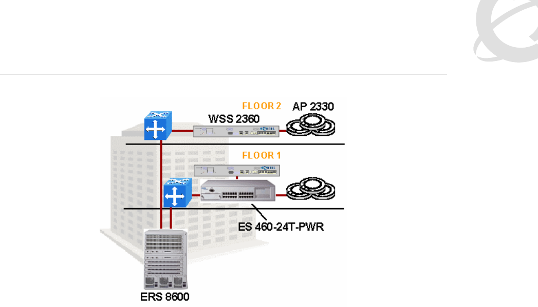
2.2.1.1 Distributed Campus
In a campus environment, there are generally two choices for placement of an AP controller (that
is, WSS)—at the edge (in a wiring closet) or in a central data center. The Distributed Campus
represents the former choice. With security switches at the edge, APs can be directly connected
and powered by the WSS 2300. This basic architecture is shown in Figure 1.
The WSS 2300 models most often deployed in this architecture are the WSS 2360 and WSS
2361. They have six PoE ports and two network ports and support up to 12 total APs. A full
complement of APs would require six to be powered by another device (injector or Power over
Ethernet [PoE] switch) and configured as DAPs. Typically, the APs utilize a mix of direct
connections and DAPs
The advantage of a Distributed Campus architecture is that it leverages the integrated PoE ports,
which can be of value to a network that does not have much PoE capability in the wiring closets.
It also allows some of the Authentication, Authorization, and Accounting (AAA) features to be
leveraged for wired users through the Wired Authentication feature. Lastly, support of third-party
APs tends to suggest a Distributed Campus architecture as well, because the third-party AP must
be L2 connected to the WSS 2300.
Voice over Wireless LAN Solution Guide v1.0 December 2005
______________________________________________________________________________________________________
Page 12
Figure 1: Distributed Campus architecture
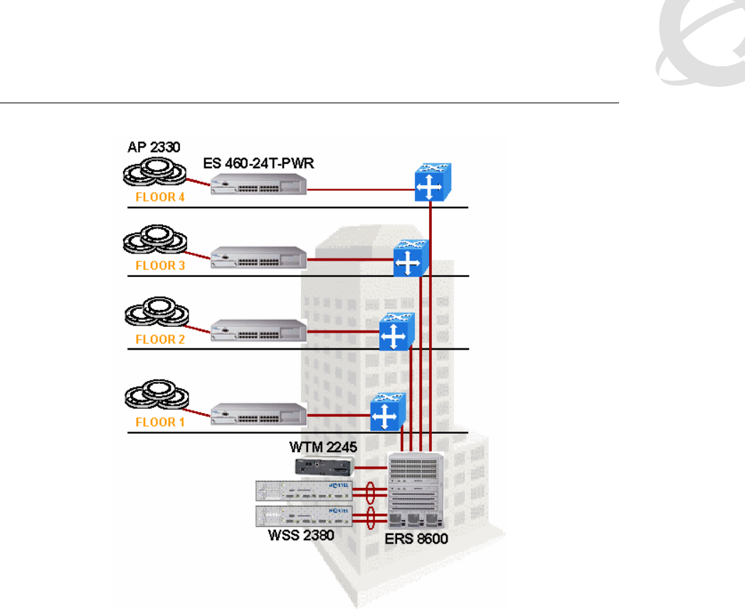
2.2.1.2 Centralized Campus
A second architectural option is to centralize the security switches within a data center
environment. The model most suited for this role is the WSS 2380, which has four gigabit
interfaces, no PoE ports, and supports up to 120 active APs. Each AP is powered at the edge by
a PoE switch or a PoE injector, and has a DAP connection back to the central WSS 2300s.
Figure 2 depicts this architecture.
There are a number of advantages to centralization. Among them are the traditional benefits of
centralization, such as reduced numbers of manageable assets, lower operation costs, and
design simplicity. Within the context of the WLAN, there are additional benefits, such as simplified
security implementation (for example, fewer firewalls to deploy), simplified VLAN structure, and
simplified client management. With this architecture, you can also better leverage many other
Nortel core network features, such as Split MultiLink Trunking (SMLT) to a Nortel Switch Cluster
Core, and N-1 active-active resiliency capabilities.
Voice over Wireless LAN Solution Guide v1.0 December 2005
______________________________________________________________________________________________________
Page 13
Figure 2: Centralized Campus architecture
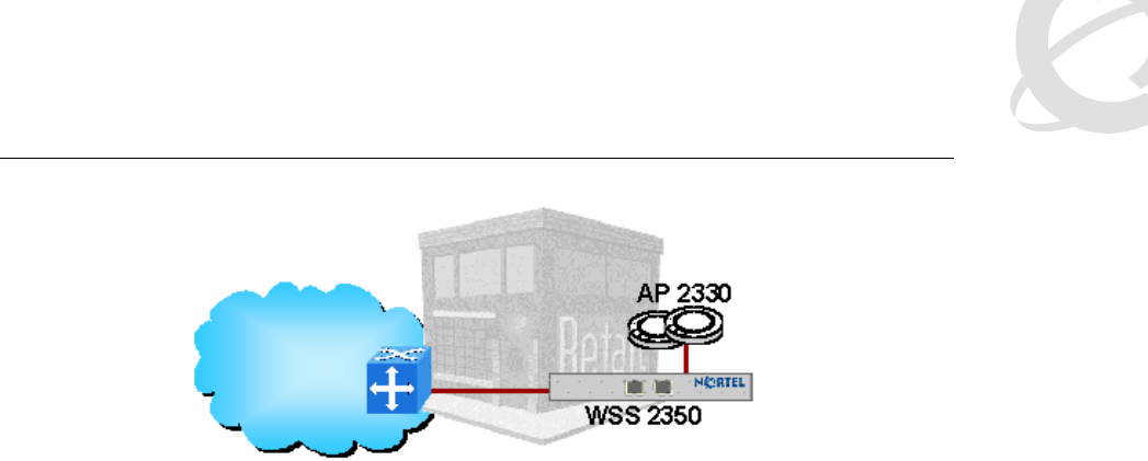
2.2.1.3 Branch Office
The WLAN 2300 can also be deployed in a small branch office environment. Usually this type of
environment requires only a handful of APs, probably anywhere from one to six. The WSS 2350
is the model best suited for this environment, supporting up to three AP 2330s per WSS 2350,
including one PoE port for direct connection. A PoE injector or PoE switch would be required to
power the remaining two APs. The most cost-effective way to scale beyond three APs is to add
another WSS 2350. If you need more than six APs, you can also use the WSS 2360, if desired.
Figure 3 shows a sample Branch Office deployment.
There have been a few different industry approaches to supporting branch office environments,
such as deploying “fat APs” or “pseudo-thin APs.” The fat-AP approach packs all WLAN features
into the AP itself, but manageability is a significant problem. The pseudo-thin AP, which moves
many control functions back into the AP (making it semi-fat), attempts to provide the best of both
worlds in the branch but in practice tends to provide the biggest limitations of both worlds. All of
these approaches either complicate the support of the WLAN solution or impose severe
limitations on the branch APs. Putting a thin AP in the branch and controlling it over the WAN is
also not a viable solution, because most WANs lack the latency and throughput needs of the thin-
AP model. The best solution is to put a low scale security switch in the branch along with the APs
so that both controller and thin AP are collocated. This solution brings the full feature set to the
branch without adding extra complications.
Voice over Wireless LAN Solution Guide v1.0 December 2005
______________________________________________________________________________________________________
Page 14
Figure 3: Branch Office architecture
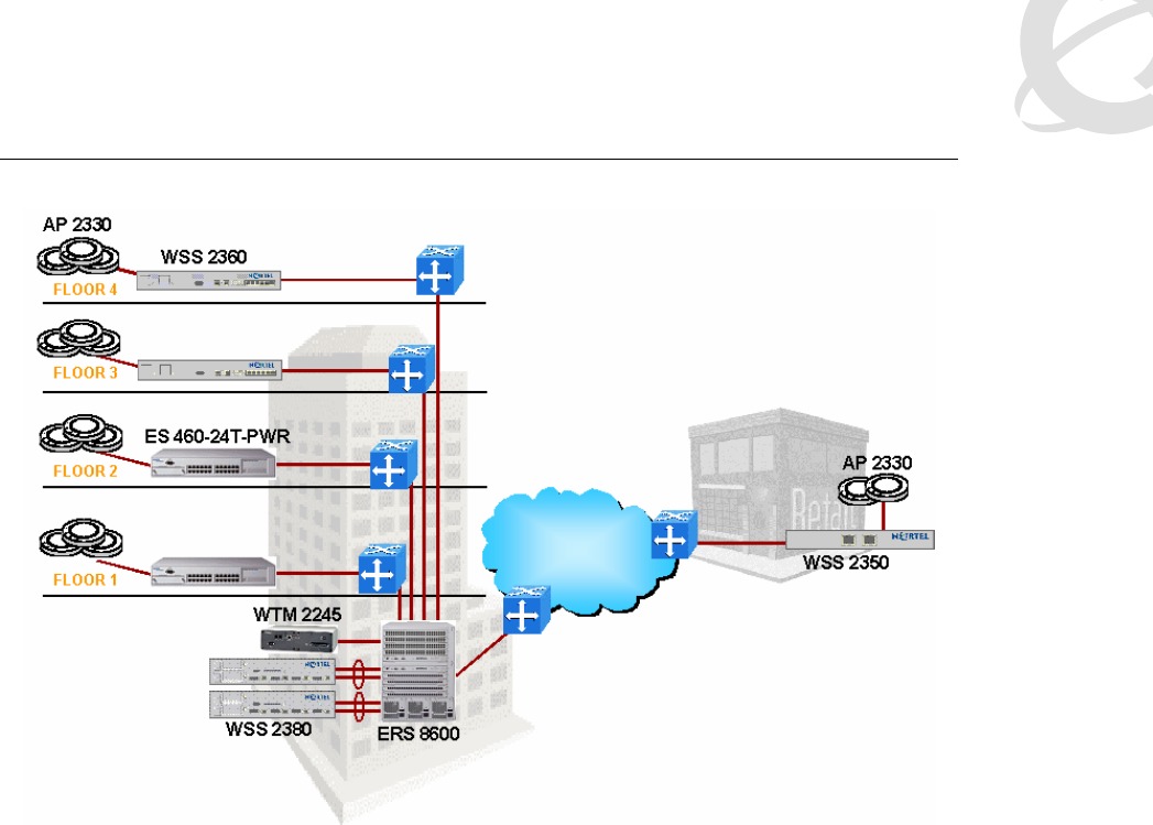
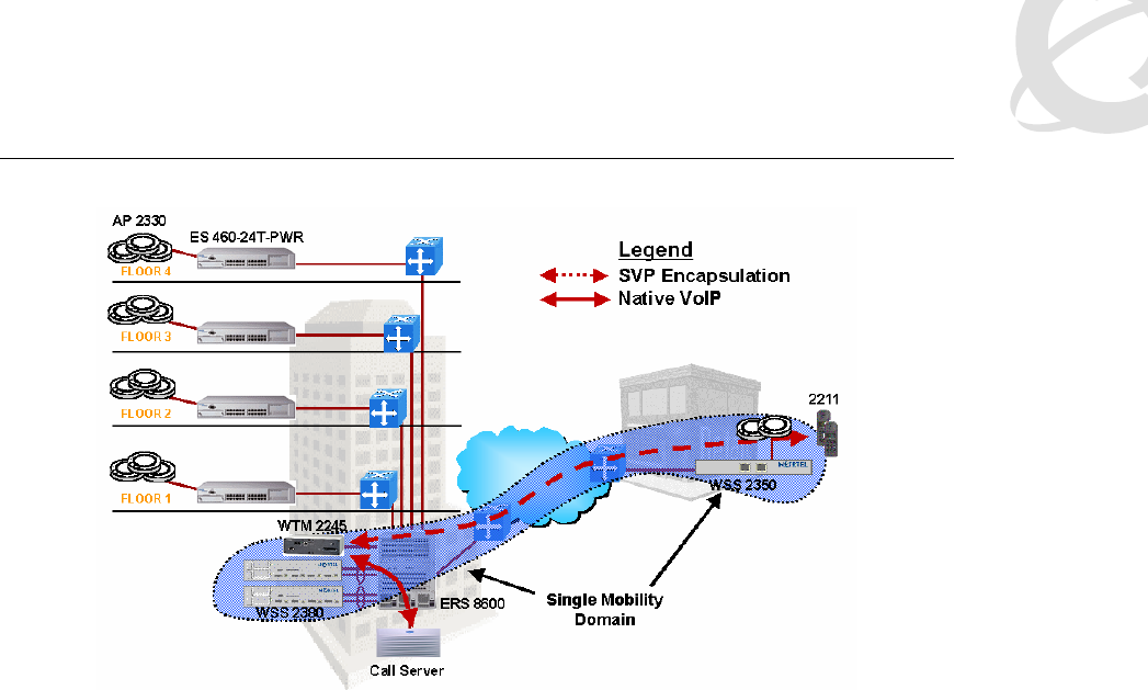
2.2.1.4 Combining architectures
Up to now, architecture has been discussed in binary terms—this topology or that topology.
However, the WLAN 2300 solution is not restrictive in this way. The three architectures can be
combined in many different ways within the same network, and as will be shown later, VoWLAN
is generally not restricted by these architectural choices. However, it is a good practice from a
supportability standpoint to maintain a level of consistency in architectural choices. Figure 4
depicts all three architectures in one network, although this design example should not be
considered a reference architecture or a best practices diagram. In this network, both the
distributed and centralized WSSs are deployed as a single Mobility Domain, which is defined as a
collection of WSSs that work together to support a roaming user.
As a general rule, branch office WSSs are either in a separate Mobility Domain, if there are
multiple switches, or in a null Mobility Domain. They should not be part of the main campus
Mobility Domain, as users do not need seamless roaming between the sites. Also not desirable is
unnecessary loading of the WAN link due to the overhead associated with Mobility Domain
statistics collection and remote VLAN connectivity. When choosing whether to include the branch
office WSSs in the main campus Mobility Domain, base your decision on both geography (Do the
sites have seamless RF coverage between them?) and WAN speeds (Is there enough bandwidth
to support users with remote VLAN assignments?). If you decide to backhaul a remote site’s
users to the campus Mobility Domain, you will need at least a T1 speed link, but you could require
higher speed depending on the numbers of users and application requirements. Within an
isolated branch office, if there is only one WSS, then no Mobility Domain needs to be defined. If
there is more than one WSS, then group them together in a unique Mobility Domain.
In general, most combined architectures are either Centralized Campus plus Branch Office or
Distributed Campus plus Branch Office. There is little motivation for combining Centralized
Campus and Distributed Campus in the same site, although there are some scenarios for mixing
architectures on individual sites. For example, a large campus may deploy WSS 2380s to support
the numbers of APs needed, a medium-size regional office may be big enough to deploy a
handful of WSS 2360s but not big enough to need a WSS 2380, and smaller branches might
employ WSS 2350s.
Voice over Wireless LAN Solution Guide v1.0 December 2005
______________________________________________________________________________________________________
Page 15
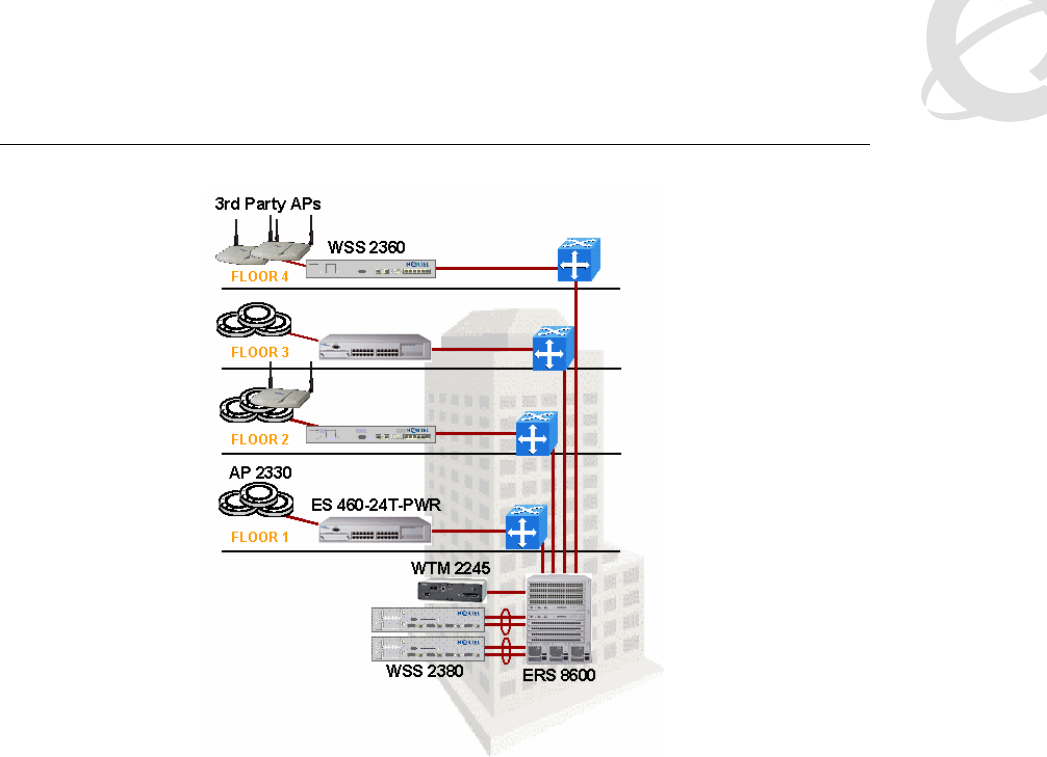
Figure 4: Combined architecture
2.2.1.5 Third-party AP support
In some cases, integrating the WLAN 2300 series into an existing fat-AP deployment may be
required or desired. For instance, fat APs may have been deployed in a limited fashion and the
WLAN 2300 is a new network expansion. The WSS 2300 extends all its AAA features to the third-
party AP, including the ability to consolidate all handsets into one voice VLAN/subnet, and QoS
classification capabilities. Figure 5 shows a sample third-party AP configuration.
Voice over Wireless LAN Solution Guide v1.0 December 2005
______________________________________________________________________________________________________
Page 16
Figure 5: Network with third-party APs
The WSS 2300 supports many models of third-party APs with a few restrictions—see WSS 2300
Release Notes. All models of WSS 2300 have support for third-party APs, although
implementation specifics may vary. In many cases, Nortel also supports VoWLAN over third-party
APs. The APs must be L2 or directly attached to the WSS 2300. Note that this may require
extending VLANs in the Centralized Campus model using WSS 2380s. The APs must be certified
by SpectraLink as SVP compliant, and configured according to SpectraLink guidelines. You must
also meet WTM 2245 engineering requirements. Details about supported third-party APs, valid
network configurations, and other restrictions are beyond the scope of this document.
2.2.2 Network design constraints
While the previous sections discussed basic design types, the intent of the following topics is to
drill down to the next level of detail and explore various design and interoperability issues starting
with the physical layer (L1) moving up to L2 and L3 constraints.
2.2.2.1 Power over Ethernet (PoE) requirements
The AP 2330 draws an average of 6 Watts (W) of power when idle, increasing to 7 W average
under heavy load. The Ethernet Switch (ES) 460-24T-POE is capable of supplying up to a
maximum of 370 W of power (assuming ES 460-24T-POE is in AC+DC mode with Network
Energy Source [NES]) in some configurations. The ES 460-24T-POE with no secondary power
source is capable of supplying an aggregate of 200 W, which is enough to power a full
complement of 24 AP 2330s (assuming a draw of 7 W per AP).
Also, you must carefully consider redundant power options for the ES 460-24T-POE if PoE is
implemented. There are two external power supply options for the ES 460-24T-POE. The first is
the Ethernet Switch Power Supply Unit (PSU) 10. In the event of a primary AC power source loss,
Voice over Wireless LAN Solution Guide v1.0 December 2005
______________________________________________________________________________________________________
Page 17
the ES PSU 10 can provide up to 75 W of power to PoE devices through the ES 460-24T-POE.
This means that when running on battery or redundant DC power, only about 10 or 11 APs can
be powered. If the deployment of the network calls for more than 10 APs on any ES 460-24T-
POE switch, Nortel highly recommends the NES as the external power supply option instead of
the ES PSU 10. The NES can provide a full 200 W to end devices from a battery or secondary
power source in the event that the ES 460-24T-POE loses its AC power source. Therefore, the
NES offers full redundancy to 24 powered AP 2330s even in the event of loss of power.
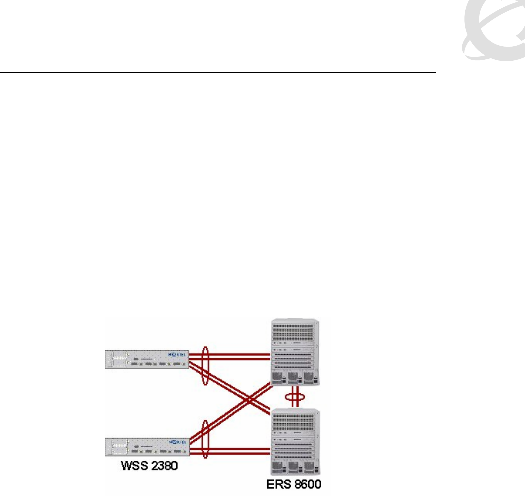
2.2.2.2 Physical layer interconnections
The WSS 2380 has four dual PHY gigabit interfaces. You can use either the integrated
1000Base-T (copper) port or the Gigabit Interface Connector (GBIC) slot for fiber connectivity.
The only GBIC currently supported is a 1000Base-SX multimode GBIC with SC interface. You
can group all four ports into a MultiLink Trunk (MLT); the preferable mode of connection to an
Ethernet Routing Switch (ERS) 8600 core is to leverage SMLT on the ERS 8600 by connecting
two WSS 2380 ports to each ERS 8600. See Figure 6. All ports are active in this configuration, so
this represents high-throughput, highly resilient mode of network connectivity.
Note that while this document refers to MLT on the WSS 2300, the underlying link aggregation
technology is 802.3ad.
Figure 6: WSS 2380 using ERS 8600 SMLT
If the WSS 2380 is connected to an ES 470-24/48T, Business Policy Switch (BPS), or ES 460
equipped with a BPS-2000-2GE Media Dependent Adapter (MDA), then you must disable auto
negotiation on the WSS 2380. If you do not disable auto negotiation, the link will not be
established. When connecting to other ES products, including the BPS or ES 460 equipped with a
BS450-1SX/SR MDA, you must enable auto negotiation. The ERS 8600 does not have any auto
negotiation issues on gigabit fiber ports, so you must enable auto negotiation on the WSS 2380
when it is connected to an ERS 8600.
The WSS 2360 has six PoE ports and two regular network ports, all of which are 10/100 physical
ports. Because of this combination, the most recommended network connectivity option for the
WSS 2360 is to aggregate the two network ports into an MLT and connect to SMLT on an ERS
8600. The other six ports remain reserved for direct device connectivity requiring PoE, most likely
2330 APs.
A WSS 2350 is usually connected through its one network port to an L2 switch in the branch. One
AP can be directly connected to the other PoE port or indirectly connected through the L2 switch
as a DAP. Another variation that adds a little more resiliency is to aggregate both ports as an

Voice over Wireless LAN Solution Guide v1.0 December 2005
______________________________________________________________________________________________________
Page 18
MLT to the L2 switch. In this configuration, all APs in the branch must be DAPs powered by the
L2 switch or a separate PoE injector.
In most cases, you should disable spanning tree on the switch port to which a DAP is connected.
If spanning tree is not disabled, there is a possibility that the AP will never connect to a WSS
2300 because of timing differences between spanning tree and the AP switch detection timers. In
the case of the ERS 8300, spanning tree does not put the port in forwarding mode before the AP
reboots to reinitiate a new connection attempt. The failed connection-reboot cycle repeats
indefinitely until spanning tree is turned off.
2.2.2.3 RF design constraints
The WLAN Handset 2210/ 11/12 and most PDAs that support the MVC 2050 are currently
802.11b-only devices. Most APs shipping today are 802.11g capable, and the IP Softphone 2050
and MCS Client run on PCs that have 802.11b, 802.11g, and 802.11a interfaces readily available.
This creates some interesting dynamics and interesting choices for network deployments. The
following points lay the groundwork for a discussion of these choices.
1. Separation of devices by multiple Service Set Identifiers (SSID) on the same radio does
not create multiple shared mediums—the devices still transmit and receive using
common radio resources on a common channel.
2. Current QoS mechanisms in the industry are most effective at protecting and
prioritizing traffic on the downstream, that is, from AP to Mobile Unit (MU). Wi-Fi
Multimedia (WMM) improves upstream prioritization by giving a statistical edge to
different classes of devices so they are more likely to transmit ahead of lower class
devices. Still other devices may cheat on the contention window to gain a statistical
advantage, though there are drawbacks to this method. The bottom line is that there is
no real arbitration or coordination between multiple devices that need to transmit
packets upstream.
3. The 802.11g devices in a mixed 802.11b/g network are statistically favored by a 2:1
ratio over 802.11b devices. This means that if there is one 802.11g device and one
802.11b device and both are trying to saturate the medium with a data transfer, for
example, the 802.11g device will transmit, on average, two frames for every one frame
from the 802.11b device. If there are two 802.11g devices for every one 802.11b
device, then on average four 802.11g transmissions will occur before one 802.11b
transmission.
4. The 802.11g transmissions take less time than 802.11b transmissions due to the higher
data rates. So even though 802.11g devices transmit more often, they spend less time
transmitting packets, which mitigates the effect of 802.11g devices being favored
statistically from the perspective of the 802.11b clients. Having too many 802.11g
devices relative to 802.11b devices upsets this balance though, so beware.
Should you enable 802.11g or maintain an 802.11b-only network? There isn’t an easy answer. If
there is a significant amount of upstream traffic from data devices, then the question becomes
unimportant. The best course of action in that case is to keep data devices off the 802.11b/g
network entirely. Large numbers of 802.11g devices can also cause problems with 802.11b
handsets on the medium. However, if instead you make those 802.11g devices actually use
802.11b for communication, the situation will likely become worse. Disabling 802.11g support and
maintaining a dual mode 802.11a/b network can make 802.11a more attractive for dual mode
data clients and reduce the amount of data devices using the 2.4 GHz spectrum. Enabling
802.11g support may increase the number of data devices sharing the 2.4 GHz channels, which
is detrimental to voice devices. As a general policy, when you have large amounts of data, use
802.11a for data and 802.11b for voice, but leave 802.11g disabled.
On the other hand, if you only have a handful of 802.11b/g capable (non-802.11a capable) data
devices and the WLAN is to be used primarily for voice, then enabling 802.11g support is

Voice over Wireless LAN Solution Guide v1.0 December 2005
______________________________________________________________________________________________________
Page 19
beneficial to overall voice quality and media scalability. These are some of the dynamics to
consider when making this choice. Ultimately you want to carefully control the number of data
devices sharing radio resources with voice devices, and you should gear your choices towards
this end.
For example, suppose that you have a large amount of Centrino laptops in the campus. If you
enable 802.11g mode, it becomes very likely that a large proportion of those laptops will prefer
802.11g (2.4 GHz) for connectivity, making it much more difficult to provide good quality voice for
handsets. If you disable 802.11g, those laptops will likely prefer 802.11a (5 GHz) because it
offers much higher throughput compared with 802.11b, and voice quality will benefit.
Another important constraint relates to maximum cell size for WLAN Handset 2210/11/12 voice
support. Ideally, an AP has a circular coverage pattern, but in reality obstacles, antenna patterns,
and orientation occlude perfect RF patterns. So instead of listing cell size in terms of distance,
Received Signal Strength Indicator (RSSI) is used instead. The outer boundary for good voice
coverage is anything better than –70 Decibels (dB). Therefore, strive to ensure that all areas of
the building are within the –70 dB range of some AP.
So far, the assumption has been that there is no interference on the 802.11b channels. But when
you deploy more than three APs, the APs themselves are a very important source of interference.
This is known as co-channel interference. Hence, it is also important to consider how channel
reuse (the term for channel plans in which more than one AP uses the same channel) impacts
network capacity. Generally speaking, you tile the channels to maximize the distance between
APs operating on the same channel. To scale capacity, you might add more APs in the same
geographic region while reducing the transmit power of each AP. But, the overall throughput
increase is not linear with the number of APs being added, meaning that total WLAN network
capacity is increased, but not proportional to the number of APs. This is an example of the law of
diminishing returns. The reason this happens is because each individual AP is losing throughput,
but the number of APs per square foot is increasing. Note that the biggest loss of per-AP
throughput occurs when going from non-channel-reuse to reusing channels. For more information
about this subject, see the whitepaper available on the Nortel web site.
The goal of this RF engineering exercise is to achieve the required call density in terms of calls
per square foot. Getting the most calls per AP is not a useful objective of capacity planning. The
parameters that must be tuned in order to engineer a voice network for capacity are channel
reuse factor (that is, the number of channels in the channel plan), transmit power of each AP, and
radius of cell (that is, based on the physical distance between APs). Due to the complexity of this
topic and simulation data required, it is not possible to discuss tuning all three variables or even
two variables at a time. A simple case study of a light to medium office environment (mostly cube
space but some walls) is provided instead. The channel reuse factor for 802.11b networks is fixed
at three (three non-overlapping channels in the 2.4 GHz range), corresponding to channels 1, 6,
and 11, so this variable is set. We fix the transmit power to 50 mW, setting the next variable. Now
we compare the effects of cell size based on the other fixed parameters. When the deployed cells
have a radius of anywhere from 33 ft to 75 ft, the call capacity per square foot is essentially the
same. This means that packing cells in tighter than a 75 ft radius per AP is a waste of money.
This example shows that in a typical office environment with APs at half power, you should
deploy APs anywhere from 100 ft to 150 ft from each other. More walls mean you must have less
distance between APs, and lowering the power of the AP lessens the required distance between
APs, both of which also serve to increase the net call density.
With respect to voice traffic from non-handset devices, calls may be placed over 802.11a or
802.11g networks. Because 802.11g has the same channel set as 802.11b, capacity planning
allows more calls per AP due to increased data rates, but the fundamental scaling limits and per-
AP radius limits remain mostly the same due to the limit of three non-overlapping channels.
Specifically, when only one channel is used capacity is much higher than 802.11b, but in an
enterprise deployment in which more than three APs are deployed and channels are reused,

Voice over Wireless LAN Solution Guide v1.0 December 2005
______________________________________________________________________________________________________
Page 20
maximum call capacity is not that much higher than the 802.11b channel reuse case (only up to
four times as much). By contrast, 802.11a offers a much greater channel space. Channel reuse
factors can be as high as 12 or more, depending on regulatory region. Borrowing the
assumptions from the previous example (50 mW transmit power and channel reuse of 12), the
same scenario has none of the same caps on call capacity. Each shrinking of cell radius results in
extra call density. Even spacing APs 66 ft apart (33 ft radius) yields more call density compared
with a 50 ft cell radius. At 33 ft radius, call capacity for 802.11a reaches as much as 5 to 10 times
that of 802.11b. Note that in non-channel reuse scenarios, capacity is substantially higher.
2.2.2.4 SSID options and limitations
The WLAN 2300 series has a feature that allows VLANs to be extended to clients over the air
while maintaining the separation of clients. This allows clients in a single SSID to be mapped to
separate VLANs, and yet privacy of each VLAN is still maintained through separate broadcast
keys.
The traditional WLAN deployment requirement was to implement separate SSIDs for voice and
for data. This requirement no longer exists, though it is still a useful deployment option in some
circumstances.
If all devices implement common security encryption mechanisms (for example, Wi-Fi Protected
Access [WPA]), then a single SSID can be offered to support both voice and data. The benefit of
this configuration is that it removes the ability of users to control to which network they connect.
This is a security mechanism that prevents curious or malicious users from putting their laptop in
the telephony VLAN. At the same time, it prevents inadvertent configuration mistakes. Either way,
the simplified user interface to the network benefits both network administrators and end users.
If data devices do not use the same encryption mechanism as WLAN handsets, then it is best to
implement multiple SSIDs—one for WLAN 221x Handsets and the other for the data devices.
This issue is not a WLAN 2300 series limitation as the AP does support multiple encryption types
on the same SSID. Rather, this is a common issue among 802.11 clients, in which a client is
confused by the beacon information indicating a different group (broadcast) key type from unicast
key type. Some but not all clients support the multiple encryption type environment.
Do not configure multiple WLAN Handset 2210/11/12 SSIDs on the same WLAN 2300 series
APs. Note that separate handset SSIDs on different sets of APs, or one handset SSID and
another non-handset SSID on the same APs are still valid configurations. The reason is that the
AP 2330 supports multiple SSIDs through multiple Basic Service Set Identifiers (BSSID), which is
to say that the AP is virtualized and appears to clients as multiple separate APs. This causes the
WTM 2245 admission control features to assume the calls are taking place on separate APs
instead of the same AP. If necessary, one way to ensure that multiple handset SSIDs on the
same AP still work without oversubscribing the medium is to cut in half the number of calls per AP
configured on the WTM 2245.
Lastly, Nortel does not recommend a closed system for VoWLAN installations that use more than
one SSID, including converged data and voice WLANs. The reason is that the SSID serves a
valuable purpose in roaming. When it is hidden by not being included in the beacon, devices have
no choice when roaming but to attempt to try all closed system APs. This can dramatically impact
call handoff times.
2.2.2.5 Layer 3 implementation
This section addresses the topic of how subnets that support client devices are overlaid on the
WSS 2300 solution. This is not referring to Control and Provisioning Protocol (CAPP) or modes of
AP/WSS connectivity over a L2/L3 network. CAPP is inherently an L3 protocol that extends an L2
environment from the AP back to a WSS. The WSS can further extend that L2 environment to yet
another WSS. But to which WSS and to which subnet does that L2 environment ultimately map?
That is the subject of this section.

Voice over Wireless LAN Solution Guide v1.0 December 2005
______________________________________________________________________________________________________
Page 21
As a new client on the network associates to an AP for the first time, it goes through the same
steps a wired client does, such as being put into a logical VLAN, issuing a DHCP broadcast,
receiving an offer, and then communicating on the network. In previous WLAN 2200 products, the
first parts were determined by local options on the WSS 2270 and SSID, meaning the WSS 2270
could only assign the user to a VLAN that was local to the WSS. This confined the IP address to
that local VLAN. Then, as the user roamed to other WSSs in other VLANs and subnets, its
presence was maintained back to the original WSS such that the IP address did not change. This
means that in a Distributed Campus architecture, the number of WLAN client subnets could be
many, and clients could potentially be in any subnet. Put differently, the main factor in assigning a
user to a subnet was simply determined by where he started out in the network, not by policy.
This not only made the network unnecessarily complex, but it made troubleshooting end-user
problems much more difficult. In such a situation, not only do you have to figure out where the
user is now, but you have to figure out which switch is currently the foreign switch and which is
his anchor switch. Another limitation to this approach is that WTM 2245s must be placed in every
subnet where phones might be used.
With the WSS 2300, initial VLAN and subnet assignments are determined by policy and that
choice is not restricted only to local VLANs and subnets. The previous example can be applied to
the WSS 2300 to illustrate the contrast. Now when a client associates to the network, the WSS
2300 can determine the proper VLAN/subnet assignment based on policy. If that VLAN is not
available locally, the WSS 2300 can find another WSS 2300 that has a connection to the
specified VLAN. The client is automatically tunneled back to that other WSS 2300, and their
DHCP discover packet is broadcast onto the remote VLAN. The “anchor” is determined by policy,
not by happenstance. As an example, all phones can be assigned to one VLAN/subnet and all
laptops can be assigned to another VLAN/subnet by policy. Even in a distributed campus, this
greatly simplifies the WLAN network. You can have as complicated an L1/L2 topology as you
want, while maintaining a very simple L3 design for client connectivity. This gives the flexibility to
integrate the WLAN 2300 series into any existing network, using either architectural philosophy,
while still allowing operational simplicity at Layer 3 and above.
The point of these examples is to provide some design recommendations based on this remote
VLAN assignment capability. Where possible, try to simplify the number of subnets that are used
for client devices. Even in a Distributed Campus architecture, you can have a few central subnets
for clients. As a general rule, Nortel recommends that you put IP phones, wired or wireless, in a
separate VLAN/subnet from data devices. This can be accomplished by providing one
VLAN/subnet for all WLAN telephony devices, as shown in Figure 7. The data client VLAN design
is an abstraction (though best practice is still to simplify). Maybe the WLAN data network has
many client subnets, or maybe one—that is unimportant in this context because the focus is
support of VoWLAN.
Voice over Wireless LAN Solution Guide v1.0 December 2005
______________________________________________________________________________________________________
Page 22
Figure 7: Single telephony VLAN implementation
Consolidating VoWLAN handsets into one VLAN/subnet has a few advantages. First, it allows the
WTM 2245 design to be greatly simplified. Instead of purchasing and deploying at least one WTM
2245 per voice subnet, you can now install one WTM 2245 for the single voice subnet. For larger
VoWLAN deployments, more WTM 2245s may be required in that single subnet to support the
number of calls, but overall fewer WTM 2245s are needed than in an equivalent multisubnet
deployment. Deciding on the number of WTM 2245s needed becomes strictly a call engineering
exercise (as it should be).
A second advantage is that external security measures are easier and less costly to implement. It
is common practice to put a telephony WLAN behind a firewall for security reasons. This is
because security features on handsets, particularly authentication capabilities, tend to lag behind
the industry. So to mitigate risks, a firewall can be used to block all but the ports needed for IP
Telephony. This practice gets complex and costly when multiplied by a number of subnets. A
more cost-effective alternative to implementing a firewall is to assign private addresses to the
handsets and let the WTM 2245 Network Address Translation (NAT) capabilities serve as a form
of secure firewall to the telephony LAN (T-LAN). Of course this is not as secure as using a
traditional firewall to secure the T-LAN.
The downside of putting all telephony devices into the same subnet is that broadcasts are
increased. Also, while security is simplified, the importance of implementing adequate security
measures increases because more devices will be impacted in the event of a security breach.
2.2.2.6 Roaming
The concept of roaming in the WSS 2300 solution is a simple one. Given the previous discussion
about Layer 3 implementation and VLANs being determined by policy, roaming is a very simple
extension. In fact, the section could be renamed “roaming upon startup” because a device being
tunneled to a remote VLAN upon connection to the network is like starting out in a roamed state
from a WSS perspective. When moving from WSS to WSS, the tunnel back to the remote VLAN
is simply moved with the device.
In the previous VoWLAN solution for the WLAN 2200 series, one of the design limits was that
Push-to-Talk (PTT) required all WSS 2270s to be physically located in the same subnet due to
roaming problems. With the WLAN 2300 series this restriction is now lifted due to symmetric
tunneling, and PTT works across WSSs in different subnets. Symmetric tunneling describes the
traffic flow in the event that a device is not local to the subnet to which it is assigned. Both
Voice over Wireless LAN Solution Guide v1.0 December 2005
______________________________________________________________________________________________________
Page 23
downstream and upstream traffic is tunneled to and from the WSS 2300 that serves the assigned
remote subnet.
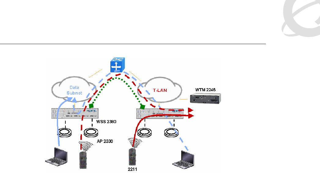
2.2.2.7 WLAN Handset 2212 VPN design
The WLAN Handset 2212 has a VPN feature that enables an IPsec tunnel to a Nortel VPN
Router, which is the only IPsec platform supported today. This alters some of the usual design
recommendations for the telephony components, such as the WTM 2245. Usually, the WTM 2245
is placed in the same subnet with the handsets. With the VPN feature enabled, the WTM 2245
now resides behind the VPN Router in a different subnet from the handsets; however, even
though the same-subnet restriction has been lifted, it is still very important to locate the WTM
2245 as close to the handsets as possible. In this case, it is placed immediately behind the VPN
Router (and in the same subnet as the VPN Router). The VPN Router must also be placed as
close to the handsets as possible. Figures 8 and 9 depict a couple of possible VPN designs.
Figure 8: VPN design over L2 networks
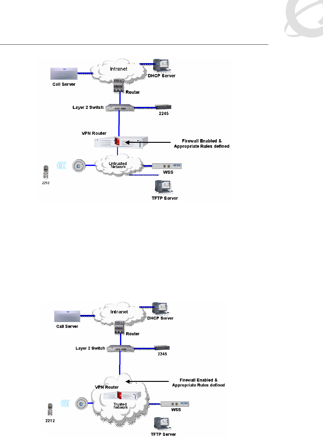
Voice over Wireless LAN Solution Guide v1.0 December 2005
______________________________________________________________________________________________________
Page 24
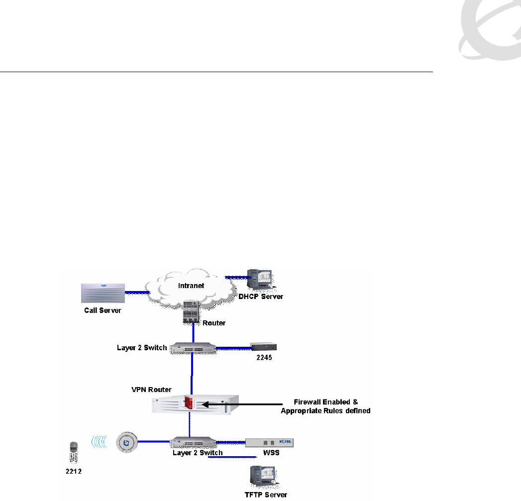
Figure 9: VPN design over L3 networks
In general, make the VPN Router public interface the default gateway for the handsets, and if not
the direct gateway for clients, at least ensure that traffic comes from the WLAN into the public
interface, not the private interface. Connect the private interface of the VPN Router to the trusted
side of the network. Ensure that client DHCP traffic flows through the VPN Router. If a network
path around the VPN Router exists for the handsets to get DHCP assignments (as shown in
Figure 10), then the routing requirements on the VPN Router become much more complicated.
To support such a scenario, you would need to set up static routes on the public interface as well
as inject those routes into the routing protocol on the private interface. Because of this, Nortel
generally does not recommend the network design shown in Figure 10 as a design for the VPN
feature.

Voice over Wireless LAN Solution Guide v1.0 December 2005
______________________________________________________________________________________________________
Page 25
Figure 10: Not recommended VoWLAN design
The VPN feature is not designed for remote connectivity over a WAN back to the corporate
network. This may in some cases work, but it is not supported. The latency, jitter, and packet loss
requirements are sure to be violated when crossing WAN connections.
If you deploy the VPN feature of the 2212 handset in a mixed network where 2211s and 2210s
are also in use, then the design recommendation becomes a little more complex. If you place a
WTM 2245 in the subnet with the 2210 and 2211 handsets, and place a WTM 2245 in the subnet
with the VPN Router to support the 2212 handsets, then there will be admission control problems
for the telephony WLAN. Each WTM 2245 will count the number of their own devices placing calls
over APs, but not count the number of calls controlled by the other WTM 2245. This creates a
blind spot for each device, and it becomes possible to oversubscribe an AP by up to 2:1! The best
solution to this problem is to have the 2210 and 2211 handsets use the same WTM 2245 as the
2212 (VPN) handsets. This WTM 2245 would be on the other (remote) side of the VPN Router
from the handsets, that is, over a routed hop—see the next section.
2.2.2.8 WTM 2245 placement and engineering rules
Usually the WTM 2245 is placed in the same subnet as WLAN Handsets 221x. This was
previously a rule, but is now just a recommendation. As was discussed in the 2212 VPN section
above, the WTM 2245 sometimes must be placed in a different subnet from the handsets.
However, the rules for delay, jitter, and packet loss still apply.
Ethernet connectivity between the WTM 2245 and the call server or other voice endpoint must
never exceed 100 milliseconds (ms) of one-way delay, 30 ms of jitter, and 2 percent packet loss
end to end regardless of the physical properties of the link. Whether or not the WTM 2245 is in
the same subnet with handsets, the link between the WTM 2245 and the handset must be under
100 ms of one-way delay, 1 ms of jitter and under 2 percent packet loss.
For branch offices, you may be tempted to configure the WSS 2350 to be part of the Mobility
Domain and backhaul the telephony devices to the campus telephony VLAN, just like WSS 2300s
are configured in the campus. But because in this configuration the WTM 2245 is across the
WAN from the handsets, this design (shown in Figure 11) is not supported, except when the
above-mentioned requirements for latency, jitter, and packet loss are met. In reality most WAN
links do not meet these requirements. The proper design to support VoWLAN in the branch office
is to deploy a WTM 2245 in the branch to locally support handsets, and to configure the branch
office WSS as a separate Mobility Domain or null Mobility Domain.
Voice over Wireless LAN Solution Guide v1.0 December 2005
______________________________________________________________________________________________________
Page 26
Figure 11: Unsupported branch VoWLAN design
2.2.3 High availability designs
You can configure many of the components described in this document to provide high
availability.
2.2.3.1 Network access availability
The WSS 2300 in coordination with the WLAN Management System 2300 can provide high
availability from an RF coverage perspective, known as Auto-RF. Assuming RF coverage has
been engineered with enough spare AP power budget for each AP to be able to provide backup
coverage, when an individual AP 2330 fails, other nearby 2330 APs can potentially increase
power to fill the coverage hole. This implies a physical deployment of APs that is dense enough to
operate at reduced power output and yet still cover the entire building. The auto-tuning feature
controls the reduction of power to minimize co-channel interference and also controls the
increase in power to cover the hole should an AP fail. Note that the site survey must be
conducted with APs at full power in order to ensure redundant coverage capabilities throughout
the building. After ensuring that coverage, enable the auto-tuning feature in order to scale the
operational power output back to the proper lower value.
Auto-tuning has two separate components, auto-tune channel and auto-tune power. Auto-tune
channel should either be disabled (preferred) or configured with a long interval on the order of
hours. This minimizes the number of channel change events that can occur. Auto-tune power has
another capability that allows it to increase power based on client connectivity issues.
Retransmissions or other connection issues will first trigger a reduction in data rate down to a
configurable minimum. After reaching this minimum, the power is then increased 1 dB at a time
up to a configurable maximum power setting (specified in dB referenced to 1 milliwatt [dBm]).
This particular feature is very undesirable given the aggressive roaming algorithm of handsets.
The problem that occurs is that as the connection becomes marginally bad, the AP increases
power to compensate, thus increasing the cell size and increasing the interference to other APs.
Instead of roaming like it should, the handset first causes the AP to increase to maximum power
before eventually roaming as it continues to move away from the AP. It is not desirable to have
an AP increase to maximum power when there is another AP nearby that can adequately service
the needs of the device. So if you implement auto-tuning power, set it up in such a way that the
maximum that auto-tune power will increase to is no more than 1 or 2 dB more than the current

Voice over Wireless LAN Solution Guide v1.0 December 2005
______________________________________________________________________________________________________
Page 27
radio power setting. Another option is to set the minimum data rate before client-driven power
changes occur to be 2 Mbps or less. This ensures that the handsets will roam (if possible) before
power increases occur. In some cases it is better to turn off the auto-tune power feature
altogether for the 802.11b radios.
2.2.3.2 WLAN Security Switch 2300 connectivity
As mentioned previously, the ports on all WSS 2300 models can be grouped as an MLT so that
you have active-active link redundancy between the WSS and other network devices. For high
resiliency, this can be used in coordination with the SMLT capability on the ERS 8600.
2.2.3.3 N+1 WLAN Security Switch 2300 redundancy
The WSS 2300 has N+1 redundancy capabilities, but because of the varying sizes of models,
figuring out the number of WSSs can be a little more involved than with other N+1 redundancy
schemes. If the network is homogeneous with respect to WSS models, the calculation is simple.
For example, after you determine the number of WSS 2380s needed to support the desired
number of APs, add an additional WSS 2380 to the network.
But if there is a mix of WSS models, the N+1 calculation becomes more complex. The first step is
to figure out the number of APs and number and types of WSSs needed. If this includes WSS
2380s, do not forget to include license information (that is, one 2380 might have 40 licenses and
another 80, according to the network design). After you determine this information, you attain N+1
redundancy by identifying the largest WSS in the design and duplicating it. For N+2 redundancy,
identify the largest WSS followed by the second largest, and duplicate both of them in the
network design. For example, if the network has one WSS 2380 with 120 licenses, one WSS
2380 with 40 licenses, and 10 WSS 2360s, N+2 redundancy is achieved by adding one more
WSS 2380 with 120 licenses and one more with 40 licenses. Alternatively, adding two WSS
2380s with 80 licenses each accomplishes the same thing.
AP failover preferences are configurable on a per-AP basis. This means that instead of the AP
simply finding a surviving WSS and attaching to it, you can configure a backup WSS for the AP to
go to in case its preferred WSS fails. Several primary (high bias) and several backup (low bias)
WSSs can be assigned per AP. In the case of multiple WSSs at the same bias level, the WSS
with the most available AP slots is preferred. When configuring explicit fallback WSSs, keep in
mind that each backup AP configuration counts against the configured AP limit of a WSS. This
limit is not the same as the active AP limit of a WSS, but is roughly 2.5 times higher for each
WSS model. For example, a WSS 2380 can support up to 120 active APs, but can have up to
300 AP configurations stored. This means a WSS 2380 can control any of 300 different APs (if
configured this way) as long as no more than 120 of them are active APs at any given time. The
WSS 2360 can have up to 30 configured APs, with only 12 active at a time, and the WSS 2350
can have up to eight configured APs with only three active at a time.
As a general best practice, after you determine the number of WSSs, divide the number of APs
evenly, proportionally speaking, among the WSSs. Then configure the backup preferences as
desired. Another option is to use the auto-DAP feature to let APs find any available surviving
WSS rather than explicitly configuring backup low bias connections to specific WSSs. To do this,
you configure a generic auto-DAP on the WSS 2300 as though it is a real DAP. When a DAP
boots up, it will attempt to find its primary WSS 2300 (that is, its high bias WSS). If that WSS is
not available, it is then directed to the least loaded WSS with an auto-DAP profile configured. The
generic auto-DAP configuration is applied to that AP, and the AP becomes operational.
If a WSS 2300 fails, there is a time lag between that event and the detection of the event by the
AP 2330. During this interval, the traffic streams of any associated devices are interrupted
because they are associated to an AP that has no data path to the network. The AP has not yet
detected that the WSS 2300 is down, so it will not disassociate devices or force them to roam. In
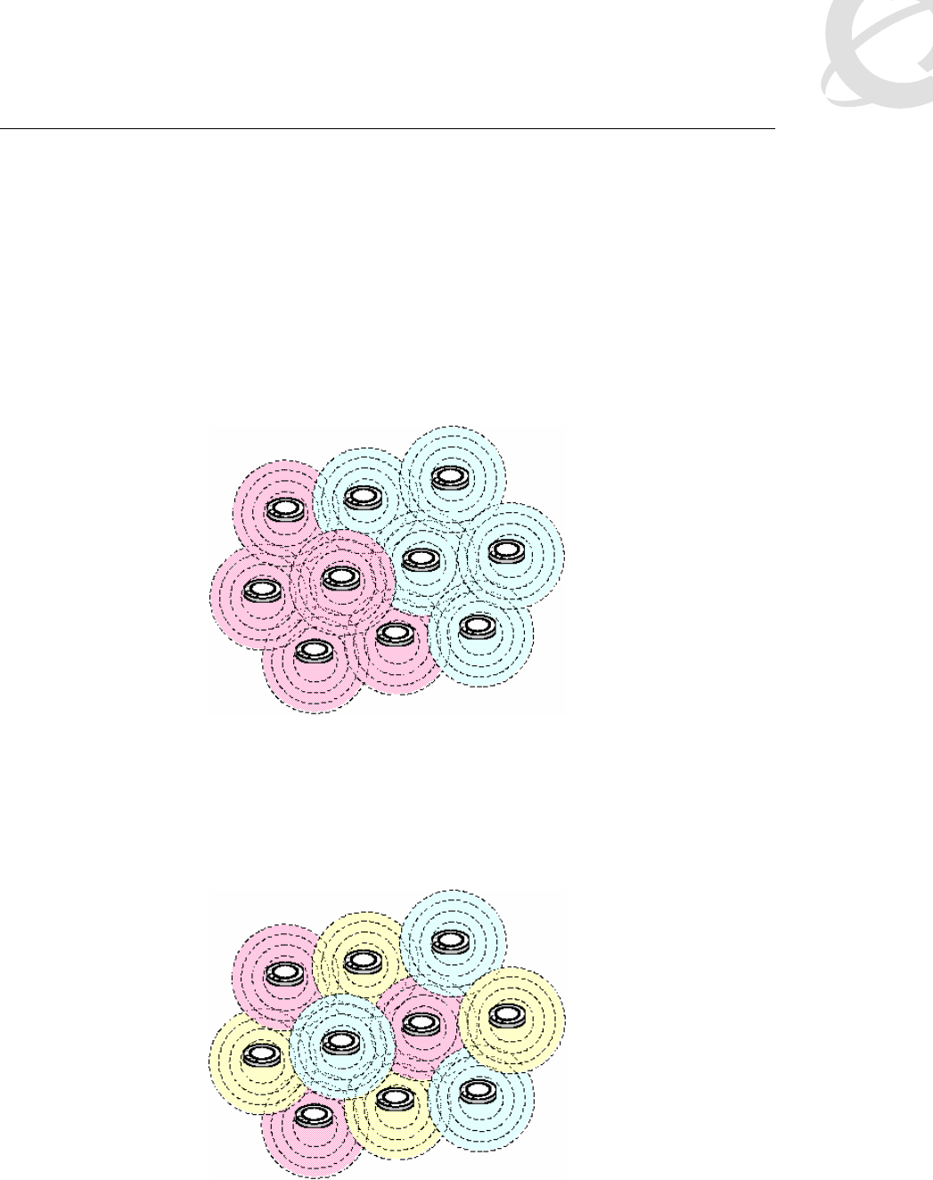
Voice over Wireless LAN Solution Guide v1.0 December 2005
______________________________________________________________________________________________________
Page 28
other words, the user device will not be aware of any problem with the WLAN (other than that
traffic flow has stopped) until the AP 2330 detects the WSS 2300 failure.
After the detection, the AP resets and associates to a surviving WSS 2300 according to bias
settings. The entire time for the AP to become operational again from the point of WSS 2300
failure can be anywhere from 45 seconds to a minute. Any existing calls on an AP 2330 will be
impacted. If a neighboring AP is associated to a working WSS 2300, then the handset will attempt
to roam to it when the current AP resets. However, this roam will very likely take place after the
call has been lost due to the lengthy interruption.
When the WSS 2300 is repaired, the APs do not automatically return to its high bias switch. This
minimizes disruption in the network until a convenient time of the administrators’ choosing, when
APs are reset and returned to their proper WSS 2300.
Figure 12: Poor redundancy planning example
Because of the previous scenarios, it is critical when designing a fault-tolerant WLAN to
intersperse APs among multiple WSS 2300s. If a network is deployed as in Figure 12 (Pink =
WSS 2300 No. 1-controlled APs, Blue = WSS 2300 No. 2-controlled APs) such that large clusters
of APs belong to the same WSS 2300s, then an outage will leave a very large hole that cannot be
covered by either devices roaming to neighboring APs or by auto-tuning increasing power of
neighboring APs.
Figure 13: Better redundancy plan
Figure 13 illustrates a better design that yields a much higher number of devices with alternate
APs to which to roam. Note that a third WSS 2300 (yellow) is added to the pattern. This is

Voice over Wireless LAN Solution Guide v1.0 December 2005
______________________________________________________________________________________________________
Page 29
because three is the minimum number that can be tiled such that no two neighboring APs are
controlled by the same WSS 2300. In this scenario, if any one WSS 2300 fails, the impact to RF
coverage will be reduced. The affected cells will still have the main outage during the interval
between failure and detection. However, during the reset after the failure is detected, the
resiliency will be much improved. The cells that are lost during the power cycle are surrounded by
cells that are still providing coverage. So client devices are able to roam to another working AP in
the meantime.
2.2.3.4 Subnet high availability
An easily overlooked aspect of high availability with the WLAN 2300 solution is access to
VLAN/subnets. Because the MU can be assigned to a VLAN by AAA, that VLAN should also
have multiple WSSs connecting to it. This way if a WSS fails, another WSS can offer connection
to the assigned VLAN/subnet. Put differently, if only one WSS has a connection to the “blue”
VLAN, and that WSS fails, any device assigned to the “blue” VLAN will no longer have access to
the network. So VLAN/subnet redundancy is accomplished by ensuring that each client VLAN
has at least two WSSs connected to it. Similarly, if you are configuring N+2 WSS redundancy as
in the previous section, then design the network such that every client VLAN/subnet has at least
three WSSs connected to it. The network is no more redundant than the least redundant
component.
2.2.3.5 WLAN Telephony Manager 2245 high availability
The WTM 2245 has limitations to high availability. There are some types of failure that can result
in complete outages. Every group of WTM 2245s in a single subnet has a master node. If this
node fails or connectivity to it is lost, the entire WTM 2245 group will not survive. All active calls
will be lost and no future calls can be placed until the master WTM 2245 is replaced (either by
installing a spare or by reconfiguring one of the slaves to be a master).
On the other hand, if one of the slave WTM 2245s fails, then the group as a whole will survive,
although some individual calls may be lost due to the reassigning of handsets throughout the
group. Keep in mind that one less WTM 2245 also means that the call capacity of that node is lost
until the WTM 2245 is replaced.
2.3 Security
Given that not all devices support the same security features and that amongst security features
some are more secure than others, it is sometimes desirable to implement multiple SSIDs and
customize network security and network access according to devices and security features
implemented. For example, a data SSID can be configured to require 802.1x authentication with
WPA2, while a voice SSID that has limited connectivity to the network implements WPA pre-
shared key (WPA-PSK) and Media Access Control (MAC) authentication. The general rule of
always requiring separate SSIDs for different security types no longer applies. The only invalid
combination for the AP 2330 is the mix of encrypted types and clear access together on the same
SSID. All other mixes of encryption types, like WEP + WPA + WPA2, are valid possibilities. Today
the main drivers for separate SSIDs are client dependencies and commonsense security
practices. An example of the latter is to avoid mixing static Wired Equivalent Privacy (WEP) and
WPA2 on the same SSID because the broadcast key used in such a scenario is the static WEP
key.
Client dependencies are more complex. Some devices will not associate to an AP that allows a
mix of encryption types, and others will. In particular, the WLAN 221x handsets will not work in a
mixed encryption environment. So if a combined handset/data SSID is desired, ensure that the
encryption type is the same for both devices. For example, laptops using 802.1x+WPA2 and
handsets using WPA2-PSK will work, but laptops using WPA2 and handsets using WPA will not.

Voice over Wireless LAN Solution Guide v1.0 December 2005
______________________________________________________________________________________________________
Page 30
2.3.1 WLAN Handset 2210/11/12 security features
For authentication, the WLAN Handsets 2210/11/12 support either open, WEP shared key, or
WPA/WPA2 pre-shared key (PSK) mechanisms, while the 2212 model also supports IPsec VPN.
Note that the WLAN 2300 series can additionally use MAC authentication to increase the level of
confidence in authentication.
For data encryption, the 2210/11/12 handsets support 40-bit and 128-bit WEP, WPA, and WPA2
and the 2212 supports 3DES for VPN encryption. If you use WEP, Nortel recommends that the
authentication type be set to open, due to the known weakness of the 802.11 shared key
authentication algorithm. This is counterintuitive. For WPA and WPA2, the use of PSK does not
pose the same security risk that WEP shared key authentication does. Choice of WPA2 pass
phrase is important, however—weak ones can be broken through dictionary attacks. The
configuration cradle is especially valuable for configuring complex and secure pass phrases.
Bear in mind that the WEP encryption algorithm is compromised and will not thwart determined
attackers and eavesdroppers. Even 128-bit WEP is only roughly twice as secure as 40-bit WEP,
which means the effort to program many handsets with 128-bit keys may not be worth the effort
put into it in the long run. For best handset security on 2210 and 2211 models, implement WPA2-
PSK; for best handset security on the 2212 model, implement IPsec VPN.
2.3.2 IP Softphone 2050 and MCS Client security features
The IP Softphone 2050 and MCS Client security features are as wide and flexible as are 802.11
Network Interface Card (NIC) security features. This is one key advantage of the PC-based voice
applications. Most current NICs can support 802.1x clients, IPsec clients, government grade
security protocols such as Fortress and Cranite, and WPA. Essentially, any mechanism that is
desired for protecting data and is required for laptops can be easily leveraged to secure voice
over the WLAN. Battery power is generally not a major issue in laptops, and should not unduly
influence what security measures you implement.
2.3.3 MVC 2050 security features
Supported PDA models do support the more robust 802.1x protocol for authentication and can
dynamically rotate WEP keys for encrypting data. Dynamic keying dramatically increases the
security of WEP-based encryption, because the keys can be changed before being compromised
by an attacker. Some models of supported PDAs also support WPA for more robust security—
consult the manufacturers’ web site for more information on particular PDAs. Alternatively, you
can use the Movian IPsec client for securing voice. But this comes at a penalty of slightly reduced
battery life due to the high CPU use of the client. However, the CPU usage itself has a bigger
potential impact because Movian client adds about 20 percent utilization, and calls destabilize at
about 70 percent utilization. Maximum talk time varies with the particular PDA and battery, but
with the Movian client running it will be a little less than the normal maximum.
The optimal compromise that maximizes battery life while providing good enough security on a
PDA is to implement 802.1x and dynamic WEP keying.
2.3.4 Minimum security recommendations for WLAN 2300
Configure the WLAN 2300 series with a single SSID for both data and voice if the following
requirements can be met:
Common encryption type between data devices and handsets
The use of MAC authentication plus PSK authentication for handset devices is
considered acceptable from a security policy perspective
Whether or not you implement handset voice with a separate SSID, the WLAN 2300 series
should implement either WPA2-PSK, or MAC authentication, but preferably both. Alternatively

Voice over Wireless LAN Solution Guide v1.0 December 2005
______________________________________________________________________________________________________
Page 31
WPA-PSK plus MAC authentication is suitable. For WLAN Handsets 2212, Nortel also
recommends use of IPsec from a security perspective. In most cases, avoid WEP. Note that
Nortel does not recommend mixing VPN handsets and WPA/WPA2 due to the complexities
involved. Separate SSIDs are required and MAC authentication rules can potentially become
complex. In most cases, it is best to try to find a common encryption type amongst all devices and
implement that uniformly. If you have PDAs, WLAN Handsets 2212, and laptops, IPsec VPN is a
very viable option.
You can implement MAC authentication through the local database on the WSS 2300 or on a
separate Remote Authentication Dial-In User Service (RADIUS) server. RADIUS MAC
authentication is an easier-to-manage solution because only one database needs to be
maintained, as opposed to multiple WSS 2300 databases all with the same MAC address listings.
MAC authentication must provide the VLAN name for the device, so preferably you would
configure RADIUS or the local database to supply a VLAN name that is different from the data
VLAN. Specifically, Nortel recommends that you separate voice and data into different VLANs on
the wired side even if the wireless side provides one SSID interface.
If the data network and voice network are routed together, then employ access control lists (ACL)
on the WSS 2300 series to prevent access to the data network from the voice SSID. Only the T-
LAN should be accessible from the voice SSID. If the only VoWLAN terminals deployed are
WLAN Handsets 2210/11/12, a particularly effective (and recommended) packet filter on the WSS
2300 is one that only allows SVP traffic to and from the voice VLAN. SVP is easily identified by IP
Protocol Type 119 (0x77). Alternatively, the filtering function can be offloaded to a dedicated
firewall device. The advantage of this is that it avoids the performance impact of ACLs being
processed in software by certain models of WSS 2300. The WSS 2380 can perform this at wire
speed, but other WSS models cannot. A dedicated firewall would likely be stateful, whereas the
WSS 2300 ACLs are just basic packet filters. If the voice VLAN is not logically routed to the data
network then perhaps additional ACLs are not needed on the WSS 2300. They can still be used
as an additional layer of protection, though. An alternative option, instead of implementing a
separate firewall device, is to assign non-routable (private) IP addresses to handsets so that the
WTM 2245 acts like a NAT/firewall between the T-LAN and the WLAN.
If the MVC 2050, MCS Client, or IP Softphone 2050 is also used, then it is secured by the options
available to the device itself. Whether a common SSID or separate SSIDs are used depends on
the same decision points described previously. A firewall or ACL setup becomes a little more
complex because those dual type devices must have access to the data network as well as the T-
LAN (voice).
2.4 Performance and scalability
Following are the general performance and scalability expectations of each major device in the
solution. Because of the potential complexity of the solution as a whole and the dynamic
environment intrinsic to RF technology, it is hard to characterize every situation. For example,
because the WLAN Handset 2210/11/12 and MVC 2050 use different QoS mechanisms,
characterization of one does not apply to the other. In a pure WLAN Handset 2210/11/12
environment or a pure MVC 2050 environment it is easier to find the ceiling on call scalability per
AP. When you mix devices in different proportions, it becomes much more difficult to pin down
the exact expectations. So while it may seem simplistic to deal with this subject on a per-device
basis, it is really the only way to distill performance expectations into a manageable discussion
without performing endless test plans of the endless permutations of potential WLAN designs.
2.4.1 WLAN AP 2330 scalability
Each AP 2330 provides a certain amount of maximum call capacity. This is expressed as a
ceiling, and real-world conditions adjust this threshold downward. There are several factors that
contribute to this adjustment. First, sources of interference such as co-channel interference (CCI)

Voice over Wireless LAN Solution Guide v1.0 December 2005
______________________________________________________________________________________________________
Page 32
subtract from medium capacity by virtue of the resulting transmission errors and the
retransmission of corrupted frames. The impact of retransmission is far more significant on
WLANs than on 802.3 networks because collisions are not detected and remedied within the first
64 bytes of a frame. On 802.11 WLANs, collisions are detected by the failure to receive an ACK
within a predetermined window after the transmission is completed. Collisions cannot be detected
in real time by an active transmitter, which means that a 1500 byte frame will be transmitted in full
before the transmitting device deduces that the packet experienced a collision. The entire 1500
byte frame must be resent yet again, as must the other colliding transmission from the other
device.
To give an example of how this impacts call capacity, suppose that with perfect conditions with
respect to interference the maximum call capacity is determined to be 10. The assumption here is
that all 10 calls have good quality in a perfectly clean RF environment. Further assume that
maximum call capacity is defined to mean the maximum number of calls at which each call
receives good quality. So, in this situation, 11 calls create an unacceptable quality condition for all
calls. Now add interference. Supposing the result is now a frame error rate of 5 percent. The
retransmissions alone increase bandwidth consumption by almost another call equivalency. This
means you are going to have at best a quality equivalency of 11 calls, which, as mentioned
above, was previously determined not to be good enough. It is tempting to assume that simply
revising the maximum calls allowed on an AP downward to nine will resolve the quality issues.
This is not the case. More than likely, in this 5 percent error rate environment, you would have to
sacrifice multiple calls in order to get back to acceptable quality levels. It is hard to draw sweeping
generalizations about behavior of all 802.11b devices, but most devices are designed to rate
scale down to accommodate the noisy environment. For each calling device that chooses to drop
to the 5.5 Mbps rate, roughly one additional call is lost from the maximum capacity.
Other sources of interference are more disruptive to call capacity, and can ruin the suitability for
even a single voice call to be placed in a particular area. Examples of these sources of
interference are Bluetooth devices and microwave ovens. If you are near a microwave and if the
interference is significant, you will be unable to make a call. Some microwaves are better
shielded than others. This type of interference does not affect engineering numbers. In other
words, if this is the source of interference, you will not have reduced capacity, you will have no
capacity in that region.
Second, distance from an AP and corresponding rate scaling affects the realistic call capacity of
an AP. Returning to the 10 maximum call example with no interference, suppose this capacity
was determined with all users in close proximity to the AP. If two users walk away from the AP
and drop to the 5.5 Mbps rate, then those two calls now consume approximately the equivalent of
four calls at the 11 Mbps rate. So if 10 calls are active, then all 10 now have quality problems.
The solution here is to reduce the allowed number of calls to eight. The more users that are far
away from the AP, the less the total capacity for calls is on that AP. A phone that rate scales
down to the 2 Mbps rate consumes almost the equivalent capacity as three calls at 11 Mbps. So
you can see that mobility creates an additional challenge for engineering call capacity.
The third dependency is the particular device and its specific functionality and 802.11 behaviors.
Not all 802.11 devices are equal. Some have better quality RF components (antennae, for
example) and can utilize higher transmission rates at farther distances than other 802.11 devices.
Such devices scale better in terms of call capacity on an AP compared with lesser devices on that
same AP. Codecs supported and implemented also play a role. G.729 (8 kilobits per second
[Kbps]) yields very marginal increases in call capacity compared with G.711 (64 Kbps) on 802.11
WLANs. You roughly gain about a 10 percent increase in call capacity over G.711, so the loss in
speech quality to gain 10 percent more calls may not be a fair tradeoff. Devices that implement
G.729 versus those that implement G.711 are not likely to have very different scaling numbers
based on codec alone. The more important codec issue is the packetization rate. Devices that
use a 30 ms packetization rate will gain roughly 20 percent more call capacity over devices that
use a 20 ms packetization rate with the same codec. For example, assume you find that with one

Voice over Wireless LAN Solution Guide v1.0 December 2005
______________________________________________________________________________________________________
Page 33
particular handset that uses G.711 and 20 ms packetization, you can get a maximum of eight
calls on an AP. By just switching to 30 ms packetization on the same exact devices, you can now
get 10 calls on the same AP.
Given all the dependencies, it can be challenging to find the exact number of calls per AP. The
sections that follow provide device-specific information and scaling numbers.
2.4.1.1 WLAN Handset 2210/11/12
The WLAN Handset 2210/11/12 supports both G.711 and G.729 codecs, but only using a 30 ms
packetization rate. The WTM 2245 translates between packetization rates, meaning that from the
WTM 2245 to other device the call uses the packetization rate specified by the CS 1000 (for
example, 20 ms). The WLAN Handset 2210/11/12 encapsulates its voice payloads in SVP for
QoS. WLAN Handset 2210/11/12 further synchronizes communications such that the handsets
are able to avoid collisions with each other more effectively than the usual 802.11 collision
avoidance mechanisms. Each handset maintains a list of up to four APs as potential candidates
for roaming. The WLAN Handset 2210/11/12 is aggressive in roaming to other APs, which tends
to prevent it using a suboptimal data rate when another AP can provide better service. The
handsets also communicate to the WTM 2245 and discover which APs are at full call capacity, so
that the WLAN Handset 2210/11/12 can direct its call through an AP that has call capacity
available.
Under optimal conditions, meaning no interference and all devices in proximity of the AP, up to 10
voice calls from a WLAN Handset 2210/11/12 can be supported on a single AP 2330. When
configuring the maximum call parameter of a WTM 2245, never set it above 10. A more realistic
rule of thumb that allows for devices to move about and rate scale accordingly is anywhere from
six to eight calls per AP. A noisy RF environment can impact the numbers further as well. Or, if
you want to allow data devices to have some amount of guaranteed bandwidth, you can lower the
maximum voice calls per AP to keep voice calls from consuming all available throughput. For
example, limiting the maximum calls per AP to seven allows data traffic to in essence reserve 30
percent of media capacity. Likewise if the network supports other non-221x handset calls on the
802.11b network, then you must leave adequate capacity for those calls too. Note that the call
admission control function of the WTM 2245 cannot serve to limit those other voice calls on a per-
AP basis.
There is an alternative control on the WTM 2245 that affects call capacity across APs. This
control allows the WTM 2245 to fix the data rates that handsets will use. The options are
Automatic and 1 Mb/2 Mb only. When you choose the latter, maximum call capacity drops by
slightly more than half if G.711 is in use, or by slightly more than two-thirds if G.729 is in use. The
advantage of this option is that most of the variability of call capacity is removed as rate scaling
effects are eliminated. So you can get more predictable call capacity at the expense of maximum
number of calls under optimum conditions. Note that with this option enabled, throughput for
802.11b data devices will be severely impacted by even one or two voice calls.
Or, you can use the automatic option to have higher potential capacity, but with the risk of
occasionally being oversubscribed under the worst conditions. For example, if eight calls is the
configured limit on the WTM 2245, and if all eight calls are from handsets on the edge of
coverage, the cell is oversubscribed. On the other hand, if five calls is the configured limit and
handsets are restricted to 1 Mb/2 Mb, then capacity is wasted when most handsets are close that
could otherwise be used by other data devices. If you want this type of predictability, it is probably
preferable to engineer the maximum calls per AP based on 1 Mb/2 Mb rate selections in the
handsets, set that number as the call limit on the WTM 2245, and then set the actual rate of the
handsets (on the WTM 2245) to Automatic. That way, the WLAN is engineered for the worst
case, but in optimal conditions, more throughput is left over for other devices to use, due to
handsets using higher data rates. In summary, you should never actually use the 1 Mb/2 Mb
option, even if the network is engineered to that type of coverage.

Voice over Wireless LAN Solution Guide v1.0 December 2005
______________________________________________________________________________________________________
Page 34
2.4.1.2 IP Softphone 2050 and MCS Client
Providing scalability rules for the IP Softphone 2050 or MCS Client may appear meaningless in
this context because the phone runs on the same PC with other data applications. A pure voice
capacity number is not going to provide much engineering guidance because that same PC can
also send large amounts of data on the medium. However, it is much easier to design a VoWLAN
when you can take advantage of a higher speed NIC in a PC such as an 802.11a interface. The
exact limit has not been determined through testing, but as a rule of thumb you can expect to get
as much as 3.5 times as many calls as you can on an 802.11b network, roughly in the
neighborhood of 30 to 35 calls if all laptops are next to the AP. As mentioned earlier under
channel reuse scenarios, the difference in capacity is 5 to 10 times that of 802.11b under channel
reuse scenarios. Both are significantly lower numbers, depending on network load, than the
corresponding non-reuse call numbers per AP. Whatever the maximum number of calls per AP, it
is wise to use a more conservative number given that the network (upstream packet flow) will be
supporting data at the same priority level as voice and given that PCs in reality will be scattered
across the coverage area and will be rate scaling downward.
Similar numbers can be applied for 802.11g networks if the network is homogeneous with respect
to 802.11g devices, compatibility mode (the mechanism required when 802.11g and 802.11b
clients coexist on the same WLAN) is not currently running, there is no data traffic, and there is
no channel reuse. If the network is running in compatibility mode, the numbers become
ambiguous due to the variety of protection mode mechanisms and possible implementations of
those variants. In a best case, with no active 802.11b traffic or other data traffic, it can still be as
high as 20 to 25 calls from 802.11g devices. But again, like in the 802.11a case, such numbers
quickly become meaningless upper bounds when reality will dictate less optimal conditions.
The IP Softphone 2050 and MCS Client also pose a number of additional challenges, such as
when you use a multimode NIC in combination with other voice devices on the WLAN. You can
plan to have WLAN Handsets 2210/11/12 on the 802.11b WLAN and laptops on 802.11a. The
WTM 2245 is able to accurately count the number of voice calls on the 802.11b radios. If a
multimode NIC on a PC chooses to use the 802.11b radio for some reason, you now have calls
traversing the 802.11b network that are not counted by the WTM 2245. Therefore, Nortel
recommends that when you deploy WLAN Handsets 2210/11/12 together with PC-based voice
applications (IP Softphone 2050 or MCS Client) in the same network, confine the PC-based voice
applications (as much as possible) to the 802.11a channels. You must also account for the QoS
mechanisms of the PC itself, which may not be very robust in terms of prioritizing applications.
Discussion of PC operating system features and NIC device drivers is beyond the scope of this
document.
2.4.1.3 Mobile Voice Client (MVC) 2050
It is difficult to determine a rule of thumb for the MVC 2050 on a PDA because there are multiple
types of hardware and corresponding drivers on which the client can be installed. Not all PDAs
are equal, nor are all drivers for a particular device equal. The MVC 2050 also supports
packetization rates of 20 ms and 30 ms with G.711 A-law and µ-law, so capacity will vary with the
packetization. G.729 and G.723 are not supported codecs today on the MVC 2050. Contrast the
level of options on PDAs with the uniformity of the WLAN Handset 2210/11/12, whose fewer
permutations make engineering easier. For PDAs there is no way to provide a blanket
supportability statement such as “Ten MVC 2050 voice calls per AP 2230.” Any guideline must be
determined per make and model of PDA with driver and codec dependencies. With the latest
drivers installed, Hewlett Packard (HP) iPAQs have been tested with up to eight voice calls per
AP. As a general rule with PDAs, the engineering limit is six to eight calls per AP depending on
model and driver version.
A mixed environment likely has performance metrics proportional to the mix of devices in use. For
example, if half the PDAs are iPAQs and iPAQs are known to scale up to 8 and Dell Axims make

Voice over Wireless LAN Solution Guide v1.0 December 2005
______________________________________________________________________________________________________
Page 35
up the other half and were known to scale up to 10, then likely the resulting mix may scale to
about nine calls per AP.
There is another important difference between the PDA and WLAN Handset 2210/11/12.
Because the WLAN Handset 2210/11/12 has a companion device, namely the WTM 2245, per-
AP call capacity can be tracked and ultimately enforced. The MVC 2050 does not use the WTM
2245 and number of calls per AP cannot be enforced. Any such similar call admission control
feature would have to be implemented on an AP such that the AP could not only determine the
number of PDAs associated but also identify a voice call from other data traffic to and from the
various PDAs. The point is that there is no way to enforce call admission control per AP today.
Note that this same distinction also applies to the IP Softphone 2050 and MCS Client.
2.4.2 Battery life conservation
Devices that utilize the power-saving features of 802.11 sometimes power off their radios for
periods of time to save battery life, though the WLAN Handset 2210/11/12 only sleeps when on-
hook, not in the middle of a call. It is still required to listen to certain beacons: every n-th beacon
as specified by client, and every beacon containing a Delivery Traffic Indication Map (DTIM).
Default values on the WSS 2300 have the AP 2330 sending beacons every 100 ms with a DTIM
in every beacon. Increasing both the beacon interval and DTIM interval can extend the battery life
of power-saving devices. The higher the values, though, the less responsive power-saving
devices are to incoming traffic, such as calls. Higher values also cause broadcast and multicast
rates to become more constrained, because multicast traffic is also distributed at DTIM intervals.
You should derive optimal values based on the applications and devices in use on the network
and their associated benefits to battery life. There is no recommended setting that fits all design
scenarios, so keep the default settings unless there is a specific need to tune these parameters.
2.4.3 WLAN Telephony Manager 2245 scalability
The number of calls an individual WTM 2245 can support is dependent on the number of WTM
2245s in the subnet. Assuming a 100 Mbps full-duplex connection to the network, a single stand-
alone WTM 2245 can manage up to 80 active calls. If two WTM 2245s are installed (master/slave
configuration) then each can support up to 64 active calls for a total of 128 calls. Table 1 lists the
call capacity scaling numbers when additional WTM 2245s are added. Note that if you deploy one
WTM 2245 in each of two subnets, then each is the master of its subnet and each can support 80
calls. Each independently tracks handsets, associations, and so on. This point is important
because it shows the need to have one handset subnet per geographic site or Mobility Domain.
As an example, if you have two subnets for handsets in a campus and you are directing through
AAA some handsets to one subnet and some to the other, then you have two Call Admission
Control domains operating independently. Specifically, if both specified a limit of seven calls per
AP, then it would be possible to have seven calls admitted by each respective WTM 2245 on the
same AP—the AP would be oversubscribed by 2:1! If multiple subnets are required for some
reason, the best way to support this configuration is to leverage the L3 WTM 2245 design in
which the WTM 2245s are all in one subnet but SVP is routed from the second client subnet.
While this is now a supported configuration, all the engineering guidelines for latency, jitter, and
packet loss must still be maintained. Note that the L3 design guidelines for having clients and
WTM 2245 in different subnets does not mean that the WTM 2245 master and slaves can also be
separated by routers—they must still be collocated in the same VLAN/subnet.

Voice over Wireless LAN Solution Guide v1.0 December 2005
______________________________________________________________________________________________________
Page 36
WTM 2245s Calls per
WTM 2245 Total
Calls Erlangs
#Handsets
10% use #Handsets
15% use #Handsets
20% use
1 80 80 65 500 433 325
2 64 128 111 1000 740 555
3 60 180 160 1500 1067 800
4 58 232 211 2000 1407 1055
5 57 285 262 2500 1747 1310
6 56 336 312 3000 2080 1560
7 56 392 367 3500 2447 1835
8 55 440 415 4000 2767 2075
9 55 495 469 4500 3127 2345
10 55 550 524 5000 3493 2620
11 55 605 578 5500 3853 2890
12 54 648 621 6000 4140 3105
13 54 702 674 6500 4493 3370
14 54 756 728 7000 4853 3640
15 54 810 782 7500 5213 3910
16 54 864 836 8000 5573 4180
Table 1: WTM 2245 Scaling
The number of handsets a WTM 2245 (or group of WTM 2245s) can support is similar to a voice
trunk engineering calculation and is beyond the scope of this document. As an example of how
WTM 2245 capacity calculations differ from a pure call capacity number, a single WTM 2245
could support an aggregate of 500 handsets if no more than 15 percent are making calls
simultaneously.
2.5 QoS
This section addresses QoS from an end-to-end perspective. It is not enough to cover just the
QoS features of the WSS 2300, WTM 2245, and AP 2330 when there is other equipment
connecting those devices together.
2.5.1 WLAN Security Switch 2300 and WLAN AP 2330
The WSS 2300 and AP 2330 work together to solve some aspects of the over-the-air QoS
problem. These products support the SpectraLink Voice Priority (SVP) protocol by providing
prioritization of SVP packets. SVP has a number of QoS features in addition to the functionality
provided by the WLAN 2300 products. For non-SVP-based voice traffic (that is, MVC 2050, IP
Softphone 2050, and MCS Client), the WLAN 2300 series can still provide SVP-like prioritization
to the traffic through ACLs. In general, though, the WLAN 2300 series prioritization of SVP-based
voice will result in an overall higher quality voice experience than WLAN 2300 series prioritization
of non-SVP-based voice devices. This higher quality is due to the additional QoS features that
SVP offers between end devices, not because of any difference in the way the WLAN 2300 series
performs prioritization of the two types of calls.
The WSS 2300 and AP 2330 also support WMM for over-the-air QoS. One key advantage of
WMM over SVP is that WMM specifies four distinct classes of traffic instead of the binary
distinction offered by SVP, that is, SpectraLink voice and everything else. This capability is key to
supporting true multimedia over WLAN. SVP and WMM are not incompatible technologies with
respect to implementation on a WLAN; however, there are some limitations to support of WMM

Voice over Wireless LAN Solution Guide v1.0 December 2005
______________________________________________________________________________________________________
Page 37
and SVP in combination on the WLAN 2300 series. The WLAN Handsets 2210/11/12 also
support WMM, but note that as of today, the officially supported VoWLAN solution between
handset and WLAN 2300 series requires that you not enable the WMM features. That is, you
must turn off WMM on the WLAN 2300 series when using WLAN 2210/11/12 handsets on the
network.
The following sections describe SVP and WMM and discuss the operational differences on the
WLAN 2300 series when WMM is enabled or disabled.
2.5.1.1 SVP description
SVP functions can be broken down into two categories: those functions requested or required by
an access point, and those that are implemented on the handsets and WTM 2245 that go beyond
the capabilities of an access point. The SVP specification requests a number of behaviors from
any access point, mostly related to priority processing of voice and SVP packets. An access point
must service SVP packets before all other packets, while taking care not to reorder high priority
packets to or from the same device. Access points should also use a zero backoff contention
window size for transmitting these high priority packets. This ensures that the AP can transmit
before any other device that is using the medium. Lastly, retransmission of a corrupted packet
should not delay other voice frames that are queued for other voice devices. Normally when an
error occurs in transmission, a longer backoff period is used, followed by the retry. Any frames in
the queue normally must wait for this transmission to be completed or fail after the maximum
number of retries. Because this creates a situation in which one problematic high priority device
can impact all other high priority devices, SVP also requests that the AP move on to service other
high priority devices before returning to retransmit the corrupted frame. The WLAN 2300 series
implements all elements required by SVP, and is certified through lab testing as an SVP
compatible product.
The remaining SVP capabilities are implementations of the WTM 2245 and WLAN Handsets
2210/11/12. The WTM 2245 has an admission control feature that enables it to keep track of the
AP to which WLAN Handsets 2210/11/12 are associated. The WTM 2245 therefore knows how
many active calls are on each AP, and takes action. After the maximum number of per-AP calls is
determined by the engineering/design process, that number is programmed into the WTM 2245.
When an AP reaches that number of calls, the WTM 2245 prevents additional calls from using
that AP. An idle device that is associated to the “full” AP and setting up a new call will be
instructed to roam before making the call. A device with an established call that is attempting to
roam to the “full” AP will be instructed not to roam to that AP.
Furthermore, the WLAN Handsets 2210/11/12 work together with the WTM 2245 to synchronize
communications in order to avoid collisions. The normal 802.11 contention avoidance mechanism
uses a statistical method to keep transmissions from colliding. Even the Request-to-Send/Clear-
to-Send (RTS/CTS) function can collide with another transmission because the RTS frame relies
on the same statistical collision avoidance mechanism. There will always be some percentage of
collisions when you rely on the standardized 802.11 collision avoidance techniques. The greater
the number of devices using the medium, the greater is the probability of collisions. Beyond a
certain threshold of collisions, in terms of percentage, call quality begins to degrade. Hence, SVP
provides an additional mechanism that helps to prevent collisions more effectively than the
normal 802.11 mechanisms. First, handset transmissions are synchronized with the received
voice stream, so that packets are sent at an offset from the received voice packets. This ensures
that upstream and downstream voice packets will not collide with each other within the same
voice call over the half-duplex medium. Downstream (from AP to handset) packets to multiple
devices are naturally collision free because transmission from an AP is serialized. Upstream
voice packets from multiple handsets are also synchronized by SVP in such a way that handset
transmissions are very unlikely to take place at the same time. Because of this, all voice packets
to and from handsets and to and from APs experience fewer collisions than would occur if they all
simply relied on normal 802.11 collision avoidance mechanisms.

Voice over Wireless LAN Solution Guide v1.0 December 2005
______________________________________________________________________________________________________
Page 38
2.5.1.2 WMM description
To accelerate adoption of 802.11e (even before finalization of the standard) the Wi-Fi Alliance
defined two tiers of QoS capabilities, each being a subset of 802.11e: WMM and Wi-Fi
Multimedia Scheduled Access (WMM-SA). The Wi-Fi Alliance has also started certifying WMM
compatibility.
The primary difference between the two WMM and WMM-SA is that WMM is based on 802.11e
EDCA, which is backwards compatible with the distributed coordination function (DCF) (that is,
the original 802.11 MAC), and WMM-SA is based off of the HCCA portions of 802.11e, which are
not compatible with DCF. WMM-SA can support legacy devices but only by allowing for periods of
legacy MAC operation.
WMM specifies four classes of traffic: Voice, Video, Best Effort, and Background (listed here in
order of priority). Each class has a statistical advantage over lower classes. Under old DCF rules,
all devices had the same transmit opportunity, but with WMM the old DCF is modified to give
statistical advantages to each of four tiers of transmit opportunities, that is, each of the four
classes. The Background class specifies contention window sizes and DCF interframe space
(DIFS) that are identical to DCF; therefore, non-WMM devices fit very nicely into WMM as the
lowest class of device. Specifically, legacy data-only devices do not need to support WMM to fit
into the WMM framework.
There are a few advantages of WMM over SVP. First, WMM allows for several classes of traffic.
Under WMM, video can be prioritized above other data while not sacrificing the supreme priority
of voice. Only with WMM can true multimedia capabilities be supported over WLAN. Second,
WMM allows an abstraction of devices, so that handset voice and non-handset voice can both be
given voice precedence. Third, WMM allows for admission control to be implemented, regardless
of device, on a per-service-class basis. This means that handset voice (SVP) and non-handset
voice can potentially be treated as equals. Lastly, WMM allows for individual devices to have a
mix of voice, video, and data, each of which is given the proper prioritization. As an example, with
WMM, a laptop could potentially have an MCS call, webcast, and e-mail running simultaneously
over the WLAN while providing proper classification to each of the applications.
2.5.1.3 Prioritization capabilities
The WSS 2300 contains the classification and prioritization capabilities; the AP 2330 contains the
queuing and scheduling capabilities. The WSS 2300 uses ACLs to prioritize on a per-packet
basis. An ACL usually has an action to permit or deny packets, but with the WSS 2300, an
additional action can be to set the class of service (CoS) value. This CoS value is used to mark
the type of service (ToS) field of the IP packet as well as determine the transmit queue. After the
ToS field is marked, this value is copied to the outer encapsulating packets between WSS and
AP so that QoS can be maintained on an end-to-end basis.
Because of the use of ACLs, the flexibility exists for a number of VoWLAN deployment scenarios:
1. You can implement a converged voice/data SSID, including voice applications on a
laptop, where each application’s traffic is given separate QoS treatment.
2. You can implement QoS at the device level through an ACL bound to the device, which
marks all traffic with a single CoS value. The binding of ACL to device is controlled by an
AAA server or the WSS 2300 local database.
3. Through Location Policies, you can give an entire voice SSID a specified CoS value. This
is similar in function to the way the WSS 2270 implements QoS.
2.5.1.4 Queuing with WMM disabled—Native SVP mode of operation
The major difference between WMM being enabled and disabled is the queuing behavior in the
AP 2330. That is to say that the classification and prioritization steps remain the same on the

Voice over Wireless LAN Solution Guide v1.0 December 2005
______________________________________________________________________________________________________
Page 39
WSS 2380 regardless of mode of operation on the AP 2330. When WMM is disabled, the AP
2330 has a binary manner of applying user packets to queues. CoS 6 or 7 marked packets go
into the SVP hardware queue on the AP and get SVP treatment, such as zero backoff and other
SVP performance enhancements. Other packets go into the data or best-effort queue. This
closely adheres to the SpectraLink guidelines for supporting SVP, and the WLAN 2300 series is
certified for SVP support under the VIEW program with this configuration.
Note that because ACLs are used to identify SVP packets, this same mechanism can also be
used to support other (non-SVP) voice applications. As long as the ACL is designed to identify
the application and mark it with either CoS 6 or 7, the packet will be transmitted with zero backoff
and other SVP packet handling characteristics. This is one way of supporting WLAN Handsets
2210/11/12 alongside other voice applications on the same radios. Be careful not to prioritize too
many applications this way, or else you defeat the main purpose of prioritization.
2.5.1.5 Queuing with WMM enabled
As mentioned previously, the prioritization and marking behavior is the same whether WMM
mode is enabled or disabled on the AP. The primary difference between the two modes of
operation is how packets are handled in the AP. When WMM is enabled, the special SVP
hardware queue is disabled, and instead Voice, Video, Best Effort, and Background queues are
used. Each queue is serviced according to WMM rules for transmission opportunities. Traffic
marked as CoS 6 or 7 gets placed in the Voice queue and gets preferential transmission
treatment, but not zero backoff. One of the main advantages of WMM over SVP is that WMM
provides graded transmission preferences for multiple services, not just the binary voice/non-
voice distinction of SVP. So WMM is critical for supporting voice, video, and two levels of data on
the same radio networks.
It is possible for SVP to get adequate QoS treatment under the Voice treatment rules of WMM,
though this is not a currently supported configuration. For radios that will be supporting WLAN
Handsets 2210/11/12, WMM must be disabled for now. Nortel therefore recommends that at
minimum, the 2330 b-radios be placed in a unique radio profile with WMM disabled. The a-radios
can be configured with a different WMM setting if desired.
For voice solutions that do not include handsets, WMM can be used but it depends on client
support for WMM as well. In the simplest scenario, laptops that support WMM can effectively
achieve a better level of service and application differentiation for voice applications, at least in
theory, because there are a number of other dependencies involved. Assuming proper application
and NIC driver support, WMM will allow a voice application to get voice treatment over the air
while data gets best-effort treatment over the air. Legacy (non-WMM) devices get background
treatment.
In a more complex scenario, handsets can be isolated to the b-radios with WMM disabled and
laptops with voice applications can be isolated to a-radios with WMM enabled. Even if the same
SSID is used for both (see previous sections concerning single SSID for data plus voice) radio
sets, this can be implemented as a solution for voice and data while meeting the requirements of
SVP for the WLAN Handsets 2210/11/12.
2.5.1.6 Other limitations for QoS
In order to support the WLAN Handsets 2210/11/12, some of the settings on the WLAN 2300
series must be modified or disabled. The first of these is Active-scan. To be officially supported as
a solution with respect to QoS and call quality, Active-scan must be disabled. Disabling Active-
scan impacts how rogue detection is performed on each AP. Nortel expects that this requirement
will be removed in future releases. If your network is a pure handset voice network, this limitation
can be mitigated by disabling the a-radio, which puts it into full-time rogue detection mode. In this
mode, the radio scans both 2.4 GHz and 5 GHz bands because every radio chipset in the AP is
dual band.

Voice over Wireless LAN Solution Guide v1.0 December 2005
______________________________________________________________________________________________________
Page 40
Auto-RF is another set of features that can have a negative impact on the overall quality of calls.
As a general rule, dynamic adjustments can create many transient problems with voice calls. If
the channel changes, the handset is forced to roam to another AP that may not be close enough
to maintain quality. Or the other APs in the neighborhood may already be at full call capacity. If
power is decreased, the handset may suddenly be outside of nominal signal strength
expectations and also have to roam. The same problems may occur as with the channel change
case. If power is increased, handsets tend to be more “sticky,” meaning they will not roam away
from their current AP, because the cell is larger. It becomes easier to oversubscribe an AP.
Because of these effects, Nortel generally recommends that you either disable auto-tuning of
channels or to maximize the timers involved in channel changes so that they occur very
infrequently. Nortel also recommends that auto-tuning of power either be disabled or carefully
controlled in terms of baseline power levels and maximum power increase thresholds.
Specifically, you do not want a radio that is at approximately one-quarter power, for example, to
increase all the way to maximum power in response to client connectivity problems. This would
likely result in the cascading of those problems to neighboring APs using the same channel.
For the WLAN handsets to work properly, you must enable long preambles on the WLAN 2300
series. The longer preamble increases the detectability of voice calls from one handset to
another, reducing the number of collisions and increasing the number of calls per AP. Setting the
preamble to long may create compatibility issues with other device types that require the short
preamble.
2.5.2 Ethernet Switch family
The products referred to in this section as Ethernet Switch family are the ES 460-24T-PWR, ES
470-24/48T, and BPS 2000. There are other ES products that have QoS features, but they are
outside the scope of this document. The ES family products can be located in a number of places
in a network of WSS 2300s and AP 2330s. Shown in Figure 14 are some of the potential
interfaces between an ES and various components of the VoWLAN solution. This information
provided here is not meant to imply that an ES must be installed as an interface to each and
every one of these devices. Rather, its intent is to clarify that if you do connect one or more of
these products to an ES, then these are some of the things you can do to help maintain end-to-
end QoS.
Figure 14 also illustrates the basic architecture of a QoS capable network. Devices on the edge of
the QoS domain, here noted as the DiffServ domain, such as the ES family products in this
diagram, are responsible for identifying traffic, classifying it in terms of QoS or CoS, and marking
the traffic accordingly using the DiffServ Code Point (DSCP) field in the IP packet and/or 802.1p
field in an Ethernet header. These DiffServ edge devices connect to non-DiffServ devices through
an untrusted interface. This interface, and in particular the ingress direction of the interface, is
responsible for classifying and marking traffic as it arrives. The backbone or core of the DiffServ
domain network consists of any number of other DiffServ capable networking devices. The
difference is that these core devices interconnect with each other and the edge DiffServ devices
through trusted interfaces: they simply respect the traffic classifications that are already marked
on the packets. Because of the marking, the core devices are able to give each packet the correct
per-hop forwarding behavior (PHB) without the burden of deep packet inspection of all packets.
In the context of the ES family switches, the three main interfaces into the DiffServ capable QoS
network are those that connect to the AP 2330, the WSS 2300, and the WTM 2245. The following
sections concern traffic ingressing to an ES on each of these three interfaces.
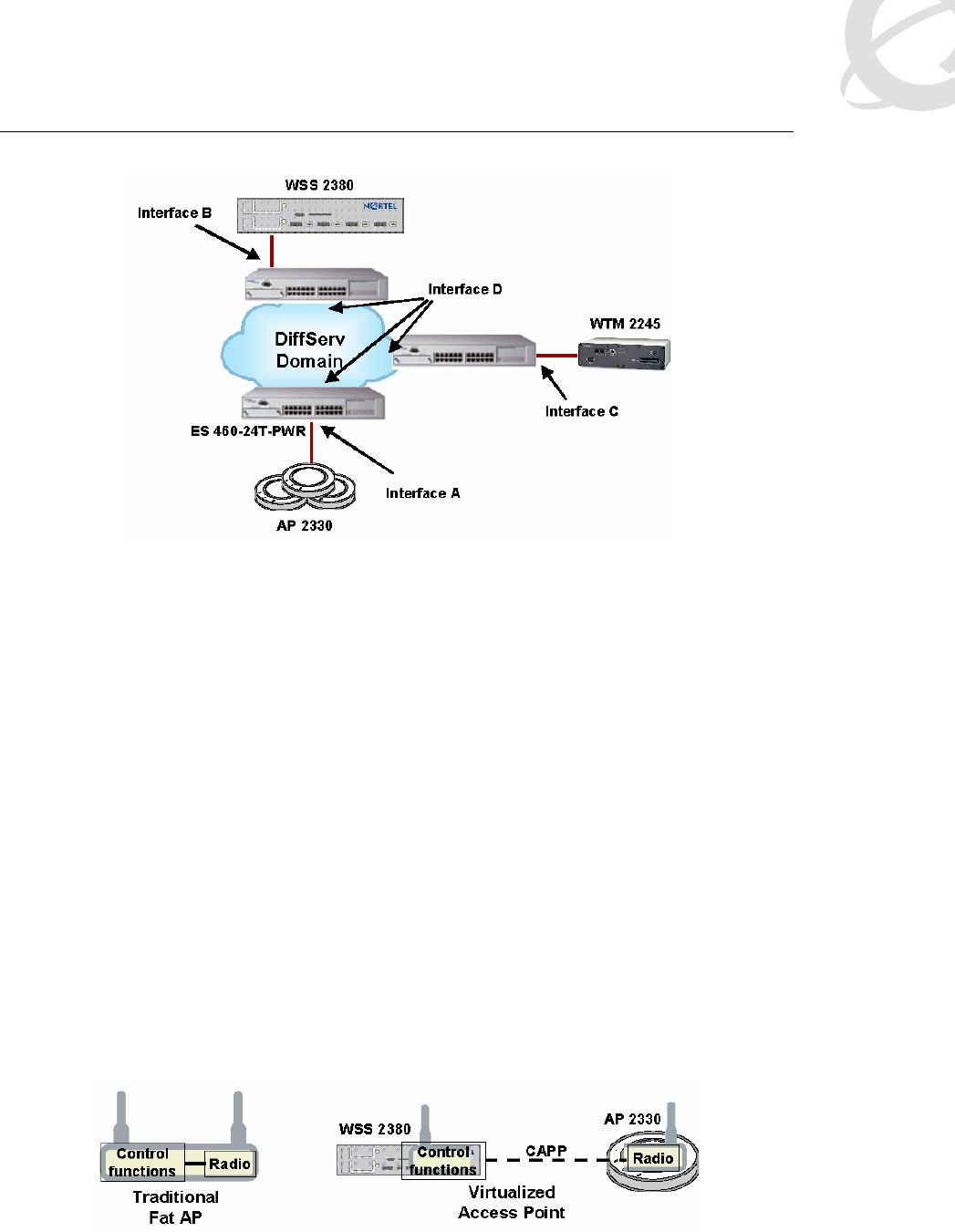
Voice over Wireless LAN Solution Guide v1.0 December 2005
______________________________________________________________________________________________________
Page 41
Figure 14: ES family switches performing packet classification
2.5.2.1 Prioritizing/marking CAPP
There are a number of ways to prioritize Control and Provisioning Protocol (CAPP), one of which
is to key on the system IP address of the WSS 2300. CAPP uses IP protocol 0x04 for transport,
but because the ES family cannot filter on user-defined IP protocol values, this is not a viable filter
criterion. Because CAPP is always an L3 tunnel, you do not have to worry about different modes
of operation. The main issue is distinguishing control, data, and voice within the CAPP tunnel.
The WSS 2300 marks the ToS field and maps that to the outer ToS field of the CAPP tunnel so
classifying traffic that is contained within CAPP is not impossible, though there are a couple of
difficulties: First, control traffic is not marked, even though this is more important than voice.
Second, the ToS field values are a subset of DSCP and the specific default values are different
than with other Nortel products. The AP 2330 also is capable of marking the ToS field of CAPP
tunneled packets when WMM is enabled. In this mode, the AP uses the access category in the
802.11e QoS field to identify the CoS of the packet and mark the ToS field in the IP header
appropriately. When WMM is disabled, the AP does not mark the ToS field. Note that a VoWLAN
solution that includes WLAN Handset 2210/11/12 currently requires WMM to be disabled in the
AP.
Because of the distributed 802.11 MAC across the WSS 2300 and AP 2330, the control traffic
should be considered the highest priority traffic class on the network. The WLAN 2300 series is a
distributed architecture in which the WSS and AP work together to become one virtual access
point. To compare this to a standard AP, CAPP serves a function not unlike a system bus, as
shown in Figure 15. So it is important for the ES to identify and mark control traffic. Fortunately
there is a solution.
Figure 15: Distribution of access point functions

Voice over Wireless LAN Solution Guide v1.0 December 2005
______________________________________________________________________________________________________
Page 42
The basic concept is to have the WSS 2300 classify and mark all data, voice, and video traffic,
with the assumption that the remaining unmarked traffic consists of control traffic. For example,
assume you are using a port-based ACL on the WSS 2300 to examine all ingress traffic on the
network port. This is traffic destined to wireless devices, which will be encapsulated in CAPP and
sent back out the network port to a DAP or to directly connected APs. Voice should be identified
and marked as CoS 6. For the WLAN Handsets 2210/11/12, do this by creating a rule that
matches IP protocol 119 (SVP). All other traffic can be marked to any desirable number as long
as it is not 6, 7, or 0. On the ES family, configure the port connected to the WSS 2300, shown in
Figure 14 as Interface B, as an untrusted port. “DSCP” values (really the ToS bits) that are
premarked by the WSS 2300 and arrive at Interface B, will be maintained upon egress from the
ES, shown as Interface D, into the DiffServ domain. Configure an additional rule for Interface B to
identify all CAPP traffic without a DSCP value and remark it with a DSCP value of 0x30 (110000)
corresponding to the Class Selector 6 (CS6) class. In addition, if CAPP is running on VLAN
tagged trunks at Interface D, you must set the 802.1p value to 7.
The remaining limitation is how to handle CAPP traffic from AP to WSS. The traffic in that
direction at Interface A will be unmarked, because the AP 2330 does not mark or classify packets
when WMM is disabled. For an ES 460-24T-PWR port connected to an AP, it is best to simply
mark all traffic ingressing on that interface with a DSCP value of 0x2e (101110) corresponding to
the expedited forwarding (EF) class.
2.5.2.2 Prioritizing/marking interswitch (WSS 2300) traffic
There are a number of protocol interactions that take place between WSS 2300s in a Mobility
Domain. When a user roams across different WSS 2300s, user information is passed between
the switches. Because this interaction serves a critical function in roaming, and because roaming
latency must be kept to an absolute minimum to maintain call quality, it is desirable to ensure that
this traffic is classified as a Network service class. Because this traffic will enter the DiffServ
domain at Interface B, the ES interface must be configured to identify and mark it as class CS6,
which has a corresponding DSCP value of 0x30. The 802.1p bit (if present) should also be set to
7.
In addition, when subnet roaming, the user traffic may be tunneled back to another WSS 2300
depending on whether the user’s subnet is local or remote. It is recommended that this tunneled
traffic be classified as a Premium service class and marked as class EF. This translates to a
DSCP value of 0x2e and an 802.1p bit value of 6. The easiest way to classify this on the ES
family at Interface B is to use source IP and destination IP address filters that match the IP
addresses of the WSS 2300 switches. The interswitch tunnel utilizes IP Protocol 0x04 for
transport just like CAPP, but this is not a possible filter criterion due to ES filter limitations.
2.5.2.3 Prioritizing/marking SVP
Handset voice traffic from the WSS 2300 to the LAN and from the LAN to the WSS 2300 at
interface B will be encapsulated in SVP. Because SVP contains voice traffic, it is recommended
that it be treated and marked as per the Premium service class. Figure 16 shows the levels of
nesting of voice traffic within SVP and CAPP. As you can see from the diagram, CAPP exists
between WSS 2300 and AP 2330 and traverses interfaces A and B. SVP is encapsulated in
CAPP, and during that leg of the path SVP is invisible to the network. SVP then traverses the
network between WSS 2300 and WTM 2245 between interfaces B and C. Native VoIP traffic is
nested within SVP and is invisible to the network over the CAPP and SVP legs of the path. Native
VoIP traffic only appears at Interface C as it reenters the DiffServ domain.
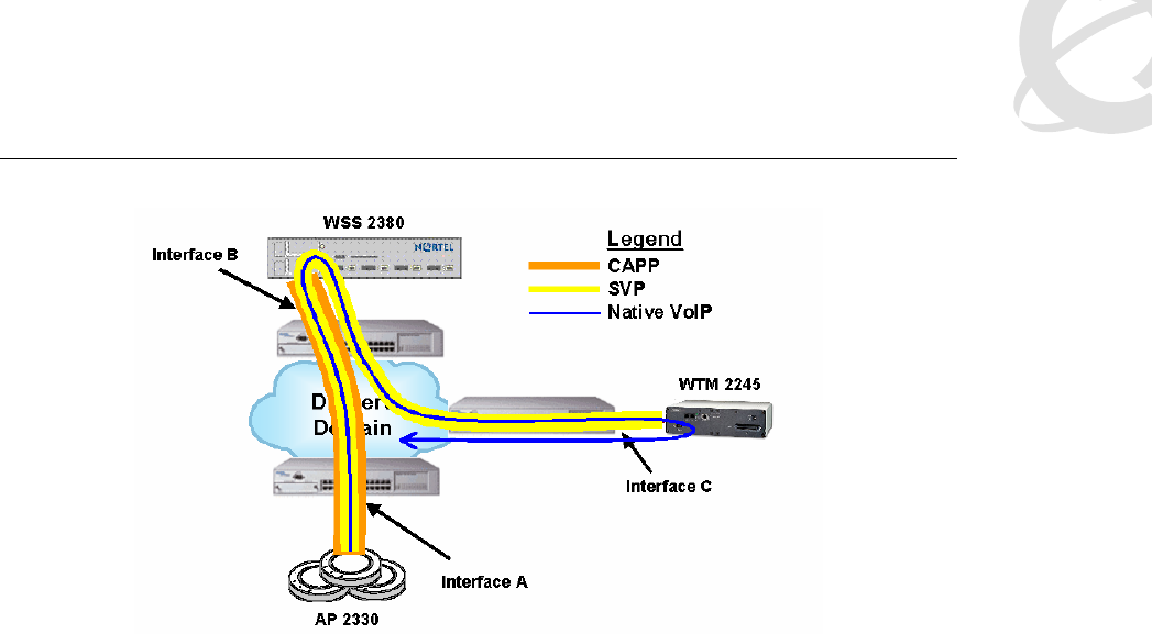
Voice over Wireless LAN Solution Guide v1.0 December 2005
______________________________________________________________________________________________________
Page 43
Figure 16: Nesting of VoIP within SVP and CAPP
The ES at Interface B must implement IP filters in order to classify SVP traffic, albeit indirectly.
There is no way to define a filter to match a user defined IP protocol number (SVP uses IP
protocol 119 or 0x77). This means that you must use an alternative classifying criterion. The
easiest thing to do is to define an IP filter based on source/destination addresses. Configure the
filter at Interface B to match the destination IP address field against the node address of the WTM
2245. This traffic will additionally be marked by the ES as class EF so as to identify it as Premium
class. This means using a DSCP value of 0x2e and 802.1p bit value of 6.
No filtering is needed at Interface C because the WTM 2245 can now mark the DSCP field.
Therefore you can set this interface as a trusted interface, which will also address a portion of the
native VoIP QoS requirements as well. Configure the WTM 2245 to mark traffic with a DSCP
value of 0x2e.
2.5.2.4 Prioritizing/marking native VoIP traffic
Because the call server and other VoIP devices mark their traffic on that end of the call, far-end
QoS marking is not covered in this document. Note, however, that the WLAN Handsets
2210/11/12 do not currently mark the DSCP field on their transmitted packets, so it is necessary
to perform this function elsewhere. The best place is on the WTM 2245 because that addresses
both the SVP encapsulated markings and the native VoIP traffic markings. Packet marking on the
WTM 2245 allows you to configure ES with a trusted port so that the markings are respected with
no need for re-marking.
2.5.3 Ethernet Routing Switch 5510/5520
To keep redundant material to a minimum, the descriptions from the corresponding ES family
sections are not repeated here. Only where the ERS 5510/5520 differs in capabilities or
recommendations from the ES will further discussion be added. An ERS 5510/5520 may be
located at a number of positions in the network with respect to the WLAN products, as shown in
Figure 17.
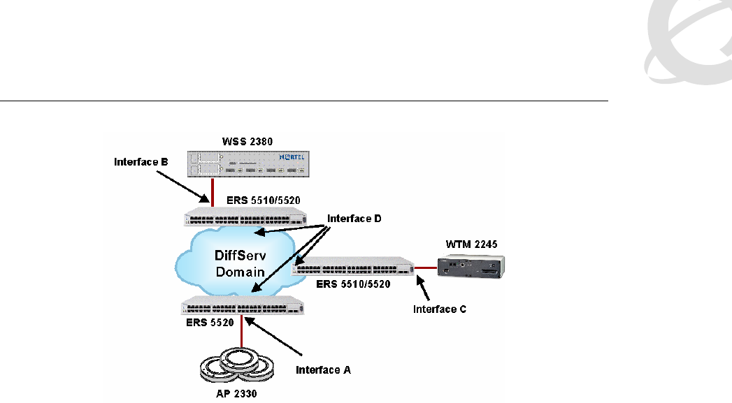
Voice over Wireless LAN Solution Guide v1.0 December 2005
______________________________________________________________________________________________________
Page 44
Figure 17: ERS 5510/5520 performing packet classification
These deployment options are presented strictly for the sake of discussion concerning the
capabilities of the ERS 5510/5520 given possible locations within various networks. Because the
ERS 5520 has PoE ports, and the ERS 5510 does not, only an ERS 5520 can provide Interface A
to AP 2330s. Given a particular real-world network, implement the recommendations below if the
ERS 5510/5520 is directly connected to any of the devices at the specified interfaces.
2.5.3.1 Prioritizing/marking CAPP
For an ERS 5510/5520 connected to a WSS 2300 at Interface B, you can use a prioritization
approach similar to that used for the ES family products. That is specifically to have the WSS
2300 mark all voice and data traffic, leaving only the control traffic unmarked. A filter on the ERS
5510/5520 can be designed to identify all remaining CAPP traffic that has no DSCP marking and
mark it as 0x30 (110000) corresponding to the CS6 class.
Configure an ERS 5520 connected to an AP2330 at Interface A to mark all traffic with DSCP
value of 0x2e (101110) corresponding to the EF class. The easiest way to accomplish this is by
marking all traffic ingressing on the interface.
The ERS 5510/5520 can implement an alternative classification scheme using the offset filtering
capabilities. This feature is particularly useful at Interface A because the AP is not capable of
marking packets when WMM is disabled. An offset filter can be used to identify SVP buried within
the CAPP protocol and mark the outer CAPP packet. You might be able to use similar offset
filters to identify and mark control traffic and other data and multimedia. However, discussion of
the exact offsets and bit patterns to match are beyond the scope of this document.
2.5.3.2 Prioritizing/marking interswitch (WSS 2300) traffic
The classification techniques for an ERS 5510/5520 at Interface B with respect to inter-WSS
traffic do not differ from the ES. The marking behavior should also follow as described for the ES.
2.5.3.3 Prioritizing/marking SVP
The ERS 5510/5520 does not have the same restriction on user-defined IP protocol numbers,
and therefore the recommended filtering criteria at Interface B to identify SVP is to use an IP
classifier that matches IP protocol 119. The ERS 5510/5520 must then mark the DSCP value as
0x2e.
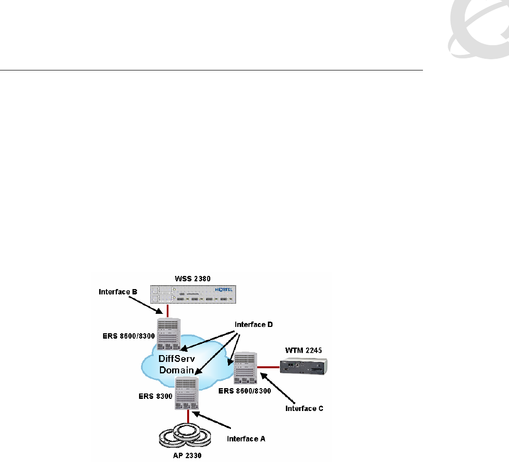
Voice over Wireless LAN Solution Guide v1.0 December 2005
______________________________________________________________________________________________________
Page 45
An ERS 5510/5520 connected to the WTM 2245 at Interface C can be configured to simply trust
the markings set by the WTM 2245. Also, you would set WTM 2245 to mark traffic with a DSCP
value of 0x2e.
2.5.3.4 Prioritizing/marking native VoIP traffic
As noted previously, it is assumed that remote VoIP telephones, call servers, and LAN switching
equipment are properly marking and classifying traffic. Locally, as the VoIP packets leave the
WTM 2245, they will be classified properly if the ERS 5510/5520 is set to trust markings.
2.5.4 Ethernet Routing Switch 8300/8600
To keep redundant material to a minimum, the descriptions from the corresponding ES family
sections will not be repeated. Only where the ERS 8300/8600 differs in capabilities or
recommendations from the ES will further discussion be added. An ERS 8300/8600 may be
located at a number of positions in the network with respect to the WLAN products, as shown in
Figure 18.
Figure 18: ERS 8300/8600 performing packet classification
When another device, such as an ES or ERS 5500 series, is directly connected to one of these
WLAN or VoIP components and the ERS 8300/8600 are core devices in the DiffServ domain, the
ES performs the classification and marking of traffic. If that is the case, then the proper
configuration of an ERS 8300/8600 as a DiffServ core device is to simply respect the PHB
specified by the DSCP value of the packet as marked by the DiffServ edge device. It is assumed,
however, that in the descriptions that follow the ERS 8300/8600 is directly connected to these
WLAN and VoIP devices and cannot rely on packets being premarked. This is strictly for the sake
of discussion concerning the capabilities of the ERS 8300/8600 given possible locations within
various networks. Because the ERS 8300 has PoE ports, and the ERS 8600 does not, only an
ERS 8300 can provide Interface A to AP 2330s. Given a particular real world network, implement
the recommendations below if the ERS 8300/8600 provides any of the shown interfaces to the
WLAN and telephony devices. If the ERS 8300/8600 is a core DiffServ device, implement DSCP-
based filters to respect the markings.
2.5.4.1 Prioritizing/marking CAPP
For an ERS 8300/8600 providing Interface B to a WSS 2300, you can use a prioritization
approach similar to that used for the ES family products. That is specifically to have the WSS
2300 mark all voice and data traffic, leaving only the control traffic unmarked. A DiffServ access
port on the ERS 8600/8300 together with filters can therefore be used to re-mark DSCP values of

Voice over Wireless LAN Solution Guide v1.0 December 2005
______________________________________________________________________________________________________
Page 46
0x00 to 0x30 (110000) corresponding to the CS6 class. All other DSCP/ToS values are left
untouched. Note that this assumes that the WSS 2300 is not connected to the ERS through a
one-arm connection such that CAPP and regular (unencapsulated) user traffic are on the same
port.
An ERS 8300 port connected to an AP2330 at Interface A would be configured to mark all traffic
with DSCP value of 0x2e (101110) corresponding to the EF class. The easiest way to accomplish
this is with a port level QoS setting.
2.5.4.2 Prioritizing/marking interswitch (WSS 2300) traffic
The classification techniques for an ERS 8300/8600 at Interface B do not differ from the ES. The
marking behavior is also as described for the ES.
2.5.4.3 Prioritizing/marking SVP
Because the ERS 8300/8600 has the same restriction on user-defined IP protocol numbers as
the ES family, the recommended filtering criteria at Interface C is the same as for an ES at
Interface C. As in the ES case, the filter on a port connected to a WSS 2300 matches the
destination IP address field against the node address of the WTM 2245 and marks the DSCP
value as 0x2e.
A port connected to the WTM 2245 can be configured to simply trust the markings set by the
WTM 2245.The WTM 2245 should also be set to mark traffic with a DSCP value of 0x2e.
2.5.4.4 Prioritizing/marking native VoIP traffic
As noted previously, it is assumed for purposes of this discussion that remote VoIP telephones,
call servers, and LAN switching equipment are properly marking and classifying traffic. Locally as
the VoIP packets leave the WTM 2245, they will be classified properly if the ERS 8300/8600 is
set to trust markings.
2.5.5 QoS summary
Regardless of the switch model at any of the interfaces described in this section, there are many
general requirements that can be summarized on a per-interface basis. At Interface A, the main
need is to prioritize CAPP. Interface B needs to prioritize CAPP as well as interswitch
authentication and roaming traffic. Lastly, Interface C will be forwarding both native voice and
SVP, though you should implement Interface C as a trusted port because the WTM 2245 can
mark its own traffic.
2.6 WLAN Handset 2210/11/12, IP Softphone 2050, MVC
2050, and MCS Client support on the same network
It is a relatively easy task to design a WLAN and LAN for one type of VoWLAN device, such as
WLAN Handsets 2210/11/12. However, many customers may want a comprehensive VoWLAN
implementation, including soft phones on PCs and PDAs in addition to dedicated handset
devices. Designing a network to adequately support all types simultaneously is much more
challenging because of the different QoS implementations and auxiliary devices used.
2.6.1 Issues
Most of these challenges relate to the fact that the soft clients do not use SVP while the handsets
do. Having two different QoS solutions implemented side by side creates a number of problems
that must be resolved. Note that there is currently no perfect solution that does not require
compromise in some key areas. You may need to make difficult decisions in order to support both

Voice over Wireless LAN Solution Guide v1.0 December 2005
______________________________________________________________________________________________________
Page 47
types of devices side by side. The other major source of problems relates to security capabilities
among clients.
2.6.1.1 Separating data and voice applications
In addition to having different QoS features, PDAs and PCs present another unique challenge
that handsets do not have to deal with, namely supporting data and voice on the same device.
The WSS 2300 has the ability to prioritize on a per-packet basis through ACLs, which significantly
helps to enable a converged WLAN. So in the downstream direction (from WSS to AP), the WSS
can support multiple applications to a single device over the same radios. The upstream direction
still has many client and application dependencies. Ultimately WMM and 802.11e are keys to
building upstream QoS for a mix of applications on the same device, but the applications
themselves must be designed to make use of the separate access classes. In essence this issue
is half resolved today by the WLAN 2300 Series. The remaining issues reside with the client and
applications.
2.6.1.2 Admission control
The WTM 2245 is currently the only device in the solution capable of admission control in terms
of call capacity. Yet it only accounts for calls placed from WLAN Handsets 2210/11/12, not from
IP Softphone 2050, MVC 2050, or MCS Client devices. Therefore, having a mix of WLAN
Handsets 2210/11/12 and PC/PDA voice applications on the same WLAN completely
compromises the entire admission control capability due to the fact that only some calls are
counted. For example, suppose you have the WTM 2245 set to allow only up to six calls per AP
because you want to allow room for a couple of PDA calls. If there are no PDA calls active, then
you are wasting capacity that handsets could otherwise be using. On the other hand, you can still
have too many PDA calls active on an AP and impact your handset calls. So there is no true
protection in this environment. The only way to handle this situation is to revise the number of
handset calls per AP to a low enough number to safely accommodate a certain number of PDA
calls per AP. This problem is more likely to occur between handsets and PDAs, but can also
happen with PCs with a soft client. The reason is that PDAs generally are 802.11b-only devices
today and thus they must share the same radio spectrum with handsets. PCs may have 802.11b
only or 802.11g NIC and in such cases they compete for the radio frequency as well. But PCs
might also have an 802.11a NIC, in which case you could allow only PCs to use the 802.11a
radio, thus mitigating the mixed admissions control issue described here. In summary, PCs have
enough flexibility for the design phase to resolve the issue of compromised admission control of
handsets and WTM 2245, but PDAs do not (today).
2.6.1.3 Prioritization
It was previously discussed that queuing behavior depends on the WMM setting and that ACLs
are used to mark the priority of packets. Also when WMM is disabled (a requirement to support
WLAN Handsets 2210/11/12), packets identified as CoS 6 or 7 are put in the SVP queue, which
implements zero backoff. If non-handset voice is added, you must decide whether to leave other
voice traffic at a lower priority or to put it in the SVP queue where zero backoff is implemented.
The answer to this question partly depends on the radio being used by this other voice traffic. For
example, PCs may be using an 802.11a radio with WMM enabled. In this case, such traffic is not
put in an SVP queue. Another example is a PDA using an 802.11b radio. In this case, handset
and PDA voice calls are shared on the same radio.
2.6.1.4 Security
Another common issue is the lack of consistent security feature support across varieties of
devices. Handsets are the most limited in terms of security options, and laptops generally have
the most options. The situation is a lot better now that the WLAN Handsets 2210/11/12 support
WPA-PSK and WPA2-PSK. In most cases, a common encryption scheme can be selected that
meets the security requirements of the network. If the data network will use WPA2 for encryption,

Voice over Wireless LAN Solution Guide v1.0 December 2005
______________________________________________________________________________________________________
Page 48
the WLAN Handset 2210/11/12 can implement it as well. However, the authentication mechanism
may still be a problem if you desire 802.1x.
The WLAN 2300 series can support mixed authentication types on the same SSID for such single
SSID scenarios, but the truth is that authentication security is only as strong as the least of the
authentication types. For example, if MAC authentication is mixed with 802.1x, then you can only
trust devices to the degree that you can trust MAC authentication. But if MAC authenticated
devices are put in a separate VLAN with ACLs locking down access to only certain telephony
devices, it is no less secure than implementing a separate SSID for MAC authentication. So the
converged SSID is not as insecure as it seems at first glance.
2.6.2 Recommendations
Because of problems detailed above, Nortel recommends the following for multiple VoWLAN
product deployments.
First, determine whether multiple SSIDs are needed for different voice and/or data
devices. Security options or lack of common security features may indicate multiple
SSIDs. The need for different fall-through options might also indicate multiple SSIDs.
Regardless of what you choose, many of the remaining decisions are the same.
Wherever possible, use Softphone or MCS client voice over 802.11a to minimize
contention for 802.11b resources and to mitigate the lack of consistent admission control.
WMM can be implemented on the 802.11a radio if desired, but not the 802.11b radio.
Implement ACLs to classify and mark all voice traffic, regardless of whether from a
handset or a soft client. All voice traffic should receive the same level of marking,
meaning CoS 6 or 7.
Configure the WTM 2245 with reduced call numbers per AP to allow some room for calls
from PDAs on APs.
There are other possible variations of the multiple voice client type theme. These
recommendations are not meant to be exclusive of other viable possibilities. Rather this
discussion is meant to help you think through the issues by way of example and basic
recommendations. For example, if you have all PCs confined to the 802.11a radio only, and all
PDAs and handsets confined to the 802.11b radio, it is conceivable to have handsets mapped to
CoS 6 or 7, PDAs also mapped to CoS 6 or 7, voice enabled PCs mapped to CoS 6 or 7 on the
a-radio, and data only PCs mapped to CoS 2 or 3. High priority packets on the two different
radios do not compete because they use different radio resources.
3. Infrastructure support
While other infrastructure components are not part of the core solution, their absence can make a
deployment a practical impossibility or their presence a time saving and manageability
enhancement.
3.1 Network management
Network management is as much strategy and process as it is
applications. The individual applications and capabilities are
discussed following the management framework. Managing a
converged network consists of four key phases:

Voice over Wireless LAN Solution Guide v1.0 December 2005
______________________________________________________________________________________________________
Page 49
1. Assessment – Network Health Checks and WLAN Site Surveys (post-deployment) are
critical assessment items. The main goal is to verify the network’s ability to provide voice
at the required QoE (Quality of Experience).
2. Predeployment – Prior to deploying VoIP handsets, the network is made ready through
the rollout of QoS across the network. Note that this phase assumes the WLAN itself is
already deployed.
3. Ongoing Monitoring – Keeping tabs on the performance of the converged network is
crucial to ensuring that voice quality continues to meet expectations as the network
grows and evolves over time.
4. Reporting and Planning – Keeping track of exceptions and problems and forming plans to
resolve issues is the last step. It is also the beginning, in the sense that resolution of
problems takes you back through the assessment, predeployment (QoS configuration),
and monitoring phases again.
Nortel ties this business cycle together seamlessly with a set of products that provide a
comprehensive solution, comprised of integrated, innovative standards-based technologies such
as RTCP-XR for detailed real-time management of calls in progress. The overall solution is
referred to as Proactive Voice Quality Management (PVQM). Carefully note that the four phases
are part of a cyclical process. Periodic assessments are part of the maintenance plan for
convergence. Each of these phases is addressed by specific components in the management
portfolio and provides the context for more detailed descriptions. Some management
applications, such as certain element managers, do not fit as cleanly into the framework, either
crossing multiple phases or providing incomplete functionality, and will be addressed as
exceptions.
3.1.1 Assessment
WMS 2300 planning
The WMS 2300 has a network planning capability, which includes an ability to predict the best AP
locations based on building attenuation characteristics. You can import AutoCAD, GIF, or JPEG
drawings of the floor plans in a building and create a 3-D model of the facility. You can define the
RF characteristics of walls, floors, and other obstacles to build a detailed RF map. The WMS
uses this map along with other information about the number of users and throughput
expectations to simulate a site survey of the facility and plot the locations of APs.
This planning tool is very useful in the early stages of a WLAN network deployment, because it
accelerates many of the early stages of a site survey and can potentially eliminate certain other
tasks related to the site survey process. For example, the typical initial site visit can be truncated
to a walk-around inspection for things that typically pose problems with RF, like a row of filing
cabinets along a wall. The planning tool now removes much of the initial guesswork about AP
locations that was done manually by hand and compass. The tool may, in some circumstances,
let you skip the predeployment site survey process (assuming that you will perform a
postdeployment survey), in which you use tripods with APs and a laptop to manually measure the
RF characteristics of an area.
However, the planning tool is not a substitute for the postdeployment site survey. Some people
might be tempted to use the planning tool to predict coverage and simply deploy the network as
shown with no other validation steps. Nortel does not recommend this use of the tool, and in fact
does not support it when voice is deployed over the WLAN. The tool is supported for simplifying
the planning, deployment, and site survey phases, and for streamlining and reducing many of
these processes. In addition, the WMS 2300 and the plan built with the planning tool carry
forward into the postdeployment and monitoring phases, resulting in further efficiencies.
Specifically, the same map that you use to predict optimal AP locations is later used to show the
location of rogue devices and clients.

Voice over Wireless LAN Solution Guide v1.0 December 2005
______________________________________________________________________________________________________
Page 50
WLAN Site Survey
Technical support for VoWLAN is contingent on customers performing a prior site survey of the
WLAN. Currently Nortel recommends the use of the Ekahau Site Survey tool to verify the network
deployment, though other site survey tools are acceptable as well. The Ekahau product runs on a
PC and uses your WLAN NIC to collect data for analysis. The output of the tool is a number of
robust visualizations of the network. Aside from verifying the basic coverage of the network, the
software provides a number of visualizations that are particularly useful to VoWLAN deployments.
Perform capacity planning using the data rate analysis view, which shows a color coded view of
the maximum data rate across all APs in the network. With this view, you can see where your
handsets will be able to utilize the 11 Mbps data rate as opposed to rate scaling down to lower
rates. As discussed earlier, planning based on data rate can have a big impact on voice call
capacity planning.
Predict AP selection and roaming using the strongest AP view. This view shows the AP with the
strongest signal for each location in the building, using color codes for each AP. This allows you
to predict the APs that will be the primary choice of voice devices to use given their location and
allows you to predict where the handoff to another AP (and which AP) will likely occur given a
moving user.
Perform resiliency planning through the AP reachability view. This view presents a color coded
visualization of the number of reachable APs from each point in the network. Locations where the
tool detects one AP, locations where the tool detects two APs, locations where the tool detects
three APs, and so on, are marked in distinct colors. With this visualization, you can see where the
network is vulnerable to a single point of failure. It is preferable to have at least two APs that are
capable of offering coverage to every point in your building. Note that if the APs are AP 2330s
and the WSS 2300 is using auto-tune power, the resiliency is in the power adjustment, meaning
that the site survey may show only one AP reachable from a given point. In reality, the hole
covering capability of the WSS 2300 may be able to cover the location with two APs though
current power levels do not indicate this. To plan for resiliency, turn off auto-tune power in order
to see what the true potential coverage is in the event of AP failure.
You can also use the AP reachability view to perform location service planning. A minimum of
three APs must be reachable for triangulation to be effective. So use the AP reachability feature
to verify a consistent 3+ AP coverage across the building. Location capabilities have a number of
client dependencies, so verifying triangulation coverage is more complex than it appears. There
are two main location solution types: those that use the client to collect information about the APs
in the network (client-based location), and those that use the APs to collect information about the
client (network-based location). Both use a form of triangulation to compute the location of the
device. Depending on the power level of an AP, it may be able to hear devices it cannot transmit
to. These factors combined create the following two scenarios. 1) It is hard to calibrate network-
based solutions using a laptop running the site survey because APs may be able to hear clients
that cannot hear the AP. If AP transmission power levels are not at a maximum, then they will be
able to hear clients over a farther distance than its own transmissions will travel. This can cause
the site survey application to underestimate the number of APs that can participate in
triangulation. 2) Client-based solutions cannot triangulate APs that are not detectable because
their power is lower. But the site survey application will accurately reflect the number of APs that
can be used for triangulation.
What this means is that to plan triangulation for network-based solutions, turn off auto-tune power
to more accurately reflect the range of the APs. Yet to verify the triangulation coverage of client-
based solutions, you must turn on auto-tune power if auto-tune power is enabled in the normal
running state of the network.

Voice over Wireless LAN Solution Guide v1.0 December 2005
______________________________________________________________________________________________________
Page 51
NetIQ Vivinet Assessor
Performing a Network Health Check is probably the most critical step to ensuring a smooth rollout
for any VoIP deployment. This applies even more so to VoWLAN, because a WLAN is a more
challenging QoS environment than modern wired networks.
The NetIQ Vivinet Assessor 3.0 or later is the tool of choice for Network Health Checking.
(Previously NetIQ Chariot, now an Ixia product, was recommended for Network Health Checking.)
This product uses a standard PC (preferred for wired testing) or laptop (for WLAN testing for
WLAN mobility) as a voice traffic generation and analysis tool. Several nodes can be set up in
various parts of the network to simulate calls to and from those areas. Each node simulates call
volumes through traffic generation so that you can stress test access links, backbones, and WAN
links as necessary. You can also configure codecs and packetization rates and other factors to
closely mimic the future VoIP environment.
Vivinet Assessor performs a comprehensive analysis of the simulated traffic, including reports on
delay, jitter, and packet loss. The R values or Mean Opinion Score (MOS) are reported for these
simulated traffic loads in order to provide a baseline for performance expectations. These
analyses are also used for capacity planning because they show the capacity at which the Quality
of Experience (QoE) ratings start falling. More importantly, the process of analyzing the network
reveals many latent network problems that would otherwise remain undetected until deployment.
For example, duplex mismatches may exist in various locations of the network, and data
applications, being very tolerant to packet loss, typically do not reveal the problem unless it is
severe. The issue is immediately noticeable when a voice call traverses such a link. Vivinet
Assessor is extremely useful for identifying symptoms of issues and fixing such problem areas in
the network long before the customer places the first call.
3.1.2 Predeployment
Enterprise Policy Manager (EPM)
Section 2.5, “QoS,” discussed the ports and protocols used in various parts of the VoWLAN
architecture. It also discussed how the wired infrastructure might be configured to guarantee end-
to-end QoS through classification and marking of traffic. Managing the QoS configuration and
security filters of network elements is the role of Enterprise Policy Manager (EPM). It features
one-click QoS provisioning for voice, video, and data over IP.
EPM is capable of configuring the ES and ERS products discussed in section 2.5 as well as most
other Nortel products. As of today, however, EPM does not configure the QoS of the WSS 2300
or AP 2330.
WMS 2300
In order to easily manage the QoS configuration of the WLAN products, use the WLAN
Management System (WMS). This product is the element manager system for the WLAN 2300
Series products and also serves as a stand-alone Network Management System (NMS) platform
for the same products (currently support for the WLAN 2300 series is not built into Enterprise
NMS). WMS supports policy-based configuration of multiple WSS 2300s and AP 2330s. For
example, you can configure the ACLs used for QoS classification as part of a general WSS 2300
policy, and have them automatically applied to all switches and even to particular switch ports, if
desired.
3.1.3 Monitoring and reporting
Enterprise NMS (ENMS)
Enterprise NMS (ENMS) is a cross-portfolio management platform for fault management, network
visualization, and troubleshooting. It can receive traps and statistics from the CS 1000 or
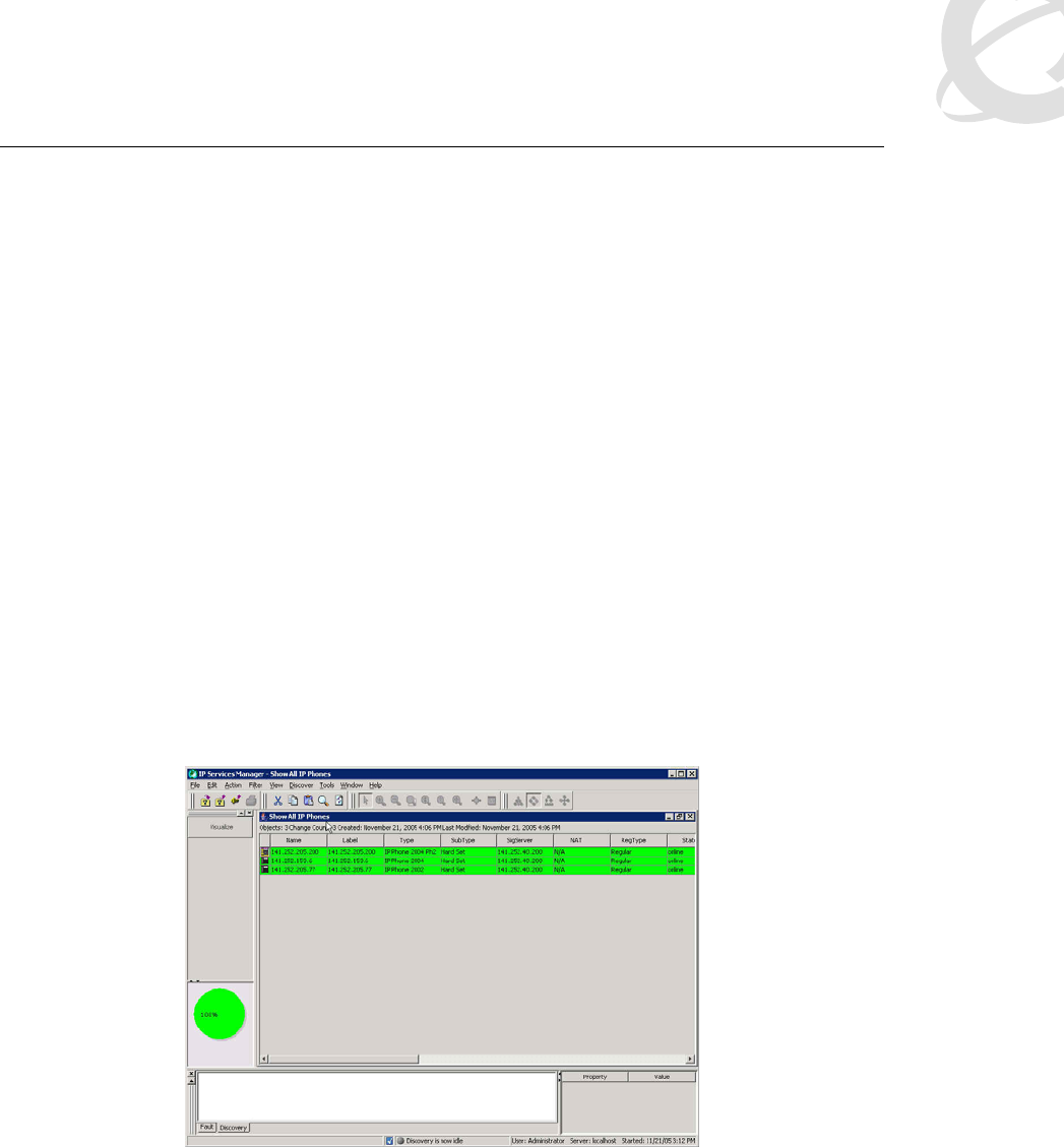
Voice over Wireless LAN Solution Guide v1.0 December 2005
______________________________________________________________________________________________________
Page 52
Meridian 1 products (as well as virtually all other Nortel products). It can discover the call server
equipment that it supports, it can display the information for the slot or port that the call server
components are attached to, and it can discover the TLAN and ELAN on a CS 1000 Signaling
server. It differs from Communication Server 1000 Telephony Manager in that ENMS is a
comprehensive monitoring platform for virtually all Nortel products, while Communication Server
1000 Telephony Manager supports only VoIP products and features. ENMS is the product that
ties all the other management packages together. Communication Server 1000 Telephony
Manager has more capabilities in terms of element configuration and data analysis (for voice
products) than ENMS.
Enterprise Network Management System 10.4 makes convergence management a quick and
easy reality with the Converged View in the new IP Service Management (IPSM) display. The
IPSM display provides a business-oriented overview of the Convergence Service. With IPSM, an
operator can see the status of overall service level that is being provided at a glance, and easily
zoom in with detailed troubleshooting tools if a problem is indicated. If a phone is unreachable, or
if there is a degradation of quality in a call, it is indicated in the IPSM tabular view. The call quality
alert shows the near-end and far-end IP address and Terminal Number (TN).
Figure 19 shows the IPSM overview with a list of the phones that are registered to a particular CS
1000 system. Many details, including type of phone (hard phone/soft phone, such as the IP
Softphone 2050, which has applicability to VoWLAN), firmware revision, IP address, set TN,
registered TN, source and destination IP port, and so on, are displayed. Phones or components
of the CS 1000 system change color to indicate status. The pie chart in the lower left corner of the
display is updated to show overall status and quality of the phones and CS 1000 systems in the
display.
Figure 19: ENMS 10.4 IPSM overview
When you click on a specific IP Softphone 2050 of interest, the panel in the lower right portion of
the screen displays details automatically, such as the CS 1000 system that the IP Softphone
2050 is registered with. You can then right-click on the phone to show a data network path trace
graphically. For troubleshooting purposes, you can view a path trace to the signaling server or
any other IP address.
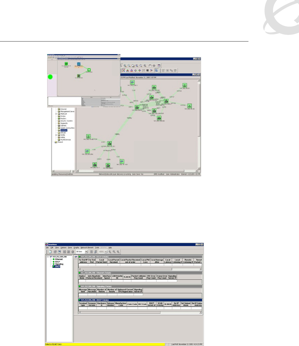
Voice over Wireless LAN Solution Guide v1.0 December 2005
______________________________________________________________________________________________________
Page 53
Figure 20: ENMS 10.4 IPSM convergence view
ENMS can provide down to physical slot port connectivity for the wired network. This topology
data is extremely useful when shown in the Converged View of a Path Trace. You can set the
display to refresh periodically to display the latest information about where an IP Softphone 2050
user is roaming and their IP address changes.
With RTCP-XR, such as that which is built into the latest version of the IP Softphone 2050, it is
possible to right-click on the set in the IPSM Convergence or tabular view and retrieve detailed
real-time set statistics, such as local and remote latency and jitter.
Figure 21: ENMS 10.4 IPSM detailed RTCP-XR statistics
The IPSM view in Enterprise Network Management System 10.4 provides the most benefit if you
use it in a network with both Nortel voice and data equipment. NetIQ AppManager is a Nortel
Strategic Alliance Partner product, currently available on the Nortel Pricelist, that you can use to
provide full PVQM (Proactive Voice Quality Management) features where the data network is
heterogeneous. Currently, ENMS is designed to be a real-time monitoring system, whereas NetIQ
AppManager can provide longer term Service Level Agreement (SLA) reporting.

Voice over Wireless LAN Solution Guide v1.0 December 2005
______________________________________________________________________________________________________
Page 54
Communication Server 1000 Telephony Manager
Communication Server 1000 Telephony Manager is an element manager for the CS 1000 and
Meridian 1 call server/PBX products, as well as a platform for receiving traps and collecting call
statistics and other performance-related data. Call and performance statistics are collected from
the Meridian 1 or CS 1000 and stored on the Communication Server 1000 Telephony Manager
server and can be displayed in a number of graphical reporting views, many of which are
predefined for ease of use. These features allow the Communication Server 1000 Telephony
Manager server to act in a basic performance management role for voice (this is not the same
thing as Proactive Voice Quality Monitoring) within the management framework.
Call tracking is another feature not specifically related to QoS monitoring or fault monitoring, but
important to solution manageability. With this feature, you can track calls fitting defined profiles
and collect data for later trend analysis. You can monitor individual extensions in real time. Also
you can have alarm notifications sent to pagers or workstations for calls that fit specified profiles.
Communication Server 1000 Telephony Manager can perform some alarm management
functions and is a trap receiver for the voice products it supports. It polls call servers, through
SNMP, for additional alarms that are not sent as traps. Alarms can be received from Meridian, CS
1000, IP Line and Trunk, CallPilot, Contact Center Manager Server (CCMS), and Meridian Mail.
Communication Server 1000 Telephony Manager can display fault information locally and also
send the traps on to Enterprise NMS (ENMS), Vivinet Manager, or other management platforms.
NetIQ Vivinet Assessor, Vivinet AppManager, and Vivinet Diagnostics
Vivinet Assessor is used for Network Health Checks and diagnosis. The software also has a
number of features for ongoing monitoring and reporting of issues. Performance Endpoint agents
can be installed on laptops with WLAN interfaces to monitor the performance and quality of the
WLAN. This data is sent to the Vivinet Manager for reporting and analysis. You can configure the
agents with a schedule for generating VoIP traffic in order to periodically run spot checks on the
network’s ability to support VoIP at required quality levels.
Vivinet AppManager is a separately purchased product that you can use in conjunction with
Vivinet Diagnostics to provide detailed service level monitoring, reporting and troubleshooting in a
heterogeneous network environment.
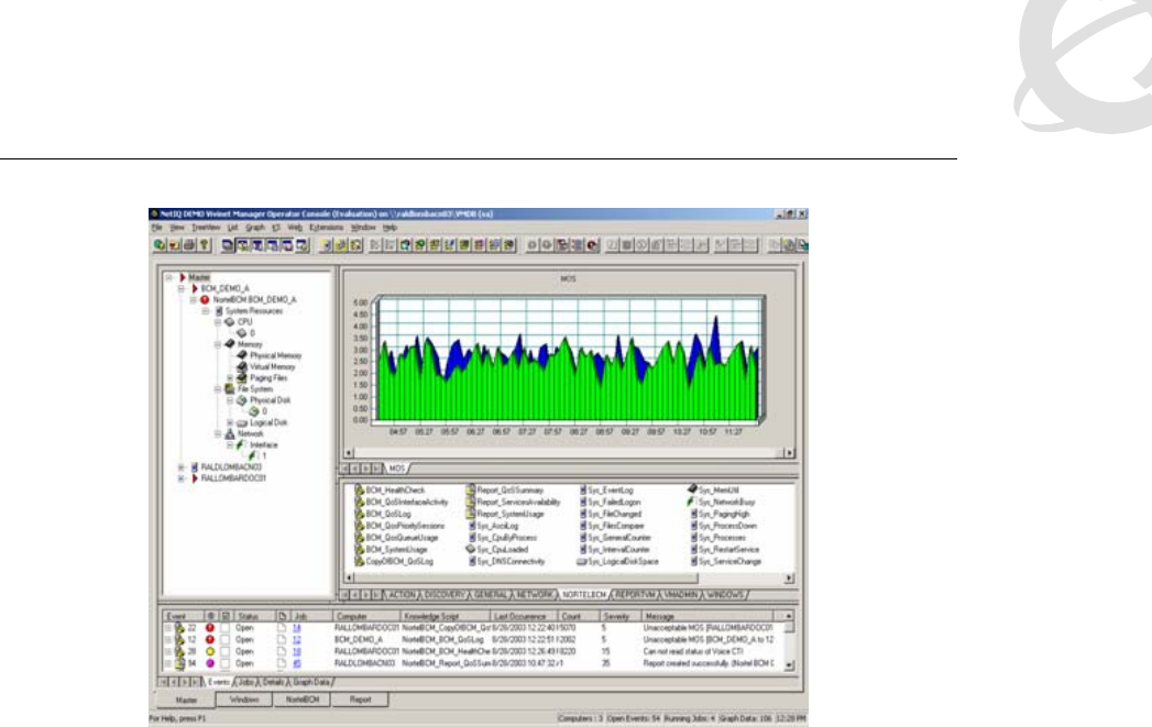
Voice over Wireless LAN Solution Guide v1.0 December 2005
______________________________________________________________________________________________________
Page 55
Figure 22: NetIQ Vivinet AppManager – SLA reporting
For the CS 1000, Vivnet AppManager provides information about the percentage of devices
available versus unavailable, health of interfaces, Voice Call Quality and QoS for Signaling
Server, and Voice Gateway Media Cards (VGMC). AppManager also provides summary analysis
for data loss, jitter, latency, and R-Value.
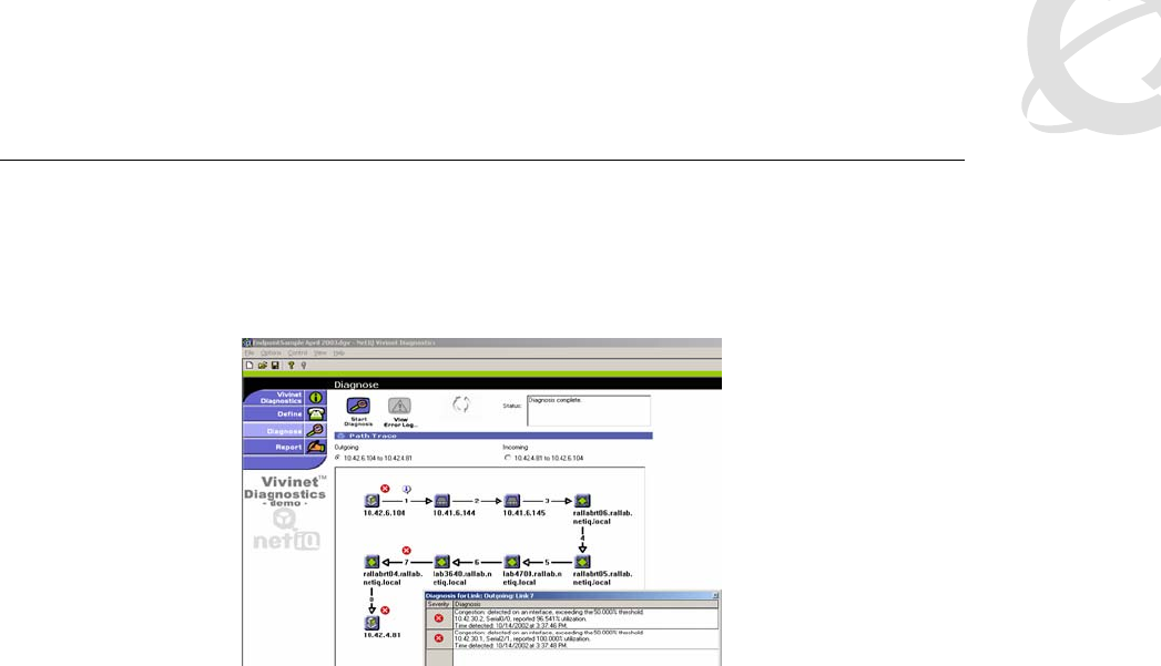
Voice over Wireless LAN Solution Guide v1.0 December 2005
______________________________________________________________________________________________________
Page 56
Vivinet Diagnostics is a product that can be purchased separately and used in conjunction with
Vivinet AppManager. When Vivinet AppManager receives a call quality alert from a Nortel voice
system such as a CS 1000 or BCM for a call in progress, AppManager generates an alert.
Figure 23: NetIQ Vivinet Diagnostics
The alert from Vivinet AppManager activates Vivinet Diagnostics, which traces the path of the
call, collects diagnostic information and can perform root cause analysis and save results for
further analysis and action.
WMS 2300
The WMS is useful for monitoring the physical layer of the WLAN network for problems that
ultimately impact voice quality. The WMS is the trap receiver for all WLAN 2300 series products.
Data collected from periodic polling of the WSS 2300 can be shown in graph format.
Another critical feature of the WMS is the ability to locate and track users within the building.
Without this ability, troubleshooting a poor voice quality report from a user becomes much more
difficult. Knowing where the user is allows you to correlate the issue the user is reporting with the
latest site survey data for that area of the building. The basic mechanism for client location is to
identify the current AP and measure signal strength received in order to plot a graph around the
current AP.
3.1.4 Element management
Communication Server 1000 Telephony Manager
Voice devices, from stations to communication servers, are configured from the Communication
Server 1000 Telephony Manager server, including CS 1000 and Meridian 1 products. Station
administration can also be done through Communication Server 1000 Telephony Manager. It
does have bulk configuration capabilities, but ultimately Communication Server 1000 Telephony
Manager best serves smaller to medium size environments. For larger VoIP installations,
Enterprise Subscriber Manager is a more scalable set management platform. Note that the actual
configuration of the WLAN Handset 2210/11/12 is done manually or through the DHCP server,
while the call server aspects of the handset (TN, DN, and so on) are configured on the CS 1000
or Meridian1, preferably through Communication Server 1000 Telephony Manager.

Voice over Wireless LAN Solution Guide v1.0 December 2005
______________________________________________________________________________________________________
Page 57
Enterprise Switch Manager (ESM)
Just like Communication Server 1000 Telephony Manager is the main element manager for voice
products, Enterprise Switch Manager (ESM) is the main element manager for Nortel wired EDN
switching products. Products such as ES and ERS switches are managed, monitored, and
configured through ESM. ESM makes simultaneous VLAN configuration across multiple devices
quick and easy. It manages software upgrades, performs mass configuration backups, and
performs mass configuration changes.
WMS 2300
The WMS server currently handles all management functions with regard to the WLAN 2300
series products, from planning to configuration to trap reception to device monitoring. With
respect to configuration, the WMS provides bulk configuration capabilities through policies. Most
configuration tasks are easier to perform from the WMS than on a per-switch basis. You can
manage configurations through the automatic auditing process, in which the WMS and WSS
2300s compare configurations. If the two are out of sync, an alarm is raised, and an administrator
can then determine the correct configuration and reconcile in either direction as appropriate. The
WMS also flags problems with WSS 2300 configurations and provides single-click resolution to
those problems.
3.2 DHCP server
Employing a DHCP server can make many aspects of the VoWLAN solution much easier to
operate. In some cases the DHCP server may be a practical requirement. You can also employ
many extensions to streamline other operations. This section discusses most of these.
3.2.1 WLAN AP 2330
The AP 2330 requires a DHCP server only if the AP is going to operate as a DAP. Directly
connected APs do not need DHCP. If there are routers between the AP and WSS 2300, you can
also use the DHCP server to assign WSS 2300 addresses or hostnames through DHCP
extensions. After the AP 2230 has connected to a WSS 2300, it learns from the WSS 2300 the
addresses of the other WSS 2300s in the Mobility Domain, particularly the one that has the high
bias toward that AP.
The DHCP server needs to return either the IP address or a hostname to the AP in DHCP option
43. The exact format is very important. When you configure DHCP option 43 on a Microsoft
DHCP server, the server populates the beginning of the string with a 00x0 (hexadecimal) by
default. This value will cause problems if you do not delete it before typing the proper string.
Specifically, the syntax for an IP address looks like this:
ip:<ip address>
For two or more addresses, it will look like this:
ip:<first ip address>,<second ip address>,<third ip address>, …
Nortel recommends using two or more IP addresses in DHCP option 43 for redundancy
purposes.
The DHCP server can also return a hostname of a WSS 2300 in option 43, in which case the AP
will then use DNS to resolve the hostname to an IP address. If you are configuring the DHCP
server to return a hostname, the need to delete the prepopulated 00x0 (hex) character also
applies. The syntax for a hostname looks like this:
host:<hostname1>,<hostname2>, …
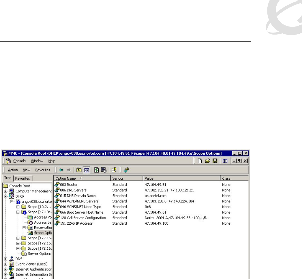
Voice over Wireless LAN Solution Guide v1.0 December 2005
______________________________________________________________________________________________________
Page 58
3.2.2 WLAN Handset 2210/11/12
The WLAN Handset 2210/11/12 also supports numerous DHCP extensions for assigning various
configuration options. Like the AP 2330, the WLAN Handset 2210/11/12 supplies a vendor class
string, which in this case is Nortel-221x-A. Unlike the AP 2330, the WLAN Handset 2210/11/12
does not accept these options from the DHCP server encapsulated in a 43 Vendor Type option
(which is the normal way vendor classes work). Consequently, you do not define these options as
part of a vendor class on the DHCP server. Instead you define them as simply new options that
are assigned using the native code numbers that you give them. The WLAN Handset 2210/11 will
also specifically request a list of options in the DISCOVER message. The list of options (aside
from the IP address, subnet mask, and so on) needed by a WLAN Handset 2210/11 are as
follows: (66) TFTP Server, (128) Signaling Server Address and other parameters, (151) WTM
2245 Address, (152) WAG 2246 Address. Refer to Figure 24 for an example DHCP reservation
for a particular handset.
Figure 24: Assigning parameters to a WLAN Handset 2210/11/12
Another use for a DHCP server is to make code upgrades to the handset easier. If the handset
has an address for a Trivial File Transfer Protocol (TFTP) server configured or assigned by
DHCP, it will not finish booting if the TFTP server is not present. So after the initial code upgrade,
the solution will be more robust if the handset does not look for a TFTP server upon boot up. You
accomplish this by assigning the special value of 255.255.255.255 for the TFTP server address.
This address causes the handset to no longer check for code upgrades. At a later time, when
new code is available, you can set up the TFTP server, and the DHCP server can assign the
proper TFTP server address to handsets, which will then download the code. After the upgrade is
complete, you can set the DHCP server to assign 255.255.255.255 once again as the TFTP
server address.
One last problem deserves mention. Suppose, for example, the company employing this handset
solution is a retailer with many stores. Also suppose that each store has a local call server for the
local employees who use various VoIP devices, so all the attributes are defined at the scope
level. What happens if a supervisor who travels from store to store wants to use their WLAN
Handset 2210/11/12 at each one? The supervisor would get assigned, potentially, to a signaling
server that does not recognize their phone. The best way to support this user is to create a
unique reservation in each remote scope for that user’s WLAN Handset 2210/11/12 and specify

Voice over Wireless LAN Solution Guide v1.0 December 2005
______________________________________________________________________________________________________
Page 59
the proper signaling server. This can of course get cumbersome if there are a large number of
users who travel.
3.3 DNS server
Another way that a DAP that is separated from a WSS 2300 by a router can find a WSS 2300 is
DNS. If the DAP does not receive a DHCP option 43 containing the IP address of a WSS 2300,
then the AP will attempt to resolve through DNS the hostname wlan-switch.domain.com, where
domain.com is the option 15 string provided by the DHCP server. So the DHCP server provides
the domain name and wlan-switch is appended to the domain name.
As mentioned previously, DHCP can return a hostname, in which case the AP will attempt to
resolve the specified hostname.domain.com through DNS. The returned IP address will
correspond with a WSS 2300 so that the AP can learn the IP address of its proper WSS 2300.
3.4 TFTP server
Each WLAN Handset 2210/11/12 and WTM 2245 installation requires a TFTP server. It is used to
provide updated firmware and configuration files to the handsets and WTM 2245. You only need
one TFTP server in the network, and it does not have to be collocated with handsets or WTM
2245. Some of the tested TFTP servers include:
3COM TFTP
TFTP32
PumpKIN TFTP
SolarWinds TFTP
TFTPD32
Note that there is a client-dependent aspect to how the handsets function with the TFTP server.
This means that how well a server works with the handsets may vary between code versions on
the handset.
Handsets can be configured to not contact the TFTP server upon boot up by configuring
255.255.255.255 as the IP address for the TFTP server (either directly in the handset or through
the DHCP option). The WTM 2245 can be configured to not contact the TFTP server by changing
the TFTP server address to “none” in the configuration.
4. Appendix A: Quality of Service checklist
for VoWLAN applications using
2210/11/12 handsets
; What is SpectraLink Voice Priority (SVP) and why do I need it? For more
information about SVP, see
http://www.spectralink.com/products/pdfs/SVP_white_paper.pdf.

Voice over Wireless LAN Solution Guide v1.0 December 2005
______________________________________________________________________________________________________
Page 60
; WLAN access points must be SVP or View compatible as tested by
SpectraLink Corp. Nortel requires all WLAN networks that carry voice be SVP
enabled to receive NETS/GNTS support. For SVP compatible APs, see
http://www.spectralink.com/service/manuals_config.html.
; Enable SVP in the APs. SVP must be enabled in all APs that carry voice traffic.
Not all AP vendors use SVP terminology. Cisco 350/1100/1200 series AP, for
instance, refers to SVP compatibility as Protocol 119 support. The SpectraLink
web site provides AP settings used in SVP compatibility testing. For AP
configuration manuals, see
http://www.spectralink.com/service/manuals_config.html.
; Set admissions limit in 2245 Wireless IP Telephony Manager. The value you
choose will prevent voice handsets from overloading an AP. The recommended
setting is 7. Admissions Limit higher than 7 may severely limit bandwidth to data
users when voice traffic is high. To increase bandwidth for data, lower the
admissions limit so that fewer voice terminals will consume AP capacity and
resources. WLAN performance studies with 802.11b radios have demonstrated
that the admissions limit should not exceed 10.
; Handsets require relative signal strength (RSSI) of –70 dB or better for high
QoS. When RSSI drops below –70 dB, handsets will attempt to roam to an AP
with higher RSSI.
; Up to three APs can occupy the same area, as 802.11b provides three non-
overlapping channels. Handsets require like channels between adjacent APs to
have 15 to 20 dB of separation to achieve good QoS and avoid the “ping pong”
effect of rapid and repeated roaming between APs impacting QoS during
constant handover.
; WLAN infrastructure must be configured for high performance, with delay
between the 221x handset and the 2245 less than 100 ms, less than 1 percent
packet loss and less than 30 ms jitter. WLAN networks that previously supported
only data applications may not meet these performance criteria and consequently
may not be suitable for voice services.
; RF Co-channel interference reduces both the capacity and reach of WLAN
networks. Plan coverage areas and scan using site surveys to insure that rogue
APs are not present. Co-channel interference may also be created by fluorescent
light, microwave, 2.4 GHz analog or digital telephones, Bluetooth adapters, and
2.4 GHz frequency-hopping applications such as first-generation AP or DECT 2.4
GHz wireless.
; Building construction can impact RF. Metal floors, metal walls, or metal
ceilings may create RF signal reflections, and create a scenario known as
multipath, creating problems in the voice packet stream.
; Handsets have built-in Site Survey mode that will show actual RSSI from the
four strongest APs at any present location. Site survey mode can be used to

Voice over Wireless LAN Solution Guide v1.0 December 2005
______________________________________________________________________________________________________
Page 61
determine holes in coverage that may create dropped calls or poor voice QoS.
; 70 percent of the time, poor voice QoS received in handsets is due to
problems in the infrastructure such as no enabling SVP, poor RSSI coverage, co-
channel interference, Ethernet duplex mismatch, excessive retransmission of
packets or other RF interference.
Many Nortel customers have networks that meet or exceed these criteria and
provide good voice Quality of Service for hundreds of simultaneous users!

Voice over Wireless LAN Solution Guide v1.0 December 2005
______________________________________________________________________________________________________
Page 62
Contact us
For product support and sales information, visit the Nortel web site at:
www.nortel.com
In North America, dial toll-free 1-800-4Nortel; outside North America dial 987-288-3700.
