Northfield Telecommunications d b a Advanced Wireless Communications 02042108V Portable FM VHF PTT Radio Transceiver User Manual Service Manual
Northfield Telecommunications, Inc. d/b/a Advanced Wireless Communications Portable FM VHF PTT Radio Transceiver Service Manual
Contents
- 1. User Manual
- 2. Service Manual
- 3. User Manual Rev1
- 4. Service Manual Rev1
Service Manual

1
Scope
This manual is intended for use by service technicians familiar with similar types of equipment. It
contains service information required for the equipment described and is current as of the printing
date.
2
Product Safety and RF Exposure for Portable Two-Way Radios
Compliance with RF Energy Exposure Standards
NOTICE: This radio is intended for use in occupational/controlled applications where users
have been made aware of the potential for exposure and can exercise control over their
exposure. This radio device is NOT authorized for general population, consumer or similar use.
BEFORE USING THIS RADIO, READ THE TRAINING MATERIAL BELOW WHICH
CONTAINS IMPORTANT OPERATING INSTRUCTIONS FOR SAFE USAGE AND RF
ENERGY AWARENESS AND CONTROL INFORMATION FOR COMPLIANCE WITH RF
ENERGY EXPOSURE LIMITS IN APPLICABLE NATIONAL AND INTERNATIONAL
STANDARDS.
Federal Communication Commission (FCC) Regulations
The FCC has established limits for safe exposure to radio frequency (RF) emissions from portable
two-way radios. The FCC requires manufacturers to demonstrate compliance with RF exposure limits
before portable two-way radios can be marketed in the U.S. When two-way radios are approved for
occupational/controlled environment exposure limits, the FCC requires users to be fully aware of, and
exercise control over, their exposure. Awareness and control of RF exposure can be accomplished by
the use of labels, or by education and training through appropriate means, such as information and
instructions in user manuals or safety booklets. Your Advanced Wireless two-way radio has an RF
exposure information label in the battery compartment. The training material below includes useful
information about RF exposure and helpful instructions on how to control your RF exposure.
Your Advanced Wireless two-way radio is designed and tested to comply with a number of national
and international standards and guidelines (listed below) regarding human exposure to RF
electromagnetic energy. In terms of measuring RF energy for compliance with FCC exposure
guidelines, your radio radiates measurable RF energy only while it is transmitting (during talking),
not when it is receiving (listening) or in standby mode.
Compliance and Control Guidelines and Operating Instructions for Portable Two-Way Radios
To control your exposure and ensure compliance with the occupational/controlled environment
exposure limits, always adhere to the following procedures:
*
Transmit no more than 50% of the time. To transmit (talk), push the Push-To-Talk (PTT) button.
To receive calls, release the PTT button. Transmitting 50% of the time or less is important since the
radio generates measurable RF energy exposure only when transmitting (in terms of measuring
standards compliance).
*
Hold the radio in a vertical position in front of the face with the microphone positioned at least one
inch (2.5 cm) away from the lips. Keeping the radio at the proper distance is important since RF
exposure decreases with increasing distance from the antenna.
* For body-worn operation, always place the radio in an AWC approved belt-clip or similar
accessory that contains no metallic components and provides a minimum separation distance of 1.3
cm between the back of the radio and the user’s body. AWC-approved accessories, antennas, and
device combinations have been tested and comply with the occupational/controlled environment RF
exposure limits. The use of non–AWC approved accessories may result in exposure levels that may

3
exceed the FCC’s occupational/controlled environment RF exposure limits.
*
If you are not using a body-worn accessory and are not using the radio held in front of the face,
ensure the radio is kept a minimum of 1.3 cm from the body when transmitting. Keeping the radio at a
proper distance is important since RF exposure decreases with increasing distance from the antenna.
FCC license Information
Your Advanced Wireless Communications radio operates on communications frequencies that are
subject to FCC (Federal Communications Commission) Rules & Regulations. FCC Rules require that
all operators using Private Land Mobile radio frequencies obtain a radio license before operating their
equipment. Application for license must be made on FCC form 601, and schedules D, E, and G.
FAX: Forms can be obtained by fax from the FCC Fax-On-Demand system. Call 1-202-418-0177
from your fax machine and request document number 000600 for the form, schedules, and
instructions.
MAIL: Forms can be ordered by telephone, and will be sent to you by first class mail. Call the FCC
Forms Hotline at 1-800-418-FORM (1-800-418-3676).
INTERNET: Form 601 and instructions can be downloaded from the FCC Forms website at:
http://www.fcc.gov/Forms/Form601/601.html
Before filling out your Form 601 application Technical Data section, you must decide which
frequency (or frequencies) you will operate on. Refer to the frequency chart on page 26.
Questions? Call the FCC for license application questions at
1-888-CALL-FCC (1-888-225-5322).
If you have any questions, call Advanced Wireless Communications:
1-800-475-5852
Notices to The User
This device complies with Part 15 of the FCC Rules. Operation is subject to the following two
conditions:
(1) this device may not cause harmful interference, and
(2) this device must accept any interference received, including interference that may cause undesired
operation.
One or more of the following statements may be applicable:
FCC WARNING
This equipment generates or uses radio frequency energy. Changes or modifications to this equipmen
t
may cause harmful interference unless the modifications are expressly approved in the instruction
manual. The user could lose the authority to operate this equipment if an unauthorized change or
modification is made.

4
SAFETY INFORMATION:
Your wireless portable two-way radio has been designed using a low power transmitter.
When the PTT switch is pressed, the radio generates radio frequency (RF) electromagnetic energy
(EME). This radio is designed to comply with the FCC Report and Order
FCC 96-326 (August, 1996).
User Safety Information
PLEASE READ THIS IMPORTANT INFORMATION BEFORE USING YOUR Advanced
Wireless Communications PORTABLE TWO-WAY RADIO.
Only qualified technicians are allowed to maintain this product.
To avoid electromagnetic interference, turn off your radio in places where posted notices
instruct you to do so. Hospitals or health care facilities may be using equipment that is
sensitive to external RF energy. When travelling on aircraft, turn off your radio when the
airline crew instructs you to do so.
When in vehicles equipped with an air bag, do not place a portable radio in the airbag
deployment area.
Turn off your radio prior to entering any area with a potentially explosive atmosphere. Do
not remove, install, or charge batteries in such areas.
To avoid possible interference with blasting operations, turn off your radio when you are
near electrical blasting caps.
Do not use any portable radio that has a damaged antenna. If a damaged antenna comes into
contact with your skin, a minor burn may result.
Do not expose the radio to direct sunlight for long periods of time. Do not place the radio in
direct contact with any heating source.
INFORMATION TO THE DIGITAL DEVICE USER REQUIRED BY THE FCC
This equipment has been tested and found to comply with the limits for a Class B digital device,
pursuant to Part 15 of the FCC Rules. These limits are designed to provide reasonable protection
against harmful interference in a residential installation. This equipment generates, uses and can
generate radio frequency energy and, if not installed and used in accordance with the instructions, ma
y
cause harmful interference to radio communications. However, there is no guarantee that the
interference will not occur in a particular installation. If this equipment does cause harmful
interference to radio or television reception, which can be determined by turning the equipment off
and on, the user is encouraged to try to correct the interference by one or more of the following
measures:
• Reorient or relocate the receiving antenna.
• Increase the separation between the equipment and receiver.
• Connect the equipment to an outlet on a circuit different from that to which the receiver is connected.
• Consult the dealer for technical assistance.
6
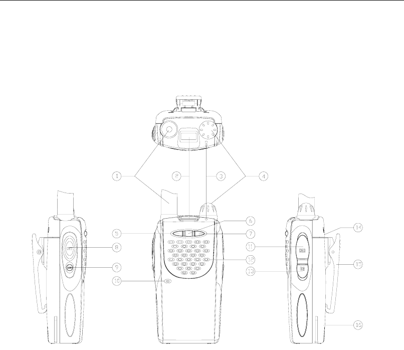
Brief Introduction
1. Antenna
Used to receive or transmit signals.
2. LCD
Displays operation status of the radio.
3. LED indicator
In transmit mode, the red LED will turn on. In receive mode, the green LED will turn on. A
flashing red LED indicates that the battery is low.
4. POWER/VOL Knob
Rotate the volume control clockwise to turn the unit on, fully counter clockwise to turn the unit
off. Increase or decrease volume by adjusting the volume control accordingly.
5. Down key
Adjust the channel downwards.
6. SCAN key
Press the scan key to activate the scan mode. When the radio detects properly coded activity on a
channel, it will stop scanning and listen to that channel.
7. Up key
Adjust the channel upwards.
8. PTT button
To transmit, press and hold PTT button. To receive, release PTT button.

7
9. MONI button
In receive mode, press the MONI key to monitor activity on your selected channel.
10. Microphone
Input audio.
11. Earpiece Jack/ PC programming port
Used to connect external earphone/microphone accessories or used to connect with programming
cable.
12. Speaker
Output audio.
13. DC jack
Used for factory adjustment only.
14. Battery latch
Used to fasten and remove the battery.
15. Belt clip
Used to clip radio on your belt.
16. Battery pack
8
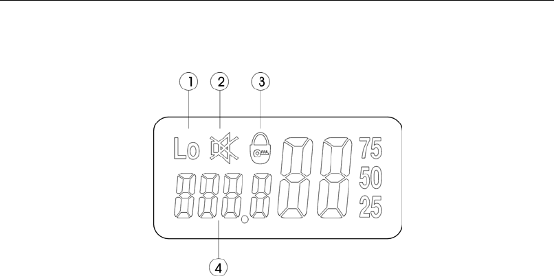
LCD Display
1. Appears when the transmit power of the current channel is set for low power.
2. Appears when the dealer disables the radio’s speaker.
3. Appears when the keys are locked.
4. Display the current channel number.

9
Dealer Operation Description
Keys combination
Key Function
MONI+SCAN Key Lock/unlock (dealer can program it ON/OFF)
MONI+UP Change CTCSS/CDCSS number (dealer can program it ON/OFF)
MONI+DOWN Adjust squelch level 0-9(dealer can program it ON/OFF)
PTT+MONI High/low power (dealer can program it ON/OFF)
Dealer Mode
Turn on the radio while pressing [PTT] and [SCAN] simultaneously, in 3 seconds, the
radio enters Password Check (if password has been set) or Dealer Menu.
1. Password Check
LCD displays “------”. (The first “-”blinks, indicating to enter password.)
(1) For detailed operations, see 4. Password Set.
(2) Dealer Menu can be accessed only after entering correct password.
2. Dealer Menu
LCD displays “RESEty”. (“y” or “n” blinks to indicate yes or no.) There are 9 options:
(1) Reset enabled
LCD displays “ RESEty”. (“y” or “n” blinks to indicate yes or no.)
(2) Tune mode enabled
LCD displays tUNEy. (“y” or “n” blinks to indicate yes or no.)
(3) Channel set enabled LCD displays CHSEty. (“y” or “n” blinks to indicate yes or no.)
(4) Function set enabled
LCD displays FUNCy. (“y” or “n” blinks to indicate yes or no.)
(5) Wired clone enabled
LCD displays CLONEy. (“y” or “n” blinks to indicate yes or no.)
(6) Radio speaker enabled
LCD displays Sp y. (“y” or “n” blinks to indicate yes or no.)
(7) Keys combination enabled
LCD displays ASSIgy. (“y” or “n” blinks to indicate yes or no.)
(8) Adjust Max. channel capability
LCD displays CHNU 99. (99 blinks, indicating to enter new number).
(9) Set new password
LCD displays SECrEt.
Press [SCAN], LCD displays “------”. The first “ –”blinks. See 4. Password Set.
3. Dealer Menu Operations
(1) Press [UP]/[DOWN] to change the digit in cursor.
(2) Press [PTT] to save the change and enter the next menu option or next option setting.
(3) Press [MONI] to directly enter the next menu option or next option setting.
4. Password Set

10
(1) Password contains 6 digits (0-9).
(2) After correct password is checked, a new password can be entered and original one can be
cancelled.
(3) Press [SCAN] to enter password-entering mode.
(4) Press [UP]/[DOWN] to enter digits (0-9).
(5) Press [SCAN] to delete entered password or cancel password.
Delete entered password: LCD displays“------”. The first “-” blinks.
Cancel password: LCD displays “CANCEL”. “CANCEL” blinks.
(6) Press [PTT] to confirm the entered.
If password is less than 6 digits, enter other ones until there are 6 digits.
After entering a 6-digit password, password is checked.
After entering a 6-digit new password, new password is set.
Cancel Password Check when LCD displays “CANCEL”.
(7) Press [MONI] to exit.
If password is being checked, pressing [MONI] cannot exit password-entering mode.
When entering a new password, press [MONI] to exit and enter reset option.
Power On Menu
Turn on the radio while holding down [PTT] and [MONI] simultaneously, in 3 seconds, the following
enabled options are displayed:
(1) Tune mode.
LCD displays “tUNE”.
(2) Channel set
LCD displays “ CHSEt”.
(3) Function set
LCD displays “ FUNSEt”.
(4) Keys combination set
LCD displays “ASSIgn”.
Operations: Press [UP]/[DOWN] to select the next menu option.
Press [PTT] to enter option setting.
Note: All menu options can be enabled or disabled by the dealer in dealer mode.
If one menu option is disabled by the dealer, then this option is skipped; if all options are set invalid,
the radio directly enters user mode.
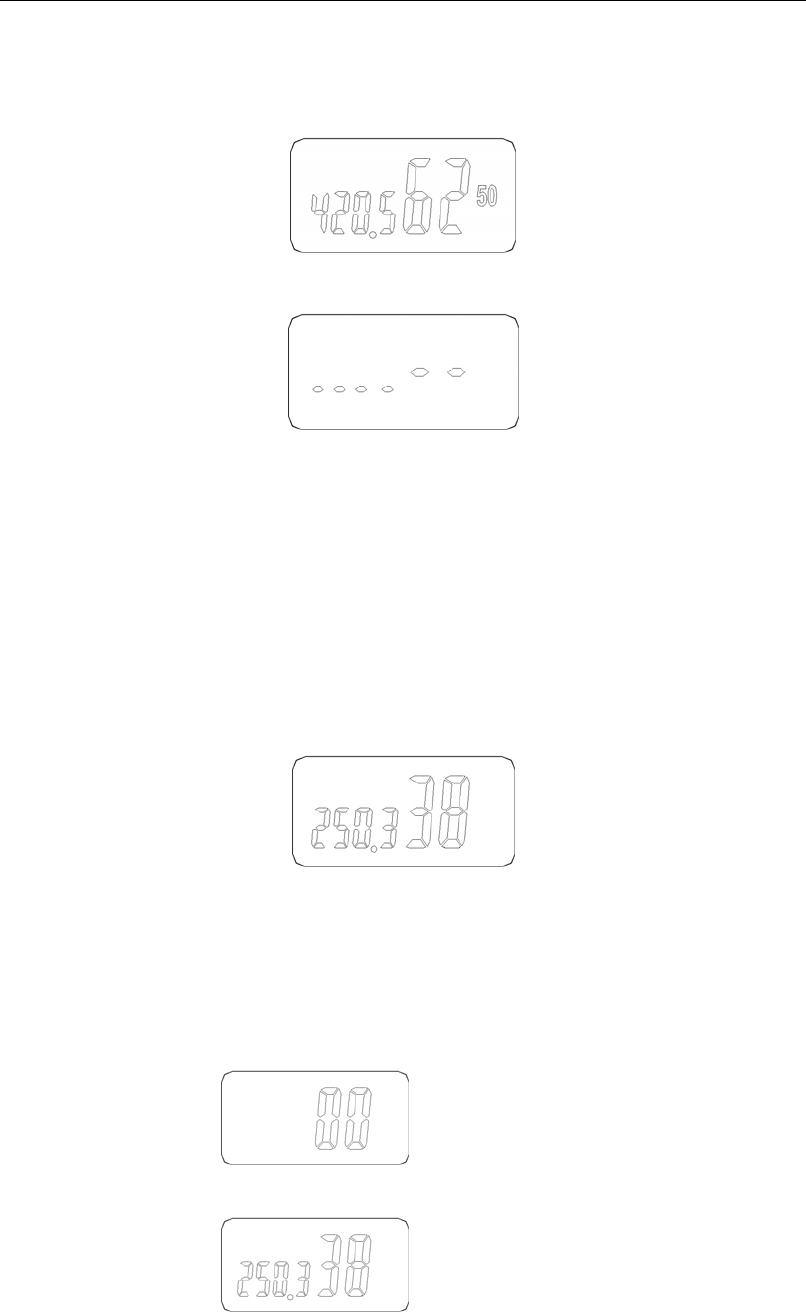
Channel set
1. Select “CHSEt” in Power On Menu. The radio enters channel set mode. Now LCD displays
channel number as follows:
11
Press [UP]/[DOWN] to select the channel which needs to be programmed. Press [MONI] to return
to Power On Menu.
2. Press [PTT], LCD displays the receive frequency of current channel as follows:
Press [SCAN] to toggle LCD display between frequency and blank, as follows:
Frequency change operations:
Press [UP] or [DOWN] to change frequency upwards or downwards. (In step of 5 KHz or
6.25KHz)
Hold down [UP] or [DOWN] to continuously change frequency.
Press [MONI] to toggle step between 1MHz(now the left third digit blinks), 100KHz(now the left
forth digit blinks) and normal step (5 KHz or 6.25KHz).
Holding down [MONI] exceeds 1 second, the step will be toggled between 5KHz and 6.25KHz.
Press [UP] or [DOWN] to change the frequency in corresponding step increments.
Hold down [UP]/[DOWN] to continuously change frequency.
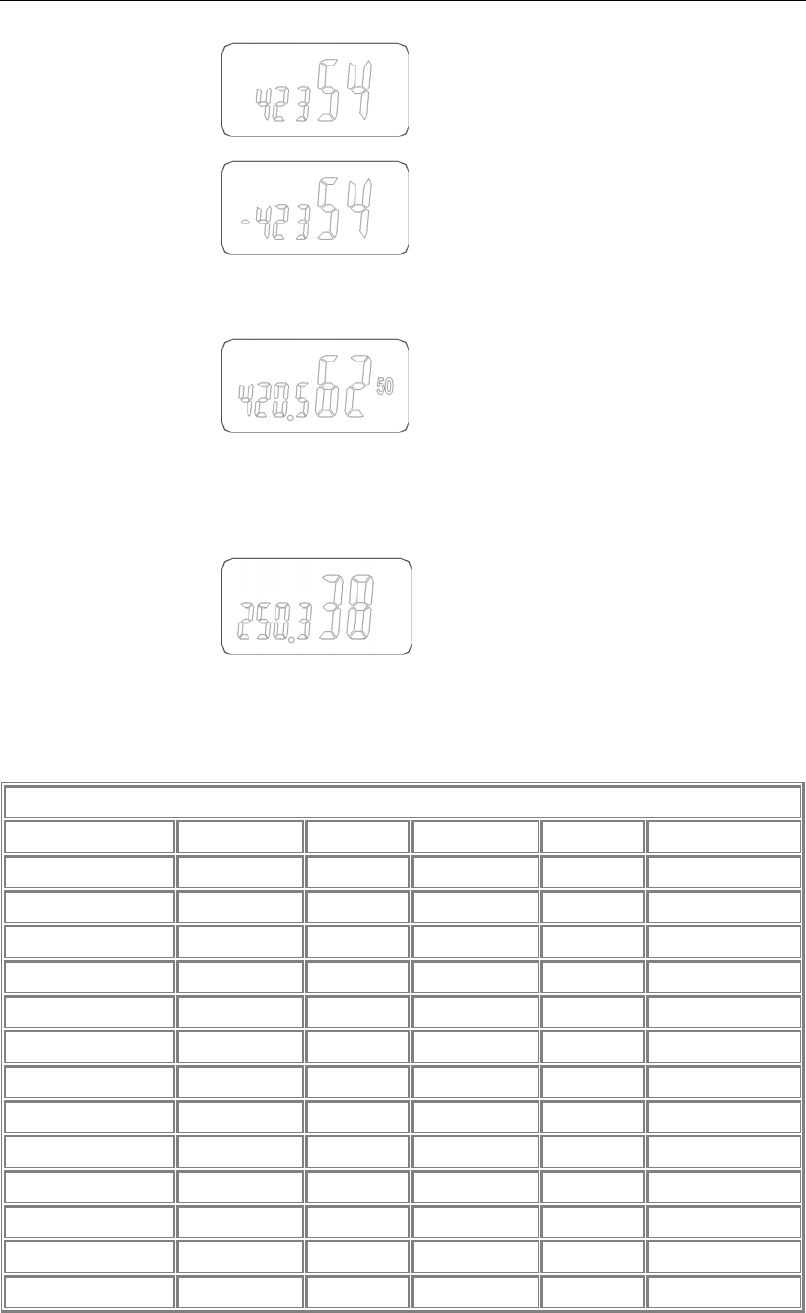
3. Press [PTT], LCD displays receive CTCSS/CDCSS number of current channel:
The right two digits display CTCSS/CDCSS number, and the left 4 digits display CTCSS
frequency or CDCSS code.
Press [UP] or [DOWN] to change CTCSS/CDCSS number upwards or downwards.
Hold down [UP]/[DOWN] to continuously change CTCSS/CDCSS number.
Press [SCAN] to toggle LCD display between OFF, CTCSS, CDCSS and reverse CDCSS, as
follows:
(1) OFF
(2) CTCSS
12
(3) CDCSS
(4) Reverse CDCSS
4. Press [PTT], LCD displays transmit frequency of current channel as follows:
The setting operations are same as those of receive frequency.
5. Press [PTT], LCD displays transmit CTCSS/CDCSS number:
The setting operations are same as those of receive CTCSS/CDCSS.
CTCSS/CDCSS
CTCSS
NO. Freq (Hz) NO. Freq (Hz) NO. Freq (Hz)
00 NO TONE 13 103.5 26 162.2
01 67.0 14 107.2 27 167.9
02 71.9 15 110.9 28 173.8
03 74.4 16 114.8 29 179.9
04 77.0 17 118.8 30 186.2
05 79.7 18 123.0 31 192.8
06 82.5 19 127.3 32 203.5
07 85.4 20 131.8 33 210.7
08 88.5 21 136.5 34 218.1
09 91.5 22 141.3 35 225.7
10 94.8 23 146.2 36 233.6
11 97.4 24 151.4 37 241.8
12 100.0 25 156.7 38 250.3
13
CDCSS
NO. CODE NO. CODE NO. CODE
01 023 29 174 57 445
02 025 30 205 58 464
03 026 31 223 59 465
04 031 32 226 60 466
05 032 33 243 61 503
06 043 34 244 62 506
07 047 35 245 63 516
08 051 36 251 64 532
09 054 37 261 65 546
10 065 38 263 66 565
11 071 39 265 67 606
12 072 40 271 68 612
13 073 41 306 69 624
14 074 42 311 70 627
15 114 43 315 71 631
16 115 44 331 72 632
17 116 45 343 73 654
18 125 46 346 74 662
19 131 47 351 75 664
20 132 48 364 76 703
21 134 49 365 77 712
22 143 50 371 78 723
23 152 51 411 79 731
24 155 52 412 80 732
25 156 53 413 81 734
26 162 54 423 82 743
27 165 55 431 83 754
28 172 56 432
6. Press [PTT], LCD displays “Add”/ “DEL”. Press [UP]/[DOWN] to add /delete the channel
to/from scan list. LCD displays as follows:
(1) Add: add the channel in scan list.
14
(2) dEL: delete the channel from scan list, and the channel (except priority channel) will not be
scanned.
7. Press [PTT], LCD displays “HI”/“LO”. Press [UP]/[DOWN] to toggle RF power between high
and low. LCD displays as follows:
8. Press [PTT], LCD displays “BSy On”/“BSyOFF”. Press [UP]/[DOWN] to toggle Busy Channel
Lockout between ON and OFF.
9. Press [PTT] to save settings. Press [PTT] again to enter the next channel and continue the settings.
When settings are completed, turn off power to exit.
Model set and reset
Short out the two SELF points on PCB, and turn on the power. After a “beep” sounds, (red LED
glows at the same time), LCD displays all signs. And then the two SELF points is released, the radio
enters model set and reset mode, LCD displays BAND 1-22 and red LED goes out.
. Press [up]/[down] to select model number 1-22. (Data of initialization is as the following
table)
. Press [PTT] to confirm selected model and then reset.

15
1CH(C) 2CH(L) 3CH(H) 4CH 5CH 6CH 7CH 8CH 9-99CH
Model Freq. (MHz) IF. (MHz) Tx
(MHz)
Rx
(MHz)
Tx
(MHz)
Rx
(MHz)
Tx
(MHz)
Rx
(MHz)
(MHz)
(MHz)
(MHz)
(MHz)
(MHz)
(MHz)
1 150.000~173.995 +45.05 162.000 162.100 150.000 150.100 173.975 173.900 162.500 162.550 162.600 162.550 162.650
2 136.000~149.995 +45.05 143.000 143.100 136.000 136.100 149.975 149.900 143.500 143.550 143.600 143.550 143.650
3 146.000~173.995 +45.05 160.000 160.100 146.000 146.100 173.975 173.900 160.500 160.550 160.600 160.550 160.650
4 144.000~147.995 +45.05 146.000 146.100 144.000 144.100 147.975 147.900 146.500 146.550 146.600 146.550 146.650
5 136.000~147.995 +45.05 142.000 142.100 136.000 136.100 147.975 147.900 142.500 142.550 142.600 142.550 142.650
6 136.000~173.995 +45.05 155.000 155.100 136.000 136.100 173.975 173.900 155.500 155.550 155.600 155.550 155.650
7 450.000~469.995 -45.05 460.000 460.100 450.000 450.100 469.975 469.900 460.300 460.350 460.400 460.350 460.450
8 400.000~419.995 -45.05 410.000 410.100 400.000 400.100 419.975 419.900 410.500 410.550 410.600 410.550 410.650
9 470.000~489.995 -45.05 480.000 480.100 470.000 470.100 489.975 489.900 480.500 480.550 480.600 480.550 480.650
10 490.000~511.995 -45.05 501.000 501.100 490.000 490.100 511.975 511.900 501.500 501.550 501.600 501.550 501.650
11 220.000~239.995 -45.05 230.000 230.100 220.000 220.100 239.975 239.900 230.500 230.550 230.600 230.550 230.650
12 240.000~259.995 -45.05 250.000 250.100 240.000 240.100 259.975 259.900 250.500 250.550 250.600 250.550 250.650
13 336.000~367.995 -45.05 352.000 352.100 336.000 336.100 367.975 367.900 352.500 352.550 352.600 352.550 352.650
14 368.000~395.995 -45.05 382.000 382.100 368.000 368.100 395.975 395.900 382.500 382.550 382.600 382.550 382.650
15 370.000~389.995 -45.05 380.000 380.100 370.000 370.100 389.975 389.900 380.500 380.550 380.600 380.550 380.650
16 350.000~369.995 -45.05 360.000 360.100 350.000 350.100 369.975 369.900 360.500 360.550 360.600 360.550 360.650
17 406.000~429.995 -45.05 418.000 418.100 406.000 406.100 429.975 429.900 418.500 418.550 418.600 418.550 418.650
18 400.000~429.995 -45.05 415.000 415.100 400.000 400.100 429.975 429.900 415.500 415.550 415.600 415.550 415.650
19 430.000~439.995 -45.05 435.000 435.100 430.000 430.100 439.975 439.900 435.500 435.550 435.600 435.550 435.650
20 438.000~449.995 -45.05 444.000 444.100 438.000 438.100 449.975 449.900 444.500 444.550 444.600 444.550 444.650
21 440.000~469.995 -45.05 455.000 455.100 440.000 440.100 469.975 469.900 455.500 455.550 455.600 455.550 455.650
22 480.000~519.995 -45.05 500.000 500.100 480.000 480.100 519.975 519.900 500.500 500.550 500.600 500.550 500.650
CH QT/DQT OFF OFF OFF OFF OFF OFF OFF 023 023 127.3 151.4
16
Function set
Select “FUNSEt” in Power On Menu. The radio enters function set mode.
Setting
No.
(PTT)
Function
name
Settings
(Defaults are
underlined)
Display
([UP]/
[DOWN])
Specifications
OFF OFF Monitor function is OFF
Monitor
Momentary
1 Hold down [MONI] to cut off signaling temporarily.
Monitor Lock 2 Press [MONI] to cut off signaling. Switches each time
[MONI] is pressed.
1
Monitor
SQ OFF
Momentary
3 Hold down [MONI] to open squelch.
Carrier
operated
CO
2 Scan
Time operated TO
3 Dropout
Time
0.5-5s
5s
0.5-5
5
Time until scan restarts when it’s stopped by
transmission. Step: 0.5s
OFF OFF No priority channel
Fixed 1 Fixed priority channel
4 Priority
setting
Selectable 2 Selectable priority channel
5 Priority
channel
1-N (2-99)
1
1-N Valid only when the fixed priority channel is set.
6 Look
Back
0.5-5s
(Step: 0.5s)
1.5s
0.5-5.0 The period priority channel is checked while scan
stops at a non-priority channel during priority scan.
Last call 1 Last channel at pause in scan. Channel where scan is
stopped. Channel at start of scan when scan not
stopped at all.
Last used 2 Last channel transmitted during scan.
Channel where scan is stopped. Channel at start o
f
scan when scan not stopped at all.
Scan start 3 Channel where scan started during scan.
Channel where scan is stopped.
7 Revert
channel
select
Priority 4 Priority channel during scan. Channel where scan is
stopped.
8 Squelch
level
0-9
5
0-9
5
17
Setting
No.
(PTT)
Function
name
Settings
(Defaults are
underlined)
Display
([UP]/
[DOWN])
Specifications
9
Time Out
timer
(TOT)
0
1-10
6
OFF
30-300
180
OFF: 10 minutes
(Step: 30s)
ON
ON
ON: Beep is on.
10
Beep
OFF OFF OFF: Beep is off.
ON ON ONBacklight is enabled.
11
Backlight OFF OFF OFF: backlight is disabled.
Wideband
25
2525.0KHz
12
Wideban-
d/Narrow
-band
Narrowband 1250 1250: 12.5KHz
ON
ON
13
Battery
save
OFF OFF
Wired clone
First enable Wired Clone Mode in dealer mode. (Refer to “Dealer Mode” in page 5).
Turn on the radio while holding down [MONI], in 2 seconds, LCD displays“clone”; Release [MONI],
the radio enters wired clone mode.
(1) Press PTT to enable/disable Wired Clone Mode of the cloned radio. The Wired Clone Mode
settings of the original radio will not be changed.
Pressing PTT button, the green LED flashes two times with a beep to enable Wired Clone Mode;
the red LED flashes two times with two beeps to disable.
Entering Wired Clone Mode, the default is disabling the Wired Clone Mode of the cloned radio.
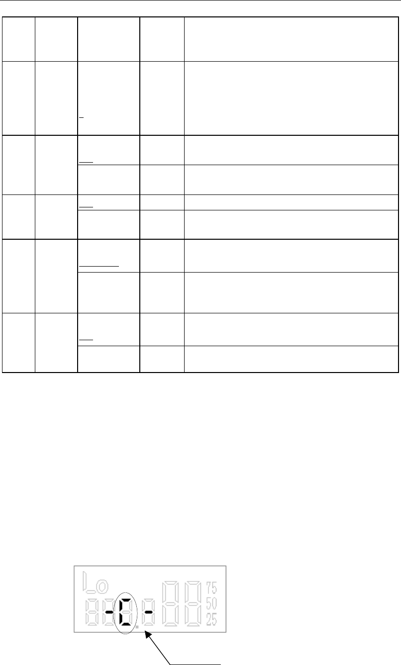
(2) Press [MONI], LCD displays “-C-“, clone begins and “c” blinks at the same time; after clone
completes, blink stops, and LCD displays “-c-End”.
Blink

18
PC programming
Connect a PC and a radio with a programming cable, and then program the radio by the PC.
1). Write data into the radio, green LED glows; read data from the radio, red LED glows.
During programming, LCD displays as cloning, “c” blinking. When programming is complete,
blink stops and LCD displays“-c-End”.
2). When PC tune mode begins, LCD displays “tune”. There are the following options in the tune
mode:
. Low battery alert level
LCD displays “ tuneb”.
. SQL9
LCD displays “ tune9”(center frequency)
. SQL3
LCD displays “tune3” (center frequency)
. CTCSS deviation (Wide)
LCD displays“tune1”(center frequency)
.CTCSS deviation (Narrow)
LCD displays“ tune2” (center frequency)
.CDCSS deviation (Wide)
LCD displays“ tune5” (center frequency)
.CDCSS deviation (Narrow)
LCD displays“ tune6” (center frequency)
During PC tuning, the last character on LCD is displayed and blinks.
Tune mode
Select “tunE” in Power On Menu. The radio enters tune mode.
There are following options in tune mode:
. Low battery alert level
LCD displays “BAtREF”.
. SQL9
LCD displays “ sql 9” (center frequency)
. SQL3
LCD displays “sql 3” (center frequency)
. CTCSS deviation (Wide)
LCD displays “CtCSS”(center frequency)
. CTCSS deviation (Narrow)
LCD displays“ CtCSSn” (center frequency)
. CDCSS deviation (Wide)
LCD displays“ CdCSS” (center frequency)
. CDCSS deviation (Narrow)
LCD displays “CdCSSn” (center frequency)
. Center Frequency check
LCD displays “SENS C” ([PTT]: R/T, SCAN, wide/narrow)
. Low Frequency Check
LCD displays “SENS L” ([PTT]: R/T, SCAN, wide/narrow)
(10). High Frequency Check

19
LCD displays “SENS H” ([PTT]: R/T, SCAN, wide/narrow)
(11). Center Frequency with CTCSS 250.3 check
LCD displays “SENC 38” ([PTT]: R/T, SCAN, wide/narrow)
Operations: Press [UP]/[DOWN] to select the next menu option.
Press [PTT] to enter option settings:
In [1]-[7] options, LCD displays blinking digits. Now press [UP]/[DOWN] to adjust, press [MONI]
to exit.
In [8]-[11] options, C/L/H blinks, indicating center frequency, low frequency or high frequency. If
wideband, “F” is displayed; if narrowband, “Fn” is displayed.
Now press [MONI] to exit; press [SCAN] to switch the band between wide and narrow. Press
[UP]/[DOWN] to change power between high and low.
Note: Center, low and high frequency can be changed by PC programming software.
Keys combination set
Select “ASSIgn” in Power On menu. The radio will enter keys combination set mode.
1. Set [MONI]+[UP] valid/invalid. LCD displays UP on/oFF.
2. Set [MONI]+[Down] valid/invalid. LCD displays dn on/oFF.
3. Set [MONI]+[SCAN] valid/invalid. LCD displays SCN on/oFF.
4. Set [MONI]+[PTT] valid/invalid. LCD displays Ptt on/oFF.
Above keys combinations are valid only in user mode.
Operations:
Press [UP]/[DOWN] to toggle the keys combination between on and off.
Press [PTT] to save the setting and enter the next option setting.
Press [MONI] to exit the mode and return to “ASSIgn” option in Power On Menu.