Northfield Telecommunications d b a Advanced Wireless Communications AWR-ERM100 Embedded Radio Module User Manual AWR ERM100 MANUAL 201609x
Northfield Telecommunications, Inc. d/b/a Advanced Wireless Communications Embedded Radio Module AWR ERM100 MANUAL 201609x
User Manual

AWR-ERM100
User manual
AdvancedwirelessCommunication
FCC License Information
Your Advanced Wireless Communications radio operates on communications frequencies which are subject to FCC (Federal Communications Commission) Rules &
Regulations. FCC Rules require that all operators using Private Land Mobile radio frequencies obtain a radio license before operating their equipment. Application for
license must be made on FCC form 601, and schedules D, E, and G.
FAX: Forms can be obtained by fax from the FCC Fax-On-Demand system. Call 1-202-418-0177 from your fax machine and request document number 000600 for the
form, schedules, and instructions.
MAIL: Forms can be ordered by telephone, and will be sent to you by first class mail. Call the FCC Forms Hotline at 1-800-418-FORM (1-800-418-3676).
INTERNET: Form 601 and instructions can be downloaded from the FCC Forms website at: http://www.fcc.gov/Forms/Form601/601.html
Before filling out your Form 601 application Technical Data section, you must
decide which frequency (or frequencies) you will operate on.
Questions? Call the FCC for license application questions at 1-888-CALL-FCC (1-888-225-5322).
If you have any questions, call Advanced Wireless Communications at 1-800475-5852
FCC WARNING
This equipment generates or uses radio frequency energy. Changes or modifications to this equipment may cause harmful interference unless the modifications are
expressly approved in the instruction manual. The user could lose the authority to operate this equipment if an unauthorized change or modification is made.
*Transmit no more than 50% of the time. To transmit (talk), push the PushTo-Talk (PTT) button. To receive calls, release the PTT button. Transmitting 50% of the time
or less is important since the radio generates measurable RF energy exposure only when transmitting (in terms of measuring standards compliance).
Contains FCC ID : Q 9 SAWR-ERM100.
The module must be labeled with its own certification number, and, if the certificati on number is not visible when the module is installed inside a host
device, then the host device into which the module is installed must also display a label referring to the enclosed module. For details as follows:
User Safety Information
PLEASE READ THIS IMPORTANT INFORMATION BEFORE USING YOUR ADVANCED WIRELESS COMMUNICATIONS PORTABLE TWO-WAY RADIO.
◊ Only qualified technicians are allowed to maintain this product.
◊ To avoid electromagnetic interference, turn off your radio in places where posted notices instruct you to do so. Hospitals or health care facilities may be using
equipment that is sensitive to external RF energy. When traveling on aircraft, turn off your radio when the airline crew instructs you to do so.
◊ When in vehicles equipped with an air bag, do not place a portable radio in
the airbag deployment area.
◊ Turn off your radio prior to entering any area with a potentially explosive
atmosphere. Do not remove, install, or charge batteries in such areas.
◊ To avoid possible interference with blasting operations, turn off your radio
when you are near electrical blasting caps.
◊ Do not expose the radio to direct sunlight for long periods of time. Do not
placetheradioindirectcontactwithanyheatingsource.
FCC/IC Radiation Exposure Statement:
This equipment complies with FCC/IC radiation exposure limits set forth for an controlled environment.
This equipment should be installed and operated with minimum distance 20 cm between the radiator& your body
and with maximum antenna gain 5dBi.
Cet équipement est conforme aux normes FCC /IC limites d'exposition aux radiations
dans
environnement
non contrôlé.
Cet équipement doit être installé et utilisé avec un minimum la distance de 20 cm entre le radiateur ou votre corps
et avec antenne maximale gagner 5dBi.
IC warning:
Per RSS GEN section 3.21 requirement, The module must be labeled with its own certification
number, and, if the certification number is not visible when the module is installed inside a host
device, then the host device into which the module is installed must also display a label referring
to the enclosed module. For details as follows:
Contains IC: 4651A- AWRERM100
.
ParRSSGENsection3.21exigence,Lemoduledoitêtreétiquetéavecsonproprenumérode
certification,et,silenumérodecertificationnesontpasvisibleslorsquelemoduleest
installéàl'intérieurd'undispositifhôte,ledispositifhôtedanslequellemoduleestinstallé
doitégalementafficheruneétiquettefaisantréférenceaumoduleci‐joint.Pourplusde
détailscommesuit:
Contient IC:4651A‐AWRERM100.
General
AWR-ERM100 transceiver module operates in UHF frequency bands. Typical radio parameters such as frequency, power, squelch level and audio
input and output gain are PC adjustable. The transceiver is a single board unit with components on one side
The unit supports voice through a microphone input and a nominal one watt speaker output or data through the auxiliary in and auxiliary out ports.
Each radio can be programmed to contain a unique set of 16 operating frequencies and sub-audible tones. There are two way to select the channel.
One is that the channel selection is done in a binary manner on the CS3, CS2, CS1 and CS0 inputs in the auxiliary in port. One is to press the channel
button. Separate RX and TX Quiet Call (CTCSS) or Digital Quiet call (DCS) tones can be programmed per channel. Transmitter wide or narrow
deviation can be programmed on a per channel basis. The unit is factory set up to transmit 2 or 4 watts when operating at 12 VDC.
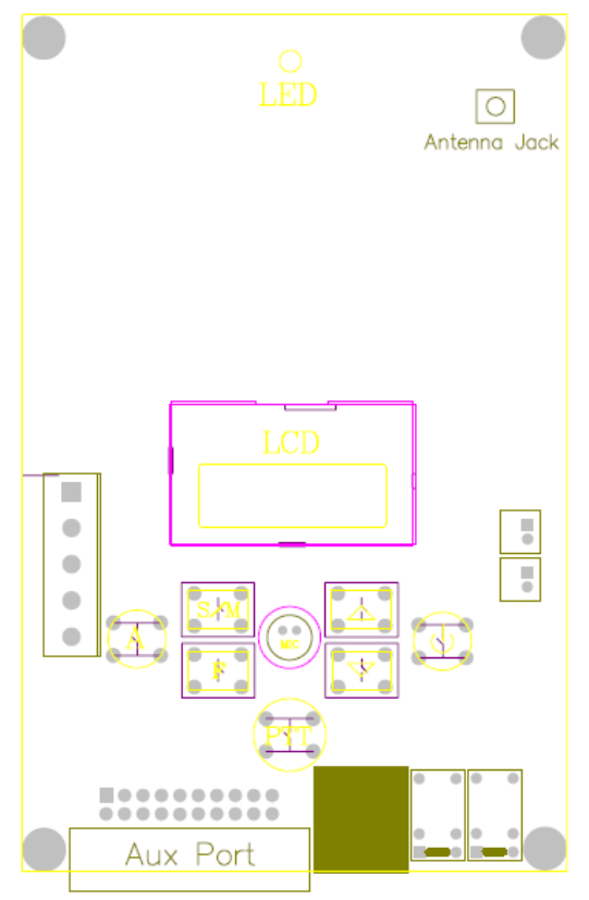
GETTING ACQUAINTED
1. LED: TX and RX indicator
2. LCD
3. S/M (programmable function key)
4. F (programmable function key)
5. A (programmable function key)
6. PTT ( programmable key )
7. Channel + key
8. Channel - key
9. B power on key
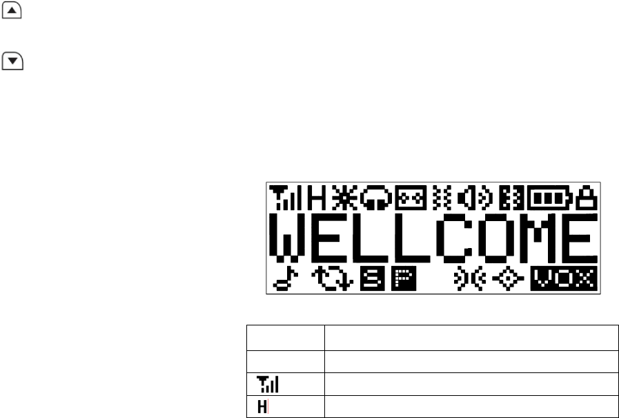
LCD DISPLAY SYMBOLS
SYMBOLFUNCTION
WELLCOMEChannel number/Channel alias/Channel frequency
RSSI
High Power:the current channel is high power (H/M/L)
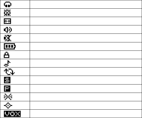
Headset function enable/ headset connected
Headset function disable
Recorder function enable/ Flashing when no space
Speaker opened
Speaker function disable
Battery indicator
Keypad lock
DTMFsignallingenable
Scan
Thecurrentchannelisinscanlist
Thecurrentchannelispriorchannel
Companderenable
Scramblerenable
VOXenable
OPERATION
The AWR-ERM100 have two operation mode, one is use the Key, one is the sub DB-20.
Key mode:
TURN THE UNIT ON/OFF
Press and hold B until you hear a beep and the LCD display appears or disappears.
TALK TO ANOTHER RADIO
To talk to another radio (transceiver):
1. Press and hold “Mon”(function key) to check if the channel is free.
2. Press and hold PTT and speak into the microphone to transmit.

3. Release PTT once you have finished speaking to allow other radios to respond. The radio transceiver will automatically hear received transmissions.
NOTE: You can only communicate with another radio (transceiver) that is on the same channel and using the same CTCSS/DCS code as your radio (transceiver).
SELECT A CHANNEL
The transmitter and receiver must be on the same channel using the same CTCSS code or DCS code in order for you to communicate with another party.
To select between maximum 16 channels (the CTCSS code or DCS code is set by PC program):
1. Press to increase channel number.
2. Press to decrease channel number.
SCAN FOR A CHANNEL
1. Press the key (programmable SCAN ) to enter scan mode.
2. Press PTT to enter the Tx mode on the last valid channel in memory and continue to scan after the button is released.
DB-20 OPERATION
The sub D-20 contains signal, control and power lines and the RF connector receives low level signals and transmits power. The radio’s 16 transmit and receive
frequencies are programmed via a PC. Pins 1, 2, 3 and 4 of the DB-20 connector select the channel. The receiver bandwidth is fixed in either a wide or narrow
bandwidth and should be ordered as such from the factory. The transmitter can be programmed for either wide or narrowband deviation on a channel by channel basis.
A monitor input activates both speaker and auxiliary outputs, allowing a modem to continually search for a signal. A high/low RF power control pin allows selection of
transmitter power level. Separate microphone and auxiliary inputs allow either pre-emphasized voice or flat data to be transmitted. Only one input should be driven at a
time. Separate speaker and auxiliary outputs allow either de-emphasized voice or flat data output. A carrier detect output is pulled high when the channel is busy.
Alternately, the MON ITOR input can be used as a carrier and tone detector output.
A dual colored LED appears on the edge of the board. It has the following functions:
Bright RED while transmitting Bright GREEN when carrier is present on channel,
INSTALLATION
The antenna should be installed in a location to minimize radiation to the AWR-ERM100 board and DB-20 connector harness. Antenna positioning is also important in
minimizing interference to the receiver. PCs and motors are notorious producers of electrical noise. In a noisy environment the receiver squelch level can be raised to
avoid unwanted spurious reception.
To maximize transmission power, the power supply cable should be of sufficient gauge to minimize voltage drop. Measuring the voltage between pin 5 and pin 15 on
the DB-20 connector while transmitting will show the actual radio voltage. For higher duty transmitter cycles, heating of the board should be considered. An external heat
sink can be added to the bottom of the board only version using the two mounting holes on both sides of the RF PA shield. On the shielded board model the shield will
help heat sink the unit. On the encased model the heat is conducted out of the aluminum end cap opposite the connectors. When transmitting with higher duty cycle
usage at elevated ambient temperatures, without heat sinking, the internal board heat may push the reference oscillator Y301 temperature higher than the 60 ºC
specified limit for 2.5 ppm (VHF) or 1.5 ppm (UHF) operation. Some form of additional cooling may be employed to avoid this situation.
SUB D 20 PIN CONNECTOR
The AWR-ERM100 is equiped with a 20 pin female sub D connector with the following functions:
Pin# Function
1 Least significant channel select bit (CS0)
2 Channel select 1 (CS1)
3 Channel select 2 (CS2)
4 Most significant channel select (CS3)
5 + 8 to 20 VDC input
6 Carrier detect output (pulls to 3.3 VDC through internal 1000 ohms)
7 Auxilary input
8 Auxilary ouput
9 Auxilary control PIN
10 Microphone input
Volume control (RSSI option)
11 DC output (5V)
Auxilary monitor input (pull to ground to open squelch). Can be used for tone detect, see below.
12 Red LED control
13 Green LED control Speaker output
13 Carrier detect output (pulls to 3.3 VDC through internal 390 ohms)
14 Reserved
15 Ground
16 PTT (pull to ground to transmit)
17 PC programing port
18 PC programing port
19 Speaker +
20 Speaker -

TROUBLESHOOTING
See below for some common problems and their remedies. DO NOT attempt any repairs yourself. This will invalidate your warranty.
PROBLEM POSSIBLE CAUSES / REMEDIES
Can’t turn the radio on
• Check that the power input if is correctly
installed
Can’t communicate with other radios
• For this and all other issues contact
Advanced Wireless Communications at
1-800-475-5852 or visit
www.advancedwireless.com for more
information.
VOX function is not working
• Check the headset is correctly plugged
in and is compatible with the module.