Northrop Grumman Information Technology sector DMS WLERVA Vehicle Extended Range Amplified WLAN System User Manual CERTIFICATE OF COMPLIANCE

Northrop Grumman Corporation, Information Technology sector, DMS Vehicle Extended Range Amplified WLAN System CERTIFICATE OF COMPLIANCE
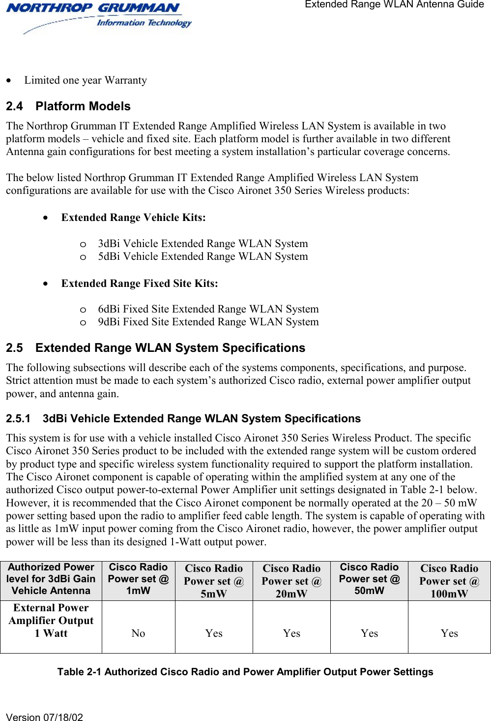
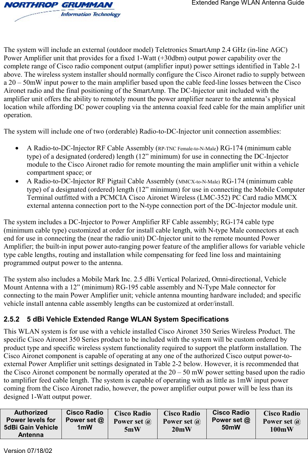
Manual

Rhein Tech Laboratories  Report number:  2002050 360 Herndon Parkway  FCC:  Part 15.247 Suite 1400  Industry Canada:  RSS-139 FCC ID:  P6G-WLERVA Herndon, VA   20170 http://www.rheintech.com  M/N:  NGIT Vehicle Extended Range Amplified WLAN System      Page 55 of 77   APPENDIX L:  MANUAL  Please see the following pages.
      Extended Range WLAN                                                     System Guide     Version 07/18/02         Northrop Grumman Information Technology Extended Range Amplified Wireless LAN System  (For Cisco Aironet 350 Series Wireless Product)    System Description, Configuration and Installation Guide         July 18, 2002   Northrop Grumman Information Technology Defense Mission Systems Wireless LAN Center Of Excellence 4065 Hancock Street, Suite 200 San Diego, California 92110-5151
      Extended Range WLAN                                                     System Guide     Version 07/18/02    Table of Contents  1 INTRODUCTION ............................................................................................................................................1 1.1 ABOUT THIS GUIDE ...........................................................................................................................................1 1.2 WHO SHOULD USE THIS GUIDE .........................................................................................................................1 1.3 NOTES AND WARNINGS TO THE USER AND INSTALLER .....................................................................................1 1.3.1 System Applicability................................................................................................................................1 1.3.2 Interference and Equipment Limits..........................................................................................................1 1.3.3 Cautions and Warnings ............................................................................................................................2 2 SYSTEM DESCRIPTION................................................................................................................................3 2.1 EXTENDED RANGE WLAN SYSTEM INFRASTRUCTURE.....................................................................................3 2.2 GENERAL DESCRIPTION.....................................................................................................................................7 2.3 SYSTEM FEATURES............................................................................................................................................7 2.4 PLATFORM MODELS ..........................................................................................................................................8 2.5 EXTENDED RANGE WLAN SYSTEM SPECIFICATIONS .......................................................................................8 2.5.1 3dBi Vehicle Extended Range WLAN System Specifications ................................................................8 2.5.2 5 dBi Vehicle Extended Range WLAN System Specifications ...............................................................9 2.5.3 6 dBi Fixed Site Extended Range WLAN System Specifications .........................................................10 2.5.4 9 dBi Fixed Site Extended Range WLAN System Specifications .........................................................11 2.5.5 Wireless LAN External Amplifier .........................................................................................................12 2.5.6 Additional Wireless LAN System Components.....................................................................................14 3 CONFIGURING THE EXTENDED RANGE WLAN SYSTEM..................................................................14 3.1 SETTING THE CISCO AIRONET CHANNEL SETTINGS.........................................................................................14 3.2 CONFIGURING THE CISCO AIRONET RADIO UNIT ANTENNA CONNECTION PORT ............................................15 3.3 CONFIGURING THE CISCO AIRONET RADIO UNIT OUTPUT POWER SETTING ...................................................15 3.4 OTHER WIRELESS LAN SYSTEM CONFIGURATIONS........................................................................................16 4 INSTALLATION ...........................................................................................................................................16 4.1 INSTALLATION NOTES .....................................................................................................................................16 4.1.1 Primary Required Tools .........................................................................................................................16 4.1.2 Other Required Equipment.....................................................................................................................16 4.1.3 Helpful Tools and Equipment ................................................................................................................16 4.1.4 Installation Site Survey ..........................................................................................................................16 4.1.5 Installation Safety and Equipment Warnings .........................................................................................18 4.1.6 Cisco Aironet Programming and Settings ..............................................................................................18 4.1.7 Antenna Installation ...............................................................................................................................18 4.2 INSTALLING THE FIXED SITE EXTENDED RANGE (AMPLIFIED) WLAN SYSTEM .............................................19 4.2.1 Installing and Cabling the Antenna and Amplifier Unit.........................................................................19 4.2.2 Installing and Connecting the Cisco Aironet 350 Series Radio Device .................................................20 4.3 INSTALLING THE VEHICLE EXTENDED RANGE (AMPLIFIED) WLAN SYSTEM.................................................21 4.3.1 Installing and Cabling the Antenna and Amplifier Unit.........................................................................21 4.3.2 Installing and Connecting the Cisco Radio Device................................................................................22 5 POST INSTALLATION TESTING...............................................................................................................25 5.1 BASIC SYSTEM OPERATIONAL CHECKS ...........................................................................................................25 5.2 WLAN SYSTEM DIAGNOSTICS ........................................................................................................................25
      Extended Range WLAN                                                     System Guide     Version 07/18/02    1 Introduction 1.1  About this Guide This guide provides for a system technical description and generalized overview of the Northrop Grumman IT Extended Range Amplified WLAN System engineered for use with the Cisco Aironet 350 Series Wireless product. It also sets forth the mandatory technical parameters, installation specifics, warnings, and configuration steps necessary for professional wireless system installation. Adherence to the installation parameters set forth in this guide is essential for compliance with current FCC rules, regulations, and Northrop Grumman FCC ID Grant P6GERWLVA and P6GERWLFA. It is not the intention of this guide to describe all the necessary installation facets for a complete wireless LAN and antenna system installation. Installation details such as the mounting the wireless LAN radio hardware, network cabling, antenna cabling, antenna mast/tower installation, and/or antenna grounding systems should be referred to a professional WLAN system installer. This guide is specific only to the use of and equipment configuration parameters necessary for properly installing the associated Northrop Grumman IT amplified WLAN system within the overall wireless LAN system. This installation guide is over packed with each Northrop Grumman IT Amplified WLAN System and it is intended to supplement the Cisco Aironet product and other equipment manufacturer User and Installation Guides included within the WLAN system for the individual system components. This Installation guide is intended for use by the professional wireless LAN system installer.  1.2  Who Should Use this Guide Installation of the Northrop Grumman Extended Range Amplified WLAN System should be accomplished only by a qualified wireless LAN system installer who is: •  Knowledgeable with the use, installation and configuration procedures for the Cisco Aironet 350 Series Wireless product line and associated networking components. •  Knowledgeable with each system component’s equipment User’s and Installation Guide.  •  Knowledgeable with the installation and configuration procedures for the site’s network infrastructure system and wiring. •  Knowledgeable with the installation procedures, safety, and code requirements for the site’s antenna, antenna mast, antenna cabling, and lightning protection installation. Northrop Grumman IT highly recommends that the antenna installation be performed by a qualified antenna installation professional. 1.3  Notes and Warnings to the User and Installer 1.3.1 System Applicability The Northrop Grumman IT Extended Range Amplified WLAN System is offered for professional installation to support enhanced wireless LAN mobility for Public Safety, Department of Defense (DOD), Industrial, and Home Land Defense agencies. The Northrop Grumman IT Extended Range (Amplified) System is not applicable for sale, installation, or use to the general public for private and/or other public use. 1.3.2  Interference and Equipment Limits This equipment is to be operated in compliance with the limits of Part 15 of the Federal Communications Commission (FCC) Rules. As such, operation of this equipment may not cause harmful interference, and
      Extended Range WLAN                                                     System Guide     Version 07/18/02    this equipment must accept any interference received, including interference that may cause undesired performance.   FCC Part 15 rules and specifications are designed to limit harmful interference in a residential and commercial installation. This equipment generates, uses, and can radiate radio frequency energy. This equipment may cause harmful interference to radio communications if not installed and operated according to the instructions provided in this manual. However, proper installation and operation is no guarantee against interference. If interference to radio or television reception is noticed, turn this equipment off and on to determine if this equipment is causing the interference. If so, the installer/user is encouraged to attempt to correct the problem using any of the following measures:  •  Change antenna position and/or orientation. •  Provide more separation between the equipment and receiver. •  Insure the equipment is not connected to the same circuit (power) as the receiver. •  Reduce the radio transmitter power output level •  Consult with your professional wireless system installer for interference mitigation.  NOTE: Any changes or modifications of the equipment not expressly approved by Northrop Grumman IT could void the WLAN system grant of operation and void the authority of the user to operate the equipment. 1.3.3  Cautions and Warnings  CAUTION: The radiated output power of this product meets with FCC radio frequency (RF) exposure limits. However, this equipment should be used in such a manner as to minimize the potential for human exposure. Table 1-1 below addresses the Maximum Permissible Exposure (MPE) distances that must be maintained for each extended range WLAN system model and antenna type.  System Platform & Antenna Type Specified Antenna Gain (dBi) Max. Cisco Aironet Radio Output Power (dBm) Max. Amplifier Output Power (dBm) Max. FCC EIRP 4 Watts  (+36dBm) Maximum Permissible Exposure (MPE) Distance cm (inches) Vehicle Omni-Directional  2.5dBi  100mW (+20dBm)  1 Watt (+30dBm)  <4 Watts EIRP (33dBm)  20cm (7.9 inches) Vehicle Omni-Directional  5dBi  100mW (+20dBm)  1 Watt (+30dBm)  <4 Watts EIRP (35dBm)  20cm (7.9 inches) Fixed Site Omni-Directional  6dBi  100mW (+20dBm)  500mWatt (+27dBm)  <4 Watts EIRP (+33dBm)  20cm (7.9 inches) Fixed Site Omni-Directional  9dBi  100mW (+20dBm)  500mWatt (+27dBm)  4 Watts EIRP (+36dBm)  20cm (7.9 inches)  Table 1-1 Maximum Permissible Exposure Distance For Model and Antenna Type
      Extended Range WLAN                                                     System Guide     Version 07/18/02      WARNING: When using the Northrop Grumman Extended Range Amplified WLAN System in the United States (or where the FCC rules apply), it is the responsibility of the professional installer to ensure that only the configurations shown in Table 1 above and else where described in this manual are used. The use of any other configuration other than those listed herein is expressly forbidden in accordance with FCC rules CFR47 part 15.204.  Northrop Grumman IT is not responsible for any interference caused by unauthorized modification or configuration programming of this device or the substitution or attachment of antennas and equipment other than that specified by Northrop Grumman IT. 2 System Description 2.1  Extended Range WLAN System Infrastructure The Northrop Grumman IT extended range WLAN (notional) infrastructure consists principally of installing wireless LAN Access Points (APs) with an extended range (amplified) system at designated agency or city owned buildings and sites that have traditional wired network access (T-1, Fiber, or other medium) connectivity into the agency’s overall Wide Area Network (WAN) infrastructure. In conjunction with this fixed site “wireless-to-wired” infrastructure, designated agency vehicles will be additionally equipped with an extended range (amplified) WLAN vehicle system that will allow the vehicle’s installed Mobile Data Computer (MDC) to obtain a high-speed wireless data connection to any fixed site Access Point within the vehicle’s extended LOS range. This wireless LAN connection between the vehicle and the fixed site AP will provide for a significantly enhanced wireless LAN system capability for communicating back to the agencies backbone WAN infrastructure. The extended range WLAN system will essentially extend the WAN fixed site infrastructure currently in placed within a designated area to be extended wirelessly to any mobile MDC vehicles operating within the wireless cell range (zone) of that designated fixed site.   Figure 1 on the next page illustrates a notional Extended Range (Amplified) WLAN infrastructure. It is based solely on a baseline concept of offering an extended range wireless LAN connectivity between mobile data computer vehicles operating within extended LOS range to any one of the identified WLAN cell sites or fixed (AP) relay stations for seamless wireless connectivity back into the agency’s supporting WAN infrastructure.   Additionally, Figures 2 and 3 following are provided to describe the Extended Range WLAN system’s individualized configuration (block) diagrams for both the Vehicle and Fixed Site WLAN platforms.
                                      Extended Range WLAN Antenna Guide   Version 07/18/02                                       Figure 1. Notional Extended Range WLAN System Architecture Police or Fire Headquarters   County Office Center    County  Hospital    Mobile Unit   AP   AP   AP   T-1 or Fiber WLAN to  Mobile Units     WLAN to Mobile Units    WLAN to  Mobile Units       Wired LAN  Connectivity  to Remote Sites       WLAN to  Mobile Units     MDC   AP       WLAN Cell Site   Station 29   MDC   Mobile Unit   AP         Station 28       AP       WLAN Cell Site   Station 30         AP       WLAN Cell Site   Station 27       AP   WLAN Cell Site   Station 1   Cat 5 to WAN     AP       WLAN Cell Site   Station 3       AP   WLAN to  Mobile Units     WLAN Cell Site   Station 2       WLAN to  Mobile Units WLAN to  Mobile Units WLAN to  Mobile Units WLAN to  Mobile Units WLAN to  Mobile Units Cat 5 to WAN Cat 5 to WAN Cat 5 to WAN Cat 5 to WAN
                                      Extended Range WLAN Antenna Guide   Version 07/18/02       Figure 2. Vehicle Extended Range WLAN System (Block) Diagram 2.5 dBi or 5 dBiVehicle or TrunkMountedOmni directionalA n te n n a        DC In je c to rDC-Injector ModuleM ain  P ow er A m plifier U nitTo Intra-V e hicle A uxilia ry D e vice s(Printer, Vehicle AP, Fingerprint Scanner, etc.)P C  C ard In s erted  in to  M D C  P C M C IA  S lo tM o b ile D ata  Computer (MDC) TerminalLMC350C isco  Airo n et 3 50  S e ries               LM C  35 0 P C  C a rd             Pow er Output 100m W  maxLM C 350 PC Card Vehicle ConfigurationCisco Aironet Radio Vehicle Configurations:LM C-350 PC Card RadioorW ork Group Bridge RadioRadio-to-DC InjectorRF Cable (feedline)(M M C X  P lug -to-N -M ale)OR(R P TN C -M ale-to -N -M ale)12” RG-174 Type(m in im u m )Equipm ent M ounted/Located in Vehicle Trunk or Other Available Vehicle Compartm ent Storage SpaceTe le tron ic sM ain  Am plifie r U n itPower Output1 W attDC In je c to rM ain  P ow er A m plifier U nitAn ten n a-to-P A  R F  C ab le12” R G -195  T yp e (m inim u m )DC In je c to rM ain  P ow er A m plifier U nitCat 5 Ethernet To Intra-V e hicle A uxilia ry D e vice s(Printer, Vehicle AP, Fingerprint Scanner, etc.)Cisco Aironet 350 SeriesW ork Group Bridge Unit100 mW  (m ax)     To  Intra -V e hicle A u x ilia ry D e vices(Printer, Vehicle AP, Fingerprint Scanner, etc.)VehicleHub P C  C ard In s erted  in to  M D C  P C M C IA  S lo tM o b ile D ata  Computer (MDC) TerminalLMC350C isco  Airo n et 3 50  S e ries               LM C  35 0 P C  C a rd             Pow er Output 100m W  maxLM C 350 PC Card Vehicle ConfigurationP C  C ard In s erted  in to  M D C  P C M C IA  S lo tM o b ile D ata  Computer (MDC) TerminalM o b ile D ata  Computer (MDC) TerminalLMC350C isco  Airo n et 3 50  S e ries               LM C  35 0 P C  C a rd             Pow er Output 100m W  maxLM C 350 PC Card Vehicle ConfigurationCisco Aironet Radio Vehicle Configurations:LM C-350 PC Card RadioorW ork Group Bridge RadioD C -In jecto r-to -P ow e r Am plifie r RF Cable (feedline) Assem bly (N -M ale -to -N -M ale) 12” R G -174 T ype  (m inim um ); o rDirect Coupled with N-Male-to-N -M ale AdapterCat 5 Ethernet c a blin g2.5 dBi or 5 dBiVehicle or TrunkMountedOmni directionalA n te n n a        DC In je c to rDC-Injector ModuleM ain  P ow er A m plifier U nitTo Intra-V e hicle A uxilia ry D e vice s(Printer, Vehicle AP, Fingerprint Scanner, etc.)P C  C ard In s erted  in to  M D C  P C M C IA  S lo tM o b ile D ata  Computer (MDC) TerminalLMC350C isco  Airo n et 3 50  S e ries               LM C  35 0 P C  C a rd             Pow er Output 100m W  maxLM C 350 PC Card Vehicle ConfigurationP C  C ard In s erted  in to  M D C  P C M C IA  S lo tM o b ile D ata  Computer (MDC) TerminalM o b ile D ata  Computer (MDC) TerminalLMC350C isco  Airo n et 3 50  S e ries               LM C  35 0 P C  C a rd             Pow er Output 100m W  maxLM C 350 PC Card Vehicle ConfigurationCisco Aironet Radio Vehicle Configurations:LM C-350 PC Card RadioorW ork Group Bridge RadioRadio-to-DC InjectorRF Cable (feedline)(M M C X  P lug -to-N -M ale)OR(R P TN C -M ale-to -N -M ale)12” RG-174 Type(m in im u m )Equipm ent M ounted/Located in Vehicle Trunk or Other Available Vehicle Compartm ent Storage SpaceTe le tron ic sM ain  Am plifie r U n itPower Output1 W attDC In je c to rM ain  P ow er A m plifier U nitAn ten n a-to-P A  R F  C ab le12” R G -195  T yp e (m inim u m )DC In je c to rM ain  P ow er A m plifier U nitCat 5 Ethernet To Intra-V e hicle A uxilia ry D e vice s(Printer, Vehicle AP, Fingerprint Scanner, etc.)Cisco Aironet 350 SeriesW ork Group Bridge Unit100 mW  (m ax)     To  Intra -V e hicle A u x ilia ry D e vices(Printer, Vehicle AP, Fingerprint Scanner, etc.)VehicleHub P C  C ard In s erted  in to  M D C  P C M C IA  S lo tM o b ile D ata  Computer (MDC) TerminalM o b ile D ata  Computer (MDC) TerminalLMC350C isco  Airo n et 3 50  S e ries               LM C  35 0 P C  C a rd             Pow er Output 100m W  maxLM C 350 PC Card Vehicle ConfigurationP C  C ard In s erted  in to  M D C  P C M C IA  S lo tM o b ile D ata  Computer (MDC) TerminalM o b ile D ata  Computer (MDC) TerminalLMC350C isco  Airo n et 3 50  S e ries               LM C  35 0 P C  C a rd             Pow er Output 100m W  maxLM C 350 PC Card Vehicle ConfigurationCisco Aironet Radio Vehicle Configurations:LM C-350 PC Card RadioorW ork Group Bridge RadioD C -In jecto r-to -P ow e r Am plifie r RF Cable (feedline) Assem bly (N -M ale -to -N -M ale) 12” R G -174 T ype  (m inim um ); o rDirect Coupled with N-Male-to-N -M ale AdapterCat 5 Ethernet c a blin g
                                      Extended Range WLAN Antenna Guide   Version 07/18/02       Figure 3. Fixed Site (AP) Extended Range WLAN System Block DiagramAntenna-to-Power Amplifier RF Cable                          (N-Male-to-N-Male)                24” RG-142 Type (minimum)Teletronics Main Amplifier Unit (Antenna Mast Mounted)Power Output 500mW  max @ 6 dBi Antenna500mW max  @ 9 dBi AntennaDC InjectorCat 5 Ethernet Cabling           (length as required)Cisco Aironet 350 Series Access Point or Bridge UnitPower Output100mW max @ 6 dBi Antenna100mW max @ 9 dBi AntennaRadio-to DC Injector                   (Feed line) RF Cable                             (RPTNC-Male to N-Male)             12” RG-174 Type (minimum) Main Power Amplifier UnitTeletronics DC-Injector Module(Co-located near Radio Unit)Lightning  ArrestorDC Injector-to-Power Amplifier  (Feed line) RF Cable/Adapter                                    (N-Male-to-N-Male)                  direct connect adapter (minimum)6 dBi or 9 dBiOmni-directionalAntennaFixed Site Infrastructure Network Hub/Switch/ RouterAntenna-to-Power Amplifier RF Cable                          (N-Male-to-N-Male)                24” RG-142 Type (minimum)Teletronics Main Amplifier Unit (Antenna Mast Mounted)Power Output 500mW  max @ 6 dBi Antenna500mW max  @ 9 dBi AntennaDC InjectorCat 5 Ethernet Cabling           (length as required)Cisco Aironet 350 Series Access Point or Bridge UnitPower Output100mW max @ 6 dBi Antenna100mW max @ 9 dBi AntennaRadio-to DC Injector                   (Feed line) RF Cable                             (RPTNC-Male to N-Male)             12” RG-174 Type (minimum) Main Power Amplifier UnitTeletronics DC-Injector Module(Co-located near Radio Unit)Lightning  ArrestorDC Injector-to-Power Amplifier  (Feed line) RF Cable/Adapter                                    (N-Male-to-N-Male)                  direct connect adapter (minimum)6 dBi or 9 dBiOmni-directionalAntennaFixed Site Infrastructure Network Hub/Switch/ Router
                                      Extended Range WLAN Antenna Guide   Version 07/18/02     2.2 General Description The Northrop Grumman IT Extended Range Amplified Wireless LAN System is designed to be used strictly with the systems included Cisco Aironet 350 Series Wireless product for offering Direct Sequence Spread Spectrum (DSSS) wireless transceiver operation at the 11 Mbps data rate. It fully supports wireless system connectivity and performance compatibility as described by the IEEE 802.11b specification. This product allows for a high-performance extended range system capability to be employed within a mobile vehicle unit or when used with an Access Point/Bridge unit at a fixed site station. Together, the mobile and fixed site WLAN amplified systems provide for a significantly improved operating range of the wireless network infrastructure.  The amplified WLAN system contains and is authorized for use only with Cisco Systems Aironet 350 Series Wireless product line that incorporates the Cisco Aironet LMC-350 radio module. These products currently include the following Cisco Aironet 350 Series* products:   •  LMC-350 PC Card with external MMCX antenna connection (AIR-LMC-352); •  Work Group Bridge unit, (AIR-WGB352R); •  Access Point unit (AIR-AP352E2R-A-K9) •  Multifunction Bridge unit (AIR-BR350-A-K9)  *  The above listed Cisco Aironet 350 Series products when used separately from the Northrop Grumman IT Extended Range Amplified System are covered for FCC Grant of Authorization and compliance under the manufacturer’s - Cisco Systems, Inc. FCC ID: LDK102040. 2.3 System Features The Northrop Grumman IT Extended Range Amplified Wireless LAN System offers the following state-of-the-art features and capabilities:  •  Industry Leading Cisco Aironet 350 Series Wireless Radio Unit* - LMC-350 PC Card; Work Group Bridge; Access Point; or Bridge unit (*per the system model radio features ordered) •  IEEE 802.11b Wireless LAN 2.4 GHz Radio System Compatibility •  7 available channels in US/Canada – (Standard 802.11b US/Canada channels 1, 2, 10, and 11 are FCC prohibited from use with an amplified system operating above 100mW) •  Bi-Directional WLAN Linear Amplification with Built-in Ultra Low Noise Pre-amplifier for providing reliable, long range WLAN radio link operation. •  Auto-ranging Amplifier Input Drive Level feature for compensating for feed line losses and yielding maximized fixed RF output power to the Antenna •  Low Loss DC Power Injector to allow voltage feed via the antenna coaxial cable; therefore allowing the weatherproof main amplifier unit to be remote mounted near the antenna for minimized PA to Antenna cable loss in fixed site installations •  Low and Moderate Gain Omni directional Vehicle Mount and Fixed Site Antennas for effective mobile-to-fixed site pattern coverage and maximized signal quality (Antenna type and gain is configuration kit specific) •  Variable length Radio-to-DC Injector and Power Amplifier feed line cabling for flexible and easy antenna system installations •  Customized Power Amplifier-to-Antenna Cable for low loss and installation unique lengths
                                      Extended Range WLAN Antenna Guide   Version 07/18/02    •  Limited one year Warranty 2.4 Platform Models The Northrop Grumman IT Extended Range Amplified Wireless LAN System is available in two platform models – vehicle and fixed site. Each platform model is further available in two different Antenna gain configurations for best meeting a system installation’s particular coverage concerns.   The below listed Northrop Grumman IT Extended Range Amplified Wireless LAN System configurations are available for use with the Cisco Aironet 350 Series Wireless products:  •  Extended Range Vehicle Kits:  o  3dBi Vehicle Extended Range WLAN System o  5dBi Vehicle Extended Range WLAN System  •  Extended Range Fixed Site Kits:  o  6dBi Fixed Site Extended Range WLAN System o  9dBi Fixed Site Extended Range WLAN System 2.5  Extended Range WLAN System Specifications The following subsections will describe each of the systems components, specifications, and purpose. Strict attention must be made to each system’s authorized Cisco radio, external power amplifier output power, and antenna gain.  2.5.1  3dBi Vehicle Extended Range WLAN System Specifications  This system is for use with a vehicle installed Cisco Aironet 350 Series Wireless Product. The specific Cisco Aironet 350 Series product to be included with the extended range system will be custom ordered by product type and specific wireless system functionality required to support the platform installation. The Cisco Aironet component is capable of operating within the amplified system at any one of the authorized Cisco output power-to-external Power Amplifier unit settings designated in Table 2-1 below. However, it is recommended that the Cisco Aironet component be normally operated at the 20 – 50 mW power setting based upon the radio to amplifier feed cable length. The system is capable of operating with as little as 1mW input power coming from the Cisco Aironet radio, however, the power amplifier output power will be less than its designed 1-Watt output power.   Authorized Power level for 3dBi Gain Vehicle Antenna Cisco Radio Power set @ 1mW Cisco Radio Power set @ 5mW Cisco Radio Power set @ 20mW Cisco Radio Power set @ 50mW Cisco Radio Power set @ 100mW External Power Amplifier Output   1 Watt   No   Yes   Yes   Yes    Yes  Table 2-1 Authorized Cisco Radio and Power Amplifier Output Power Settings
                                      Extended Range WLAN Antenna Guide   Version 07/18/02    The system will include an external (outdoor model) Teletronics SmartAmp 2.4 GHz (in-line AGC) Power Amplifier unit that provides for a fixed 1-Watt (+30dbm) output power capability over the complete range of Cisco radio component output (amplifier input) power settings identified in Table 2-1 above. The wireless system installer should normally configure the Cisco Aironet radio to supply between a 20 – 50mW input power to the main amplifier based upon the cable feed-line losses between the Cisco Aironet radio and the final positioning of the SmartAmp. The DC-Injector unit included with the amplifier unit offers the ability to remotely mount the power amplifier nearer to the antenna’s physical location while affording DC power coupling via the antenna coaxial feed cable for the main amplifier unit operation.  The system will include one of two (orderable) Radio-to-DC-Injector unit connection assemblies:  •  A Radio-to-DC-Injector RF Cable Assembly (RP-TNC Female-to-N-Male) RG-174 (minimum cable type) of a designated (ordered) length (12” minimum) for use in connecting the DC-Injector module to the Cisco Aironet radio for remote mounting the main amplifier unit within a vehicle compartment space; or  •  A Radio-to-DC-Injector RF Pigtail Cable Assembly (MMCX-to-N-Male) RG-174 (minimum cable type) of a designated (ordered) length (12” minimum) for use in connecting the Mobile Computer Terminal outfitted with a PCMCIA Cisco Aironet Wireless (LMC-352) PC Card radio MMCX external antenna connection port to the N-type connection port of the DC-Injector module unit.  The system includes a DC-Injector to Power Amplifier RF Cable assembly; RG-174 cable type (minimum cable type) customized at order for install cable length, with N-type Male connectors at each end for use in connecting the (near the radio unit) DC-Injector unit to the remote mounted Power Amplifier; the built-in input power auto-ranging power feature of the amplifier allows for variable vehicle type cable lengths, routing and installation while compensating for feed line loss and maintaining programmed output power to the antenna.   The system also includes a Mobile Mark Inc. 2.5 dBi Vertical Polarized, Omni-directional, Vehicle Mount Antenna with a 12” (minimum) RG-195 cable assembly and N-Type Male connector for connecting to the main Power Amplifier unit; vehicle antenna mounting hardware included; and specific vehicle install antenna cable assembly lengths can be customized at order/install.  2.5.2  5 dBi Vehicle Extended Range WLAN System Specifications This WLAN system is for use with a vehicle installed Cisco Aironet 350 Series Wireless Product. The specific Cisco Aironet 350 Series product to be included with the system will be custom ordered by product type and specific wireless system functionality required to support the platform installation. The Cisco Aironet component is capable of operating at any one of the authorized Cisco output power-to-external Power Amplifier unit settings designated in Table 2-2 below. However, it is recommended that the Cisco Aironet component be normally operated at the 20 – 50 mW power setting based upon the radio to amplifier feed cable length. The system is capable of operating with as little as 1mW input power coming from the Cisco Aironet radio, however, the power amplifier output power will be less than its designed 1-Watt output power.  Authorized Power levels for 5dBi Gain Vehicle Antenna Cisco Radio Power set @ 1mW Cisco Radio Power set @ 5mW Cisco Radio Power set @ 20mW Cisco Radio Power set @ 50mW Cisco Radio Power set @ 100mW
                                      Extended Range WLAN Antenna Guide   Version 07/18/02    External Power Amplifier Output 1 Watt   No   Yes   Yes   Yes    Yes  Table 2-2 Authorized Cisco Radio and Power Amplifier Output Power Settings  The system will include an external (outdoor model) Teletronics SmartAmp 2.4 GHz (in-line AGC) Power Amplifier unit that provides for a fixed 1-Watt (+30dbm) output power capability over the complete range of Cisco radio component output (amplifier input) power settings identified in Table 2-1 above. The wireless system installer should normally configure the Cisco Aironet radio to supply between a 20 – 50mW input power to the main amplifier based upon the cable feed-line losses between the Cisco Aironet radio and the final positioning of the SmartAmp. The DC-Injector unit included with the amplifier unit offers the ability to remotely mount the power amplifier nearer to the antenna’s physical location while affording DC power coupling via the antenna coaxial feed cable for the main amplifier unit operation.  The system will include one of two (orderable) Radio-to-DC-Injector unit connection assemblies:  •  A Radio-to-DC-Injector RF Cable Assembly (RP-TNC Female-to-N-Male) RG-174 (minimum cable type) of a designated (ordered) length (12” minimum) for use in connecting the DC-Injector module to the Cisco Aironet radio for remote mounting the main amplifier unit within a vehicle compartment space; or  •  A Radio-to-DC-Injector RF Pigtail Cable Assembly (MMCX-to-N-Male) RG-174 (minimum cable type) of a designated (ordered) length (12” minimum) for use in connecting the Mobile Computer Terminal outfitted with a PCMCIA Cisco Aironet Wireless (LMC-352) PC Card radio MMCX external antenna connection port to the N-type connection port of the DC-Injector module unit.  The system includes a DC-Injector to Power Amplifier RF Cable assembly; RG-174 cable type (minimum cable type) customized at order for install cable length, with N-type Male connectors at each end for use in connecting the (near the radio unit) DC-Injector unit to the remote mounted Power Amplifier; the built-in input power auto-ranging power feature of the amplifier allows for variable vehicle type cable lengths, routing and installation while compensating for feed line loss and maintaining programmed output power to the antenna.   The system also includes a Mobile Mark Inc. 5 dBi Vertical Polarized, Omni-directional, Vehicle Mount Antenna with a 12” (minimum) RG-195 cable assembly and N-Type Male connector for connecting to the main Power Amplifier unit; vehicle antenna mounting hardware included; and specific vehicle install antenna cable assembly lengths can be customized at order/install.  2.5.3  6 dBi Fixed Site Extended Range WLAN System Specifications This WLAN system is for use with a (system included) fixed-site mountable Cisco Aironet 350 Series Wireless Product. The specific Cisco Aironet 350 Series product to be included with the system will be custom ordered by product type and specific wireless system functionality required to support the platform installation. The Cisco Aironet component is capable of operating at any one of the authorized Cisco output power-to-external Power Amplifier unit settings designated in Table 2-3 below. However, it is recommended that the Cisco Aironet component be normally operated at the 20 – 50 mW power setting based upon the radio to amplifier feed cable length. The system is capable of operating with as little as
                                      Extended Range WLAN Antenna Guide   Version 07/18/02    1mW input power coming from the Cisco Aironet radio, however, the power amplifier output power will be less than its designed 500mW output power.  Authorized Power levels for 6dBi Gain Fixed Site Antenna Cisco Radio Power set @  1mW Cisco Radio Power set @ 5mW Cisco Radio Power set @ 20mW Cisco Radio Power set @ 50mW Cisco Radio Power set @ 100mW External Power Amplifier Output 500mW   No   Yes   Yes   Yes    Yes  Table 2-3 Authorized Cisco Radio and Power Amplifier Output Power Settings  The system will include an external (outdoor model) Teletronics SmartAmp 2.4 GHz (in-line AGC) Power Amplifier unit with DC-Injector module that provides for a fixed 500mW (+27dbm) output power capability over the complete range of Cisco radio component output (amplifier input) power settings identified in Table 2-1 above. The wireless system installer should normally configure the Cisco Aironet radio to supply between a 20 – 50mW input power to the main amplifier based upon the cable feed-line losses between the Cisco Aironet radio and the final positioning of the SmartAmp.  The DC-Injector unit included with the amplifier unit offers the ability to remotely mast mount the power amplifier near the antenna’s physical location while affording DC power coupling via the antenna coaxial feed cable for the main amplifier unit operation.   The system includes a Radio-to-DC-Injector RF Cable Assembly (RP-TNC Female-to-N-Male) RG-174 minimum cable type of a designated (ordered) length (12” minimum) for use in remote connecting the DC-Injector module to the Cisco Aironet radio under a variable unit positioning fixed site installation.    The system includes a DC-Injector to Power Amplifier RF Cable assembly and Lightning Arrestor unit; LMR-400 cable type (minimum) customized at order/install for cable length, with N-type Male connectors at each end for use in connecting the (near the radio unit) DC-Injector unit to the remote antenna mast mounted Power Amplifier; the built-in input power auto-ranging power feature of the amplifier allows for variable fixed site facility cable lengths, routing and installation while compensating for feed line loss and maintaining programmed output power to the antenna.   The system includes a Mobile Mark Inc. 6 dBi Vertical Polarized, Omni-directional, Mast Mount Antenna with a 24” (minimum) RG-142 cable assembly and 2 N-Type Male connectors used for connecting the outdoor main Power Amplifier unit to the stick Antenna; antenna element to mast mounting hardware included.  2.5.4  9 dBi Fixed Site Extended Range WLAN System Specifications This WLAN system is for use with a (system included) fixed-site mountable Cisco Aironet 350 Series Wireless Product. The specific Cisco Aironet 350 Series product to be included with the kit will be custom ordered by product type and specific wireless system functionality required to support the platform installation. The Cisco Aironet component is capable of operating at any one of the authorized Cisco output power-to-external Power Amplifier unit settings designated in Table 2-4 below. However, it is recommended that the Cisco Aironet component be normally operated at the 20 – 50 mW power setting based upon the radio to amplifier feed cable length. The system is capable of operating with as little as 1mW input power coming from the Cisco Aironet radio, however, the power amplifier output power will
                                      Extended Range WLAN Antenna Guide   Version 07/18/02    be less than its designed 1-Watt output power. Warning: Operating the Northrop Grumman Extended Range Amplified WLAN System in variance to the systems authorized antenna gain is prohibited and will exceed authorized FCC emission levels.  Authorized Power levels for 9dBi Gain Fixed Site Antenna Cisco Radio Power set @ 1mW Cisco Radio Power set @ 5mW Cisco Radio Power set @ 20mW Cisco Radio Power set @ 50mW Cisco Radio Power set @ 100mW External Power Amplifier Output 500mW   No   Yes   Yes   Yes    Yes  Table 2-4 Authorized Cisco Radio and Power Amplifier Output Power Settings  The system will include an external (outdoor model) Teletronics SmartAmp 2.4 GHz (in-line AGC) Power Amplifier unit with DC-Injector module that provides for a fixed 500mW (+27dbm) output power capability over the complete range of Cisco radio component output (amplifier input) power settings identified in Table 2-1 above. The wireless system installer should normally configure the Cisco Aironet radio to supply between a 20 – 50mW input power to the main amplifier based upon the cable feed-line losses between the Cisco Aironet radio and the final positioning of the SmartAmp.  The DC-Injector unit included with the amplifier unit offers the ability to remotely mast mount the power amplifier near the antenna’s physical location while affording DC power coupling via the antenna coaxial feed cable for the main amplifier unit operation. Warning: Operation of this extended range amplified WLAN System at power and antenna gain levels above the FCC authorized emission levels could subject the user to possible FCC compliance fines and/or the removal of the equipment from operation.  The system includes a Radio-to-DC-Injector Adapter Cable (RP-TNC Female-to-N-Male) 12” (minimum) for use in connecting the Cisco Aironet product that utilize the RP-TNC male external antenna connection port (i.e., Access Point or Bridge unit) to the N-type female radio connection port of the DC-Injector unit;    The system includes a DC-Injector to Power Amplifier RF Cable assembly and Lightning Arrestor unit; LMR-400 cable type (minimum) customized at order/install for cable length, with N-type Male connectors at each end for use in connecting the (near the radio unit) DC-Injector unit to the remote antenna mast mounted Power Amplifier; the built-in input power auto-ranging power feature of the amplifier allows for variable fixed site facility cable lengths, routing and installation while compensating for feed line loss and maintaining programmed output power to the antenna.   The system includes a Mobile Mark Inc. 9 dBi Vertical Polarized, Omni-directional, Mast Mount Antenna with a 24” (minimum) RG-142 cable assembly and 2 N-Type Male connectors used for connecting the outdoor main Power Amplifier unit to the stick Antenna; antenna element to mast mounting hardware included.  2.5.5  Wireless LAN External Amplifier Each of the Northrop Grumman IT Extended Range Amplified WLAN Systems described above uses the Teletronics International, Inc. Smart Amplifier (SmartAmp) Bi-directional Power Amplifier 2.4 GHz version. Vehicle installation systems will incorporate the outdoor model 1 Watt AGC amplifier with low gain mobile antennas and fixed site system installations will utilize the outdoor model 500mW AGC amplifier and higher gain antennas.
                                      Extended Range WLAN Antenna Guide   Version 07/18/02     Both of the Teletronics SmartAmp 2.4 GHz amplifier models features an auto ranging input RF drive level capability which allows the amplifier to automatically determine the input RF level received from the Cisco Aironet transceiver equipment and set its internal power gain to yield the full-programmed RF output level. This auto ranging feature eliminates the necessity for (and inherent errors in) calculating feed line losses between the data transceiver (Cisco radio card/unit) and the amplifier. The auto ranging feature of the amplifier allows for variable installations to be handled with greater easy and flexibility for feed line cable lengths and routing concerns. Essentially, the length of the feed line cable does not matter as long as the prescribed (minimum) input RF drive level is maintained at the amplifier, the amplifier will maintain it programmed maximum output power to the antenna.  The SmartAmp power amplifier specifications and input drive level for desire output power level are specified in Tables 2-5 and 2-6 for each different power output model below:  Operating Range  2400 ~ 2500 MHz Operating Mode  Bi-directional TDD Transmit Output Power  +30 dBm (1 Watt ) Transmit Input Power  3 dB min, 23 dB max Transmit Gain  Automatically adjusts up to 27dB Receive Gain  17 dB Frequency Flatness  ±1.0 dB Noise Figure  3.5 dB Lightening Protection  Direct DC ground at antenna port DC Surge Protection  At 12 V DC input LED indicators on Amp  Tx: Green, Rx: Red Operating Temperature  -40 °C ~ + 75 °C Power Supply  12 V DC at 1.1 Amp RF Connector  Type N, Female  Table 2-5. 1-Watt SmartAmp Power Amplifier Specifications   Operating Range  2400 – 2500MHz Operating mode  Bi-directional TDD Transmit Output Power  +27dBm (500mW)  Transmit Input Power  0 dBm min, 23 dBm max Transmit Gain  Automatically adjusts up to 26dB  Receive Gain  14 dB Frequency Flatness  +/- 1.0 dB Noise Figure  3.5 dB Lightning Protection  Direct DC ground at Antenna port DC Surge Protection  At 12 VDC input LED Indicators  Tx: Green, Rx: Red Operating Temperature  -20 C ~ 70 C Power Supply  12 VDC at 0.7 amps Connectors  Type N, Female  Table 2-6. 500 mW SmartAmp Power Amplifier Specifications
                                      Extended Range WLAN Antenna Guide   Version 07/18/02     CAUTION: The configured output power for the Cisco Aironet device sets the maximum expected input drive level to the external power amplifier. Therefore, it is essential that the Cisco Aironet device be configured for an output power level consistent with the charted input drive values stated in Tables 2-5 & 2-6 above respective to the power amplifiers specifications and feed line cable losses.  2.5.6  Additional Wireless LAN System Components The wireless LAN integration company/installer will be responsible for providing any additional site and/or vehicle WLAN system equipment, engineering, and installation services to include providing for:  •  Site Survey Engineering & Design; •  Antenna Mast Assemblies; •  Antenna System Grounding; and •  Professional installation services per this Extended Range Amplified WLAN System Installation Guide and the system component equipment manufacturer User’s Guide and installation Manuals 3  Configuring the Extended Range Amplified WLAN System 3.1  Setting the Cisco Aironet Channel Settings The Northrop Grumman IT Extended Range Amplified WLAN System is approved for operation on seven (7) US and Canada 802.11b operating frequency channels. These seven channels are a subset of the 11 US/Canada standard IEEE 802.11 channels. The wireless LAN installer should refer to the Cisco Aironet product equipment User’s guide and Installation Manual for specific channel configuration and setting procedures. Table 3-1 below outlines the authorized 802.11 channels available for use with the extended range WLAN system.  NOTE: This equipment is not authorized and may not be operating on IEEE 802.11 channels 1, 2, 10, and 11 at output power levels above 100mW. If you wish to interoperate with IEEE 802.11 Wireless LAN compatible equipment on these excluded channels, you should NOT use this amplified antenna system. This extended range amplified antenna system is for use at power levels above the Cisco Aironet equipment’s standard 100mW output; and therefore you must set the Cisco Aironet equipment to use only one of the channels (A-G) shown below. Channel  Corresponding IEEE 802.11 Channel Channel Center Frequency NOT USED  1  2412 NOT USED  2  2417 A 3 2422 B 4 2427 C 5 2432 D 6 2437 E 7 2442 F 8 2447 G 9 2452 NOT USED  10  2457 NOT USED  11  2462  Table 3-1. Authorized Cisco Aironet Channel Settings
                                      Extended Range WLAN Antenna Guide   Version 07/18/02    3.2  Configuring the Cisco Aironet Radio Unit Antenna Connection Port The Northrop Grumman IT Extended Range Amplified WLAN Antenna system can only be used with the Cisco Aironet 350 Series wireless products that are designed for use with an external antenna connection capability. Specifically, these Cisco Aironet 350 Series products include the AIR-LMC-352 PC Card, AIR-WGB-352R Work Group Bridge unit, AIR-AP352E2R-A-K9 Access Point unit, and the AIR-BR352R-A-K9 Bridge units. These particular Cisco Aironet units are each outfitted with two external antenna connection ports. Each of the radio unit’s antenna connection ports are uniquely designed for use with either the Reverse-Polarity-TNC male connector, such as in the case of the Work Group Bridge, Access Point, and Bridge, or for use with a MMCX plug connector such as the case with the LMC-352 PC Card radio device. The WLAN system will include a matching Cisco Aironet radio-to-DC Injector connecting cable for use in connecting the antenna system to the each kit’s (ordered) Cisco Aironet radio component. Typically, only the right side or primary labeled antenna connection port will be used in most external system installations. The right hand or primary antenna port serves as both the radio units primary transmit and receive antenna port. The right side or primary antenna connection can be determined by looking directly at the antenna connection ports from the rear of the Cisco Aironet device, the right-hand external antenna connector will be labeled P/R, Primary/Right or J1/PRI (based upon the product). The left-hand located external antenna connector (labeled L, Left, or J2) is used for the auxiliary connection of a Receive Diversity antenna that in some installations may improve the radios receive capability by overcoming some multipath conditions. The Northrop Grumman IT Extended Range Amplified WLAN Antenna system should only be connected to the primary (J1) or right-hand side external RP-TNC antenna connection port on the Cisco Aironet 350 Series product.   The Cisco Aironet 350 Series product manages it’s “in use” antenna connection ports via software configuration control over the left and right antenna ports based upon enabling or disabling the left or right antenna port or enabling or disabling the receive diversity function (disables the left antenna). The Cisco Aironet radio unit must be configured to use the right or primary antenna connection port as the primary or sole transmit/receive antenna connection port. The units left antenna connection should be configured as disable (or diversity off), unless a Receive Diversity antenna is to be used within the particular system installation. In all installations, the primary/right (transmit & receive) antenna connection port will be used as the point of attachment for the extended range amplified system. The wireless LAN installer should refer to the Cisco Aironet product equipment User’s guide and Installation Manual for reviewing, configuring, and settings the antenna connection port parameters.   3.3  Configuring The Cisco Aironet Radio Unit Output Power Setting The Northrop Grumman IT Extended Range Amplified WLAN System is approved for operation with the Cisco Aironet 350 Series product at various power output levels specific to the power amplifier output power and the system model supporting the Cisco radio unit. Section 2.5 previous lists by System model the Cisco Aironet radio unit power settings per system amplifier and antenna gain authorized for use. The power output specifications and antenna gains listed within each of the Section 2.5 tables must be adhered to respective to the Northrop Grumman Extended Range WLAN System model being installed.   The wireless LAN installer should refer directly to the Cisco Aironet product equipment User’s guide and Installation Manual for proper configuration procedures in setting the required Cisco radio unit output power level.  Warning: Operating the Cisco Aironet equipment with Power Amplifier power levels and/or antenna gains in variance to the WLAN system specifications shown in the Tables 2-1 through 2-4 previous is prohibited and may exceed authorized FCC RF power level specifications.
                                      Extended Range WLAN Antenna Guide   Version 07/18/02    3.4  Other Wireless LAN System Configurations Any additional wireless LAN system component parameter configurations such as Cisco Aironet radio unit network SSID and IP assignment; WEP encryption codes, protocol filtering, etc. should be referred to the specific equipment’s User’s Guide for proper configuration procedures and settings. 4 Installation 4.1 Installation Notes 4.1.1  Primary Required Tools •  User’s guide and Installation Manuals for all equipment •  Assorted open-end and/or adjustable wrenches •  Antenna Cable clamps and/or Cable hanging kits •  Wire cutter/stripper •  Cable Connector Crimping tool •  Screw Driver Set – cross tip and flathead •  Pliers 4.1.2  Other Required Equipment •  Suitable Antenna Mast Assembly; or •  Tower hardware •  Antenna Grounding Kit 4.1.3  Helpful Tools and Equipment •  Cellular telephones or Walkie-talkies •  Binoculars •  Compass •  Leveling Tool •  Handheld GPS •  Ladder 4.1.4  Installation Site Survey Prior to installing the Extended Range Amplified WLAN System, the site or vehicle platform targeted for installation must be surveyed for engineering design and installation. Adherence to Maximum Permissible Exposure (MPE) RF Radiation Hazard distances must be reviewed and antenna locations planned for minimizing potential RF energy human exposure levels to personnel working in the vicinity of the amplified antenna location as well as minimizing any potential co-site radio interference issues. This is particularly important for vehicle amplified antenna system installations with regards to vehicle occupants, the general public, and co-site operation with other vehicle radio communications systems. Paragraph 1.3.3, Cautions and Warnings previous, identifies the minimum MPE distances that must be adhered to for general public MPE compliance.  Additionally, Figure 4-1 WLAN MPE and Co-site Antenna Distances shown below describes the minimum as well as recommended co-sited WLAN antenna and Radio System antenna positioning for a typical public safety vehicle.
                                      Extended Range WLAN Antenna Guide   Version 07/18/02    During fixed site WLAN surveys and analysis, emphasis should also be placed on locating the antenna in a position that that is free of obstructions near the antenna location. Such obstructions include large trees, air conditioning units, other antenna masts, chimneys, retaining walls, and so forth can significantly affect the LOS range of the WLAN system. Daily routine delivery vehicles can even obstruct the antenna’s performance if not appropriately positioned for. The site survey and resulting plan should take all these elements into consideration. The fixed site antenna should be mounted as high as possible. The antenna mast should place the antenna at least 10 to 15 feet above the rooftop or above any obstruction obstructing the antenna’s LOS signal path. A note should be made of the antennas position, required mast height, and the type of mounting hardware needed. Antenna-to-Antenna Mast U-bolt mounting hardware is shipped with the amplified WLAN system and should meet the requirements for most types of mast installation. The means for communicating with helpers at the antenna site while conducting link testing should also be planned in advance. For instance, walkie-talkies or cellular phones would be very helpful during this procedure.   Any necessary routing for the feed line antenna cable must be determined. If the cable extends through the roof or wall, appropriate waterproof fittings and/or conduit paths must be used. A licensed antenna specialist or roofing contractor should be consulted to assist with proper cable routing and antenna installation specifics, as necessary. Electrical power considerations for both fixed site and vehicle installations must be made in advance for properly installing the extended range antenna system. A licensed electrician or vehicle system installation specialist should be consulted to assist with ensuring proper AC and/or DC power requirements are met, as necessary.  Figure 4-1 WLAN Antenna and Co-site Antenna MPE Distances WARNING: The vehicle mounted WLAN Antenna must bepositioned a “minimum of 20 cm” away from any outside edge of the vehicle facing the general public And at least 20 cm from “any other” vehicle installed radio antenna in order to meet RF Hazard Exposure (MPE) and radio co-site MPE requirements. The recommended co-sited Antenna distanceshould be at least 40 cm apart if at all possible. 20  cm20 cm20 cm20 cm20 cm20  cmPotential Vehicle Radio Antenna with 20 cm space free radiusNote: Specific radio antenna positioning will be variable per theVehicle type and radio system type - and it may include multipleradio antennas. The WLAN and radio are recommeded to be mountedat least 40 cm apart from each other. Other Vehicle Roof/Trunk AvailableArea for WLAN Antenna  Mounting20  cm20  cm20  cm20  cm20  cm20  cmPossible WLAN Antenna Positioning Locations with 20 cm space free radius20  cm20  cm20 cm20 cm20 cm20 cmWARNING: The vehicle mounted WLAN Antenna must bepositioned a “minimum of 20 cm” away from any outside edge of the vehicle facing the general public And at least 20 cm from “any other” vehicle installed radio antenna in order to meet RF Hazard Exposure (MPE) and radio co-site MPE requirements. The recommended co-sited Antenna distanceshould be at least 40 cm apart if at all possible. 20  cm20  cm20 cm20 cm20 cm20 cm20  cm20  cmPotential Vehicle Radio Antenna with 20 cm space free radiusNote: Specific radio antenna positioning will be variable per theVehicle type and radio system type - and it may include multipleradio antennas. The WLAN and radio are recommeded to be mountedat least 40 cm apart from each other. Other Vehicle Roof/Trunk AvailableArea for WLAN Antenna  Mounting20  cm20  cm20  cm20  cm20  cm20  cm20  cm20  cm20  cm20  cm20  cmPossible WLAN Antenna Positioning Locations with 20 cm space free radius20  cm20  cm20  cm20  cm20 cm20 cm20 cm20 cm
                                      Extended Range WLAN Antenna Guide   Version 07/18/02    4.1.5  Installation Safety and Equipment Warnings NOTE: Only experienced antenna installers who are familiar with local building and safety codes, and have been licensed by appropriate government regulatory bodies wherever necessary shall install the antenna system. Failure to do so may void the product warranty, as well as expose the end-user to legal and/or financial liabilities. Northrop Grumman IT, its agents, resellers, or distributors, are not liable for injury, damage, or violation of government regulations that may arise from failing to comply with the guidelines described in this document.    WARNING: Before performing any of the following steps, ensure there are no power lines within 50 feet of the installation site. If a mast should fall during installation or during operation, contact with any power line may result in fire and can be fatal.    WARNING: The Northrop Grumman Fixed Site Extended Range Amplified WLAN Systems are designed for Antenna mounting in open areas such as on rooftops or building exterior walls. The Antenna should be installed with at least 2 meters clearance from areas generally occupied by people over an extended period of time (>30 minutes). In lesser cases, touching and/or coming within 20cm (7.9 inches) of the Antenna should be avoided if at all possible.     WARNING: The Northrop Grumman Vehicle Extended Range Amplified WLAN Systems are designed for Antenna mounting in an open area such as on the vehicle roof or trunk compartment. The Antenna should be installed with at least 1 foot of clearance (20 cm minimum) from any outside edge of the vehicle roof, trunk, other radio system antenna, or other area generally occupied by people over an extended period of time (>30 minutes). In the minimum case, touching and/or coming within 20cm (7.9 inches) of the Antenna should be avoided if at all possible.   WARNING: Never use a power supply other than the one shipped with the system. Doing so may cause damage to the radio and/or the amplifier.  4.1.6  Cisco Aironet Programming and Settings The Cisco Aironet radio device should be verified or configured for its designated output power setting prior to fix mounting the Cisco radio unit and main amplifier unit to a fixed site antenna mast or attachment to a vehicle system mounting assembly.     4.1.7  Antenna Installation  Detailing a specific vehicular WLAN system antenna or fixed site mast mount antenna installation procedure is beyond the scope of this installation guide as the WLAN system installation can vary from site to site and vehicle type to vehicle type. The wireless system installer should be fully knowledgeable
                                      Extended Range WLAN Antenna Guide   Version 07/18/02    with the installation procedures, safety, and code requirements for installing the particular vehicular and/or fixed site WLAN system antenna, antenna mast assembly, antenna cabling, lightning protection, and grounding requirements for an installation. Northrop Grumman IT highly recommends that the Extended Range Amplified WLAN System be installed only by a qualified antenna installation professional that is familiar with vehicular radio communication and/or fixed site WLAN system installations.  The antennas contained within each extended range WLAN system are designed for mounting on the appropriate kit platform. Each extended range WLAN system includes the necessary antenna hardware pertinent for mounting the antenna on the platform designated by the kit type. However, additional necessary site specific antenna mast/tower assemblies, guide lines, grounding wire/kits, cable ties, etc. are not provided within the Extended Range WLAN system; and therefore, these items as necessary for a particular installation will need to be provided by the WLAN system installer. 4.2  Installing the Fixed Site Extended Range (Amplified) WLAN System Different model extended range WLAN systems for fixed platform sites will have different mounting requirements and different installation mechanics/procedures based upon the building/site facilities. The following instructions provide for a generalized procedure for installing and cabling the fixed site extended range WLAN system. 4.2.1  Installing and Cabling the Antenna and Amplifier Unit The steps listed below are applicable for both the 6dBi or 9dBi model Fixed Site Extended Range (Amplified) WLAN System.  •  Attach the (installer provided) antenna mast assembly and mounting hardware to a solid structure on the building (i.e., the roof top, concrete bulkhead, vent pipe, etc.). •  Using the kit included mounting hardware; secure the fixed site antenna to the top section of the antenna mast assembly.  •  Attach the kit included Teletronics SmartAmp main (remote) amplifier unit directly beneath the antenna element assembly using the included U-bolts. The distance below the antenna should be approximately 12 – 14 inches based upon maintaining an adequate feed line cable loop between the devices. •  Connect one end (N-Male connector) of the kit included PA-to-Antenna RF cable assembly (minimum 2 feet RG-142 type cable) to the antenna (N-Female) connector and connect the other end of the cable assembly (N-Male) to the SmartAmp amplifier unit’s (N-Female) connector labeled ANTENNA on the amplifier. •  Connect one end of the kit included DC-Injector-to-PA (feed line) RF cable assembly (N-Male connector) to the SmartAmp main amplifier unit (N-Female) connector labeled DC-INJECTOR on the amplifier.  •  Apply weather sealant tape around all cable connections made at the antenna and the power amplifier. Wrap the entire connection, overlapping each layer slightly to ensure a weather-tight seal. This will prevent corrosion of the connections from the weather. •  Connect a suitable grounding cable or grounding kit (installer provided) between the antenna mast assembly and the building ground to ground the antenna system. •  Tie down the antenna RF cable assembly to the mast every six to twelve inches using plastic tie wraps or other cable hanging kit tools and carefully raise the antenna mast. Loosely secure it with the mounting hardware.
                                      Extended Range WLAN Antenna Guide   Version 07/18/02    •  Using a leveling tool, ensure the antenna mast assembly and most importantly the omni-directional antenna element are positioned vertically for best omni-directional beam and pattern performance. •  Securely tighten the mast mounting bolts/screws.  •  Route the amplifier feed line RF cable assembly via appropriate cable access conduit and pre-installation routing plan to the equipment room or equipment enclosure box that will house the Cisco Aironet AP radio unit and the power amplifier DC-Injector module (i.e., Telco room, network closet, or outdoor enclosure box). •  Place and mount the kit included DC Power Injector module and module Power Supply within the equipment room/enclosure near the Cisco Aironet radio unit. Position the module unit so that the LED indicators are easily visible to the installer for operational condition indication and/or visual troubleshooting diagnosis.   •  Connect one side of the kit included Lightning Arrestor (N-female connector) to the DC-Injector module (N-Female) connector labeled Amplifier by utilizing a N-Male-to-N-Male adapter connector.  •  Connect the near end of RF feed line cable assembly (N-Male connector) routed from the remote amplifier position to the other side (N-Female) of the Lightning Arrestor to complete the feed line cabling connections from the antenna to the DC-Injector output via the remote mounted main amplifier unit.  •  Attach a ground wire (6 AWG) to the ground lug on the Lightning Arrestor and connect the grounding cable securely to building ground. •  Plug the DC-Injector Power Supply module’s DC-In male connector into the Injector module’s DC-In female jack and then plug the power supply unit into the building AC power source. It is recommended that a commercially available surge protector power strip be used for the AC connections.  Check the DC-Injector LED for Power being applied – green light.  4.2.2  Installing and Connecting the Cisco Aironet 350 Series Radio Device  The installation method used for installing the Cisco Aironet device (i.e., 350 Series Access Point or Bridge unit) depends upon the site facilities to be fitted with the device. The WLAN installer is directed to follow the basic hardware mounting and installation instructions described within the product’s User’s Guide and Installation Manual.  Generalized Cisco Aironet radio component to amplifier and antenna cabling connections are described below:  •  Mount the Cisco Aironet radio device per the products User’s Guide and Installation Manual. •  Attach the RP-TNC Male end of the kit included Cisco Radio-to-DC-Injector RF Cable Assembly (feed line cable) to the “Right/Primary” labeled external antenna connector port (RP-TNC Female) on the rear of the Cisco Aironet radio unit and securely tighten. •  Attach the cable’s other connector end (N-Male) to the N-Female connector labeled RADIO on the amplifier DC-Injector module and securely tighten. Note: Certain installation may require the use of a Cisco Radio-to-DC Injector Adapter Connector (RP-TNC Male-to-N-Male) in substitution to the Cisco Radio-to-DC Injector RF Cable Assembly to allow for a direct connection of the DC Injector module to the Cisco radio external antenna connection port. •  Connect an Ethernet (CAT 5) cable to the Ethernet connection port on the rear of the Cisco Aironet radio device labeled “Inline Power Ethernet.” •  Route the Ethernet cable (as required) from the physical Cisco Aironet (AP/Bridge) unit’s location to the appropriate network data source location (i.e., Telco, network closet, or power
                                      Extended Range WLAN Antenna Guide   Version 07/18/02    room, etc.). Note: The Cisco Aironet 350 Series wireless Access Point or Bridge is powered remotely by utilizing a Power-over-Ethernet (POE) module (AIR-PWRINJ). •  Connect the near end CAT 5 Ethernet cable connection into the POE Module’s port labeled “To AP/Bridge.” Note: Internally the POE module applies the required operating DC voltage for the Cisco Aironet radio onto the Ethernet (CAT 5) cable’s unused wire pairs. •  Position the POE power injector (as required) and connect/power the module’s AC power cord into an AC power source. It is recommended that a commercially available surge protector power strip be used for the AC connections. •  Make an Ethernet network cable connection coming from the wired network switch, hub, or router device to the POE module’s Ethernet (CAT 5) connection port labeled “To Network.” •  Configure the necessary Cisco Aironet and/or network system parameters and test the installed extended range WLAN system. 4.3  Installing the Vehicle Extended Range (Amplified) WLAN System Different vehicle platform types will have different mounting requirements and different installation mechanics and cable routing procedures based upon the type of vehicle Cisco Aironet radio equipment being supported, vehicle compartment space available for locating components, vehicle DC/AC power availability, and most importantly the vehicle antenna’s installed location and proximity to other radio communications antennas, RF safety concerns, and the desired antenna pattern to be achieved. The WLAN system installer is encouraged to conduct a detailed engineering and antenna positioning study for each type of vehicle slated for WLAN system installation to determine the optimum placement and location of the antenna and other system components within the vehicle. Critical factors such as: RF hazard and MPE distances, radio co-site interference, and other general safety and equipment protection concerns need to be considered and fully mitigated prior to installing the vehicle extended range WLAN system within a given vehicle platform. Figure 4-1, WLAN MPE and Co-site Antenna Distances shown previous presents the minimum as well as recommended MPE antenna location distances for installation of the vehicle mobile antenna on a typical public safety vehicle. Northrop Grumman highly recommends that a professional vehicle system installer thoroughly familiar with vehicle radio communication system installations install the vehicle extended range WLAN system.   The installer should make every effort to provide for and mount all of the ’s WLAN system components (i.e., amplifier, Cisco radio device, and/or other ancillary intra-vehicle network devices) within a single unit housing/mounting cage assembly, rack, or other vehicle appropriate equipment protection assembly so as to offer an easy one-unit mounting assembly to support the particular vehicle space installation. The housing assembly should provide for maximized equipment protection of the encaged WLAN system components so as to protect them from potential damage caused by other shared compartment location use, storage, or occupancy. 4.3.1  Installing and Cabling the Antenna and Amplifier Unit The steps listed below provide for a generalized procedure for installing and cabling the vehicle extended range WLAN system and these steps are applicable for both the 3dBi or 5dBi model Vehicle Extended Range (Amplified) WLAN Systems.  •  Base upon the pre-installation engineering study and installation plan, drill, mount and attach the vehicle antenna to the vehicle in the location specified by the installation plan (i.e., roof, trunk, or fender well) utilizing the mounting hardware included with the vehicle antenna.
                                      Extended Range WLAN Antenna Guide   Version 07/18/02    •  Route the antenna’s attached RF cable assembly carefully within the vehicle compartment space (i.e., roof lining, side panels, and/or floor covering/pathways) to the location where the main power amplifier will be mounted within the vehicle. Note: The antenna RF cable length is generally ordered in a length commiserate to support the vehicle’s planned antenna positioning for the type of vehicle being installed.  •  Securely strap or tie-tie all exposed antenna cable points to keep the cable in place and free from being damaged or snagged by general vehicle occupancy and/or equipment storage within the shared compartment space.  •  Mount and attach the kit included Teletronics SmartAmp main amplifier unit within the vehicle storage compartment space as identified by the vehicle’s pre-installation plan. The amplifier unit should be mounted in a location that is free from and protected against damage caused by other compartment space utilization (i.e., protected against damage from other items shifting within the storage compartment space; such as other trunk components or storage gear).  •  Connect the antenna RF cable assembly’s (N-Male) end connector to the SmartAmp amplifier unit’s (N-Female) connector labeled ANTENNA on the amplifier.  •  Connect one end of the kit included DC-Injector-to-PA (feed line) RF cable assembly (N-Male connector) to the Teletronics SmartAmp main amplifier unit (N-Female) connector labeled DC INJECTOR on the main amplifier unit.  •  Route and proper tie-tie in place the DC-Injector-to PA feed line RF cable assembly per the installation plan to the vehicle compartment location identified for mounting the DC-Injector module (typical for most vehicle installs – the DC-Injector module would be collocated near the main amplifier unit’s location and therefore offer a very short cable run or be direct connected via a N-Male-to-N-Male Adapter). •  Mount and attach the kit included DC Power Injector module and AC Power Adapter within the vehicle storage compartment space as identified per the vehicle’s installation plan. Typically, this position would be collocated near the main amplifier unit within the vehicle storage compartment space. The DC-Injector should be positioned so that the LED indicators are easily visible to the installer for operational condition indication and/or visual troubleshooting diagnosis. The DC-Injector module should also be mounted in a location that is free from and protected against damage caused by other compartment space utilization.   •  Connect the remaining unconnected end of the DC-Injector-to-PA cable assembly (N-Male) to the DC-Injector module (N-Female) connector labeled Amplifier.  •  Plug the DC-Injector Power Supply module’s DC-In male connector into the Injector module’s DC-In female jack and then plug the power supply unit into a AC Surge Protector power strip that is being powered by the vehicle’s DC-AC power inverter source.  4.3.2  Installing and Connecting the Cisco Radio Device The installation method used for installing the Cisco Aironet radio device (i.e., PC Card or Work Group Bridge unit) will depend upon the specific Cisco Aironet radio device ordered with the vehicle extended range WLAN System. The WLAN installer is directed to follow the basic hardware mounting and installation instructions described within the Cisco Aironet product’s User’s Guide and Installation Manual for installing the LMC-352 PC Card or attaching a 350 Series Work Group Bridge unit to the vehicle’s Mobile Data Computer (MDC) unit.  Typical vehicle extended range WLAN System installation steps and connections to be followed for properly installing the particular Cisco Aironet radio component with the amplified antenna system are described below:
                                      Extended Range WLAN Antenna Guide   Version 07/18/02    4.3.2.1  Wireless LMC-350 PC Card Client Adapter  •  Install and configure the Cisco Aironet LMC-350 PC Card within the vehicle’s MDC terminal per the Cisco Aironet 350 Series Client Adapter User’s Guide and Installation Manual. •  Connect right angle MMCX-plug connector end of the kit included Cisco Radio-to-DC-Injector RF Cable Assembly (RG-174 cable type minimum) carefully into the wireless PC Card adapter’s right-hand side MMCX external antenna connection jack labeled J1/PRI. Note: The right-hand jack on the PC Card is viewed when looking card label side up and directly at the end of the PC card for viewing both external connection ports. The cards specific connection port labeling is also shown on the bottom side of the card. •  The MMCX cable connection to the wireless PC Card is very fragile and can be easily damaged or disconnected if bumped or pulled. The installer should take precautionary measures to protect the connection from damage and/or errant disconnection during normal vehicle occupancy, equipment use, and/or shifting of equipment in storage. It is recommended at a minimum that a small (1-2”) piece of electrical tape be placed securely over the wireless PC Card cable connection (wrapped from top of card to bottom of card) to hold the cable connection securely fastened into the mating PC card jack – once taped in place the PC Card should be inserted/re-inserted into the MDC’s mating PCMCIA card slot. •  Route the remaining Cisco Radio-to-DC Injector RF (feed line) cable assembly per the installation plan to the DC-Injector module’s installed location within the vehicle. Typical within most vehicle installs – the DC-Injector unit would be located in the trunk or storage compartment area and therefore the cable assembly would route/run from the MDC installed PC Card to the vehicle storage space where the DC Injector unit is mounted. The kit’s included Cisco Radio-to-DC-injector RF cable assembly would be ordered in the length necessary for RF feed line from the radio card to the DC-Injector unit located remotely in the trunk. •  Connect the other connection end (N-Male) of the Cisco Radio-to-DC Injector cable assembly to the DC Injector module connector (N-Female) labeled RADIO on the DC-Injector module. •  Check all antenna system component connections and ensure all cable assemblies are securely connected. •  Configure the necessary Cisco Aironet Client Adapter and/or other network system parameters and test the installed vehicle extended range WLAN system.  4.3.2.2  Cisco Aironet Wireless Work Group Bridge Unit  •  Install the Cisco Aironet 350 Series Work Group Bridge unit and accompanying AC Power Adapter within the vehicle’s storage compartment space as identified by the vehicle’s pre-installation plan. The Cisco Work Group Bridge unit should be mounted in a location that is free from and protected against damage caused by other compartment space utilization (i.e., protected against damage from other items shifting within the storage compartment space. Typically, the Cisco Aironet Work Group Bridge unit would be collocated near the WLAN Systems amplifier and DC Injector module units. •  Connect the RP-TNC Male connector end of the kit included Cisco Radio-to-DC Injector RF Cable Assembly (RG-174 cable type & 12” length minimum) to the “R/P” labeled external antenna connector port (RP-TNC Female) on the front of the Cisco Aironet Work Group Bridge unit and securely tighten. Note: The right-hand connection port is viewed when looking directly at the bridge unit’s front side external connection ports. The port is also labeled “R/P” on the underside of bridge unit below the connection port.
                                      Extended Range WLAN Antenna Guide   Version 07/18/02    •  Connect the other end (N-Male) of the Cisco Radio-to-DC Injector RF cable assembly to the connector (N-Female) labeled RADIO on the DC-Injector module unit and securely tighten.  •  Route and tie wrap the remaining Cisco Radio-to-DC-Injector RF (feed line) cable assembly neatly per the installation plan to preclude the cable from being damaged or snagged by other typical compartment use (i.e., free from being damage or snagged by other stored or shifting storage compartment items). •  Plug the bridge unit’s (standard COTS provided) AC power adapter DC-In male connector plug into the Bridge unit’s DC-In female jack located on the front side of the bridge unit. •  Plug the AC adapter’s AC plug connector into an AC Surge Protector power strip that is subsequently being powered by the vehicle’s DC-AC power inverter source. •  Install an (installer provided) intra-vehicle (peripheral device) network Ethernet Hub or Switch unit and accompanying AC Power Adapter within the vehicle’s storage compartment space as identified by the vehicle’s pre-installation plan. The intra-vehicle Hub or Switch unit should be mounted in a location that is free from and protected against damage caused by other compartment space utilization (i.e., protected against damage from other items shifting within the storage compartment space. Typically, Hub or Switch unit would be collocated with the Cisco Aironet Work Group Bridge and other WLAN System principal components (i.e., amplifier and DC Injector module). •  Install any user required (installer provided) intra-vehicle peripheral network devices (i.e., printer, vehicle local PDA wireless AP, fingerprint scanner, etc.) and any accompanying AC Power Adapters within the vehicle’s storage compartment space as identified by the vehicle’s pre-installation plan. These peripheral network devices should be mounted in a location that is free from and protected against damage caused by other compartment space utilization. •  Connect an Ethernet (CAT 5) cable to the Work Group Bridge unit’s Ethernet connection port on the front of the bridge unit labeled “Ethernet.” •  Route the Bridge unit’s Ethernet cable (as required) from the Bridge unit’s location to the vehicle’s installed intra-vehicle data network Ethernet Hub or Switch unit collocated near the Bridge unit’s location within the vehicle.   •  Connect an Ethernet (CAT 5) cable to the MDC terminal’s Ethernet connection port, route the Ethernet cable per the pre-installation plan, and connect the other end of the Ethernet cable into an available open port on the vehicle’s intra-vehicle data network Ethernet Hub or Switch unit. This Ethernet connection provides an MDC network connection via the hub/switch to the Work Group Bridge and the extended range wireless LAN network it supports. Note: Should the particular vehicle installation not include provisioning for a intra-vehicle LAN capability, a CAT 5 “crossover” Ethernet cable should be used to directly connect between the Cisco Aironet Work Group Bridge Ethernet connection port and the Ethernet connection port on the MDC terminal in order to support vehicle MDC network connectivity to the Bridge unit’s offered extended range wireless LAN capability.  •  Connect/Make any other (as required) ancillary intra-vehicle peripheral Ethernet data connections between the ancillary network component and the vehicle’s Ethernet hub or switch unit. •  Configure the necessary Cisco Aironet Work Group Bridge and/or network system parameters and test the installed vehicle extended range WLAN system.
                                      Extended Range WLAN Antenna Guide   Version 07/18/02    5  Post Installation Testing 5.1  Basic System Operational Checks         Basic system operational checks are performed using the system diagnostic LED indicators on the Cisco Aironet and DC Injector module devices. Power on the vehicle MDC, fixed site network, and all wireless LAN system devices and verify the following:  1.  Power is being applied to the Cisco Aironet wireless radio components. 2.  Ethernet Activity is being indicated by the Cisco Aironet radio unit Indicator Light 3.  AP or Client association status is being indicated by the Cisco Aironet radio unit Association Status Indicator Light 4.  Radio activity is being indicated by the Cisco Aironet radio unit Radio Activity Indicator Light  NOTE: If any of the above conditions are not being met – the installer should refer to the specific Cisco Aironet product User’s Guide for troubleshooting the Cisco Aironet equipment.  5.  Power is being provided to the DC Injector module– the LED indicator is illuminated green. 6.  Amplifier is in receive data mode – the Bi-color LED indicator is illuminated red. 7.  Amplifier is in transmit data mode – the Bi-color LED indicator is illuminated green. 8.  Amplifier is processing high-speed (Tx/Rx) data – the Bi-color LED indicator is orange commiserate to the Cisco Radio Activity Indicator light flashing  NOTE: In bright sunlight, the LED indicators may be difficult to see. 5.2  WLAN System Diagnostics It is highly recommended that the WLAN system installer run appropriate WLAN system diagnostics and network link quality, range, and throughput measurement tests to ensure optimal extended range (amplified) WLAN antenna system performance is being achieved.
                                      Extended Range WLAN Antenna Guide   Version 07/18/02    Appendix A – Acronym List  AP Access Point DSSS  Direct Sequence Spread-Spectrum FCC  Federal Communications Commission IEEE  Institute of Electrical and Electronic Engineers IEEE 802.11  IEEE standard for wireless LANs IT Information Technology LAN  Local Area Network LED  Light Emitting Diode LOS Line-of-sight PCMCIA  Personal Computer Memory Card International Association RF Radio Frequency SmartAmp  Teletronics Smart Amplifier WLAN Wireless LAN
                                      Extended Range WLAN Antenna Guide   Version 07/18/02    Appendix B – Wireless IEEE 802.11b Overview  Since the early 1970’s, the basic technology has been in place for LANs to blossom in both the public and private sectors. Standard LAN protocols, such as Ethernet, operate at relatively high speeds using inexpensive connection hardware to bring digital networking to almost any computer. Until recently, however, LANs were limited to the physical, hard-wired infrastructure of the building. Even with phone dial-ups, network nodes were limited to access through wired, landline connections. The major motivation for and benefit of wireless LANs is increased mobility. Simply stated, the architecture employed uses fixed network Access Points (APs), which are capable of communicating with mobile nodes. The network APs are then connected via landlines to widen the LAN's capability by bridging wireless nodes to other, wired, nodes. By overlapping the service areas, handoffs can be made to occur. This structure is very similar to the present day cellular networks around the world.  The Institute of Electrical and Electronic Engineers (IEEE) is an international body that defines standards for electrical devices. IEEE 802.11 is the proposed standard for wireless LANs, with provisions for data rates of either 1 Mbps or 2 Mbps. The standard encompasses Infrared (IR) Pulse Position Modulation, Frequency Hopping Spread-Spectrum (FHSS), and Direct Sequence Spread-Spectrum (DSSS) technologies. For the two spread-spectrum technologies, IEEE 802.11 calls for operation in the 2.4 - 2.4835 GHz frequency range – an unlicensed band that the Federal Communications Commission (FCC) has authorized for industrial, scientific and medical (ISM) applications.   While the FHSS technology is limited to a throughput of 1 - 2 Mbps under the 802.11 standard, the DSSS technology operates under an enhanced version of the standard (IEEE 802.11b) which enables operation with a variable throughput capability of 1, 2, 5.5 or 11 Mbps. The result of the much higher bandwidth afforded by employing IEEE 802.11b DSSS wireless communications is the ability to transfer much more data than is possible using IEEE 802.11 FHSS or the many other radio frequency (RF) data communications media operating in the 400, 450, 800, and 900 MHz frequency bands. This greater bandwidth finally permits the implementation of dynamic, highly mobile, wireless LANs capable of data throughput and performance characteristics comparable to that found in typical wired networks.   It must be noted, however, that there are significant limitations associated with the IEEE 802.11b technology. First, the higher operating frequencies result in an inherently shorter communication range for a given RF power output. Second, as a radio technology, it is primarily a half-duplex device – meaning that it will not transmit and receive simultaneously. The advertised throughput speeds are raw data rates. Due to overhead and the half-duplex nature of the device, the effective throughput speeds are generally less than half of their advertised rates. Finally, as with most low power RF devices, optimal data throughput speeds will be achieved only when clear line-of-sight (LOS) communications can be maintained between the devices. The FCC has limited the power output of IEEE 802.11b radio transmissions to a maximum of 1-watt peak power or not more than +36dB signal strength with any given omni-directional antenna. Most commercial-off-the-shelve (COTS) IEEE 802.11b equipment operates at power levels well below the FCC specification. Northrop Grumman IT has designed an Extended Range (Amplified) WLAN System that takes advantage of the FCC power limits by installing an amplifier within the system to achieve maximum range and quality of communications between the mobile units and fixed sites. The Extended Range (Amplified) WLAN Systems that we will be using have been
                                      Extended Range WLAN Antenna Guide   Version 07/18/02    certified for compliance with Part 15 of FCC regulations and are authorized for use with the proposed wireless network. Nevertheless, it will be important to bear in mind that communication quality will largely depend on the ability to maintain clear LOS between the elements comprising the network.

Navigation menu