Norton Instructions For Activating Switches (501, 502, 505, 506, 507, 531, 532, 533, 534, 535) And Vestibul 80 9360 0100 000
User Manual: Norton Instructions for Activating Switches (501, 502, 505, 506, 507, 531, 532, 533, 534, 535) and Vestibul Installation
Open the PDF directly: View PDF ![]() .
.
Page Count: 1
USER’S GUIDE
1. Description
The pushplates are designed to fit into standard electrical gang boxes.
The faceplate is made of 1/16” thick stainless steel for durability, and has
concealed fasteners to minimize vandalism. The pushplates may be hard
wired to the door operator or connected radio controlled transmitters.
2. Specifications
DESCRIPTION 6" ROUND JAMB 4-1/2" SQUARE 6" SQUARE
SIZE 6.00" X 0.62"1.50" X 4.75" X 0.62"4.50" x 4.50" x 0.62"6.00" x 6.00" x 0.62"
3. Precautions
• Shut off all power before attempting any wiring procedures.
• Maintain a clean & safe environment when working in public areas.
• Constantly be aware of pedestrian traffic around the door area.
• Always stop pedestrian traffic through the doorway when performing tests that may result in unexpected
reactions by the door.
• ESD electrostatic discharge: Circuit boards are vulnerable to damage by electrostatic discharge. Before handling
any board ensure you dissipate your body’s charge.
• Always check placement of all wiring before powering up to insure moving door parts will not catch any wires
and cause damage to equipment.
• Ensure compliance with all applicable safety standards (i.e. ANSI A156.10/19) upon completion of installation.
• DO NOT attempt any internal repair of the sensor. Unauthorized disassembly or repair:
1. May jeopardize personal safety and may expose one to the risk of electrical shock.
2. May adversely affect the safe and reliable performance of the product resulting in a voided warranty.
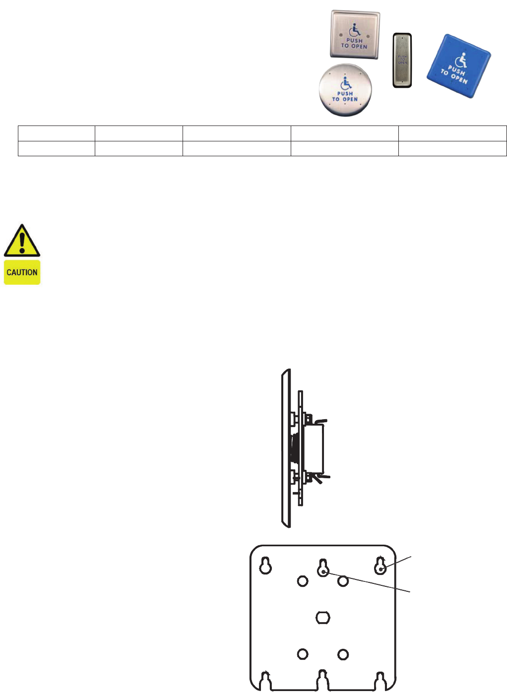
4. Installation
1. Wire the pushplate to the door controller or radio
controlled transmitter using the NO or NC contacts
and common.
2. Finger-tighten the enclosed hex-head screws into
the electrical enclosure.
NOTE: The 6” round and the 4-3/4” square pushplate
there are two different sized screws. The larger screws
(#8) are for the corner locations on 4X4 electrical
type boxes and the two smaller screws (#6) are for the
single-gang electrical type boxes.
3. Place the pushplate holes over the hex-head screws.
Use the enclosed hex key to fully tighten the screws.
4. Test for proper pushplate activation.
NOTE: Pushplates will need an Adapter Ring to use
with the Double Gang Electrical Box.
5. Cleaning Operations
The pushplates are constructed with durable stainless
steel and painted with scuff-resistant coatings. To
clean the plates, use only a damp, non-abrasive cloth.
Regular cleaning with harsh solvents or abrasive
materials may cause deterioration of the paint coating.
Please make the end-user aware of this procedure.
COM
NO
NC
For mounting to 4X4
Electrical Box
For mounting to
Single-Gang Electrical
Box
BACK OF PUSHPLATES
SIDE VIEW
80-9360-0100-000 12/11
