Novatel Wireless GSM0103M Alpine 919 GPRS Modem User Manual Introduction
Novatel Wireless Inc. Alpine 919 GPRS Modem Introduction
UserManual.wiki
>
Novatel Wireless
>
GSM0103M User Manual
Users Manual
Navigation menu
Upload a User Manual
Namespaces
Wiki Guide
HTML
PDF
Info
Views
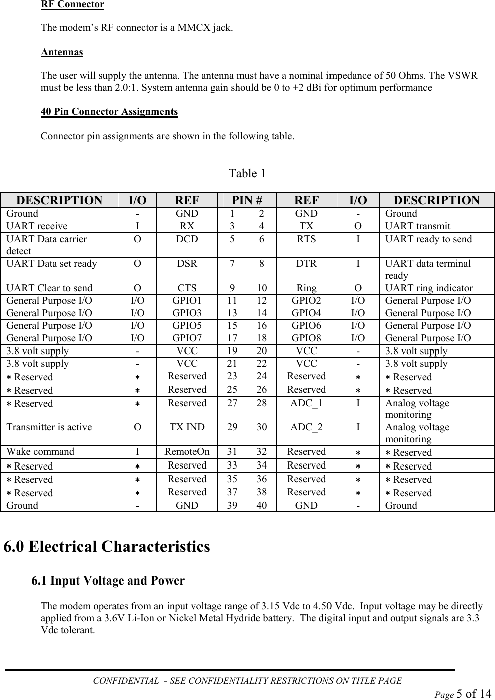
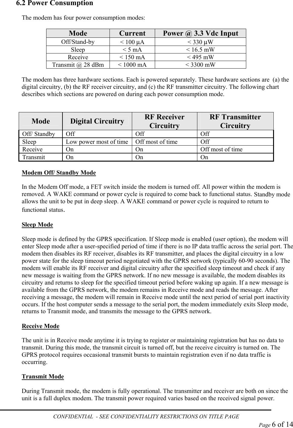
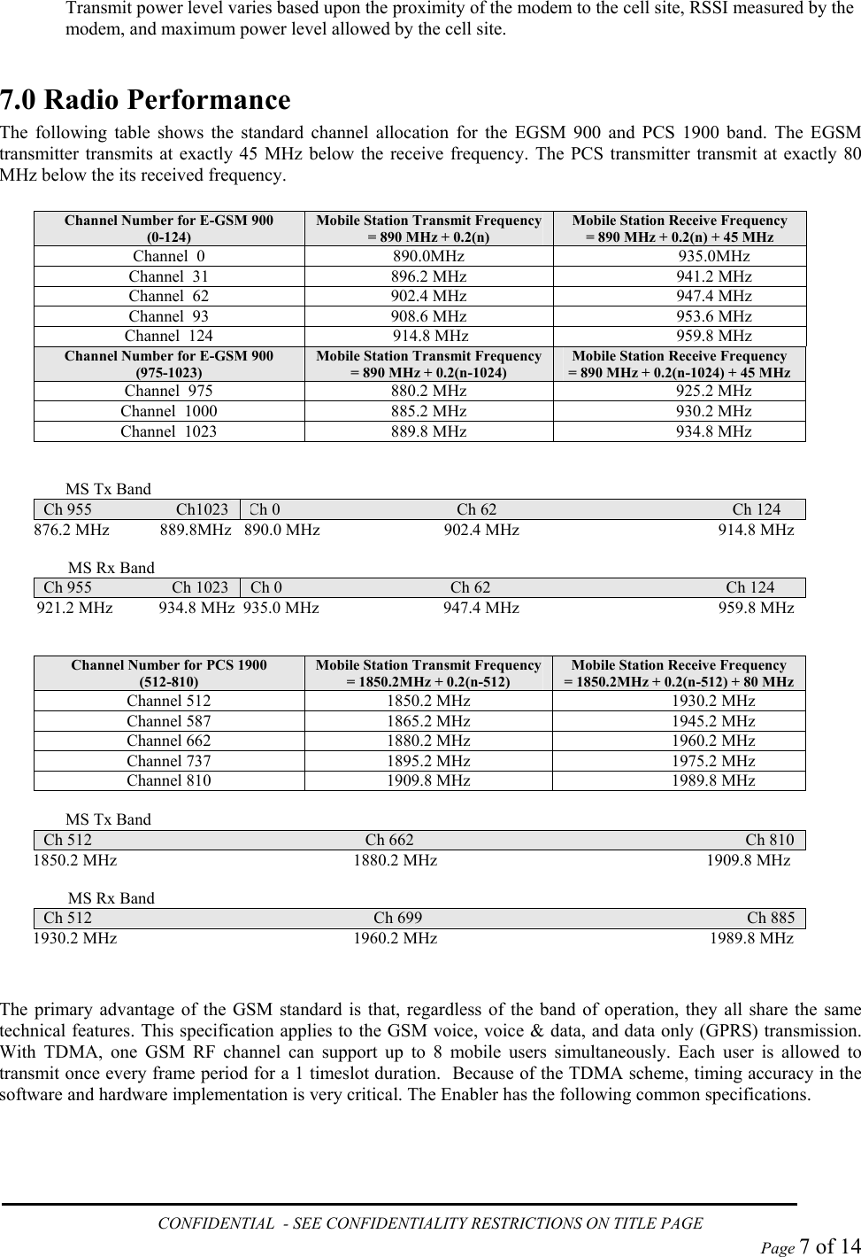
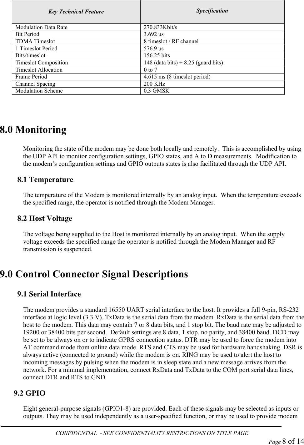
User Manual
Discussion / Help
Navigation