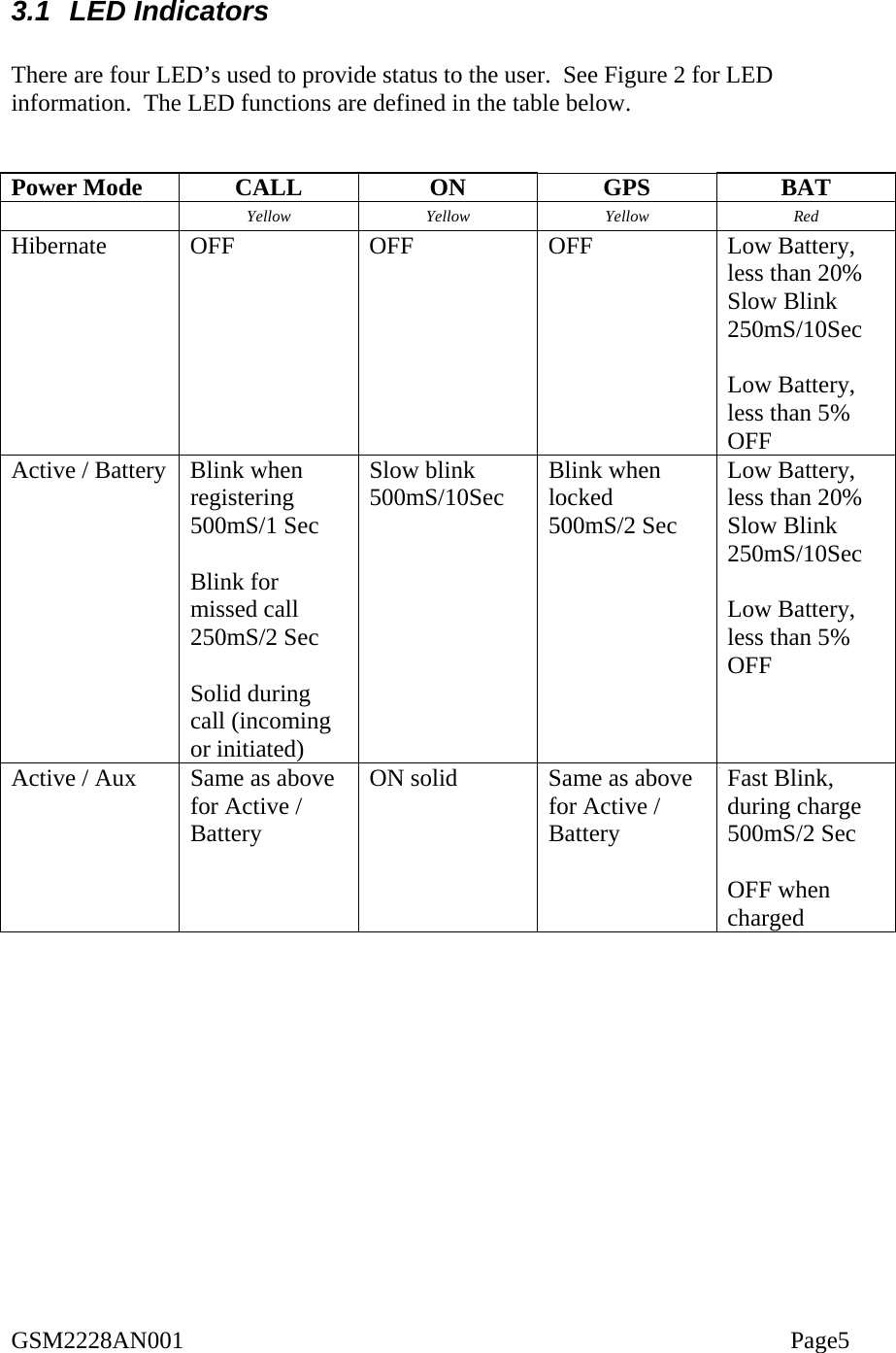
Novatel Wireless GSM2228 Mini MT Vehicle Locator User Manual 1
Novatel Wireless Inc. Mini MT Vehicle Locator 1
UserManual.wiki
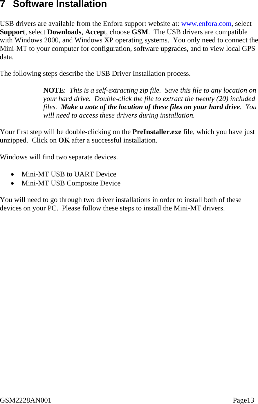
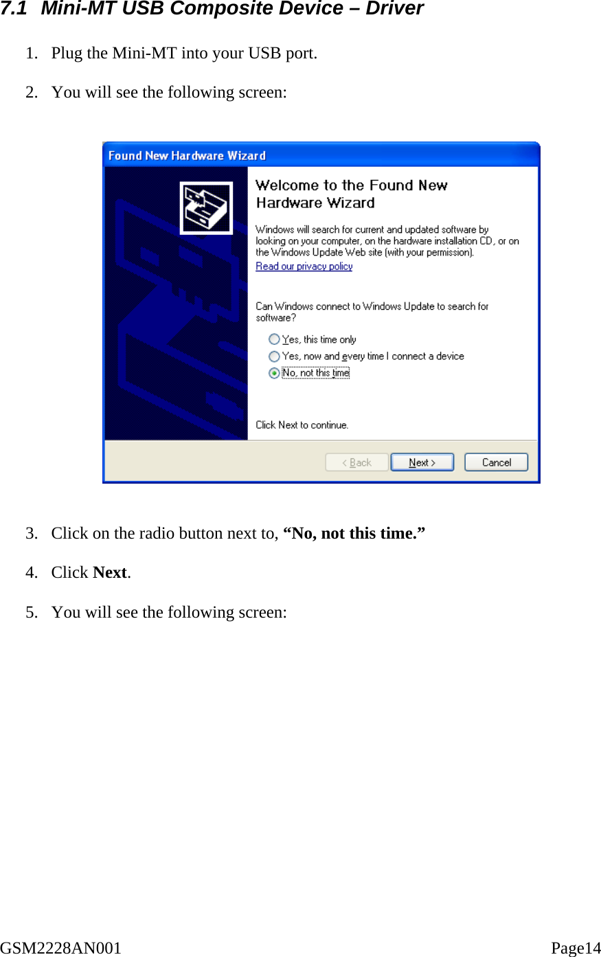
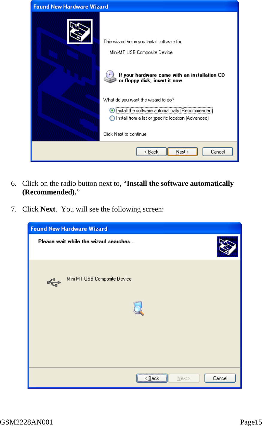
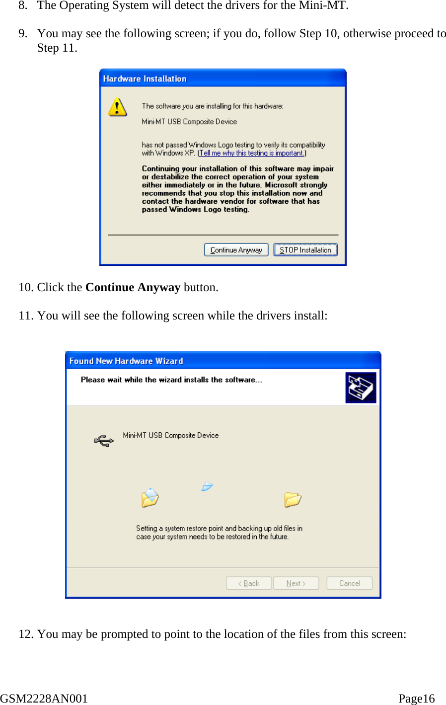
>
Novatel Wireless
>
GSM2228 User Manual
GSM2228 User Manual
Navigation menu
Upload a User Manual
Namespaces
Wiki Guide
HTML
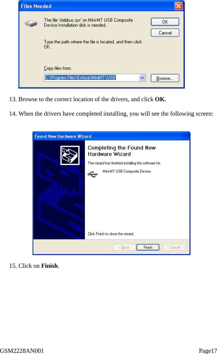
PDF
Info
Views
User Manual
Discussion / Help
Navigation