Novatel Wireless GSM5108 GSM GPRS Transmitter User Manual GSM5108 User Guide
Novatel Wireless Inc. GSM GPRS Transmitter GSM5108 User Guide
UserManual.wiki
>
Novatel Wireless
>
GSM5108 User Manual
GSM5108 User Guide
Navigation menu
Upload a User Manual
Namespaces
Wiki Guide
HTML
PDF
Info
Views
User Manual
Discussion / Help
Navigation
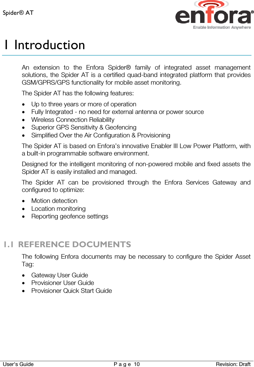

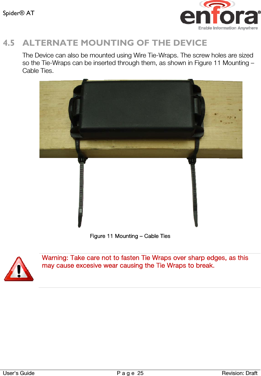
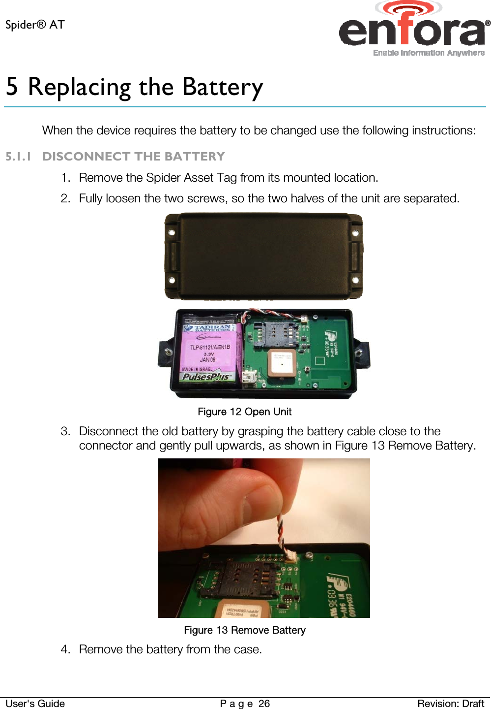
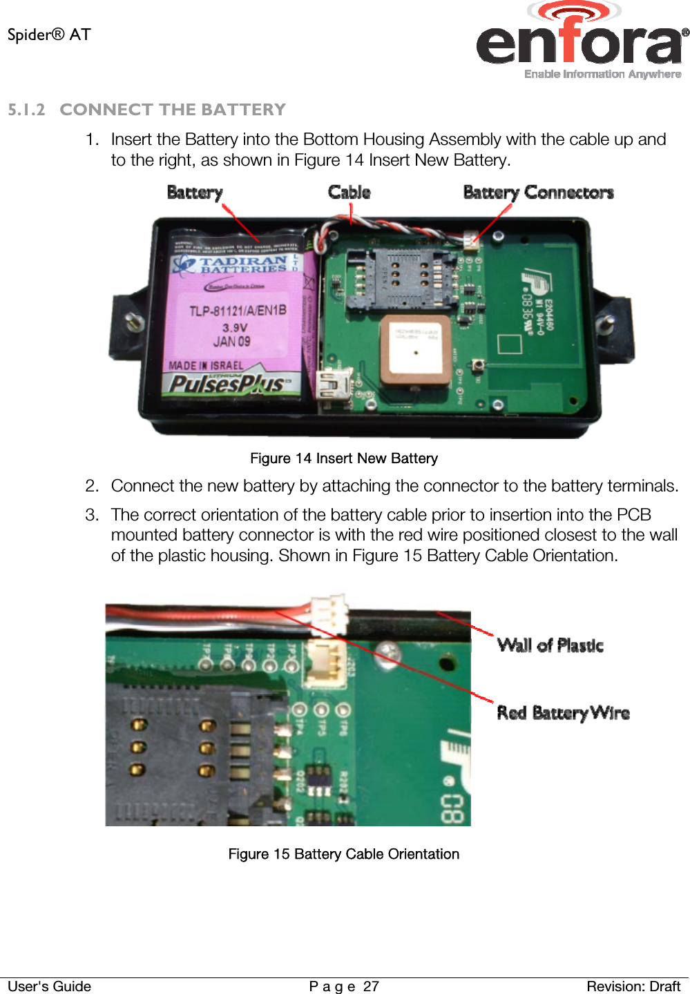
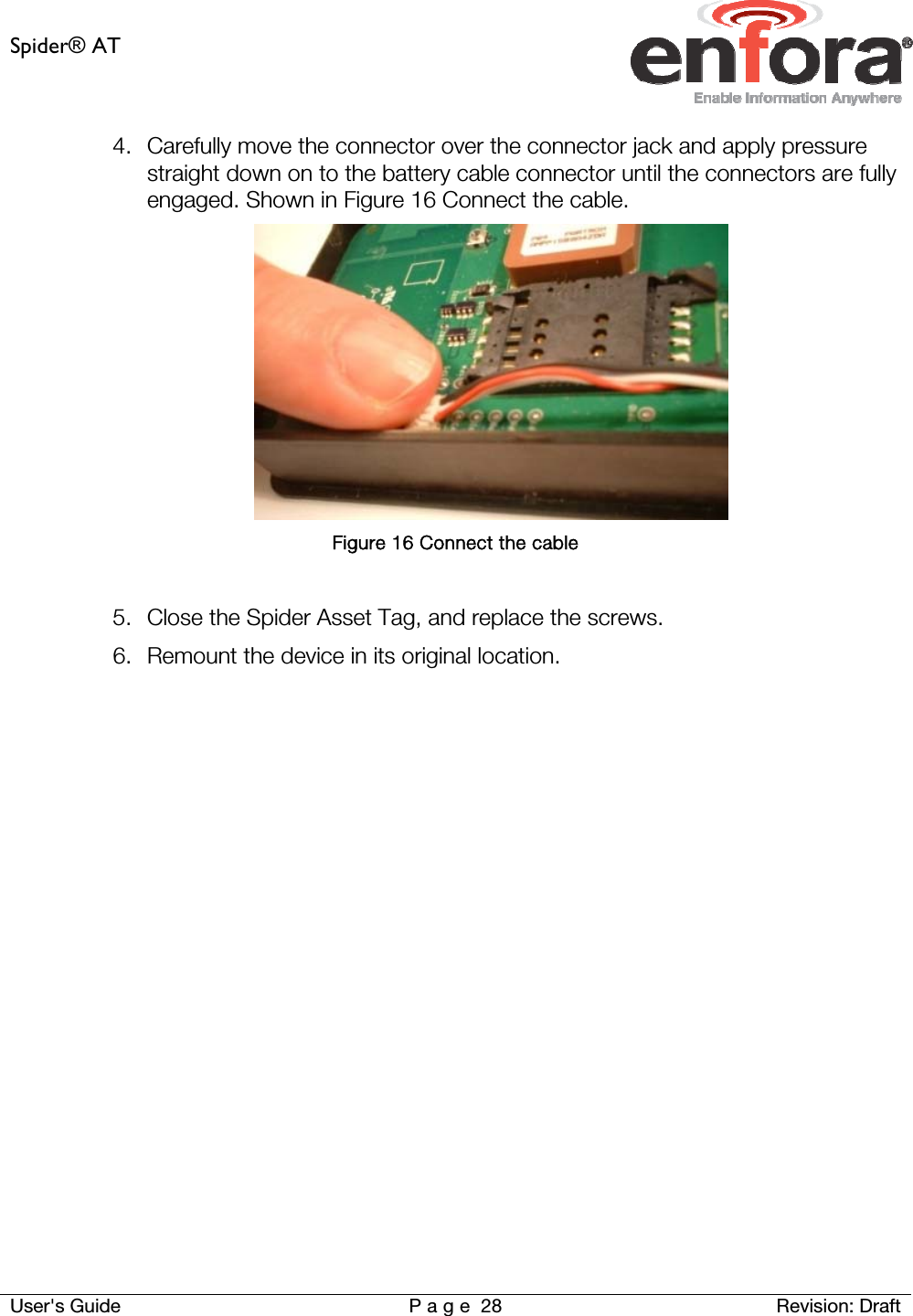
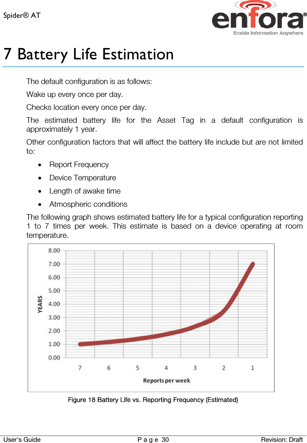
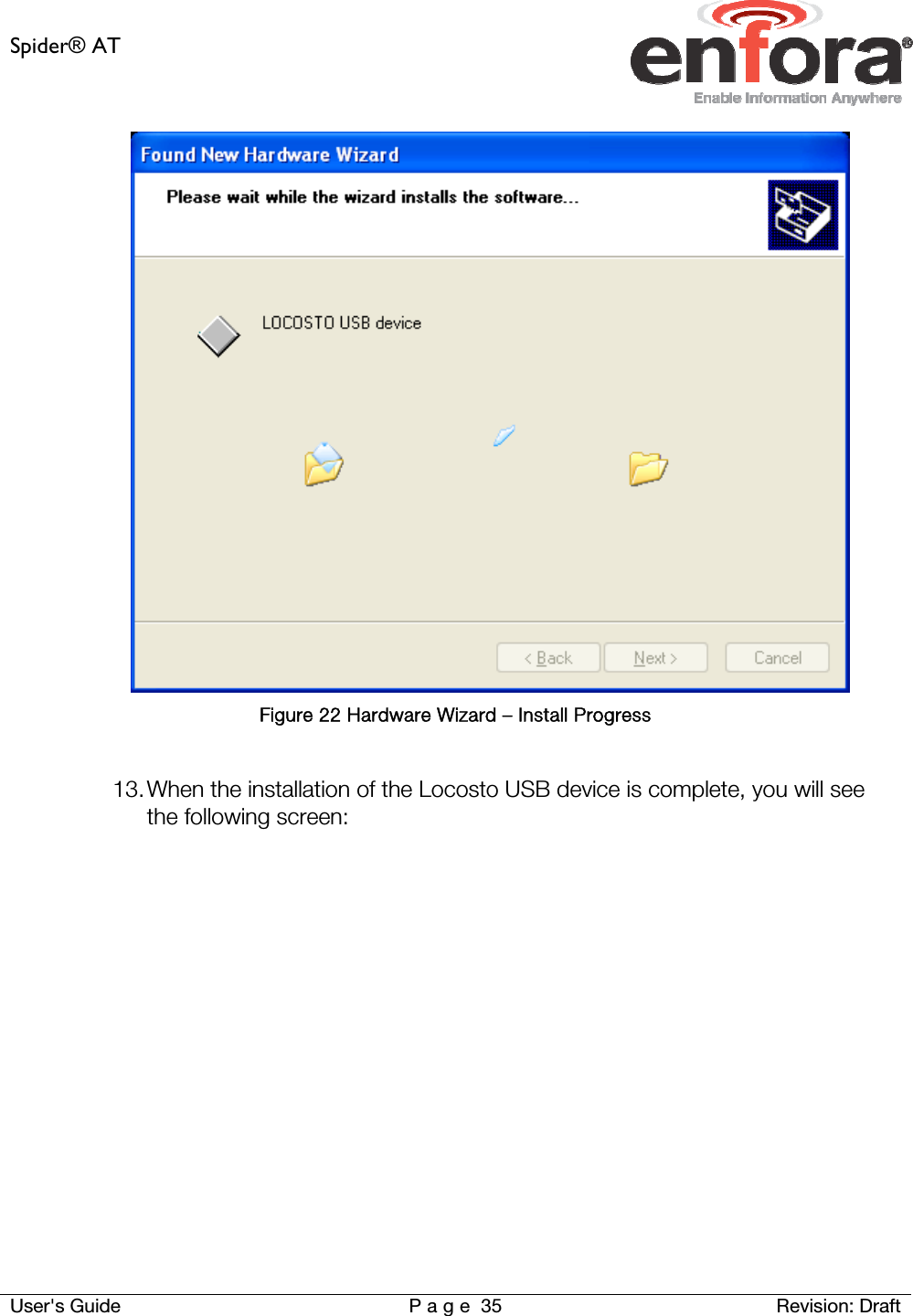
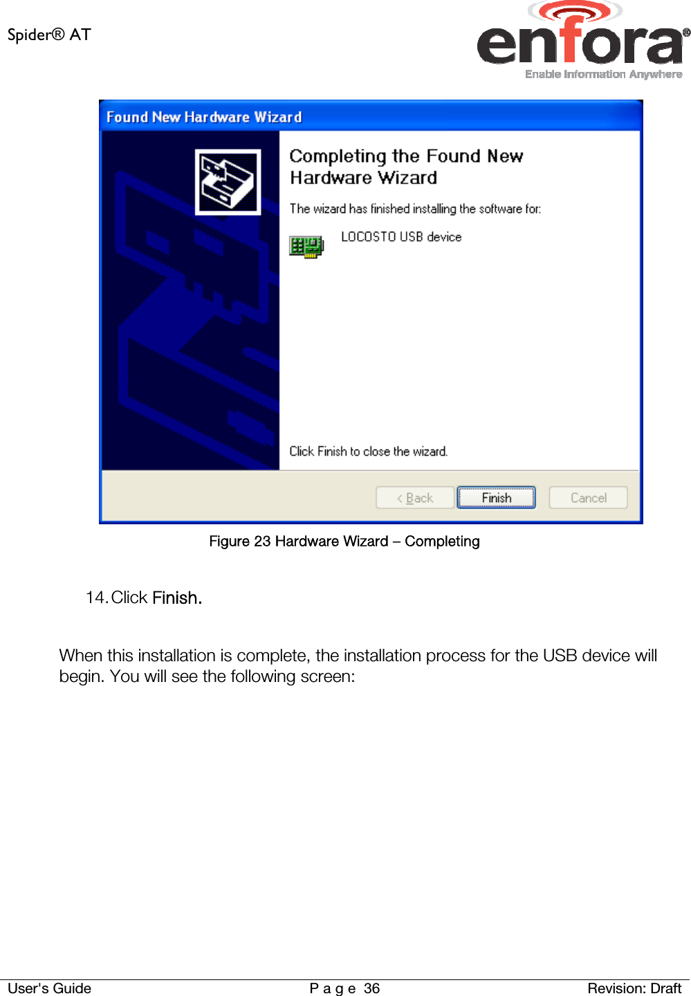
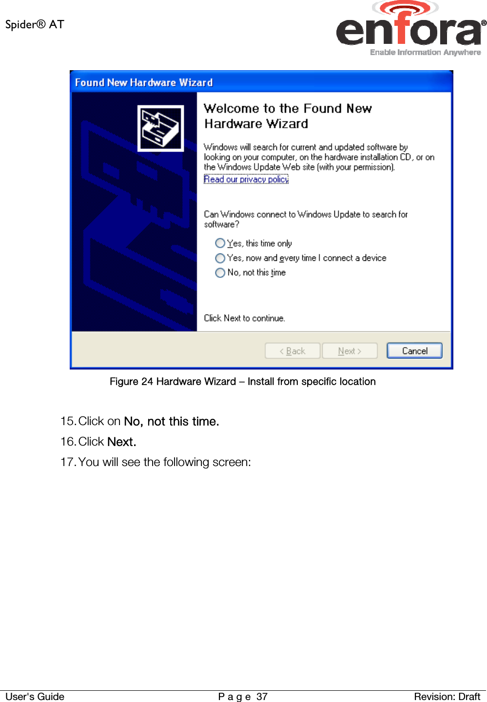
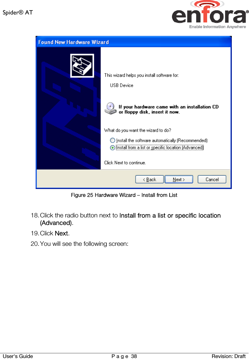
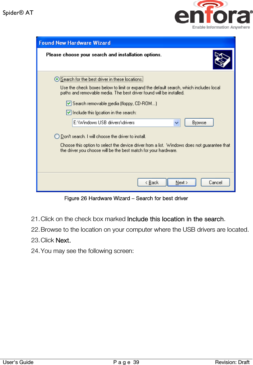
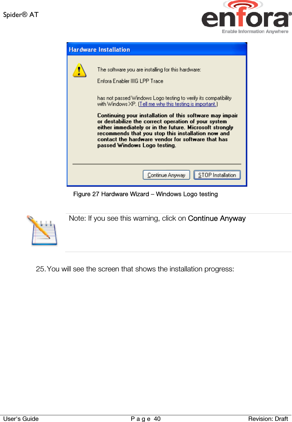
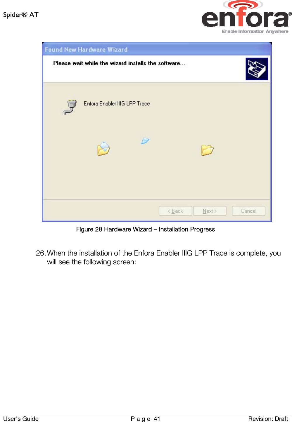
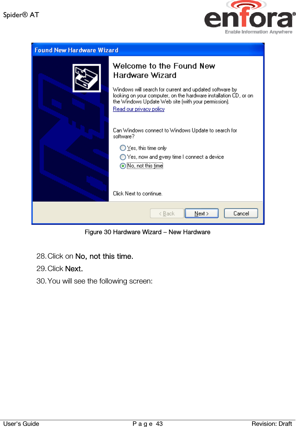
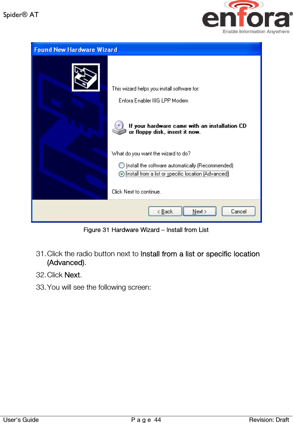
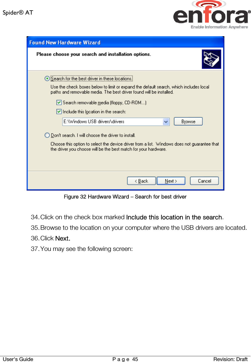
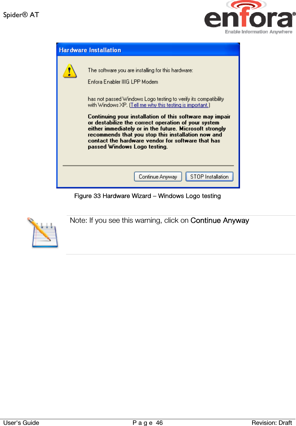
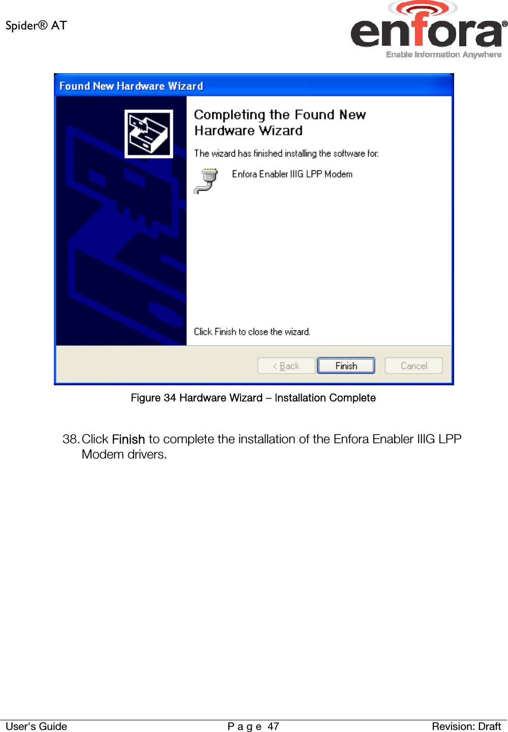
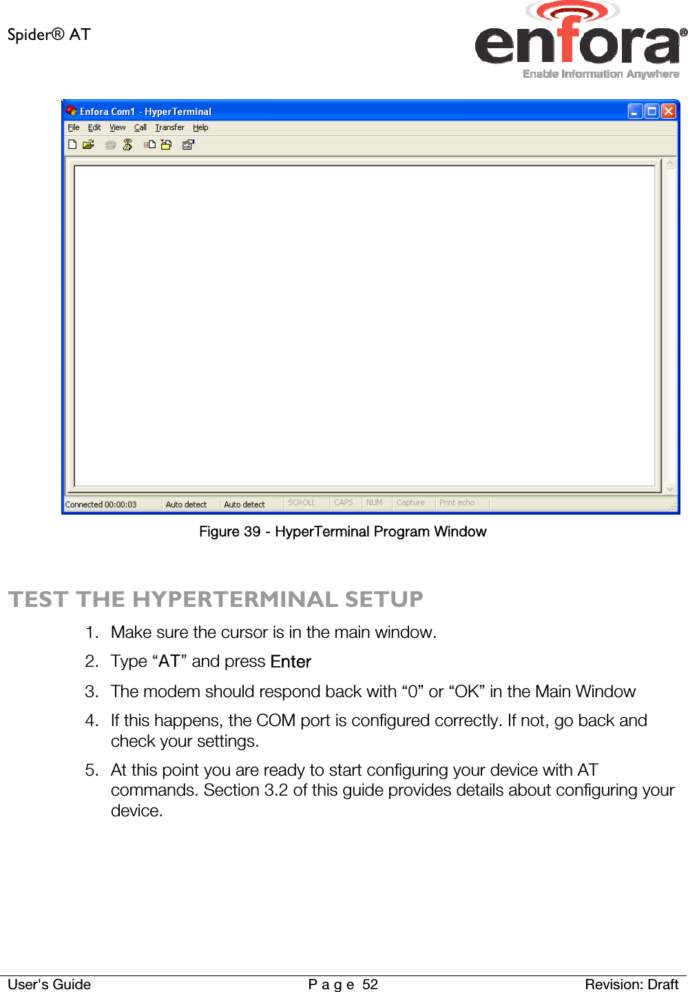
![Spider® AT User's Guide P a g e 20 Revision: Draft 3.2.2 CONFIGURE THE SPIDER ASSET TAG TO USE THE PROVISIONER In order to use the Enfora Provisioner to configure the Spider Asset Tag, you will first need to send communication parameter information to the device with a terminal emulator: Any terminal emulator program such as ProComm or HyperTerminal can be used to send AT commands to the device. Configure the terminal emulator with the following settings: Baud rate is fixed at 115200 No Parity 8 bits 1 stop bit Step-by-step illustrated instructions for setting up HyperTerminal can be found in Section 0 (Appendix C) of this User’s Guide. Below are the basic commands required to establish communication between a device and the Gateway/Provisioner server. AT Command Command Description AT$MDMID="[MDMID]" Choose a unique identifier for your modem ID AT+CGDCONT=1,"IP","[APN]" Configure Carrier APN, where [APN] = APN specific to the SIM used AT$UDPAPI=,[PORT] Configure Server Port, where [PORT] = Port that the Gateway server is monitoring for Modem messages AT$FRIEND=1,1,"[SERVER]",[PORT],3 Configure Server, where [SERVER] = URL or IP address of the server to report to. [PORT] is the TCP port that the device will use for FTP. AT$APIOPT=1,1,0 Configure To use Extended API header and Send the Modem ID and the Param2 values with every report. AT$AREG=2 Auto Registration Mode Set modem to automatically attempt a PDP activation on power-up. AT&W Save these settings on the device.](https://usermanual.wiki/Novatel-Wireless/GSM5108/User-Guide-1076679-Page-21.png)