Novatel Wireless NRM-EU870D Mini-PCI Licensed Modular Transmitter User Manual User installation guide fcc
Novatel Wireless, Inc. Mini-PCI Licensed Modular Transmitter User installation guide fcc
Revised Manual

PCI Express Mini-card
Integration & Design Guide
Version 2.1

2
Novatel Wireless
Revision 1
Notice: Restricted Proprietary Information and subject to the confidentiality restrictions contained
in any applicable non-disclosure agreement.
© Copyright Novatel Wireless, Inc. (2006)
The information contained in this document is the exclusive property of Novatel Wireless, Inc. All
rights reserved. Unauthorized reproduction of this manual in any form without the expressed
written approval of Novatel Wireless, Inc. is strictly prohibited. This manual may not, in whole or in
part, be copied, reproduced, translated, or reduced to any electronic or magnetic storage medium
without the written consent of a duly authorized officer of Novatel Wireless, Inc.
The information contained in this document is subject to change without notice and should not be
construed as a commitment by Novatel Wireless, Inc. unless such commitment is expressly given
in a covering document.
Novatel Wireless, Inc. makes no warranties, either expressed or implied, regarding this
document, its merchantability, or its fitness, for any particular purpose.
Legal Disclaimer
This document and the information contained in the PCI Express Mini-card Integration &
Design Guide (together, the “Information”) is provided to you by Novatel Wireless for
informational purposes only.
Novatel Wireless is providing the Information because Novatel Wireless believes the Integration
and Design Guidelines may be useful. The Information is provided on the condition that you will

3
Novatel Wireless
Revision 1
be responsible for making your own assessments of the information and are advised to verify all
representations, statements and information before using or relying upon any of the Information.
Although Novatel Wireless believes it has exercised reasonable care in providing the Information,
Novatel Wireless does not warrant the accuracy of the Information and is not responsible for any
damages arising from its use or reliance upon the Information. You further understand and agree
that Novatel Wireless in no way represents, and you in no way rely on a belief, that Novatel
Wireless is providing the information in accordance with any standard or service (routine,
customary or otherwise) related to the consulting, services, hardware or software industries.
NOVATEL WIRELESS DOES NOT WARRANT THAT THE INFORMATION IS ERROR-FREE.
NOVATEL WIRELESS IS PROVIDING THE INFORMATION TO YOU "AS IS" AND "WITH ALL
FAULTS." NOVATEL WIRELESS DOES NOT WARRANT, BY VIRTUE OF THIS DOCUMENT,
OR BY ANY COURSE OF PERFORMANCE, COURSE OF DEALING, USAGE OF TRADE OR
ANY COLLATERAL DOCUMENT HEREUNDER OR OTHERWISE, AND HEREBY EXPRESSLY
DISCLAIMS, ANY REPRESENTATION OR WARRANTY OF ANY KIND WITH RESPECT TO
THE INFORMATION, INCLUDING, WITHOUT LIMITATION, ANY REPRESENTATION OR
WARRANTY OF DESIGN, PERFORMANCE, MERCHANTABILITY, FITNESS FOR A
PARTICULAR PURPOSE OR NON-INFRINGEMENT, OR ANY REPRESENTATION OR
WARRANTY THAT THE INFORMATION IS APPLICABLE TO OR INTEROPERABLE WITH ANY
SYSTEM, DATA, HARDWARE OR SOFTWARE OF ANY KIND.
NOVATEL WIRELESS DISCLAIMS AND IN NO EVENT SHALL BE LIABLE FOR ANY LOSSES
OR DAMAGES OF ANY KIND, WHETHER DIRECT, INDIRECT, INCIDENTAL,
CONSEQUENTIAL, PUNITIVE, SPECIAL OR EXEMPLARY, INCLUDING, WITHOUT
LIMITATION, DAMAGES FOR LOSS OF BUSINESS PROFITS, BUSINESS INTERRUPTION,
LOSS OF BUSINESS INFORMATION, LOSS OF GOODWILL, COVER, TORTIOUS CONDUCT
OR OTHER PECUNIARY LOSS, ARISING OUT OF OR IN ANY WAY RELATED TO THE
PROVISION, NON-PROVISION, USE OR NON-USE OF THE INFORMATION, EVEN IF YOU
HAVE BEEN ADVISED OF THE POSSIBILITY OF SUCH LOSSES OR DAMAGES.

4
Novatel Wireless
Revision 1
Table of Contents
Reference Documents ................................................................................................................ 7
PCI Express Mini Card References............................................................................... 7
3GPP References ......................................................................................................... 7
Notices......................................................................................................................................... 9
Safety Warning ............................................................................................................. 9
Federal Communications Commission Notice (FCC—United States) ......................... 10
Radio Frequency Exposure Requirements.................................................................. 10
Compliance & Certification Requirements................................................................... 11
Windows Platforms ..................................................................................................... 12
Technical Support Contacts ........................................................................................ 12
Getting Started.......................................................................................................................... 13
General ....................................................................................................................... 13
Setting Up ................................................................................................................... 13
Product Overview ..................................................................................................................... 20
HSDPA Module Overview ........................................................................................... 20
Network Overview .................................................................................................. 21
Application Software Overview.................................................................................... 21
Device Specifications............................................................................................................... 23
PCI Express Mini Card................................................................................................ 23
Interface Specification................................................................................................. 27
Environmental ............................................................................................................. 31
Integrator Design Elements: Antenna, SIM & SMBus ........................................................... 32
Antenna ...................................................................................................................... 32
SIM Design Guidelines................................................................................................ 35
SM Bus Design Guidelines ......................................................................................... 42
MobiLink Connection Manager................................................................................................ 44
GENERAL FEATURES............................................................................................... 44
MOBILINK™ FEATURES ........................................................................................... 48
Appendix C - Regulatory Approval and Compliance ............................................................. 73
FCC (Federal Communication Commission)............................................................... 73
CE (Conformance European)...................................................................................... 74
Appendix D - Reference Parts Specifications......................................................................... 76
Appendix I - Glossary............................................................................................................... 80
Table of Figures
Figure 2: EU860D/EU870D Module.................................................................................. 24
Figure 3: EU860D/EU870D Module.................................................................................. 25
Figure 4: PCIe Minicard Module Envelope........................................................................ 26
Figure 5: Total Radiated Power ........................................................................................ 33
Figure 6: Plug-in SIM (shown from contact side)............................................................... 35
Figure 7: IO driver and pull-ups......................................................................................... 37
Figure 8: Reference circuit................................................................................................ 38
Figure 9: SM Pull-up Configuration ................................................................................... 43

5
Novatel Wireless
Revision 1
Figure 10: Main MobiLink Display....................................................................................... 45
Figure 11: Skin Design........................................................................................................ 46
Figure 12: On-Line Help...................................................................................................... 47
Figure 13: Status Indication ................................................................................................ 48
Figure 14: 3G Wireless View .............................................................................................. 49
Figure 15: WiFi View........................................................................................................... 50
Figure 16: HotSpot Activation ............................................................................................. 51
Figure 17: Network Connection........................................................................................... 51
Figure 18: Ethernet View .................................................................................................... 52
Figure 19: Connection Button ............................................................................................. 53
Figure 20: 3G Profiles......................................................................................................... 54
Figure 21: Profile Settings................................................................................................... 55
Figure 22: Different Tab Settngs ......................................................................................... 55
Figure 23: Profile Wizard Step 1 ......................................................................................... 56
Figure 24: Profile Wizard Step #2 ....................................................................................... 57
Figure 25: Profile Wizard Step #3 ....................................................................................... 57
Figure 26: General Tab....................................................................................................... 58
Figure 27: Mobile Tab......................................................................................................... 59
Figure 28: WiFi Tab ............................................................................................................ 60
Figure 29: WAP Window..................................................................................................... 60
Figure 30: Ethernet Tab...................................................................................................... 61
Figure 31: AP Window ........................................................................................................ 61
Figure 32: CDMA ................................................................................................................ 62
Figure 33: UMTS/HSDPA ................................................................................................... 62
Figure 34: Report Log......................................................................................................... 63
Figure 35: Desktop Transparency....................................................................................... 64
Figure 36: About Dialogue .................................................................................................. 65
Figure 37: Enter PUK.......................................................................................................... 65
Figure 38: Configuration Menu............................................................................................ 65
Figure 39: Quick Access Button Default Functions ............................................................. 66
Figure 40: MobiLink SMS Client.......................................................................................... 67
Figure 41: Compose Message............................................................................................ 69
Figure 42: Address Book .................................................................................................... 71
Figure 43: Select Group Contacts....................................................................................... 72
Figure 44: RF Connector .................................................................................................... 76
Figure 45: Mini PCI Express Connector.............................................................................. 77
Table of Tables
EU860D/870D & E725 Environmental Specification ................................................................... 31
GSM-1900 Test Frequencies ...................................................................................................... 33
Table 1: SIM interface signals..................................................................................................... 36
Table 2: VCC electrical requirements.......................................................................................... 36
Table 3: RST electrical requirements .......................................................................................... 36
Table 4: CLK electrical requirements .......................................................................................... 37
Table 5: IO electrical requirements .............................................................................................37
Status Indication ......................................................................................................................... 48
3G Indicators............................................................................................................................... 52
Menu Subjects ............................................................................................................................ 53
General Tab Features................................................................................................................. 58
Mobile Tab Features ................................................................................................................... 59
Identity Properties ....................................................................................................................... 62
Report Values ............................................................................................................................. 63

6
Novatel Wireless
Revision 1
Mailbox List................................................................................................................................. 67
Fields List.................................................................................................................................... 68
Tool Bar Button........................................................................................................................... 69
Destination Addresses ................................................................................................................ 70
Address Books............................................................................................................................ 71
R&TTE ........................................................................................................................................ 74
GSM/GPRS European Regulations ............................................................................................ 75

7
Novatel Wireless
Revision 1
Reference Documents
PCI Express Mini Card References
PCI Express Mini Card Electromehcanical Specification Revision 1.0 June 2, 2003
PCI Express Card Electromechancil Specification revision 1.1 March 28th 2005
SMBus Specification, Revision 2.0
The I2C-BUS SPECIFICATION Version 2.1 January 2000
3GPP References
The following documents contain provisions which, through reference in this text, constitute
provisions of the present document.
References are either specific (identified by date of publication, edition number, version
number, etc.) or non-specific.
For a specific reference, subsequent revisions do not apply.
For a non-specific reference, the latest version applies. In the case of a reference to a 3GPP
document (including a GSM document), a non-specific reference implicitly refers to the
latest version of that document in the same Release as the present document.
[1] Void.
[2] 3GPP TS 23.038: "Alphabets and language-specific information".
[3] 3GPP TS 23.040: "Technical realization of the Short Message Service (SMS) ".
[4] 3GPP TS 23.041: "Technical realization of the Cell Broadcast Service (CBS)".
[5] 3GPP TS 24.008: "Mobile Radio Interface Layer 3 specification; Core Network
Protocols; Stage 3".
[6] 3GPP TS 24.011: "Short Message Service (SMS) support on mobile radio interface".
[7] 3GPP TS 24.012: "Cell Broadcast Service (CBS) support on the mobile radio
interface".
[8] 3GPP TS 27.001: "General on Terminal Adaptation Functions (TAF) for Mobile
Stations (MS)".
[9] 3GPP TS 27.007: "AT command set for User Equipment (UE)".
[10] 3GPP TS 51.011: "Specification of the Subscriber Identity Module - Mobile
Equipment (SIM - ME) interface".
[11] ITU-T Recommendation V.25ter: "Serial asynchronous automatic dialing and
control".
[12] ITU-T Recommendation V.24: "List of definitions for interchange circuits between
data terminal equipment (DTE) and data circuit-terminating equipment (DCE)".
[13] ITU-T Recommendation E.164: "The international public telecommunication
numbering plan".

8
Novatel Wireless
Revision 1
[14] ITU-T Recommendation E.163: "Numbering plan for the international telephone
service".
[15] 3GPP TR 21.905: "Vocabulary for 3GPP Specifications".
[16] 3GPP TS 31.102: "Characteristics of the USIM application.

9
Novatel Wireless
Revision 1
Notices
Safety Warning
Neither the E725 nor EU860D / EU870D products may be used in an environment where radio
frequency equipment is prohibited or restricted in its use. This includes aircraft/airports, hospitals,
and other sensitive electronic areas.
Do not operate RF devices in an environment that may be susceptible to radio interference
resulting in danger, specifically:
• Areas where prohibited by the law
Follow any special rules and regulations and obey all signs and notices. Always
turn off the host device when instructed to do so, or when you suspect that it may
cause interference or danger.
• Where explosive atmospheres may be present
Do not operate your modem in any area where a potentially explosive
atmosphere may exist. Sparks in such areas could cause an explosion or fire
resulting in bodily injury or even death. Be aware and comply with all signs and
instructions.
• Users are advised not to operate the modem while at a refueling point or service
station.
Users are reminded to observe restrictions on the use of radio equipment in fuel
depots (fuel storage and distribution areas), chemical plants or where blasting
operations are in progress.
• Areas with a potentially explosive atmosphere are often but not always clearly
marked.
Potential locations can include gas stations, below deck on boats, chemical
transfer or storage facilities, vehicles using liquefied petroleum gas (such as
propane or butane), areas where the air contains chemicals or particles, such as
grain, dust or metal powders, and any other area where you would normally be
advised to turn off your vehicle engine.
• Near Medical and life support equipment
Do not operate your modem in any area where medical equipment, or life support
equipment may be located, or near any equipment that may be susceptible to
any form of radio interference. In such areas, the host communications device
must be turned off. The modem may transmit signals that could interfere with this
equipment.
• On an aircraft, either on the ground or airborne
In addition to FAA requirements, many airline regulations state that you must
suspend wireless operations before boarding an airplane. Please ensure that the
host device is turned off and your modem is removed from the card slot prior to
boarding aircraft in order to comply with these regulations. The modem can
transmit signals that could interfere with various onboard systems and controls.
• While operating a vehicle
The driver or operator of any vehicle should not operate a wireless data device.
Doing so will detract from the driver or operator's control and operation of that

10
Novatel Wireless
Revision 1
vehicle. In some countries, operating such communication devices while in
control of a vehicle is an offence.
Under extended operation the EU870D and EU860D modem will generate a noticeable amount of
heat. Like all PC Cards, the modem generates heat during normal operation and will be heated
by the host computer. For this reason it is recommended that after extended periods of operation,
prior to removal and handling, you allow the modem to cool down.
Federal Communications Commission Notice (FCC—United States)
This equipment has been tested and found to comply with the limits for a Class B digital device,
pursuant to Part 15 of the FCC Rules. These limits are designed to provide reasonable protection
against harmful interference in a residential installation. This equipment generates, uses and can
radiate radio frequency energy and, if not installed and used in accordance with the instructions,
may cause harmful interference to radio communications.
However, there is no guarantee that interference will not occur in a particular installation. If this
equipment does cause harmful interference to radio or television reception, which can be
determined by turning the equipment off and on, the user is encouraged to try to correct the
interference by one or more of the following measures:
• Reorient or relocate the receiving antenna.
• Increase the separation between the equipment and receiver.
• Connect the equipment into an outlet on a circuit different from that to which the receiver is
connected.
• Contact your service provider for help.
Warning: Changes or modifications made to this equipment not expressly approved by Novatel
Wireless may void the FCC authorization to operate this equipment.
This device complies with Part 15 of the FCC Rules and with RSS-210 of Industry Canada.
Operation is subject to the following two conditions:
(1) this device may not cause harmful interference, and
(2) this device must accept any interference received, including interference that may
cause undesired operation.
Radio Frequency Exposure Requirements
In general, for the United States market, the embedded modules are treated as “mobile devices”
as per FCC CFR47 paragraph 2.1091. A mobile device is defined as “a transmitting device
designed to be used in other than fixed locations and to generally be used in such a way that a
separation distance of at least 20 cm is normally maintained between the transmitter’s radiating
structure(s) and the body of the user or nearby persons.”
CE (Conformité Européenne or European Conformity)
This module will be tested to and conforms to the regulatory requirements of the European Union
and has attained CE Marking. The CE Mark is a conformity marking consisting of the letters "CE".

11
Novatel Wireless
Revision 1
The CE Mark applies to products regulated by certain European health, safety and environmental
protection legislation. The CE Mark is obligatory for products it applies to: the manufacturer
affixes the marking in order to be allowed to sell his product in the European market.
Radiocommunications and Telecommunications Terminal Equipment Industries (R&TTE)
This is mandatory for European operation and the directive applies to products using the radio
frequency spectrum and all equipment attached to public telecommunications networks.
This product conforms to the essential requirements of the Radiocommunications and
Telecommunications Terminal Equipment Directive (R&TTE) 1999/5/EC with respect to the
following articles:
• 3.1a Safety
• 3.1b EMC
• 3.2 Spectrum
A notified body will determine that this device has properly demonstrated that the requirements of
the directive have been met and has issued a favorable certificate of expert opinion. As such the
device will bear the notified body number (TBD) after the CE Mark.
Compliance & Certification Requirements
PCS Type Certification Review Board (PTCRB)
PTCRB Certification is mandated and the product is technically evaluated to meet the minimum
requirements for registration on the PTCRB Operators’ networks. The purpose of the PTCRB is to
provide the framework within which GSM Mobile Equipment (ME) Type Certification can take
place for members of the PTCRB. The PTCRB process is recommended for all Manufacturers
who wish to have their products operating within the areas served by the PTCRB Operators. This
includes but is not limited to determination of the test specifications and methods to implement
the Type Certification process for GSM Mobile Equipment.
PTCRB type certification will be based on GSM and OMA (Open Mobile Alliance) Specifications
with modifications per North American Standards and additional requirements from FCC rules,
and any other government agency that may have jurisdiction and or competence in the matter.
Additions to the PTCRB Specifications will be developed by the GSM operators. The additions
will be limited to MS-related features. The PTCRB document NAPRD 03 (Permanent Reference
Document) will be modified to include references to the above specifications once they are written
and accepted by majority of the review board.
To learn more about device certifications, please visit the PTCRB Website. You must sign up as
a member to gain access

12
Novatel Wireless
Revision 1
Global Certification Forum (GCF),
The Global Certification Forum (GCF) is an independent organization with a wide-ranging
membership of operators, equipment manufacturers and other interested parties. The actions of
the Forum are actively supported by key staff from the Association Technical Projects operation
and by the Association Executive Management Committee.
GCF is recommended but not mandatory for attachment to the European network. It is a
partnership between network operators and terminal manufacturers and allows independent
interoperability validation of the 2G and 3G mobile wireless terminal. GCF is typically required for
formal carrier technical acceptance of the mobile wireless terminal.
Membership of GCF is entirely voluntary. Full GCF membership is open to mobile terminal
manufacturers and network operators. Other interested members of the mobile wireless
community, including test laboratories and test equipment manufacturers, may participate in GCF
as observers.
The current membership includes almost 150 network operators worldwide, more than 35 leading
terminal manufacturers and over 50 test equipment manufactures. Members decide the
organization and administration of the forum at regular Steering Group meetings. Technical
issues associated with testing new terminals and features are reviewed at regular Agreement
Group meetings by manufacturers, test laboratories and other observers.
To learn more about device certifications, please visit the GCF Website. The website identifies
manufacture, terminal names and the date which the terminal was certified. You must sign up as
a member to gain full access.
Windows Platforms
The Phoenix API will interface with your top level applications and provide the abstraction of the
module specifics to the upper applications. Please refer to the Phoenix API Interface Appendix for
details.
Please refer to the MobiLink Phoenix SDK chapter for details on developing applications and
communicating with the modem on Windows platforms.
Technical Support Contacts
WWW: http://www.nvtl.com/support/index.html
Email: support@novatelwireless.com

13
Novatel Wireless
Revision 1
Getting Started
General
The purpose of this document is to provide advance design and integration information to assist
in the integration planning and evaluation of Novatel Wireless PCI Express Mini-cards. This
document is intended to specify key components of the integration tools available for the Novatel
Wireless line of PCI Express Mini-cards.
The E725, EU860D & EU870D are Novatel Wireless’ versatile modules that add WWAN
capability to other devices. They were developed to be integrated into other devices based on the
PCI Express Mini-card specification 1.0.
The E725, EU860D and EU870D will work with all Windows driven laptops given the drivers are
properly installed. When MobiLink™ is installed on a Windows OS system it will automatically
include the drivers necessary to communicate with the PCI Express Mini-card. MobiLink™ is
Novatel’s Windows application manager for the PCI Express Mini Card. MobiLink provides an
easy interface to make a data connection, change operating parameters, and view alerts such as
SMS or signal strength indicator. However, anyone can still install the drivers manually. In
addition, once the drivers are installed, following the Phoenix Client API functions, anyone could
develop their Client side software manager to interact with the PCI Express Mini-card.
When using any of these devices, EU860D, EU870D or the E725, activation is required for the
device to be allowed on the operator’s network. For example, Sprint requires the customer to run
IOTA (Internet Over-The-Air) provisioning to prepare the device to work on the wireless network.
Please refer to the Customer Configuration section on provisioning with IOTA for assistance.
The EU860D and EU870D require a valid SIM card before it can be used on the operator’s
wireless network. Please refer to the Customer Configuration section on PRI for further
information.
Setting Up
The purpose of this section is to assist in the initial connection and provide the reader with
instructions for how to setup and establish communication with the Novatel Wireless line of PCI
Express Mini-card. The following setup guide refers to an HSDPA Mini-card for convenience of
the set up discussion. The same setup is valid for both the HSDPA and EVDO Mini-cards.
Setting up and establishing communication with the Novatel Wireless PCI Express Mini-card
involves:
o Connecting the PCI Express Mini-card to the computer and the Development Board.
o Establishing communication with the PCI Express Mini-card and determining the
computer COM Port being used.
o Setting up and using the HyperTerminal program to communicate with the Mini-card
CONNECTING THE PCI EXPRESS MINI-CARD TO THE COMPUTER AND THE
DEVELOPMENT BOARD
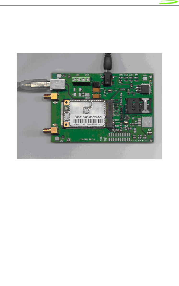
Insert the PCI Express Mini-card into the Development Board (Novatel Wireless Part # 01017568)
by sliding the connector end of the Mini-card into the Molex connector. Push down on the
opposite end of the Mini-card until the 2 black locking tabs snap into place.
14
Novatel Wireless
Revision 1
Connect an A to B USB cable from the Development Board to the computer USB port.
When ready to power up the modem, plug the AC wall adaptor that came with the Development
board into the wall.
If desired, the Development Board can be powered by a bench top power supply. See the
Hardware Development Kit section for more details.
Figure 1 – Modem Interface Board and Cables
ESTABLISHING COMMUNICATION WITH THE PCI EXPRESS MINI-CARD AND
DETERMINING THE COMPUTER COM PORT BEING USED
Once the modem is powered up and connected, you should hear a sound indicating the computer
has recognized the modem.
Determining the Computer’s Active Primary COM Port
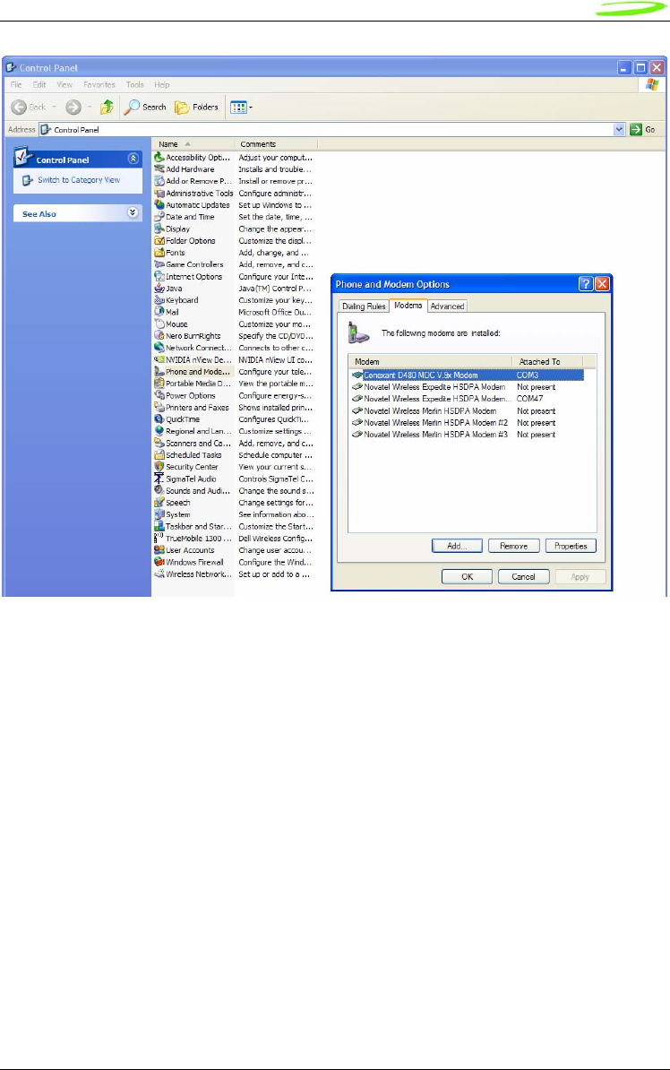
To verify the computer’s recognition of the modem and to verify which Primary COM Port it is
connected to, navigate to Start\Control Panel\Phone and Modem Options and then click on the
Modems tab within the Phone and Modem Options window. Refer to Figure 2 below.
15
Novatel Wireless
Revision 1
Figure 2 – Phone and Modems Options Window
Look for the Novatel Wireless Merlin HSDPA Modem item on the list. To the right of this item in
the ‘Attached To’ column, you will see a COM port number - make a note of this Primary COM
Port Number. If you do not see any COM No. for this item and you only see “Not Present”, then
this indicates that the modem is not being recognized and is not attached to a COM Port on the
computer. In this case, make sure the USB and power cable are properly connected at both
ends. If the modem has properly booted up, with no SIM in the SIM holder, the WAN LED on the
Development Board should be blinking at a steady rate. If there is a SIM in the SIM Holder, the
LED will be solid green.
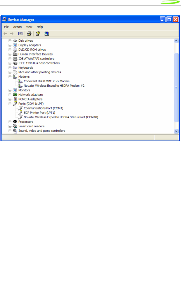
Determining the Computer’s Active Secondary or Status COM Port
To verify which Secondary, or Status COM Port the modem is connected to, navigate to
Start\Control Panel\System. After you have double-clicked on the System Icon, click on the
Hardware Tab within the System Properties window. Now click on the Device Manager tab. In
the Device Manager window, click on the “+” beside Modems to expand this item. You should
now see the Novatel Wireless Expedite HSDPA Modem, or something similar listed here. Refer
to Figure 3 below. Now click on the “+” beside Ports (COM & LPT) to expand this item. You
should now see the Novatel Wireless Expedite HSDPA Status Port (COM XX) listed here. This is
the Secondary or Status COM port Number. Again, refer to Figure 3 below. Make a note of this
Port Number.
16
Novatel Wireless
Revision 1
Figure 3 – Device Manager Window Showing the Computer’s Active Status COM Port
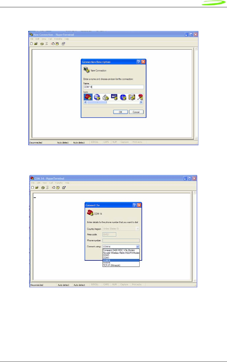
SETTING UP HYPERTERMINAL TO COMMUNICATE WITH THE MODEM
Ensure that the Mini-card is still powered on with a USB connection to the computer, and that it is
recognized by the computer as per the previous step.
Open up a HyperTerminal session by navigating to
Start\All Programs\Accessories\Communications\HyperTerminal.
17
Novatel Wireless
Revision 1
Type in a Connection Description title, such as the Active Primary COM Port number that was
identified earlier - click ‘OK’. See Figure 4 below as an example:
Figure 4 – HyperTerminal Connection Description Window
In the “Connect Using” pull down menu, select the proper COM port (Primary COM port number),
that the computer is using to communicate with the modem, then click ‘OK’. See the example in
Figure 5 below:
Figure 5 – HyperTerminal COM Port Selection Window
18
Novatel Wireless
Revision 1
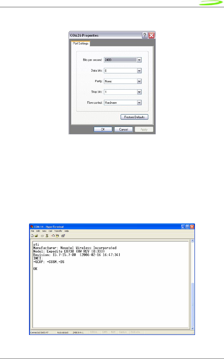
When the ‘COM XX Properties’ window comes up, just click on OK as there is no need to select
or modify any of these settings. Refer to Figure 6 below:
Figure 6 – HyperTerminal Properties Window
Now the modem should be automatically connected, as will be indicated in the bottom left corner
of the HyperTerminal window. To further ensure there is communication to the modem, type
“ATI” and press ENTER. The modem manufacturer, model number, FW revision and IMEI
information will then be returned as is shown in Figure 7 below.
If no information is returned in the HyperTerminal window after typing ATI, then click on the
Disconnect tab at the top of the HyperTerminal window (or click on Call\Disconnect). Reconnect
by clicking on the Connect tab at the top of the HyperTerminal window (or click on Call\Connect).
Now type ATE which will enable the “echo” function of the modem and therefore will allow the
characters typed in the HyperTerminal window to be displayed. Once this has been done, retype
the ATI command and all the modem information should now be displayed in the HyperTerminal
window.
Figure 7 – HyperTerminal Communication Window

19
Novatel Wireless
Revision 1

20
Novatel Wireless
Revision 1
Product Overview
The purpose of this section is to provide a high level overview of the EU860D & EU870D HSDPA
and E725 EVDO module.
HSDPA Module Overview
The EU860D is primarily targeted for the North American market while the EU870D is primarily
targeted for the European market. They are both wireless modem modules designed to be
embedded into laptop computers and other host devices.
The EU870D will operate in the 850/900/1800/1900 GPRS/EDGE bands and in the
850/1900/2100D UMTS/HSDPA band. The 2100 band supports receive diversity as indicated by
the “D” appended to the bands frequency. The EU870D is built on the MSM6280/RF Platform D
chipset from Qualcomm™ with Equalizer and receive Diversity supported. This product will be
commercially launched operating up to 3.6 Mbps and will be capable of future upgrade to
7.2Mbps.
The EU860D will operate in the 850/900/1800/1900 GPRS/EDGE bands, and 850D/1900D/21200
UMTS/HSDPA band. The 850D/1900D bands supports receive diversity as indicated by the “D”
appended to the bands frequency. The EU860D is built on the MSM6280/RF Platform D chipset
from QualcommTM with Equalizer and receive Diversity supported. This product will be
commercially launched operating up to 3.6 Mbps and will be capable of future upgrade to
7.2Mbps.
The modules will be compatible with Windows™ compliant applications including VPN, e-mail,
and web browsing.
The core protocol stack will be supplied by Qualcomm™ and contains UMTS, HSDPA, GPRS
and EDGE technologies. Around this core, Novatel Wireless has created the firmware drivers that
provide access to the hardware on the embedded modem. The feature set is comprised of the
data device features supported in the Qualcomm™ protocol stack.
The hardware consists of a PCI Express Mini Card compliant interface (except as detailed
herein), a baseband chipset from Qualcomm™, an RF radio chipset from Qualcomm™, and the
various other components used to support these major components.

21
Novatel Wireless
Revision 1
HSDPA Module Key Feature List
• Release 5 HSDPA Category 6
o Triband- UMTS/HSDPA 850/1900/2100
o Up to 3.6 Mbps DL
o Up to 384Kbps UL
• EDGE/GPRS class 12
• Quadband- GPRS/EDGE 850/900/1800/1900
• GPS
• SIM/USIM
• MobiLink and SDK available for third party dashboards
• Advanced HSDPA equalizer support
• HSDPA Category 8 (7.2 Mbps DL) Upgrade based on Qualcomm (Rel. 4.x Dec. 2006)
Network Overview
HSDPA (High Speed Downlink Packet Access)
HSDPA is based on WCDMA and is standardized as part of 3GPP Release 5 WCDMA
specifications. The new modulation method improves system capacity and increases user data
rates in the downlink direction. Key performance improvements are:
• Adaptive modulation and coding
• Fast packet scheduling function as controlled by the Node B (base station or BTS), rather
than by the radio network controller (RNC).
• Fast retransmissions (HARQ-Hybrid Automatic Repeat Request) with incremental
redundancy
The WCDMA system normally carries user data over dedicated transport channels, or DCHs.
HSDPA introduces a new transport channel type, High Speed Downlink Shared Channel (HS-
DSCH) that makes efficient use of radio frequency resources and accounts for bursty packet
data. The High Speed Downlink Shared Channel (HS-DSCH) shares multiple access codes,
transmission power and also shares infrastructure hardware between several users. The radio
network resources can efficiently serve a large number of users who are accessing bursty data.
Application Software Overview
MobiLink™ connection manager
Novatel Wireless provides Mobilink™ application software. The software is defined in later
Chapters.
MobiLink™ connection manager software to install and configure modem (for all supported
platforms)
Key Features
• AT Command Set Support per IS-707

22
Novatel Wireless
Revision 1
• Fully compatible and interoperable with current Microsoft™ OS platforms: PPC
2000/2002/HPC, Windows 98, Windows 2000, Windows ME, & Windows XP
• Integrated drivers for Windows OS, configurable as either a modem or network
card
• PCI Express Mini-card
• Compatibility with all major brands of PC's and PPC computing platforms
• Sleep Mode capabilities
• Uses common base technology shared with OEM Module
• IS-683A compliant - Over-The-Air activation and parameter update capabilities.
• On-line help, getting started guide, documentation
• All software applications necessary to communicate with the PCI Express Mini
Card will operate with the following platforms: PPC 200/2002/HPC, Windows 98,
Windows 2000, Windows ME, & Windows XP
• All software shall support 640x480, 640x240, and 800x600 color and
monochrome displays
• MobiLink allows the user to configure the modem easily
• MobiLink provides diagnostic capability
• MobiLink provides a Help menu that is Context Sensitive

23
Novatel Wireless
Revision 1
Device Specifications
PCI Express Mini Card
Novatel Wireless has designed a line of embedded broadband access modules around the PCI
Express Mini Card Specification 1.11 . This product line provides platform developers and system
integrators with the ability to enable global 3G broadband access. The governing body for PCI
Express standardization is PCI SIG (Peripheral Component Interconnect Special Interest Group.)
The website for PCI SIG can be found at the following URL:
www.pcisig.com/home
1 Customizations that deviate from the PCI Express Card Electromechancil Specification revision 1.1 are noted in this
document
24
Novatel Wireless
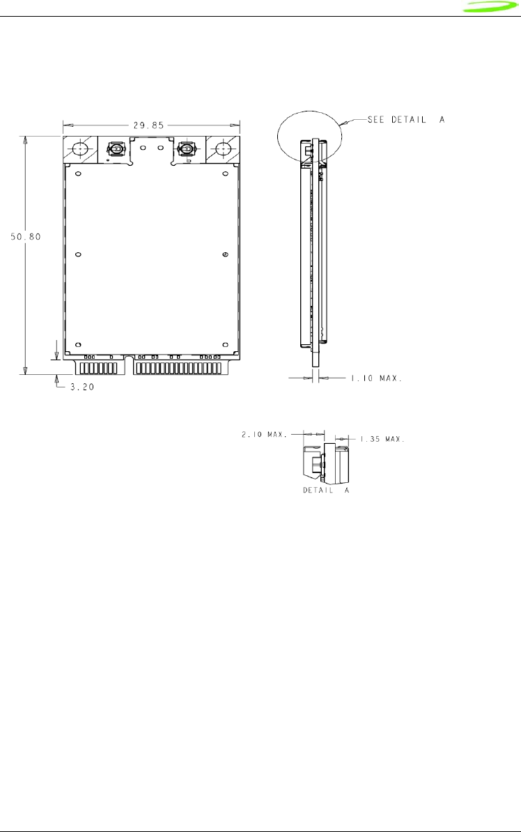
Revision 1
Figure 2: EU860D/EU870D Module
25
Novatel Wireless
Revision 1
Figure 3: EU860D/EU870D Module
26
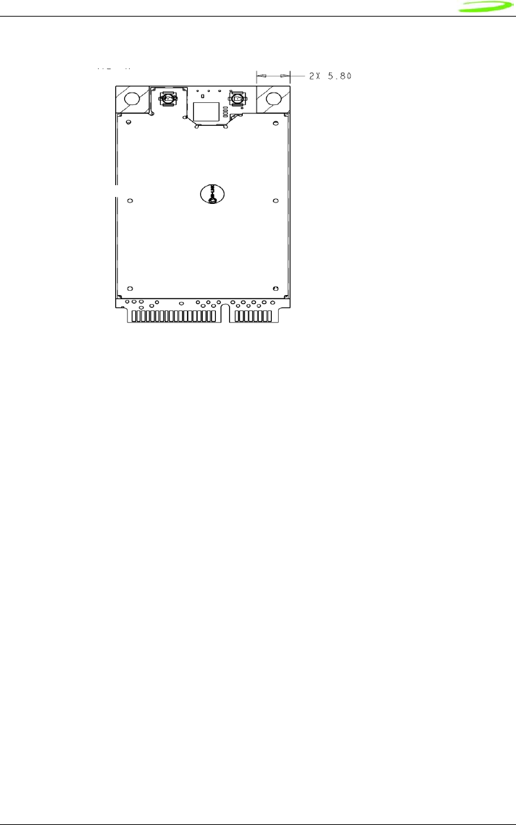
Novatel Wireless
Revision 1
Figure 4: PCIe Minicard Module Envelope
1.35 mm
5.0 mm

27
Novatel Wireless
Revision 1
Interface Specification
Host Interface
The E725 and EU860D/870D are designed to meet the PCI Express Mini-Card specification. The
table below gives a description of the pin-out and usage. The USB option of the specification is
supported. Deviations from the Mini PCI Express card specification 1.1 are noted.
Notes:
NC No Connect
W_DISABLE Radio Transmit Disable
NC/XXXX Standard product will have No Connect, Population option,
PCM_XXXX PCM Voice interface (Data in, Data out, Sync & clock)
28
Novatel Wireless
Revision 1
USB Interface
The Mini card acts as a peripheral device and supports the USB 2.0 standard at low speed (1.5
Mbps) and full speed (12 Mbps). It does not support the high speed (480 Mbps) mode of
operation.
Subscriber Identification Module (SIM) Interface (EU860D/EU870D only)
A 4 line SIM interface is provided on the mini-card edge connector for the EU860D/860. The
signal levels comply with the ETSI standard Specification of the 3 Volt Subscriber Identity Module
- Mobile Equipment (SIM-ME) interface (GSM 11.12 version 4.3.1). Note that no ESD protection
will be provided on the mini-card. The host device is expected to provide the ESD protection at
the SIM connector.
The OEM Module supports a 3.0V SIM as described in ETSI 11.12. The relevant signals are
brought out on the 70 pin connector.
• The SIM interface shall support 1.8 V USIMs
• The SIM interface shall support 3.0V USIMs
• The SIM interface shall support 3.0V SIMs
The USIM will be provided by the host. A SIM connector is not included on the mini-card. The
interface to the USIM is provided on the host interface connector. A recommended interface card
design criteria is available from Novatel. Please refer to the Integrator Design Elements:
Antenna, Power & SIM section for further details.

29
Novatel Wireless
Revision 1
Power Supply
The card shall operate within specification for the voltage range of 3.00 to 3.56 V with the nominal
voltage being 3.3 V.
The RF connectors shall be Hirose U.FL-R-SMT or equivalent. This connector is
designed for a limited number of insertions. For an embedded application this is
expected to be acceptable.
The connector location shall be as shown below:
The E725 and EU860/870 are designed to be connected to an external antenna integrated into
the host system. The antenna port presents a nominal 50Ω impedance.
Diversity
The EU860D shall support diversity on the UMTS/HSDPA 850 and 1900 bands. Roaming onto
the 2100 band is supported.
The EU870D shall support diversity on the UMTS/HSDPA 2100 bands. Roaming onto the 850
and 1900 bands is supported.
The EU870D/EU860D shall operate in the 850/900/1800/1900 GPRS/EDGE bands
Diversity is not supported in the GPRS/EDGE bands.
The E725 supports receive diversity in the 800/1900 bands.
Diversity/GPS Primary

30
Novatel Wireless
Revision 1
GPS
E725 EU860D/EU870D
GPS is supported. GPS is supported.
The EVDO Rev. A and HSDPA module receives GPS signals on the diversity antenna.
The EVDO Rev A and HSDPA module will support the following GPS features to the extent the
associated application and network also supports the operation of the features identified below.
Thus some of the features will not be operational until the application and/or network support is
available.
GPS Features
• GPS Standalone runs well without network
• GPS MS-Based gives fast fix and better sensitivity - requires periodic PDE support
• GPS MS-Assisted best coverage and best accuracy - requires constant PDE support
• GPS Control Plane network service completion
• GPS SMS Remote initiation with service payload for GPS tracking (planned)
GPS Application Services
• Simultaneous GPS fix and data session
• Autonomous GPS with caching of ephemeris and last fix
• Interfaces
– Serial NMEA interface pass-through
• MobiLink API for location request, tracking
– SMS Activated Location Responder
– GPS Timer and Fencepost trigger
• Application
– Common GPS client on host device
– Popular Adapters to Browser, Map, Traffic & POI client apps
– Vertical Market Subsystem enabler – client tracking & fixing
– Possible Location Server / Dispatch Assist

31
Novatel Wireless
Revision 1
Environmental
The EU860D/870D and E725 will be compliant with the Mini PCI Express Electromechanical
specification as detailed in the table below.
It should be noted that Novatel Wireless cannot guarantee that the host device (laptop; PDA;
notebook etc.) will be able to endure these same environmental conditions. Users are advised to
consult the host device documentation for specifications and observe any restrictions of use.
EU860D/870D & E725 Environmental Specification
Parameter E725 EU860D/860
Low Temperature Storage -30 °C -30 °C
High Temperature Storage 85 °C 85 °C
Low Temperature Operating -20 °C 0 °C Note 1
High Temperature Operating 65 °C2 65 °C
Relative Humidity
95% maximum (non
condensing)
95% maximum (non
condensing)
ESD EVDO Rev A 8kV Air / 4kV Contact
ESD HSDPA
USB & SIM Pins only
8kV Air / 4kV Contact
Performance Criterion 3
Vibration and High Frequency
147m/s2 (15G) peak; 10 to 2000
Hz
147m/s2 (15G) peak; 10 to
2000 Hz
Drop 75 cm 75 cm
Note 1: Low Temp Operation limit under review pending component review. Design target -20 °C
Note 2: Limit under review, design target for USB & SIM pins IEC 61000-4-2; Level 4 (ESD) 15kV air, 8kV contact.
The E725 product operates in a reliable fashion consistent with CDMA (IS-98C) and PCMCIA
V2.1 standards. It will withstand three-foot drop and still remain functional.
Electrostatic Discharge and Electro-Magnetic Interference
The modem does not protect itself from ESD. It is the responsibility of the host to ensure that
there will not be any harmful discharges to the modem.
With regard to EMI, the modem will meet FCC part 15 for North American markets, and ETSI EN
301 489-1 for European markets. This device when incorporated in any other product may require
FCC and/or other approvals. It is the user’s responsibility to do this.
2 It is required that the shield temperature not exceed 80°C at anytime. It may be necessary for
the system integrator to provide some method to insure this surface temperature is not exceeded.

32
Novatel Wireless
Revision 1
Integrator Design Elements: Antenna, SIM & SMBus
Antenna
HSDPA and EVDO Rev A Antenna Requirements
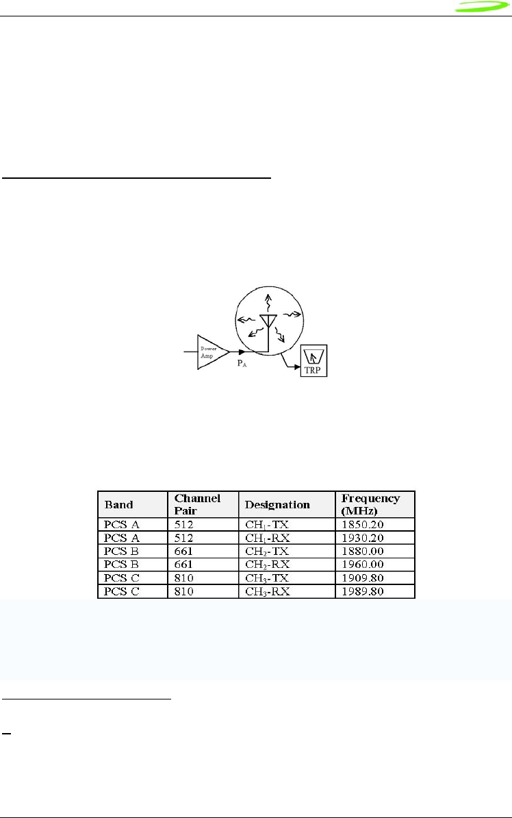
Total Radiated Power (TRP)
TRP measures the effective level of radiated power that is emitted while in transmit mode. To
quantify the performance of the transmitter, the output power is measured on a spherical surface
surrounding the laptop/handheld. The result of the measurement is a spherical radiation pattern
of the radiated power or EIRP (Effective Isotropic Radiated Power). To obtain a single figure of
merit the EIRP pattern is integrated over the spherical surface to obtain the TRP (Total Radiated
Power). Carriers provide antenna performance specifications which identify the necessary TRP
performance in order to be compliant with the carrier limits and attain Technical Acceptance.
Total Radiated Power Estimator
TRP can be estimated by summing the transmitted power of the Novatel Mini PCI Express cards
with the expected losses and antenna efficiency. A basic spreadsheet estimator3 is available
from Novatel Wireless and a sample is shown below. The EU860D/870D and E725 set points are
typical of factory production. The Cable & Connector Loss and the Antenna efficiency are
estimated by the host integrator to be representative of the laptop or handheld under
consideration. The results are typically compared against carrier requirements to estimate
compliance margin.
Total Isotropic Sensitivity (TIS)
TIS measures the effective sensitivity for a designated error rate. To quantify the performance of
the receiver, the receiver sensitivity is measured on a spherical surface surrounding the
Laptop/Handset. The sensitivity is defined as the minimum power level at which the digital error
rate of the receiver is better than a specific limit. Depending on the system this limit is a Bit Error
Rate (BER) limit, Block Error Rate (BLER) limit or a Frame Erasure Rate (FER) limit. Sensitivity is
measured by lowering the transmit power level of the base station simulator until the specified
digital error limit is reached. The power that was required to obtain the error limit is the sensitivity
value.
TIS (Total Isotropic Sensitivity) Estimator
TIS can be estimated by reducing the Conducted Sensitivity of the module by losses and
desense noise. The Conducted Sensitivity is reduced by Cable loss, Cable loss, Antenna
3 Disclaimer: This spread sheet is provided with no warranties whatsoever. Novatel Wireless disclaims all liability relating
to the use of information in this specification. Note that this table is provided for rough estimation purposes only and is
intended to provide a first pass guideline for antenna loss planning. It is not to be a substitute for detailed design activity.
Additional losses, efficiency considerations and other system affects will modify the actual resulting TRP and as such
results will deviate from the TRP calculator shown above. Updates to TRP limits are not controlled in this document.
33
Novatel Wireless
Revision 1
Efficiency and reduced by an estimation of the Laptop/Handheld noise. A basic spreadsheet
estimator4 is available from Novatel wireless and a sample is shown below.
The EU860D/870D and E725 conducted Sensitivity typical of factory production units will be
made available from Novatel Wireless. Although the data cards operate in Packet switched mode
the values used for estimation are from Circuit Switched mode of operation as this is the mode
the TIS is measured. The results are typically compared against carrier requirements to estimate
compliance margin.
TRP (Total Radiated Power) Requirements
Good radiated performance is critical to the effective operation of a mobile in networks. A
comprehensive characterizing of radiated performance enables carriers to know how well mobiles
work within the specific network design constraints.
Figure 5: Total Radiated Power
Tests shall be carried out for three different frequency pairs across the bands supported by the
device, as defined for CDMA TIA/EIA-98-D and for GSM 1900 3GPP TS 51.010 in the tables
below.
GSM-1900 Test Frequencies
Radiated power measurements will be recorded in the “free-space” configuration on all applicable
frequencies. For portable units, TPR measurements are repeated on all applicable frequencies.
4 Disclaimer: This spread sheet is provided with no warranties whatsoever. Novatel disclaims all liability relating to the
use of information in this specification. Note that this table is provided for rough estimation purposes only and is intended
to provide a first pass guideline for antenna loss planning. It is not to be a substitute for detailed design activity. Additional
losses, efficiency considerations and other system affects will modify the actual resulting TIS and as such results will
deviate from the TIS calculator shown above. Updates to TIS limits are not controlled in this document.

34
Novatel Wireless
Revision 1
TPR will be reported using the Figure of Merit for industry analysis. Device power shall comply
with the power levels specified in the relevant industry standards

35
Novatel Wireless
Revision 1
SIM Design Guidelines
Description
The SIM contains subscriber identification, specification and authentication information; and is
required to obtain service. 3.0V and 1.8V SIMs are supported. The physical size and contact
location for the “Plug-in SIM” format is defined in reference [2]. Contact identification is defined in
reference [7]. Electrical characteristics for a 3V SIM are defined in reference [3], and for a 1.8V
SIM in reference [4]. Power sequencing and general protocol operation is defined in reference
[8]. The figure below shows a “Plug-in SIM”.
C1
VCC C5
GND
C2
RST C6
VPP
C3
CLK C7
IO
C4
reserved C8
reserved
Figure 6: Plug-in SIM (shown from contact side)
References
1. 3GPP TS 01.04: "Abbreviations and acronyms"
2. 3GPP TS 11.11: “Specification of the Subscriber Identity Module - Mobile Equipment
(SIM - ME) interface”
3. 3GPP TS 11.12: "Specification of the 3 Volt Subscriber Identity Module - Mobile
Equipment (SIM - ME) interface".
4. 3GPP TS 11.18: “Specification of the 1.8 Volt Subscriber Identity Module - Mobile
Equipment (SIM - ME) interface”
5. 3GPP TS 51.010-1 “Mobile Station (MS) conformance specification; Part 1: Conformance
specification”
6. ISO/IEC 7816-1: “Identification cards – Integrated circuit cards with contacts – Part 1:
Physical characteristics”
7. ISO/IEC 7816-2: “Identification cards – Integrated circuit cards with contacts – Part 2:
Dimensions and locations of the contacts
8. ISO/IEC 7816-3 “Identification cards – Integrated circuit cards with contacts – Part 3:
Electronic signals and transmission protocols”
Operation of SIM interface
For the purposes of this document, the SIM interface is the interface between the SIM and the
laptop at the SIM connector. The ME includes the HSDPA module and laptop SIM circuit.
The SIM interface provides power, clock, reset and data to the SIM. The data is half-duplex (bi-
directional but only able to transfer data in one direction at any time) circuit implemented as an
open-collector signal. When data is transmitted, the ME or the SIM will pull the line to a low
voltage, otherwise the line is pulled up through a resistor. The SIM operates in a
command/response mode where it will only transmit data in response to a received command.
One exception to this is the Answer-To-Reset (ATR) when the SIM transmits data in response to
a reset.

36
Novatel Wireless
Revision 1
The SIM is interrogated during the boot sequence. First the SIM interface is power sequenced for
1.8 volt operation. If 1.8 volt operation is unsuccessful then the SIM interface is power
sequenced for 3.0 volt operation. Initially a large amount of data is transferred. After this the SIM
is periodically polled to insure it has not been removed.
The following is a high level summary of SIM operation:
1. power cycle at 1.8 volts
2. power cycle at 3.0 volts (if required)
3. SIM transmits ATR
4. ME and SIM exchange data continuously over several seconds
5. ME polls SIM every 25 to 30 seconds
Description of signals
The SIM interface consists of the signals listed in Table 1.
Table 1: SIM interface signals
Name MiniCard pin SIM pin
VCC 8 C1
RST 14 C2
CLK 12 C3
Reserved not connected C4
GND 4, 9, 15, 18, 21, 26, 27, 29, 34, 35, 40, 50 C5
VPP 16 C6
IO 10 C7
Reserved not connected C8
GND
The GND signal is the ground for the ME. All voltages are referenced to this.
VCC
VCC is supplied from the ME by a dedicated regulator. Operation is at 3V and 1.8V.
See Table 2 for a summary of the 3GPP electrical requirements.
Table 2: VCC electrical requirements
Symbol Conditions Minimum Maximum Unit
Vcc 3V operation 2.7 3.3 V
Vcc 1.8V operation 1.62 1.98 V
RST
RST is driven by the ME. A low signal indicates a reset condition.
See Table 3 for a summary of the 3GPP electrical requirements.
Table 3: RST electrical requirements
Symbol Conditions Minimum Maximum Unit
VOH I
OHmax = + 200 µA 0.8 x Vcc Vcc V
VOL I
OLmax = 200 µA 0 0.2 x Vcc V
tR tF 400 µs
37
Novatel Wireless
Revision 1
CLK
CLK is driven by the ME. It is the system clock for the SIM. It may be used by the SIM as a
processor clock. The frequency of this signal is from 1 to 4 MHz. The clock is not continuously
running and is stopped in between data transfers.
See Table 4 for a summary of the 3GPP electrical requirements.
Table 4: CLK electrical requirements
Symbol Conditions Minimum Maximum Unit
VOH I
OHmax = + 20 µA 0.7 x Vcc Vcc V
VOL I
OLmax = - 20 µA 0 0.2 x Vcc V
tR tF 50 ns
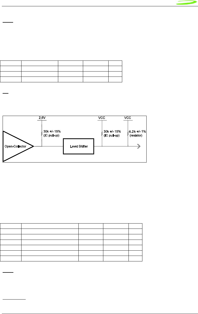
IO
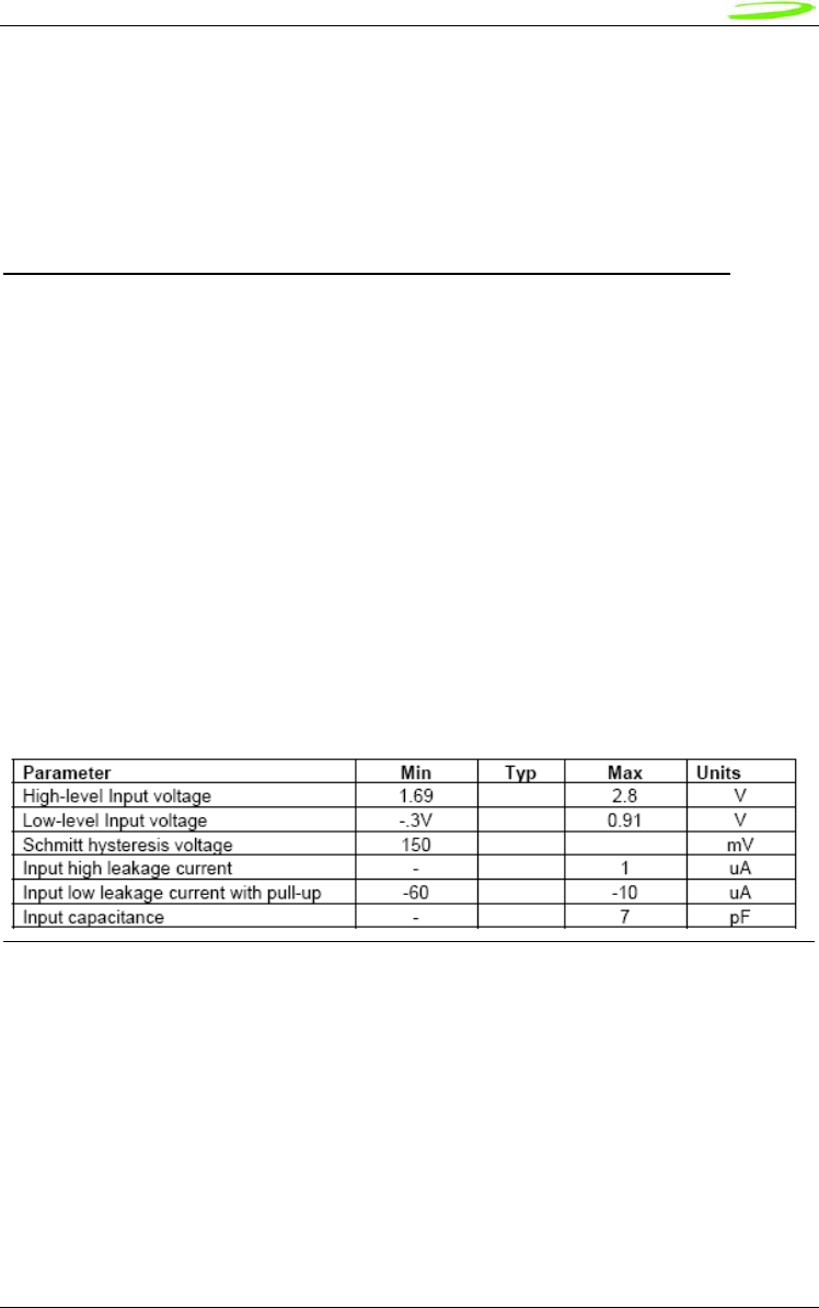
IO is the bi-directional data signal. The ME may drive this signal low, or may pull it up to VCC.
The SIM may drive this signal low, or it may pull it up to VCC. The pull-up on the HSDPA module
is described in the following figure.
Figure 7: IO driver and pull-ups
The IO signal is much slower than the CLK signal. The default bit time is 372 clock periods.
Each data word is 10 bit times; a start bit, eight (8) data bits, and a parity bit. The data signal
may be direct convention (high voltage is a binary 1, LSB sent first) or inverse convention (low
voltage is a binary 1, MSB sent first) depending on the ATR.
See Table 5 for a summary of the 3GPP electrical requirements.
Table 5: IO electrical requirements
Symbol Conditions Minimum Maximum Unit
VIH I
IHmax = ± 20 µA 0.7 x Vcc Vcc+0.3 V
VIL I
ILmax = + 1 mA - 0.3 0.2 x Vcc V
VOH I
OHmax = + 20 µA 0.7 x Vcc Vcc V
VOL Vcc = 3V, IOLmax = - 1mA 0 0.4 V
VOL Vcc = 1.8V, IOLmax = - 1mA 0 0.3 V
tR tF 1 µs
VPP
VPP is the programming voltage. It is not used and the SIM connector pin should not be
connected. The module pin is not connected.
Reserved
38
Novatel Wireless
Revision 1
The reserved pins should not be connected on the SIM connector. The SIM connector need not
have contacts at these locations.
Implementation
Refer to the figure below for the recommended circuit.
IO C1
CLK
RST
VCC
VPP
GND
HSDPA
Module
C2
C3
0.1 uF
SIM
Connector
C7
C3
C2
C1
C6
C5
pin 10
pin 12
pin 14
pin 8
pin 16
R1
D1
SRV05-4.TCT
6V
R3
R2
Figure 8: Reference circuit
C1, C2, C3
C1, C2 and C3 are not to be populated. They exist if additional filtering is required. These
components should be placed close to the SIM connector.
R1
R1 should be zero ohms. It exists if additional filtering is required.
R2
R2 should be zero ohms. It exists if additional filtering is required.
R3
R3 should be not be populated. It exists if pull-up adjustments are required.

39
Novatel Wireless
Revision 1
D1
D1 should be a low capacitance ESD diode array (5 pF or less). It is important to minimize the
capacitance on the IO line. D1 should be placed close to the SIM connector. There is no ESD
protection on the HSDPA module. It is recommended that the ESD protection meet IEC61000-4-
2, level 4 (±15kV air, ±8kV contact).
Signal routing
The CLK line is a high speed digital signal and care must be taken to insure it is isolated from the
other signals. A guard trace between it and the other signals should be used if they are to be
adjacent for any length. A multi-layer PCB with a ground plane should be used. Traces should be
as short as possible. All the SIM interface signals should be routed carefully to avoid being
corrupted by each other or external signals.
IO signal capacitance
The rise time of the IO signal is determined by the total capacitance on the line and the pull-up
resistance. The module has a maximum capacitance of 50 pF and the SIM is considered to have
a maximum capacitance of 30 pF. The laptop capacitance on the IO signal (including
connectors) should be as targeted to be lower than 30 pF. Additional capacitance may be
required to reduce noise, however the IO circuit rise time limit of 1 µs must be considered.
IO signal resistance
The SIM may also have a pull-up on the IO signal, which would have the effect of injecting up to 1
mA into the ME when the ME is transmitting a low level. Series resistance of the IO signal must
be kept very low as the voltage drop across it due to the injected current may cause the output
voltage to rise above the voltage output low specification.
Certification
As the SIM interface is unique to each laptop, each laptop must pass several test cases to obtain
certification. The SIM electrical test cases are specified in section 27.17.2 in reference [5].
The following is a summary of these tests:
• 27.17.2.1.1 Electrical tests on contact C1 (VCC) – Test 1
e.1) The voltage on contact C1 of the SIM/ME interface shall be 3V ± 10 % for Icc up to 6 mA
when the interface is in 3V operation mode.
e.2) The voltage on contact C1 of the SIM/ME interface shall be 1.8V ± 10 % for Icc up to 4
mA when the interface is in 1.8V operation mode.
• 27.17.2.1.2 Electrical tests on contact C1 (VCC) – Test 2
e.1) The voltage on contact C1 of the SIM/ME interface shall be 3V ± 10 % for spikes in the
current consumption with a maximum charge of 12 nAs with no more than 400 ns
duration and an amplitude of at most 60 mA when the interface is in 3V operation mode.
e.2) The voltage on contact C1 of the SIM/ME interface shall be 1.8V ± 10 % for spikes in the
current consumption with a maximum charge of 12 nAs with no more than 400 ns
duration and an amplitude of at most 60 mA when the interface is in 1.8V operation
mode.

40
Novatel Wireless
Revision 1
The following current spikes are applied (The specified spike durations are measured at 50 %
of the spike amplitude):
1) continuous spikes:
current amplitude 12 mA
current offset 0 mA
Duration 100 ns
Pause 100 ns
2) continuous spikes:
current 12 mA
current offset 0 mA
Duration 400 ns
Pause 400 ns
3) continuous spikes:
current amplitude 9 mA
current offset 3 mA
(i.e. maximum amplitude = 3 mA + 9 mA = 12 mA
Duration 150 ns
Pause 300 ns
4) random spikes:
current amplitude 60 mA
current offset 0 mA
Duration 200 ns
Pause between 0.1 ms and 500 ms, randomly varied
5) random spikes:
current amplitude 30 mA
current offset 0 mA
Duration 400 ns
Pause between 0.1 ms and 500 ms, randomly varied
6) random spikes
current amplitude 57 mA
current offset 3 mA
(i.e. maximum amplitude = 3 mA + 57 mA = 60 mA
Duration 200 ns
Pause between 0.1 ms and 500 ms, randomly varied
• 27.17.2.2 Electrical tests on contact C2 (RST)
e.1) The voltage on contact C2 (RST) of the SIM/ME interface shall be between 0.3V and
+0.7V for a current of 200 µA in low state and between 2.15 V and Vcc + 0.3V for a
current of +200 µA in high state when the interface is in 3V operation mode.
e.2) The voltage on contact C2 (RST) of the SIM/ME interface shall be between 0.3V and
+0.47V for a current of 200 µA in low state and between 1.3 V and Vcc + 0.3V for a
current of +200 µA in high state when the interface is in 1.8V operation mode.
• 27.17.2.3 Electrical tests on contact C3 (CLK)

41
Novatel Wireless
Revision 1
e.1) The voltage on contact C3 (CLK) of the SIM/ME interface shall be between 0.3V and
+0.47V for a current of 20 µA in low state and between 1.21V and Vcc +0.3V for a
current of +20 µA in high state when the interface is in 1.8V operation mode.
e.2) The rise and the fall time of the clock signal shall not exceed 50 ns when the interface is
in 1.8V operation mode.
e.3) The cycle ratio of the clock signal shall be between 40 % and 60 % of the period, in
steady state when the interface is in 1.8V operation mode.
e.4) The frequency of the clock signal shall be between 1 MHz and 4 MHz when the interface
is in 1.8V operation mode.
e.5) The voltage on contact C3 (CLK) of the SIM/ME interface shall be between 0.3V and
+0.6V for a current of 20 µA in low state and between 1.9V and Vcc +0.3V for a current
of +20 µA in high state when the interface is in 3V operation mode.
e.6) The rise and the fall time of the clock signal shall not exceed 50 ns when the interface is
in 3V operation mode.
e.7) The cycle ratio of the clock signal shall be between 40 % and 60 % of the period, in
steady state when the interface is in 3V operation mode.
e.8) The frequency of the clock signal shall be between 1 MHz and 4 MHz when the interface
is in 3V operation mode.
• 27.17.2.5 Electrical tests on contact C7 (IO)
e.1) ME receiving state A (low state):
With an imposed voltage of 0V the current flowing out of the ME shall not exceed 1 mA
when the ME is in 3V operation mode.
e.2) ME transmitting state A (low state):
The voltage shall be between 0.3V and 0.4V when a current of 1 mA flowing into the ME
is applied when the ME is in 3V operation mode.
e.3) ME transmitting or receiving state Z (high state):
The voltage shall be between 0.7*Vcc and Vcc + 0.3V when a current of 20 µA flowing
out of the ME is applied when the ME is in 3V operation mode.
e.4) The rise time and the fall time of the I/O signal shall not exceed 1 µs when the ME is in
3V operation mode.
e.5) ME receiving state A (low state):
With an imposed voltage of 0V the current flowing out of the ME shall not exceed 1 mA
when the ME is in 1.8V operation mode.
e.6) ME transmitting state A (low state):
The voltage shall be between 0.3V and 0.3V when a current of 1 mA flowing into the ME
is applied when the ME is in 1.8V operation mode.
e.7) ME transmitting or receiving state Z (high state):
The voltage shall be between 0.7*Vcc and Vcc + 0.3V when a current of 20 µA flowing
out of the ME is applied when the ME is in 1.8V operation mode.
e.8) The rise time and the fall time of the I/O signal shall not exceed 1 µs when the ME is in
1.8V operation mode.

42
Novatel Wireless
Revision 1
SM Bus Design Guidelines
Introduction
This section will describe the SMBus interface parameters ensuring interoperability with Novatel’s
PCI Express Mini Cards the SM Bus interface.
The SMBus is a two-wire interface through which various system components can communicate
with each other and the rest of the system. It is based on the principles of operation of I2C. See
the PCI Express Card Electromechanical Specification for more details on the functional
requirements for the SMBus.
The SMB_CLK signal and the SMB_DAT signal are available on pins 30 and 32 of the PCI
Express Mini connector.
This interface will support a subset of the specification as detailed in this section.
SMBus is an i2c based protocol that will drive a slave device and report various data regarding
mobile status or real-time e-mail to it, in accordance to the SMBus protocol specification. It is
important to note that the EU860D/EU870D & E725 PCI Express Mini-card acts as a bus
master and not as a slave.
I2C Controller
The controller is an I2C-compliant, master-only device. The controller can access all available I2C
slaves on the bus, but cannot be accessed by any other masters on the bus.
Both SDA and SCL are bi-directional lines, connected to a positive supply voltage via a current-
source or pull-up resistor. When the bus is free, both lines are HIGH. The output stages of
devices connected to the bus must have an open-drain or open-collector to perform the wired-
AND function.
A simplified version of the I2C bus operation is as follows:
• The master generates a START condition, signaling all ICs on the bus to listen for data.
• The master writes a 7-bit address, followed by a read/write bit to select the device as a
transmitter or receiver.
• The receiver sends an acknowledge bit over the bus. The transmitter must read this bit to
determine whether or not the addressed device is on the bus.
• Depending on the value of the read/write bit, any number of 8-bit messages can be
transmitted or received by the master. These messages are specific to the I2C device
used. After 8 message bits are written to the bus, the transmitter will receive an
acknowledge bit. This message and acknowledge transfer continues until the entire
message is transmitted.
• The message is terminated by the master with a STOP condition. This frees the bus for
the next master to begin communications.
• Data on the I2C-bus can be transferred at rates of up to 100 kbps in the Standard-mode,
• The number of interfaces connected to the bus is solely dependent on the bus
capacitance limit of 400 pF.

43
Novatel Wireless
Revision 1
HW Parameters
The System Management Bus (SMBus) is a two-wire interface through which various system
component chips can communicate with each other and with the rest of the system. It is based on
the principles of operation of I 2 C.
The reader is referred to SMBus reference as described in the System Management Bus
(SMBus) Specification, Version 2.0 for further details on its operation.
The peripheral board communicating to the SMBus must provide pull-ups to 2.6V. It is
recommended that a 2.7 K ohm pull connected to 2.6 Volt rail.
DC parameters
Symbol Parameter Limits Units
Min Max
VIL Data, Clock Input Low Voltage - 0.3 0.86 V
VIH Data, Clock Input High Voltage 1.78 2.77 V
VOL Data, Clock Output Low Voltage 0 0.45 V
ILEAK Input Leakage - - ±5 μA
VDD Nominal bus voltage 2.47 2.73 V
Table 2: SMBus DC specification
SM Bus interface Board
Pull up resistors on both lines (SMB_CLK and SMB_DATA) and solid ground connections are
necessary. Without proper pull up values and good ground and instability in communication will
be experienced.
As illustrated below it is recommended that a 2.7 K ohm pull connected to 2.6 Volt rail.
Figure 9: SM Pull-up Configuration
Host Board Novatel PCI Express Mini Card
Host Board Novatel PCI Express Mini Card
GPIO
2.6
V
2.7K
Peripheral
(Slave)
SMB_CLK Pin (32)
EU8X0/E725
SMB_DATA Pin (30)
GPIO
2.6
V
EU8X0/E725
2.7K
Peripheral
(Slave)

44
Novatel Wireless
Revision 1
MobiLink Connection Manager
Overview
The Novatel Wireless MobiLink™ Communications Software Suite is a family of wireless
connectivity applications that connect mobile devices using wireless wide area networks (WWAN)
as well as WiFi and Ethernet in a single application to allow quick and easy access to email, the
Internet and corporate networks anytime, anywhere. With MobiLink and a wide area wireless
device, mobile users can stay productive and connected to customers and colleagues while out of
the office. MobiLink is optimally engineered to work with all of Novatel Wireless' Wireless
Modems for best in class 3G wireless broadband access solutions.
The MobiLink Communications Software Suite of applications contains a messaging Client that
manages 2 way SMS operations, an address book Client that manages contacts and phone
number, connection manager that manages the connectivity, and a customization utility to
manage and generate install customization settings. The following section will detail the features
of each application.
Purpose
This section provides high level user interface information regarding the appearance and
operation of the MobiLink™ Connection Manager application developed for Windows 2000, XP
Pro, and XP Home.
Applicable Documents
All software names and version numbers displayed should meet the requirements outlined in the
Consistency & Naming Conventions Requirements Document. This document also covers
the requirements for the desktop, including the necessary icons and the use of the Start menu.
For more details on meeting the requirements for Microsoft™ Windows certification, refer to the
document entitled, Application Specification for Microsoft™ Windows 2000 and Windows
XP for Desktop Applications, which can be found on Microsoft™’s web site.
GENERAL FEATURES
User Interface Functionality
The first design principle for MobiLink applications is that the basic information and controls
needed for day-to-day operations are quickly and easily accessible while less frequently used
functions are located deeper in the menu system. The user interface is designed to be intuitive to
use and will not require a large learning curve for the average user. The second design principle
for MobiLink is to be easily customizable in order to be able to meet the various requirements of a
global market.
Layout
The general layout of the main windows is designed to display important information for
connectivity while making it easy to navigate to other functions. The main function such as mobile
status and signal strength display is shown in the main window. The connection button is
prominently displayed and easily accessible. The main MobiLink display is shown below.
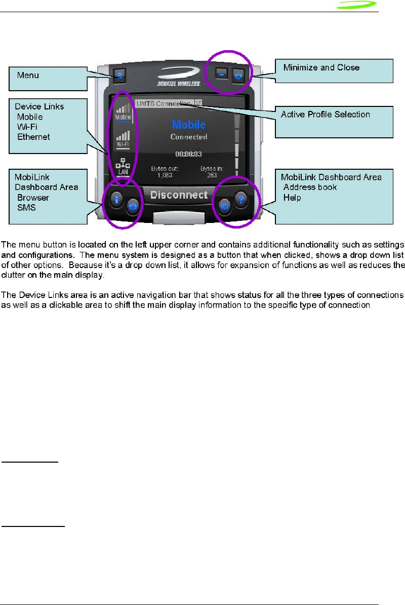
45
Novatel Wireless
Revision 1
Figure 10: Main MobiLink Display
The Dashboard Area in the layout is designed as a launching area for other applications. The
default applications in the current design are internet browser, SMS Client, Addressbook, and
Help file. Other applications can be launched.
The Active Profile Selection is a list that allows for easy access to choose the active profile to use
for connection. For 3G, this list is a list of connection profiles while for WiFi, this is a list of access
points found. For WiFi, this list also shows the signal quality and whether the access point is
encrypted.
Lastly, there are the standard minimize and close buttons that are the main stay of any
application. The minimize button hides the application as a tray icon and the close button
gracefully closes the application.
Mouse Over
Mouse over is a feature of the application that displays helpful hint about the function of the
application as the mouse is moved over an active area of the application such as the menu
button.
Snap to Edge
Snap to edge is a feature that makes the MobiLink application window snap to the sides of the
Windows desktop as the user drags the application close to the edge.
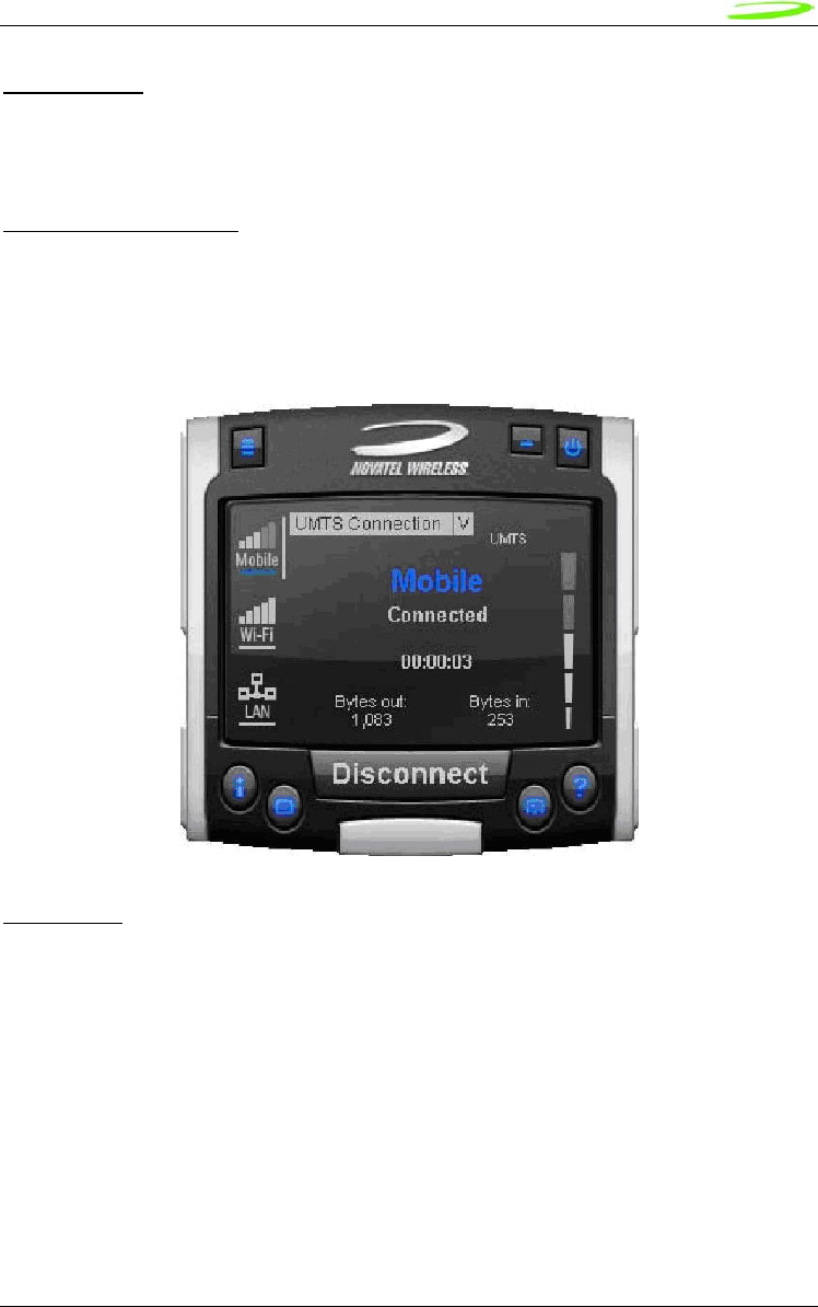
46
Novatel Wireless
Revision 1
Hot Swapping
The design of MobiLink allows for hot swapping of the 3G device. Users can plug and unplug a
3G wireless device and MobiLink will automatically recognize the technology and dynamically
change the display to show the relevant information.
Skinning Customization
Due to the software design and the underlying graphics engine used, the main “skin” of MobiLink
is completely customizable. The skin is contained in separate resource files that can be easily
changed for branding or function. One design is shown below and more can be developed.
Figure 11: Skin Design
Localization
It is the intent of the MobiLink™ connection manager design to be able to support localization.
Double byte Unicode is used and all the text used by MobiLink is kept in resource files that can
easily be translated and added. Currently MobiLink supports the following languages:
• Chinese Simplified
• Chinese Traditional
• Danish
• English
• French
• German
• Italian
• Spanish
• Swedish
• Polish
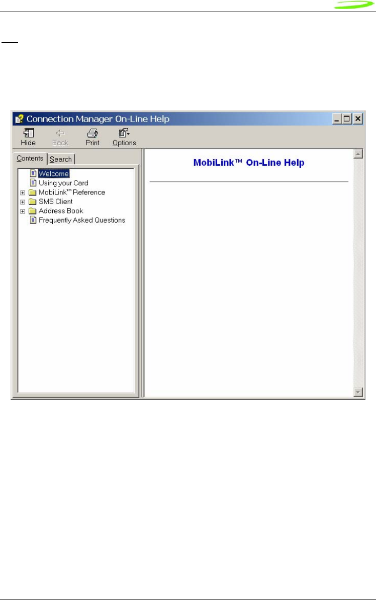
47
Novatel Wireless
Revision 1
File
The MobiLink™ connection manager shall contain a help file that can be accessed through a help
button or via F1 key. The help file is also localizable and is in HTML format as shown below:
Figure 12: On-Line Help
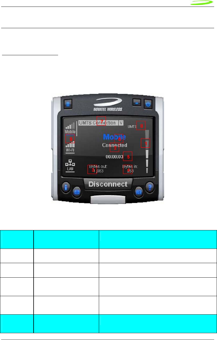
48
Novatel Wireless
Revision 1
MOBILINK™ FEATURES
The following sections describe the various features of MobiLink.
Main Display Window
The main display area of MobiLink is used for status indication of the different types of
connections. The following information is displayed.
Figure 13: Status Indication
Status Indication
Number
Reference
Status Information Description
1 Signal Strength Bar This is the quality of the signal for the selected
2 Connection Status This is a text indicating the connection status
3 Connect Duration This indicates the number of hours, minutes, and
seconds the current connection has been up
4 Bytes Out/Packets Out This indicates the number of bytes sent for the
current connection
Number
Reference
Status Information Description

49
Novatel Wireless
Revision 1
5 Bytes In/Packet In This indicates the number of bytes received for the
current connection
6 Network Name For UMTS/HSDPA, this would show the network
name received from the AT+COPS command
7 Profile List This is the list of supported profiles that contains the
connection settings such as username and
password and QoS for 3G. This is a list of the 3G
profiles for the 3G networks and a list of WiFi
profiles for the WiFi network. The displayed profile is
the active profile.
8 Indicators The indicators are icons that show additional status
of the 3G wireless. Each indicator will be described
below.
9 Connection Type Selection
Bar
This is a navigation bar that selects which
connection information is displayed in the main
window. As the connection is selected, the main
window will slide to show the right information. Each
of the connection icons for this navigation bar also
shows the signal strength of the respective
connection.
The connection navigation bar was added to support the universal connection management
functionality. By having a navigation bar, the user is presented with just the information that is
required for the connection of interest. The pictures below show the three views for each
connection type.
Figure 14: 3G Wireless View
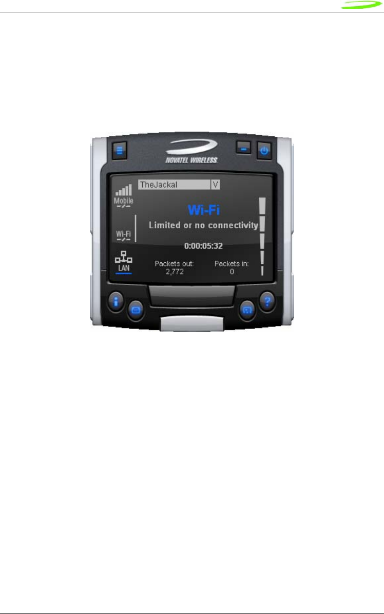
50
Novatel Wireless
Revision 1
With the 3G Wireless view, connection button can be used to connect to the chosen profile
displayed. The status icons for 3G will be displayed on the top right corner and when connected,
byte count and time displayed will be shown. The vertical bar next to the navigation bar indicates
which view is currently active. When the user clicks on the WiFi navigation button, the WiFi view
will be shown.
Figure 15: WiFi View
The WiFi view does not have a connection button since WiFi is a connectionless adaptor. The
view does show signal strength, packet count, and connection time as well as connection status.
Since MobiLink’s WiFi is developed using Windows zero configuration, MobiLink WiFi control can
coexist with Windows wireless network connection. The default hotspot is shown in the selection
list in the same place as the 3G profile list. The list of hotspots is dynamically generated based on
a WiFi network scan of the area. Users can chose to make another hotspot active by clicking on
the selection list shown below.
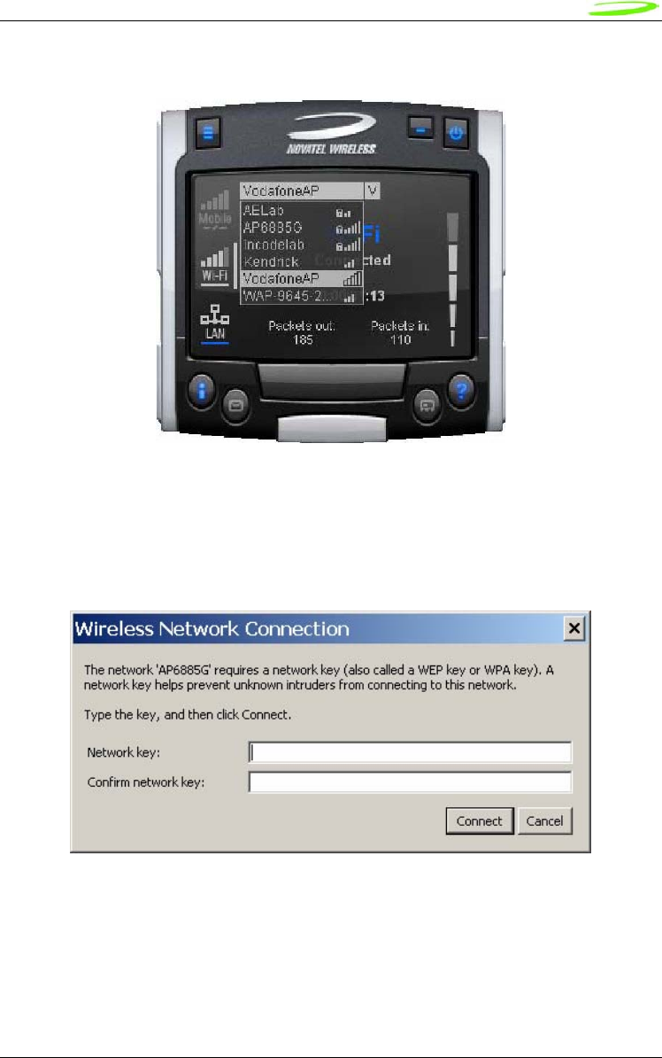
51
Novatel Wireless
Revision 1
Figure 16: HotSpot Activation
The connection list displays all the available hotspots seen by the WiFi adaptor. The list is
arranged in alphabetical order and the signal level for each is shown on the side. Also, if the
hotspot is WEP protected, a lock icon will be shown. To change hotspot, users can select one
from the list. If the hotspot is WEP protected the following dialog will be displayed to query for the
network key.
Figure 17: Network Connection
Lastly, the user can view the Ethernet connection by clicking on the Ethernet navigation bar icon.
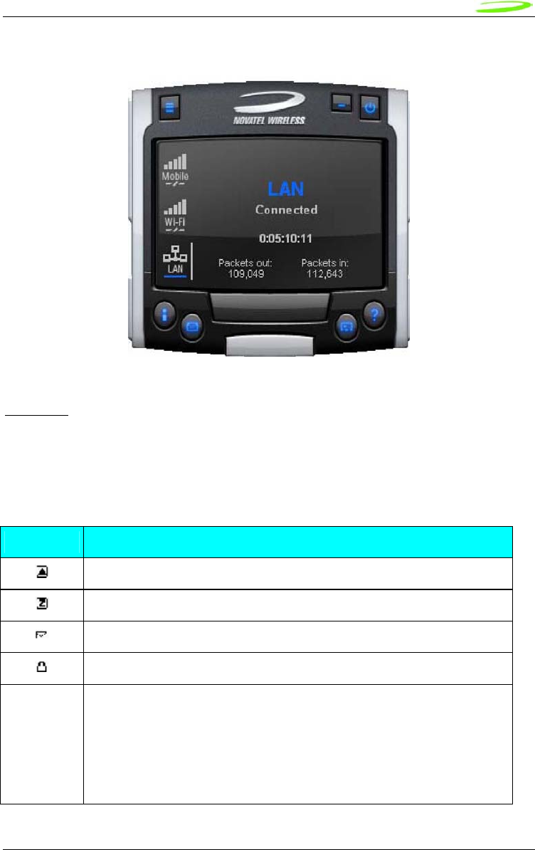
52
Novatel Wireless
Revision 1
Figure 18: Ethernet View
The Ethernet view shows the connection status, the packet count, and the connection duration.
Indicators
3G indicators are shown on the right upper corner of the main status display. The design of these
indicators is based on standard 3G indicators used on mobile devices. The following table
describes all the indicators.
3G Indicators
Indicator Status/Description
3G radio is roaming
3G in dormant mode (May not be applicable for all MAs)
New SMS is available
3G device is locked
WWAN
Network
This is the type of WWAN protocol that is acquired. The types are:
• HSDPA • UMTS
• GPRS • GSM
• IS95a • 1XRTT
• EVDO
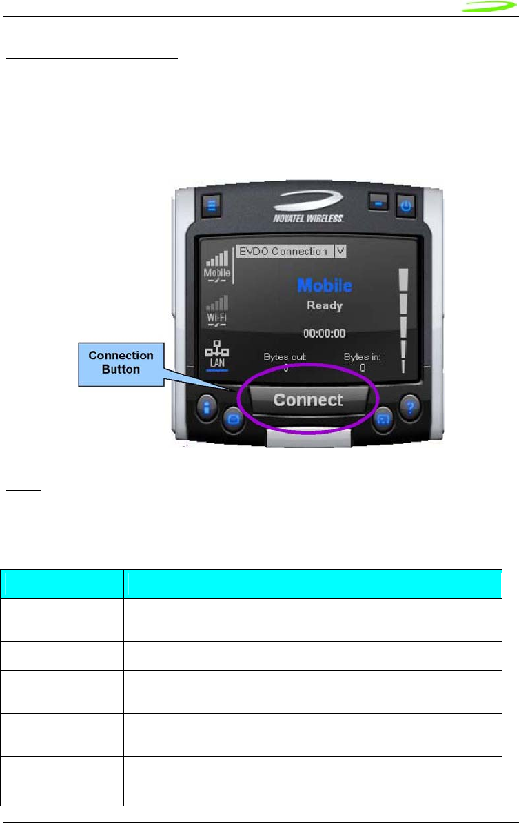
53
Novatel Wireless
Revision 1
Connect/Disconnect Button
Since the main purpose of MobiLink’s connection manager is for connecting the user to the
internet, the connection button is prominently placed. The Connection button is used to initiate a
3G data connection. The connection button is not used for WiFi or Ethernet since the network
adaptors are connectionless and will automatically connect as long as there is a valid connection.
Figure 19: Connection Button
Menu
When the Menu button is clicked, the following menu subjects are displayed:
Menu Subjects
Menu Item Description
Profile Manager This menu item opens up the dialog for creating, editing, and deleting
profiles
Configuration This menu item opens up a dialog for changing MobiLink settings
Properties This menu item opens up a dialog that displays the properties of the
3G modem
Report This menu item opens up a dialog that displays the connections
statistics and connection history
Transparency This menu item is to set the application display transparency. This
feature allows the desktop items below the application to be shown
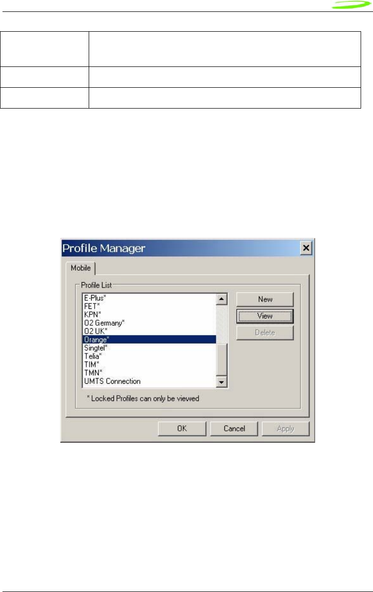
54
Novatel Wireless
Revision 1
through the transparency
About This menu item brings up information about the MobiLink application
Exit This menu item will quit the MobiLink application
Profile Manager
The profile manager allows the user to manage the connection profiles for both the 3G
connection and WiFi connection. The user can create a profile using the New, edit or view the
profile, and delete a profile.
3G Wireless Profiles
The first tab shows the 3G wireless profiles as shown below.
Figure 20: 3G Profiles
The wireless profiles can be selected for viewing in the case of a locked profile and for editing in
the case of an unlocked profile. Locked profiles are preset and can not be deleted or altered.
This is to reduce the incidence of connection problems related to incorrect settings due to user
error. The dialog below shows the actual profile settings. For locked profiles, the settings are
grayed out and cannot be modified.
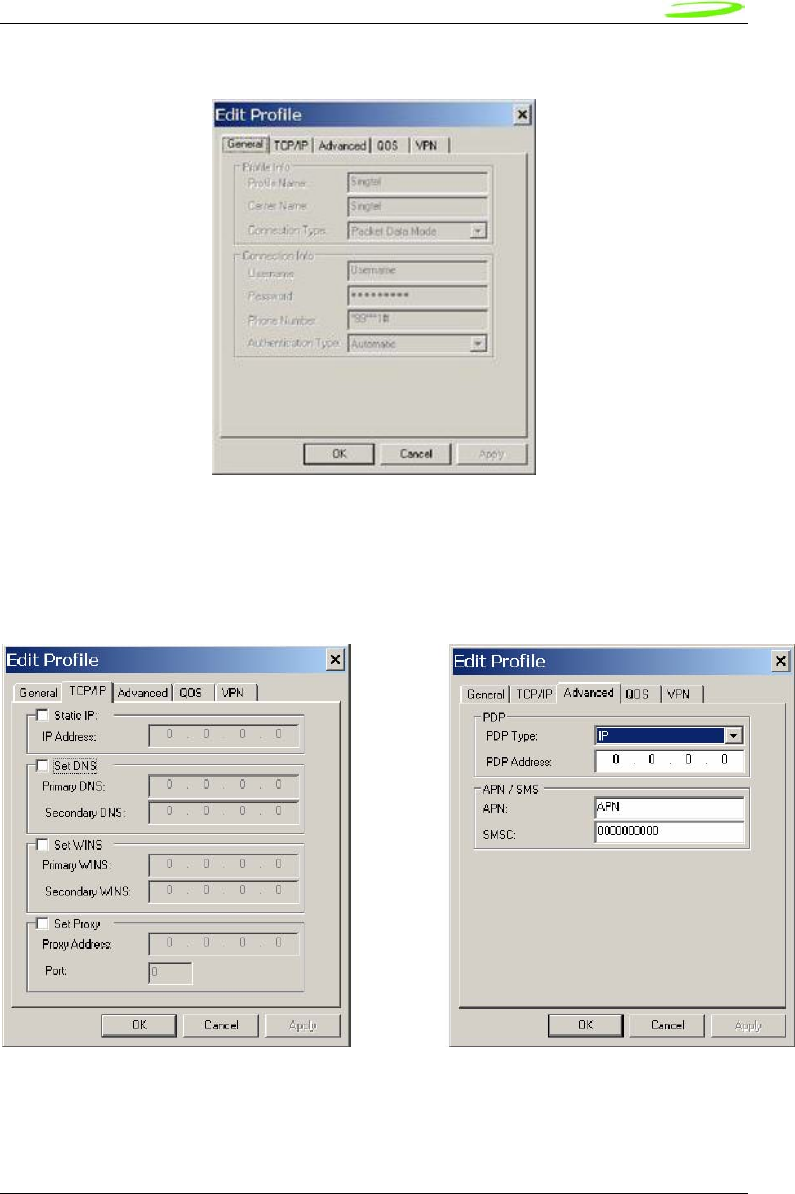
55
Novatel Wireless
Revision 1
Figure 21: Profile Settings
The profile settings are categorized under different tabs and can be different for UMTS and
CDMA. In the case of CDMA, the QoS tab does not apply. The following screens show the
various settings under each tab.
Figure 22: Different Tab Settngs
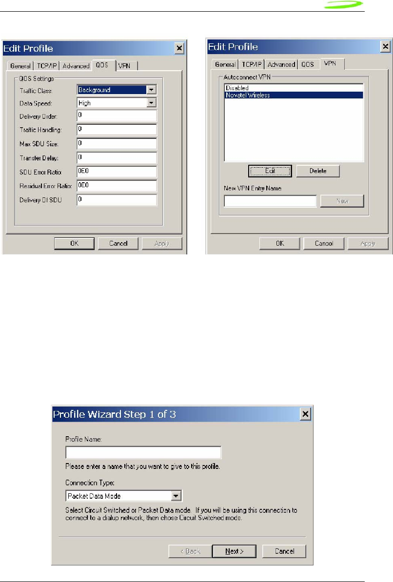
56
Novatel Wireless
Revision 1
When changes are made to any of the tabs, the user must click the Apply button to effect the
changes. Cancel can be clicked to cancel the settings. The exception is the on the last VPN tab.
When creating a new VPN, the VPN entry is created when the user clicks the New button with an
entry name. The apply button is used to change the associated VPN for the profile. VPN
association is used to automatically establish a VPN session after a successful 3G connection.
When creating a profile by clicking on the New button, the profile wizard is used to guide the user
through some simple steps for creating a new profile. The advanced settings are preset based on
a template profile for the carrier network and hidden from the user. In the rare case where
advanced parameters need to be changed, the user can then select the newly created profile and
click on Edit to edit the parameters.
Figure 23: Profile Wizard Step 1
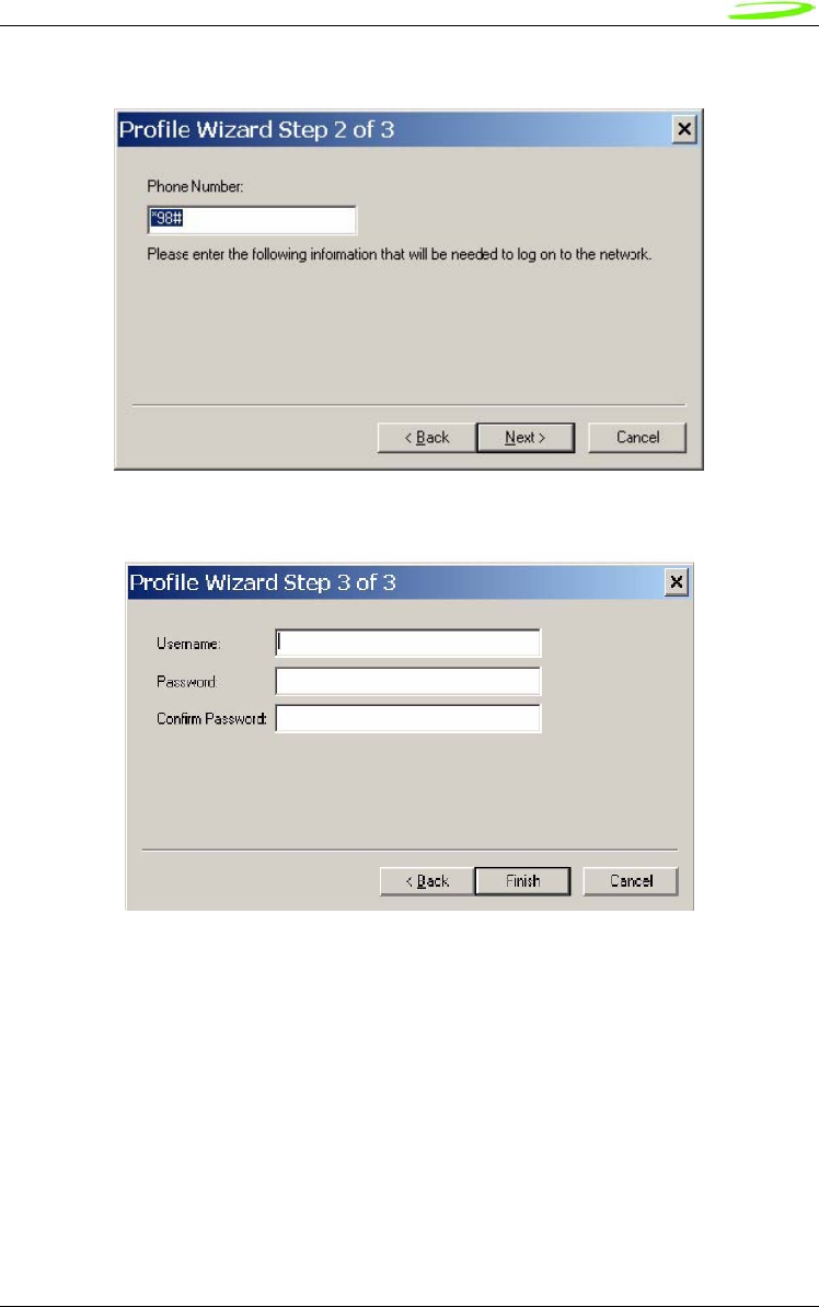
57
Novatel Wireless
Revision 1
Figure 24: Profile Wizard Step #2
Figure 25: Profile Wizard Step #3
WiFi Profiles
TBD
Configuration
The configuration menu has all the available settings for MobiLink. The configuration window is
broken down in to four functional tabs. The General tab is for the user interface settings and
language selection. The Mobile tab is used to set parameters for the 3G device. The WiFi tab
has settings for WiFi adaptor, and the Ethernet tab is used to set the Ethernet adaptor. Each of
the tabs is shown below.
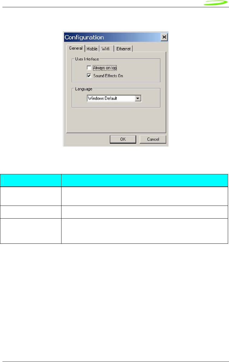
58
Novatel Wireless
Revision 1
Figure 26: General Tab
General Tab Features
General Tab Feature Description
Always on top When checked, the application is always the top most application on
the desktop
Sound Effects On When checked, sounds will be played on user actions
Language This is a selection list for choosing the language to be used for
MobiLink. Windows Default will base the language on what Windows
uses as the native language
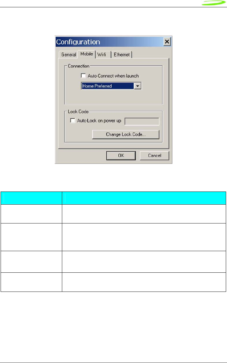
59
Novatel Wireless
Revision 1
Figure 27: Mobile Tab
Mobile Tab Features
Feature Description
Auto-Connect when
launch
This feature is for MobiLink to automatically connect to the network
when launched
Network Selection This selection is used to select the network preference. For CDMA,
this is to select the operating network and for UMTS/HSDPA, it’s for
selecting the radio access technology
Auto-Lock on power up Check to lock the SIM upon power up. A 4 to 8 digits code must be
supplied to turn on and off the auto lock feature.
Change Lock Code Chick this button to change the lock code. This button is only active
if the auto-lock SIM feature is turned on.
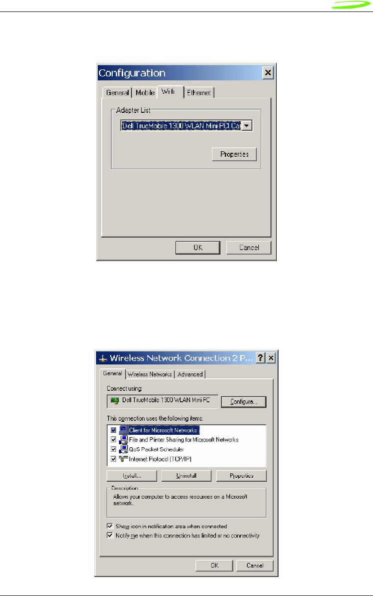
60
Novatel Wireless
Revision 1
Figure 28: WiFi Tab
The WiFi tab allows user to choose the WiFi adaptor from a list of detected adaptors. Also, the
adaptor properties can be modified by clicking on the properties button. The wireless adaptor
properties window is shown below.
Figure 29: WAP Window
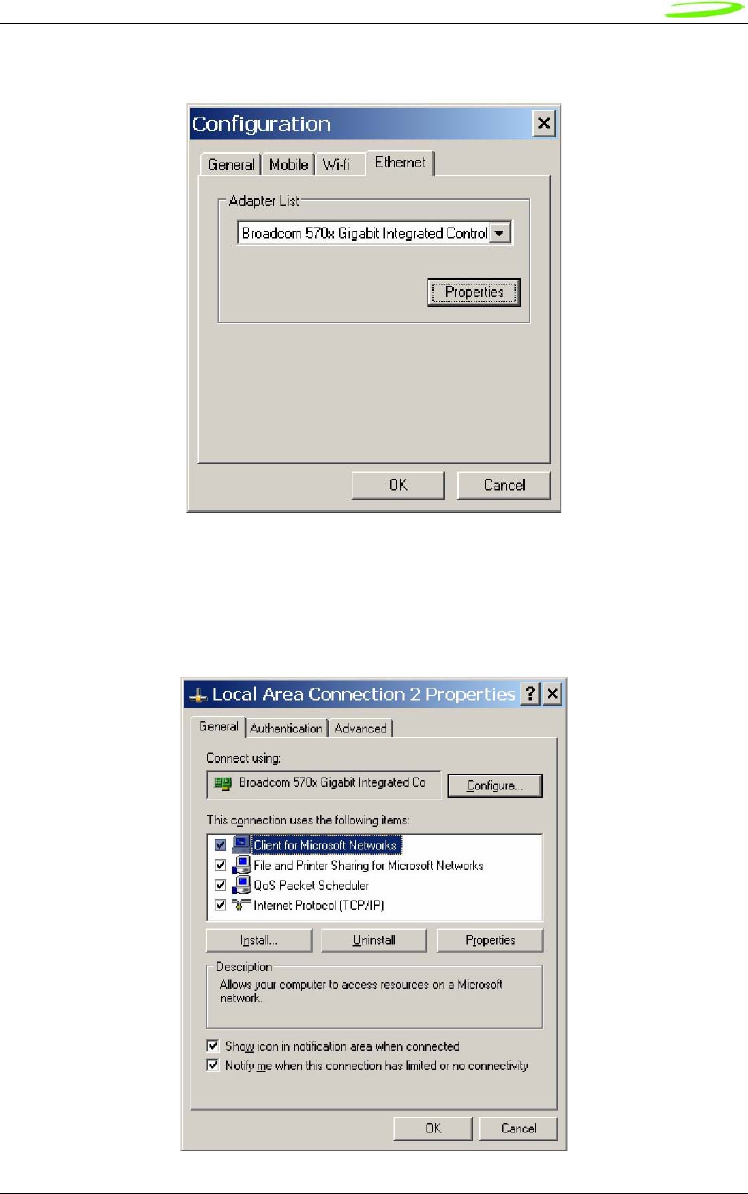
61
Novatel Wireless
Revision 1
Figure 30: Ethernet Tab
The Ethernet tab allows user to choose the Ethernet adaptor from a list of detected adaptors.
Also, the adaptor properties can be modified by clicking on the properties button. The adaptor
properties window is shown below.
Figure 31: AP Window
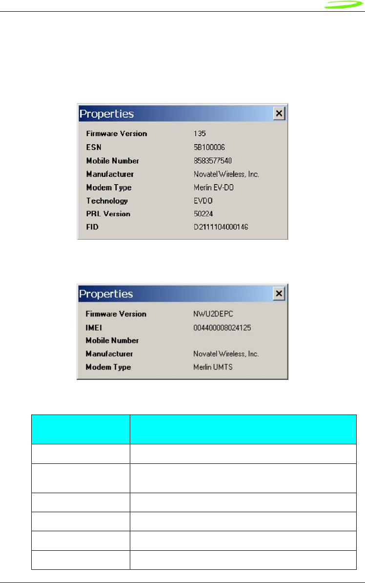
62
Novatel Wireless
Revision 1
Properties Menu
The properties menu displays some of the key properties of the UMTS and EVDO devices.
Figure 32: CDMA
Figure 33: UMTS/HSDPA
Identity Properties
Property Description
Firmware Version Firmware version of the 3G device
IMEI/ESN International Mobile Equipment Identity (UMTS)/ Electronic
Serial Number (CDMA)
Mobil Number Number for the mobile
Manufacturer Who produced the modem
Modem Type Modem technology
Technology 3G technology
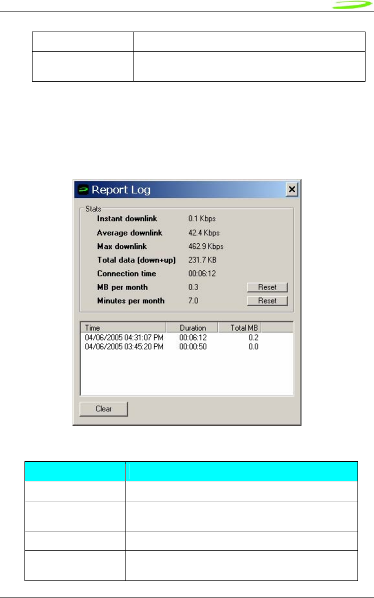
63
Novatel Wireless
Revision 1
PRL version Preferred Roaming List version number(CDMA)
FID Factory ID. This is a unique tracking number for factory
builds
Report Log
The report log has statistic information about the current connection as well as a history list of
past connections.
Figure 34: Report Log
Report Values
Value Description
Instant downlink This is most recent measured downlink throughput
Average downlink This is the average of all the measured downlink
throughput
Max downlink This is the maximum achieved downlink throughput
Total data This is the total data that has been ever sent since
MobiLink has been installed on the machine
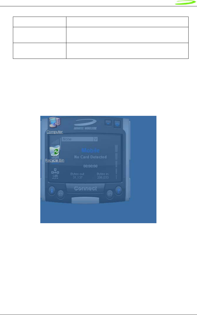
64
Novatel Wireless
Revision 1
Connection time The is the amount of time the connection has lasted
MB per month This is a resettable counter of how many bytes since the
last reset
Minutes per month This is a resettable counter of how many minutes since the
last reset
Transparency
This menu feature allows the user to select the percent transparency for MobiLink. The choices
range from 0% to 90% with 0% being solid and 90% being very transparent. Transparency
allows desktop items below MobiLink to be displayed for better multitasking. Below is an
example of MobiLink transparency on a desktop.
Figure 35: Desktop Transparency
About
The About dialog displays MobiLink information such as version number, release date, and
copyright.
65
Novatel Wireless
Revision 1
Figure 36: About Dialogue
SIM/Lock Management
Upon MobiLink startup, if the device is locked on power up, a small dialog will be displayed such
as below to ask the user to enter the unlock code prior to continuing with MobiLink.
Figure 37: Enter PUK
The lock setting and code can be managed in the Mobile tab of the configuration menu shown
below.
Figure 38: Configuration Menu
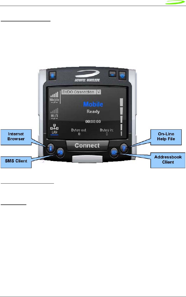
66
Novatel Wireless
Revision 1
Quick Access Buttons
The quick access buttons are designed to provide a launch pad for other applications. Four
buttons are provided and can be remapped to other applications. The picture below shows the
default functions assigned to the quick access buttons.
Figure 39: Quick Access Button Default Functions
Software Web Upgrade
TBD
SMS Client
The MobiLink SMS Client is used to manage reading and sending SMS messages. The SMS
Client is an application that is part of the MobiLink application suite. The design of this
application is to emulate an email Client to reduce the amount of new learning that is required to
start using this application. This application is launched from the main connection manager Quick
Access button. The following features are supported.
• Send new messages
• Reply to message
• Forward message
• Email interworking
• Concatenated SMS
• Set priority of message
• Rich text editing functions
• Printing
• Support for embedded hyper links and email links in message
• Auto language selection
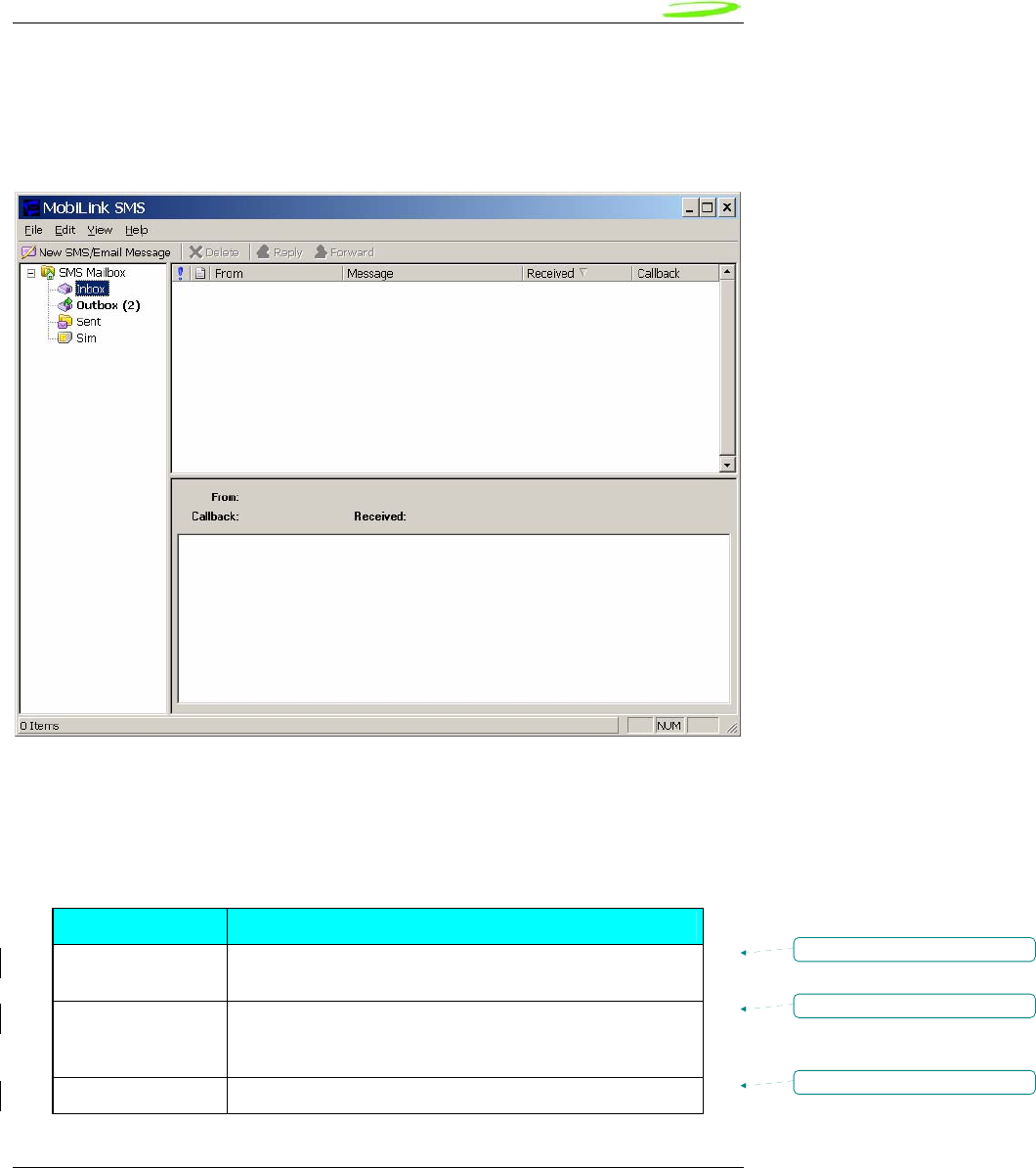
67
Novatel Wireless
Revision 1
• Send to multiple recipients
• Status receipt of sent messages
• Status bar to indicate number of messages, character count, etc…
Figure 40: MobiLink SMS Client
SMS Mailboxes
Very much like an email Client, the SMS Client has multiple mail boxes to store different types of
messages.
Mailbox List
Mailbox Description
Inbox All incoming SMS is delivered to this mail box and will be
highlighted if unread.
Outbox All outgoing SMS will be put into this mailbox. If the SMS has
not been sent to the card, it will be held here until it can be
sent.
Sent All sent SMS messages are placed here.
Formatted: Centered
Formatted: Centered
Formatted: Centered

68
Novatel Wireless
Revision 1
SIM All SMS messages that are still stored on the SIM.
The message panel contains the key information for a list of messages. The messages can be
reorded in the message panel by clicking on the fields located on the top strip. The fields are the
following:
Fields List
Field Description
! Importance
From Where the message is from. Only shown when
Inbox is selected.
To Where the message is sent. Only shown when
Outbox or Sent box is selected.
Message Displays the first few characters of the
message
Received Time when the message is received
Sent Time when the message is sent
Callback Callback number
Menu Bar
The menu bar contains the following items:
Menu Item Description
• File o Exit Exits the application
• Edit o Undo Undo last text editing
o Cut Cut the selected text
o Copy Copy the selected text
o Paste Paste text on clipboard
o Select All Select all text in message content panel
• View o Toolbar Display tool bar
o Statusbar Display Status bar
• Help o About SMSClient Display About dialog
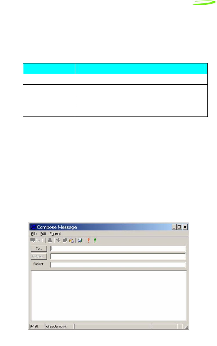
69
Novatel Wireless
Revision 1
Toolbar
The tool bar is accessible across the top and gives user quick access to common tasks. The tool
bar contains the following buttons:
Tool Bar Button
Button Description
New SMS Message Opens up dialog to create a new SMS message
Delete Deletes the highlighted message or group of messages.
Reply Reply to the highlighted message.
Forward Forward the contents of the highlighted message.
Status Bar
The status bar displays information about each of the mailboxes selected. It will give the number
of messages and the number of unread messages. The status bar is located on the bottom strip.
Compose Message Window
Clicking on the New SMS Message button will bring up the following dialog: This window allows
the user to enter the destination address, SMS message, a callback number for CDMA, and a
subject text. Standard text editing such as cutting, copying, pasting is supported in the message
box. In addition, the user can use the tool bar or the menu to set the priority and encoding of the
message. Both Unicode and ASCII are supported. Unicode is used to send characters not in the
standard ASCII character set.
Figure 41: Compose Message
70
Novatel Wireless
Revision 1
For the destination address, users can chose to select from the address book by clicking on the
To button. Also, multiple destinations can be entered separated by a comma or semicolon.
The toolbar supports the following functions: Clicking on the “To” button or the Addressbook
button will bring up the following dialog to select the contact to insert into the destination field.
Multiple destination addresses can be selected.
Destination Addresses
Button Description
Send Send the SMS message
Print the SMS message
Editing functions. Cut, copy, and paste text
Open the addressbook to select from
! Emergency priority
! Urgent priority
Set Unicode encoding for message
Email Interworking
A new feature added to this version of MobiLink is the ability for email interworking. What this
feature does is to allow an email message to be sent over an SMS message. If the user types in
an email address in the To field, the application will automatically format the SMS message so
that the SMSC on the network side will forward it as an email.
The recipient of this email can simply reply to the message and the message will be forwarded
back to the wireless device.
Concatenated SMS
With the addition of email interworking, the ability to send an SMS that is longer than the limited
160 characters is very important. To address that issue, the SMS Client will allow the user to
enter a long message and automatically segment the message and send it as separate SMS with
a special tag to indicate the messages are segments of a long message.
Addressbook Features
The MobiLink address book allows the management of phone numbers on the SIM, Windows
Address Book and Outlook. The following screen shows the address book Client.
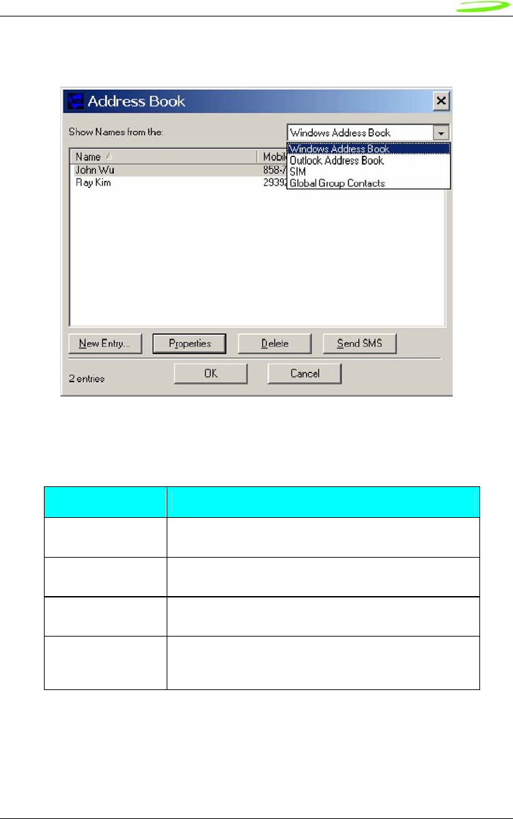
71
Novatel Wireless
Revision 1
Figure 42: Address Book
The address book Client has a selection box that allows the user to chose which address book to
view. The following addresses can be selected:
Address Books
Address book Description
Windows Address
Book
This is the native Windows Addressbook that is part of
Windows Accessories folder
Outlook Address
Book
This is the local Outlook Addressbook. This is only
accessible if Outlook is installed on the computer
SIM This is the address book located on the 3G device or the
SIM of the device
Global Group
Contact
This is the group contacts that contain distribution lists
created by the user. This list can contain contacts from
any of the above address books
User can create, delete, and view contact properties as well as send an SMS message using the
selected contact by clicking on one of the buttons on the bottom of the Address Book Client.
Global Group Contact
Global Group Contact feature allows users to create distribution lists for sending SMS.
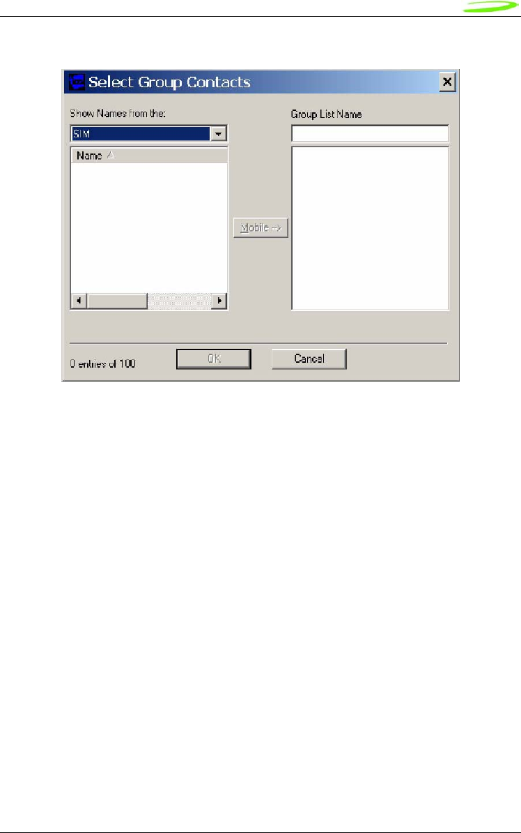
72
Novatel Wireless
Revision 1
Figure 43: Select Group Contacts
When the user chooses to create a Global Group Contact, a new dialog will be opened up to
allow the user to select from the different address books and move them to create a new
distribution list. The total number in a distribution list is up to 100. The list can contain a mixture
from different address books and can contain both mobile numbers as well as email addresses.

73
Novatel Wireless
Revision 1
Appendix C - Regulatory Approval and Compliance
As both the EU860D and EU870D support four bands of GPRS operation, including North
American and European bands, both products are covered by regulatory requirements of North
America and Europe. Both products will have FCC, PTCRB, CE and GCF certification.
The E725, as a CDMA product in North America requires FCC certification.
FCC (Federal Communication Commission)
The E725, EU870D and EU860D products conform to the requirements of applicable American
laws with respect to safety; health, environment and consumer protection.
This E725, EU870D and EU860D will comply, per applicable band, with the following parts of the
Federal Communication Commission’s (FCC) Code of Federal Regulations (CFR):
FCC CFR47 Part 2 (General Rules and Regulations, RF Exposure Evaluation)
FCC CFR47 Part 15 (All Radio Frequency Devices)
FCC CFR47 Part 24 (Narrow and wideband PCS modules)
FCC CFR47 Part 22 (Cellular Service)
A FCC grant shall be obtained in order to demonstrate compliance.

74
Novatel Wireless
Revision 1
CE (Conformance European)
The EU870D and EU860D products comply with the essential requirements of the applicable
European laws and directives with respect to safety; health, environment and consumer
protection. The products conform to the essential requirements of the R&TTE (Radio and
Telecommunications Terminal Equipment) Directive, 1999/5/EC, and have the CE mark affixed.
The applicable sections of the following standards have been used to demonstrate compliance to
this requirement. The EU860D and EU870D products will comply with the 3GPP standards TS
51.010 for GSM and TS 34.121 for WCDMA.
R&TTE
R&TTE
Requirement Discipline Definition Applied Standard
Article 3.1(a) Health Safety Testing
(flammability, etc…)
ICNIRP 19985 European Council
Rec.1999/519 EC
Article 3.1(a) Safety IEC 60950-16
EN 301 489-017
EN 301 489-078
Article 3.1(b) EMC EMC testing
(unintentional radiators,
etc.…)
EN 301 489-249
EN 301 51110
EN 301 908-111
Article 3.2 Spectrum Network Testing (power,
frequency stability, etc…)
EN 301 908-212
5 International Commission on Non-Ionizing Radiation Protection
6 Safety of Information Technology Equipment
7Electromagnetic compatibility and Radio Spectrum Matters (ERM) ElectroMagnetic Compatibility
( EMC) standard for radio equipment and services
Part 1: Common Technical requirements
8Electromagnetic compatibility and Radio Spectrum Matters (ERM) ElectroMagnetic Compatibility
( EMC) standard for radio equipment and services
Part 7: Specific conditions for mobile and portable radio and ancillary equipment of digital cellular
radio telecommunications systems ( GSM and DCS)
9 Electromagnetic compatibility and Radio Spectrum Matters (ERM) ElectroMagnetic
Compatibility ( EMC) standard for radio equipment and services
Part 24: Specific conditions for IMT-2000 CDMA Direct Spread (URTA) for Mobile and portable
radio and ancillary equipment.
10Global System for Mobile communications (GSM):
Harmonized EN for mobile stations in the GSM 900 and GSM1800 bands covering essential
requirements under article 3.2 of the R&TTE directive
11Electromagnetic compatibility and Radio Spectrum Matters (ERM) Base Stations (BS) and User
Equipment (UE) for IMT-2000 Third-Generation cellular networks.
12 Electromagnetic compatibility and Radio Spectrum Matters (ERM) Base Stations (BS) and User
Equipment (UE) for IMT-2000 Third-Generation cellular networks.
Part 2: Harmonized EN for IMT-2000,

75
Novatel Wireless
Revision 1
The EU860D and EU870D products will comply with the applicable GSM/GPRS European
Regional Regulatory Requirements as per the following table.
GSM/GPRS European Regulations
GSM 11.10 /
TS 51.010
Requirement Description EU /
R&TTE
Directive
12.1.1 Conducted spurious emissions - MS allocated a channel Yes
12.1.2 Conducted spurious emissions - MS in idle mode Yes
12.2.1 Radiated spurious emissions - MS allocated a channel Yes
12.2.2 Radiated spurious emissions - MS in idle mode Yes
13.1 Transmitter – Frequency error and phase error Yes
13.2 Transmitter – Frequency error under multipath and interference conditions Yes
13.3-1 Transmitter output power and burst timing - MS with permanent antenna
connector Yes
13.4 Transmitter - Output RF spectrum Yes
13.6 Transmitter – Frequency error and phase error in HSCSD multislot
configuration Yes
13.7 Transmitter output power and burst timing in HSCSD configurations Yes
13.8 Transmitter, Output RF spectrum in HSCSD multislot configuration Yes
13.16.1 Frequency error and phase error in GPRS multislot configuration Yes
13.16.2 Transmitter output power in GPRS multislot configuration Yes
13.16.3 Output RF spectrum in GPRS multislot configuration Yes
13.17.1 Frequency error and Modulation accuracy in EGPRS Configuration Yes
13.17.2 Frequency error under multipath and interference conditions in EGPRS
Configuration Yes
13.17.3-1 EGPRS Transmitter output power- MS with permanent antenna connector Yes
13.17.4 Output RF spectrum in EGPRS Configuration Yes
14.7.1 Blocking and spurious response - speech channels Yes
14.18.5 Blocking and spurious response in EGPRS Configuration Yes
CDMA Direct Spread (UTRA FDD) (UE) covering essential requirements of article 3.2 of the
R&TTE Directive
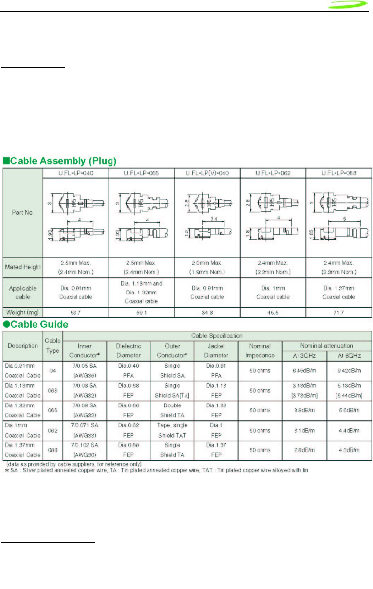
76
Novatel Wireless
Revision 1
Appendix D - Reference Parts Specifications
RF Connector
Hirose U.FL series, with U.FL-R-SMT receptacle mating to the following connectors illustrated.
Note that . This connector is designed for a limited number of insertions. For an embedded
application this is expected to be acceptable.
Figure 44: RF Connector
Mini Card Connector
Molex 67910 series, mates with the mini PCI Express Card. Use with Latch 48099-0003.
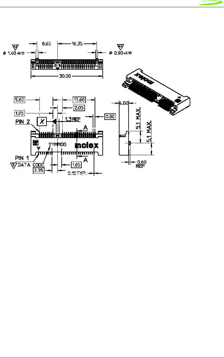
77
Novatel Wireless
Revision 1
Figure 45: Mini PCI Express Connector

80
Novatel Wireless
Revision 1
Appendix I - Glossary
Abbreviations given in 3GPP TR 21.905 [15] and the following] apply.
Access Point Name (APN)
The IP domain name (i.e. Novatel Wireless.com) of the network device that acts as a gateway by
connecting a CDMA wireless radio network to a wired local or wide area network.
Active Network Session
An active network session allows you to send and receive data across the Internet using point-to-
point protocol through your network connection.
Anonymous Access (AA)
Network does not know the real identity of the mobile. Opposite to non-anonymous.
AP Access Point
An entry point to an external network.
AT Commands
AT commands are a language type that enables PC communications software to give the modem
directions. The term AT comes from the command terminology which always begins with
attention, or AT.
Authentication Authorization Accounting (AAA)
Used as shared secret passwords during a Mobile IP registration.
Baud Rate
The actual bit rate, excluding compression and other TX enhancements, on a communication
line.
Border Gateway (BG)
Logical box that connects two (or more) operators together via an Inter-PLMN backbone. BG
protects operator’s intra-PLMN network against intruders.
Carrier
See Service Provider
Circuit Switched Data
A wireless network connection established, using a single circuit that extends from you, directly
through the network to your call’s destination. Opposite to packet switched.
CLI
Command Line Interface.
CLIR
Call Line Identification Restriction.
Code Division Multiple Access (CDMA)
Code Division Multiple Access is a spread spectrum wireless access technology that allows
multiple users to share the same physical RF channel (1.25MHz for single carrier direct spread
1X) by use of orthogonal code spreading.
Connection Oriented Network Service (CONS)
Same as X.25 protocol for packet network transmission and switching.

81
Novatel Wireless
Revision 1
Connection Profile
See Network Connection Profiles
CSD
See Circuit Switched Data
dBm
dBm stands for decibels below 1 milliwatt. It is essentially a device’s signal output power
compared against a standard input signal strength of 1 (one) milliwatt. This number represents a
ratio and is expressed as a negative number (i.e. -60dBm)
Default Network Connection Profile
The default network connection profile is the connection profile, chosen by you that the Modem
Manager will use to connect to the network. The default network connection profile can be
thought of as the active network connection profile.
Direct Memory Access (DMA)
A fast method of moving data from a storage device or LAN device interface card directly to RAM
which speeds up processing. DMA by passes the CPU.
Domain Name
The name assigned to a computer or group of computers that constitute an IP network domain. In
general, a domain name is comprised of its local host name and its top-level domain. The top-
level domain can be made up of several names, each separated by a period (.).
An example of a domain name is novatelwireless.com.
Domain Name System (DNS)
This is a network server used on IP networks, such as the Internet, for translating network host
names and Universal Resource Locators (URL’s) into IP addresses.
Domain Name System (DNS) Address
The IP (internet protocol) address of the Domain Name System (DNS).
Edge Technologies
Edge (Enhanced Data for Global Evolution) is an enhanced version of GPRS providing three to
four times more capacity and data throughput. Average speeds range from 100 to 130 kbps with
theoretical peak data rates of 473 kbps. Average rates are fast enough to support a wide range of
advanced data services such as streaming audio and video, fast Internet access and large file
downloads, EDGE can also support a greater range of enterprise applications, and more
multimedia applications including push-to-talk services.
EVPF
Enhanced Validity Period Format
Firmware
Firmware is a program or set of programs that have been set permanently into a computer chip.
The programs themselves usually are low-level programs that directly manipulate or interact with
the hardware. An example of firmware is your desktop computer’s BIOS.
General Packet Radio Service (GPRS)
GRPS is a packet-based, always-on data connection standard.
High Speed Downlink Packet Access (HSDPA)
HSDPA is a packet-based data service that improves upon UMTS by increasing speeds to 500-
800 kbps with peak data rates of up to 10 Mbps (five times faster than UMTS and other 3G
technologies) in a 5 Mhz channel. In addition, HSDPA significantly improves packet data
throughput capacity, thereby increasing the number of users that can be supported at higher data
rates on a single radio carrier.

82
Novatel Wireless
Revision 1
Home Agent (HA)
A router in the home subnet of the mobile node. Used in part with Mobile IP.
Home Public Land Mobile Network (HPLMN)
The home network.
IMEI
IMEI stands for International Mobile Station Equipment Identity.
Internet Protocol (IP)
Internet Protocol works in conjunction with Transmission Control Protocol (TCP). TCP/IP are part
of a group of protocols that provide communication across interconnected networks. TCP/IP is
the protocol used on the Internet. The TCP protocol first establishes a connection between the
two systems in order to send and receive data, and then breaks and sequentially marks the
message into small packets. The IP protocol routes and sends the packets based on the IP
address.
Internet Control Message Protocol (ICMP)
IP network control protocol.
Internet Over-The-Air (IOTA)
Network operators can remotely provision a device on their network by using an Internet Over-
The-Air implementation. Usually, a newly purchased device needs to initiate an IOTA session to
perform provisioning before it is allowed to be on the operator’s wireless network.
IP Addresses
As with personal computers that access the Internet, modems using CDMA technology also have
a dedicated Internet Protocol (IP) address, which is used to identify the node or access point for
the modem on the Internet. The service provider assigns this IP address.
The 32-bit host address is usually represented in dotted decimal notation, e.g. 128.121.4.5. The
address can be split into a network number (or network address) and a host number unique to
each host on the network and sometimes also a subnet address.
IP Network
A network of computer networks that employ Internet Protocol allowing a user to access the
Internet, provided that the user has a modem; telephone line, cable line, or wireless data network
(e.g. CDPD); and a service provider.
Local Area Network (LAN)
A computer network that spans a relatively small area (typically up to a 1 km radius), although
most LANS are confined to a single building or group of buildings. This type of networking allows
for easy interconnection of terminals, printers, and computers within a building or buildings.
Logical Link Control (LLC)
Protocol layer between MS and SGSN.
Medium Access Control (MAC)
Protocol in the radio level that is used to allocate the radio channel.
Megahertz (MHz)
One million hertz. Hertz is another word for cycles in a radio frequency.
Mobile Directory Number (MDN)
Mobile Identification Number (MIN)
Mobile IP (MIP)
Mobile IP provides a method to allow IP traffic to find nodes whose point of attachment to the
Internet changes.

83
Novatel Wireless
Revision 1
Mobile Node (MN)
This is either an application running on a handset, or a data device connected to a handset with
IP connectivity.
Mobile Station (MS)
The device being used to receive/transmit data and/or voice.
Mobile-Terminal (MT)
Network Access Identifier (NAI)
Used as an Identifier/login for Mobile IP.
Network Connection Profiles
A network connection profile is a group of connection settings that define a specific network
connection to the Modem Manager. This includes such settings as network ID, network
password, APN, DNS addresses and so on.
Novatel Wireless Inc. (NWI) (NVTL)
Original Equipment Manufacturer (OEM)
The original manufacturer of a pieces of equipment, typically complete boards, duplexers or
enclosures etc.
Over-The-Air (OTA)
Packet
A short block of data transmitted across a network.
Packet Data Network (PDN)
Network that carries user data in packets. ex. Internet and X.25
Packet Size
The size of a packet expressed in bytes.
PC Card
A PC Card, similar in size to a credit card, is used for adding devices on to portable computing
devices such as laptop, handheld, and palmtop computers. Some examples of these devices are
modems, network cards, disk drive adapters, and extra memory. PC cards are often called
PCMCIA cards.
Peripheral Component Interconnect Special Interest Group (PCI SIG)
PCMCIA Card Slots
The PCMCIA card slots are the sockets in the computing device, in which the PCMCIA card is
inserted. It is the hardware interface between the computing device and the PCMCIA card.
Point to Multipoint (PTM)
Widely used IP protocol used to connect, i.e. PC and ISP via modems.
Point to Point (PTP)
One sender on receiver.
Point-to-Point Protocol (PPP)
PPP is an interconnection protocol which allows a device, such as a wireless IP modem, to
connect to a network or the Internet.
Primary Domain Name System
In order to get the translated IP addresses, the modem will try to connect to the server with the
primary DNS address. If the modem cannot connect to this address, it will try to connect using the
secondary DNS address.

84
Novatel Wireless
Revision 1
Primary Roaming List (PRL)
Protocol Data Unit (PDU)
One data packet.
Quality of Service (QoS)
Definition of the service class of the connection between MS and the network.
Radio Link Protocol (RLP)
Registration
In order to send and receive data across a given network, a CDMA modem must first register to a
CDMA network. This involves the selection of an available channel and interaction with various
systems on the CDMA network to set up a communication path.
Remote Access Service (RAS)
Software that enables distant PCs and workstations to get into a Remote Access Server to
retrieve software and/or data on a corporate LAN. This service is provided through modems,
analog telephone lines or digital ISDN lines.
Routing Area (RA)
A set of cells that belongs to one group. RA is always a subset of an LA (Location Area).
Secondary Domain Name System
If the modem cannot connect to the DNS using the primary address, it will try to connect using the
secondary DNS address.
Security Parameter Index (SIP)
Used in part with Mobile IP.
Segment
Each IP network address consists of four numeric segments, which are divided by a period (".").
For example, 204.119.63.40.
Service Provider
A company that provides network connections to the Internet.
Short Message Service (SMS)
Short messages either in binary (160 characters) or text messages (140 bytes) format.
Terminal Equipment (TE)
Transmission Control Protocol (TCP)
Protocol layer on top of conventional IP protocol.
Type II PCMCIA Card
A Type II PCMCIA card is identical to the Type I PCMCIA card in all ways except that it is thicker
than the Type I card. The Type II PCMCIA card is in general use now.
Um
Mobile-to-Base Station air interface link.
Universal Product Support Tool (UPST)
The Universal Product Support Tool (UPST) consists of the UPST Framework and UPST device
DLLs. The UPST Framework is a Windows 32 application (UPST.exe) that uses UPST device
Dynamic Link Libraries (DLLs) to provide basic device provisioning functions such as Refurbish,
Software upgrades, Preferred Roaming List (PRL) upgrades, and Phone Settings programming.
User Datagram Protocol (UDP)
Another protocol on top of IP.

85
Novatel Wireless
Revision 1
Wireless IP Network
A wireless network (e.g. CDMA) that uses Internet Protocol (IP)