Novatel Wireless NVWE362 Cellular/PCS/GSM/EDGE/WCDMA/CDMA&700MHz LTE Module User Manual OEM Integration
Novatel Wireless Inc Cellular/PCS/GSM/EDGE/WCDMA/CDMA&700MHz LTE Module OEM Integration
Contents
User Manual - OEM Integration
GM.90026573
Rev 1
OEM INTEGRATION
GUIDE – E362
Guidelines for System Integration

GM.90026573 OEM INTEGRATION GUIDE – E362
Proprietary and Confidential
Novatel Wireless © 2011 Rev 1 1
Notice: Restricted Proprietary Information and subject to the confidentiality restrictions contained
in any applicable non-disclosure agreement.
© Copyright Novatel Wireless, Inc. (2011)
The information contained in this document is the exclusive property of Novatel Wireless, Inc. All
rights reserved. Unauthorized reproduction of this manual in any form without the expressed
written approval of Novatel Wireless, Inc. is strictly prohibited. This manual may not, in whole or in
part, be copied, reproduced, translated, or reduced to any electronic or magnetic storage medium
without the written consent of a duly authorized officer of Novatel Wireless, Inc.
The information contained in this document is subject to change without notice and should not be
construed as a commitment by Novatel Wireless, Inc. unless such commitment is expressly given
in a document.
Novatel Wireless, Inc. makes no warranties, either expressed or implied, regarding this
document, its merchantability, or its fitness, for any particular purpose.
Legal Disclaimer
This document and the information contained in the E362 LTE Modem Guidelines for System
Integration (together, the “Information”) is provided to you by Novatel Wireless for informational
purposes only.
Novatel Wireless is providing the Information to you because Novatel Wireless believes that the
information in this document would be helpful to you during the Integration of the E362 modem on
to your host platform. This Information is provided on the condition that you will be responsible for
making your own assessments of the information and you are advised to verify all
representations, statements and information obtained from this document before using them or
relying upon them. Although Novatel Wireless believes that it has exercised reasonable care in
providing the Information, Novatel Wireless does not warrant the accuracy of the Information and
is not responsible for any damages arising from its use or reliance upon the Information. You
further understand and agree that Novatel Wireless in no way represents, and you in no way rely
on a belief, that Novatel Wireless is providing the information in accordance with any standard or
service (routine, customary or otherwise) related to the consulting, services, hardware or software
industries.
GM.90026573 OEM INTEGRATION GUIDE – E362
Proprietary and Confidential
Novatel Wireless © 2011 Rev 1 2
NOVATEL WIRELESS DOES NOT WARRANT THAT THE INFORMATION IS ERROR FREE.
NOVATEL WIRELESS IS PROVIDING THE INFORMATION TO YOU "AS IS" AND "WITH ALL
FAULTS." NOVATEL WIRELESS DOES NOT WARRANT, BY VIRTUE OF THIS DOCUMENT,
OR BY ANY COURSE OF PERFORMANCE, COURSE OF DEALING, USAGE OF TRADE OR
ANY COLLATERAL DOCUMENT HEREUNDER OR OTHERWISE, AND HEREBY EXPRESSLY
DISCLAIMS, ANY REPRESENTATION OR WARRANTY OF ANY KIND WITH RESPECT TO
THE INFORMATION, INCLUDING, WITHOUT LIMITATION, ANY REPRESENTATION OR
WARRANTY OF DESIGN, PERFORMANCE, MERCHANTABILITY, FITNESS FOR A
PARTICULAR PURPOSE OR NON INFRINGEMENT, OR ANY REPRESENTATION OR
WARRANTY THAT THE INFORMATION IS APPLICABLE TO OR INTEROPERABLE WITH ANY
SYSTEM, DATA, HARDWARE OR SOFTWARE OF ANY KIND.
NOVATEL WIRELESS DISCLAIMS AND IN NO EVENT SHALL BE LIABLE FOR ANY LOSSES
OR DAMAGES OF ANY KIND, WHETHER DIRECT, INDIRECT, INCIDENTAL,
CONSEQUENTIAL, PUNITIVE, SPECIAL OR EXEMPLARY, INCLUDING, WITHOUT
LIMITATION, DAMAGES FOR LOSS OF BUSINESS PROFITS, BUSINESS INTERRUPTION,
LOSS OF BUSINESS INFORMATION, LOSS OF GOODWILL, COVER, TORTIOUS CONDUCT
OR OTHER PECUNIARY LOSS, ARISING OUT OF OR IN ANY WAY RELATED TO THE
PROVISION, NON PROVISION, USE OR NON USE OF THE INFORMATION, EVEN IF YOU
HAVE BEEN ADVISED OF THE POSSIBILITY OF SUCH LOSSES OR DAMAGES.
GM.90026573 OEM INTEGRATION GUIDE – E362
Proprietary and Confidential
Novatel Wireless © 2011 Rev 1 3
Table of Contents
REVISION TABLE ................................................................................................ 6
REFERENCE DOCUMENTS ................................................................................ 7
NOTICES .............................................................................................................. 9
Safety Warning ............................................................................................................................... 9
1. OVERVIEW OF LTE MODULE E362 ............................................................. 11
2. MODULE SPECIFICATION ............................................................................ 13
2.1 Mechanical Specification ...................................................................................................... 13
2.2 Electrical Specification ......................................................................................................... 14
2.2.1 PCIe Interface .................................................................................................................. 14
2.2.2 W_DISABLE# Interface ................................................................................................... 15
2.2.3 WAKE# Interface ............................................................................................................. 16
2.2.4 USB Interface .................................................................................................................. 17
2.2.5 LED_WWAN# ................................................................................................................... 17
2.2.6 Subscriber Identification Module (SIM) Interface ........................................................ 17
2.2.7 Power Supply .................................................................................................................. 17
2.3 Specification for RF sub system .......................................................................................... 17
2.3.1 Antenna Connector ......................................................................................................... 17
2.3.2 Primary and Diversity antennas .................................................................................... 18
2.3.3 GPS ................................................................................................................................... 18
2.4 Environmental Specification and Compliance ................................................................... 19
2.5. Regulatory Approval and Compliance ............................................................................... 19
2.5.1 FCC (Federal Communication Commission) ............................................................... 19
2.5.2 Labeling Notice for End Use Products ......................................................................... 20
2.5.3 CE (Conformance European) ......................................................................................... 20
3. GUIDELINES FOR MODULE HARDWARE INTEGRATION ......................... 22
3.1 Radiation Related Performance Parameters ...................................................................... 22
3.1.1 Total Radiated Power (TRP) ........................................................................................... 22
3.1.2 Total Isotropic Sensitivity (TIS) ..................................................................................... 24
3.1.3 Guidelines for Obtaining Good RF Performance of the Module ................................ 26
3.2 Guidelines for integration of SIM ......................................................................................... 28
3.2.1 Description of SIM .......................................................................................................... 28
3.2.2 Typical Interface Design for the SIM ............................................................................. 29
3.2.3 Description of Signals .................................................................................................... 29
GM.90026573 OEM INTEGRATION GUIDE – E362
Proprietary and Confidential
Novatel Wireless © 2011 Rev 1 4
3.3 Guidelines for Integration of SMBus ................................................................................... 32
3.4 Guidelines Related to USB interface ................................................................................... 34
4. GETTING STARTED WITH DEVELOPMENT ................................................ 35
4.1 General ................................................................................................................................... 35
4.2 How to Set Up ........................................................................................................................ 35
5. HOST SOFTWARE ........................................................................................ 42
5.1 Drivers .................................................................................................................................... 42
5.2 NovaCore SDK ....................................................................................................................... 42
5.3 MobiLink 3™ Connection Manager ..................................................................................... 43
5.4 Novaspeed™ .......................................................................................................................... 45
APPENDIX A - COMPLIANCE WITH REGULATORY STANDARDS ............... 46
A.1 FCC Requirements Related to Radio Interference ............................................................ 46
A.2 FCC Requirements Related to Exposure to Radio Frequencies ...................................... 46
A.3 Requirements of CE .............................................................................................................. 46
A.4 Requirements of R&TTE ....................................................................................................... 47
A.5 Requirements of PCS Type Certification Review Board (PTCRB) ................................... 47
A.6 Requirements of Global Certification Forum (GCF), ......................................................... 47
A.7 Conformance with the Windows Certified Platforms ........................................................ 48
APPENDIX B - SPECIFICATION OF PARTS .................................................... 49
B.1 RF Connector ........................................................................................................................ 49
B.2 Mini Card Connector ............................................................................................................. 50
APPENDIX C - GLOSSARY ............................................................................... 51
GM.90026573 OEM INTEGRATION GUIDE – E362
Proprietary and Confidential
Novatel Wireless © 2011 Rev 1 5
List of Figures
Figure 1: Mechanical Dimensions ................................................................................................. 13
Figure 2: Antenna Connector Locations ........................................................................................ 14
Figure 3: W_DISABLE# Pull-up Configuration .............................................................................. 15
Figure 4: WAKE# Configuration .................................................................................................... 16
Figure 5: SIM Contact Locations (viewed from contact side) ........................................................ 29
Figure 6: Typical Connection between SIM Connector and PCIe Edge Connector ...................... 31
Figure 7: Modem Interface Board and Cables .............................................................................. 36
Figure 8: Phone and Modems Options Window ............................................................................ 37
Figure 9: Device Manager Window Showing the Computer’s Active COM Ports ......................... 38
Figure 10: HyperTerminal Connection Description Window ......................................................... 39
Figure 11: HyperTerminal COM Port Selection Window ............................................................... 39
Figure 12: HyperTerminal Properties Window .............................................................................. 40
Figure 13: HyperTerminal Communication Window ...................................................................... 41
Figure 14: Block Diagram of Driver Components on Host ............................................................ 42
Figure 15: Integration of Software Application Using NovaCore SDK .......................................... 43
Figure 16: MobiLink™ in the Context of NovaCore ....................................................................... 44
Figure 17: RF Connector ............................................................................................................... 49
Figure 18: Mini Card Connector .................................................................................................... 50
List of Tables
Table 1: Supported Technologies and Frequency Bands ............................................................. 11
Table 2: PCIe Pinout ..................................................................................................................... 14
Table 3: DC Specification for 3.3V Logic Signaling ....................................................................... 16
Table 4: WAKE# Requirements ..................................................................................................... 17
Table 5: E362 Environmental Specification ................................................................................... 19
Table 6: R&TTE Requirements ..................................................................................................... 20
Table 7: 3GPP Requirements ........................................................................................................ 21
Table 8: Example of Estimated TRP ............................................................................................. 23
Table 9: Example of Estimated TRP and Carrier Specified Minimum TRP .................................. 24
Table 10: Example of Estimated TIS ............................................................................................. 25
Table 11: Example of Estimated TIS and Carrier Specified Minimum TIS .................................... 26
Table 12: SIM Interface Signals .................................................................................................... 29
Table 13: VCC Voltage Levels ...................................................................................................... 30
Table 14: RST Electrical Requirements ........................................................................................ 30
Table 15: CLK Electrical Requirements ........................................................................................ 30
Table 16: I/O Electrical Requirements ........................................................................................... 31

GM.90026573 OEM INTEGRATION GUIDE – E362
Proprietary and Confidential
Novatel Wireless © 2011 Rev 1 6
Revision Table
ECO Revision Date By Remark
11449 1 13 September 2011 Daryl Therens First release
GM.90026573 OEM INTEGRATION GUIDE – E362
Proprietary and Confidential
Novatel Wireless © 2011 Rev 1 7
Reference Documents
[1] PCI Express Mini Card Electromechanical Specification, Revision 1.2, October 26, 2007.
[2] PCI Express Card Electromechanical Specification revision 1.1 March 28th 2005
[3] SMBus Specification, Revision 2.0
[4] The I2C BUS SPECIFICATION Version 2.1 January 2000
[5] TS 36 series specifications on LTE http://www.3gpp.org/ftp/Specs/html info/36 series.htm
[6] 3GPP TS 01.04: "Abbreviations and acronyms".
[7] 3GPP TS 11.11: “Specification of the Subscriber Identity Module Mobile Equipment (SIM
ME) interface”.
[8] 3GPP TS 11.12: "Specification of the 3 Volt Subscriber Identity Module Mobile Equipment
(SIM ME) interface".
[9] 3GPP TS 11.18: “Specification of the 1.8 Volt Subscriber Identity Module Mobile
Equipment (SIM ME) interface”.
[10] 3GPP TS 51.010 1 “Mobile Station (MS) conformance specification; Part 1: Conformance
specification”.
[11] 3GPP TS 23.040: "Technical realization of the Short Message Service (SMS) ".
[12] 3GPP TS 23.041: "Technical realization of the Cell Broadcast Service (CBS)".
[13] 3GPP TS 24.008: "Mobile Radio Interface Layer 3 specification; Core Network Protocols;
Stage 3".
[14] 3GPP TS 24.011: "Short Message Service (SMS) support on mobile radio interface".
[15] 3GPP TS 24.012: "Cell Broadcast Service (CBS) support on the mobile radio interface".
[16] 3GPP TS 27.001: "General on Terminal Adaptation Functions (TAF) for Mobile Stations
(MS)".
[17] 3GPP TS 27.007: "AT command set for User Equipment (UE)".
[18] 3GPP TS 51.011: "Specification of the Subscriber Identity Module Mobile Equipment (SIM
ME) interface".
[19] ITU T Recommendation V.25ter: "Serial asynchronous automatic dialing and control".
[20] ITU T Recommendation V.24: "List of definitions for interchange circuits between data
terminal equipment (DTE) and data circuit terminating equipment (DCE)".
[21] ITU T Recommendation E.164: "The international public telecommunication numbering
plan".
[22] ITU T Recommendation E.163: "Numbering plan for the international telephone service".
[23] 3GPP TR 21.905: "Vocabulary for 3GPP Specifications".
[24] 3GPP TS 31.102: "Characteristics of the USIM application.
[25] 3GPP TS 23.038: "Alphabets and language specific information".
[26] High Speed USB Platform Design Guidelines, Intel, Rev. 1.0, dt. 07/12/2000,
[27] 3GPP TS 11.12: "Specification of the 3 Volt Subscriber Identity Module Mobile
Equipment (SIM ME) interface".
GM.90026573 OEM INTEGRATION GUIDE – E362
Proprietary and Confidential
Novatel Wireless © 2011 Rev 1 8
[28] 3GPP TS 11.18: “Specification of the 1.8 Volt Subscriber Identity Module Mobile
Equipment (SIM ME) interface”.
[29] 3GPP TS 51.010 1 “Mobile Station (MS) conformance specification; Part 1: Conformance
specification”.
[30] ISO/IEC 7816 1: “Identification cards – Integrated circuit cards with contacts – Part 1:
Physical characteristics”.
[31] ISO/IEC 7816 2: “Identification cards – Integrated circuit cards with contacts – Part
2:Dimensions and locations of the contacts.
[32] ISO/IEC 7816 3 “Identification cards – Integrated circuit cards with contacts – Part 3:
Electronic signals and transmission protocols”.
[33] Compliance Test Plan: LTE over the air Radiated Performance, version 6.0, Verizon
Wireless, September 2010.

GM.90026573 OEM INTEGRATION GUIDE – E362
Proprietary and Confidential
Novatel Wireless © 2011 Rev 1 9
Notices
Safety Warning
The E362 modem may not be used in an environment where radio frequency equipment is
prohibited or restricted in its use. This includes aircrafts, airports, hospitals, and other sensitive
electronic areas.
Do not operate RF devices in an environment that may be susceptible to radio interference
resulting in danger, specifically:
• Areas where prohibited by the law
Follow any special rules and regulations and obey all signs and notices. Always
turn off the host device when instructed to do so, or when you suspect that it may
cause interference or danger.
• Where explosive atmospheres may be present
Do not operate your modem in any area where a potentially explosive
atmosphere may exist. Sparks in such areas could cause an explosion or fire
resulting in bodily injury or even death. Be aware of and comply with all signs and
instructions.
• Users are advised not to operate the modem while they are at a refueling point or
service station.
Users are reminded to observe restrictions on the use of radio equipment in fuel
depots (fuel storage and distribution areas), chemical plants or where blasting
operations are in progress.
• Areas with a potentially explosive atmosphere are often but not always clearly
marked.
Potential locations can include gas stations, below deck on boats, chemical
transfer or storage facilities, vehicles using liquefied petroleum gas (such as
propane or butane), areas where the air contains chemicals or particles, such as
grain, dust or metal powders, and any other area where you would normally be
advised to turn off your vehicle engine.
• Near Medical and life support equipment
Do not operate your modem in any area where medical equipment, or life support
equipment may be located, or near any equipment that may be susceptible to
any form of radio interference. In such areas, the host communications device
must be turned off. The modem may transmit signals that could interfere with this
equipment.
• On an aircraft, either on the ground or airborne
In addition to FAA requirements, many airline regulations state that you must
suspend wireless operations before boarding an airplane. Please ensure that the
host device is turned off prior to boarding an aircraft in order to comply with
these regulations. The modem can transmit signals that could interfere with
various onboard systems and controls.
• While operating a vehicle
The driver or operator of any vehicle should not operate a wireless data device.
Doing so will detract from the driver or operator's control and operation of that
GM.90026573 OEM INTEGRATION GUIDE – E362
Proprietary and Confidential
Novatel Wireless © 2011 Rev 1 10
vehicle. In some countries, operating such communication devices while in
control of a vehicle is an offence.
Under extended operation, the E362 modem will generate a noticeable amount of heat. This
modem generates heat during normal operation and will be heated by the host computer. For this
reason, it is recommended that after extended periods of operation of this modem, you allow the
modem to cool down prior to removal and handling.

GM.90026573 OEM INTEGRATION GUIDE – E362
Proprietary and Confidential
Novatel Wireless © 2011 Rev 1 11
1. Overview of LTE Module E362
The E362 modem is part of the Novatel Wireless’ Expedite® PCI Express Mini Card family of
modules. This module is capable of providing the terminal side interface of an LTE Network. The
modem is designed to support the LTE terminal devices to be connected primarily to the Verizon
Wireless Network in the U.S.A. In addition to LTE, the E362 modem supports 3G and 2G wireless
technologies such as HSPA+ / EDGE / GPRS, CDMA EVDO DO Revision 0 and Revision A, and
CDMA 1xRTT. The modem has been developed to be integrated into devices such as Notebook
PCs, Notebook Tablet PCs, hand held devices, etc., and are based on the PCI Express Mini card
specification 1.2 [1].
Following are the bands in which the E362 module is operational for each wireless technology.
Table 1: Supported Technologies and Frequency Bands
System Band Band Name Uplink (MHz) Downlink (MHz)
CDMA BC0 Cellular 824 – 849 869 - 894
BC1 pcs 1850 – 1910 1930 - 1990
GPRS/EDGE
850 Cellular 824 – 849 869 – 894
900 900 880.0 – 914.8 925.0 – 959.8
1800 DCS 1710.2 – 1784.8 1805.2 – 1879.8
1900 PCS 1850 – 1910 1930 – 1990
HSPA+
V Cellular 824 – 849 869 – 894
VIII 900 880 – 915 925 – 960
II PCS 1850 – 1910 1930 – 1990
I IMT 1920 – 1980 2110 – 2170
LTE XIII Verizon 700 777 – 787 746 – 756
GPS L1 GPS NA 1565.19 – 1585.65
L1 Glonass 1598.06 – 1605.94
The design of the module is based on the MDM9600 chipset of Qualcomm™. This chipset
supports Equalizer and Receive Diversity technologies. The Equalizer technology reduces the
inter symbol interference caused by multi paths. The receiver diversity helps to retrieve signals
under deep fades caused by multi paths.
The E362 modem is compatible with Microsoft Windows™ compliant applications including VPN,
email, and web browsing. The core protocol stack of this modem is supplied by Qualcomm™ and
it contains software modules for supporting LTE, UMTS, HSDPA, GPRS/EDGE and CDMA
technologies. Around this core, Novatel Wireless has created Firmware Drivers that provide
access for the host to the hardware of the embedded modem. Accordingly, the feature set of the
modem comprise data device features supported in the Qualcomm™ protocol stack and the
features implemented by Novatel Wireless in the Drivers. The list of key features is as follows:
• LTE
• HSDPA/UMTS
• EDGE/GPRS class 12
• Quad band GPRS/EDGE 850/900/1800/1900
• CDMA 1xRTT, EVDO Rev. 0, and Rev. A
GM.90026573 OEM INTEGRATION GUIDE – E362
Proprietary and Confidential
Novatel Wireless © 2011 Rev 1 12
• GPS
• SIM/USIM
• MobiLink™ and SDK available for third party dashboards
The hardware of the module consists of a PCI Express Mini Card compliant interface (except for
certain customizations required by vendors as described later in this document). The major parts
assembled on this card are a baseband chipset and an RF chipset, both of Qualcomm™,
together with various other components used in the design of the modem using these major
parts.
The purpose of this document is to provide information on the hardware, the firmware and the
drivers of the E362 modem. This document also provides information on certain Application
Programs which the customers of this modem may or may not make use of. The information
available in this document will be helpful to begin the evaluation of the E362 modem, and the
subsequent successful integration into host platforms.
GM.90026573 OEM INTEGRATION GUIDE – E362
Proprietary and Confidential
Novatel Wireless © 2011 Rev 1 13
2. Module Specification
As was described in the previous Section, the E362 modem has been designed in accordance
with the PCI Express Mini Card Specification 1.2 [1]. The governing body for PCI Express
standardization is PCI SIG (Peripheral Component Interconnect Special Interest Group).The
website for PCI SIG can be found at the following URL: www.pcisig.com/home
The E362 modem provides platform developers and system integrators with the ability to enable
4G/3G/2G wireless broadband access. The modem you have obtained may have undergone
certain customization specific to your requirement. These customizations are carried out with
respect to certain reserved pins as specified in the PCI Express Mini Card Specification. By using
these reserved pins, a user of the customized modem may be able to implement certain functions
that are outside the scope of the PCI Express Mini Card specification. In that respect, the
specification of the modem module you have obtained might differ from the generic specification
of the E362 modem.
The important topics of the specification required for the integration of this modem into host
devices are given below:
2.1 Mechanical Specification
The E362 modem meets the form factor as specified by the PCI Express Full Mini Card
Electromechanical Specification Revision 1.2 Type F2.
Figure 1: Mechanical Dimensions
GM.90026573 OEM INTEGRATION GUIDE – E362
Proprietary and Confidential
Novatel Wireless © 2011 Rev 1 14
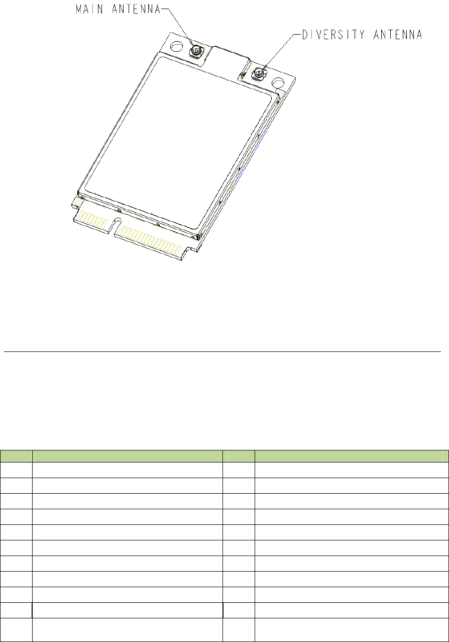
Figure 2: Antenna Connector Locations
Figure 1 indicates the mechanical dimensions and Figure 2 shows antenna connector locations.
2.2 Electrical Specification
2.2.1 PCIe Interface
The Table below gives a description of the pin out and the signal description.
Table 2: PCIe Pinout
Pin# Function Pin# Function
51 No Connect or GPS_DISABLE# (note 1) 52 +3.3Vaux
49 (No Connect) 50 GND
47 (No Connect) 48 (No Connect)
45 (No Connect) 46 (No Connect)
43 GND 44 (No Connect)
41 +3.3Vaux 42 LED_WWAN#
39 +3.3Vaux 40 GND
37 GND 38 USB_D+
35 GND 36 USB_D-
33 (No Connect) 34 GND
31 (No Connect) 32
SMB_DATA or No Connect or GPIO_C1
(note 1)
GM.90026573 OEM INTEGRATION GUIDE – E362
Proprietary and Confidential
Novatel Wireless © 2011 Rev 1 15
Pin# Function Pin# Function
29 GND 30
SMB_CLK or No Connect or GPIO_C2
(note 1)
27 GND 28 (No Connect)
25 (No Connect) 26 GND
23 (No Connect) 24 +3.3Vaux
21 GND 22 (No Connect)
19 (No Connect) 20 W_DISABLE#
17 (No Connect) 18 GND
Mechanical Key
15 GND 16 (No Connect)
13 (No Connect) 14 UIM_RESET
11 (No Connect) 12 UIM_CLK
9 GND 10 UIM_DATA
7 (No Connect) 8 UIM_PWR
5 (No Connect) 6 (No Connect)
3 (No Connect) 4 GND
1 No Connect or WAKE# 2 +3.3Vaux
Note 1: Contact Novatel Wireless for details.
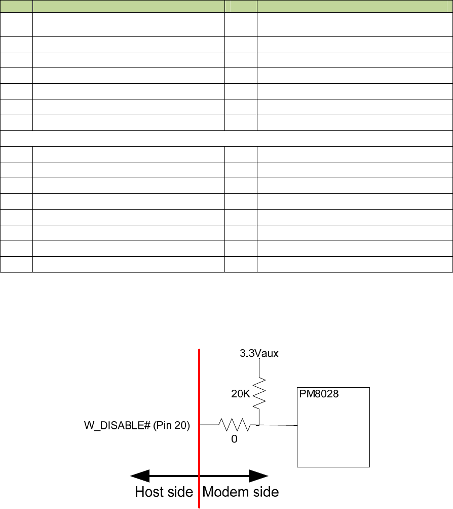
2.2.2 W_DISABLE# Interface
The Figure below shows the modem pull-up resistor configuration for the W_DISABLE# pin.
Figure 3: W_DISABLE# Pull-up Configuration
The W_DISABLE# signal from the host interface connector (pin 20) is used to control the
operational status of the radio transmitter. When it is high, the radio is capable of transmitting.
When it is low, the radio is made incapable of transmitting by removing the various power
supplies.
When the host asserts the W_DISABLE# signal low, an interrupt is generated which executes
power down routines such as saving any required data. The software programs the power
management device (PM8028) to selectively disable voltage regulators in order to render the
modem incapable of transmitting.
GM.90026573 OEM INTEGRATION GUIDE – E362
Proprietary and Confidential
Novatel Wireless © 2011 Rev 1 16
The assertion and de-assertion of W_DISABLE# is asynchronous to any system clock.
The modem meets the logic signal requirements as defined in Table 3-7 of the PCI Express Mini
Card Specification 1.2 [1]. The table below is shown for reference, and lists the 3.3V card logic
levels for the W_DISABLE# signal.
Table 3: DC Specification for 3.3V Logic Signaling
Symbol Parameter Conditions Min Max UnitsNotes
+3.3Vaux Supply Voltage 3.3 – 9% 3.3 + 9% V 1
VIH Input High Voltage 1.95 3.6 V
VIL Input Low Voltage -0.5 0.8 V
IIN Input Leakage Current 0V to 3.3V -10 +10 µA
ILKG Output Leakage Current 0V to 3.3V -50 +50 µA
CIN Input Pin Capacitance 7 pF
NOTES:
1. As measured at the card connector pad.
2. The W_DISABLE# signal is falling edge triggered.
3. The W_DISABLE# signal cannot be driven high if the module is not powered.
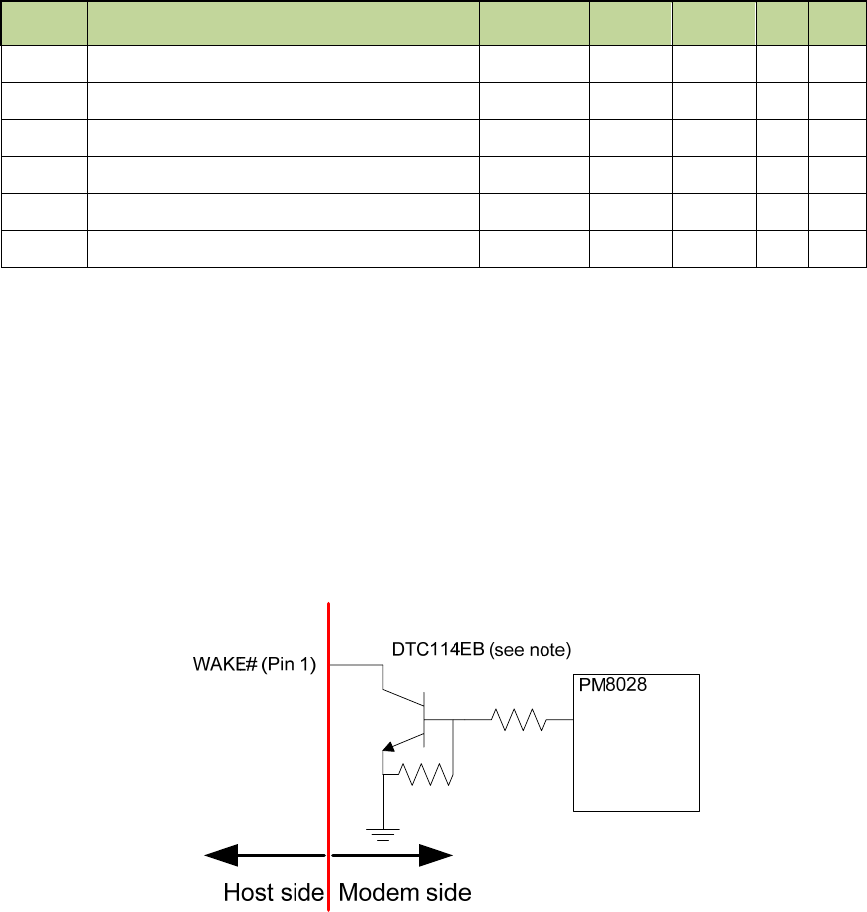
2.2.3 WAKE# Interface
The WAKE# signal is an open collector, active low signal. It is used to request that the host
system return from a sleep/suspended state to service a function initiated wake event.
If the wakeup process is implemented in the host platform, a host pull-up resistor (≥ 5kΩ
recommended) tied to no higher than +3.3Vaux is required on this pin. The Figure below shows
the modem configuration.
Figure 4: WAKE# Configuration
NOTE to Figure 4: The DTC114EB device may be changed to an equivalent device without prior
notice. Contact Novatel Wireless for details.

GM.90026573 OEM INTEGRATION GUIDE – E362
Proprietary and Confidential
Novatel Wireless © 2011 Rev 1 17
The assertion and de-assertion of WAKE# is asynchronous to any system clock.
Refer to Table 4 for logic signal requirements for the WAKE# signal.
Table 4: WAKE# Requirements
Symbol Parameter ConditionsMin Max Units Notes
VOH High level output
voltage
+3.3V_au
x
V
Connects to an open collector
transistor inside the E362
device
VOL Low level output voltage 0 0.5 V
IOL Output Low Current for
open-drain signals 0.4V 4 mA
COUT Output Pin Capacitance 30 pF
2.2.4 USB Interface
The device supports USB 2.0 Hi Speed mode.
2.2.5 LED_WWAN#
This pin (titled LED_WWAN_N) is connected to MPP_04 of the PM8028. This is connected to pin
42 of the PCIe connector. The output should be configured to drive from the 3V3 voltage rail. This
output is limited to sourcing or sinking +3mA/-3mA. Therefore, it must not directly drive an LED.
The modem design by default assumes that this signal drives the gate of a PFET in series with an
LED. This signal is active low, and the signal will turn on the LED when a logic state “0” is applied
to the pin
2.2.6 Subscriber Identification Module (SIM) Interface
The SIM will be hosted on the host motherboard. A SIM cannot be hosted on the E362 module. A
4 pin SIM interface connector is available on the Mini Card edge connector of the E362 modem.
The SIM is also known as Universal SIM (USIM) in 3GPP networks and Removable SIM (RSIM)
in 3GPP2 networks. The SIM interface at the edge connector of E362 will support 1.8V USIMs,
3.0V USIMs and 3.0V SIMs. Please see Section 3.2 for guidelines for the integration of the SIM.
Hot-swapping of SIMs is not supported.
2.2.7 Power Supply
The E362 modem is fully operational when the range of the input voltage is 3.3V ± 9%.
2.3 Specification for RF sub system
2.3.1 Antenna Connector
The positions of the antenna connectors of the E362 are indicated in Figure 2. This modem is
designed to be connected to an external antenna (integrated into the host system). The antenna
ports present nominal 50Ω impedance to the external antenna.
GM.90026573 OEM INTEGRATION GUIDE – E362
Proprietary and Confidential
Novatel Wireless © 2011 Rev 1 18
The TX and primary RX connection is present on the main connector.
The Diversity RX and GPS connection is present on the Aux connector.
The antenna connectors are Hirose U.FL R SMT or equivalent. Please note that these connectors
are designed for a limited number of insertions and removals (30 cycles, maximum).
2.3.2 Primary and Diversity antennas
The RF performance is heavily dependent on the selection and placement of antennas. The
antennas shall be chosen in accordance with the following considerations:
• The antennas shall have a nominal impedance of 50Ω for all the bands they support.
• The return loss shall be ≤ 10 dB throughout the range of all frequency bands of operation.
• The antenna gain may be such that the system shall satisfy the radiation limits for maximum
power and regulatory requirements. For example, usually the antenna solution may require a
compromise between achieving maximum power and compliance with the SAR requirements.
The module is sufficiently shielded so as to reduce the direct effect of radiation. However, indirect
effect may arise if the traces or connector pins are affected by the radiation. The antenna location
should be chosen such that the radiation does not affect either the host system or the module.
2.3.3 GPS
GPS is supported by the E362 module. The antenna for receiving the GPS signal is the auxiliary
antenna (Please see Figure 2.). The module will support the following GPS features, provided
that the associated application and the Network also support the operation of the features
identified below.
GPS Features
• GPS Standalone mode (without assistance from the Network).
• GPS MS Based (Mobile Station based) gives fast fix and better sensitivity. Requires periodic
support from PDE (Position Determining Entity). in 3GPP Networks, PDE’s counterparts are
GMLC (Gateway Mobile Location Center) and Serving Mobile Location Center (SMLC),
• GPS MS Assisted best coverage and best accuracy. Requires constant PDE support.
GPS Application Services
• Simultaneous GPS fix and data session. Autonomous GPS with caching of ephemeris and
last fix.
• Interfaces
– Serial NMEA interface pass through MobiLink 3™ or NovaCore API for location
request and tracking.
– SMS Activated Location Responder
– GPS Timer and Fencepost trigger
• Applications
– Common GPS/LBS client on host device.
– Popular Adapters to Browser, Map, Traffic & POI client apps.
– Vertical Market Subsystem enabler – client tracking & fixing.
– Possible Location Server / Dispatch Assist.

GM.90026573 OEM INTEGRATION GUIDE – E362
Proprietary and Confidential
Novatel Wireless © 2011 Rev 1 19
2.4 Environmental Specification and Compliance
The E362 modem complies with the PCI Express Full Mini Card Revision 1.2 Type F2 standards.
The modem will meet the limits indicated in Table 5.
It should be noted that Novatel Wireless cannot guarantee that the host device (Laptop PCs,
PDA, Notebook PC etc.) will be able to endure these same environmental conditions. Users are
advised to consult the host device specifications and observe any restrictions of use.
The modem will withstand a 75cm drop to a hard surface and still remain functional.
Electrostatic Discharge and Electro Magnetic Interference
The modem does not provide ESD protection at the antenna connectors or edge connectors. It is
the responsibility of the host platform to ensure that there will not be any harmful discharges to
the modem.
Table 5: E362 Environmental Specification
Parameter Value of limit
Low Temperature Storage -40°C
High Temperature Storage 85°C
Low Temperature Operating -20°C
High Temperature Operating 65°C
Relative Humidity 95% maximum (non-condensing)
Vibration and High Frequency 147m/s2 (3Grms) peak; 5 to 5000 Hz random
Drop 75 cm
With regards to EMI, the E362 modem meets FCC part 15 for North American markets, and ETSI
EN 301489-1 for European markets. When this modem is integrated into a UE, the UE requires
approvals of regulatory authorities (FCC for example).
2.5. Regulatory Approval and Compliance
2.5.1 FCC (Federal Communication Commission)
With reference to safety; health, environment and consumer protection, the E362 modem
complies, for the applicable band, with the following parts of the Federal Communication
Commission’s (FCC) Code of Federal Regulations (CFR):
FCC CFR47 Part 2; Frequency Allocations and Radio Treaty Matters; General Rules and
Regulations; Radio Frequency Radiation Exposure Evaluation
FCC CFR47 Part 15; Radio Frequency Devices
FCC CFR47 Part 22; Public Mobile Services
FCC CFR47 Part 24; Personal Communications Services
FCC CFR47 Part 27; Miscellaneous Wireless Communications Services

GM.90026573 OEM INTEGRATION GUIDE – E362
Proprietary and Confidential
Novatel Wireless © 2011 Rev 1 20
An FCC grant shall be obtained by the UE in order to demonstrate compliance.
2.5.2 Labeling Notice for End Use Products
For any end use product that the Novatel modem is used in, a label containing the following
information must be placed visibly on the outside of the product, as applicable.
This device contains FCC ID: PKRNVWE362 and IC: 3229B:E362
2.5.3 CE (Conformance European)
The E362 modem complies with the essential requirements of all of the applicable European laws
and directives with respect to safety, health, environment, and consumer protection. This modem
conforms to the essential requirements of the R&TTE (Radio and Telecommunications Terminal
Equipment) Directive, 1999/5/EC, and has the CE mark affixed. The applicable sections of the
following standards have been used to demonstrate compliance to this requirement.
Table 6: R&TTE Requirements
R&TTE
Requirement Discipline Definition Applied Standard
Article 3.1(a) Health Safety Testing ICNIRP 19981 European
Council Rec.1999/519 EC
Article 3.1(a) Safety IEC 60950 12
Article 3.1(b) EMC
EMC testing
(unintentional radiators, etc.)
EN 301 489 013
EN 301 489 074
EN 301 489 245
Article 3.2 Spectrum Network Testing (power,
frequency stability, etc.)
EN 301 5116
EN 301 908 17
1 International Commission on Non Ionizing Radiation Protection
2 Safety of Information Technology Equipment
3Electromagnetic compatibility and Radio Spectrum Matters (ERM) ElectroMagnetic Compatibility
( EMC) standard for radio equipment and services
Part 1: Common Technical requirements
4Electromagnetic compatibility and Radio Spectrum Matters (ERM) ElectroMagnetic Compatibility
( EMC) standard for radio equipment and services
Part 7: Specific conditions for mobile and portable radio and ancillary equipment of digital cellular
radio telecommunications systems ( GSM and DCS)
5 Electromagnetic compatibility and Radio Spectrum Matters (ERM) ElectroMagnetic
Compatibility ( EMC) standard for radio equipment and services
Part 24: Specific conditions for IMT 2000 CDMA Direct Spread (URTA) for Mobile and portable
radio and ancillary equipment.
6Global System for Mobile communications (GSM):
Harmonized EN for mobile stations in the GSM 900 and GSM1800 bands covering essential
requirements under article 3.2 of the R&TTE directive
7Electromagnetic compatibility and Radio Spectrum Matters (ERM) Base Stations (BS) and User
Equipment (UE) for IMT 2000 Third Generation cellular networks.

GM.90026573 OEM INTEGRATION GUIDE – E362
Proprietary and Confidential
Novatel Wireless © 2011 Rev 1 21
R&TTE
Requirement Discipline Definition Applied Standard
EN 301 908 21
The E362 modem complies with the applicable 3GPP standards for LTE, CDMA,
WCDMA/HSDPA and GPRS/EDGE listed in the Table below.
Table 7: 3GPP Requirements
Source Standard Title/Description Document
Number
3GPP WCDMA / HSDPA
/ GPRS / EDGE
[UMTS] User Equipment (UE) Radio Transmission
and Reception (FDD) TS 25.101
3GPP LTE
[LTE] Evolved Universal Terrestrial Radio Access (E-
UTRA); User Equipment (UE) Radio Transmission
and Reception
TS 36.101
3GPP2 CDMA Recommended Minimum Performance Standards for
cdma2000 Spread Spectrum Mobile Stations TIA-98-F
3GPP2 CDMA Recommended Minimum Performance Standards for
cdma2000 High Rate Packet Data Access TIA-866-1
3GPP2 CDMA Recommended Minimum Performance Standards for
cdma2000 High Rate Packet Data Access TIA-866-A
Apart from the compliance requirements of FCC and CE as described above, there are many
carrier specific compliance requirements that the modem needs to satisfy. A summary of these
requirements and a brief description of them are given in Appendix A.
1 Electromagnetic compatibility and Radio Spectrum Matters (ERM) Base Stations (BS) and User
Equipment (UE) for IMT 2000 Third Generation cellular networks.
Part 2: Harmonized EN for IMT 2000,
CDMA Direct Spread (UTRA FDD) (UE) covering essential requirements of article 3.2 of the
R&TTE Directive

GM.90026573 OEM INTEGRATION GUIDE – E362
Proprietary and Confidential
Novatel Wireless © 2011 Rev 1 22
3. Guidelines for Module Hardware Integration
3.1 Radiation Related Performance Parameters
3.1.1 Total Radiated Power (TRP)
Good radiated performance is critical to the satisfactory operation of a User Equipment (UE) while
transmitting or receiving over a radio channel over the air (OTA). A comprehensive
characterization of radiated performance enables the carriers to know as to how well the UEs
work within the specific network design constraints. TRP is a performance metric with respect to
the radiated power; lower the TRP, lower the range of the UE.
TRP of the E362 modem is the effective level of radiated power emitted by the antenna of the UE
while it is in transmit mode of operation. To quantify the performance of the UE as TRP, the
radiated power from the antenna is measured over a spherical surface surrounding the UE. The
result of the measurement is a spherical radiation pattern of the radiated power or EIRP (Effective
Isotropic Radiated Power). To obtain a single figure of merit, the EIRP pattern is integrated over
the spherical surface to obtain the TRP. Carriers specify minimum acceptable TRP levels. These
levels must be adhered to by the UE vendors to obtain Technical Acceptance by the carrier.
3.1.1.1 Total Radiated Power Estimator
TRP of the modem can generally be estimated by subtracting from the transmitted power at the
antenna connector of the modem the expected loss in the cable between the connector and the
antenna, and the efficiency of the antenna. A tabulated spreadsheet is indicated in Table 8 to
estimate the TRP. In Table 8, the TRP is estimated from the known values of the maximum
power available at the antenna connector of the module, cable loss and antenna efficiency. In
Table 9, the estimated TRP is compared with the minimum limit required by Verizon Wireless. In
this Table, only the requirement of Verizon Wireless has been furnished. The Integrator (the
customer of the E362 modem) may tabulate the requirements of all other carriers that the UE
should support. For example, if the UE should satisfy the requirements of Carrier #1 and/or
Carrier #2, the corresponding values could be furnished in the spreadsheet by the Integrator and
the TRP estimated. For example purposes only, the TRP levels for the LTE technology and the
EVDO technologies are indicated in these Tables. The Integrator may tabulate the requirements
with reference to other technologies such as GSM or GPRS, if required.
In the Table 8, the values in the column Conducted Max Power (dBm) depend on the limit set in
the non-volatile RAM (NVRAM) of E362 for the maximum allowable power. To improve the
results, the integrator may be able to increase the limit. Usually, the Integrator has knowledge of
this limit. If not, the integrator may contact Novatel Wireless for details.
From the typical results in Table 9 it is seen that the radiated power is to be improved by 0.3 dBm
in the cellular band, and 0.3 dBm in the PCS band. The Integrator may be able to satisfy the TRP
requirement by a combination of approaches. These approaches are reducing the cable loss,
increasing the efficiency of antenna, and, if possible, increasing the limit of the maximum power
of the modules.

GM.90026573 OEM INTEGRATION GUIDE – E362
Proprietary and Confidential
Novatel Wireless © 2011 Rev 1 23
Table 8: Example of Estimated TRP
Band
Conducted
Max Power
of module
(dBm)
Cable +
Connector
Loss (dB)
Antenna
Efficiency
without
cable (%)
Estimated
TRP
(dBm)
LTE Band 13
777-787 MHz. (Tx)
746-756 MHz. (Rx)
LTE
10MHz. BW 23.5 0.85 50 19.64
Cellular 824-
849 (Tx) 869-894
(
Rx
)
EV-DO 24 1.3 50 19.7
PCS
1850-1910 (Tx)
1930-1990 (Rx)
EV-DO 24 1.3 50 19.7
Band I 2100 WCDMA 23 1 50 19.0
Band II 1900 WCDMA 23 1 50 19.0
Band IV 850 WCDMA 23 1 50 19.0
GSM850 GPRS 32 1 50 28.0
EDGE 27 1 50 23.0
GSM900 GPRS 32 1 50 28.0
EDGE 27 1 50 23.0
GSM1800 GPRS 29 1 50 25.0
EDGE 26 1 50 22.0
GSM1900 GPRS 29 1 50 25.0
EDGE 26 1 50 22.0
TRP Calculator for Embedded Module Antenna
Disclaimer: This spread sheet is provided with no warranties whatsoever. Novatel disclaims all liability
relating to the use of information in this specification. Note that this table is provided for rough
estimation purposes only and is intended to provide a first pass guideline for antenna loss planning. It
is not to be a substitute for detailed design activity. Additional losses, efficiency considerations and
other system affects will modify the actual resulting TIS and as such results will deviate from the TRP
calculator shown above. All Cingular, Vodafone, Verizon & Sprint TIS requirements are subject to
change and as such Novatel makes no claim to accuracy. Updates to TIS limits are not controlled in
this document.

GM.90026573 OEM INTEGRATION GUIDE – E362
Proprietary and Confidential
Novatel Wireless © 2011 Rev 1 24
Table 9: Example of Estimated TRP and Carrier Specified Minimum TRP
Disclaimer: This spread sheet is provided with no warranties whatsoever. Novatel disclaims all liability
relating to the use of information in this specification. Note that this table is provided for rough
estimation purposes only and is intended to provide a first pass guideline for antenna loss planning. It
is not to be a substitute for detailed design activity. Additional losses, efficiency considerations and
other system affects will modify the actual resulting TIS and as such results will deviate from the TRP
calculator shown above. All Cingular, Vodafone, Verizon & Sprint TIS requirements are subject to
change and as such Novatel makes no claim to accuracy. Updates to TIS limits are not controlled in
this document.
3.1.2 Total Isotropic Sensitivity (TIS)
To obtain the TIS of the receiver part of the UE, the sensitivity of the UE is measured over a
spherical surface surrounding the UE, similar to the measurement carried out for obtaining the
TRP. The sensitivity is a performance metric which represents the minimum power level at which
the error rate of the receiver is better than a specific limit. Depending on the radio technology, this
limit may be specified on Bit Error Rate (BER), Block Error Rate (BLER) or a Frame Error Rate
(FER) or throughput reduction. Sensitivity is measured by lowering the transmit power level of the
Base Station Simulator until the specified limit is reached. The power level at the antenna
connector of the module required to keep the error rate less than the specified limit is the value of
sensitivity. In Section 3.1.2 of Reference [33], it has been indicated that the sensitivity is the
power level at the antenna connector at which the throughput falls to 95% of the maximum
Band Carrier #1
dBm Carrier #2
dBm
Minimum
limit of TRP
stipulated
by Verizon
Wireless
Required
enhancement in
TRP-
performance
(dBm)
LTE Band 13
777-787 MHz. (Tx)
746-756 MHz. (Rx)
18 N/A
Cellular 824
-
849 (Tx) 869-
894
(
Rx
)
20 -0.30
PCS 1850-
1910 (Tx) 1930-
1990 (Rx)
20 -0.30
Band I 2100
Band II 1900
Band IV 850
GSM850
GSM900
GSM1800
GSM1900
Carrier-TRP-Limits and Required performance-improvement
GM.90026573 OEM INTEGRATION GUIDE – E362
Proprietary and Confidential
Novatel Wireless © 2011 Rev 1 25
throughput of the reference channel. For details on this reference channel, please see Table
3.1.2.2 of Reference [33]. In this Table, it is indicated that the tests would be conducted for a
given number of Resource Blocks. Levels of maximum throughput for these tests are indicated in
this Table.
3.1.2.1 TIS (Total Isotropic Sensitivity) Estimator
TIS can generally be estimated by subtracting the losses and the de sense noise from the
conducted sensitivity. The losses include cable loss and the loss on account of antenna
efficiency. The desense noise is the noise level in the environment around the UE. A basic
spreadsheet estimator1 can be used to estimate the TIS as indicated below in Table 10.
As was described in Section 3.1.1, for example purposes only, we shall consider only the TIS
requirement of Verzion Wireless for the LTE technology and the EVDO technology. The
estimation of TIS and the required improvement are carried out in Table 10 and in Table 11. In
Table 10, TIS is estimated from the known values. In Table 11, the improvement required for
meeting the limit stipulated by Verizon is estimated. From the typical results in Table 11, it is seen
that the radiated power is to be improved by 0.66 dBm in the LTE band, by 1.51 dBm in the
cellular band, and 2.01 dBm in the PCS band. Reducing the loss over the cable and the
connector, and increasing the efficiency of the antenna are the approaches to enhance the TIS
performance.
Table 10: Example of Estimated TIS
Band Technology Conducted
Sensitivity
Spec
Conducted
Sensitivity
(dBm)
Cable +
Connector
Loss (dB)
PC Noise*
Rise over
Thermal
(
dB
)
A
ntenna
Efficiency
without
Cable%
Estimated
TIS - Noise
Free (dBm)
LTE Band 13
777-787 MHz. (Tx)
746-756 MHz. (Rx)
LTE
10MHz. BW -93.3 -97.2 0.85 3 50 -90.34
Cellular Band 5
824-849 MHz. (Tx)
869-894 MHz. (Rx)
EV-DO -104 -108 1 3 50 -101.0
PCS Band 3
1850-1910 MHz. (Tx)
1930-1990 MHz. (Rx)
EV-DO -104 -107.5 1 3 50 -100.5
Band I 2100 MHz. WCDMA -106.7 -109 1 3 50 -102.0
Band II 1900 MHz. WCDMA -104.7 -109 1 3 50 -102.0
Band IV 850 MHz. WCDMA -104.7 -109 1 3 50 -102.0
GSM850 GPRS -99 -108 1 3 50 -101.0
GSM900 GPRS -99 -108 1 3 50 -101.0
GSM1800 GPRS -97 -108 1 3 50 -101.0
GSM1900 GPRS -99 -108 1 3 50 -101.0
TIS Estimator for Embedded Modules in Jammer Free Environment
Disclaimer: This spread sheet is provided with no warranties whatsoever. Novatel disclaims all liability
relating to the use of information in this specification. Note that this table is provided for rough
1 Disclaimer: This spread sheet is provided with no warranties whatsoever. Novatel disclaims all liability relating to the
use of information in this specification. Note that this table is provided for rough estimation purposes only and is intended
to provide a first pass guideline for antenna loss planning. It is not to be a substitute for detailed design activity. Additional
losses, efficiency considerations and other system affects will modify the actual resulting TIS and as such results will
deviate from the TIS calculator shown above. Updates to TIS limits are not controlled in this document.

GM.90026573 OEM INTEGRATION GUIDE – E362
Proprietary and Confidential
Novatel Wireless © 2011 Rev 1 26
estimation purposes only and is intended to provide a first pass guideline for antenna loss planning. It
is not to be a substitute for detailed design activity. Additional losses, efficiency considerations and
other system affects will modify the actual resulting TIS and as such results will deviate from the TRP
calculator shown above. All Cingular, Vodafone, Verizon & Sprint TIS requirements are subject to
change and as such Novatel makes no claim to accuracy. Updates to TIS limits are not controlled in
this document.
Table 11: Example of Estimated TIS and Carrier Specified Minimum TIS
Band Carrier #1
(dBm)
Carrier
#2(dBm)
Verizon TIS -
requirement
(dBm)
Required
performance-
enhancement
(dBm)
LTE Band 13
777-787 MHz. (Tx)
746-756 MHz. (Rx)
-91 0.66
Cellular
824-849 (Tx)
869-894 (Rx)
-102.5 1.51
PCS
1850-1910 (Tx)
1930-1990 (Rx)
-102.5 2.01
Band I 2100
Band II 1900
Band IV 850
GSM850
GSM900
GSM1800
GSM1900
Carrier TIS Limits and Required Performance-enhancement
Disclaimer: This spread sheet is provided with no warranties whatsoever. Novatel disclaims all liability
relating to the use of information in this specification. Note that this table is provided for rough
estimation purposes only and is intended to provide a first pass guideline for antenna loss planning. It
is not to be a substitute for detailed design activity. Additional losses, efficiency considerations and
other system affects will modify the actual resulting TIS and as such results will deviate from the TRP
calculator shown above. All Cingular, Vodafone, Verizon & Sprint TIS requirements are subject to
change and as such Novatel makes no claim to accuracy. Updates to TIS limits are not controlled in
this document.
3.1.3 Guidelines for Obtaining Good RF Performance of the Module
3.1.3.1 Ground Connections
When connecting the E362 module to the system ground, the following considerations have to be
made:
• Prevent noise leakage by establishing a robust ground connection to the module through the
host connector. Use every available grounding pin on the interface if possible.
• Connect to system ground using the two mounting holes at the top of the module with
conductive screws.
• Minimize ground noise leakage into the RF.
GM.90026573 OEM INTEGRATION GUIDE – E362
Proprietary and Confidential
Novatel Wireless © 2011 Rev 1 27
3.1.3.2 Power Supply Noise Reduction
Typically, a switched mode power supply is used on the host platform for the generation of the
voltage on the 3.3V rail of the modem. Ripple on the voltage rail may generate noise in the RF
signal. It is recommended that the ripple on the 3.3V rail be no more than 100 mVp p at peak load.
3.1.3.3 Antennas
Isolation: The main and diversity antennas must have a minimum amount of isolation from
each other in order to ensure proper operation of the module. If the isolation is not sufficient, the
transmit signal will be received by the diversity antenna thereby impairing the receive chain
performance. Specifically, when isolation requirements are not met in the LTE band, the 2nd
harmonic of the transmit frequency can cause degradation in the GPS receiver path (which
resides on the diversity path). Between the main antenna and the diversity antenna, the minimum
isolation requirements are as follows:
• LTE: 27dB
• GPS: 30dB
• All other bands: 15dB
VSWR: System must have an antenna VSWR of less than 2:1 in free space. The antenna
VSWR should be measured at input U.FL connector on module, so that the antenna together with
the U.FL connector should meet this requirement in free space. A VSWR that is greater than the
specified ration of 2:1 will result in poor system performance (TRP/TIS degradation). Under
stressed conditions (such as when the system antenna is placed in close proximity to a steel
desk/wall for example), the VSWR can increase to 4:1. Values of VSWR more than this value can
result in FCC violations (spectral emission violations due to harmonics), and cause excessive
power consumption by the modem.
Cable: It is recommended that total insertion loss between module and antenna be ≤0.5dB. This
requires that module/antenna location be considered during the industrial design phase of the UE
so that the shortest possible U.FL interconnect cable can be used. Larger losses will make it
difficult to meet carrier TRP/TIS requirements because of the power drop in the cable. Also,
longer cable lengths lower the sensitivity. The cable should be routed such that it is away from
noise sources such as switched mode power supply units, clock traces, etc.
3.1.3.4 SAR Compliance
SAR (specific absorption rate) testing is required by European and US certification bodies. This is
a measure of energy that will be absorbed by organic tissue over a specific period of time. The
primary factors that affect the SAR readings are output power, frequency of the radiation,
proximity to antenna or antenna counterpoise and duty cycle.
Early in the physical design stage of the UE, the antenna and the mechanical engineering design
teams must examine together the design for ensuring that the SAR requirements can be met.
Carefully reading and understanding the FCC requirements can help designers to choose the
antenna type, the antenna location and the industrial design of the UE to meet the requirements.
Placement and the characteristics of the main antenna are the most critical factors affecting SAR
performance.
3.1.3.5 Good Thermal Dissipation
At 3.0V, the E362 module can consume up to 1.1A (normal), 2.75A (peak). Some suggestions to
dissipate the heat generated are as follows:

GM.90026573 OEM INTEGRATION GUIDE – E362
Proprietary and Confidential
Novatel Wireless © 2011 Rev 1 28
• Connect the module to host device’s motherboard via two conductive screws,
• If possible, place the module in a location that affords airflow,
• Place a conductive tape between host device’s motherboard and the module. On the
motherboard, remove the solder mask so that the conductive tape is directly in physical
contact with the copper layer of the ground plane. Provide a large number of vias which
would conduct the heat from the tape to inner ground planes.
3.1.3.6 Noise Mitigation
Noise mitigation is essential in order to avoid the interference by the electronics on the host
motherboard with the RF circuits of the module. This interference can degrade the module’s
sensitivity and therefore its dynamic range and usability. Section 1 lists the frequency bands
where the module’s receivers operate.
Every effort should be made to ensure that there is no host induced noise in these frequency
bands. Important design considerations to avoid interference include:
• Selection of clock frequencies for the host motherboard for which the fundamental and
harmonics fall outside the frequency bands mentioned above. For example: a 196MHz clock
would have a 10th harmonic at 1960MHz, which is at the center of the 1900
CDMA/WCDMA/GSM band.. Simply shifting the clock frequency on the host motherboard to
190MHz would avoid any interference.
• Decoupling the RF frequency at the output of power supplies.
• Providing shielding layers around high speed clock traces by using multi-layer PCBs and/or
shield cans.
• Routing the antenna cables away from noise sources on the host motherboard.
As shown in the Bottom view of the module indicated in Figure 1, there is a cut-out on the shield
of the modem, close to the edge connector. It is recommended that traces on the host
motherboard be routed away from this area. The intent is to reduce coupling from any noise that
may be radiating from this slot.
3.2 Guidelines for integration of SIM
3.2.1 Description of SIM
The SIM contains information related to subscriber identification, specification and authentication.
With reference to the operating voltage, there are two different types of SIMs; one whose
reference voltage is 1.8V and the other whose reference voltage is 3.0V. The physical size and
contact location for the “Plug in SIM” format is defined in reference [7]. For the SIM connector, the
contact identification is defined in reference [8]. Electrical characteristics for a 3V SIM are defined
in Reference [8], and for a 1.8V SIM in reference [9]. Power sequencing and general protocol
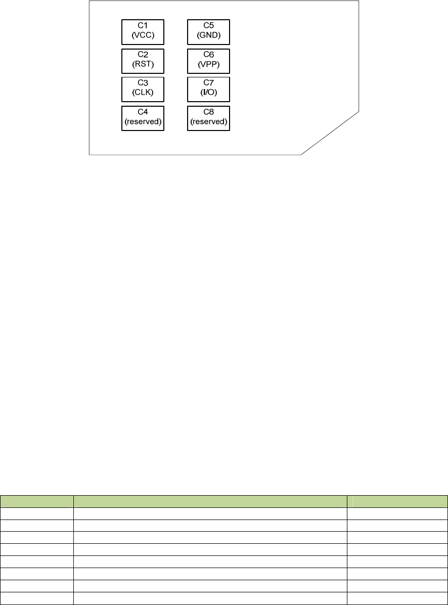
operation are defined in reference [32]. The figure below shows a “Plug in SIM” and its contact
locations.
GM.90026573 OEM INTEGRATION GUIDE – E362
Proprietary and Confidential
Novatel Wireless © 2011 Rev 1 29
Figure 5: SIM Contact Locations (viewed from contact side)
3.2.2 Typical Interface Design for the SIM
For the purposes of this document, the SIM interface is the interface between the SIM and the
laptop at the SIM connector. The SIM interface of the E362 modem provides power, clock, reset
and data to the SIM. The data is half duplex, bi-directional, meaning data is transferred in only
one direction at any time. The SIM operates in a command/response mode and it will only
transmit data in response to a received command. One exception to this is the Answer To Reset
(ATR) mode when the SIM transmits data in response to a reset.
The SIM is interrogated during the boot sequence of the E362 modem. First the SIM interface is
power sequenced for 1.8V operation. If 1.8 volt operation is unsuccessful then the SIM interface
is power sequenced for 3.0 volt operation. Just after boot up of the E362 modem, there will be a
large amount of data is transferred over the SIM interface. Later, the data transfer may be sparse,
only to ensure that the SIM is present at the interface. The operations indicated in this paragraph
are carried out automatically by the U362 modem. The systems integrator does not need to
introduce any circuit to distinguish a 1.8V SIM from a 3.0V SIM.
3.2.3 Description of Signals
The SIM interface consists of the signals listed in the Table below.
Table 12: SIM Interface Signals
Name Pin number of edge connector of E362 SIM card pin
VCC 8 C1
RST 14 C2
CLK 12 C3
Reserved not connected C4
GND 4, 9, 15, 18, 21, 26, 27, 29, 34, 35, 40, 50 C5
VPP 16 C6
IO 10 C7
Reserved not connected C8

GM.90026573 OEM INTEGRATION GUIDE – E362
Proprietary and Confidential
Novatel Wireless © 2011 Rev 1 30
GND
The GND signal is the ground for the SIM. All voltages are referenced to this.
VCC
The modem provides the power on the VCC rail. See the Table below for a summary of the 3GPP
electrical requirements.
Table 13: VCC Voltage Levels
Symbol Conditions Minimum Maximum Unit
VCCVCC 3V operation 2.7 3.3 V
VCCVCC 1.8V operation 1.62 1.98 V
RST
RST is driven by the E362 modem. A low signal indicates a reset condition.
See the Table below for a summary of the 3GPP electrical requirements.
Table 14: RST Electrical Requirements
Symbol Conditions Minimum Maximum Unit
VOH I
OHmax = + 200 µA 0.8 x VCC VCC V
VOL I
OLmax = 200 µA 0 0.2 x VCC V
tR tF 400 µs
CLK
The clock signal CLK is driven by the E362 modem. It is the system clock for the SIM. It may be
used by the SIM as its processor clock. The frequency of this signal may vary from 1 to 4 MHz.
The clock generally does not run continuously. The clock is stopped in between data transfers.
See the Table below for a summary of the 3GPP electrical requirements.
Table 15: CLK Electrical Requirements
Symbol Conditions Minimum Maximum Unit
VOH I
OHmax = + 20 µA 0.7 x VCC VCC V
VOL I
OLmax = 20 µA 0 0.2 x VCC V
tR tF 50 ns
I/O
I/O is the bi-directional data signal. The E362 modem may drive this signal low, or may pull it up
to VCC. The SIM may drive this signal low, or it may pull it up to VCC.
The I/O signal is much slower than the CLK signal. The default bit time is 372 clock periods. Each
data word is 10 bit times (a start bit, eight (8) data bits, and a parity bit). The data signals may be
transmitted under the Mark Space convention (high voltage is a binary 1, LSB sent first) or under
the reverse convention (low voltage is a binary 1, MSB sent first) depending on the ATR. See the
Table below for a summary of the 3GPP electrical requirements.
GM.90026573 OEM INTEGRATION GUIDE – E362
Proprietary and Confidential
Novatel Wireless © 2011 Rev 1 31
Table 16: I/O Electrical Requirements
Symbol Conditions Minimum Maximum Unit
VIH I
IHmax = ± 20 µA 0.7 x VCC VCC+0.3 V
VIL I
ILmax = + 1 mA 0.3 0.2 x VCC V
VOH I
OHmax = + 20 µA 0.7 x VCC VCC V
VOL VCC = 3V, IOLma
x
= 1mA 0 0.4 V
VOL VCC = 1.8V, IOLmax = 1mA 0 0.3 V
tR tF 1 µs
VPP
VPP is the programming voltage. It is not used and the SIM connector pin should not be
connected to the module edge connector.
Reserved
The reserved pins of the SIM connector should not be connected to the module edge connector.
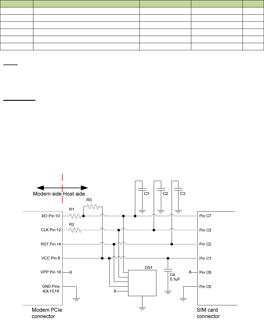
3.2.3. Typical Implementation of SIM card Interface
A typical implementation of the connection between the E362 module connector and the SIM
connector is shown in Figure 6. It is advised that ESD protection devices be assembled on the
host motherboard. Guidelines for the routing of the signals and the suggested values of the
passive components shown in the Figure are indicated below.
Figure 6: Typical Connection between SIM Connector and PCIe Edge Connector

GM.90026573 OEM INTEGRATION GUIDE – E362
Proprietary and Confidential
Novatel Wireless © 2011 Rev 1 32
Capacitors C1, C2, C3
C1, C2 and C3 are not to be populated. They exist if additional filtering is required. These
components should be placed close to the SIM connector.
Resistor R1, R2
R1 and R2 should be zero ohms. They exist if additional filtering is required.
Resistor R3
R3 is shown in the circuit as a place holder so that the I/O signal can be pulled up if required.
ESD protection Diode array DS1
DS1 should be a low capacitance ESD diode array (5 pF or less). It is important to minimize the
capacitance on the I/O line so data performance is not degraded (deterioration of rise and fall
times). DS1 should be placed close to the SIM connector. It is recommended that DS1 meets the
limits of IEC61000 4 2, level 4 (±15kV air discharge, ±8kV contact discharge).
Signal routing
The CLK line is a high speed digital signal and care must be taken to ensure it is isolated from
other signals. A guard trace should be used between the CLK trace and adjacent traces. A multi-
layer PCB with a ground plane should be used. The CLK trace should be routed in an inner layer.
CLK traces should be as short, and direct as possible, with no vias. All SIM card interface signals
should be routed carefully to avoid being corrupted by each other or external signals.
Capacitor on I/O signal trace
In order to function properly, there is a limit on the amount of capacitance per signal line. The
maximum capacitance added by the host (trace plus components) must not exceed 15pF per
signal.
Series resistance on the I/O signal trace
I/O traces may also have a pull up on the I/O signal, which would allow sinking of 1 mA into the
host motherboard when the I/O signal is driven low by the host motherboard. Series resistance
for the I/O signal must be kept very low as the voltage drop across it may cause the output
voltage at the connectors to be outside the specified limits.
3.2.4 Certification
Since the SIM card interface is unique to each Notebook PC, the SIM card and Notebook PC
together need to undergo several tests for obtaining certification. The electrical test cases are
specified in section 27.17.2 in Reference [29].
3.3 Guidelines for Integration of SMBus
In this Section, the SMBus interface of the E362 modem is described.
A 2 line SMBus is supported in hardware, but SMBus is not implemented in firmware other than
test provisioning. It may be customized based on customer requirements but would require
Novatel Wireless firmware effort.
GM.90026573 OEM INTEGRATION GUIDE – E362
Proprietary and Confidential
Novatel Wireless © 2011 Rev 1 33
The SMBus is a two wire interface through which various system components can communicate
with each other and the rest of the system. It is based on the principles of operation of the I2C
Bus. Please see References [3] and [2] for more details on the functional requirements for the
SMBus, and Reference [4] for the specification of the I2C bus.
In general, the SMBus is used for chip to chip communication on a motherboard. The E362
modem is a SMBus Master device, and not a Slave device. Typically, the SMBus protocol can be
used by the modem to report to a slave device about various states of the modem, for example
the arrival of an email.
SMBus on the modem does not support Clock Stretching and only supports a single master
configuration. It does not support slave configuration or multi-master mode.
The two wire interface of the SMBus consists of the SMB_CLK signal and the SMB_DAT signal.
These signals are connected to the baseband processor of the modem, and are available on pins
30 and 32 of the edge connector of the E362 module.
Both the SMB_CLK signal and the SMB_DAT signal are bi-directional lines The host SMBus
voltage is configurable with the only requirement that is ≥ 1.8V and that each line has a 2.2kΩ
resistor pull-up. When the bus is free, both lines are HIGH. The output stages of devices
connected to the bus must have an open drain or open collector to perform the wired AND
function. Accordingly, on the host side, a pull up resistor is to be present, connecting the Drain pin
to the voltage rail of the SMBus. Usually, the voltage rail on the host side is at 3.3V. It is expected
that the high power version of the SMBus will be implemented on the host platform (please see
Reference [3] for details on the high power version of the SMBus). For high power SMBus, the
maximum current through the pull up resistor is 4mA. Then, the value of the pull up resistor
should be calculated by taking into consideration the pull up resistors used within the modem on
the SMBus traces.
Following is the simplified description of the operation of the I2C bus.
• The Master (the modem) generates a START condition, signaling all Slave devices on the
bus to listen for data.
• The Master writes a 7 bit address, followed by a read/write bit to select the device as a
transmitter or receiver.
• The Slave device sends an acknowledgement bit over the Bus to the Master. The Master
must read this bit to determine whether or not the addressed Slave device is present on the
bus.
• Depending on the value of the read/write bit, any number of 8 bit messages can be
transmitted or received by the Master. These messages are specific to the I2C device used.
After 8 message bits are written to the bus, the transmitter will receive an acknowledge bit.
The transmission of messages and acknowledgements continues until the entire message is
transmitted.
• The message is terminated by the Master with a STOP condition. This frees the Bus for the
next master to begin communications.
• Data on the I2C bus can be transferred at rates of up to 100 kbps in the Standard mode,
• The number of interfaces connected to the bus is solely dependent on the bus capacitance
limit of 400 pF.

GM.90026573 OEM INTEGRATION GUIDE – E362
Proprietary and Confidential
Novatel Wireless © 2011 Rev 1 34
3.4 Guidelines Related to USB interface
The USB data lines D+ and D- carry differential signals at the maximum rate of 480 Mbps.
Accordingly, the design for these trances on the motherboard shall satisfy the requirements of
signal integrity and EMI compliance. Please refer to Reference [26] for a detailed description of
design considerations.
In general, the following guidelines may be followed.
• Do not route high speed traces close to the D+ and D- traces.
• Keep the trace length of these traces the same.
• USB host requires 90Ω differential characteristic impedance.

GM.90026573 OEM INTEGRATION GUIDE – E362
Proprietary and Confidential
Novatel Wireless © 2011 Rev 1 35
4. Getting Started with Development
4.1 General
The E362 modem can be integrated into all Windows driven host platforms, provided that the
drivers are properly installed on these platforms. When Novatel Wireless’ MobiLink 3™ is
installed on a Windows driven platform, all the drivers necessary for the communication between
the OS and the module is also installed automatically. The MobiLink 3™ is Novatel Wireless’
Windows Application Manager for PCI Express Mini Card modules and USB dongles. The
MobiLink 3™ Application Manager provides an easy interface to establish a data connection over
a wireless WAN, to change connection parameters, and to view system alerts such as an SMS
arrival or signal strength indicator. However, the drivers for Novatel Wireless’ modems can be
installed manually, independent of MobiLink 3™. Furthermore, after the drivers are installed,
Novatel Wireless’ NovaCore Client API functions may be made use of to develop a client side
connection manager running on the host platform.
After the installation of the E362 modem, the wireless network Carrier (the Service Provider) has
to perform activation of the modem before the modem can be used by a user to establish a
wireless data call successfully. Verizon Wireless performs the activation by a process called Over
the Air Service Provisioning (OTASP). Other Service Providers may use different processes for
activation of new modems.
The E362 requires a valid SIM before it can be used on the Service Provider’s wireless network.
Please contact the Technical Accounts Manager of Novatel Wireless if you encounter difficulties
in passing the OTASP phase of activation.
4.2 How to Set Up
For carrying out preliminary evaluation of the modem modules, a Modem Interface Board
(Novatel Wireless Part # 01017568) may be used by the integration personnel. Please See
Figure 7 for a picture of this Interface Board. This Interface Board can host the modem, and get
connected to the host platform over a USB cable. An AC adaptor is provided to provide the power
to the Interface Board. Setting up and establishing communication between the modem module
and the host platform involves the following steps:
• Hosting the modem on the Interface Board,
• Getting the modem enumerated as a USB device, and determining the host platform’s COM
Port being used by the modem.
• Setting up and using the HyperTerminal program to communicate with the modem.
Connections among the modem, the Interface Board and the host platform
Ensure that the +3V3SW Enable 2 pin header is shunted as indicated in Figure 7. This shunt
enables the status LEDs to light up when the Interface Board is provided with power as would be
described later in this Section.
Insert the modem module into the Interface Development Board by sliding the edge connector
end of the modem module into the 52 pin Molex connector. Push down the opposite end of the
modem module until the 2 black locking tabs snap in.
Connect the Interface Board to the host platform using the USB cable you received along with
the Interface Board.
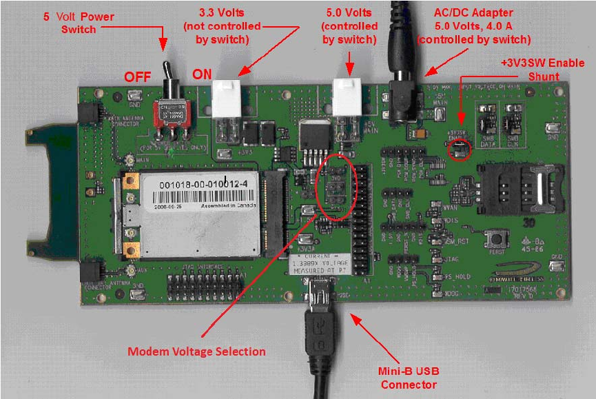
GM.90026573 OEM INTEGRATION GUIDE – E362
Proprietary and Confidential
Novatel Wireless © 2011 Rev 1 36
When ready to power up the modem, plug the AC wall adaptor. Ensure that you use the AC wall
adaptor provided with the Interface Board. This will supply 5V to the Interface Board.
Figure 7: Modem Interface Board and Cables
When power is made available to the Interface Board, switch the red toggle switch to the ON
position. (Note: the ON position of the switch is when it is pushed toward the SIM card connector
on the Interface Board; the OFF position is when it is pushed away from the SIM card connector.
These positions are illustrated in Figure 7.).
If desired, the Interface Board can be powered by a bench top DC power supply through the
appropriate white, 4 pin Molex power connector (see Figure 7). J11 is for external 5V input, and
J12 is for external 3.3V input. The current rating of the external DC supply should be at least
4.0A.
The toggle switch provides ON/OFF control for both 5V input sources, but NOT the 3.3V source.
The Interface Board is powered on as soon as the 3.3V is applied.
MODEM VOLTAGE SELECTION: Refer to Figure 7 to locate the 2 pin headers that select 3V0,
3V3, or 3V6 DC power to the modem. The E362 modem utilizes nominal 3.3V supply power
specified in the PCIe Mini card standard, so ensure that the 3V3 2 pin header is shunted with a
jumper. This is the default shunt position. Note that if no jumper is installed the supply power to
the modem defaults to 3V0 and may result in lower than expected transmitter power. Also note
that these 2 pin headers will only control the voltage to the modem from the external 5.0V
sources (AC/DC adapter and J11), but NOT from the external 3V3 source via J12.
After the modem is powered up and enumerated by the host platform, the host platform generally
generates an audible indication.
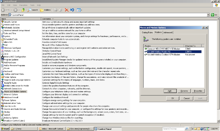
GM.90026573 OEM INTEGRATION GUIDE – E362
Proprietary and Confidential
Novatel Wireless © 2011 Rev 1 37
Determining the host platform’s Active Primary COM Port
To verify that the host platform has recognized the modem, and to examine which COM Port is
used by the modem, please use the following command links;
• Start Æ Control Panel Æ Phone and Modem Options, and then click on the Modems
tab within the Phone and Modem Options window.
• After the command sequence indicated above, a Window similar to the one shown in
Figure 8 below will be displayed.
Figure 8: Phone and Modems Options Window
• Look on the Window for the listing of the Novatel Wireless Modem (E362). If such an item
is present in the listing, you will see to the right of this item the COM port the device is
attached to. Take note of this COM Port Number. If you do not see any COM port No. for this
item and you only see “Not Present”, it is an indication that the modem is not being
recognized and is not attached to a COM Port of the host platform. In this case, make sure
the USB cable and the power cable are properly connected at both ends.
Determining the host platform’s Active Secondary or Status COM Port
To verify what the numbers of the secondary port and the status port are, use the following
command links;
• Start Æ Control Panel Æ System.
• Double click on the System icon and then click on the Hardware Tab within the System
Properties window. Now click on the Device Manager tab. In the Device Manager window,
click on the “+” sign beside Modems to expand this item. You should now see the Novatel
Wireless Modem, or something similar to the list as shown in Figure 9. Now click on the “+”
sign beside Ports (COM & LPT) to expand this item. You should now see the Novatel
Wireless Status Port (COMXX) listed here. The XX is the COM Port number.
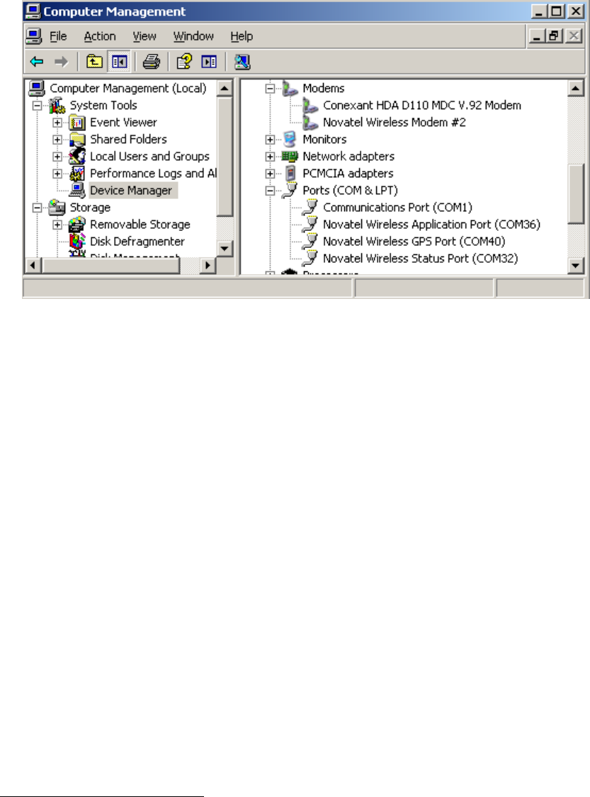
GM.90026573 OEM INTEGRATION GUIDE – E362
Proprietary and Confidential
Novatel Wireless © 2011 Rev 1 38
• Refer to Figure 9 below, which also shows the Application Port and GPS Port. The
Novatel Wireless Application Port displayed here will be used for NovaCore API to
communicate with the modem. The Novatel Wireless GPS Port will be used to get NMEA
data for GPS/LBS supported device.
Figure 9: Device Manager Window Showing the Computer’s Active COM Ports
Setting up HyperTerminal to communicate with the modem
After ensuring that the ports are available as described above, tests may be carried out over
these ports. For conducting these tests, ensure the HyperTerminal application of the Windows
OS1. Before proceeding for these tests, ensure that the modem is still powered on and is
connected to the host platform over the USB cable, and it has been enumerated by the host.
Open up a HyperTerminal session by navigating to;
• Start Æ All Programs Æ Accessories Æ Communications Æ HyperTerminal.
• Type in a Connection Description title defined by you, typically the COM Port number that
was identified earlier. Click ‘OK’. Then you will see a display similar to the shown Figure 10.
1 Note that Windows Vista and Windows 7 may not come with HyperTerminal. The user may
need to install it separately.
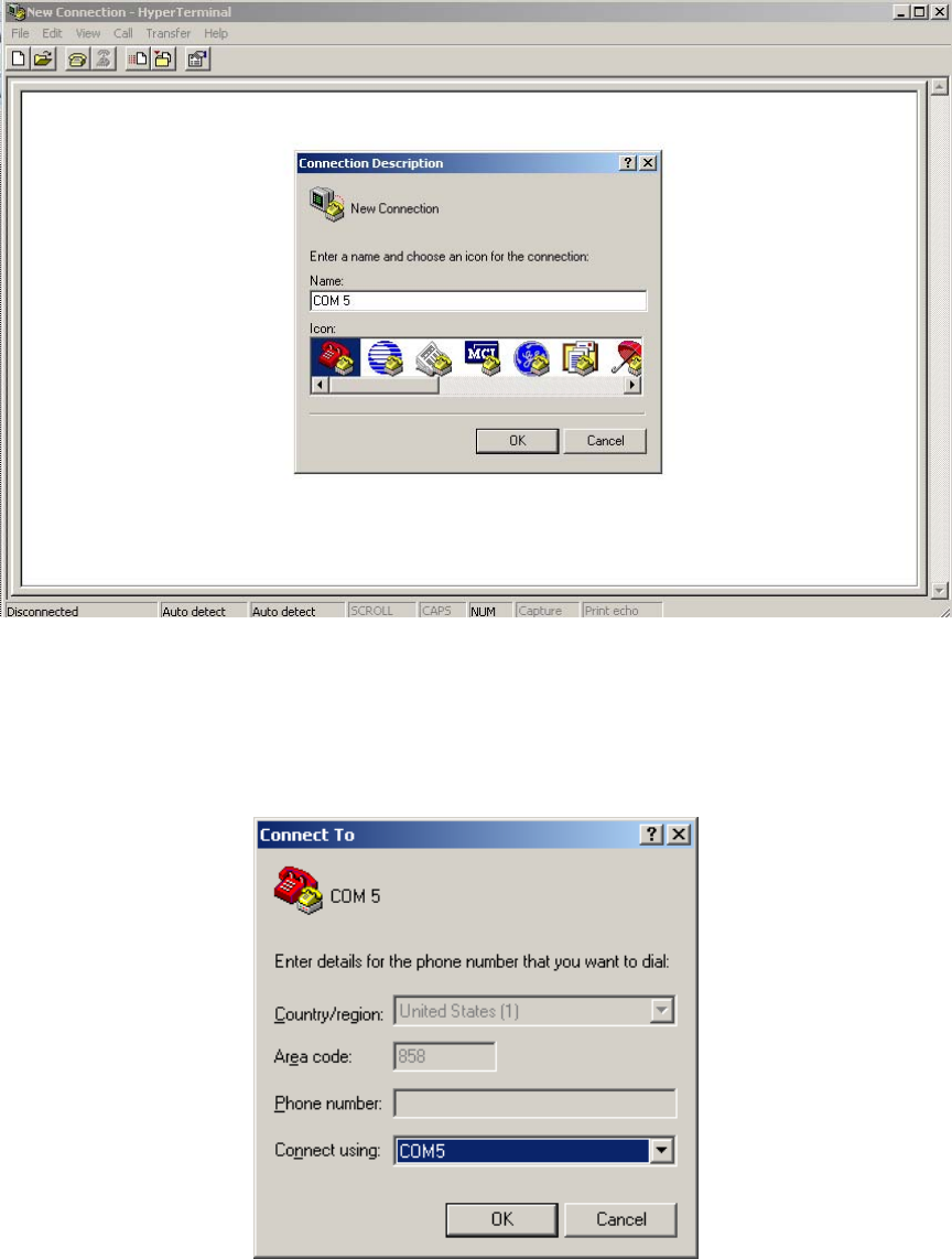
GM.90026573 OEM INTEGRATION GUIDE – E362
Proprietary and Confidential
Novatel Wireless © 2011 Rev 1 39
Figure 10: HyperTerminal Connection Description Window
• In the “Connect Using” pull down menu, select the proper COM port (Primary COM port
number) that the host is using to communicate with the modem, then click ‘OK’. You will see
a display similar to the one shown in Figure 11 below.
Figure 11: HyperTerminal COM Port Selection Window
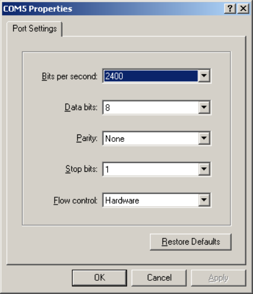
GM.90026573 OEM INTEGRATION GUIDE – E362
Proprietary and Confidential
Novatel Wireless © 2011 Rev 1 40
• When the ‘COMXX Properties’ window opens up, click the OK button as there is no need
to select or modify any of these settings. Typically, the display will be as indicated in Figure
12 below.
Figure 12: HyperTerminal Properties Window
Now the modem should be automatically connected, as will be indicated in the bottom left corner
of the HyperTerminal window. To further ensure that the connection to the modem is successful,
type “ATI” and press ENTER. In response, the modem manufacturer, model number, FW revision
and IMEI information will then be returned as is shown in Figure 13 below.
If no information is returned in the HyperTerminal window after typing ATI, then click on the
Disconnect tab at the top of the HyperTerminal window (or click on Call\Disconnect). Reconnect
by clicking on the Connect tab at the top of the HyperTerminal window (or click on Call\Connect).
Now type the command ATE to enable the “Echo” function of the modem. When the Echo
function is active, it will allow the characters typed on the key board to be displayed on the
HyperTerminal window. After typing the ATE command, type the command ATI. As a response to
this command, the modem will display information on the HyperTerminal window, similar to the
display indicated in Figure 13.
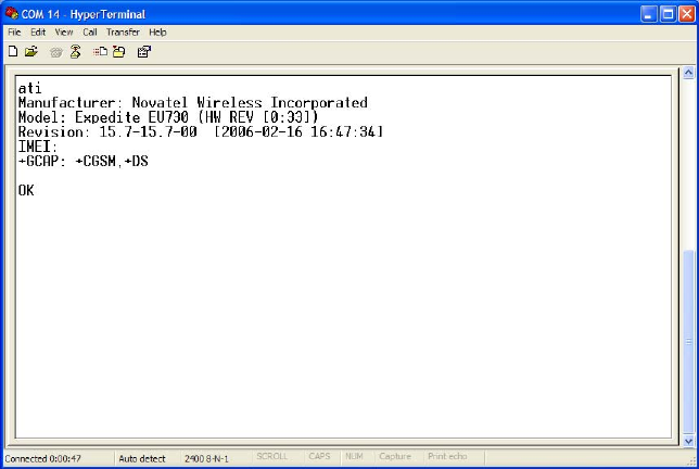
GM.90026573 OEM INTEGRATION GUIDE – E362
Proprietary and Confidential
Novatel Wireless © 2011 Rev 1 41
Figure 13: HyperTerminal Communication Window
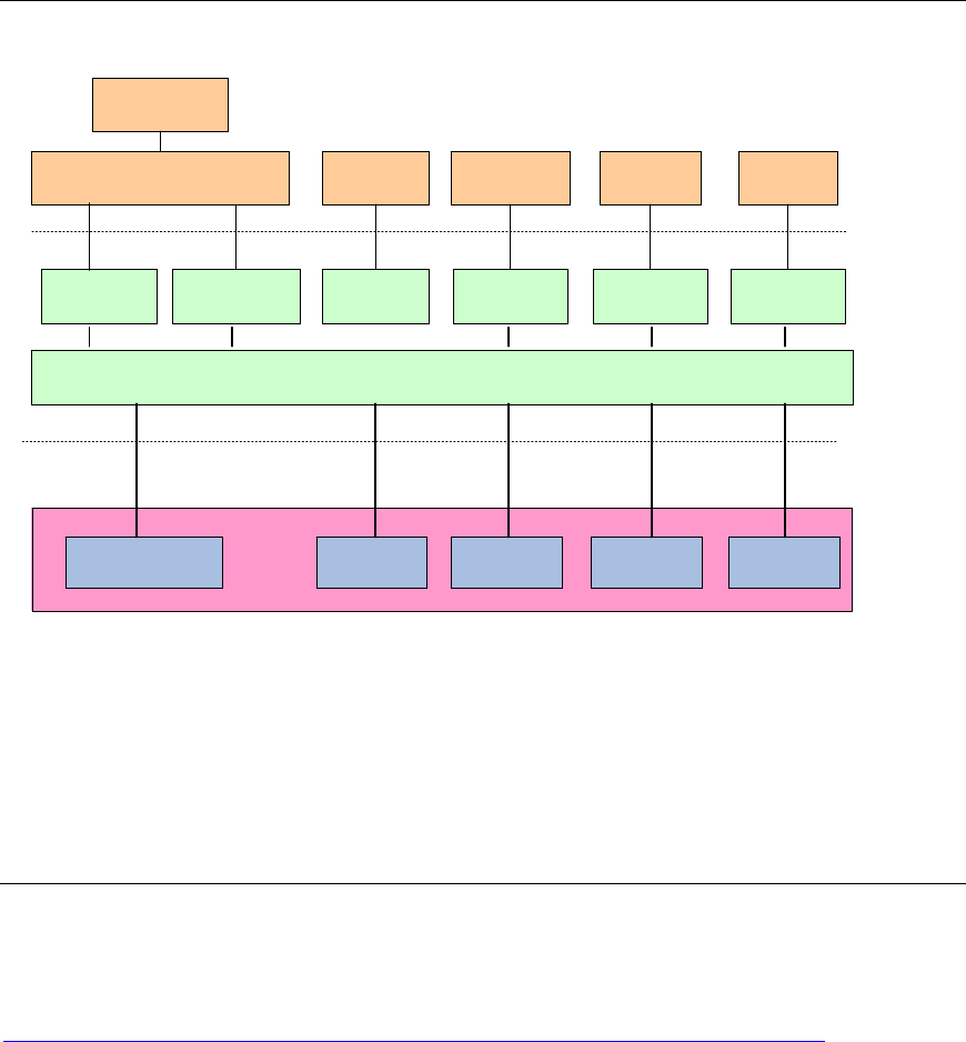
GM.90026573 OEM INTEGRATION GUIDE – E362
Proprietary and Confidential
Novatel Wireless © 2011 Rev 1 42
5. Host Software
As indicated in Section 2.2.4, the E362 modem is a USB 2.0 High Speed end point device.
Essentially, this modem provides wireless Internet connectivity to the host. In this section, a brief
description is given on the host side Drivers, Tools and Application Programs to make the
developer familiar with them. Some of the Tools and Application Programs are distributed either
through CD or may be downloaded over the Internet.
5.1 Drivers
Figure 14: Block Diagram of Driver Components on Host
Various modules on the host side Driver are indicated in Figure 14. Please note that the ports
indicated at the Interface for E362 (GPS port, Diag/App port, Ststus port, etc.) are Virtual COM
ports of the USB interface, and these ports are implemented on the host platform using the
Communication Device Class (CDC) drivers.
5.2 NovaCore SDK
A software framework called Novacore has been developed by Novatel Wireless to be used by
systems integrators and application developers. This framework will be called the NovaCore SDK
for the rest of this document. The NovaCore SDK can be downloaded from the following site:
http://www.nvtl.com/index.php?option=com_content&view=article&id=8&Itemid=254
The Integrators and Developers are required to register themselves at this site before they would
be enabled to download the information related to NovaCore. The link indicated above can be
used to arrive at a site wherein the latest SDK drivers, APIs and software applications could be
Network Interface
RMNet/ CDC ECM Modem
/
A
T
Port Status Port Diag
/
A
pp
Port GPS Port
Modem
Drive
r
Serial Port
Drive
r
Serial Port
Drive
r
Serial Port
Drive
r
RMNet NDIS
6. 2 ( Win 7
RMNet NDIS
5. 1 ( XP, Vista )
Win 7 WWAN
SDK
NDIS Mini Port Dialup
Networking
Interface fo
r
E362
Driver Stack
OS Components
NVTL USB Composite Drive
r
Status Port
A
pp
/
Diag
NMEA
Port
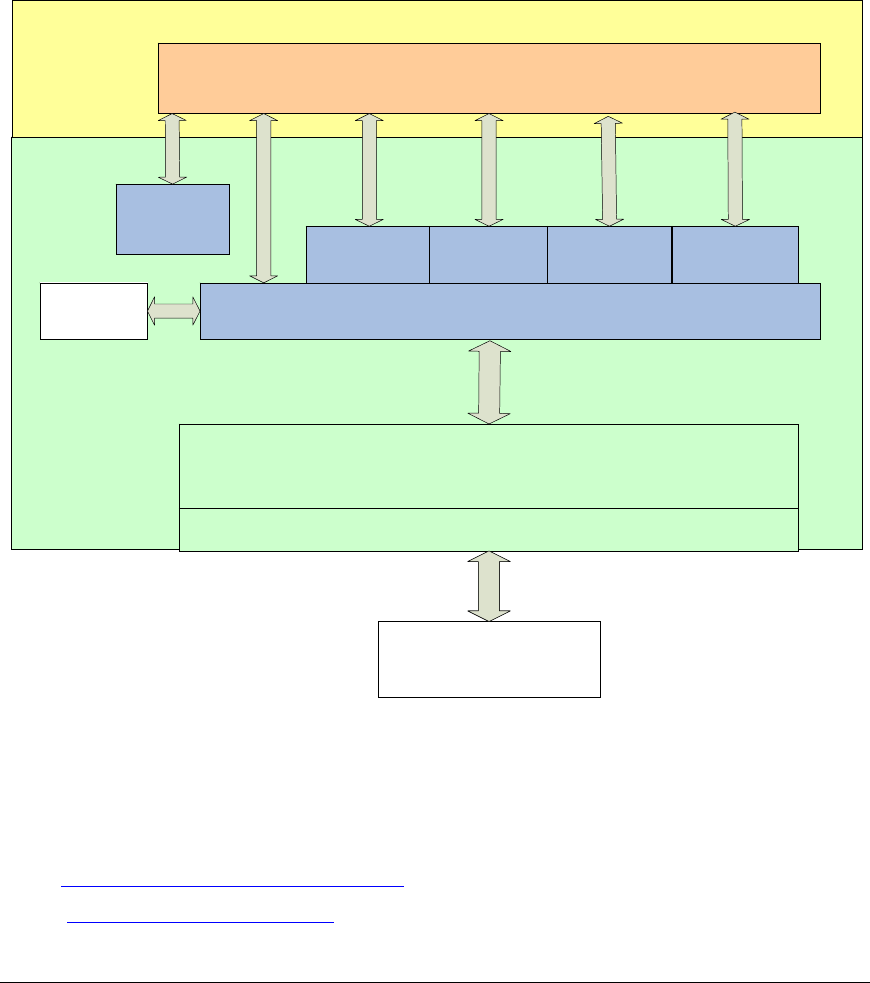
GM.90026573 OEM INTEGRATION GUIDE – E362
Proprietary and Confidential
Novatel Wireless © 2011 Rev 1 43
found. Information obtained from this link also helps one to leverage the capabilities of various
hardware solutions of Novatel Wireless. This link also offers a venue for exchanging tips among
developers of fellow industries, and a forum to discuss about the latest news on development.
The Figure below illustrates how the NovaCore framework helps in the integration of software
applications.
Figure 15: Integration of Software Application Using NovaCore SDK
Technical Support Contacts
For technical support, following is the contact address:
URL: http://www.nvtl.com/support/index.html
Email: support@novatelwireless.com
5.3 MobiLink 3™ Connection Manager
The Novatel Wireless’ MobiLink 3™ Communications Software Suite is a family of wireless
connectivity applications for mobile devices to connect to the Internet using wireless wide area
Networks (WWAN), WiFi access or Ethernet access. Using MobiLink 3™, an application can
quickly and easily access the Internet and corporate networks anytime, anywhere, and make use
of associated software applications such as email.
Core - NvtlSdk.dll
Server (Windows Service - NvtlSrvr.exe)
Core - NvtlSdk.dll
OS Serial Port
(diagnostic port, fall back to
status port)
Connection
NvtlConn.dll
SMS
Encoder
NvtlEnc.dll FileManager
NvtlFile.dll
Diagnostics
NvtlDiag.dll
GPS
NvtlGps.dll
User Application Modules
Application
Gobi SDK
NovaCore SDK
Core - NvtlSdk.dll
Server (Windows Service - NvtlSrvr.exe)
Core - NvtlSdk.dll
OS Serial Port
(diagnostic port, fall back to
status port)
Connection
NvtlConn.dll
SMS
Encoder
NvtlEnc.dll FileManager
NvtlFile.dll
Diagnostics
NvtlDiag.dll
GPS
NvtlGps.dll
User Application Modules
Application
Gobi SDK
NovaCore SDK
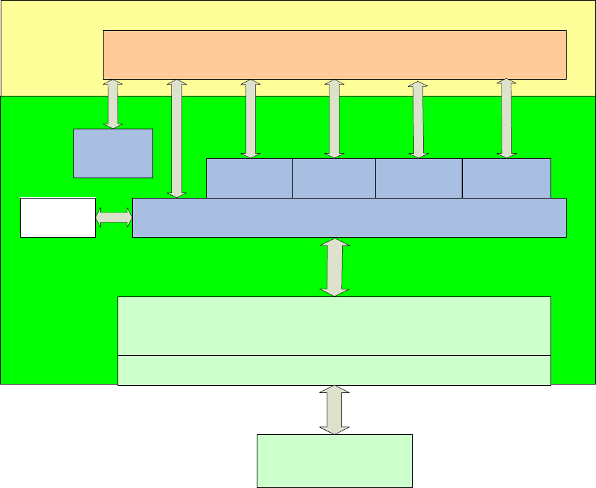
GM.90026573 OEM INTEGRATION GUIDE – E362
Proprietary and Confidential
Novatel Wireless © 2011 Rev 1 44
MobiLink 3™ is optimally engineered to work with all of Novatel Wireless' modems for best in
class 3G and 4G wireless broadband access solutions, and may be used to install and configure
the E362 modem. E362 customers also have the option to use their own preferred Connection
Manager instead of the MobiLink 3™ Connection Manager.
Figure 16: MobiLink™ in the Context of NovaCore
The MobiLink3™ Communications Software Suite of applications contains a Messaging Client
that manages a 2 way SMS operations, an Address Book Client that manages contacts and
phone numbers, a Connection Manager that manages the connectivity, and a customization utility
to manage, generate install customization settings. Figure 16 illustrates the MobiLink in the
context of NovaCore.
The important features offered by Mobilink™ are indicated below:
• AT Command Set Support per IS 707,
• Fully compatible and interoperable with current Microsoft™ OS platforms: 32/64 bit Windows
XP, 32/64 bit Windows Vista, 32/64 bit Windows 7
• Integrated drivers for Windows OS, configurable as either a modem or network card
• PCI Express Mini card compatible hardware interface
• Compatibility with all major brands of PC platforms
Core - NvtlSdk.dll
Server (Windows Service - NvtlSrvr.exe)
Core - NvtlSdk.dll
OS Serial Port
(diagnostic port, fall back to
status port)
Connection
NvtlConn.dll
SMS
Encoder
NvtlEnc.dll FileManager
NvtlFile.dll
Diagnostics
NvtlDiag.dll
GPS
NvtlGps.dll
User Application Modules
Application
Gobi SDK
NovaCore SDK
Core - NvtlSdk.dll
Server (Windows Service - NvtlSrvr.exe)
Core - NvtlSdk.dll
OS Serial Port
(diagnostic port, fall back to
status port)
Connection
NvtlConn.dll
SMS
Encoder
NvtlEnc.dll FileManager
NvtlFile.dll
Diagnostics
NvtlDiag.dll
GPS
NvtlGps.dll
User Application Modules
Application
Gobi SDK
NovaCore SDK

GM.90026573 OEM INTEGRATION GUIDE – E362
Proprietary and Confidential
Novatel Wireless © 2011 Rev 1 45
• Sleep mode capabilities (low power mode)
• Uses common base technology shared with OEM Module
• IS 683A compliant Over The Air activation and parameter update capabilities
• On line help, getting started guide, documentation
• All software applications necessary to communicate with the PCI Express Mini Card will
operate with above supported systems.
• All software supports 640x480, 640x240, and 800x600 color and monochrome displays
• MobiLink 3™ allows the user to configure the modem easily
• MobiLink 3™ provides diagnostic capability
• MobiLink 3™ provides a Help menu that is Context Sensitive
If required, contact Novatel Wireless technical support for the MobiLink 3™ User Guide, and
supported AT commands.
5.4 Novaspeed™
Novatel Wireless’ Novaspeed™ is an Application Software that can be run within the modem.
The Application Software helps to obtain higher throughput rates over 3G wireless WAN
connections. Perhaps, such a performance enhancement is not required for 4G wireless WAN
connections. If a customer needs such performance enhancements over 3G wireless WAN
connections, he may contact Novatel Wireless for its implementation.

GM.90026573 OEM INTEGRATION GUIDE – E362
Proprietary and Confidential
Novatel Wireless © 2011 Rev 1 46
Appendix A - Compliance with Regulatory Standards
A.1 FCC Requirements Related to Radio Interference
The modem described in this document have been tested and found to comply with the limits for
a Class B digital device, pursuant to Part 15 of the FCC Rules and Industry Canada ICES 003.
These limits are designed to provide reasonable protection against harmful interference in a
residential installation. A modem radiates radio frequency energy and, if not installed and used in
accordance with the instructions, may cause harmful interference to radio communications.
However, there is no guarantee that interference will not occur in a particular installation. If this
equipment does cause harmful interference to radio or television reception, which can be
determined by turning the equipment off and on, the user is encouraged to try to correct the
interference by one or more of the following measures:
• Reorient or relocate the receiving antenna.
• Increase the separation between the equipment and receiver.
• Connect the equipment into an outlet on a circuit different from that which the receiver is
connected.
• Contact your service provider for help.
Warning: Changes or modifications made to the modem not expressly approved by Novatel
Wireless may void the FCC authorization to operate this equipment.
Operation is subject to the following two conditions:
(1) This device may not cause harmful interference, and
(2) This device must accept any interference received, including interference that may
cause undesired operation.
A.2 FCC Requirements Related to Exposure to Radio Frequencies
In general, for the United States Market, the embedded wireless modules are treated as “mobile
devices” as per FCC CFR47 paragraph 2.1091. A mobile device is defined as “a transmitting
device designed to be used in locations other than fixed locations and to generally be used in
such a way that a separation distance of at least 20 cm is normally maintained between the
transmitter radiating structure(s) and the body of the user or nearby persons.”
Please note that certain Europe specific requirements and certifications listed below do not apply
to modems which are intended to be used only in the North American market.
A.3 Requirements of CE
The modems for the European Market will be tested for conformance with the regulatory
requirements of the European Union and, accordingly, they have attained CE Marking. The CE
Mark is a conformity marking consisting of the letters "CE". The CE Mark applies to products
regulated by certain European health, safety and environmental protection legislation. The CE
Mark is obligatory for products it applies to: the manufacturer affixes the marking in order to be
allowed to sell his product in the European market.

GM.90026573 OEM INTEGRATION GUIDE – E362
Proprietary and Confidential
Novatel Wireless © 2011 Rev 1 47
A.4 Requirements of R&TTE
Compliance with this directive is mandatory for European operation and the directive applies to
products using the radio frequency spectrum and all equipment attached to public
telecommunications networks.
The modem described in this document conforms to the essential requirements of the Radio
Communications and Telecommunications Terminal Equipment Directive (R&TTE) 1999/5/EC
with respect to the following articles:
• 3.1a Safety
• 3.1b EMC
• 3.2 Spectrum
A notified body will determine whether the modem has properly demonstrated that the
requirements of the directive have been met and has issued a favorable certificate of expert
opinion. As such the device will bear the notified body number 0682 after the CE Mark.
A.5 Requirements of PCS Type Certification Review Board (PTCRB)
PTCRB Certification is mandated and the modem is technically evaluated to meet the minimum
requirements for registration on the PTCRB Operators’ networks. The purpose of the PTCRB is to
provide the framework within which GSM Mobile Equipment (ME) Type Certification can take
place for members of the PTCRB. The PTCRB process is recommended for all Manufacturers
who wish to have their products operating within the areas served by the PTCRB Operators. This
includes but is not limited to determination of the test specifications and methods to implement
the Type Certification process for GSM Mobile Equipment.
PTCRB type certification will be based on GSM and OMA (Open Mobile Alliance) Specifications
with modifications per North American Standards and additional requirements from FCC rules,
and any other government agency that may have jurisdiction and (or) competence in the matter.
Additions to the PTCRB Specifications will be developed by the GSM operators. The additions
will be limited to MS related features. The PTCRB document NAPRD 03 (Permanent Reference
Document) will be modified to include references to the above specifications once they are written
and accepted by majority of the review board.
To learn more about device certifications, please visit the PTCRB Website. You must sign up as a
member to gain access.
A.6 Requirements of Global Certification Forum (GCF),
The Global Certification Forum (GCF) is an independent organization with a wide ranging
membership of operators, equipment manufacturers and other interested parties. The actions of
the Forum are actively supported by key staff from the Association Technical Projects operation
and by the Association Executive Management Committee.
GCF is recommended but not mandatory for attachment to the European Network. It is a
partnership between Network Operators and Terminal Manufacturers and allows independent
interoperability validation of the 2G and 3G mobile wireless terminal. GCF is typically required for
formal carrier technical acceptance of the mobile, wireless terminal. From the 26th of December,
2010 onwards, the GCF Certification process can be applied to certain LTE devices also.

GM.90026573 OEM INTEGRATION GUIDE – E362
Proprietary and Confidential
Novatel Wireless © 2011 Rev 1 48
Membership of GCF is entirely voluntary. Full GCF membership is open to mobile terminal
manufacturers and network operators. Other interested members of the mobile wireless
community, including test laboratories and test equipment manufacturers, may participate in GCF
as observers.
The current membership includes almost 150 network operators worldwide, more than 35 leading
terminal manufacturers and over 50 test equipment manufactures. Members decide upon the
organization and administration of the forum at regular Steering Group meetings. Technical
issues associated with testing new terminals and features are reviewed at regular Agreement
Group meetings by manufacturers, test laboratories and other observers.
To learn more about device certifications, please visit the GCF Website. The website identifies
manufacturers, Terminal names and the date on which the Terminal was certified. You must sign
up as a member to gain full access.
A.7 Conformance with the Windows Certified Platforms
The NovaCore Software Developers Kit API will interface with your top level applications and
provide the abstraction of the modem specific interfaces to the upper applications. Please refer to
the NovaCore API Interface Appendix for details.
Please refer to the NovaCore SDK chapter for details on developing applications and
communicating with the modem on Windows platforms.
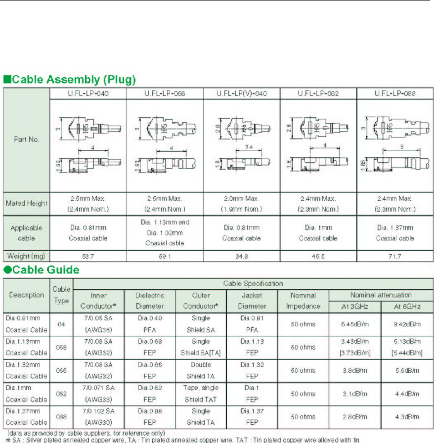
GM.90026573 OEM INTEGRATION GUIDE – E362
Proprietary and Confidential
Novatel Wireless © 2011 Rev 1 49
Appendix B - Specification of Parts
B.1 RF Connector
Hirose U.FL series, with U.FL R SMT receptacle mating to the following connectors illustrated.
Note that .this connector is designed for a limited number of insertions. For an embedded
application this is expected to be acceptable.
Figure 17: RF Connector
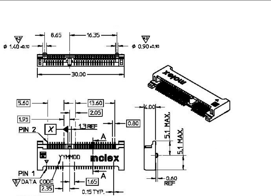
GM.90026573 OEM INTEGRATION GUIDE – E362
Proprietary and Confidential
Novatel Wireless © 2011 Rev 1 50
B.2 Mini Card Connector
The Molex 67910 series, mates with the mini PCI Express Card. Use with Latch 48099 0003.
Figure 18: Mini Card Connector
GM.90026573 OEM INTEGRATION GUIDE – E362
Proprietary and Confidential
Novatel Wireless © 2011 Rev 1 51
Appendix C - Glossary
Abbreviations given in 3GPP TR 21.905 [15] and the following apply.
AT Commands
AT commands are a language type that enables PC communications software to give the modem
directions. The term AT comes from the command terminology which always begins with
attention, or AT.
Carrier
See Service Provider
Circuit Switched Data
A wireless network connection established, using a single circuit that extends from you, directly
through the network to your call’s destination. Opposite of packet switched.
CLI
Command Line Interface.
Code Division Multiple Access (CDMA)
Code Division Multiple Access is a spread spectrum wireless access technology that allows
multiple users to share the same physical RF channel (1.25MHz for single carrier direct spread
1X) by use of orthogonal code spreading.
Connection Profile
See Network Connection Profiles
dBm
The power ratio in decibels (dB) of the power referenced to one milliwatt (mW).
Default Network Connection Profile
The default network connection profile is the connection profile, chosen by you that the Modem
Manager will use to connect to the network. The default network connection profile can be
thought of as the active network connection profile.
Edge Technologies
Edge (Enhanced Data for Global Evolution) is an enhanced version of GPRS providing three to
four times more capacity and data throughput. Average speeds range from 100 to 130 kbps with
theoretical peak data rates of 473 kbps. Average rates are fast enough to support a wide range of
advanced data services such as streaming audio and video, fast Internet access and large file
downloads, EDGE can also support a greater range of enterprise applications, and more
multimedia applications including push to talk services.
Firmware
Firmware is a program or set of programs that have been set permanently into a computer chip.
The programs themselves usually are low level programs that directly manipulate or interact with
the hardware. An example of firmware is your desktop computer’s BIOS.
General Packet Radio Service (GPRS)
GRPS is a packet based, always on data connection standard.
High Speed Downlink Packet Access (HSDPA)
HSDPA is a packet based data service that improves upon UMTS by increasing speeds to 500
800 kbps with peak data rates of up to 10 Mbps (five times faster than UMTS and other 3G
technologies) in a 5 MHz channel. In addition, HSDPA significantly improves packet data
throughput capacity, thereby increasing the number of users that can be supported at higher data
rates on a single radio carrier.
GM.90026573 OEM INTEGRATION GUIDE – E362
Proprietary and Confidential
Novatel Wireless © 2011 Rev 1 52
IMEI
IMEI stands for International Mobile Station Equipment Identity.
Mega Hertz (MHz)
One million hertz. Hertz is another word for cycles in a radio frequency.
Mobile Station (MS)
The device being used to receive/transmit data and/or voice.
Mobile Terminal (MT)
NDIS Network Driver Interface Specification
This is an API developed for Microsoft Windows OS to be used with Network Interface Cards.
Network Connection Profiles
A network connection profile is a group of connection settings that define a specific network
connection to the Modem Manager. This includes such settings as network ID, network
password, APN, DNS addresses and so on.
Original Equipment Manufacturer (OEM)
The original manufacturer of a pieces of equipment, typically complete boards, duplexers or
enclosures etc.
Over The Air (OTA)
Packet
A short block of data transmitted across a network.
Packet Data Network (PDN)
Network that carries user data in packets. ex. Internet and X.25
Radio Link Protocol (RLP)
Service Provider
A company that provides network connections to the Internet.
Short Message Service (SMS)
Short messages either in binary (160 characters) or text messages (140 bytes) format.
Terminal Equipment (TE)
Um
Mobile to Base Station air interface link.
Universal Product Support Tool (UPST)
The Universal Product Support Tool (UPST) consists of the UPST Framework and UPST device
DLLs. The UPST Framework is a Windows 32 application (UPST.exe) that uses UPST device
Dynamic Link Libraries (DLLs) to provide basic device provisioning functions such as Refurbish,
Software upgrades, Preferred Roaming List (PRL) upgrades, and Phone Settings programming.
User Datagram Protocol (UDP)
Another protocol on top of IP.
Wireless IP Network
A wireless network (e.g. CDMA) that uses Internet Protocol (IP)