Novatel 01017829 GPS Receiver with Bluetooth User Manual Technical Writer
Novatel Inc GPS Receiver with Bluetooth Technical Writer
Novatel >
Contents
- 1. User Manual part 1
- 2. User Manual part 2
User Manual part 1
OM-20000093 Rev 5B
OEMV Family
Installation and Operation
User Manual

2 OEMV Family Installation and Operation User Manual Rev 5B
Proprietary Notice
OEMV Family Installation and Operation User Manual
Publication Number: OM-20000093
Revision Level: 5B
Revision Date: 2007/03/23
Proprietary Notice
Information in this document is subject to change without notice and does not represent a commitment
on the part of NovAtel Inc. The software described in this document is furnished under a licence
agreement or non-disclosure agreement. The software may be used or copied only in accordance with
the terms of the agreement. It is against the law to copy the software on any medium except as
specifically allowed in the license or non-disclosure agreement.
No part of this manual may be reproduced or transmitted in any form or by any means, electronic or
mechanical, including photocopying and recording, for any purpose without the express written
permission of a duly authorized representative of NovAtel Inc.
The information contained within this manual is believed to be true and correct at the time of
publication.
NovAtel, ProPak, RT-2 and RT-20 are registered trademarks of NovAtel Inc.
PAC, AdVance RTK, FlexPak-V1, FlexPak-V1G, FlexPak-V2, DL-V3 and SMART-V1 are
trademarks of NovAtel Inc.
All other brand names are trademarks of their respective holders.
Manufactured and protected under U.S. Patent:
© Copyright 2006-2007 NovAtel Inc. All rights reserved. Unpublished rights
reserved under International copyright laws. Printed in Canada on recycled paper.
Recyclable.
PAC Correlator
#6,243,409 B1
#5,414,729
Narrow Correlator
#5,101,416
#5,390,207
#5,495,499
#5,809,064
GLONASS
#6,608,998 B1
GALILEO
#6,184,822 B1
Dual Frequency GPS
#5,736,961
Position for Velocity Kalman Filter
#6,664,923 B1
Anti-Jamming Technology
#5,734,674
RTK Positioning
#6,728,637 B2
#6,664,923 B1

OEMV Family Installation and Operation User Manual Rev 5B 3
Table of Contents
Table of Contents
Table of Contents 3
Notice 10
Software License 15
Warranty 17
Customer Service 18
Foreword 19
1 Introduction 20
1.1 Overview of the OEMV Family..............................................................................20
1.1.1 Common Features.......................................................................................20
1.2 OEMV Cards.........................................................................................................21
1.2.1 OEMV-1 Card..............................................................................................21
1.2.2 OEMV-1G Card ...........................................................................................22
1.2.3 OEMV-2 Card..............................................................................................22
1.2.4 OEMV-3 Card..............................................................................................23
1.3 OEMV-Based Enclosures .....................................................................................25
1.3.1 ProPak-V3 and DL-V3.................................................................................26
1.3.2 FlexPak........................................................................................................ 28
1.3.3 SMART-V1 .................................................................................................. 29
2 Receiver System Overview 30
2.1 OEMV Card...........................................................................................................31
2.1.1 Radio Frequency (RF) Section....................................................................31
2.1.2 Digital Electronics Section...........................................................................31
2.2 Enclosure and Wiring Harness .............................................................................31
2.3 GNSS Antenna .....................................................................................................31
2.3.1 Optional LNA Power Supply........................................................................32
2.4 Principal Power Supply.........................................................................................32
2.5 Data Communications Equipment ........................................................................32
3 Installation and Set Up 33
3.1 Additional Equipment Required ............................................................................33
3.1.1 Selecting a GNSS Antenna ......................................................................... 33
3.1.2 Choosing a Coaxial Cable........................................................................... 34
3.1.3 Power Supply Requirements....................................................................... 34
3.2 Installation Overview............................................................................................. 36
3.2.1 Installing an OEMV Card in a Wiring Harness and Enclosure.....................36
3.2.2 Mounting Bracket (DL-V3 and ProPak-V3 Only) .........................................39
3.2.3 Mounting the GNSS Antenna ......................................................................39
3.2.4 Connecting the Antenna to the Receiver..................................................... 40
3.2.5 Applying Power to the Receiver ..................................................................40
3.2.6 Connecting Data Communications Equipment............................................41
3.3 Additional Features and Information..................................................................... 44
3.3.1 Strobes ........................................................................................................44

4 OEMV Family Installation and Operation User Manual Rev 5B
Table of Contents
3.3.2 Universal Serial Bus (USB)......................................................................... 45
3.3.3 CAN Bus ..................................................................................................... 46
3.3.4 Status Indicators ......................................................................................... 47
3.3.5 DL-V3 Status Indicators.............................................................................. 48
3.3.6 External Oscillator (OEMV-2, OEMV-3, DL-V3 and ProPak-V3 only)......... 51
3.3.7 Antenna LNA Power ................................................................................... 51
3.3.8 DL-V3 Removable Compact Flash Memory Card....................................... 52
4 Operation 56
4.1 Communications with the Receiver ...................................................................... 57
4.1.1 Serial Port Default Settings......................................................................... 57
4.1.2 Communicating Using a Remote Terminal ................................................. 57
4.1.3 Communicating Using a Personal Computer.............................................. 57
4.2 Getting Started ..................................................................................................... 58
4.2.1 Starting the Receiver .................................................................................. 58
4.2.2 Communicating with the Receiver Using CDU ........................................... 58
4.3 Transmitting and Receiving Corrections............................................................... 60
4.3.1 Base Station Configuration ......................................................................... 61
4.3.2 Rover Station Configuration........................................................................ 62
4.3.3 Configuration Notes .................................................................................... 62
4.4 Using the DL-V3 ................................................................................................... 63
4.4.1 Log Data from a Site to a File ..................................................................... 63
4.5 Enabling SBAS Positioning .................................................................................. 65
4.6 Enabling L-Band (OEMV-1, OEMV-1G, OEMV-3, DL-V3 & ProPak-V3) ............. 65
4.7 Pass-Through Logging ......................................................................................... 66
4.8 T Sync Option (OEV-2, OEMV-3 or ProPak-V3 only)........................................... 66
4.9 Transferring Time Between Receivers ................................................................. 70
4.9.1 GPS to Receiver Time Synchronization...................................................... 71
4.9.2 Time Definitions .......................................................................................... 71
4.9.3 Procedures to Transfer Time ...................................................................... 72
5 Positioning Modes of Operation 74
5.1 Single-Point .......................................................................................................... 74
5.1.1 GPS System Errors..................................................................................... 77
5.2 Satellite-Based Augmentation System (SBAS) .................................................... 78
5.2.1 SBAS Receiver ........................................................................................... 80
5.2.2 SBAS Commands and Logs ....................................................................... 81
5.3 Pseudorange Differential...................................................................................... 81
5.3.1 Pseudorange Algorithms............................................................................. 81
5.3.2 Position Solutions ....................................................................................... 82
5.3.3 Dual Station Differential Positioning............................................................ 83
5.4 L-Band Positioning ............................................................................................... 85
5.4.1 Coverage .................................................................................................... 85
5.4.2 L-Band Service Levels ................................................................................ 88
5.4.3 L-Band Commands and Logs ..................................................................... 90
5.5 Carrier-Phase Differential..................................................................................... 91
5.5.1 Real-Time Kinematic (RTK) ........................................................................ 92
6 PC Software and Firmware 99
6.1 CDU/Convert/DLVTool Installation....................................................................... 99

Table of Contents
OEMV Family Installation and Operation User Manual Rev 5B 5
6.2 CDU ......................................................................................................................99
6.3 Convert ...............................................................................................................105
6.3.1 Rinex Format.............................................................................................105
6.3.2 Convert Command Line Switches .............................................................107
6.4 USB Drivers Installation ......................................................................................108
6.4.1 Windows Driver Signing ............................................................................108
6.4.2 Windows XP Installation............................................................................109
6.4.3 Windows 2000 Installation......................................................................... 111
6.5 Firmware Upgrades ............................................................................................112
6.5.1 Upgrading Using the AUTH Command .....................................................113
6.5.2 Updating Using the WinLoad Utility...........................................................113
7 Built-In Status Tests 118
7.1 Overview .............................................................................................................118
7.2 Receiver Status Word .........................................................................................118
7.3 Error Strobe Signal .............................................................................................119
7.4 RXSTATUSEVENT Log......................................................................................119
7.5 RXSTATUS Log..................................................................................................119
7.5.1 Overview.................................................................................................... 119
7.5.2 Error Word.................................................................................................120
7.5.3 Status Code Arrays ...................................................................................121
7.5.4 Receiver Status Code................................................................................121
7.5.5 Auxiliary Status Codes ..............................................................................121
7.5.6 Set and Clear Mask for all Status Code Arrays.........................................122
7.6 Status LEDs........................................................................................................122
7.6.1 OEMV Cards .............................................................................................122
7.6.2 DL-V3 Enclosure .......................................................................................123
8 Troubleshooting 124
8.1 Examining the RXSTATUS Log..........................................................................126
APPENDICES
A Technical Specifications 129
OEMV Family Receiver Performance ......................................................................129
OEMV-1 Card ..........................................................................................................130
OEMV-1G Card ........................................................................................................136
OEMV-2 Card ..........................................................................................................142
OEMV-3 Card ..........................................................................................................148
DL-V3 .......................................................................................................................156
Port Pin-Outs .....................................................................................................158
Cables ...............................................................................................................159
ProPak-V3 ................................................................................................................163
Port Pin-Outs .....................................................................................................165
Cables ...............................................................................................................166
FlexPak-V1, FlexPak-V1G and FlexPak-V2 ............................................................171
Port Pin-Outs .....................................................................................................173

6 OEMV Family Installation and Operation User Manual Rev 5B
Table of Contents
Cables ............................................................................................................... 175
SMART-V1 .............................................................................................................. 179
Port Pin-Outs .................................................................................................... 181
Optional Cables ................................................................................................ 183
B Electrostatic Discharge Control (ESD) Practices 186
Overview ................................................................................................................. 186
Handling ESD-Sensitive Devices ............................................................................ 186
Prime Static Accumulators ...................................................................................... 187
Handling Printed Circuit Boards .............................................................................. 188
C Ethernet Configuration 189
Physical Set-Up ....................................................................................................... 189
Configuration Overview ........................................................................................... 190
Configuration Via Network Cable ............................................................................ 190
Enable Ethernet on DL-V3 Receiver ................................................................. 191
Windows XP Network Settings ......................................................................... 191
Configuring Ethernet Serial and Network Parameters ...................................... 196
Lantronix Port Redirector Software ................................................................... 202
Alternative Serial and Network Parameters Configuration ...................................... 205
Physical Connections ........................................................................................ 205
PC Software ...................................................................................................... 205
DL-V3 Commands ............................................................................................ 206
Network Configuration in Command Mode ....................................................... 209
D Replacement Parts 212
DL-V3 and ProPak-V3 ............................................................................................. 212
ProPak-V3 ............................................................................................................... 212
FlexPak-V2, FlexPak-V1G and FlexPak-V1 ............................................................ 212
Accessories ............................................................................................................. 212
Manufacturers’ Part Numbers ................................................................................. 213

OEMV Family Installation and Operation User Manual Rev 5B 7
Figures
1 Primary and Secondary Lightning Protection ................................................................... 12
2 OEMV-1 Card ...................................................................................................................21
3 OEMV-1G Card ................................................................................................................ 22
4 OEMV-2 Card ...................................................................................................................23
5 OEMV-3 Card ...................................................................................................................24
6 DL-V3 (top) and ProPak-V3 (bottom) Enclosures ............................................................ 26
7 FlexPak Enclosure ........................................................................................................... 28
8 SMART-V1 Antenna ......................................................................................................... 29
9 GNSS Receiver System Functional Diagram ................................................................... 30
10 OEMV-1 and OEMV-1G Connector and Indicator Locations ........................................... 38
11 OEMV-2 Connector and Indicator Locations .................................................................... 38
12 OEMV-3 Connector and Indicator Locations .................................................................... 39
13 64 MB Flash Card ............................................................................................................53
14 Compact Flash Card Door (shown with its latch in the open position) ............................. 54
15 Typical Operational Configuration .................................................................................... 56
16 Basic Differential Setup ....................................................................................................60
17 OEMV-3 and ProPak-V3 T Sync 5 MHz and 1PPS ......................................................... 67
18 FlexPak-V2 T Sync 5 MHz and 1PPS .............................................................................. 68
19 OEMV-3 and ProPak-V3 T Sync 10 MHz and 1PPS ....................................................... 69
20 FlexPak-V2 T Sync 10 MHz and 1PPS ............................................................................ 70
21 1PPS Alignment ...............................................................................................................73
22 Single-Point Averaging (Typical Results) ......................................................................... 76
23 Single-Point Averaging (Typical Results with WAAS) ...................................................... 76
24 SBAS and NovAtel 2006 .................................................................................................. 79
25 The SBAS Concept .......................................................................................................... 80
26 Typical Differential Configuration ..................................................................................... 84
27 CDGPS Frequency Beams .............................................................................................. 86
28 CDGPS Percentage (%) Coverage Map .......................................................................... 87
29 L-Band Concept ...............................................................................................................89
30 AdVance RTK - Time to Integer Narrowlane vs. Baseline Length ................................... 94
31 Typical RT-20 Convergence - Static Mode ...................................................................... 96
32 Typical RT-20 Convergence - Kinematic Mode ...............................................................96
33 Convert Screen Examples ............................................................................................. 105
34 Convert Command Line Arguments ............................................................................... 107
35 Main Screen of WinLoad ................................................................................................ 115
36 WinLoad’s Open Dialog ................................................................................................. 115
37 Open File in WinLoad ..................................................................................................... 116
38 COM Port Setup ............................................................................................................. 116
39 Searching for Card ......................................................................................................... 116
40 Authorization Code Dialog ............................................................................................. 117
41 Upgrade Process Complete ........................................................................................... 117
42 Location of Receiver Status Word .................................................................................. 119
43 Reading the Bits in the Receiver Status Word ............................................................... 120
44 Location of Receiver Error Word .................................................................................... 120
45 Reading the Bits in the Receiver Error Word ................................................................. 121
46 Status LED Flash Sequence Example ........................................................................... 123

8 OEMV Family Installation and Operation User Manual Rev 5B
47 OEMV-1 Board Dimensions ........................................................................................... 130
48 Top-view of 20-Pin Connector on the OEMV-1 .............................................................. 135
49 OEMV-1G Board Dimensions ........................................................................................ 136
50 Top-view of 20-Pin Connector on the OEMV-1G ........................................................... 141
51 OEMV-2 Board Dimensions ........................................................................................... 142
52 Top-view of 24-Pin Connector on the OEMV-2 .............................................................. 147
53 OEMV-3 Board Dimensions ........................................................................................... 148
54 Top-view of 40-Pin Connector on the OEMV-3 .............................................................. 153
55 Top-view of 14-Pin CAN Connector on the OEMV-3 ..................................................... 155
56 DL-V3 Power Cable ....................................................................................................... 159
57 DL-V3 Null Modem Cable .............................................................................................. 160
58 DL-V3 Straight Through Serial Cable ............................................................................ 161
59 DL-V3 I/O Strobe Port Cable ......................................................................................... 162
60 ProPak-V3 Power Cable ................................................................................................ 166
61 ProPak-V3 Null Modem Cable ....................................................................................... 167
62 ProPak-V3 Straight Through Serial Cable ..................................................................... 168
63 ProPak-V3 I/O Strobe Port Cable .................................................................................. 169
64 USB Serial Cable ........................................................................................................... 170
65 FlexPak Power Cable .................................................................................................... 175
66 FlexPak 13-Pin Serial Cable .......................................................................................... 176
67 FlexPak 13-Pin Serial Cable .......................................................................................... 177
68 FlexPak USB Cable ....................................................................................................... 178
69 SMART-V1 Optional USB Multi-Cable ........................................................................... 185
70 SMART-V1 Optional CAN Multi-Cable ........................................................................... 185
71 CAT5 Ethernet Cable Connection .................................................................................. 190
72 Lantronix Device Installer: Network Configuration ......................................................... 198
73 Lantronix Device Installer: Line 1 Configuration ............................................................ 199
74 Lantronix Device Installer: Tunnel 1 Serial Settings ...................................................... 200
75 Lantronix Device Installer: Tunnel 1 Accept Mode ......................................................... 201
76 Lantronix Device Installer: System Screen .................................................................... 202
77 Lantronix Redirector Configuration Dialog ..................................................................... 203
78 Lantronix Port Redirector: IP Service Setup .................................................................. 203
79 Lantronix Port Redirector: Port Settings Screen ............................................................ 204
80 Lantronix Port Redirector: Com Setup Screen ............................................................... 204
81 Command Mode Example ............................................................................................. 208

OEMV Family Installation and Operation User Manual Rev 5B 9
Tables
1 Enclosure Features Comparison................................................................................ 25
2 NovAtel GNSS Antenna Models ................................................................................ 34
3 Voltage Input Range for OEMV.................................................................................. 35
4 Enclosure Power Requirements................................................................................. 35
5 Default Serial Port Configurations.............................................................................. 41
6 SMART-V1 Port Configuration (RS-232 only)............................................................ 42
7 SMART-V1 Cable Options (RS-232 only).................................................................. 43
8 Available USB Signals on Receivers ......................................................................... 45
9 Available CAN Signals on Receivers ......................................................................... 47
10 ProPak-V3 Status Indicators...................................................................................... 47
11 FlexPak Status Indicators .......................................................................................... 48
12 Satellite Tracking LEDs.............................................................................................. 49
13 Flash Card Memory LEDs.......................................................................................... 49
14 Positioning Mode LEDs.............................................................................................. 50
15 Occupation Time LEDs .............................................................................................. 51
16 Latency-Induced Extrapolation Error.......................................................................... 82
17 Comparison of RT-2 and RT-20................................................................................. 92
18 Summary of RTK Messages and Expected Accuracy ............................................... 92
19 RT-2 Degradation With Respect To Data Delay ........................................................ 94
20 RT-20 Performance.................................................................................................... 95
21 NovAtel Logs for Rinex Conversion ......................................................................... 107
22 Troubleshooting based on Symptoms...................................................................... 124
23 Resolving a Receiver Error Word............................................................................. 126
24 Resolving an Error in the Receiver Status Word...................................................... 127
25 OEMV-1 Strobes...................................................................................................... 133
26 OEMV-1 Strobe Electrical Specifications................................................................. 134
27 OEMV-1G Strobes ................................................................................................... 139
28 OEMV-1G Strobe Electrical Specifications .............................................................. 140
29 OEMV-2 Strobes...................................................................................................... 145
30 OEMV-2 Strobe Specifications................................................................................. 146
31 OEMV-3 Strobes...................................................................................................... 151
32 OEMV-3 Strobe Specifications................................................................................. 152
33 DL-V3 Serial Port Pin-Out Descriptions ................................................................... 158
34 DL-V3 I/O Port Pin-Out Descriptions........................................................................ 158
35 ProPak-V3 Serial Port Pin-Out Descriptions ............................................................ 165
36 ProPak-V3 I/O Port Pin-Out Descriptions ................................................................ 165
37 FlexPak COM1 Port Pin-Out Descriptions .............................................................. 173
38 FlexPak COM2 Port Pin-Out Descriptions ............................................................... 174
39 SMART-V1 USB Model Port Pin-Out Descriptions ................................................. 181
40 SMART-V1 CAN Model Port Pin-Out Descriptions.................................................. 182
41 USB Multi-Cable Connector Pin-Outs...................................................................... 183
42 CAN Multi-Cable Connector Pin-Outs...................................................................... 184
43 USB or CAN Multi-Cables Bare Tagged Wire Colors .............................................. 184
44 Static-Accumulating Materials.................................................................................. 187

10 OEMV Family Installation and Operation User Manual Rev 5B
Notice
Notice
The following notices apply to the DL-V3, ProPak-V3, FlexPak-V2, FlexPak-V1G, FlexPak-V1, and
SMART-V1. An OEMV card might not pass emissions testing by itself. For example, the ProPak-V3
passes regulatory emissions as shown in this Notice. For more information on emissions testing,
please refer to the regulatory body in your geographic area. For example, in the US that is the Federal
Communications Commission (FCC) and in Europe the Conformité Européenne (CE).
FCC NOTICES
This device complies with part 15 of the FCC Rules. Operation is subject to the following two
conditions: (1) this device may not cause harmful interference, and (2) this device must accept any
interference received, including interference that may cause undesired operation.
This equipment has been tested and found to comply with the radiated and conducted emission limits
for a Class B digital device, Class A for the SMART-V1 and DL-V3, for both CISPR 22 and Part 15
of the FCC rules. These limits are designed to provide reasonable protection against harmful
interference in a residential installation. This equipment generates, uses, and can radiate radio
frequency energy and, if not installed and used in accordance with the instructions, may cause harmful
interference to radio communications. However, there is no guarantee that interference will not occur
in a particular installation. If this equipment does cause harmful interference to radio or television
reception, which can be determined turning the equipment off and on, the user is encouraged to try to
correct the interference by one or more of the following measures:
• Re-orient or relocate the receiving antenna
• Increase the separation between the equipment and the receiver
• Connect the equipment to an outlet on a circuit different from that to which the receiver is
connected
• Consult the dealer or an experienced radio/TV technician for help
IMPORTANT: In order to maintain compliance with the limits of a Class B digital device, it
is required to use properly shielded interface cables (such as Belden #9539 or
equivalent) when using the serial data ports, and double-shielded cables (such
as Belden #9945 or equivalent) when using the I/O strobe port.
WARNING!: Changes or modifications to this equipment not expressly approved by
NovAtel Inc. could result in violation of Part 15 of the FCC rules and void the
user’s authority to operate this equipment.
RF Exposure: When using Bluetooth, the DL-V3 device exceeds the FCC requirements for
RF exposure when the antenna used for this transmitter has a separation
distance of at least 20 cm from all persons.
Notice
OEMV Family Installation and Operation User Manual Rev 5B 11
CE NOTICE
The enclosures carry the CE mark.
WARNING: This is a Class A product. In a domestic environment this product may cause radio
interference in which case the user may be required to take adequate measures.
"Hereby, NovAtel Inc. declares that this DL-V3, ProPak-V3, FlexPak-V2, FlexPak-V1G, FlexPak-V1
and SMART-V1 is in compliance with the essential requirements and other relevant provisions of
Directive 1999/5/EC."
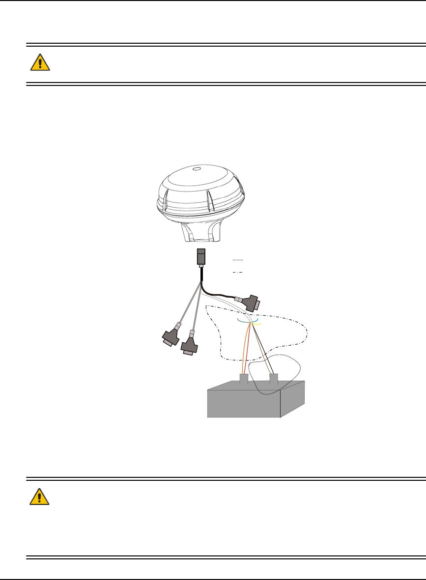
SMART-V1 Power Warning
When connecting power to the SMART-V1 (1), it is recommended that you use a battery source (3).
In this case, it is important that you tie together the bare wires (2) tagged as GND2 (brown) and GND
(black) to the battery’s negative terminal. Tie the bare wires tagged as PWR (red) and PWR2 (orange)
to the battery’s positive terminal.
WARNING: If you do not use a battery, you must tie together the bare wires tagged as GND2
(brown), GND (black) and DIGGND (green) to the DC power supply’s negative
ground connector.
Failure to tie the appropriate grounds, as explained in this section, may result
in your SMART-V1 becoming permanently damaged and void your warranty.
1
+-
3
C
OM1
COM2
PWR
(red)
PWR2
(orange)
TIMEMARK (blue)
Reserved (yellow)
DIG GND (green)
GND2
(brown)
GND
(black)
2
DC
AC
12 OEMV Family Installation and Operation User Manual Rev 5B
Notice
Lightning Protection Notice
What is the hazard?
A lightning strike into the ground causes an increase in the earth's potential causing a high voltage
potential between the centre conductor and shield of the coax cable. Voltages directly applied onto the
centre conductor "roll off" and arrive after the shield pulse producing a high voltage potential between
the centre conductor and shield of the coax cable.
Hazard Impact
A lightning strike causes the ground potential in the area to rise to dangerous levels resulting in
personnel harm or destruction of electronic equipment in an unprotected environment. It also conducts
a portion of the strike energy down the inner conductor of the coax cable to the connected equipment.
Actions to Mitigate Lightning Hazards
1. Do not install the external antenna lines extra-building during a lightning storm.
2. It is not possible to avoid overvoltages caused by lightning, but a lightning protection device may
be used to shunt a large portion of the transient energy to the building ground reducing the over
voltage condition as quickly as possible.
3. Primary lightning protection must be provided by the operator/customer according to local
building codes as part of the extra-building installation.
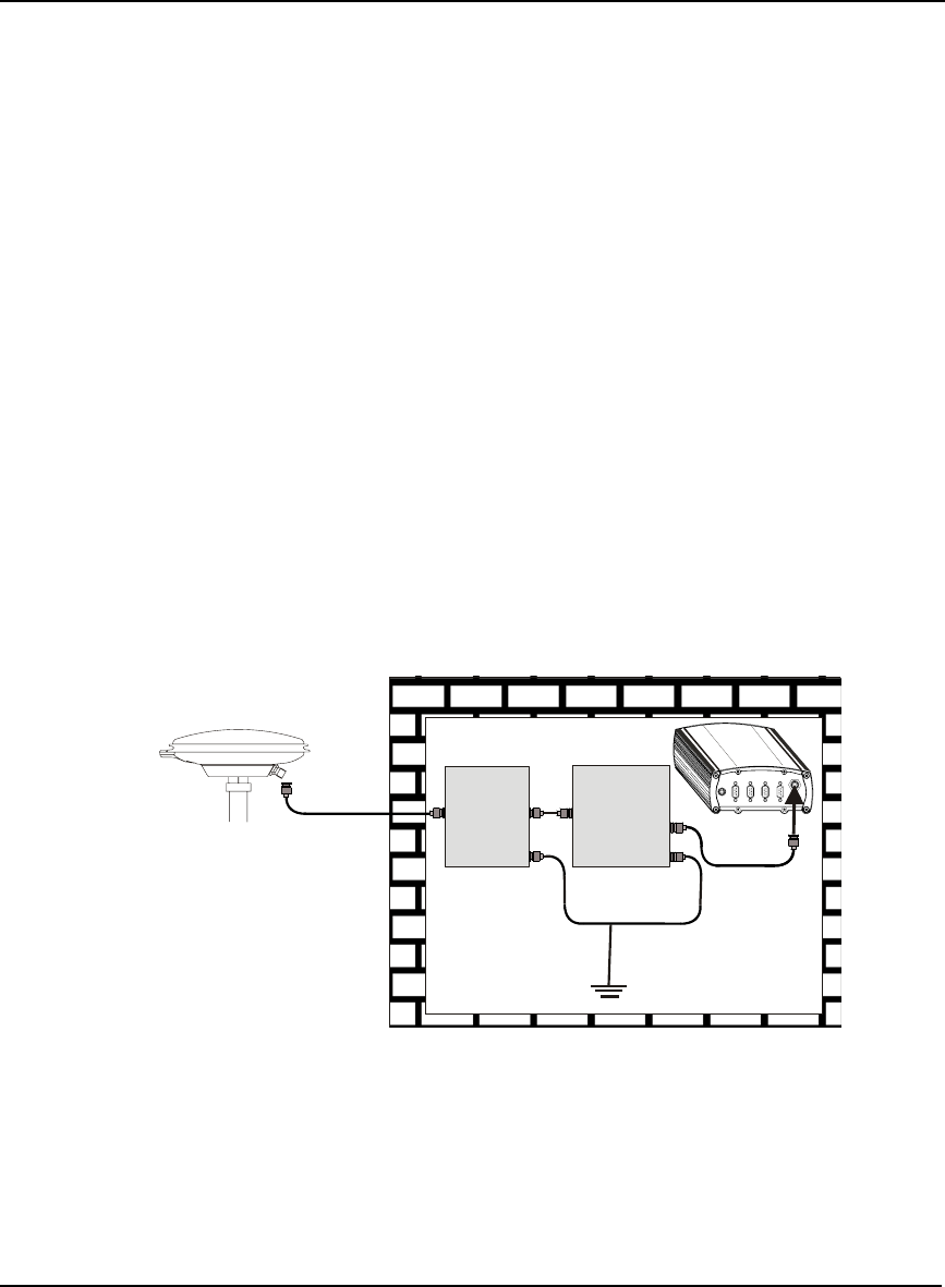
4. NovAtel recommends installing a secondary lightning protection device. The coaxial cable
entering the building is connected to protective ground through the primary and secondary
lightning protection.
Figure 1: Primary and Secondary Lightning Protection
Reference Description Reference Description
1 Primary Lightning Protection Device 4 OEMV Receiver
2 Secondary Lightning Protection Device 5 To Ground
3 External Antenna
12
3
4
5

Notice
OEMV Family Installation and Operation User Manual Rev 5B 13
Electromagnetic Compatibility (EMC) and Safety
Regulatory Testing (DL-V3)
• FCC, Part 15 Radiated Emissions, Class A
• EN 55022 Emissions, Class A
• EN 55024 Immunity
• EN 61000-4-2 Electrostatic Discharge Immunity
• EN 61000-4-3 Radiated RF EM Field Immunity Test
• EN 61000-4-4 Electrical Fast Transient/Burst Test
• EN 61000-4-6 Conducted Immunity
• EN 61000-4-8 Magnetic Field Immunity
• EN 60950 Safety of Information Technology Equipment
Regulatory Testing (ProPak-V3)
• FCC, Part 15 Radiated Emissions, Class B
• EN 55022 Radiated Emissions, Class B
• EN 61000-6-2 Generic Immunity, Industrial Environment
• EN 61000-4-2 Electrostatic Discharge Immunity
• EN 61000-4-3 Radiated RF EM Field Immunity Test
• EN 61000-4-4 Electrical Fast Transient/Burst Test
• EN 61000-4-6 Conducted Immunity
• EN 61000-4-8 Magnetic Field Immunity
• EN 60950 Safety of Information Technology Equipment
Regulatory Testing (FlexPak-V1/FlexPak-V1G/FlexPak-V2)
• FCC, Part 15 Radiated Emissions, Class B
• EN 55022 Emissions: FlexPak-V1G, Class B or FlexPak-V1/FlexPak-V2, Class A
• EN 61000-6-2 Generic Immunity, Industrial Environment
• EN 61000-4-2 Electrostatic Discharge Immunity
• EN 61000-4-3 Radiated RF EM Field Immunity Test
• EN 61000-4-4 Electrical Fast Transient/Burst Test
• EN 61000-4-5 Surge Immunity
• EN 61000-4-6 Conducted Immunity
• EN 61000-4-8 Magnetic Field Immunity
• EN 60950-1 Safety of Information Technology Equipment
Regulatory Testing (SMART-V1)
• FCC, Part 15 Radiated Emissions, Class A
• EN 55022 Emissions, Class A
• EN 61000-6-2 Generic Immunity, Industrial Environment
• EN 60950-1 Safety of Information Technology Equipment
• American Society of Agricultural Engineers (ASAE) Engineering Practice (EP)
Vibration (Random) MIL-STD-801F 514.5 C17 and Vibration (Sine) SAE EP455
• Military Standard (MIL STD) 810 F: 7.7 g RMS Random Vibration, Shock, Sand
and Dust, and Salt Spray

14 OEMV Family Installation and Operation User Manual Rev 5B
Notice
WEEE Notice
If you purchased your OEMV family product in Europe, please return it to your dealer or supplier at
the end of its life. The objectives of the European Community's environment policy are, in particular,
to preserve, protect and improve the quality of the environment, protect human health and utilise
natural resources prudently and rationally. Sustainable development advocates the reduction of
wasteful consumption of natural resources and the prevention of pollution. Waste electrical and
electronic equipment (WEEE) is a regulated area. Where the generation of waste cannot be avoided, it
should be reused or recovered for its material or energy. WEEE products may be recognised by their
wheeled bin label ( ). 1
RoHS Notice
The DL-V3, ProPak-V3, FlexPak-V2, FlexPak-V1G, FlexPak-V1, and SMART-V1 are compliant
with the European Union (EU) Restriction of Hazardous Substances (RoHS) Directive 2002/95/EC.
(The OEMV-1, OEMV-1G, OEMV-2 and OEMV-3 cards are also compliant.) 1
1. Please visit the NovAtel website at http://www.novatel.com/support/weee.htm for more
information on WEEE and RoHS.

OEMV Family Installation and Operation User Manual Rev 5B 15
Software License
Software License
BY INSTALLING, COPYING, OR OTHERWISE USING THE SOFTWARE PRODUCT, YOU AGREE
TO BE BOUND BY THE TERMS OF THIS AGREEMENT. IF YOU DO NOT AGREE WITH THESE
TERMS OF USE, DO NOT INSTALL, COPY OR USE THIS ELECTRONIC PRODUCT (SOFTWARE,
FIRMWARE, SCRIPT FILES, OR OTHER ELECTRONIC PRODUCT WHETHER EMBEDDED IN THE
HARDWARE, ON A CD OR AVAILABLE ON THE COMPANY WEB SITE) (hereinafter referred to as
"Software").
1. License: NovAtel Inc. ("NovAtel") grants you a non-exclusive, non-transferable license (not a sale)
to, where the Software will be used on NovAtel supplied hardware or in conjunction with other NovAtel
supplied software, use the Software with the product(s) as supplied by NovAtel. You agree not to use
the Software for any purpose other than the due exercise of the rights and licences hereby agreed to
be granted to you.
2. Copyright: NovAtel owns, or has the right to sublicense, all copyright, trade secret, patent and other
proprietary rights in the Software and the Software is protected by national copyright laws, international
treaty provisions and all other applicable national laws. You must treat the Software like any other copy-
righted material except that you may make one copy of the Software solely for backup or archival pur-
poses (one copy may be made for each piece of NovAtel hardware on which it is installed or where
used in conjunction with other NovAtel supplied software), the media of said copy shall bear labels
showing all trademark and copyright notices that appear on the original copy. You may not copy the
product manual or written materials accompanying the Software. No right is conveyed by this Agree-
ment for the use, directly, indirectly, by implication or otherwise by Licensee of the name of NovAtel, or
of any trade names or nomenclature used by NovAtel, or any other words or combinations of words
proprietary to NovAtel, in connection with this Agreement, without the prior written consent of NovAtel.
3. Patent Infringement: NovAtel shall not be liable to indemnify the Licensee against any loss sus-
tained by it as the result of any claim made or action brought by any third party for infringement of any
letters patent, registered design or like instrument of privilege by reason of the use or application of the
Software by the Licensee or any other information supplied or to be supplied to the Licensee pursuant
to the terms of this Agreement. NovAtel shall not be bound to take legal proceedings against any third
party in respect of any infringement of letters patent, registered design or like instrument of privilege
which may now or at any future time be owned by it. However, should NovAtel elect to take such legal
proceedings, at NovAtel's request, Licensee shall co-operate reasonably with NovAtel in all legal
actions concerning this license of the Software under this Agreement taken against any third party by
NovAtel to protect its rights in the Software. NovAtel shall bear all reasonable costs and expenses
incurred by Licensee in the course of co-operating with NovAtel in such legal action.
4. Restrictions: You may not:
(a) copy (other than as provided for in paragraph 2), distribute, transfer, rent, lease, lend, sell or
sublicense all or any portion of the Software except in the case of sale of the hardware to a
third party;
(b) modify or prepare derivative works of the Software;
(c) use the Software in connection with computer-based services business or publicly display
visual output of the Software;
(d) transmit the Software over a network, by telephone or electronically using any means (except
when downloading a purchased up[grade from the NovAtel web site); or
(e) reverse engineer, decompile or disassemble the Software.
You agree to keep confidential and use your best efforts to prevent and protect the contents of the Soft-

16 OEMV Family Installation and Operation User Manual Rev 5B
Software License
ware from unauthorized disclosure or use.
5. Term and Termination: This Agreement and the rights and licences hereby granted shall continue
in force in perpetuity unless terminated by NovAtel or Licensee in accordance herewith. In the event
that the Licensee shall at any time during the term of this Agreement: i) be in breach of its obligations
hereunder where such breach is irremediable or if capable of remedy is not remedied within 30 days of
notice from NovAtel requiring its remedy; then and in any event NovAtel may forthwith by notice in writ-
ing terminate this Agreement together with the rights and licences hereby granted by NovAtel. Lic-
ensee may terminate this Agreement by providing written notice to NovAtel. Upon termination, for any
reasons, the Licensee shall promptly, on NovAtel's request, return to NovAtel or at the election of
NovAtel destroy all copies of any documents and extracts comprising or containing the Software. The
Licensee shall also erase any copies of the Software residing on Licensee's computer equipment. Ter-
mination shall be without prejudice to the accrued rights of either party, including payments due to
NovAtel. This provision shall survive termination of this Agreement howsoever arising.
6. Warranty: NovAtel does not warrant the contents of the Software or that it will be error free. The
Software is furnished "AS IS" and without warranty as to the performance or results you may obtain by
using the Software. The entire risk as to the results and performance of the Software is assumed by
you. See product enclosure, if any for any additional warranty.
7. Indemnification: NovAtel shall be under no obligation or liability of any kind (in contract, tort or oth-
erwise and whether directly or indirectly or by way of indemnity contribution or otherwise howsoever) to
the Licensee and the Licensee will indemnify and hold NovAtel harmless against all or any loss, dam-
age, actions, costs, claims, demands and other liabilities or any kind whatsoever (direct, consequential,
special or otherwise) arising directly or indirectly out of or by reason of the use by the Licensee of the
Software whether the same shall arise in consequence of any such infringement, deficiency, inaccu-
racy, error or other defect therein and whether or not involving negligence on the part of any person.
8. Disclaimer and Limitation of Liability:
(a) THE WARRANTIES IN THIS AGREEMENT REPLACE ALL OTHER WARRANTIES,
EXPRESS OR IMPLIED, INCLUDING ANY WARRANTIES OF MERCHANTABILITY OR
FITNESS FOR A PARTICULAR PURPOSE. NovAtel DISCLAIMS AND EXCLUDES ALL
OTHER WARRANTIES. IN NO EVENT WILL NovAtel's LIABILITY OF ANY KIND
INCLUDE ANY SPECIAL, INCIDENTAL OR CONSEQUENTIAL DAMAGES, INCLUDING
LOST PROFITS, EVEN IF NovAtel HAS KNOWLEDGE OF THE POTENTIAL LOSS OR
DAMAGE.
(b) NovAtel will not be liable for any loss or damage caused by delay in furnishing the Software or
any other performance under this Agreement.
(c) NovAtel's entire liability and your exclusive remedies for our liability of any kind (including lia-
bility for negligence) for the Software covered by this Agreement and all other performance or
non-performance by NovAtel under or related to this Agreement are to the remedies specified
by this Agreement.
9. Governing Law: This Agreement is governed by the laws of the Province of Alberta, Canada. Each
of the parties hereto irrevocably attorns to the jurisdiction of the courts of the Province of Alberta.
10. Customer Support: For Software UPDATES and UPGRADES, and regular customer support,
contact the NovAtel GPS Hotline at 1-800-NOVATEL (U.S. or Canada only), or +1-403-295-4900, Fax
+1-403-295-4901, e-mail to support@novatel.ca,
website: http://www.novatel.com or write to:
NovAtel Inc.
Customer Service Department
1120 - 68 Avenue NE,
Calgary, Alberta, Canada T2E 8S5

17 OEMV Family Installation and Operation User Manual Rev 5B
Warranty
Warranty
NovAtel Inc. warrants that its products are free from defects in materials and workmanship, subject to
the conditions set forth below, for the following periods of time, from the date of sale:
OEMV Card Receivers One (1) Year
DL-V3, ProPak-V3, FlexPak-V2, FlexPak-V1, FlexPak-V1G and SMART-V1 One (1) Year
GPSAntenna™ Series One (1) Year
Cables and Accessories Ninety (90) Days
Computer Discs Ninety (90) Days
Software Warranty One (1) Year
Date of sale shall mean the date of the invoice to the original customer for the product. NovAtel’s
responsibility respecting this warranty is solely to product replacement or product repair at an
authorized NovAtel location, or in the case of software, provision of a software revision for
implementation by the customer.
Determination of replacement or repair will be made by NovAtel personnel or by technical personnel
expressly authorized by NovAtel for this purpose.
There are no user serviceable parts in the NovAtel receiver and no maintenance is required. When the
status code indicates that a unit is faulty, replace with another unit and return the faulty unit to
NovAtel Inc.
Once you have obtained an RMA number, you will be advised of proper shipping procedures to return
any defective product. When returning any product to NovAtel, please return the defective product in
the original packaging to avoid ESD and shipping damage.
THE FOREGOING WARRANTIES DO NOT EXTEND TO (I) NONCONFORMITIES, DEFECTS OR ERRORS
IN THE PRODUCTS DUE TO ACCIDENT, ABUSE, MISUSE OR NEGLIGENT USE OF THE PRODUCTS OR
USE IN OTHER THAN A NORMAL AND CUSTOMARY MANNER, ENVIRONMENTAL CONDITIONS NOT
CONFORMING TO NOVATEL’S SPECIFICATIONS, OR FAILURE TO FOLLOW PRESCRIBED INSTALLA-
TION, OPERATING AND MAINTENANCE PROCEDURES, (II) DEFECTS, ERRORS OR NONCONFORMI-
TIES IN THE PRODUCTS DUE TO MODIFICATIONS, ALTERATIONS, ADDITIONS OR CHANGES NOT
MADE IN ACCORDANCE WITH NOVATEL’S SPECIFICATIONS OR AUTHORIZED BY NOVATEL, (III) NOR-
MAL WEAR AND TEAR, (IV) DAMAGE CAUSED BY FORCE OF NATURE OR ACT OF ANY THIRD PER-
SON, (V) SHIPPING DAMAGE; OR (VI) SERVICE OR REPAIR OF PRODUCT BY THE DEALER WITHOUT
PRIOR WRITTEN CONSENT FROM NOVATEL. IN ADDITION, THE FOREGOING WARRANTIES SHALL
NOT APPLY TO PRODUCTS DESIGNATED BY NOVATEL AS BETA SITE TEST SAMPLES, EXPERIMENTAL,
DEVELOPMENTAL, PREPRODUCTION, SAMPLE, INCOMPLETE OR OUT OF SPECIFICATION PROD-
UCTS OR TO RETURNED PRODUCTS IF THE ORIGINAL IDENTIFICATION MARKS HAVE BEEN
REMOVED OR ALTERED. THE WARRANTIES AND REMEDIES ARE EXCLUSIVE AND ALL OTHER WAR-
RANTIES, EXPRESS OR IMPLIED, WRITTEN OR ORAL, INCLUDING THE IMPLIED WARRANTIES OF
MERCHANTABILITY OR FITNESS FOR ANY PARTICULAR PURPOSE ARE EXCLUDED. NOVATEL SHALL
NOT BE LIABLE FOR ANY LOSS, DAMAGE, EXPENSE, OR INJURY ARISING DIRECTLY OR INDIRECTLY
OUT OF THE PURCHASE, INSTALLATION, OPERATION, USE OR LICENSING OR PRODUCTS OR SER-
VICES. IN NO EVENT SHALL NOVATEL BE LIABLE FOR SPECIAL, INDIRECT, INCIDENTAL OR CONSE-
QUENTIAL DAMAGES OF ANY KIND OR NATURE DUE TO ANY CAUSE.
Before shipping any material to NovAtel or Dealer, please obtain a Return Material Authorization (RMA)
number from the point of purchase. You may also visit our website at http://www.novatel.com and select
Support | Repair Requests from the top menu.

18 OEMV Family Installation and Operation User Manual Rev 5B
Customer Service
Customer Service
Firmware upgrades are firmware releases, which increase basic functionality of the receiver from one
model to a higher level model type. When available, upgrades may be purchased at a price, which is
the difference between the two model types on the current NovAtel Inc. Price List plus a nominal
service charge.
Firmware upgrades are accomplished through NovAtel authorized dealers.
Contact your local NovAtel dealer first for more information. To locate a dealer in your area or if the
problem is not resolved, contact NovAtel Inc. directly using one of the following methods:
Call the NovAtel Hotline at 1-800-NOVATEL (U.S. & Canada), or +1-403-295-4900 (international)
Fax: +1-403-295-4901
E-mail: support@novatel.ca
Website: http://www.novatel.com
Write:
NovAtel Inc.
Customer Service Department
1120 - 68 Avenue NE
Calgary, AB
Canada, T2E 8S5
Before contacting NovAtel Customer Service regarding software concerns, please do the
following:
1. Issue a FRESET command
2. Log the following data to a file on your PC for 30 minutes
RXSTATUSB once
RAWEPHEMB onchanged
RANGEB ontime 1
BESTPOSB ontime 1
RXCONFIGA once
VERSIONB once
3. Send the file containing the log to NovAtel Customer Service, using either the NovAtel ftp
site at ftp://ftp.novatel.ca/incoming or the support@novatel.com e-mail address.
If there is a hardware problem that has not been resolved, please send a list of the troubleshooting
steps you have taken and their result. See also Chapter 8, Troubleshooting on Page 124.

OEMV Family Installation and Operation User Manual Rev 5B 19
Foreword
Foreword
Thank you for purchasing a NovAtel receiver card. Whether it is stand-alone or in an enclosure, this
manual will help you get the hardware operational and provide further general information.
Afterwards, the OEMV Firmware Reference Manual will be your primary OEMV family command
and logging reference source.
Scope
The OEMV Family Installation and Operation User Manual contains sufficient information on the
installation and operation of the OEMV-1, OEMV-1G, OEMV-2 and OEMV-3 cards to allow you to
effectively integrate and fully operate them. Enclosures for the OEMV Family cards, the DL-V3,
ProPak-V3, FlexPak-V2, FlexPak-V1G, FlexPak-V1 and the SMART-V1 Antenna, are also described
in this manual. All are RoHS compliant. Please call your distributor, or NovAtel directly, for updated
information on model availability.
After the addition of accessories, user-supplied data communications equipment and a power supply,
the receiver is ready to go.
The OEMV family receivers utilize a comprehensive user-interface command structure, which
requires communications through its communications (COM) ports. The OEMV Firmware Reference
Manual, lists and describes the various receiver commands and logs referenced in this manual. Please
remember that since each receiver is shipped from the distributor with a customer-specific list of
features, such as L-Band, Satellite-Based Augmentation System (SBAS) or GLONASS availability,
some commands or logs may not be applicable to your model. Other supplementary manuals may be
included on CD or as quick start guides to accommodate special models and software features with
unique functionality. It is recommended that you keep these documents and CDs together for easy
reference.
It is beyond the scope of this manual to provide details on service or repair. Please contact your local
NovAtel dealer for any customer-service related inquiries, see Customer Service on Page 18.
What’s New in Rev 6 of this Manual?
This manual has been revised to include information on the following:
• OEMV-1G and FlexPak-V1G GLONASS products are new to the OEMV Family
• OEMV GLONASS models have software capable of full code and real-time
kinematic (RTK) positioning with the 3.200 firmware release
The most up-to-date version of this manual and any related addendum can be downloaded from the
Documentation Updates section of the NovAtel website at www.novatel.com.
Prerequisites
The OEMV-1, OEMV-1G, OEMV-2 and OEMV-3 are OEM products requiring the addition of an
enclosure and peripheral equipment before becoming fully functional Global Navigation Satellite
Systems (GNSS) receivers. The installation chapters of this document provide information concerning
the installation requirements and considerations for the OEMV family cards.

20 OEMV Family Installation and Operation User Manual Rev 5B
Chapter 1 Introduction
1.1 Overview of the OEMV Family
The OEMV family offers single, dual and triple-frequency GNSS receivers and the first integrated L-
band capability without the need for a separate board. The OEMV-based products are GLONASS-
enabled and are capable of full code and real-time kinematic (RTK) positioning.
This family is a group of high-performance GNSS receivers capable of receiving and tracking
different combinations of GPS L1 C/A, L2C, L2 P(Y) and L5 code and carrier, GLONASS L1 and L2
code and carrier, and L-Band (CDGPS and OmniSTAR) on a maximum of 72 channels. SBAS support
is standard on all OEMV family receivers. OEMV adaptability offers multi-system, frequency, and
size configurations for any application requirement. Refer to the GPS+ Reference Manual for an
overview of each of the above signal types, available from our website at http://www.novatel.com/
support/docupdates.htm.
Patented Pulse Aperture Correlator (PAC) with multipath mitigation technologies, and a powerful 32-
bit processor, enable the OEMV family of receivers to offer multipath-resistant processing at high
data update rates. Excellent acquisition and re-acquisition times allow the receivers to operate in
environments where very high dynamics and frequent interruption of signals can be expected.
The OEMV-2 and OEMV-3 are equipped with our new AdVance RTK engine for RT-2. This means a
lower ambiguity error rate, faster narrow lane convergence (even at long baseline lengths) and more
fixes in a wider range of conditions.
In addition, the OEMV family offers system integrators unparalleled flexibility in areas such as
configuration and specification of output data and control signals. Multiple software models are
available, allowing you to better fit the receiver performance to the application while maintaining the
option for a compatible upgrade path.
The RoHS-compliant OEMV family includes the OEMV-1, OEMV-1G, OEMV-2 and OEMV-3 cards,
the DL-V3, ProPak-V3, FlexPak-V2, FlexPak-V1G and FlexPak-V1 enclosures, and the SMART-V1
Antenna. The cards, provided as printed circuit boards, are ideal for custom integration.
1.1.1 Common Features
All OEMV family receivers have the following standard features:
• 14 L1 and 2 SBAS channels
• PAC technology, refer to the Multipath section of the GPS+ Reference Manual
• Fast reacquisition
• Fully field-upgradeable firmware
• Low power consumption
• 20 Hz raw data and position output rates
• Two mark inputs for triggering the output of logs on external events
• Auxiliary strobe signals, including a configurable PPS output for time synchronization
and mark inputs
Introduction Chapter 1
OEMV Family Installation and Operation User Manual Rev 5B 21
• An extensive command and log set for maximum customization
• Outputs to drive external LEDs
1.2 OEMV Cards
The OEMV family cards consist of a single printed circuit board with integrated radio frequency (RF)
and digital sections. They are designed for flexibility of integration and configuration. After
installation with a power source, mounting structure, GNSS, and data communications equipment,
NovAtel’s OEMV cards are ready for the most demanding surveying, positioning, and navigation
applications.
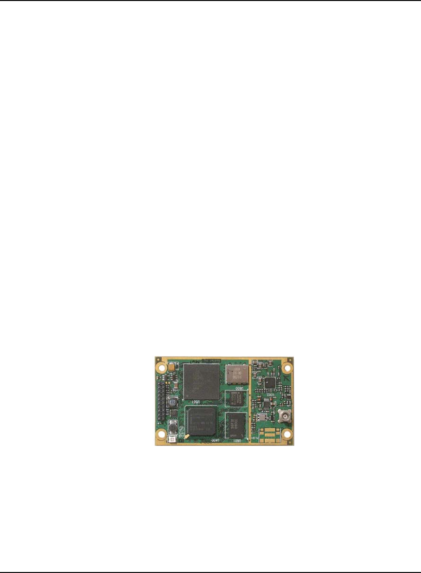
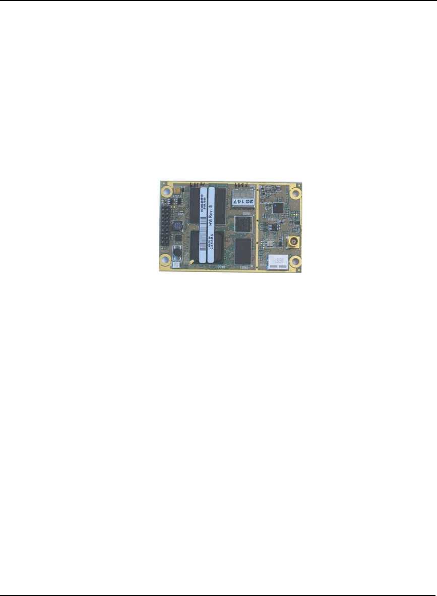
1.2.1 OEMV-1 Card
The OEMV-1 is a compact, low-power, single frequency L1 GPS card with integrated L-Band
(OmniSTAR/CDGPS). In addition to the functionality given in Section 1.1.1 on Page 20, the OEMV-
1 offers:
• 1 Controller Area Network (CAN) Bus port (without transceiver), 1 USB 1.1
communication port and 2 LV-TTL communication ports
• Integrated L-Band (OmniSTAR VBS and CDGPS)
• Auxiliary strobe signals for status and synchronization
• Software load compatibility with other OEMV family products
• Optional Application Program Interface (API) software for loading a custom application
Included with the OEMV is a wrist-grounding strap to prevent ESD damage when handling the card
and a CD containing NovAtel’s PC utilities and product documentation.
For technical specifications on the OEMV-1, please see Section A.2 starting on Page 130.
Figure 2: OEMV-1 Card
22 OEMV Family Installation and Operation User Manual Rev 5B
Chapter 1 Introduction
1.2.2 OEMV-1G Card
The OEMV-1G is a compact, low-power, single frequency L1 GPS card with integrated GLONASS
L1. In addition to the functionality given in Section 1.1.1 on Page 20 and Section 1.2.1 on Page 21,
the OEMV-1G offers:
• 12 GLONASS L1 channels
• GPS real-time 20 cm (RT20) capability, see RT-20 Performance starting on Page 95
• GPS plus GLONASS RTK positioning
Included with the OEMV-1G is a wrist-grounding strap to prevent ESD damage when handling the
card and a CD containing NovAtel’s PC utilities and product documentation.
For technical specifications on the OEMV-1G, please see Section A.2 starting on Page 130.
Figure 3: OEMV-1G Card
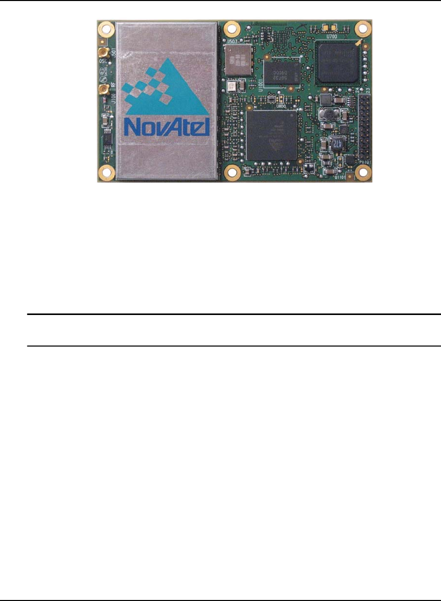
1.2.3 OEMV-2 Card
The OEMV-2 is a GPS plus GLONASS L1/L2 card that is a drop-in replacement for the OEM4-G2L.
In addition to the functionality given in Section 1.1.1 on Page 20, the OEMV-2 offers:
• 14 L2 P(Y) or L2C channels
• 12 GLONASS L1 channels
• 12 GLONASS L2 channels
• AdVance RTK real-time 2 cm (RT-2) positioning capability
• 2 LV-TTL, 1 RS-232 and 1 USB 1.1 communication ports
• CAN Bus (without transceiver) or a second Event line can be software configured
• An external oscillator input
• Auxiliary strobe signals for status and synchronization
• Temperature monitoring and reporting
• Software load compatibility with other OEMV family products
• Optional Application Program Interface (API) software for loading a custom application
Included with the OEMV is a wrist-grounding strap to prevent ESD damage when handling the card
and a CD containing NovAtel’s GPS PC utilities and product documentation.
For technical specifications on the OEMV-2, please see Section A.4 starting on Page 142.
Introduction Chapter 1
OEMV Family Installation and Operation User Manual Rev 5B 23
Figure 4: OEMV-2 Card
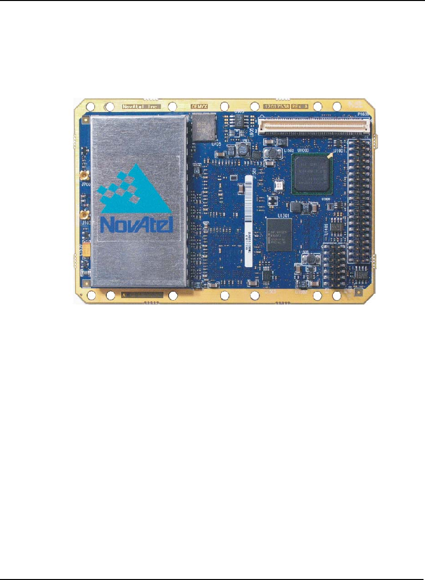
1.2.4 OEMV-3 Card
The OEMV-3 is a GPS L1/L2/L5 plus GLONASS L1/L2 card that is a drop-in replacement for the
OEM4-G2. Triple-frequency capabilities will make the following possible: longer baselines in
differential positioning mode due to the reduction of atmospheric errors, faster resolution of carrier-
phase ambiguities when performing RTK positioning and enhanced positioning precision due to the
additional measurements.
The OEMV-3 is hardware-capable for tracking L5 but requires a future firmware upgrade to
enable L5 positioning. This will be available when a usable number of satellites are in orbit.
In addition to the functionality given in Section 1.1.1 on Page 20, the OEMV-3 offers:
• 14 L2 P(Y) or L2C channels
• 12 GLONASS L1 channels
• 12 GLONASS L2 channels
• 6 L5 channels
• Integrated L-Band (OmniSTAR VBS, HP or XP and CDGPS)
• AdVance RTK real-time 2 cm (RT-2) positioning capability
• 2 CAN Bus (including transceivers), 1 RS-232/RS-422, 1 RS-232, 1 USB 1.1 and 1 LV-
TTL communication ports
• An external oscillator input
• Auxiliary strobe signals for status and synchronization
• On-board power conversion, eliminating the need for external power conditioning
• Voltage and temperature monitoring and reporting
• Software load compatibility with other OEMV family products
24 OEMV Family Installation and Operation User Manual Rev 5B
Chapter 1 Introduction
• Increased memory size and processor speed
• Optional Application Program Interface (API) software for loading a custom application
Included with the OEMV is a wrist-grounding strap to prevent ESD damage when handling the card
and a CD containing NovAtel’s PC utilities and product documentation.
For technical specifications on the OEMV-3 please see Section A.5 starting on Page 148.
Figure 5: OEMV-3 Card

Introduction Chapter 1
OEMV Family Installation and Operation User Manual Rev 5B 25
1.3 OEMV-Based Enclosures
The OEMV-3 can be housed in a DL-V3 or ProPak-V3 enclosure to provide a complete receiver
solution. The OEMV-2, OEMV-1 and OEMV-1G cards can be housed in a FlexPak. The OEMV-1
card can also be housed in a SMART-V1.
When connected to an antenna and a power source, the enclosure and associated OEMV card together
form a fully functioning GNSS receiver.
The enclosures offer protection against environmental conditions and RF interference. In addition,
they provides an easy-to-use interface to the card’s data, power, and status signals.
The table below provides a comparison between the features available on the various enclosures. The
sections that follow give details on each of them.
Table 1: Enclosure Features Comparison
Feature DL-V3 ProPak-V3 FlexPak-V2 FlexPak-V1G FlexPak-V1 SMART-V1
OEM Card
Supported OEMV-3 OEMV-3 OEMV-2 OEMV-1G OEMV-1 OEMV-1
Serial Ports 3
DB-9P
connectors
3
DB-9P
connectors
2
Deutsch
connectors
2
Deutsch
connectors
2
Deutsch
connectors
1
Switchcraft
connector
USB 1.1 Yes Yes Yes Yes Yes On select
models
Ethernet Yes No No No No No
Strobe Port DB-9S
connector DB-9S
connector Deutscha
connector
a. If Pin# 1 on the Deutsch connector is grounded, the COM2 communications mode is set to
RS-422.
Deutscha
connector Deutscha
connector
Switchcraft
connector
Input Voltage +9 to +28 V
DC +9 to +18 V
DC +6 to +18 V +6 to +18 V +6 to +18 V +9 to +28 V
L-Band
Differential
Corrections b
b. A subscription to the OmniSTAR service, or use of the free CDGPS service, is required. Both
services are regional, see Section 5.4 starting on Page 85.
OmniSTAR
(HP, XP or
VBS) and
CDGPS
OmniSTAR
(HP, XP or
VBS) and
CDGPS
Not
available Not
available OmniSTAR
VBS and
CDGPS
OmniSTAR
VBS and
CDGPS
GPS+GLONASS
Positioning Yes Yes Yes Yes c
c. The OEMV-1G-based products have 12 GLONASS L1 channels
Not
available Not
available
AdVance RTK Yes Yes Yes No No No
IMU Support with
SPAN Firmware
Option d
d. If applicable, refer also to your SPAN for OEMV User Manual
Not
available Yes Not
available Not
available Not
available Not
available
26 OEMV Family Installation and Operation User Manual Rev 5B
Chapter 1 Introduction
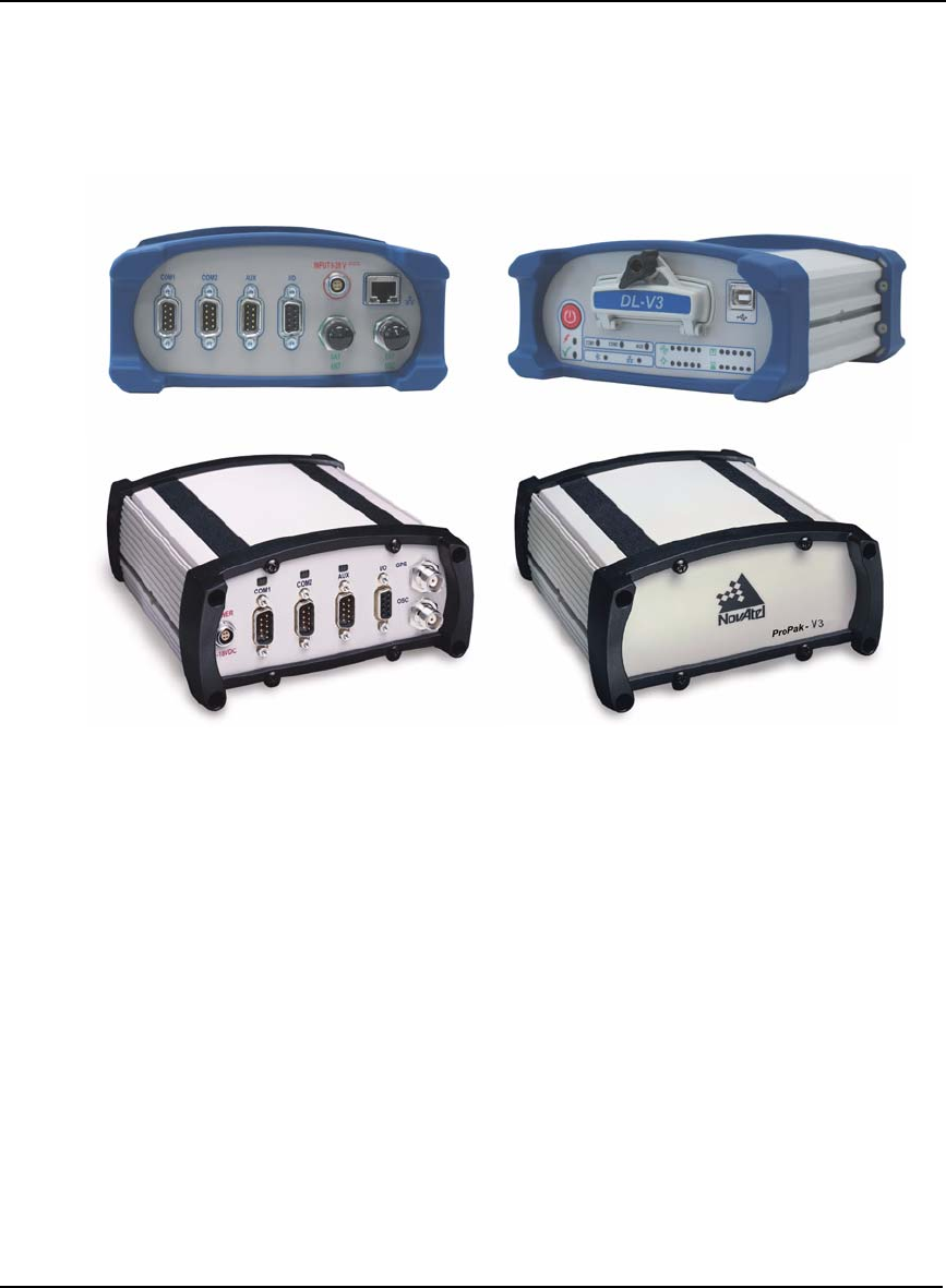
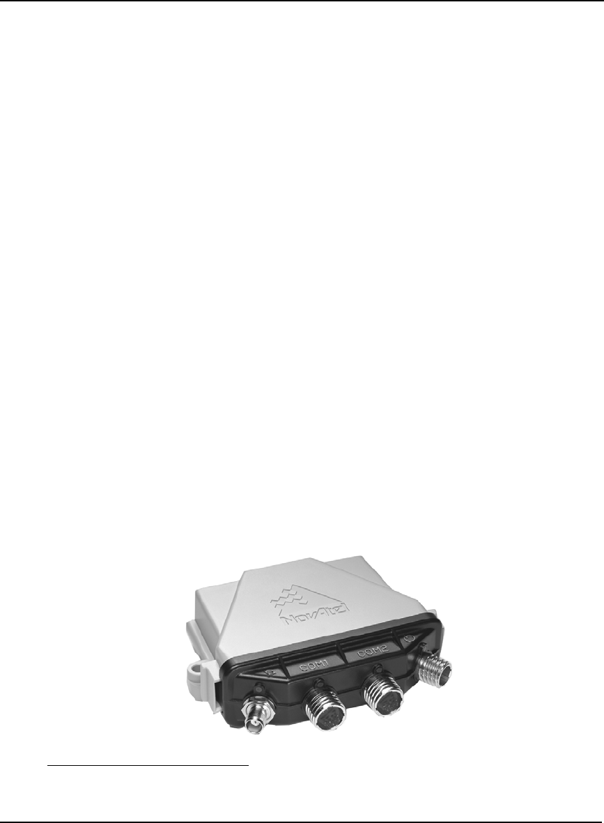
1.3.1 ProPak-V3 and DL-V3
The features of the OEMV-3 are available within the DL-V3 and ProPak-V3. These enclosures, see
Figure 6 below, offer GNSS integrators an effective, self-contained system for indoor applications
while also providing a rugged, water, shock, and vibration resistant housing for outdoor applications.
The DL-V3 is also capable of data logging (DL) using the removable Compact Flash (CF) card.
Figure 6: DL-V3 (top) and ProPak-V3 (bottom) Enclosures
DL-V3
The DL-V3 also offers the following features:
• Rugged waterproof aluminum enclosure with removable compact flash
• Auxiliary status and synchronization signals
• GNSS antenna and power ports
• Bluetooth interaction between the receiver and a user-supplied Bluetooth-equipped
laptop/PDA/PC through COM3. Bluetooth is the default on COM3 but Ethernet
capability is configurable. See also Ethernet Configuration starting on Page 189.
• External oscillator, USB, and Ethernet dedicated connectors
• LED indicators to provide power status, communication status, number of GPS satellites,
CF memory, position mode, occupation time, Bluetooth status and Ethernet status
The following accessories are included with the DL-V3:
• Compact Flash Card for data storage
•Cables:

Introduction Chapter 1
OEMV Family Installation and Operation User Manual Rev 5B 27
• straight through serial
• null modem serial
• I/O
• 12 V power cable
• A CD containing NovAtel’s PC utilities and product documentation
For technical specifications on the DL-V3, please see Section A.6 starting on Page 156.
PROPAK-V3
The ProPak-V3 also offers the following features:
• A rugged waterproof enclosure
• Auxiliary status and synchronization signals
• GNSS antenna and power ports
• Support of peripheral devices, including an Inertial Measurement Unit (IMU) for
combined GPS-inertial navigation, refer to the SPAN for OEMV User Manual
• An external oscillator connector
• Indicators to provide power and communication status
The following accessories are included with the ProPak-V3:
•Cables:
• straight through serial
• null modem serial
• USB serial
• 12 V power cable
• A CD containing NovAtel’s PC utilities and product documentation
For technical specifications on the ProPak-V3, please see Section A.7 starting on Page 163.
28 OEMV Family Installation and Operation User Manual Rev 5B
Chapter 1 Introduction
1.3.2 FlexPak
NovAtel's FlexPak is a rugged, waterproof housing for the OEMV-2, OEMV-1G or OEMV-1 engine.
As a result, the FlexPak can deliver centimeter-level positioning in a compact, lightweight enclosure.
The FlexPak-V2 provides dual-frequency positioning with a USB interface and an API option for
supporting custom applications. Each FlexPak receiver has two SBAS channels. FlexPak-V1G is a
GPS + GLONASS model. There are also FlexPak-V1 GPS + L-Band and FlexPak-V2 GPS +
GLONASS models available.
The FlexPak offers the following features:
• A waterproof, shock and dust resistant enclosure
• Low power consumption
• Two serial ports (COM1 is RS-232 and COM2 is RS-232/RS-4221)
• USB support
• PPS output
• Configurable event inputs
• Indicators for position, communication status and power
The following accessories are included with the FlexPak:
• 12 V power adapter cable
• Data cables
• straight through serial
• null modem serial
• USB serial
• 12V power adapter
• A CD containing NovAtel’s PC utilities and product documentation
For technical specifications on the FlexPak, please see Section A.8 on Page 171.
Figure 7: FlexPak Enclosure
1. If Pin# 1 on the Deutsch connector is grounded, the COM2 communications mode is set to
RS-422.
Introduction Chapter 1
OEMV Family Installation and Operation User Manual Rev 5B 29
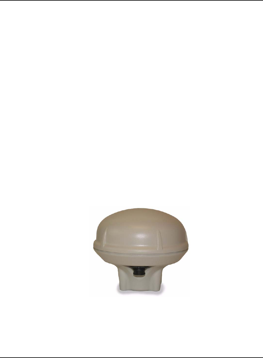
1.3.3 SMART-V1
NovAtel’s SMART-V1 is a rugged, self-contained GPS receiver and antenna. It is specially designed
for harsh tracking environments in a number of applications.
The SMART is available in two side-mount configurations to suit your integration requirements: USB
or CAN.
The SMART-V1 offers the following features:
• A waterproof, shock and dust resistant enclosure
• Environmentally sealed unit is designed to meet or exceed MIL-STD 810
• Low power consumption
• Two serial ports (RS-232)
• USB support on USB models
• CAN Bus support on CAN models
• Configurable event input
• Integrated L-Band capability for OmniSTAR VBS and CDGPS positioning
The following accessories are included with the SMART-V1:
• Quick Start Guide
• CD containing an installation program for NovAtel’s CDU graphical user interface
software, other PC utilities and product documentation, including user manuals
Cables are also available as optional accessories. For technical specifications on the SMART-V1,
including optional cables, please see Section A.9, SMART-V1 starting on Page 179.
Figure 8: SMART-V1 Antenna
30 OEMV Family Installation and Operation User Manual Rev 5B
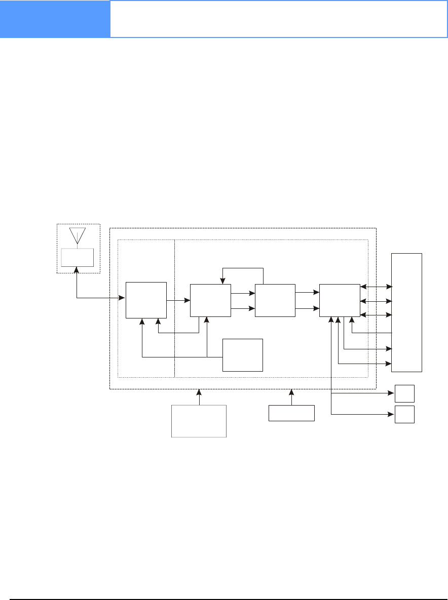
Chapter 2 Receiver System Overview
In addition to a NovAtel OEMV card, a complete GNSS receiver system typically contains four other
major components:
• A custom enclosure and wiring harness
• A GNSS antenna (and optional LNA power supply)
• A power supply
• Data communications equipment
The overall system is represented in Figure 9. A brief description of the Radio Frequency (RF) and
Digital Electronics sections follow the figure. The components above are also described. Details of
installation and set up are provided in Chapter 3, Installation and Set Up on Page 33.
Figure 9: GNSS Receiver System Functional Diagram
Reference Description Reference Description
1 Enclosure 14 Optional LNA Power
2 OEMV Card 15 Power Supply
3 RF Section 16 GNSS Antennaand LNA
4 Digital Section 17 RF, Coaxial Cable and Power
5 Controls 18 Data and Signal Processing
6 RF-IF Sections 19 COM1
7 Signal Processor 20 COM2
8 Clock 21 COM3
1
2
4
35
678910
11
12 13
19
20
21
22
23
24
14 15
16
17
18
25
26

Receiver System Overview Chapter 2
OEMV Family Installation and Operation User Manual Rev 5B 31
9 32-Bit CPU 22 Input Timing Signal
10 System I/O 23 Output Timing Signal
11 AGC 24 USB Communication
12 Clock 25 CAN Communication 1
13 VCTCXO 26 CAN Communication 2
2.1 OEMV Card
NovAtel’s OEMV cards consist of a radio frequency (RF) and a digital electronics section.
2.1.1 Radio Frequency (RF) Section
The receiver obtains a filtered and amplified GNSS signal from the antenna via the coaxial cable. The
RF section performs the translation of the incoming RF signal to an Intermediate Frequency (IF)
signal usable by the digital section. It also supplies power to the active antenna’s LNA through the
coaxial cable while maintaining isolation between the DC and RF paths. The RF section can reject a
high level of potential interference (for example, MSAT, Inmarsat, cellular phone, and TV sub-
harmonic signals).
2.1.2 Digital Electronics Section
The digital section of the receiver receives a down-converted, amplified GNSS signal which it
digitizes and processes to obtain a GNSS solution (position, velocity and time). The digital section
consists of an analog-to-digital converter, a 32-bit system processor, memory, control and
configuration logic, signal processing circuitry, serial peripheral devices, and supporting circuitry.
The digital section performs the translations and calculations necessary to convert the IF analog
signals into usable position and status information. It also handles all I/O functions, including the
auxiliary strobe signals, which are described in detail in Section 3.3.1 on Page 44. For input and
output levels please see Appendix A, Table 31, OEMV-3 Strobes on Page 151, Table 29, OEMV-2
Strobes on Page 145 and Table 25, OEMV-1 Strobes on Page 133.
2.2 Enclosure and Wiring Harness
An enclosure is necessary to protect the OEMV card from environmental exposure and RF
interference. A user-supplied wiring harness is also required to provide an interface to the OEMV
card’s antenna and power inputs and data and status signals.
2.3 GNSS Antenna
The purpose of the GNSS antenna is to convert the electromagnetic waves transmitted by the GNSS
satellites into RF signals. An active GNSS antenna is required for the receiver to function properly.
NovAtel’s active antennas are recommended because of their precise phase centres and robust
enclosures.

32 OEMV Family Installation and Operation User Manual Rev 5B
Chapter 2 Receiver System Overview
2.3.1 Optional LNA Power Supply
Power for the antenna LNA is normally supplied by the receiver but not, for example, by the OEMV-
2 card. If a different type of antenna is required that is incompatible with this supply, then you could
connect an external power source to the receiver. See also Antenna LNA Power on Page 51.
2.4 Principal Power Supply
A single external power supply capable of delivering the minimum receiver voltage necessary to
operate the receiver. Minimum voltage varies per card, see Table 3, Voltage Input Range for OEMV on
Page 35 and Appendix A, Technical Specifications on Page 129 for details.
WARNING: If the voltage supplied is below the minimum specification, the receiver will
suspend operation. If the voltage supplied is above the maximum specification,
the receiver may be permanently damaged, voiding your warranty.
2.5 Data Communications Equipment
A PC, laptop or other data communications equipment is necessary to communicate with the receiver
and, if desired, to store data generated by the receiver.
OEMV Family Installation and Operation User Manual Rev 5B 33
Chapter 3 Installation and Set Up
This chapter contains instructions and tips to set up your NovAtel receiver to create a GNSS receiver
system similar to that described in Chapter 2, Receiver System Overview on Page 30.
3.1 Additional Equipment Required
In order for the receiver to perform optimally, the following additional equipment is required:
• An interface for power, communications, and other signals and an enclosure to
protect against the environment
• A NovAtel GNSS antenna
• A quality coaxial cable (and interconnect adapter cable as necessary)
• Data communication equipment capable of serial communication
• A serial cable (if not included with the receiver)
• A power supply
• A power cable (if not included with the receiver)
CAUTION: When the OEMV family receiver is installed in a permanent location, such as in
a building, it should be protected by a lightning protection device according to
local building codes. See also Warranty on Page 17.
3.1.1 Selecting a GNSS Antenna
An active antenna is required because its low-noise amplifier (LNA) boosts the power of the incoming
signal to compensate for the line loss between the antenna and the receiver.
NovAtel offers a variety of single and dual-frequency GNSS antenna models, as indicated in Table 2
on Page 34. All include band-pass filtering and an LNA. The GNSS antenna you choose will depend
on your particular application. Each of these models offer exceptional phase-center stability as well as
a significant measure of immunity against multipath interference. Each one has an environmentally-
sealed radome. The ANT-532, ANT-533, ANT-534, ANT-536, ANT-537, ANT-538, GPS-702L, GPS-
701GG and GPS-702GG are RoHS compliant.

34 OEMV Family Installation and Operation User Manual Rev 5B
Chapter 3 Installation and Set Up
Table 2: NovAtel GNSS Antenna Models
3.1.2 Choosing a Coaxial Cable
An appropriate coaxial cable is one that matches the impedance of the antenna and receiver being used
(50 ohms), and whose line loss does not exceed 10.0 dB. If the limit is exceeded, excessive signal
degradation occurs and the receiver may not be able to meet its performance specifications. NovAtel
offers a variety of coaxial cables to meet your GNSS antenna interconnection requirements, including:
• 5, 15, or 30 m antenna cables with TNC male connectors on both ends (NovAtel
part numbers C006, C016 and C032 respectively)
• 22 cm interconnect adapter cable between the MCX (OEMV-1/OEMV-1G) or
MMCX (OEMV-2/OEMV-3) and the TNC connectors (NovAtel part #GPS-C002)
Note that a conversion is required between the female MCX connector on the OEMV-1 and OEMV-
1G, the male MMCX connector on the OEMV-2, or the male MMCX connector on the OEMV-3, and
the female TNC connector on NovAtel’s GNSS antennas.
Your local NovAtel dealer can advise you about your specific configuration. If your application
requires the use of cable longer than 30 m, refer to the application note RF Equipment Selection and
Installation on our website at www.novatel.com, or you can obtain it directly from NovAtel.
High-quality coaxial cables should be used because a mismatch in impedance, possible with lower
quality cable, produces reflections in the cable that increase signal loss. Though it is possible to use
other high-quality antenna cables, the performance specifications of the OEMV family receivers are
warranted only when used with NovAtel-supplied accessories.
3.1.3 Power Supply Requirements
This section contains information on the requirements for the input power to the receiver. See
Appendix A, Technical Specifications starting on Page 129 for more power supply specifications.
WARNING: If the voltage supplied is below the minimum specification, the receiver will
suspend operation. If the voltage supplied is above the maximum specification,
the receiver may be permanently damaged, voiding your warranty.
Models Frequencies Supported GPS GLONASS
701, 511, 521, 536, 537 L1 only 98
702, 532, 533 L1 and L2 98
702L, 534 L1 and L2 plus L-Band 98
701GGL, 538 L1 plus L-Band 99
701GG L1 only 99
702GGL L1 and L2 plus L-Band 99
702GG L1 and L2 99

Installation and Set Up Chapter 3
OEMV Family Installation and Operation User Manual Rev 5B 35
OEMV Cards
The OEMV card contains a DC to DC converter that is very tolerant to noise and ripple at its input. A
tightly regulated input supply to the OEMV-3 card is not required, as long as it falls within the given
input range. A tightly regulated input supply to the OEMV-1, OEMV-1G or OEMV-2 card is required.
The power supply used for any OEMV card should be capable of 5 W. The voltage input range for
each the OEMV cards is given in Table 3 on Page 35.
Table 3: Voltage Input Range for OEMV
All members of the OEMV family receivers are designed to prevent internal damage when subjected
to a reverse polarity power connection. The OEMV also provides protection for a short duration
during over-voltage events. It is recommended that appropriate fuses or current limiting be
incorporated as a safety precaution on all power lines used. Use a sufficient gauge of wire to ensure
that the voltage at the connector is within the OEMV card’s requirements.
DL-V3, ProPak-V3, FlexPak-V2, FlexPak-V1G, FlexPak-V1 or SMART-V1 Enclosures
The DL-V3, ProPak-V3, FlexPak-V2, FlexPak-V1G and FlexPak-V1 enclosures are supplied with a
12V power adapter with a built-in 3 A slow-blow fuse for use with a standard 12 V DC power outlet.
In the case of the DL-V3, you can choose to press its power button or wait for the power sequence,
when it will monitor the serial ports, as long as a valid voltage is present at the power supply input, see
DL-V3 Power Down and the Power Button on Page 40.
If a different supply is desired, the table below provides the input range and type of connector required
to mate with the enclosure’s power connector. The supply should be capable of 5 W.
Table 4: Enclosure Power Requirements
OEMV Card Power Input Range
OEMV-1 +3.3 V DC +5%/-3%
OEMV-1G +3.3 V DC +5%/-3%
OEMV-2 +3.3 V DC +5%/-3%
OEMV-3 +4.5 to +18 V DC
Enclosure Power Cable Connector Required Power Input Range
DL-V3 4-pin LEMO socket connector a labelled PWR
a. See Appendix D, Replacement Parts on Page 213 for connector part numbers.
+9 to +28 V DC
ProPak-V3 4-pin LEMO socket connector a labelled PWR +6 to +18 V DC b
b. +9 to +18 V DC when connected to an IMU. If applicable, see the SPAN Technology User
Manual for more information.
FlexPak-
V1/V1G/V2 3-pin Deutsch socket connector a labelled +6 to +18 V DC
SMART-V1 18-pin Switchcraft connector (not labelled) c
c. Bare wires on the optional cables are labelled PWR, PWR2, GND and GND2, see also
Table 43 on Page 184
+9 to +28 V DC

36 OEMV Family Installation and Operation User Manual Rev 5B
Chapter 3 Installation and Set Up
3.2 Installation Overview
Once you have selected the appropriate equipment, complete the following steps to set up and begin
using your NovAtel GNSS receiver.
1. Install the OEMV card in an enclosure with a wiring harness, as described in Section 3.2.1 on
Page 36.
2. Mount the GNSS antenna to a secure, stable structure, as described in Section 3.2.3 on Page 39.
3. Connect the GNSS antenna to the receiver using an antenna RF cable, using the information
given in Section 3.2.4 on Page 40.
4. Apply power to the receiver, as described in Section 3.2.5 on Page 40.
5. Connect the receiver to a PC or other data communications equipment by following the informa-
tion given in Section 3.2.6 on Page 41.
3.2.1 Installing an OEMV Card in a Wiring Harness and Enclosure
To install an OEMV card, begin with the following:
1. Ensure you are taking the necessary precautions against ESD, as described in this section below.
2. Mount the OEMV card in a secure enclosure to reduce environmental exposure and RF interfer-
ence, as described in this section in Mounting the Printed Circuit Board starting below.
3. Prepare a wiring harness to interface to the receiver’s data, status, and power signals using the
information given in Preparing the Data, Signal & Power Harness starting on Page 37.
Electrostatic Discharge (ESD) Precautions
Electrostatic discharge is a leading cause of failure of electronic equipment components and printed
circuit boards containing ESD-sensitive devices and components. It is imperative that ESD
precautions be followed when handling or installing an OEMV card. Refer to the Anti-Static Practices
section of the GPS+ Reference Manual for more information on ESD precautions.
Leave the OEMV card in its static-shielding bag or clamshell when not connected in its normal
operating environment. When removing the OEMV card from the ESD protection, follow accepted
standard anti-static practices. Failure to do so may cause damage to the OEMV card.
When you remove the OEMV card from the original packing box, it is recommended that you save the
box and ESD protection for future storage or shipment purposes.
CAUTION
•Always wear a properly grounded anti-static wrist strap when handling the OEMV card.
• Always hold the OEMV card by its corners or the RF shield, and avoid direct contact with any
of the components.
• Do not let the OEMV card come in contact with clothing at any time because the grounding strap
cannot dissipate static charges from fabrics.

Installation and Set Up Chapter 3
OEMV Family Installation and Operation User Manual Rev 5B 37
• Failure to follow accepted ESD handling practices could cause damage to the OEMV card.
• Warranty may be voided if equipment is damaged by ESD.
Mounting the Printed Circuit Board
The OEMV family cards are OEM products and therefore the printed circuit board is provided without
a housing structure. This allows flexibility in creating a mounting environment to suit particular
product and marketing requirements. The mounting and enclosure should provide the following:
• mounting of external connectors
• protection from hostile physical environments (for example, rain, snow, sand, salt,
water, extreme temperatures)
• electromagnetic shielding to protect from hostile RF environments (for example,
nearby transmitters)
• electromagnetic shielding so that the final product itself conforms to RF emissions
specifications
Integrator note: The card can not pass emissions testing by itself. It must be in an enclosure.
For example, the ProPak-V3 passes regulatory emissions as shown in the Notice starting on
Page 10. For more information on emissions testing, please refer to the regulatory body in
your geographic area. For example, in North America that is the Federal Communications
Commission (FCC) and in Europe the Conformité Européenne (CE).
• protection from ESD (see Appendix B, Electrostatic Discharge Control (ESD)
Practices starting on Page 186)
The OEMV card can be held in place by screws when used in a custom assembly. Please see Appendix
A, Technical Specifications starting on Page 129 for mechanical drawings.
Preparing the Data, Signal & Power Harness
The wiring harness serves the following interconnect functions:
• provide access to the serial communications ports
• provide access to input and output timing strobes
• provide power input(s)
• provide access to control signals
For all OEMV cards, the power, status, and data inputs and outputs are accessed from a single
connector. Therefore, the harness must be designed to mate with this connector.
As shown in Figures 10, 11 and 12, the OEMV cards use a 20, 24 or 40-pin header for the data, power,
and status signals. The RF input is a female MCX connector. An external oscillator input is available
on the OEMV-2 and OEMV-3 dual frequency cards where the oscillator input is also a female MMCX
connector. The pin outs for these connectors are specified in Appendix A, Technical Specifications
starting on Page 129 for the OEMV-1, OEMV-1G, OEMV-2 and OEMV-3 while their manufacturers’
part numbers are in Section D.5 on Page 213.
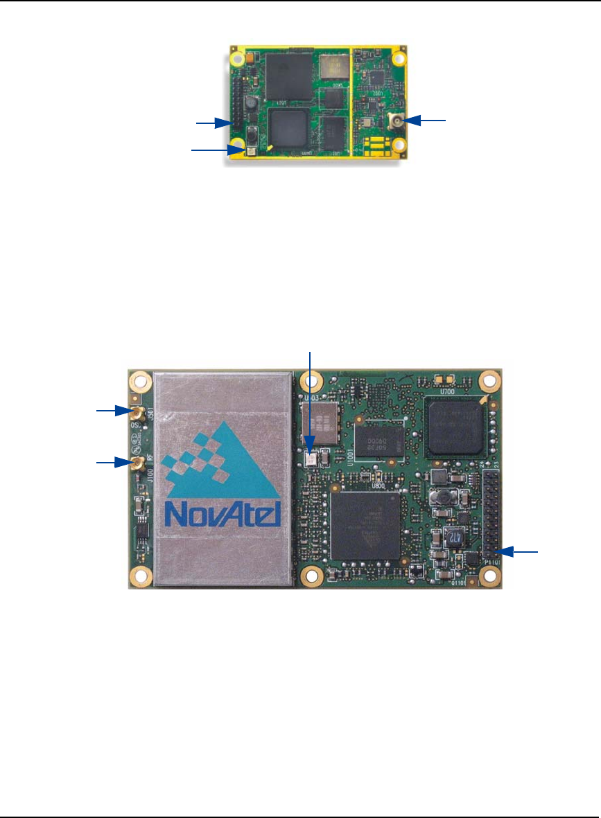
38 OEMV Family Installation and Operation User Manual Rev 5B
Chapter 3 Installation and Set Up
Figure 10: OEMV-1 and OEMV-1G Connector and Indicator Locations
.Reference Description
1 J700 power, data, and signal connector (20 pin dual row male connector
with a 2 mm straight 2 x 10 header)
2 LED status indicator
3 J100 RF signal input and LNA power output (MCX female connector)
Figure 11: OEMV-2 Connector and Indicator Locations
Reference Description
1 P1101 power, data, and signal connector (24 pin dual row male connector
with a 2 mm straight 2 x 12 header)
2 LED status indicator
3 J100 RF signal input and LNA power output (MMCX female connector)
4 J501 external oscillator input (MMCX female connector)
13
2
1
3
2
4
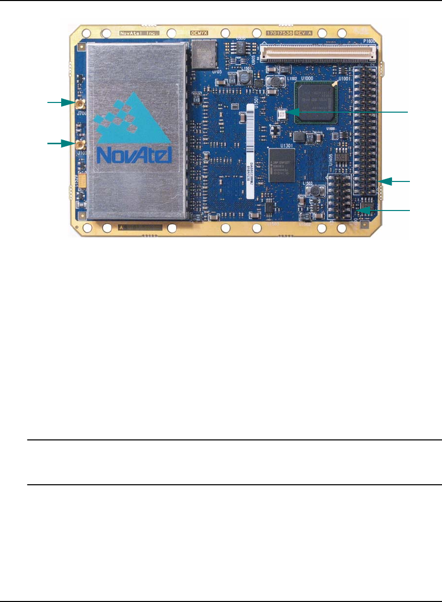
Installation and Set Up Chapter 3
OEMV Family Installation and Operation User Manual Rev 5B 39
Figure 12: OEMV-3 Connector and Indicator Locations
Reference Description
1 P1601 power, data, and signal connector (40 pin dual row male connector
with 0.025” square pins and 0.1” spacing)
2 LED status indicator
3 J100 RF signal input and LNA power output (MMCX female connector)
4 J700 external oscillator input (MMCX female connector)
5 P1400 CAN Bus connector with transceiver
3.2.2 Mounting Bracket (DL-V3 and ProPak-V3 Only)
Along with the DL-V3 and ProPak-V3 enclosures, mounting kits are provided to facilitate mounting
the receivers to a surface.
The mounting kits are not designed for use in high-dynamics/vibration environments. Contact
NovAtel if your application needs the DL-V3 or ProPak-V3 to be mounted in this type of
environment.
To install the mounting bracket provided with the DL-V3 or ProPak-V3, refer to the instructions
provided with the mounting kit. Page 164 provides the dimension information for the bracket.
3.2.3 Mounting the GNSS Antenna
Once the OEMV card is installed in a wiring harness and enclosure, the antenna to be used with the
receiver must be mounted. The GNSS receiver has been designed to operate with any of the NovAtel
single-frequency or dual-frequency GNSS antenna models. See Section 3.1.1 on Page 33 for more
1
2
3
4
5

40 OEMV Family Installation and Operation User Manual Rev 5B
Chapter 3 Installation and Set Up
information.
When installing the antenna system:
• Choose an antenna location that has a clear view of the sky so that each satellite
above the horizon can be tracked without obstruction. (Refer to the Multipath
section in the GPS+ Reference Manual).
• Mount the antenna on a secure, stable structure capable of safe operation in the
specific environment.
3.2.4 Connecting the Antenna to the Receiver
Connect the antenna to the receiver using high-quality coaxial cable, as discussed in Section 3.1.2 on
Page 34.
The DL-V3, ProPak-V3 and FlexPak enclosures provide a TNC female connector, which can be
connected to the antenna directly with any of NovAtel’s coaxial cables. For the OEMV cards, an
interconnect adapter cable is required to convert the TNC male end of the coaxial cable to the card’s
MCX (OEMV-1/OEMV-1G) or MMCX (OEMV-2/OEMV-3) female RF input connector. The
location of the RF connector for the each of the OEMV cards is shown in Appendix A, Technical
Specifications starting on Page 129.
The SMART-V1 is a combined receiver and antenna, therefore no external antenna connection is
necessary.
3.2.5 Applying Power to the Receiver
Connect the power supply, set to the voltage given in Table 3, Voltage Input Range for OEMV on Page
35, to the wiring harness created previously.
For a DL-V3, ProPak-V3, FlexPak-V1, FlexPak-V1G, FlexPak-V2 or SMART-V1, connect a power
supply to the power port. For the DL-V3 you can choose to press its power button or wait for the
power sequence, see DL-V3 Power Down and the Power Button starting below. See also Table 4,
Enclosure Power Requirements on Page 35.
DL-V3 Power Down and the Power Button
DL-V3 incorporates a power button on its front end-cap, see Figure 6 on Page 26. Pressing this
switch, sends a signal to the microprocessor to turn on or off the GNSS receiver.
The DL-V3 has a low-power mode called power-down mode. To enter this low-power mode, press the
power button for at least three but no more than seven seconds, then release it. This is also the mode
the receiver enters into after applying power.
In the power-down mode, all logging is disabled.
While power consumption in power-down mode is minimal, less than 10 μA, the DL-V3 is not
completely off. If power conservation is important in your application, disconnect the power source
from the DL-V3 when it is not in use.
Press the power button momentarily to turn the DL-V3 back on. Also, the DL-V3 monitors its serial
ports, and becomes fully operational as soon as serial port activity is detected. For example, if a key is

Installation and Set Up Chapter 3
OEMV Family Installation and Operation User Manual Rev 5B 41
pressed on a handheld data logger that is plugged into one of the DL-V3's serial ports, the time
required to come on is only a few seconds. However, it may require an additional few minutes to
establish an initial time and position. During power-down and power-up time, the serial ports do not
process data. You must wait until the receiver outputs an RXSTATUSA log with a BOOTOK message
before typing any commands.
The automatic power-down feature is disabled when logging is in progress. However, if the power
button is pressed while the DL-V3 is logging data autonomously, the DL-V3 saves any open data files
and then goes into power-down mode.
An additional function of the power button is that it resets the DL-V3 if it is held depressed for at least
10 seconds. This system reset clears stored logging parameters and reverts to a factory configuration
when the power button is released.
3.2.6 Connecting Data Communications Equipment
In order to communicate with the receiver by sending commands and obtaining logs, a connection to
some form of data communications equipment is required. In the case of the DL-V3, your laptop/PC
can also communicate with the receiver using the Bluetooth interface. The default configuration
available for each of the receiver types, except for the SMART-V1, is given in Table 5 on Page 41.
Details on the SMART-V1 port can be seen in Table 6, at the bottom of this page, and its pin-out
tables, in Appendix A on Page 181, for both USB and CAN models.
However, if desired, on some of the receivers, the serial ports can be factory configured for either RS-
232, RS-422, or LVTTL operation. Consult NovAtel Customer Service for more details on factory
configuration. See Appendix A, Technical Specifications starting on Page 129 for data connection
details.
Table 5: Default Serial Port Configurations
Receiver COM1 COM2 COM3 AUX
OEMV-1/
OEMV-1G LVTTL LVTTL USB D+ (default) N/A
OEMV-2 RS-232 LVTTL LVTTL N/A
OEMV-3 RS-232 / RS-422, see
User-Selectable Port
Configuration starting
on Page 43
Factory-configurable
RS-232 \ LVTTL LVTTL N/A
DL-V3 RS-232 RS-232 Bluetooth (default)
or Ethernet RS-232
ProPak-V3 Factory-
configurable
RS-232 \ RS-422
RS-232 Factory-
configurable
RS-232 \ RS-422 a
N/A
FlexPak-
V1/V1G/V2 RS-232 RS-232 / RS-422, see
User-Selectable Port
Configuration starting
on Page 43
Not available N/A
a. The COM3 port on the ProPak-V3 is labelled AUX.

42 OEMV Family Installation and Operation User Manual Rev 5B
Chapter 3 Installation and Set Up
Table 6: SMART-V1 Port Configuration (RS-232 only)
Each port may support some, or all, of the following signals:
• Data Terminal Ready (DTR)
• Clear To Send (CTS)
• Transmitted Data (TXD)
• Request To Send (RTS)
• Received Data (RXD)
• Data Carrier Detect (DCD)
On many of the receivers, extra control lines are provided on COM2 for use with modems or other
differential correction data links.
The DL-V3, ProPak-V3 and FlexPak enclosures are Data Terminal Equipment (DTE) so that TXD,
RTS and DTR are outputs while RXD, CTS and DCD are inputs. A null modem cable, supplied with
the receiver, is required to connect to another DTE like a terminal or a PC, while a straight cable is
used to connect to another receiver.
The port settings (bit rate, parity, and so on) are software-configurable. These are further described in
Chapter 4, Operation on Page 56. See Appendix A, Technical Specifications starting on Page 129 for
further information on data communications characteristics.
The SMART-V1 multi-cable is available in four configurations: two for the USB and two for the CAN
model. All 4 cables are 3 m in length. Table 7 on Page 43 illustrates the models and their cable
options. See also the SMART-V1 antenna cable pinouts and drawings in Appendix A, Technical
Specifications starting on Page 183.
Model Ports
USB The single port on the
USB model of the
SMART-V1 can be used
for COM1, COM2 or USB
CAN The single port on the
CAN model of the
SMART-V1 can be used
for COM1, CAN or COM3

Installation and Set Up Chapter 3
OEMV Family Installation and Operation User Manual Rev 5B 43
Table 7: SMART-V1 Cable Options (RS-232 only)
User-Selectable Port Configuration
The FlexPak-V1, FlexPak-V1G and FlexPak-V2 are RS-232/RS-422-selectable through pin 1 of
COM2, see Table 38, FlexPak COM2 Port Pin-Out Descriptions on Page 174 and Section A.8.2.2 on
Page 176.
The ProPak-V3 is not user-selectable but can be factory-configured on both COM1 and COM3 for
RS-232 or RS-422 operation, see Table 36, ProPak-V3 I/O Port Pin-Out Descriptions on Page 165.
The DL-V3 is RS-232 only but its COM3 port has Bluetooth/Ethernet configuration options. See DL-
Model Cables Part Numbers Connector Ends
USB SMART-V1 COM1/COM2/USB 01017893 USB: USB plug
DB9: COM1 female
COM2 female
Bare tagged wire: PWR
PWR2
GND
GND2
RESERVED
TIMEMARK
DIGITAL GND
SMART-V1 Variant 01017923 Bare tagged wire: USB
COM1
COM2
PWR
PWR2
GND
GND2
RESERVED
TIMEMARK
DIGITAL GND
CAN SMART-V1 COM1/CAN/COM3 01017894 DB9: CAN1 male
COM3 female
COM1 female
Bare tagged wire: PWR
PWR2
GND
GND2
RESERVED
TIMEMARK
DIGITAL GND
SMART-V1 Variant 01017922 Bare tagged wire: CAN1
COM3
COM1
PWR
PWR2
GND
GND2
RESERVED
TIMEMARK
DIGITAL GND

44 OEMV Family Installation and Operation User Manual Rev 5B
Chapter 3 Installation and Set Up
V3 COM3 Configuration starting on Page 44.
The OEMV-3 offers a user-selectable configuration for the COM1 port.
For OEMV-3, the configuration is selected using the USERIO1 pin. By default, RS-232 is selected as
the USERIO1 input is set LOW by an internal pull-down resistor. To select RS-422 upon startup,
apply 3.3 V to USERIO1. Alternatively, tie USERIO1 to pin 38 of the 40-pin connector on the
OEMV-3.
Pin 38, on the 40-pin connector, is usually an ERROR indicator, and during normal OEMV card
operations is set LOW, but for < 2 s during OEMV card initialization, immediately after applying
power to the OEMV card, this pin is set HIGH at 3.3 Volts. It drops to LOW <2 s later when the
OEMV card has been fully booted up and the [COMx] prompt is output from the OEMV card on all
COM ports.
USERIO1 needs to be initialized HIGH during this initial boot-up phase in order to set up the COM1
port for RS-422 mode. Therefore, tie pin 38 to a 3.3 V source to trigger the USERIO1, to set the
COM1 port to RS-422 mode.
DL-V3 COM3 Configuration
You can switch between Ethernet and Bluetooth (default) on COM3 using the APPCONTROL
command. In the case of switching to Ethernet, power is automatically applied to it after switching.
Bluetooth, on the other hand, may be in sleep mode. If Bluetooth operation is required, it must be put
into active mode using the COMVOUT command. The ethenet requires more setup configuration
steps. These involve configuring serial, and network, parameters. See also Appendix C starting on
Page 189 for details.
Further details on the commands above can be found in the DL-V3 Firmware Reference Manual.
3.3 Additional Features and Information
This section contains information on the additional features of the OEMV family receivers, which
may affect the overall design of your receiver system.
3.3.1 Strobes
On OEMV family receivers, a set of inputs and outputs provide status and synchronization signals.
These signals are referred to as strobes. Not all strobe signals are provided on all receivers. However,
for those products for which strobes are available, you may want to design your installation to include
support for these signals.
Pin-out information can also be found in Appendix A:
• OEMV-1 pin-out starting on Page 135
• OEMV-1G pin-out starting on Page 141
• OEMV-2 pin-out starting on Page 147
• OEMV-3 pin-out starting on Page 153
• DL-V3 port pin-out on Page 158
• ProPak-V3 port pin-out on Page 165

Installation and Set Up Chapter 3
OEMV Family Installation and Operation User Manual Rev 5B 45
• FlexPak-V1/V1G/V2 port pin-out starting on Page 173
• SMART-V1 port pin-out on Page 181
3.3.2 Universal Serial Bus (USB)
OEMV family receivers, along with the accompanying NovAtel USB drivers for Windows 2000 and
Windows XP, provide three virtual serial ports over a single USB 1.1 connection using USB D(+) and
USB D(-) signals, see Table 8 below.
Table 8: Available USB Signals on Receivers
The three virtual serial ports, identified by the OEMV receiver as USB1, USB2, and USB3, are
available to existing Windows applications which use COM ports to communicate (for example,
HyperTerminal and CDU). The NovAtel USB drivers assign COM port numbers sequentially
following any existing ports on the PC. For example, if a PC has COM1 and COM2 ports, the
NovAtel USB drivers assign COM3 to USB1, COM4 to USB2, and COM5 to USB3.
Typically, a PC has several physical USB ports. The assignment of COM port numbers is tied
to a USB port on the PC. This allows you to switch receivers without Windows assigning new
COM ports. However, if you connect the receiver to a different physical USB port, Windows
detects the receiver's presence on that USB port and assigns three new COM port numbers.
The NovAtel USB Configuration Utility installed with the NovAtel USB drivers allows you to change
the COM port numbers assigned to the virtual serial ports. The USB drivers, along with installation
instructions, are available on the OEMV Family CD by selecting USB Support from the main menu.
You can also check for updates to the drivers or release notes on our website at www.novatel.com.
CAUTION Do not connect USB ports if USB communications is not being used or you may
risk damaging your receiver.
Receiver Pins/Ports
OEMV-1/OEMV-1G Pin 2 and Pin 3
OEMV-2 Pin 21 and Pin 22
OEMV-3 Pin 3 and Pin 5
DL-V3 Dedicated USB port labelled:
ProPak-V3 COM1 Pins 6 and 9
FlexPak-V1/V1G/V2 COM1 Pins 11 and 12 or COM2 Pins 11 and 12
SMART-V1 a
a. USB model only
Pins 10 and 16

46 OEMV Family Installation and Operation User Manual Rev 5B
Chapter 3 Installation and Set Up
3.3.3 CAN Bus
A Controller Area Network Bus (CAN Bus) is a rugged differential serial bus with a protocol that
provides services for processes, data and network management.
CAN Bus is a generic term, as well as referring to a specific standard for several rugged differential
bus standards that provide services for processes, data, and network management. NovAtel’s
MINOS5 ASIC incorporates a CAN Bus controller and the GPS engine creates and interprets the
physical level signals, and low-level messages, that are compatible with the appropriate sections of the
J1939 and ISO11783 standards. However, the integrator must be aware that there is no single software
standard for such development, and a manufacturer can specify messages that are specific to its
equipment without violating the standards. Accordingly, NovAtel allows integrators to support the
protocol stack they require, to interface to NovAtel’s device drivers, by incorporating this protocol
stack within NovAtel’s Application Program Interface (API). Integrators interested in this option are
advised to contact NovAtel Customer Service for further information.
On the OEMV-1, OEMV-1G and OEMV-2 card, the CAN port is shared with the EVENT2 input on
both cards, the VARF output on the OEMV-1/ OEMV-1G, and the GPIO signal on the OEMV-2. The
OEMV-1, OEMV-1G and OEMV-2 require external CAN transceivers and proper bus terminations.
See Section A.2, OEMV-1 Card on Page 135, or Section A.4, OEMV-2 Card on Page 147, for pin-out
information.
The OEMV-3 has two CAN transceivers, CAN1 and CAN2. See Figure 55, Top-view of 14-Pin CAN
Connector on the OEMV-3 on Page 155. Proper bus termination is required. CAN1 is for slow speed
(up to 125 Kb/s) and CAN2 is for high speed (up to 1 Mb/s). Their CAN interface can be accessed
using NovAtel's API, but requires that shared signals be disabled in order to avoid conflicts. Refer to
the OEMV Firmware Reference Manual and, see also, Table 9 on Page 47.
CAN Bus signals are not available on DL-V3, ProPak-V3 or FlexPak receivers. There is a CAN Bus-
capable model of the SMART-V1 with its own multi-cable.
CAN Bus functionality is controlled through NovAtel’s optional API software. The API
header file includes documentation on using the CAN bus. For example, oemapi.h.

Installation and Set Up Chapter 3
OEMV Family Installation and Operation User Manual Rev 5B 47
Table 9: Available CAN Signals on Receivers
3.3.4 Status Indicators
OEMV family receiver cards have LED indicators that provide the status of the receiver. The OEMV
cards have a single indicator, which is shown in Figure 12 on Page 39 for the OEMV-3. The LED
blinks green on and off at approximately 1 Hz to indicate normal operation. If the indicator is red, then
the receiver is not working properly. The operation of this indicator is further described in Section 7.6
on Page 122.
The enclosures’ status indicators are shown in Tables 10 and 11 below and on Page 48. The LED
status indicators on the front of the DL-V3 are shown in Section 3.3.5 starting on Page 48.
Table 10: ProPak-V3 Status Indicators
Receiver CAN Pins/Ports
OEMV-1 and
OEMV-1G
(no transceiver)
J700
CAN1 Tx Pin 7
CAN1 Rx Pin 6
CAN2 Tx Pin 20
CAN2 Rx Pin 8
OEMV-2
(no transceiver)
P1100
CAN1 Tx Pin 19
CAN1 Rx Pin 7
OEMV-3
(with transceiver)
P1400
CAN1H Pin 2
CAN1L Pin 1
CAN2H Pin 6
CAN2L Pin 5
SMART-V1 CANH Pin 3
CANL Pin 4
Indicator Indicator Color Status
COM1 Green Data is being transmitted from COM1
Red Data is being received on COM1
COM2 Green Data is being transmitted from COM2
Red Data is being received on COM2
AUX Green Data is being transmitted from COM3
Red Data is being received on COM3
PWR Red The receiver is powered

48 OEMV Family Installation and Operation User Manual Rev 5B
Chapter 3 Installation and Set Up
Table 11: FlexPak Status Indicators
3.3.5 DL-V3 Status Indicators
The LEDs on the front of the DL-V3 represent these categories:
• Power
• Receiver Status
• COMs (COM1, COM2 and AUX)
• COM3
• Satellite Tracking
• Flash Card Memory
• Positioning Mode
• Occupation Time
Power
The power indicator glows orange when the receiver is powered and then glows green once the
receiver has been turned on. See also the DL-V3 Power Down and the Power Button section on
Page 40.
Status
The status indicator flashes orange when the receiver is first turned on. Under normal operation,
this LED is off. If a status event occurs, the LED flashes orange again. See also Chapter 7,
Built-In Status Tests starting on Page 118 and the RXSTATUS log.
Communication Ports (excluding COM3)
The top of the COM1, COM2 and AUX LEDs flash GREEN when transmitting data while the
bottom of them flash AMBER when receiving data.
Indicator FlexPak-V1/FlexPak-V1G FlexPak-V2
Antenna/
Position Valid Solid GREEN with valid position /
No error mode Solid GREEN with valid position /
Solid RED indicates a board error
COM1 Flashing GREEN when transmitting
data from COM1 /
Flashing RED when receiving data
on COM1
Flashing GREEN when
transmitting data from COM1 /
Flashing RED when receiving data
on COM1
COM2 Flashing GREEN when transmitting
data from COM1 /
Flashing RED when receiving data
on COM1
Flashing GREEN when
transmitting data from COM1 /
Flashing RED when receiving data
on COM1
Power Solid RED when +12V applied Solid RED when +12V applied
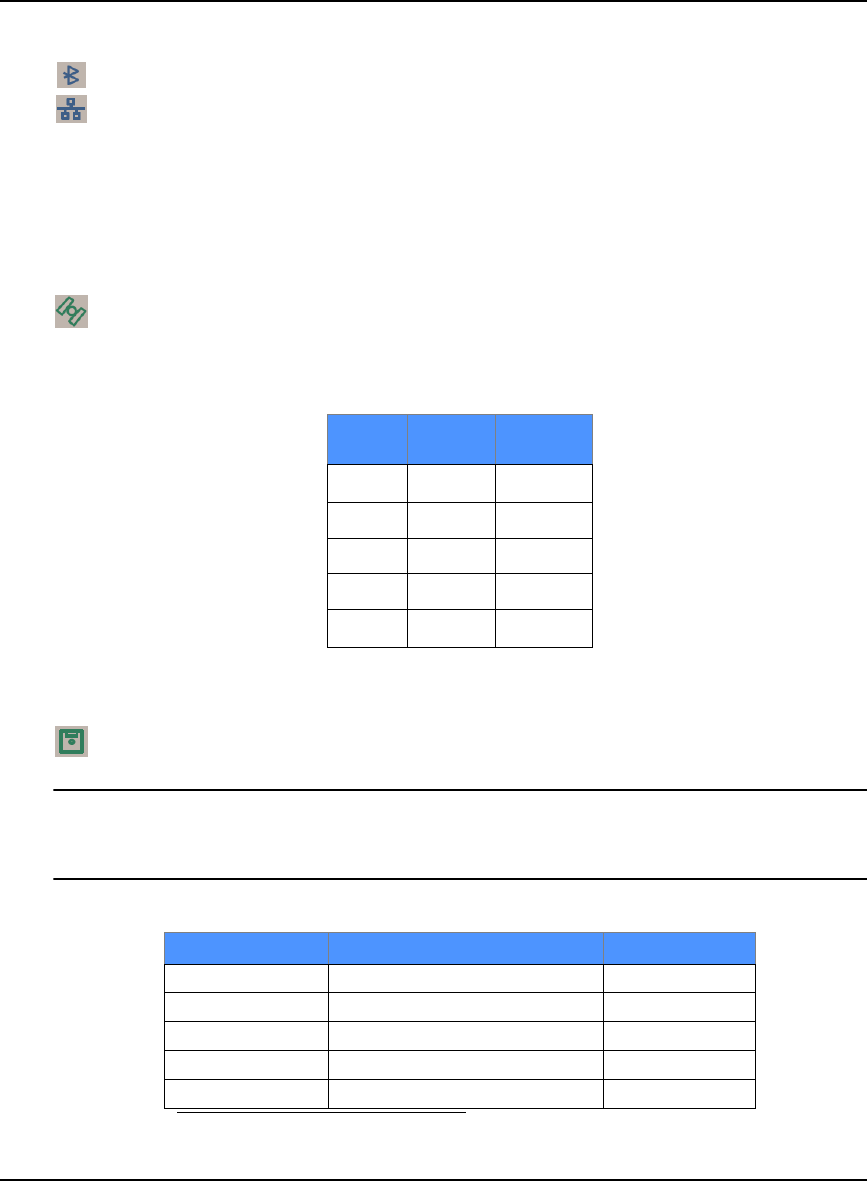
Installation and Set Up Chapter 3
OEMV Family Installation and Operation User Manual Rev 5B 49
COM3
The COM3 section of the LED panel on the front of the DL-V3, has two LEDs:
• 1 for Bluetooth Mode (default)
• 1 for Ethernet Mode
Only one mode may be used at a time on COM3. The active mode’s LED glows (blue for Bluetooth
and orange for Ethernet). See also Appendix C, Ethernet Configuration starting on Page 189.
Satellite Tracking
The LED that is glowing, and its color, corresponds to the number of GPS-only, or GLONASS
and GPS-combined, satellites being tracked by the DL-V3, where the first LED to the left is #1,
see Table 12:
Table 12: Satellite Tracking LEDs
Flash Card Memory
The number of LEDs that are glowing, and their colors, correspond to the amount of memory
left in the DL-V3’s compact flash card, where the first LED to the left is #1, see Table 13.
If all 5 flash card LEDs are flashing, it can mean that there is no compact flash card in the DL-
V3, or that the card in the unit is not formatted (see Section 3.3.8, DL-V3 Removable Compact
Flash Memory Card starting on Page 52).
Table 13: Flash Card Memory LEDs
LED# # of
SVs LED
Color
1≤ 3 Red
2 4 or 5 Amber
3 6 or 7 Green
4 8 or 9 Green
5≥ 10 Green
# of LEDs Capacity LED Color
1 Capacity ≤ 20% Red a
a. This red LED can also mean that the card was not formatted, and
placed in the receiver, when the receiver was powered off.
240% ≥ Capacity > 20% Amber
360% ≥ Capacity > 40% Green
480% ≥ Capacity > 60% Green
5 Capacity > 80% Green

50 OEMV Family Installation and Operation User Manual Rev 5B
Chapter 3 Installation and Set Up
Positioning Mode
Which LEDs are glowing, or blinking, or off, and their colors, correspond to the DL-V3’s
current positioning mode. Table 14 below shows the available positioning modes and their
corresponding LEDs where the first LED to the left is #1, as you look at the DL-V3, and #5 is
the furthest to the right. If the table cell shows the name of a color (red, amber or green) with a
solid background, that LED is glowing solidly. The table cells that appear dim, behind their
color name, indicate that the LED is flashing that color. The LED may also be off.
Table 14: Positioning Mode LEDs
Position Mode Position Mode Detail 1 2 3 4 5
Single Point Autonomous (fixed height) Amber Off Off Off Off
Autonomous (3D) Amber Off Off Off Off
Differential GPS
SBAS Off Green Off Off Off
CDGPS Off Off Green Off Off
DGPS Off Green Green Off Off
OmniSTAR
VBS (searching) Amber Green Off Off Off
VBS (pulling in) Amber Green Off Off Off
VBS Amber Green Off Off Off
XP (searching) Amber Off Green Off Off
XP (pulling in) Amber Off Green Off Off
XP Amber Off Green Off Off
HP (searching) Amber Green Green Off Off
HP (pulling in) Amber Green Green Off Off
HP Amber Green Green Off Off
RTK
Float (RT-20, unconverged) Amber Off Off Green Off
Float (RT-20) Amber Off Off Green Off
Fixed (RT-2, unconverged) Amber Off Off Off Green
Fixed (RT-2) Amber Off Off Off Green

Installation and Set Up Chapter 3
OEMV Family Installation and Operation User Manual Rev 5B 51
Occupation Time
The LED that is glowing green corresponds to the DL-V3’s occupation time gauge. The
occupation time LEDs provide an indication of whether sufficient data has been collected for
successfully post processing data for the indicated baseline. The LED that appears corresponds
to the baseline length that you can process your data to, where the first LED to the left is #1. The
occupation time gauge has the following values from left to right, see Table 15:
Table 15: Occupation Time LEDs
3.3.6 External Oscillator (OEMV-2, OEMV-3, DL-V3 and ProPak-V3 only)
For certain applications requiring greater precision than what is possible using the on-board 20 MHz,
voltage-controlled, temperature-compensated crystal oscillator (VCTCXO), you may wish to connect
the OEMV to an external, high-stability oscillator. The external oscillator can be either 5 MHz or 10
MHz.
Operation consists of connecting a cable from the external oscillator to the receiver’s external
oscillator input connector. For the DL-V3 and ProPak-V3, the BNC external oscillator port, labelled
OSC, is used. See Figure 6, DL-V3 (top) and ProPak-V3 (bottom) Enclosures on Page 26. For the
OEMV-3, an MMCX female connector (J700) is used, as shown in Figure 12 on Page 39. On the
OEMV-2, the external oscillator connector is J501, see Figure 11 on Page 38. The receiver does not
have to be powered down during this procedure. If you are handling the OEMV card directly, anti-
static practices must be observed.
Once the external oscillator has been installed, the EXTERNALCLOCK command must be issued to
define the clock model (for example, cesium, rubidium or ovenized crystal). If the input clock rate is 5
MHz, the EXTERNALCLOCK command must be issued to change the 10 MHz default rate.
3.3.7 Antenna LNA Power
Receiver RF input gain requirements are easily met when using NovAtel antennas and coaxial cables.
NovAtel antennas employ a built-in, low-noise amplifier (LNA), which typically provides 26 dB of
gain to the received satellite signal. The power to the antenna LNA is provided through the center
conductor of the receiver’s RF port. To achieve the required input gain to the receiver, NovAtel
coaxial cables have been designed to exhibit no more than 6 dB loss. Antenna supply over-current
protection is provided on the OEMV cards and is limited to 100mA.
LED# Baseline
Length
(km)
LED
Color
1≤ 5 Green
2> 5
≤ 10 Green
3> 10
≤ 15 Green
4> 15
≤ 20 Green
5≥ 20 Green

52 OEMV Family Installation and Operation User Manual Rev 5B
Chapter 3 Installation and Set Up
The OEMV family receivers and their LNA capabilities are listed in this section.
OEMV-3
For the OEMV-3 it is possible to supply power to the LNA of an active antenna either from the
antenna port of the OEMV-3 card itself or from an external source. The internal antenna power supply
of the OEMV-3 cards can produce +4.75 to +5.10 V DC at up to 100 mA; enough for NovAtel’s dual-
frequency GNSS antennas, so that an additional LNA power supply is not normally required.
If a different antenna is used whose LNA requires voltage capacity beyond what the receiver can
produce, then the external LNA power option must be utilized. This simply requires setting an
external voltage supply between +5.5 and +18 V DC, 100 mA maximum, and connecting it to pin 40
of the 40-pin connector on the OEMV-3. See also Appendix A, OEMV-3, LNA_PWR on Page 154.
In either case, the LNA power is fed to the antenna through the same coaxial cable used for the RF
signals (LNA power is enabled by default). The internal LNA power source should be disabled using
the ANTENNAPOWER command.
OEMV-2
The OEMV-2 card supplies power to the active antenna LNA from its internal LNA supply only.
OEMV-1 and OEMV-1G
The OEMV-1 and OEMV-1G cards use external LNA power only. Set the external voltage supply
between +5.5 and +16 V DC and connect it to pin 1 of the OEMV-1, or OEMV-1G, 20-pin connector.
See also Appendix A, OEMV-1, RF Input / LNA Power Output on Page 131 or OEMV-1G, Page 137.
CAUTION NovAtel guarantees performance specifications only using NovAtel antennas.
3.3.8 DL-V3 Removable Compact Flash Memory Card
Data commands and logs can be recorded from the DL-V3 to a removable Compact Flash (CF) card.
The need for a companion handheld data logger is avoided when continuous user interaction is not
required, since the DL-V3 is capable of logging data according to pre-configured parameters without
any user intervention. In applications when continuous user interaction is required, a simple handheld
controller can be used with the DL-V3, as the controller does not require its own data logging
memory. The reduced handheld data logger or controller requirement simplifies your system and
reduce its total cost and power consumption. By default only a log group named default exists. A
powerup group must be created to take advantage of the automatic functionality, refer to the DL-V3
Firmware Reference Manual for more information.
WARNING: To minimize the possibility of damage, always keep the CF card cover closed and
latched except when exchanging CF cards. Do not change the card while
logging is in progress. Data will be lost. It is not necessary to turn the receiver
off before inserting or extracting a CF card if you are not logging data.

Installation and Set Up Chapter 3
OEMV Family Installation and Operation User Manual Rev 5B 53
An example of a 64 MB CF card is shown in Figure 13 below.
Figure 13: 64 MB Flash Card
When you insert a CF card into the DL-V3, enter a DISK FORMAT command using the Console
window in NovAtel’s Control and Display Unit (CDU) graphical user interface software. Wait a few
minutes and use the DL-V3 power button to turn it off and then on again. When power is returned, the
DL-V3 should be able to recognize and use the CF card. For more information on CDU see Section
6.2, CDU starting on Page 99.
Data Logging
See Section 4.4, Using the DL-V3 starting on Page 63 to begin collecting data.
Collected data can either be transmitted to a host computer over a serial port, or stored on the CF card.
If you choose to log data to the CF card, each logging session is stored in a single, unique file. These
files can then be transferred to a host computer, for data analysis or other types of post-processing, by
one of two methods:
·Transfer the data by means of serial communications, for example, DLVTool in CDU
·Physically remove the CF card from the DL-V3 and insert it into the host computer,
provided that it is also suitably equipped with a CF card port
Refer to the DLVTool chapter, and the DL-V3 commands and logs, detailed in the DL-V3 Firmware
Reference Manual.
Access Door
From Figure 14, Compact Flash Card Door (shown with its latch in the open position) on Page 54,
you can see that the CF card access door is closed with a latch (reference 1 in Figure 14 on Page 54).
As long as the latch is secured, it provides a water and dust-resistant seal around the CF card.
To open the CF card access door, turn the latch counter-clockwise, until it releases the door.
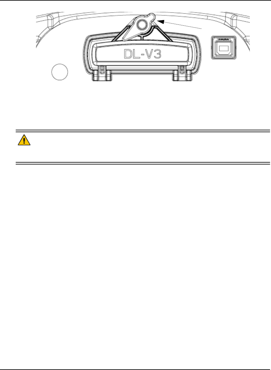
54 OEMV Family Installation and Operation User Manual Rev 5B
Chapter 3 Installation and Set Up
Figure 14: Compact Flash Card Door (shown with its latch in the open position)
To remove the CF card, unlock the access door. When the door is open, you can see an eject button to
the left of the card. You must push this button to partially eject the card. Grasp the card and pull it all
the way out.
WARNING: Do not change the card while logging is in progress. Data will be lost. It is not
necessary to turn the receiver off before inserting or extracting a CF card if you
are not logging data. See Step 4, Stop the Data Logging on Page 64.
To insert the card, ensure that it is correctly aligned before gently sliding it into the slot. When the card
slides all the way in and locks in place, the eject button extends. If you attempt to insert the card
incorrectly, it will not go all the way in, and the eject button will not extend. In this case, do not force
the card! Remove it, orient it properly, and then insert it. After the card is locked in place, close the
cover.
The data logging mechanism is designed to be robust and to endure power interruptions (and similar
disruptive events) with minimum loss of data. In this situation, allow for your data to be possibly
reduced by several seconds up to a maximum of five minutes. When possible, error messages are
generated to identify problems as they arise. See also the RXSTATUS description in Chapter 7, Built-
In Status Tests starting on Page 33.
Card Choice
You have the flexibility of choosing the CF card with the storage capacity that is the most appropriate
for your needs, based on the selected logging rate. This is discussed in greater detail in Section 4.4,
Using the DL-V3 starting on Page 63.
Take for example the case where you have to format and use a CF card (the DL-V3 comes with a 64
MB card but up to a 2 GB card is compatible):
1. Connect your PC to COM1 of the DL-V3 at 9600 bps using a null modem cable with any simple
terminal program, for example, HyperTerminal or CDU.
2. Power on the DL-V3 and wait until you see the BOOTOK message.
3. Type in LOG VERSION in the terminal program and press the <Enter> key to ensure you have a
two-way serial connection with the DL-V3. If you do, a VERSION output message appears. For
1

Installation and Set Up Chapter 3
OEMV Family Installation and Operation User Manual Rev 5B 55
example:
#VERSIONA,COM1,0,75.0,UNKNOWN,0,1608.685,004c0000,3681,2678;
3,GPSCARD,"L12LGRVA","DAB06420097","OEMV3G-3.02-2T2","3.200A10","3.000",
"2007/Feb/20","11:44:36",DB_USERAPPAUTO,"DL-V3","0","","1.000A16","",
"2007/Jan/03","17:39:23",USERINFO,"LMX9820A","0623","","","","",""
*c2605fb9
4. Insert the CF card.
5. Type DISK FORMAT in the terminal program and press the <Enter> key.
6. Wait a minute and power off the DL-V3.
7. Power on the DL-V3 again and the CF card is ready to use.
At least 1% of free space must be available on the CF card to open a log file. On a 64 MB
disk, there is a 0.64 MB allowance for the file table.
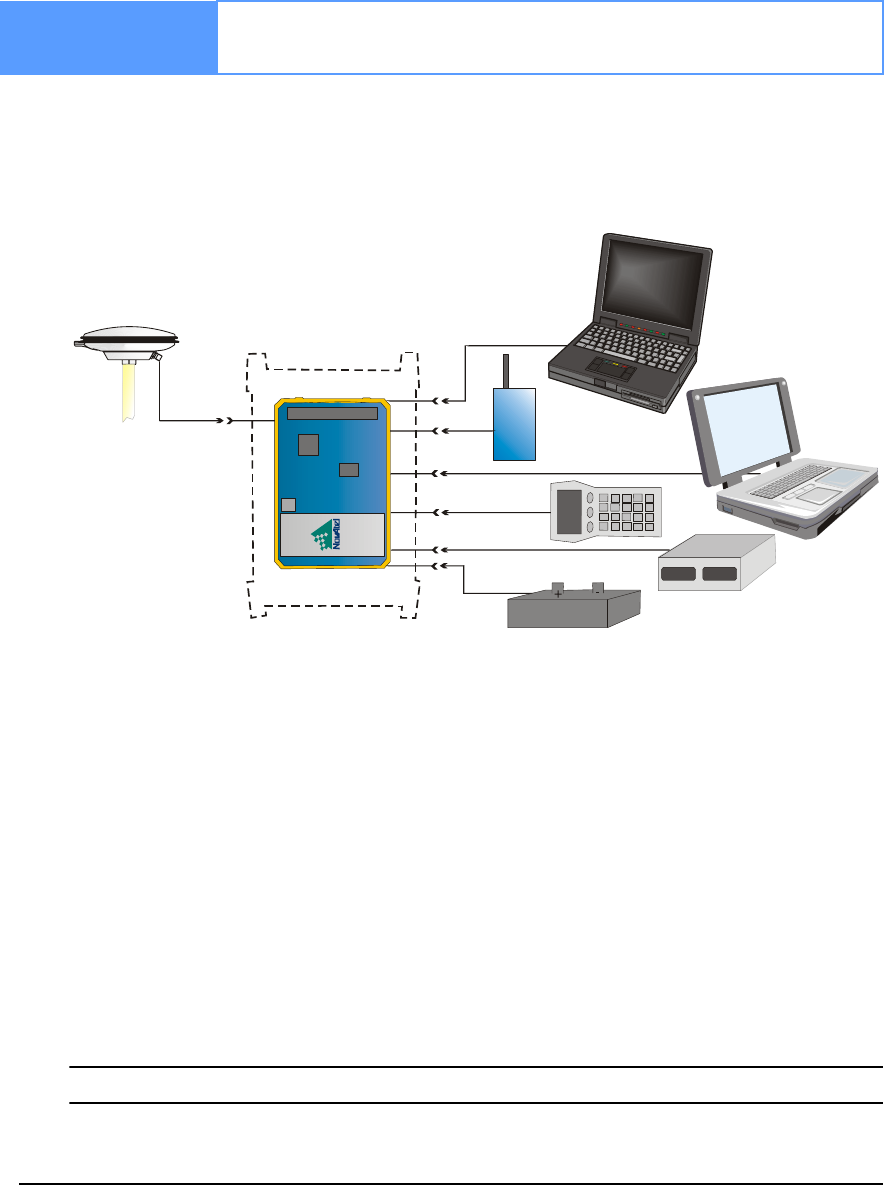
56 OEMV Family Installation and Operation User Manual Rev 5B
Chapter 4 Operation
Before operating the receiver for the first time, please ensure that you have followed the installation
instructions in Chapter 3, Installation and Set Up on Page 33. The following instructions are based on
a configuration such as that shown in Figure 15 below. It is assumed that a personal computer is used
during the initial operation and testing for greater ease and versatility.
Figure 15: Typical Operational Configuration
Reference Description Reference Description
1 OEMV Card 10 Power Input
2 OEM Enclosure 11 User-Supplied Base Radio
3 NovAtel GNSS Antenna 12 Data Logger or Rover
4 GPS Signal (RF Cable) 13 External DC Power Source
5 COM1 Link 14 Laptop or PC with NovAtel
6 COM2 Link USB drivers installed
7 USB Link 15 External Oscillator
8 COM3 Link 16 PC or Base Station
9 External Oscillator Signal
See also Figure 16 on Page 60 for a base/rover example.
1
2
3
4
5
6
7
8
9
12
14
15
16
10
11
13
Operation Chapter 4
OEMV Family Installation and Operation User Manual Rev 5B 57
4.1 Communications with the Receiver
Communication with the receiver typically consists of issuing commands through the communication
ports from an external serial communications device. This could be either a terminal or an IBM-
compatible PC that is directly connected to the receiver serial port using a null modem cable. If you
are using an RTK radio it connects to the receiver’s COM port by means of the radio serial cable
supplied with the receiver. It is recommended that you become thoroughly familiar with the
commands and logs detailed in the OEMV Firmware Reference Manual to ensure maximum
utilization of the receiver’s capabilities.
4.1.1 Serial Port Default Settings
The receiver communicates with your PC or terminal via a serial port. For communication to occur,
both the receiver and the operator interface have to be configured properly. The receiver’s COM1,
COM2 and COM3 default port settings are as follows:
• 9600 bps, no parity, 8 data bits, 1 stop bit, no handshaking, echo off
Changing the default settings requires using the COM command.
The data transfer rate you choose determines how fast information is transmitted. Take for example a
log whose message byte count is 96. The default port settings allows 10 bits/byte (8 data bits + 1 stop
bit + 1 framing bit). It therefore takes 960 bits per message. To get 10 messages per second then
requires 9600 bps. Please also remember that even if you set the bps to 9600 the actual data transfer
rate is lower and depends on the number of satellites being tracked, data filters in use, and idle time. It
is therefore suggested that you leave yourself a margin when choosing a data rate (57600 is
recommended for most applications).
CAUTION: Although the receiver can operate at data transfer rates as low as 300 bps, this is
not desirable. For example, if several data logs are active (that is, a significant amount of information
needs to be transmitted every second) but the bit rate is set too low, data will overflow the serial port
buffers, cause an error condition in the receiver status and result in lost data.
4.1.2 Communicating Using a Remote Terminal
One method of communicating with the receiver is through a remote terminal. The receiver has been
pre-wired to allow proper RS-232 interface with your data terminal. To communicate with the
terminal the receiver only requires the RX, TX, and GND lines to be used. Handshaking is not
required, although it can optionally be used. Ensure the terminal’s communications set-up matches the
receiver’s RS-232 protocol. In the case of the DL-V3, Bluetooth (default) and Ethernet are available.
4.1.3 Communicating Using a Personal Computer
An IBM-compatible PC can be set up to emulate a remote terminal as well as provide the added
flexibility of creating multiple-command batch files and data logging storage files. Any standard
communications software package that emulates a terminal can be used to establish bidirectional
communications with the receiver, for example, Hyperterminal or our own graphic user interface
(GUI) program, CDU. All data is sent as raw 8-bit binary or ASCII characters.
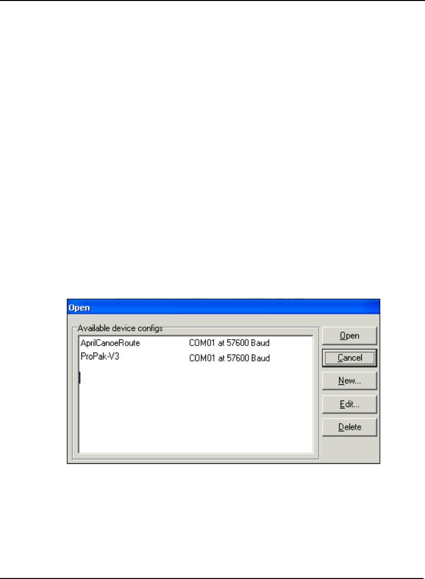
58 OEMV Family Installation and Operation User Manual Rev 5B
Chapter 4 Operation
4.2 Getting Started
Included with your receiver are NovAtel’s CDU and Convert programs. CDU is a windows-based
GUI which allows you to access the receiver's many features without the need for communications
protocol or to write special software. The Convert utility is a windows-based utility that allows you to
convert between file formats, and strips unwanted records for data file compilation. See Chapter 6,
PC Software and Firmware on Page 99 for more information on these programs and their installation.
4.2.1 Starting the Receiver
The receiver’s software resides in flash memory. When first powered, it undergoes a complete self-
test. If an error condition is detected during a self-test, the self-test status word changes. This self-test
status word can be viewed in the header of any data output log. Refer to the chapter on Messages in
the OEMV Firmware Reference Manual for header information. If a persistent error develops, please
contact your local NovAtel dealer first. If the problem is still unresolved, please contact NovAtel
directly through any of the methods in the Customer Service section at the beginning of this manual
on Page 18.
4.2.2 Communicating with the Receiver Using CDU
Launch the CDU program and select Device | Open from its main menu. The Open Configuration
window appears. The example below shows an Open Configuration window with two possible
configurations already set up. Your configurations may be different or you may have none at all, in
which case, the Open Configuration window is empty.
Refer to CDU’s Help file by selecting the Help | Contents menu. See also Chapter 6, PC Software and
Firmware starting on Page 99 for descriptions of the CDU windows available from the View menu.
Ensure you can see the Console and ASCII Messages windows by selecting them from the View menu.
When the receiver is first turned on, no data is transmitted from the COM ports except for the port
prompt. The Console window displays a port name:
[COM1] if connected to COM1 port,
[COM2] if connected to COM2 port,

Operation Chapter 4
OEMV Family Installation and Operation User Manual Rev 5B 59
or
[COM3] if connected to COM3 port
Any of the above prompts indicate that the receiver is ready and waiting for command input. The
screen may display other port names for other port types, for example USB1, USB2, USB3 or AUX.
1. You may also have to wait for output from receiver self tests. For example, on start-up,
the OEMV family receiver is set to log the RXSTATUSEVENTA log ONNEW on all
ports. See Section 7.4, RXSTATUSEVENT Log on Page 119 for more details.
2. If you find that CDU is unable to locate your OEMV family receiver, it may be that you
have previously used the SAVECONFIG command. In this case, try using a different
COM port to communicate to the receiver. Once communication has been established,
issue a FRESET STANDARD command. You should now be able to use your original
communication port again.
3. XCOM1, XCOM2 and XCOM3 virtual ports can be generated by the receiver. However they
are unlikely to appear as a port prompt as you cannot connect to these types of ports using
CDU. Also, they are not available with the COM command but may be used with other
commands, such as INTERFACEMODE and LOG. Refer to the OEMV Firmware Reference
Manual for the virtual ports available and details on the above mentioned logs.
Commands are typed at the interfacing computing device’s keypad or keyboard, and executed after
issuing a carriage return command which is usually the same as pressing the <Enter> key.
An example of a response to an input command is the FIX POSITION command. It can be as:
[COM2] fix position 51.11635 -114.0383 1048.2 [carriage return]
<OK
where [COM2] is the port prompt, followed by the command you enter from your keypad or keyboard
and [carriage return] indicates that you should press the <Enter> key.
The above example illustrates command input to the base receiver’s COM2 port which sets the
position of the base station receiver for differential operation. Confirmation that the command was
actually accepted is the appearance of <OK.
If a command is entered incorrectly, the receiver responds with:
<INVALID MESSAGE ID (or a more detailed message)
WARNING!: Ensure the Control Panel’s Power Settings on your PC are not set to go into
Hibernate or Standby modes. Data will be lost if one of these modes occurs
during a logging session.
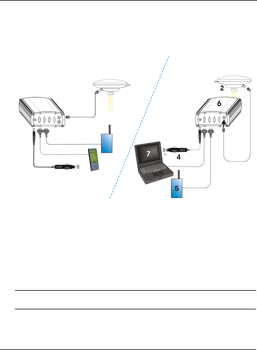
60 OEMV Family Installation and Operation User Manual Rev 5B
Chapter 4 Operation
4.3 Transmitting and Receiving Corrections
Corrections can be transmitted from a base station to a rover station to improve position accuracy. The
base station is the GNSS receiver which is acting as the stationary reference. It has a known position
and transmits correction messages to the rover station. The rover station is the GNSS receiver which
does not know its exact position and can be sent correction messages from a base station to calculate
differential GNSS positions. An example of a differential setup is given in Figure 16 below:
Figure 16: Basic Differential Setup
Reference Description
1 A ProPak-V3 receiver for the rover station
2 NovAtel GNSS antenna
3 User-supplied data storage device to COM1
4 User-supplied power supply
5 User-supplied radio device to COM2
6 A ProPak-V3 receiver for the base station
7 User-supplied laptop/PC, for setting up and monitoring, to COM1
See also Appendix C, Ethernet Configuration starting on Page 189 for the Bluetooth (default)
and Ethernet configuration options.
Errors can be introduced by system biases, as described in Section 5.1.1, GPS System Errors on Page
77. In most cases you need to provide a data link between the base station and rover station (two
NovAtel receivers) in order to receive corrections. SBAS and L-Band corrections can be
accomplished with one receiver and are exceptions to the base/rover concept. Generally a link capable
1
12V
2
4
Base
Rover
5
3

Operation Chapter 4
OEMV Family Installation and Operation User Manual Rev 5B 61
of data throughput at a rate of 9600 bits per second, and less than 4.0 s latency, is recommended.
Once your base and rover are set up, you can configure them as shown in the configuration examples
that follow in Sections 4.3.1 - 4.3.2 starting on Page 62.
4.3.1 Base Station Configuration
At the base station, enter the following commands:
interfacemode port rx_type tx_type [responses]
fix position latitude longitude height
log port message [trigger [period]]
For example:
RTCA interfacemode com2 none rtca off
fix position 51.11358042 -114.04358013 1059.4105
log com2 rtcaobs ontime 1
log com2 rtcaref ontime 10
log com2 rtca1 ontime 5
log com2 rtcaephem ontime 10 1 (optional)
RTCM interfacemode com2 none rtcm off
fix position 51.11358042 -114.04358013 1059.4105
log com2 rtcm3 ontime 10
log com2 rtcm22 ontime 10 1
log com2 rtcm1819 ontime 1
log com2 rtcm1 ontime 5
RTCMV3 interfacemode com2 none rtcmv3 off
fix position 51.11358042 -114.04358013 1059.4105
log com2 rtcm1006 ontime 10
log com2 rtcm1003 ontime 1
CMR+ interfacemode com2 none cmr off
fix position 51.11358042 -114.04358013 1059.4105
log com2 cmrobs ontime 1
log com2 cmrplus ontime 1 (important to use ontime 1 with cmrplus)
CMR interfacemode com2 none cmr off
fix position 51.11358042 -114.04358013 1059.4105

62 OEMV Family Installation and Operation User Manual Rev 5B
Chapter 4 Operation
log com2 cmrobs ontime 1
log com2 cmrref ontime 10
log com2 cmrdesc ontime 10 1
4.3.2 Rover Station Configuration
At the rover station, enter:
interfacemode port rx_type tx_type [responses]
For example:
RTCA interfacemode com2 rtca none off
RTCM interfacemode com2 rtcm none off
RTCMV3 interfacemode com2 rtcmv3 none off
CMR+ interfacemode com2 cmr none off
CMR interfacemode com2 cmr none off (same as CMR+)
4.3.3 Configuration Notes
For compatibility with other GNSS receivers, and to minimize message size, it is recommended that
you use the standard form of RTCA, RTCM, RTCMV3 or CMR corrections as shown in the base and
rover examples above. This requires using the INTERFACEMODE command to dedicate one
direction of a serial port to only that message type. When the INTERFACEMODE command is used
to change the mode from the default, NOVATEL, you can no longer use NovAtel format messages.
If you wish to mix NovAtel format messages and RTCA, RTCM, RTCMV3 or CMR messages on the
same port, you can leave the INTERFACEMODE set to NOVATEL and log out variants of the
standard correction messages with a NovAtel header. ASCII or binary variants can be requested by
simply appending an "A" or "B" to the standard message name. For example on the base station:
interfacemode com2 novatel novatel
fix position 51.11358042 -114.04358013 1059.4105
log com2 rtcm1b ontime 2
Using the receiver in this mode consumes more CPU bandwidth than using the native
differential messages as shown in Section 4.3.1, Base Station Configuration on Page 61.
At the rover station you can leave the INTERFACEMODE default settings (interfacemode com2
novatel novatel). The rover receiver recognizes the default and uses the corrections it receives with a
NovAtel header.
The PSRDIFFSOURCE and RTKSOURCE commands set the station ID values which identify the
base stations from which to accept pseudorange or RTK corrections respectively. They are useful

Operation Chapter 4
OEMV Family Installation and Operation User Manual Rev 5B 63
commands when the rover station is receiving corrections from multiple base stations. See Section
5.2, Satellite-Based Augmentation System (SBAS) on Page 78 for more information on SBAS.
All PSRDIFFSOURCE entries fall back to SBAS (even NONE) for backwards compatibility.
At the base station it is also possible to log out the contents of the standard corrections in a form that is
easier to read or process. These larger variants have the correction fields broken out into standard
types within the log, rather than compressed into bit fields. This can be useful if you wish to modify
the format of the corrections for a non-standard application, or if you wish to look at the corrections
for system debugging purposes. These variants have "DATA" as part of their names (for example,
RTCADATA1, RTCMDATA1, CMRDATAOBS, and more). Refer also to the OEMV Firmware
Reference Manual, which describes the various message formats in more detail.
4.4 Using the DL-V3
A group is a set of logs for the receiver. The default software configuration for group information
includes a group named default. A powerup group must be created to take advantage of the automatic
functionality. Refer to the DL-V3 Firmware Reference Manual for more information on groups,
commands and logs specific to the DL-V3.
Upon acquisition of coarse time, if a group named powerup exists, the DL-V3 executes the group
automatically.
The FRESET command allows you to reset the DL-V3 to its factory default settings. SITEDEF logs,
refer to the DL-V3 Firmware Reference Manual, contain site record information. For example:
#SITEDEFA,COM1,0,61.0,FINESTEERING,1420,316947.028,00180020,e40c,2678;
0,"","DL-V3ii",0,0.000000000,"",1420,1420,316890.000,316935.000,00000000,0
*c56c1a5d
4.4.1 Log Data from a Site to a File
Consider the case when you want to log data at a site and append a filename and other information.
The following steps apply to a base or rover site. For the base, you only need to log one file per
session.
There is no need to continually start and stop logging if you are using post-processing
software, where it is dealt with automatically.
To log a group and update the site information
1. Select the Group
2. Edit the Site
3. Start the Data Logging
4. Stop the Data Logging

64 OEMV Family Installation and Operation User Manual Rev 5B
Chapter 4 Operation
1. Select the Group
Ensure your antenna is in the correct position on the base or rover.
DLVTool is available from our website at: http:// www.novatel.com/support/fwswupdates.htm.
The the DL-V3 captures sets of logs using log groups. You create a group in DLVTool and then upload
the group to the DL-V3.
Launch DLVTool from the Start menu folder specified during the installation process. The default
location is Start | Programs | NovAtel OEMV | DLVTool. Select the Group Editor button. Check the
logs in the group that you want to log to the DL-V3. Ensure the logs you want to send to the CF card
are shown as File in the Log To column of the Group Editor dialog’s Logs tab. If necessary, use the
Edit button to change the Log To field value. Click OK in the Edit Log dialog, if open, and return to
the Group Editor dialog.
2. Edit the Site
In the Group Editor dialog, select a group from the Group Name drop-down list, and select the Site
tab. Check the Automatically Log Site on Startup and the Include Site Information checkboxes. Then
enter a site name or number, and the height of the antenna ‘lip’ from the site you are measuring.
Place the tape measure from the lip to where the tip of the antenna pole touches the
ground (do not measure straight down). The slant from the edge of the antenna is
different than when the measurement is straight down.
Add 33 mm to the measured reading. This makes up for the distance of the antenna
element to the lip on NovAtel 700-series antennas.
Click OK for your input to take effect and return you to the main DLVTool window.
You can now log a site and the site information is written to the log file.
3. Start the Data Logging
Select the UpLoad button. Once connected, select the group to upload to the DL-V3 from the list of
groups on the PC: panel of the Upload dialog. Select the UpLoad to DLV button to copy the group to
the DL-V3.
Repeat these steps to upload more log groups. Up to 5 log groups can be stored in the DL-V3 at once.
Select a log group in the DLV: panel of the Upload dialog and click Start to activate it. You are now
logging a new site.
4. Stop the Data Logging
In the Upload dialog, click on the Stop button to stop logging data. Once the data logging has stopped,
it is no longer writing to the card. While you move the antenna, the receiver is still functioning but it is
not logging data. To start a new site at a new location, repeat steps #1 to #4. Information is appended
to the CF card file.

Operation Chapter 4
OEMV Family Installation and Operation User Manual Rev 5B 65
4.5 Enabling SBAS Positioning
All OEMV family receivers are capable of SBAS positioning. This positioning mode is enabled using
the SBASCONTROL command. EGNOS at one time used the IGNOREZERO test mode. At the time
of printing, ZEROTOTWO is the correct setting for all SBAS, including EGNOS, running in test
mode. On a simulator, you may want to leave this parameter off or specify NONE explicitly. As a
result, the following commands are typically used to enable WAAS and other SBAS modes, for
example EGNOS, respectively:
sbascontrol enable waas
sbascontrol enable egnos 0 zerototwo
See Section 5.2, Satellite-Based Augmentation System (SBAS) on Page 78 for more information.
4.6 Enabling L-Band (OEMV-1, OEMV-1G, OEMV-3, DL-V3 & ProPak-V3)
L-Band equipped receivers allow you to achieve sub-meter accuracy. In order to use this positioning
mode, you must enable L-band tracking to the Canada-Wide Differential Global Positioning System
(CDGPS) or OmniSTAR signal. A subscription to OmniSTAR is required to use the OmniSTAR
service. The CDGPS signal is free and available without subscription (a CDGPS coverage map is
shown in Figure 28 on Page 87).
To obtain an OmniSTAR subscription, contact OmniSTAR at 1-800-338-9178 or 713-785-5850. If
you contact OmniSTAR, you will be asked to provide the receiver’s OmniSTAR serial number (which
is different from the NovAtel serial number). To obtain the OmniSTAR serial number, enter the
following command in a terminal window or the Console window in CDU:
log lbandinfo
The log that is generated displays the L-Band serial number in the fifth field following the log header.
It is a six digit number in the range 700000 to 799999. This log also provides the status of your
subscription. Refer to the LBANDINFO command for more information.
In order to activate an OmniSTAR subscription, the receiver must be powered and tracking an L-Band
satellite. When advised by OmniSTAR of the appropriate satellite frequency and data link rate for
your location, use the ASSIGNLBAND command to configure your receiver. The CDGPS frequencies
are on Page 86 and these can also be used with the ASSIGNLBAND command. Below are examples
for using either CDGPS and OmniSTAR:
assignlband cdgps 1547547 4800
assignlband omnistar 1536782 1200
1. In addition to a NovAtel receiver with L-Band capability, a subscription to the
OmniSTAR, or use of the free CDGPS, service is required. Contact NovAtel for details.
2. The frequency assignment can be made in Hz or kHz. For example:
Hz: assignlband omnistar 1536782000 1200
kHz: assignlband omnistar 1536782 1200
A value entered in Hz is rounded to the nearest 500 Hz.

66 OEMV Family Installation and Operation User Manual Rev 5B
Chapter 4 Operation
To confirm you are tracking an L-Band signal, log the L-Band status information by entering the
following command:
log lbandstat
For example, if you are receiving CDGPS, the fifth field after the header should be 00c2:
lbandstat com1 0 43.5 finesteering 1295 149951.671 00000000 976f 34461
<1547546977 46.18 4541.0 0.00 00c2 00f0 0 0 0 8070 0001 0 0 0
Please refer to the LBANDSTAT command for details.
4.7 Pass-Through Logging
The pass-through logging feature enables the GNSS receiver to redirect any ASCII or binary data that
is input at a specified COM port or, if available, USB port to any specified receiver COM or USB port.
This capability, in conjunction with the SEND command, can allow the receiver to perform bi-
directional communications with other devices such as a modem, terminal, or another receiver.
There are several pass-through logs. PASSCOM1, PASSCOM2, PASSCOM3, PASSXCOM1,
PASSXCOM2, PASSXCOM3, PASSUSB1, PASSUSB2, PASSUSB3 and PASSAUX are available
on OEMV family receivers for logging through serial ports. The AUX port is available on OEMV-3-
based products.
Refer to the PASSCOMx log for details.
4.8 T Sync Option (OEV-2, OEMV-3 or ProPak-V3 only)
This section describes the relationship constraints of the input signal phase when the Time
Synchronization Modification (T Sync Mod) option has been added to an OEMV-2 card, OEMV-3
card or ProPak-V3.
The 5, or 10, MHz external oscillator and 1PPS signals must maintain a phase relationship as shown
in Figures 17 through 20 starting on Page 67. The 1PPS signal must NOT fall within 5 ns of each of
the 4 positions of the 5 MHz sine wave, or within 5 ns of each of the 2 positions of the 10 MHz sine
wave. These are areas of instability and should be avoided.
When an external oscillator is connected, T Sync pulses are sent through hardware on the receiver
card and cannot be disabled. You must issue a time-synchronization-enabling command (refer to
ADJUST1PPS TIME in the OEMV Family Firmware Reference Manual) for the receiver to track
properly.
To adjust the phase relationship of the 5, or 10, MHz and 1PPS signals, add additional RF cable to the
5, or 10, MHz line. For example, if using RG58, each 1 meter piece will move the 5, or 10, MHz phase
by approximately 5 ns.
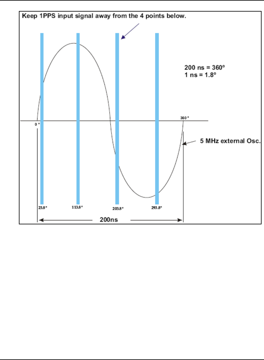
Operation Chapter 4
OEMV Family Installation and Operation User Manual Rev 5B 67
Figure 17: OEMV-3 and ProPak-V3 T Sync 5 MHz and 1PPS
(by at least 5 ns)
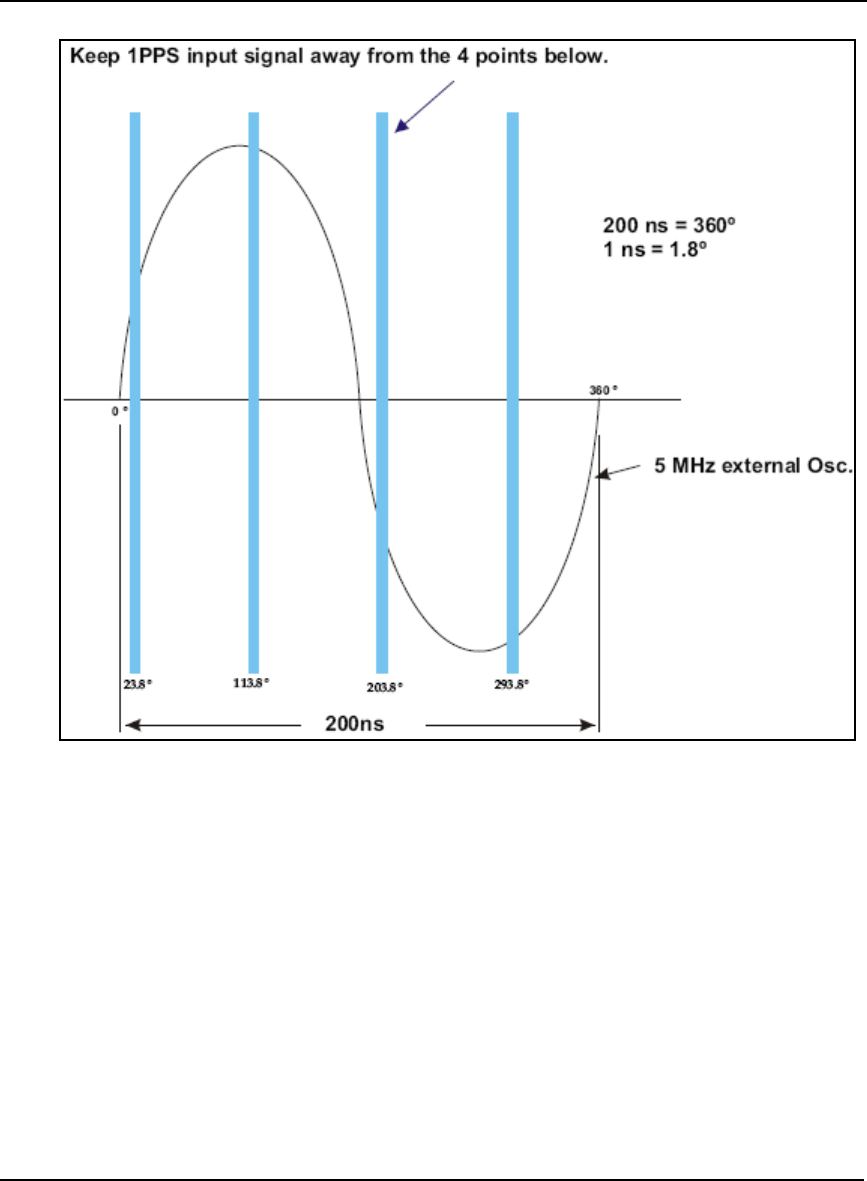
68 OEMV Family Installation and Operation User Manual Rev 5B
Chapter 4 Operation
Figure 18: FlexPak-V2 T Sync 5 MHz and 1PPS
(by at least 5 ns)
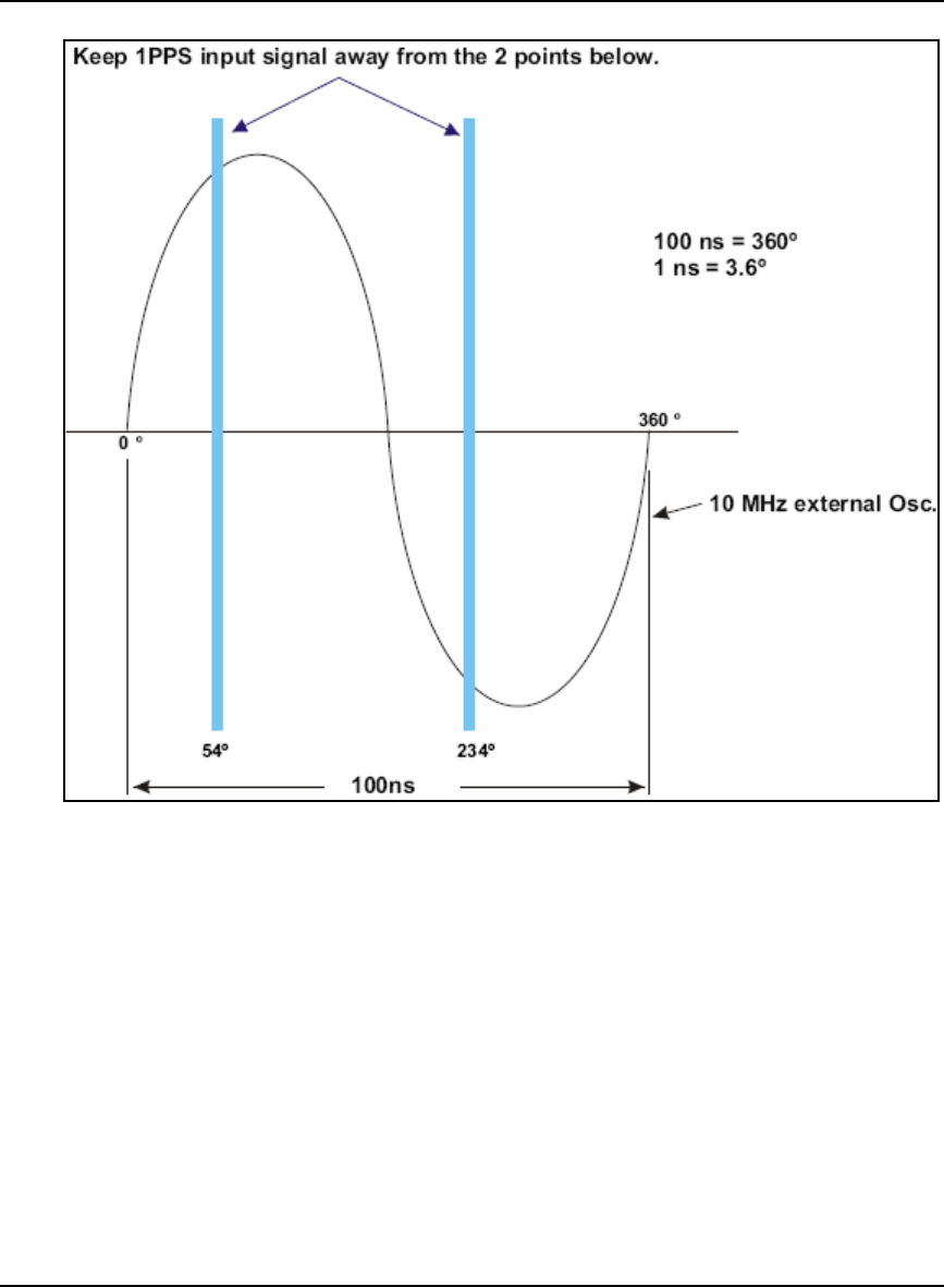
Operation Chapter 4
OEMV Family Installation and Operation User Manual Rev 5B 69
Figure 19: OEMV-3 and ProPak-V3 T Sync 10 MHz and 1PPS
(by at least 5 ns)
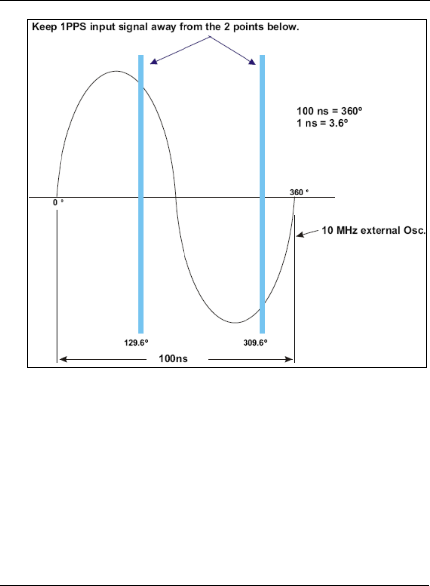
70 OEMV Family Installation and Operation User Manual Rev 5B
Chapter 4 Operation
Figure 20: FlexPak-V2 T Sync 10 MHz and 1PPS
4.9 Transferring Time Between Receivers
The ADJUST1PPS command is used to as part of the procedure to transfer time between receivers.
The number of pulses per second (PPS) is always set to 1 Hz with this command. It is typically used
when the receiver is not adjusting its own clock and is using an external reference frequency.
The TIMESYNC log is also used to synchronize time between receivers. It contains a time status field
that may show COARSE or FINE for example. For a complete list of the time status values and their
definitions, please refer to Section 1.3, GPS Time Status in the OEMV Firmware Reference Manual.
Section 4.9.3 starting on Page 72 provides details on the time transfer procedure. Definition used in
the procedure are in Section 4.9.2 starting on Page 71. Please also refer to the ADJUSTIPPS
command and the TIMESYNC log descriptions.
(by at least 5 ns)

Operation Chapter 4
OEMV Family Installation and Operation User Manual Rev 5B 71
4.9.1 GPS to Receiver Time Synchronization
Synchronization of receiver time with GPS time does not occur until the receiver locks onto its first
satellite. The GPS L1 signal has two main streams of data modulated on the carrier. These data
streams are the C/A code (1.023 MHz rate) and the P(Y) code (10.23 MHz rate). Additionally, a
navigation message (at a 50 Hz rate) contains GPS satellite data including the ephemeris, clock
corrections and constellation status. This navigation message is encoded on both the C/A and P(Y)
codes. The navigation message is transmitted via individual subframes and each subframe is 300 bits
in length. With the 50 Hz data bit rate there is a new subframe transmitted every 6 seconds.
Although GLONASS could be used for time synchronization, OEMV receivers use GPS.
4.9.2 Time Definitions
The following are related definitions:
Coarse Time Each subframe contains the transmit time of the next subframe in seconds
of GPS time of week. After the first subframe is collected and decoded by
the receiver, an approximate calculation of the "receiver clock offset" can
be made. The receiver clock offset is the difference between GPS time and
internal receiver time. The calculation is based on subframe transmit time
and the approximate propagation time from the satellite signal to the
receiver. The position of the satellite and receiver clock offset are used to
re-initialize the seconds counter on the receiver, resulting in receiver/GPS
time synchronization. The accuracy of the receiver time is expected to be
within 30 milliseconds (ms) of GPS time. This initial synchronization is
referred to as coarse time and is indicated by COARSE in the time status
field of the TIMESYNC log.
Fine Time Once at least 4 satellites have been acquired to calculate the antenna
position, a more accurate estimate of the receiver clock offset is calculated.
The new receiver clock offset is used to synchronize the receiver clock
even closer to GPS time. This is referred to as fine time and is indicated by
FINE or FINESTEERING in the time status field of the TIMESYNC log.
Fine time accuracy is a function of the GPS constellation status. For the
Standard Position Service (SPS) the time accuracy is specified as 300 ns (1
sigma) assuming that clock steering is enabled.
Fine Clock An OEMV family receiver that is tracking satellites, and has a receiver
clock state of FINE or FINESTEERING.
Cold Clock An OEMV family receiver that needs to have its clock synchronized with
the Fine receiver. It may have any clock state including UNKNOWN.
Warm Clock An OEMV family receiver that has its clock adjusted to better then 500 ms.
Refer to the TIME log to view the clock offset.

72 OEMV Family Installation and Operation User Manual Rev 5B
Chapter 4 Operation
The section that follows gives procedures for transferring time from a Fine Clock receiver to a Cold or
Warm Clock receiver.
4.9.3 Procedures to Transfer Time
These procedures are to transfer time between a Fine Clock and a Cold or Warm Clock GPS receiver.
Transfer COARSE time (<10 ms) from a Fine Clock to a Cold Clock GPS receiver
1. Connect a COM port from the Fine Clock to the Cold Clock (for example, COM2 on the
Fine Clock receiver to COM3 on the Cold Clock receiver). Configure both ports to the
same baud rate and handshaking configurations.
2. Issue this command to the Fine Clock receiver:
log com2 timesyncb ontime 1
3. Issue this command to the Cold Clock receiver:
adjust1pps time
When the Cold Clock receiver receives the TIMESYNC log, it sets its clock allowing for a 100 ms
transfer delay.
Transfer FINE time (<50 ns) from a Fine Clock to a Cold Clock GPS receiver
1. Connect a COM port from the Fine Clock to the Cold Clock receiver (for example, COM2
on the Fine Clock receiver to COM3 on the Cold Clock receiver). Configure both ports
to the same baud rate and handshaking configurations.
2. Issue this command to the Fine Clock receiver:
log com2 timesyncb ontime 1
3. Connect the 1PPS signal of the Fine Clock receiver to the mark 1 input (Event1) of the
Cold Clock receiver.
4. Issue this command to the Cold Clock receiver:
adjust1pps markwithtime
When the Cold Clock receiver receives the 1PPS event from the Fine Clock receiver, it checks to see
if it has received a valid TIMESYNC log within 200 ms of the last 1PPS event. If so, it sets the Cold
Clock receiver clock to the time of the Fine Clock receiver. See Figure 21, 1PPS Alignment on Page
73 below.
Transfer FINE time from a Fine Clock to a Warm Clock GPS receiver
1. Connect the 1PPS signal of the Fine Clock receiver to the mark 1 input (Event1) of the
Warm Clock receiver.
2. Issue this command to the Warm Clock receiver:
adjust1pps mark
Operation Chapter 4
OEMV Family Installation and Operation User Manual Rev 5B 73
The phase of the Warm Clock receiver clock is adjusted by the fractional measurement of the Fine
Clock receiver’s 1PPS mark input event. In other words, it synchronizes the Warm Clock receiver’s
1PPS to the incoming 1PPS of the Fine Clock receiver. It does NOT adjust the 1 second Time of Week
(TOW) counter or the receiver's Week Number. This procedure is used to make small corrections to
the Warm Clock receiver’s clock.
Figure 21: 1PPS Alignment
1PPS IN
(1 ms)
TIME
S
YN
C
log,
transmit time
dependant
on baud rate
RS232
TTL
Fine Clock
Receiver
Connected to
COM Input
On Warm
Clock Receiver
1PPS on
Fine Clock
Receiver
Connected
to MK1I on
Warm Clock
Receiver
The next
TIMESYNC
log is
triggered
by the
next PPS
10 ms

74 OEMV Family Installation and Operation User Manual Rev 5B
Chapter 5 Positioning Modes of Operation
NovAtel's dual frequency GNSS receivers have several important performance advantages depending
on your positioning requirements. Dual frequency allows direct measurement of the signal delay
through the ionosphere and is critical to fast and reliable integer ambiguity resolution when
positioning using carrier measurements.
Dual frequency can improve the performance of DGPS, SBAS, and RTK positioning. Using RTCM
type 15 messages allows the DGPS user to apply a local ionospheric correction to their dual frequency
receiver to improve code positioning performance on larger baselines (hundreds of km). SBAS
positioning is improved by applying a local correction instead of using the SBAS ionospheric grid,
and RTK solutions are improved on long baselines by using an ionosphere free solution.
By default the OEMV-1, OEMV-1G, OEMV-3, DL-V3 and ProPak-V3 models with L-Band software
support the standard Canada-Wide Differential Global Positioning System (CDGPS) sub-meter L1/L2
service and the OmniSTAR Virtual Base Station (VBS) sub-meter L1 service. The OmniSTAR VBS
service is upgradeable on the OEMV-3, DL-V3 and ProPak-V3 to the Extra Performance (XP)
decimeter L1/L2 service or High Performance (HP) sub-decimeter L1/L2 service. Refer also to the
AUTH command in the OEMV Firmware Reference Manual.
The OEMV family of receivers operate in the most accurate positioning mode possible with the
signals available, and immediately drop to the next positioning mode if the current signal times out.
The following single and dual frequency modes of operation are described further in this chapter:
• Single Point
• Satellite-Based Augmentation System (SBAS)
• Pseudorange Differential
• L-Band
• Carrier-Phase Differential
Refer to the GPS Overview section of the GPS+ Reference Manual for an overview of GPS
positioning.
5.1 Single-Point
The NovAtel OEMV family receivers are capable of absolute 3-D single-point positioning accuracies
of 1.8 meters Root Mean Square (RMS1) (GDOP < 2; no multipath).
The general level of accuracy available from single-point operation may be suitable for many types of
positioning such as ocean going vessels, general aviation, and recreational vessels that do not require
position accuracies of better than 1.8 meters RMS. However, increasingly more and more applications
desire and require a much higher degree of accuracy and position confidence than is possible with
single-point pseudorange positioning. This is where differential GPS (DGPS) plays a dominant role in
higher accuracy real-time positioning systems (see the following sections of this chapter).
1. RMS: Root Mean Square (a probability level of 68%)

Positioning Modes of Operation Chapter 5
OEMV Family Installation and Operation User Manual Rev 5B 75
By averaging many GPS measurement epochs over several hours, it is possible to achieve a more
accurate absolute position. This section attempts to explain how the position averaging function
operates and to provide an indication of the level of accuracy that can be expected versus total
averaging time.
The POSAVE command implements position averaging for base stations. Position averaging
continues for a specified number of hours or until the averaged position is within specified accuracy
limits. Averaging stops when the time limit or the horizontal standard deviation limit or the vertical
standard deviation limit is achieved. When averaging is complete, the FIX POSITION command is
automatically invoked.
If the maximum time is set to 1 hour or larger, positions are averaged every 10 minutes and the
standard deviations reported in the AVEPOS log should be correct. If the maximum time is set to less
than 1 hour, positions are averaged once per minute and the standard deviations reported in the log are
not likely to be accurate; also, the optional horizontal and vertical standard deviation limits cannot be
used.
If the maximum time that positions are to be measured is set to 24 hours, for example, you can then
log AVEPOS with the trigger ‘onchanged’ to see the averaging status:
posave 24
log com1 avepos onchanged
If desired, you could initiate differential logging, then issue the POSAVE command followed by the
SAVECONFIG command. This would cause the receiver to average positions after every power-on or
reset, then invoke the FIX POSITION command to enable it to send differential corrections.
The position accuracy that may be achieved by these methods depends on many factors: average
satellite geometry, sky visibility at antenna location, satellite health, time of day, and so on. The
following graph summarizes the results of several examples of position averaging over different time
periods. The intent is to provide an idea of the relationship between averaging time and position
accuracy. All experiments were performed using a dual frequency receiver with an ideal antenna
location, see Figure 22, Single-Point Averaging (Typical Results) on Page 76. Figure 23 on Page 76
shows the results from the same dual frequency receiver but with WAAS corrections available.
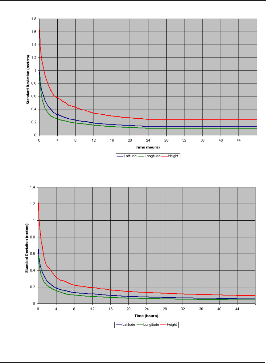
76 OEMV Family Installation and Operation User Manual Rev 5B
Chapter 5 Positioning Modes of Operation
Figure 22: Single-Point Averaging (Typical Results)
Figure 23: Single-Point Averaging (Typical Results with WAAS)

Positioning Modes of Operation Chapter 5
OEMV Family Installation and Operation User Manual Rev 5B 77
The position averaging function is useful for obtaining the WGS84 position of a point to a reasonable
accuracy without having to implement differential GPS. It is interesting to note that even a six hour
occupation can improve single-point GPS accuracy from over 1.5 meters to better than a meter. This
improved accuracy is primarily due to the reductions of the multipath errors in the GPS signal.
Again, it is necessary to keep in mind that the resulting standard deviations of the position averaging
can vary quite a bit, but improve over longer averaging times. To illustrate, the position averaging
function was run for a period of 40 hours. The resulting standard deviation in latitude varied from
0.152 to 1.5589 meters. Similarly, the variation in longitude and height were 0.117 to 0.819 meters
and 0.275 to 2.71 meters respectively. This degree of variation becomes larger for averaging periods
of less than 12 hours due to changes in the satellite constellation. The graph provides some indication
of the accuracy one may expect from single-point position averaging.
The next section deals with the type of GPS system errors that can affect accuracy in single-point
operation.
5.1.1 GPS System Errors
In general, GPS SPS C/A code single-point pseudorange positioning systems are capable of absolute
position accuracies of about 1.8 meters or less. This level of accuracy is really only an estimation, and
may vary widely depending on numerous GPS system biases, environmental conditions, as well as the
GPS receiver design and engineering quality.
There are numerous factors which influence the single-point position accuracies of any GPS C/A code
receiving system. As the following list shows, a receiver’s performance can vary widely when under
the influences of these combined system and environmental biases.
•Ionospheric Group Delays The earth’s ionospheric layers cause varying degrees of
GPS signal propagation delay. Ionization levels tend to
be highest during daylight hours causing propagation
delay errors of up to 30 meters, whereas night time
levels are much lower and may be as low as 6 meters.
•Tropospheric Refraction Delays The earth’s tropospheric layer causes GPS signal
propagation delays. The amount of delay is at the
minimum (about three metres) for satellite signals
arriving from 90 degrees above the horizon (overhead),
and progressively increases as the angle above the
horizon is reduced to zero where delay errors may be as
much as 50 metres at the horizon.
•Ephemeris Errors Some degree of error always exists between the
broadcast ephemeris’ predicted satellite position and the
actual orbit position of the satellites. These errors
directly affect the accuracy of the range measurement.
•Satellite Clock Errors Some degree of error also exists between the actual
satellite clock time and the clock time predicted by the
broadcast data. This broadcast time error causes some
bias to the pseudorange measurements.
•Receiver Clock Errors Receiver clock error is the time difference between GPS
receiver time and true GPS time. All GPS receivers have
differing clock offsets from GPS time that vary from
receiver to receiver by an unknown amount depending
on the oscillator type and quality (TCXO versus OCXO,

78 OEMV Family Installation and Operation User Manual Rev 5B
Chapter 5 Positioning Modes of Operation
and so on). However, because a receiver makes all of its
single-point pseudorange measurements using the same
common clock oscillator, all measurements are equally
offset, and this offset can generally be modeled or quite
accurately estimated to effectively cancel the receiver
clock offset bias. Thus, in single-point positioning,
receiver clock offset is not a significant problem.
•Multipath Signal Reception Multipath signal reception can potentially cause large
pseudorange and carrier phase measurement biases.
Multipath conditions are very much a function of
specific antenna site location versus local geography and
man-made structural influences. Severe multipath
conditions could skew range measurements by as much
as 100 meters or more. Refer to the Multipath section of
the GPS+ Reference Manual for more information.
5.2 Satellite-Based Augmentation System (SBAS)
A Satellite-Based Augmentation System (SBAS) is a type of geo-stationary satellite system that
improves the accuracy, integrity, and availability of the basic GPS signals. Accuracy is enhanced
through the use of wide area corrections for GPS satellite orbits and ionospheric errors. Integrity is
enhanced by the SBAS network quickly detecting satellite signal errors and sending alerts to receivers
to not use the failed satellite. Availability is improved by providing an additional ranging signal to
each SBAS geostationary satellite.
SBAS includes the Wide-Area Augmentation System (WAAS), the European Geo-Stationary
Navigation System (EGNOS), and the MTSAT Satellite-Based Augmentation System (MSAS). The
Chinese SNAS and Indian GAGAN systems are also planned. At the time of publication, there are
three WAAS satellites over the Pacific Ocean (PRN 122, PRN 134 and PRN 135), an EGNOS satellite
over the eastern Atlantic Ocean (PRN 120) and another EGNOS GEO satellite over the African mid-
continent (PRN 124). SBAS data is available from any of these satellites and more satellites will be
available in the future.
Since July, 2003, WAAS has been certified for Class 1/ Class 2 civilian aircraft navigation.
Figure 24, SBAS and NovAtel 2006 on Page 79 shows the regions applicable to each SBAS system
mentioned in the paragraph above and how NovAtel is involved in each of them.
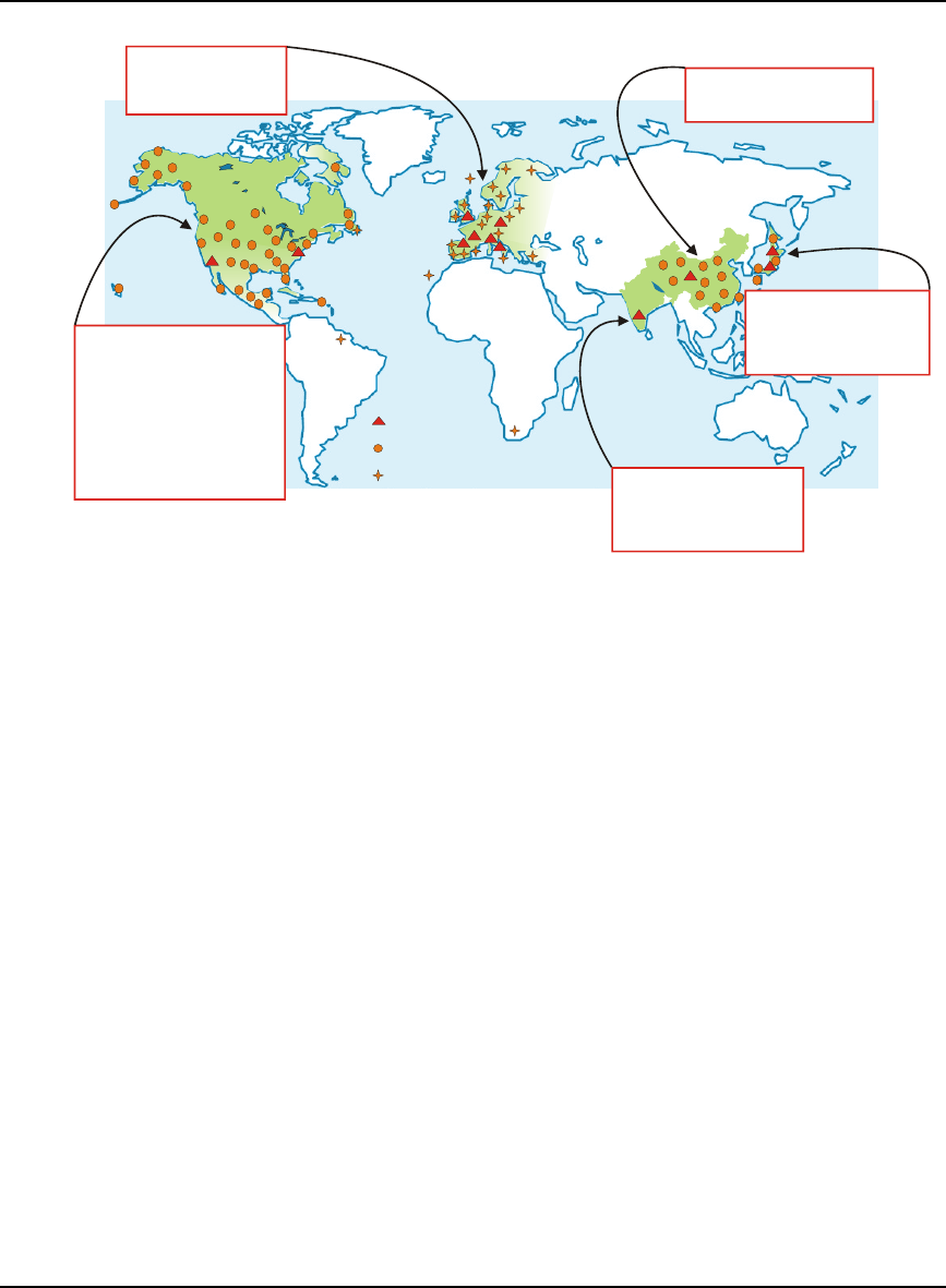
Positioning Modes of Operation Chapter 5
OEMV Family Installation and Operation User Manual Rev 5B 79
Figure 24: SBAS and NovAtel 2006
SBAS is made up of a series of Reference Stations, Master Stations, Ground Uplink Stations and
Geostationary Satellites (GEOs), see Figure 25 on Page 80. The Reference Stations, which are
geographically distributed, pick up GPS satellite data and route it to the Master Stations where wide
area corrections are generated. These corrections are sent to the Ground Uplink Stations which up-link
them to the GEOs for re-transmission on the GPS L1 frequency. These GEOs transmit signals which
carry accuracy and integrity messages, and which also provide additional ranging signals for added
availability, continuity and accuracy. These GEO signals are available over a wide area and can be
received and processed by OEMV family GPS receivers with appropriate firmware. GPS user
receivers are thus able to receive SBAS data in-band and use not only differential corrections, but also
integrity, residual errors and ionospheric information for each monitored satellite.
The signal broadcast via the SBAS GEOs to the SBAS users is designed to minimize modifications to
standard GPS receivers. As such, the GPS L1 frequency (1575.42 MHz) is used, together with GPS-
type modulation - for example, a Coarse/Acquisition (C/A) pseudorandom (PRN) code. In addition,
the code phase timing is maintained close to GPS time to provide a ranging capability.
The primary functions of SBAS include:
• data collection
• determining ionospheric corrections
• determining satellite orbits
• determining satellite clock corrections
• determining satellite integrity
• independent data verification
• SBAS message broadcast and ranging
• system operations and maintenance
WAAS:
USA (1996-1999) 1st Generation
WAAS G-II Receivers
Technology Refresh (2004-2006)
Geostationary Command &
Control Segment (2004-2006)
•
•
•
•
•
148 WRS receivers
21 GUS receivers
160 WAAS G-II receivers
13 L1/L5 Signal Generators
15 L1/L5 GUS receivers
EGNOS:
Europe
(2001-2002)
•
24 RIMS-C receivers
(Integrity Channel)
MSAS:
Japan
6 NLES GUS receivers
4 UPC receivers
(1998-2003)
•
47 MSAS WRS receivers
•
•
SNAS
China
(2000-2002)
•
73 WAAS WRS receivers
GAGAN:
India
3 L1/L5 GUS receivers
3 L1/L5 Signal Generators
(2005)
•
•
18 WAAS-G2 receivers
•
Key
Wide Area Master
Station
Wide Area Reference
or Earth Station
EGNOS RIMS Site
SBAS and NovAtel Worldwide
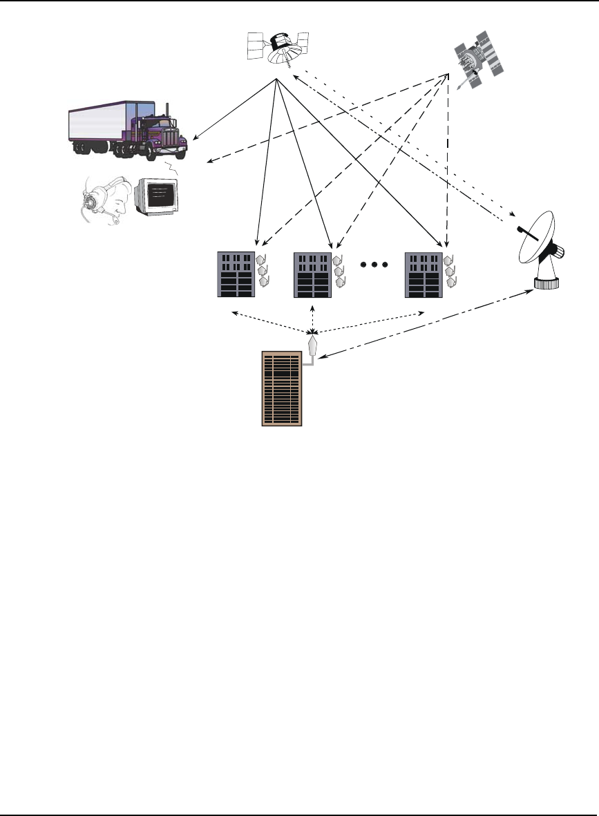
80 OEMV Family Installation and Operation User Manual Rev 5B
Chapter 5 Positioning Modes of Operation
Figure 25: The SBAS Concept
Reference Description Reference Description
1 Geostationary Satellite (GEO) 8 C-Band
2 GPS Satellite Constellation 9 SBAS Reference Station
3 L1 10 SBAS Master Station
4 L1 and C-Band 11 Ground Uplink Station
5 L1 and L2
6GPS User
7 Integrity data, differential
corrections and ranging control
5.2.1 SBAS Receiver
All models of NovAtel OEMV receivers are equipped with SBAS capability. The ability to
incorporate the SBAS corrections into the position is available in these models.
SBAS data can be output in log format (RAWWAASFRAMEA/B, WAAS0A/B-WAAS27A/B), and
can incorporate these corrections to generate differential-quality position solutions. Standard SBAS
data messages are analyzed based on RTCA standards for GPS/WAAS airborne equipment.
An SBAS-capable receiver permits anyone within the area of coverage to take advantage of its
12
345
6
7
8
9
99
10
11
7

Positioning Modes of Operation Chapter 5
OEMV Family Installation and Operation User Manual Rev 5B 81
benefits with no subscription fee.
5.2.2 SBAS Commands and Logs
The command SBASCONTROL, enables the use of the SBAS corrections in the position filter. In
order to use this command, first ensure that your receiver is capable of receiving SBAS corrections.
Several SBAS specific logs also exist and are all prefixed by the word WAAS except for the
RAWWAASFRAME log.
The PSRDIFFSOURCE command sets the station ID value which identifies the base station from
which to accept pseudorange corrections. All DGPS types may revert to SBAS, if enabled using the
SBASCONTROL command.
Refer to the OEMV Family Firmware Reference Manual for more details on the SBAS commands and
logs mentioned above.
5.3 Pseudorange Differential
There are two types of differential positioning algorithms: pseudorange and carrier phase. In both of
these approaches, the “quality” of the positioning solution generally increases with the number of
satellites which can be simultaneously viewed by both the base and rover station receivers. As well,
the quality of the positioning solution increases if the distribution of satellites in the sky is favorable;
this distribution is quantified by a figure of merit, the Position Dilution of Precision (PDOP), which is
defined in such a way that the lower the PDOP, the better the solution. Pseudorange differential is the
focus of this section. Carrier-phase algorithms are discussed in Section 5.5, Carrier-Phase Differential
starting on Page 91.
5.3.1 Pseudorange Algorithms
Pseudorange algorithms correlate the pseudorandom code on the GPS signal received from a
particular satellite, with a version generated within the base station receiver itself. The time delay
between the two versions, multiplied by the speed of light, yields the pseudorange (so called because
it contains several errors) between the base station and that particular satellite. The availability of four
pseudoranges allows the base station receiver to compute its position (in three dimensions) and the
offset required to synchronize its clock with GPS system time. The discrepancy between the base
station receiver’s computed position and its known position is due to errors and biases on each
pseudorange. The base station receiver calculates these errors and biases for each pseudorange, and
then broadcasts these corrections to the rover station. The rover receiver applies the corrections to its
own measurements; its corrected pseudoranges are then processed in a least-squares algorithm to
obtain a position solution.
The “wide correlator” receiver design that predominates in the GPS industry yields accuracies of 3-5
m Spherical Error Probable (SEP1). NovAtel’s patented PAC technology reduces noise and multipath
interference errors, yielding accuracies of 1 m SEP.
1. SEP: The radius of a sphere, centred at the user’s true location, that contains 50 percent of the
individual three-dimensional position measurements made using a particular navigation
system.

82 OEMV Family Installation and Operation User Manual Rev 5B
Chapter 5 Positioning Modes of Operation
5.3.2 Position Solutions
Due to the many different applications for differential positioning systems, two types of position
solutions are possible. NovAtel’s carrier-phase algorithms can generate both matched and low-latency
position solutions, while NovAtel’s pseudorange algorithms generate only low-latency solutions.
These are described below:
1. The matched position solution is computed at the rover station when the observation
information for a given epoch has arrived from the base station via the data link. Matched
observation set pairs are observations by both the base and rover stations which are matched
by time epoch, and contain the same satellites. The matched position solution is the most
accurate one available to the operator of the rover station, but it has an inherent latency – the
sum of time delays between the moment that the base station makes an observation and the
moment that the differential information is processed at the rover station. This latency
depends on the computing speed of the base station receiver, the rates at which data is
transmitted through the various links, and the computing speed of the rover station; the
overall delay is on the order of one second. Furthermore, this position cannot be computed
any more often than the observations are sent from the base station. Typically, the update rate
is one solution every two seconds.
2. The low latency position solution is based on a prediction from the base station. Instead of
waiting for the observations to arrive from the base station, a model (based on previous base
station observations) is used to estimate what the observations will be at a given time epoch.
These estimated base station observations are combined with actual measurements taken at
the rover station to provide the position solution. Because only the base station observations
are predicted, the rover station’s dynamics are accurately reflected. The latency in this case
(the time delay between the moment that a measurement is made by the rover station and the
moment that a position is made available) is determined only by the rover processor’s
computational capacity; the overall delay is in the order of a hundred milliseconds. Low-
latency position solutions can be computed more often than matched position solutions; the
update rate can reach 20 solutions per second. The low-latency positions are provided for
data gaps between matched positions of up to 60 seconds (for a carrier-phase solution) or 300
seconds (for a pseudorange solution, unless adjusted using the DGPSTIMEOUT command).
A general guideline for the additional error incurred due to the extrapolation process is
shown in Table 16.
Table 16: Latency-Induced Extrapolation Error
Time since last base
station observation Typical extrapolation
error (RMS) rate
0-2 seconds 1 cm/s
2-7 seconds 2 cm/s
7-30 seconds 5 cm/s

Positioning Modes of Operation Chapter 5
OEMV Family Installation and Operation User Manual Rev 5B 83
5.3.3 Dual Station Differential Positioning
It is the objective of operating in differential mode to either eliminate or greatly reduce most of the
errors introduced by the system biases discussed in Section 5.1.1, GPS System Errors starting on Page
77. Pseudorange differential positioning is quite effective in removing most of the biases caused by
satellite clock error, ionospheric and tropospheric delays (for baselines less than 50 km), and
ephemeris prediction errors. However, the biases caused by multipath reception and receiver clock
offset are uncorrelated between receivers and thus cannot be cancelled by "between receiver single
differencing" operation.
Differential operation requires that stations operate in pairs. Each pair consists of a base station and a
rover station. A differential network could also be established when there is more than one rover
station linked to a single base station.
In order for the differential pair to be effective, see Figure 26, Typical Differential Configuration on
Page 84, differential positioning requires that both base and rover station receivers track and collect
satellite data simultaneously from common satellites. When the two stations are in relatively close
proximity (< 50 km), the pseudorange bias errors are considered to be nearly the same and can be
effectively cancelled by the differential corrections. However, if the baseline becomes excessively
long, the bias errors begin to decorrelate, thus reducing the accuracy or effectiveness of the
differential corrections.
The Base Station
The nucleus of the differential network is the base station. To function as a base station, the GPS
receiver antenna must be positioned at a control point whose position is precisely known in the GPS
reference frame. Typically, the fixed position is that of a geodetic marker or a pre-surveyed point of
known accuracy.
The base receiver must then be initialized to fix its position to agree with the latitude, longitude, and
height of the phase centre of the base station GPS receiver antenna. Of course, the antenna offset
position from the marker must be accurately accounted for.
Because the base station’s position is fixed at a known location, it can now compute the range of its
known position to the satellite. The base station now has two range measurements with which to
work: computed pseudoranges based on its known position relative to the satellite, and measured
pseudoranges which assumes the receiver position is unknown. Now, the base station’s measured
pseudorange (unknown position) is differenced against the computed range (based on known position)
to derive the differential correction which represents the difference between known and unknown
solutions for the same antenna. This difference between the two ranges represents the combined
pseudorange measurement errors resulting from receiver clock errors, atmospheric delays, satellite
clock error, and orbital errors.
The base station derives pseudorange corrections for each satellite being tracked. These corrections
can now be transmitted over a data link to one or more rover stations. It is important to ensure that the
base station’s FIX POSITION setting be as accurate as possible, as any errors here directly bias the
pseudorange corrections computed, and can cause unpredictable results depending on the application
and the size of the base station position errors. As well, the base station’s pseudorange measurements
may be biased by multipath reception.
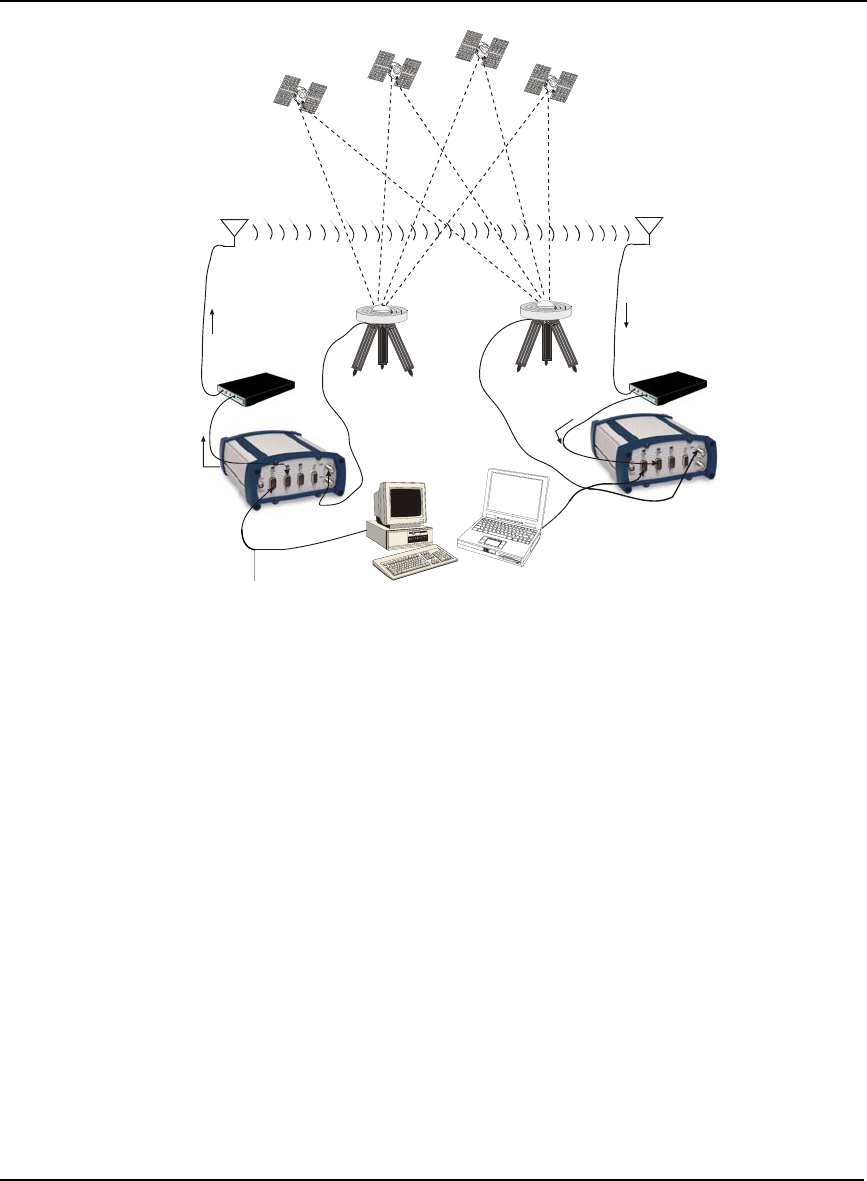
84 OEMV Family Installation and Operation User Manual Rev 5B
Chapter 5 Positioning Modes of Operation
Figure 26: Typical Differential Configuration
Reference Description Reference Description
1 GPS Constellation 7 GPS Receiver
2 Radio Data Link 8 Base Station
3 GPS Antenna with Choke Ring 9 Rover Station
4 Modem
5 Differential Corrections Input
6 Differential Corrections Output
The Rover Station
A rover station is generally any receiver whose position is of unknown accuracy, but has ties to a base
station through an established data link. If the rover station is not receiving differential corrections
from the base station, it is essentially utilizing single-point positioning measurements for its position
solutions, thus is subject to the various GPS system biases. However, when the rover GPS receiver is
receiving a pseudorange correction from the base station, this correction is applied to the local
receiver’s measured pseudorange, effectively cancelling the effects of orbital and atmospheric errors
(assuming baselines < 50 km), as well as eliminating satellite clock error.
The rover station must be tracking the same satellites as the base station in order for the corrections to
take effect. Thus, only common satellite pseudoranges utilize the differential corrections. When the
rover is able to compute its positions based on pseudorange corrections from the base station, its
position accuracies approach that of the base station. Remember, the computed position solutions
from the receiver are always that of its antenna’s phase centre.
1
2
3
4
5
67
89

Positioning Modes of Operation Chapter 5
OEMV Family Installation and Operation User Manual Rev 5B 85
5.4 L-Band Positioning
The transmission of OmniSTAR or CDGPS corrections are from geostationary satellites. The L-Band
frequency of geostationary satellites is sufficiently close to that of GPS that a common, single
antenna, such as the NovAtel GPS-702L, may be used.
Both systems are portable and capable of sub-meter accuracy over their coverage areas. See also
Figure 29, L-Band Concept on Page 89.
The OmniSTAR system is designed for coverage of most of the world’s land areas. A subscription
charge by geographic area is required. The CDGPS system is a free Canada-wide DGPS service that is
accessible coast-to-coast, throughout most of the continental United States, and into the Arctic.
5.4.1 Coverage
The two systems provide different coverage:
• OmniSTAR - Most of the World’s Land Areas
• CDGPS - Canada/America-Wide
OmniSTAR Geographic Areas
In most world areas, a single satellite is used by OmniSTAR to provide coverage over an entire
continent - or at least very large geographic areas. In North America, a single satellite is used, but it
needs three separate beams to cover the continent. The three beams are arranged to cover the East,
Central, and Western portions of North America. The same data is broadcast over all three beams, but
the user system must select the proper beam frequency. The beams have overlaps of several hundred
miles, so the point where the frequency must be changed is not critical.
The North American OmniSTAR Network currently consists of ten permanent base stations in the
Continental U.S., plus one in Mexico. These eleven stations track all GPS satellites above 5 degrees
elevation and compute corrections every 600 milliseconds. The corrections are sent to the OmniSTAR
Network Control Center (NCC) in Houston via wire networks. At the NCC these messages are
checked, compressed, and formed into packets for transmission up to the OmniSTAR satellite
transponder. This occurs every few seconds. A packet contains the latest corrections from each of the
North American base stations.
All of the eastern Canadian Provinces, the Caribbean Islands, Central America (south of Mexico), and
South America is covered by a single satellite (AM-Sat). A single subscription is available for all the
areas covered by this satellite.
OmniSTAR currently has several high-powered satellites in use around the world. They provide
coverage for most of the world's land areas. Subscriptions are sold by geographic area. Any Regional
OmniSTAR service center can sell and activate subscriptions for any area. They may be arranged prior
to travelling to a new area, or after arrival. Contact OmniSTAR at www.omnistar.com for details.
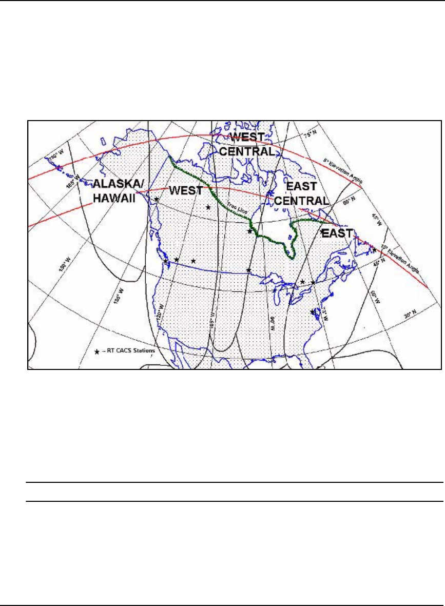
86 OEMV Family Installation and Operation User Manual Rev 5B
Chapter 5 Positioning Modes of Operation
Canada/America-Wide CDGPS
In order to enable CDGPS positioning, you must set the L-Band frequency for the geographically
appropriate CDGPS signal using the ASSIGNLBAND command. See also Section 5.4.3, L-Band
Commands and Logs starting on Page 90 for information on this command.
The CDGPS signal is broadcast on 4 different spot beams on the MSAT-1 satellite. Depending on your
geographic location, there is a different frequency for the CDGPS signal as shown in Figure 27 on
Page 86.
Figure 27: CDGPS Frequency Beams
The following are the spot beam names and their frequencies (in KHz or Hz):
East 1547646 or 1547646000
East-Central 1557897 or 1557897000
West-Central 1557571 or 1557571000
West 1547547 or 1547547000
The CDGPS service does not include the MSAT Alaska/Hawaii beam shown in Figure 27.
The data signal is structured to perform well in difficult, or foliated conditions, so the service is
available more consistently than other services and has a high degree of service reliability.
CDGPS features wide area technology, possible spatial integrity with all Government of Canada maps
and surveys 1 2, 24-hour/7 days-a-week built-in network redundancies and an openly published
broadcast protocol.
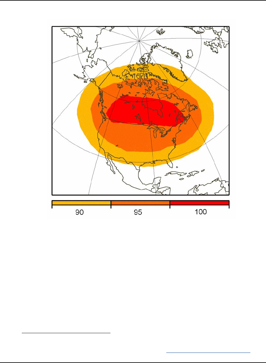
Positioning Modes of Operation Chapter 5
OEMV Family Installation and Operation User Manual Rev 5B 87
Figure 28 on Page 87 is a conservative map of the coverage areas that CDGPS guarantee. The
coverage may be better in your area.
Figure 28: CDGPS Percentage (%) Coverage Map
In Figure 28, 100% coverage means that a correction is received for every visible satellite (at or above
10 degrees). 90% coverage means that a correction is received for 90% of visible satellites. For
example, if a user views 10 satellites but has 90% coverage then there are no corrections available for
one of the satellites. In that case, our firmware shows that a correction is missing for that PRN and
excludes it from the position calculation.
1. If the coordinates are output using the CSRS datum, refer to the DATUM command.
2. The Geological Survey of Canada website is at http://gsc.nrcan.gc.ca/index_e.php.

88 OEMV Family Installation and Operation User Manual Rev 5B
Chapter 5 Positioning Modes of Operation
5.4.2 L-Band Service Levels
Two levels of service are available:
Standard - Sub-meter accuracy from OmniSTAR VBS (subscription required)
and CDGPS
Extra Performance - Decimeter accuracy from OmniSTAR XP (subscription required)
High Performance - Sub-decimeter accuracy from OmniSTAR HP (subscription required)
Standard Service
The OmniSTAR VBS service uses multiple GPS base stations in a solution and reduces errors due to
the GPS signals travelling through the atmosphere. It uses a wide area DGPS solution (WADGPS) and
data from a relatively small number of base stations to provide consistent accuracy over large areas. A
unique method of solving for atmospheric delays and weighting of distant base stations achieves sub-
meter capability over the entire coverage area - regardless of your location relative to any base station.
CDGPS is able to simultaneously track two satellites, and incorporate the corrections into the
position. The output is SBAS-like (see WAAS32-WAAS45 in the OEMV Firmware Reference
Manual), and can incorporate these corrections to generate differential-quality position solutions.
CDGPS allows anyone within the area of coverage to take advantage of its benefits.
CDGPS\OmniSTAR VBS services are available on OEMV-1, OEMV-1G and OEMV-3-based products.
NovAtel’s DL-V3 and ProPak-V3 provide GNSS positions with L-Band corrections in one unit, using
a common antenna. This means that, with CDGPS or a subscription to the OmniSTAR VBS service,
the DL-V3 or ProPak-V3 are high quality receivers with sub-meter positioning capabilities. To obtain
OmniSTAR VBS corrections, your receiver must have a VBS subscription from OmniSTAR.
The position from the OEMV receiver is used as the L-Band system’s first approximation.
After the L-Band processor has taken care of the atmospheric corrections, it then uses its location
versus the base station locations, in an inverse distance-weighted least-squares solution. L-Band
technology generates corrections optimized for the location. It is this technique that enables the L-
Band receiver to operate independently and consistently over the entire coverage area without regard
to where it is in relation to the base stations.
High Performance Service
The OEMV-3, DL-V3 or ProPak-V3 with the software model for OmniSTAR High Performance (HP)
service gives you more accuracy than with the OmniSTAR VBS or CDGPS services. OmniSTAR HP
computes corrections in dual-frequency RTK float mode (within about 10 cm accuracy). The XP
service is similar to HP but less accurate (15 cm) and more accurate than VBS (1 m). HP uses
reference stations while XP uses clock model data from Nasa’s Jet Propulsion Laboratory (JPL). To
obtain HP or XP corrections, your receiver must have an HP or XP subscription from OmniSTAR.
1. For optimal performance, allow the OmniSTAR HP or XP solution to converge prior to
starting any dynamic operation.
2. OmniSTAR XP is now available over a wider coverage area than previously.
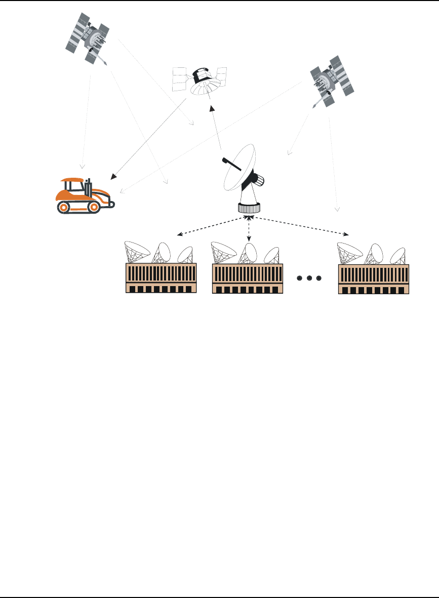
Positioning Modes of Operation Chapter 5
OEMV Family Installation and Operation User Manual Rev 5B 89
Figure 29: L-Band Concept
Reference Description
1 GPS satellites
2 Multiple L-Band ground stations
3 Send GPS corrections to 4
4 Network Control Center where data corrections are checked and
repackaged for uplink to 6
5 DGPS uplink
6 L-Band geostationary satellite
7 L-Band DGPS signal
8 Correction data are received and applied real-time
1
6
7
5
22 2
3
33
8
1
4

90 OEMV Family Installation and Operation User Manual Rev 5B
Chapter 5 Positioning Modes of Operation
5.4.3 L-Band Commands and Logs
The ASSIGNLBAND command allows you to set OmniSTAR or CDGPS base station
communication parameters. It should include a relevant frequency and data rate, for example:
assignlband omnistar 1536782 1200
or,
assignlband cdgps 1547547 4800
The PSRDIFFSOURCE command lets you identify from which source to accept RTCA1, RTCM1,
CDGPS or OmniSTAR VBS differential corrections. For example, in the PSRDIFFSOURCE
command, OMNISTAR enables OmniSTAR VBS and disables other DGPS types. AUTO means the
first received RTCM or RTCA message has preference over an OmniSTAR VBS or CDGPS message.
The RTKSOURCE command lets you identify from which source to accept RTK (RTCM, RTCMV3,
RTCA, CMR, CMRPLUS and OmniSTAR HP) differential corrections. For example, in the
RTKSOURCE command, OMNISTAR enables OmniSTAR HP or XP, if allowed, and disables other
RTK types. AUTO means the NovAtel RTK filter is enabled and the first received RTCM, RTCA or
CMR message is selected and the OmniSTAR HP or XP message, if allowed, is enabled. The position
with the best standard deviation is used in the BESTPOS log.
The HPSEED command allows you to specify the initial position for OmniSTAR HP.
The HPSTATICINIT command allows you to speed up the convergence time of the HP or XP process
when you are not moving.
The PSRDIFFSOURCE and RTKSOURCE commands are useful when the receiver is receiving
corrections from multiple sources.
Several L-Band specific logs also exist and are prefixed by the letters RAWLBAND, LBAND or
OMNI. CDGPS corrections are output similarly to SBAS corrections. There are four SBAS fast
corrections logs (WAAS32-WAAS35) and one slow corrections log (WAAS45) for CDGPS. The
CDGPS PRN is 209.
1. In addition to a NovAtel receiver with L-Band capability, a subscription to the
OmniSTAR, or use of the free CDGPS, service is required. Contact NovAtel for details,
see Customer Service on Page 18.
2. All PSRDIFFSOURCE entries fall back to SBAS (even NONE) for backwards
compatibility.
Refer to the OEMV Firmware Reference Manual for more details on individual L-Band commands
and logs.

Positioning Modes of Operation Chapter 5
OEMV Family Installation and Operation User Manual Rev 5B 91
5.5 Carrier-Phase Differential
Carrier-phase algorithms monitor the actual carrier wave itself. These algorithms are the ones used in
real-time kinematic (RTK) positioning solutions - differential systems in which the rover station,
possibly in motion, requires base-station observation data in real-time. Compared to pseudorange
algorithms, much more accurate position solutions can be achieved: carrier-based algorithms can
achieve accuracies of 1-2 cm (RMS).
Kinematic GPS using carrier-phase observations is usually applied to areas where the relation
between physical elements and data collected in a moving vehicle is desired. For example, carrier-
phase kinematic GPS missions have been performed in aircraft to provide coordinates for aerial
photography, and in road vehicles to tag and have coordinates for highway features. This method can
achieve similar accuracy to that of static carrier-phase, if the ambiguities can be fixed. However,
satellite tracking is much more difficult, and loss of lock makes reliable ambiguity solutions difficult
to maintain.
A carrier-phase measurement is also referred to as an accumulated doppler range (ADR). At the L1
frequency, the wavelength is 19 cm; at L2, it is 24 cm. The instantaneous distance between a GPS
satellite and a receiver can be thought of in terms of a number of wavelengths through which the
signal has propagated. In general, this number has a fractional component and an integer component
(such as 124 567 967.330 cycles), and can be viewed as a pseudorange measurement (in cycles) with
an initially unknown constant integer offset. Tracking loops can compute the fractional component
and the change in the integer component with relative ease; however, the determination of the initial
integer portion is less straight-forward and, in fact, is termed the ambiguity.
In contrast to pseudorange algorithms where only corrections are broadcast by the base station,
carrier-phase algorithms typically “double difference” the actual observations of the base and rover
station receivers. Double-differenced observations are those formed by subtracting measurements
between identical satellite pairs on two receivers:
ADRdouble difference = (ADRrx A,sat i - ADRrx A,sat j) - (ADRrx B,sat i - ADRrx B,sat j)
An ambiguity value is estimated for each double-difference observation. One satellite is common to
every satellite pair; it is called the reference satellite, and it is generally the one with the highest
elevation. In this way, if there are n satellites in view by both receivers, then there are n-1 satellite
pairs. The difference between receivers A and B removes the correlated noise effects, and the
difference between the different satellites removes each receiver’s clock bias from the solution.
In the RTK system, a floating ambiguity solution is continuously generated from a Kalman filter.
When possible, fixed-integer ambiguity solutions are also computed because they are more accurate,
and produce more robust standard-deviation estimates. Each possible discrete ambiguity value for an
observation defines one lane. That is, each lane corresponds to a possible pseudorange value. There
are a large number of possible lane combinations, and a receiver has to analyze each one in order to
select the correct one. L2 measurements provide additional information making results faster and
more reliable. In summary, NovAtel’s RTK system permits L1/L2 receivers to choose integer lanes
while forcing L1-only receivers to rely exclusively on the floating ambiguity solution.
Once the ambiguities are known, it is possible to solve for the vector from the base station to the rover
station. This baseline vector, when added to the position of the base station, yields the position of the
rover station.

92 OEMV Family Installation and Operation User Manual Rev 5B
Chapter 5 Positioning Modes of Operation
5.5.1 Real-Time Kinematic (RTK)
RT-2 (OEMV-2 and OEMV-3 with AdVance RTK) and RT-20 (OEMV-1 and OEMV-1G) are real-time
kinematic software products developed by NovAtel. They can only be used in conjunction with
NovAtel GPS receivers. A quick comparison of RT-2 and RT-20 is shown in Table 17 below.
Table 17: Comparison of RT-2 and RT-20
NovAtel’s RTK software algorithms utilize both carrier and code phase measurements; thus, the
solutions are robust, reliable, accurate and rapid. While both RT-20 and RT-2 operate along similar
principles, RT-2 achieves its extra accuracy and precision due to its being able to utilize dual-
frequency measurements. Dual-frequency GPS receivers have two main advantages over their single-
frequency counterparts when running RTK software:
1. resolution of cycle ambiguity is possible due to the additional information
2. longer baselines are possible due to the removal of ionospheric errors
Depending on the transmitting/receiving receivers and the message content, various levels of accuracy
can be obtained. Please refer to the particular accuracy as shown in the following table:
Table 18: Summary of RTK Messages and Expected Accuracy
The RTK system in the receiver provides two kinds of position solutions. The Matched RTK position
is computed with buffered observations, so there is no error due to the extrapolation of base station
measurements. This provides the highest accuracy solution possible at the expense of some latency
RT-2 RT-20
GPS Frequencies Utilized L1 and L2 L1
Nominal Accuracy 1 cm (RMS) 20 cm (RMS)
Lane Searching L1/L2 None
Message Formats Transmitting
(Base) Receiving
(Rover) Accuracy
Expected
L1 and L2 RTK:
RTCAOBS with RTCAREF
RTCM Types 18 and 19 with
Types 3 and 22
RTCM Types 20 and 21 with
Types 3 and 22
CMROBS with CMRREF
L1/L2 RT-2 1 cm +1 ppm
RMS (RT-2)
RT-20 20 cm RMS
(RT-20)
L1 only RT-2 or RT-20 20 cm RMS
(RT-20)
L1 RTK:
RTCM Type 59 with Type 3
L1/ L2 or L1 only RT-2 or RT-20 20 cm RMS
(RT-20)
L1 Pseudorange Corrections:
RTCM Type 1
RTCA Type 1
L1/L2 or L1 only Any differential
enabled OEMV 0.45 m RMS
(DGPS)

Positioning Modes of Operation Chapter 5
OEMV Family Installation and Operation User Manual Rev 5B 93
which is affected primarily by the speed of the differential data link. The MATCHEDPOS log contains
the matched RTK solution and can be generated for each processed set of base station observations.
The RTKDATA log provides additional information about the matched RTK solution and shows a
verification flag in the "rtk info" field. It is recommended that you check this verification flag,
especially in severe environments.
The Low-Latency RTK position and velocity are computed from the latest local observations and
extrapolated base station observations. This supplies a valid RTK position with the lowest latency
possible at the expense of some accuracy. The degradation in accuracy is reflected in the standard
deviation and is summarized in Section 5.3.2, Position Solutions starting on Page 82. The amount of
time that the base station observations are extrapolated is provided in the "differential lag" field of the
position log. The Low-Latency RTK system extrapolates for 60 seconds. The RTKPOS log contains
the Low-Latency RTK position when valid and an "invalid" status when a low-latency RTK solution
could not be computed. The BESTPOS log contains the low-latency RTK position when it is valid,
and superior to the pseudorange-based position. Otherwise, it contains the pseudorange-based
position. Similarly, RTKVEL and BESTVEL contains the low-latency RTK velocity.
RT-20 solutions always use floating L1 ambiguities. When valid L2 measurements are available, RT-2
solutions have other solution types that depend on convergence time, baseline length, number of
satellites, satellite geometry and the level of ionospheric activity detected.
RT-2 Performance
RT-2 software, in both static and kinematic modes, provides accuracies of 1 cm +1 ppm RMS for
baselines from 0 to 40 km. A plot of convergence versus baseline length is shown in Figure 30 on
Page 94 for typical multipath, ionospheric, tropospheric, and ephemeris errors, where typical is
described as follows:
• A typical multipath environment would provide no carrier-phase double-difference
multipath errors greater than 2 cm or pseudorange double-difference multipath
errors greater than 2 m on satellites at 11° elevation or greater. For environments
where there is greater multipath, please consult NovAtel Customer Service.
• Typical unmodeled ionospheric, tropospheric and ephemeris errors must be within
2σ of their average values, at a given elevation angle and baseline length. It is
assumed that the tropospheric correction is computed with standard atmospheric
parameters. All performance specifications are based on a PDOP < 2 and
continuous tracking of at least 5 satellites (6 preferred) at elevations of at least 11.5°
on both L1 and L2.
Refer to the GPGST usage box, like this one, in the OEMV Firmware Reference
Manual for a definition of RMS and other statistics.
RTKPOS or BESTPOS logs contain some error due to predictions from base station observations. The
expected error of a RTKPOS or BESTPOS log will be that of the corresponding MATCHEDPOS log
plus the appropriate error from Table 19.
There are no data delays for a matched log and therefore no need to add an additional error factor.
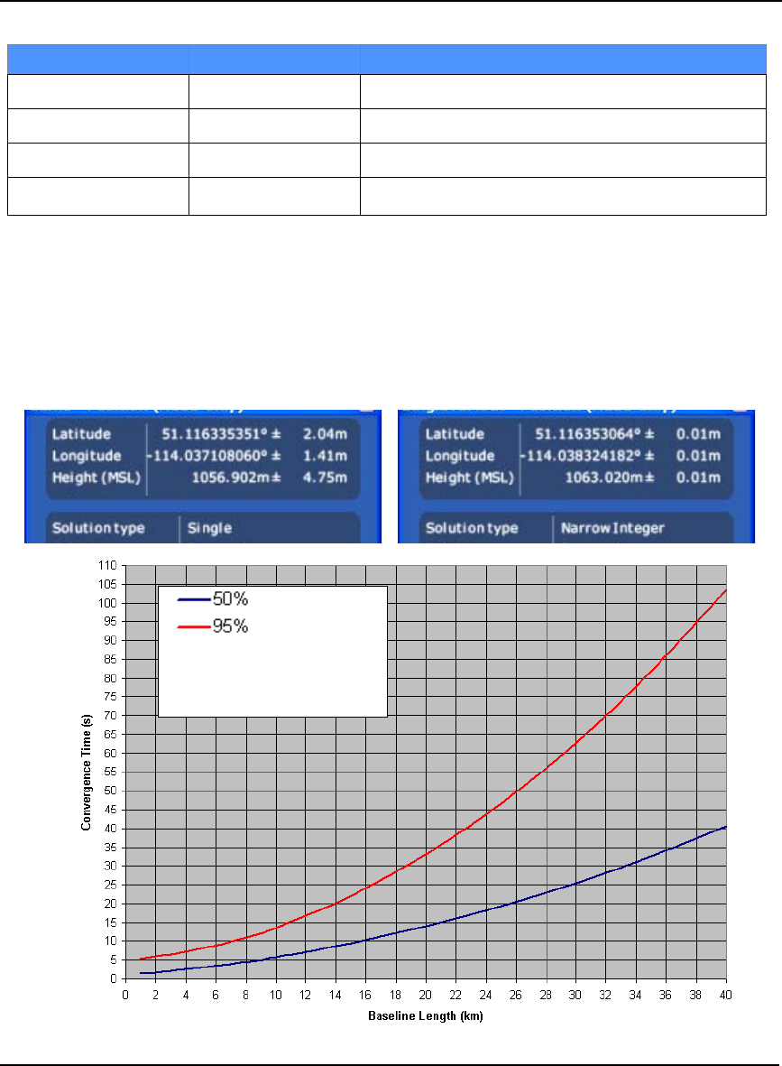
94 OEMV Family Installation and Operation User Manual Rev 5B
Chapter 5 Positioning Modes of Operation
Table 19: RT-2 Degradation With Respect To Data Delay
The RT-2 solution can show two pronounced steps in accuracy convergence; these correspond to the
single-point solution switching to the floating ambiguity solution which in turn switches to the narrow
lane solution. If you were monitoring this using NovAtel’s CDU program, the convergence might
look something like this:
Figure 30: AdVance RTK - Time to Integer Narrowlane vs. Baseline Length
Data Delay (s) Distance (km) Accuracy (RMS)
0 - 2 1+1 cm/s
2 - 7 1+2 cm/s
7 - 30 1+5 cm/s
>60 1single point or pseudorange differential positioning 2
1Mode = Static or Kinematic
2After 60 seconds reverts to pseudorange positioning (single point or differential depending on
messages previously received from the base station).
Time after 5 satellites are
tracking with good parity
conditionsand open sky

Positioning Modes of Operation Chapter 5
OEMV Family Installation and Operation User Manual Rev 5B 95
RT-20 Performance
As shown in Table 20, RT-20 Performance below, Figure 31 on Page 96 and Figure 32 on Page 96
the RT-20 system provides nominal 20 cm accuracy (RMS) after 15 minutes of continuous lock in
static mode. After an additional period of continuous tracking (from 10 to 20 minutes), the system
typically reaches steady state. The time to steady state is about 3 times longer in kinematic mode.
RT-20 double-difference accuracies are based on PDOP < 2 and continuous tracking of at least 5
satellites (6 preferred) at elevations of at least 11.5°.
All accuracy values refer to horizontal RMS error, and are based on low-latency positions. The level
of position accuracy at any time will be reflected in the standard deviations output with the position.
Table 20: RT-20 Performance
Tracking
Time (s) Mode 1Data Delay
(s) Distance
(km) Accuracy (RMS)
1 - 180 Static 0 1 45 to 25 cm
180 - 3000 Static 0 1 25 to 5 cm
> 3000 Static 0 1 5 cm or less 2
1 - 600 Kinematic 0 1 45 to 25 cm
600 - 3000 Kinematic 0 1 25 to 5 cm
> 3000 Kinematic 0 1 5 cm or less 2
Either 0 - 2 1+1 cm/s
Either 2 - 7 1+2 cm/s
Either 7 - 30 1+5 cm/s
Either > 30 1pseudorange or single point 3
Either 00 - 10 +0.5 cm/km
Either 010 - 20 +0.75 cm/km
Either 020 - 50 +1.0 cm/km
1 Mode = Static or Kinematic (during initial ambiguity resolution)
2 The accuracy specifications refer to the BESTPOSA/B logs which include about 3 cm
extrapolation error. MATCHEDPOSA/B logs are more accurate but have increased
latency associated with them.
3 After 60 seconds reverts to pseudorange positioning (single point or differential
depending on messages previously received from the base station).
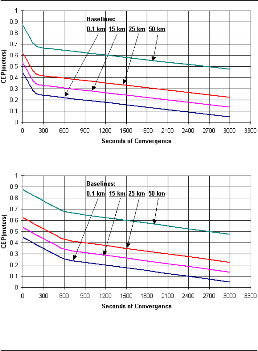
96 OEMV Family Installation and Operation User Manual Rev 5B
Chapter 5 Positioning Modes of Operation
Figure 31: Typical RT-20 Convergence - Static Mode
Figure 32: Typical RT-20 Convergence - Kinematic Mode

Positioning Modes of Operation Chapter 5
OEMV Family Installation and Operation User Manual Rev 5B 97
Performance Considerations
When referring to the “performance” of RTK software, two factors are introduced:
1. Baseline length: the position estimate becomes less precise as the baseline length increases.
Note that the baseline length is the distance between the phase centres of the two antennas.
Identifying the exact position of your antenna’s phase centre is essential; this information is
typically supplied by the antenna’s manufacturer or vendor.
The RTK software automatically makes the transition between short and longer baselines,
but the best results are obtained for baselines less than 10 km. The following are factors
which are related to baseline length:
• ephemeris errors - these produce typical position errors of 0.75 cm per 10 km of
baseline length.
• ionospheric effects - the dominant error for single-frequency GPS receivers on
baselines exceeding 20 km. Differential ionospheric effects reach their peak at
around 2 pm local time, being at a minimum during hours of darkness.
• tropospheric effects - these produce typical position errors of approximately 1 cm
per 20 km of baseline length. This error increases if there is a significant height
difference between the base and rover stations, as well as if there are significantly
different weather conditions between the two sites.
A related issue is that of multipath interference, the dominant error on short differential base-
lines. Generally, multipath can be reduced by choosing the antenna’s location with care, and
by the use of the GPS-702 antenna (no need for a choke ring) or a L1/L2 antenna and a choke
ring antenna ground plane, refer to the Multipath section of the GPS+ Reference Manual.
2. Convergence time: the position estimate becomes more accurate and more precise with time.
However, convergence time is dependent upon baseline length: while good results are
available after a minute or so for short baselines, the time required increases with baseline
length. Convergence time is also affected by the number of satellites which can be used in the
solution (the more satellites, the faster the convergence) and by the errors listed in Baseline
Length above.
Performance Degradation
The performance will degrade if satellites are lost at the rover or if breaks occur in the differential
correction transmission link. The degradations related to these situations are described in the
following paragraphs.
Provided lock is maintained on at least 4 SVs and steady state has been achieved, the only degradation
will be the result of a decrease in the geometrical strength of the observed satellite constellation. If
steady state has not been achieved, then the length of time to ambiguity resolution under only
4-satellite coverage will be increased significantly.

98 OEMV Family Installation and Operation User Manual Rev 5B
Chapter 5 Positioning Modes of Operation
ROVER TRACKING LOSS
If less than 4 satellites are maintained, then the RTK filter can not produce a position. When this
occurs, the BESTPOS and PSRPOS logs will be generated with differential (if pseudorange
differential messages are transmitted with RTK messages) or single point pseudorange solutions if
possible.
DIFFERENTIAL LINK BREAKDOWN
1. Provided the system is in steady state, and the loss of observation data is for less than 60
seconds, the Low-Latency RTK positions will degrade according to the divergence of the
base observation extrapolation filters. This causes a decrease in accuracy of about an order of
magnitude per 10 seconds without a base station observation, and this degradation is
reflected in the standard deviations of the low latency logs. Once the data link has been re-
established, the accuracy will return to normal after several samples have been received.
2. If the loss of differential corrections lasts longer than 60 seconds, the RTK filter is reset and
all ambiguity and base model information is lost. The timeout threshold for RTK differential
corrections is 60 seconds, but for Type 1 pseudorange corrections, the default timeout is 300
seconds. Therefore, when the RTK can no longer function because of this timeout, the
pseudorange filter can produce differential positions for an additional 240 seconds by default
(provided pseudorange differential messages were transmitted along with the RTK
messages) before the system reverts to single point positioning. Furthermore, once the link is
re-established, the pseudorange filter produces an immediate differential position while the
RTK filter takes several additional seconds to generate its positions. The base model must be
healthy before solutions are logged to the low latency logs, so there is a delay in the use of
real time carrier positioning to the user once the link has been re-established. The RTK logs,
such as MATCHEDPOSA/B, use matched observations only (no extrapolated observations).
These matched observations will be available after three base observations are received, but
will typically have about 1.5 seconds latency associated with them, although longer latencies
may occur with some slower data links.
3. The RTK system is based on a time-matched double difference observation filter. This means
that observations at the rover site have to be buffered while the base station observation is
encoded, transmitted, and decoded. Only 8 seconds of rover observations are saved, so the
base station observation transmission process has to take less than 8 seconds if any time
matches are to be made. In addition, only rover observations on even second boundaries are
retained, so base station observations must also be sent on even seconds if time matches are
to be made.

OEMV Family Installation and Operation User Manual Rev 5B 99
Chapter 6 PC Software and Firmware
Visit the Firmware and Software Updates section of the NovAtel website, www.novatel.com, for the
most recent versions of the PC software and receiver firmware.
6.1 CDU/Convert/DLVTool Installation
The CD accompanying this manual contains the Windows applications CDU (Control and Display
Unit), Convert and DLVTool. They are installed via a standard Install Shield set-up application. Also
included on the CD is sample source code, to aid development of software for interfacing with the
receiver, and product documentation.
These applications utilize a database in their operations so the necessary components of the Borland
Database Engine (BDE) are installed as well as the necessary database tables and an alias for the
database. The install set-up application does all this automatically so you have only to select where
you would like the applications installed on your PC. It is strongly recommended that you close all
applications before installing CDU, Convert and DLVTool. You must close any applications that may
be using the BDE before installing. The install set-up modifies the BDE configuration so that it can
recognize the new CDU, Convert and DL4Tool database.
The software operates from your PC’s hard drive. You will need to install the software from the CD
supplied by NovAtel or from our website:
1. Start Microsoft Windows.
2. Place the NovAtel CD in your CD-ROM drive. If the setup utility is not automatically accessible,
follow these steps:
a. Select Run from the Start menu.
b. Select the Browse button.
c. Locate Setup.exe on the CD drive and select Open.
d. Select OK to run the setup utility.
3. Advance through the steps provided by the setup utility.
When the installation is complete, click on a program icon to launch the application.
DLVTool (for the DL-V3) and DL4Tool (for the DL-4plus) is available to download from our
website at http://www.novatel.com/support/fwswupdates.htm. Log groups are sets of logs
used by the DL-V3. A log group can be created in DLVTool and then downloaded to the DL-
V3. Refer to the DL-V3 Firmware Reference Manual, on our website at http://
www.novatel.com/support/docupdates.htm, for more details on DLVTool and its use. If
applicable, refer also to your DL-V3 Quick Start Guide.
6.2 CDU
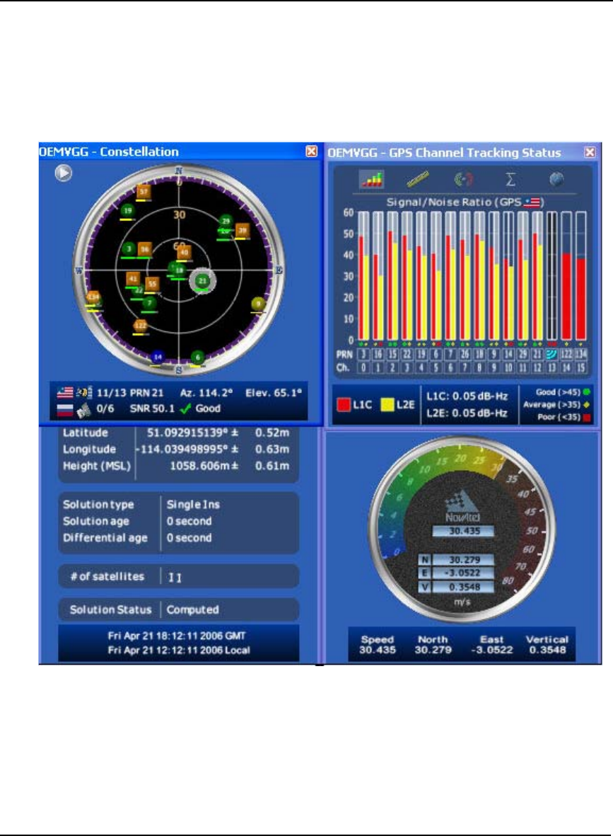
100 OEMV Family Installation and Operation User Manual Rev 5B
Chapter 6 PC Software and Firmware
CDU is a 32-bit Windows application. The application provides a graphical user interface (GUI) to
allow you to set-up and monitor the operation of the NovAtel receiver by providing a series of
windows whose functionality is explained in this section. A help file is included with CDU. To access
the file, select Contents from the Help menu.
See also Section 4.2.2, Communicating with the Receiver Using CDU starting on Page 58.
The rest of this section shows the CDU windows from the View menu and their descriptions.
Most windows have a popup menu accessible by right clicking on the window with the mouse. They
provide a way to customize the window by changing the font or to print the window contents. Some of
the windows have access to the Options dialog which contains further settings for certain windows.
•Constellation Window: The Constellation window displays each satellite being tracked by the
receiver. When you select a satellite, the window shows details of its PRN, Signal to Noise Ratio
(SNR), azimuth and elevation. Concentric circles from 0° to 90° represent elevations from the
horizon to directly overhead, respectively. The azimuth is mapped on a compass relative to true

PC Software and Firmware Chapter 6
OEMV Family Installation and Operation User Manual Rev 5B 101
North. The colored rings indicate the lowest elevation cut-off angles at which satellites are
tracked and can be changed or viewed via the button.
Each of the satellites being tracked are represented with icons according to their satellite system
as follows:
• Circular for GPS
• Square for GLONASS
• Hexagon for SBAS
There are also information icons and values at the bottom of the window:
• The number of GPS/GLONASS satellites used in the solution verses the number
being tracked. For example, 0/5 next to the Russian flag means that while the
receiver is tracking 5 GLONASS satellites, none are currently used in the position
solution.
• Satellite PRN number Azimuth and elevation angle values
• Signal to Noise Ratio (SNR) value and indicator
The PRN of the satellite is displayed on the icon and color-coding is used to indicate the status of
the satellite or the tracking channel. Click on a satellite to display information on that satellite.
When a valid position has been achieved, dilution of precision (DOP) values can be viewed in the
DOP window.
Open this window by selecting Constellation Window from the View menu or by clicking
its button in the Window Toolbar.
•Channel Tracking Status Window: The Channel Tracking Status window displays key
information for each of the receiver's processing channels, including the PRN of the satellite
being tracked by that channel, the Signal to Noise Ratio, Pseudorange measurements, Doppler
values, Residuals measurements and Lock Time from the satellite.
The TRACKSTAT log provides the data for many of the fields listed in this window. The number
of channels displayed depends on the model of your receiver and the bars are color-keyed to indi-
cate the frequency type on the channel.
Open these windows by selecting Tracking Status Window GPS/GLONASS
from the View menu or by selecting the American and Russian flag buttons in the Window Tool-
bar.
•Position Window: The Position window displays:
• The receiver's latitude, longitude and height
• The Solution Type, also known as Position Type
• The solution or differential age (number of seconds the current solution has been
valid). Normally this represents the latency in the correction data.
102 OEMV Family Installation and Operation User Manual Rev 5B
Chapter 6 PC Software and Firmware
• The number of satellites used in the solution
• The Solution Status
• The receiver's date and time (GMT and local)
Open this window by selecting Position Window from the View menu or its button in
the Window Toolbar.
Right-click in the Position window to that enables you to set the PC clock to the receiver's time,
change the font used to display the position data or set the units through the Options dialog box.
•Velocity Window: The Velocity window displays vertical and horizontal speed and direction.The
numeric displays within the dial, and the velocity values below the dial, show the vector velocity
as well as the vertical, North, and East velocity components. If necessary, the scale in the dial
increases so that you have room to accelerate.
Open this window by selecting Velocity Window from the View menu or its button in
the Window Toolbar.
• Compass Window: The direction dial is a compass that displays the direction of motion of the
receiver over ground and its elevation (both in degrees). The white arrow indicates the elevation
value on the vertical scale down the centre of the dial. The black arrow on the outer rim of the dial
indicates the Track Over Ground value. Both the track over ground and elevation angles are also
shown at the bottom of the Compass window.
Open this window by selecting Compass Window from the View menu or its button in
the Window Toolbar.
•INS Window: If applicable, please refer to your SPAN User Manual for more on INS.
Information in the INS Position, Velocity, Attitude window is only available if you have an INS-
capable receiver model.
The dial is a graphical display of the Roll, Pitch and Azimuth values indicated by an arrow on
each axis.
Open this window by selecting INS Window from the View menu or its button in the
Window Toolbar.
•Plan Window: The Plan window provides real-time graphic plotting of the current position of
each connected device. The latitude and longitude shown at the bottom of the window indicate
the receiver's reference position, which is used as the center of the grid system. The receiver's
subsequent positions, shown with a yellow + marker, are given relative to this initial starting

PC Software and Firmware Chapter 6
OEMV Family Installation and Operation User Manual Rev 5B 103
point. The current position is shown with a red + marker.
The buttons at the top of the window provide options for controlling the plan display:
• Zoom in or out of the Plan window
• View all configurations or center in on the active configuration
• Select a grid or circular display
• Show/Hide history
• Delete all history (no undo)
To open this window, select Plan Window from the View menu or select its button in the
Window Toolbar.
• Doppler Window: A value representing the uncertainty of the position solution based on
the current satellite geometry. The lower the value, the greater the confidence in the solution.
In the DOP window, DOP is displayed in the following forms:
• GDOP Geometric DOP: Uncertainty of all parameters (latitude,
longitude, height, clock offset)
• PDOP Position DOP: Uncertainty of the three-dimensional
parameters (latitude, longitude, height)
• HDOP Horizontal DOP: Uncertainty of the two-dimensional
parameters (latitude, longitude)
• VDOP Vertical DOP: Uncertainty of the height
• TDOP Time DOP: Uncertainty of the clock offset
•Console Window: This window allows the user to communicate directly to the receiver through
the serial port. It is essentially a terminal emulator with added receiver functionality. Commands
can be issued to the receiver via the command editor (at the bottom of the window) and sent by
pressing the Enter button or simply pressing <Enter> on the keyboard. The command editor has
recall functionality similar to DosKey whereby pressing the up arrow on the keyboard will move
backward through the previously issued commands and pressing the down arrow will move
forward through the previously issued commands. This allows the user to scroll through
previously issued commands and then press the <Enter> key to issue that command again.
Feedback from the receiver is displayed in the ASCII Messages or Console window depending on
the format of the message (ASCII or Abbreviated ASCII respectively).
WARNING!: Ensure all other windows are closed in CDU when entering the SAVECONFIG
command in the Console window.

104 OEMV Family Installation and Operation User Manual Rev 5B
Chapter 6 PC Software and Firmware
This window automatically opens when CDU is first connected to a receiver. To bring
the window to the front, select Console Window from the View menu or click its button in the
Window Toolbar.
•Logging Control Window: The Logging Control window provides a graphical interface for:
• Initiating data logging to a file
• Initiating logging to the receiver's serial ports
• Specifying a time window for data logging
• Stopping logging
• Editing log settings
To display the Logging Control window, select Logging Control Window from the
Tools menu or select its button in the Window Toolbar.
WARNING!: Ensure the Power Settings on your PC are not set to go into Hibernate or
Standby modes. Data will be lost if one of these modes occurs during a logging
session. Refer to CDU’s online Help for more information.
•ASCII Messages Window: This window displays ASCII formatted NovAtel logs.
To display the ASCII Messages window, select ASCII Messages Window from the View
menu or select its button in the Window Toolbar.
•Wizards: There are two wizards available: RTK and SPAN.
The Real Time Kinematic (RTK) wizard takes you through the steps needed to set up your RTK
system. You must have an RTK-capable receiver model or the wizard does not continue past its
opening page.
The SPAN wizard takes you through the steps needed to set up your Synchronized Position
Attitude Navigation (SPAN) system. You must have a SPAN-capable receiver model, or the
wizard does not continue past its opening page. The SPAN wizard can help with the alignment or
calibration of a SPAN system.
To display a wizard window, if you have the necessary receiver model, select
SPAN Wizard or RTK Wizard from the Tools menu or select one of their buttons in the Window
Toolbar.
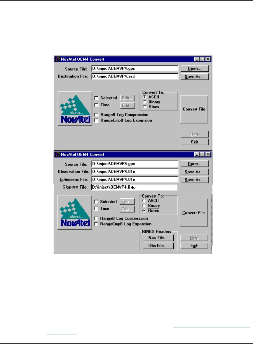
PC Software and Firmware Chapter 6
OEMV Family Installation and Operation User Manual Rev 5B 105
6.3 Convert
Convert is a 32-bit Windows application and is shown in Figure 33. Convert will accept GPS file
formats and convert them to ASCII, Binary or Rinex format. The application also allows the user to
screen out particular logs by selecting the desired logs from the list of available logs. This feature is
useful for screening particular logs out of large data files in either ASCII or Binary formats.
Figure 33: Convert Screen Examples
6.3.1 Rinex Format
The Receiver-Independent Exchange (RINEX1) format is a broadly-accepted, receiver-independent
format for storing GPS data. It features a non-proprietary ASCII file format that can be used to
combine or process data generated by receivers made by different manufacturers.
1. For further information on RINEX Version 2.10 file descriptions, you may wish to
consult the U.S. National Geodetic Survey website at http://www.ngs.noaa.gov/CORS/
Rinex2.html.

106 OEMV Family Installation and Operation User Manual Rev 5B
Chapter 6 PC Software and Firmware
The Convert4 utility can be used to produce RINEX files from NovAtel receiver data files.
Although RINEX is intended to be a receiver-independent format, there are many optional
records and fields. Please keep this in mind when combining NovAtel and non-NovAtel
RINEX data.
When converting to RINEX, two files are produced - a RINEX observation file and a RINEX
navigation file. A third GLONASS file is produced if the data contains GLONASS observations. The
default names of these files conform to the RINEX Version 2.10 recommended naming convention of
ssssdddf.yyt, where:
ssss 4 character station name - Convert4 uses the first four characters of the <infile>
parameter as the station ID
ddd day of year
f file sequence number within the day - Convert4 sets this to zero
t file type: o for the observation and n for the navigation file
Selecting the RINEX field, see Figure 33, Convert Screen Examples on Page 105, in the Convert To
section causes the:
1. Destination File: field to be replaced by the Observation File: and Ephemeris File: fields. Note
that Observation File refers to the RINEX OBS file while Ephemeris File refers to the RINEX
NAV file.
2. RINEX Headers buttons to appear allowing you to supply additional information that appears in
the header records of the RINEX output files (for example, Company Name, Marker Name and
Marker Number).
For best results, the NovAtel receiver input data file should contain the logs as in Table 21, NovAtel
Logs for Rinex Conversion on Page 107.
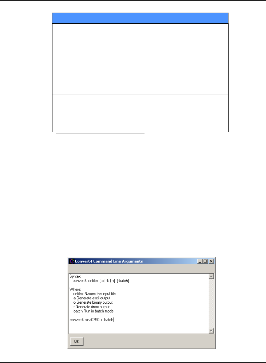
PC Software and Firmware Chapter 6
OEMV Family Installation and Operation User Manual Rev 5B 107
Table 21: NovAtel Logs for Rinex Conversion
6.3.2 Convert Command Line Switches
Convert4 supports several command-line switches to facilitate batch processing. To access its
Command Line Arguments window, open a command prompt window (select Accessories |
Command Prompt from the Start menu). Change directory (cd) to the directory on your hard drive that
Convert4 is stored. Type the following: convert4 -h
The Convert4 Command Line Arguments window appears as shown in Figure 34.
Figure 34: Convert Command Line Arguments
NovAtel OEMV Family Log Recommended Trigger
RANGEA/B, or
RANGECMPA/B ontime 15
BESTPOSA/B, or
PSRPOSA/B, or
RTKPOSA/B, or
MARKPOSA/B
once
IONUTCA/B onchanged
RAWEPHEMA/B onchanged
GLORAWEPHEMA/B onchanged
VERSIONA/B a
a. Information from this log overrides data entered into the Receiver
Number, Type and Version fields using the OBS file button of the
RINEX Headers section, see Figure 33 on Page 105
once
SITEDEFA/B b
b. Available on DL-V3 receivers, refer to the DL-V3 Firmware
User Manual. Information from this log overrides data
entered into the Marker Name, Marker Number, Antenna
Type and Antenna Delta H fields using the OBS file button of
the RINEX Headers section
once

108 OEMV Family Installation and Operation User Manual Rev 5B
Chapter 6 PC Software and Firmware
The name of the output file is the same as the input file when converting to ASCII or binary formats.
The file extension, however, is altered to indicate the format of the data:
*.asc for ASCII
*.bin for binary
When converting to RINEX, the output files are named according to the RINEX Version 2.10 naming
convention, see Section 6.3.1, Rinex Format on Page 105.
The -batch arguments suppress the window display and convert the specified file automatically.
When converting to RINEX in batch mode, the navigation and observation file header
information from the most recent interactive Convert session is used.
6.4 USB Drivers Installation
The NovAtel USB PC Driver Kit contains the following:
ngpsser.sys This driver provides a virtual serial port for each USB port of the receiver.
ngpsusb.sys This driver connects the virtual serial ports to the USB stack.
novatelusb.exe This utility allows you to control which Windows COM ports are assigned
to each USB port of the receiver. This utility can also be used to uninstall
the drivers when newer versions are available. During installation, a short-
cut is added to the Start Menu under Programs/OEMV PC Software/NovA-
tel USB Configuration Utility.
These drivers have not been certified by Microsoft's Windows Hardware Quality Lab
(WHQL). Depending on your computer's Driver Signing Policy, Windows may refuse to
install this driver or may display a warning. See Section 6.4.1, Windows Driver Signing below
for details.
6.4.1 Windows Driver Signing
Depending on how your administrator has configured your computer, Windows 2000 and Windows
XP either ignore device drivers that are not digitally signed, display a warning when they detect
device drivers that are not digitally signed (the default), or prevent you from installing device drivers
without digital signatures.
Since the current version of NovAtel USB drivers are not digitally signed, the computer's policy must
be either Ignore or Warn to enable the drivers to be installed.
To change the Driver Signing Policy on your computer:
1. Double-click on System in the Control Panel.
2. Select the Hardware tab.
3. Click on the Driver Signing button