Novatel 01017829 GPS Receiver with Bluetooth User Manual Technical Writer
Novatel Inc GPS Receiver with Bluetooth Technical Writer
Novatel >
Contents
- 1. User Manual part 1
- 2. User Manual part 2
User Manual part 2
PC Software and Firmware Chapter 6
OEMV Family Installation and Operation User Manual Rev 5B 109
4. Select either Ignore or Warn in the File signature verification box.
5. Click on OK to accept the new policy.
6. Click on OK again to close the System Properties dialog.
7. Unplug the NovAtel receiver USB cable, plug it back in and follow the installation instructions
described in either the Windows XP Installation section starting below or the Windows 2000
Installation section starting on Page 111.
6.4.2 Windows XP Installation
If upgrading drivers, uninstall older versions using the NovAtel USB Configuration tool located in the
Start Menu under Program Files | OEMV PC Software. If you have not installed NovAtel USB drivers
before, the NovAtel USB Configuration tool will not be there until you install them.
After connecting the NovAtel GPS receiver to a USB port on the PC, the Found New Hardware
wizard appears.
1. The screens displayed in this section, from Windows XP, may vary from what you see
and depend on your operating system.
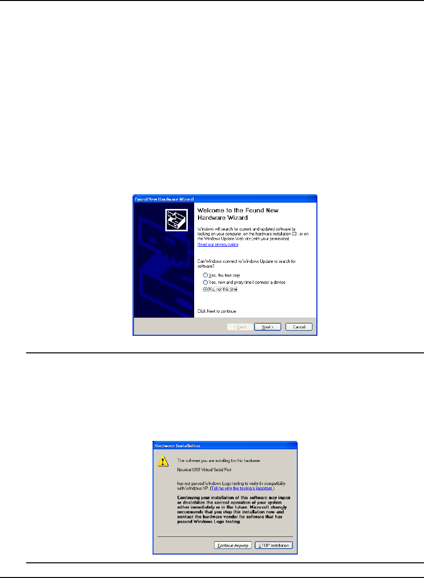
2. During the driver installation you may see a Window Logo testing warning if you
skipped the steps in Section 6.4.1,Windows Driver Signing on Page 108. Our USB
drivers are compatible with Microsoft Windows operating systems. Please click on
Continue Anyway if you see a warning like this:
110 OEMV Family Installation and Operation User Manual Rev 5B
Chapter 6 PC Software and Firmware
1. Click on No, not this time and then click on Next.
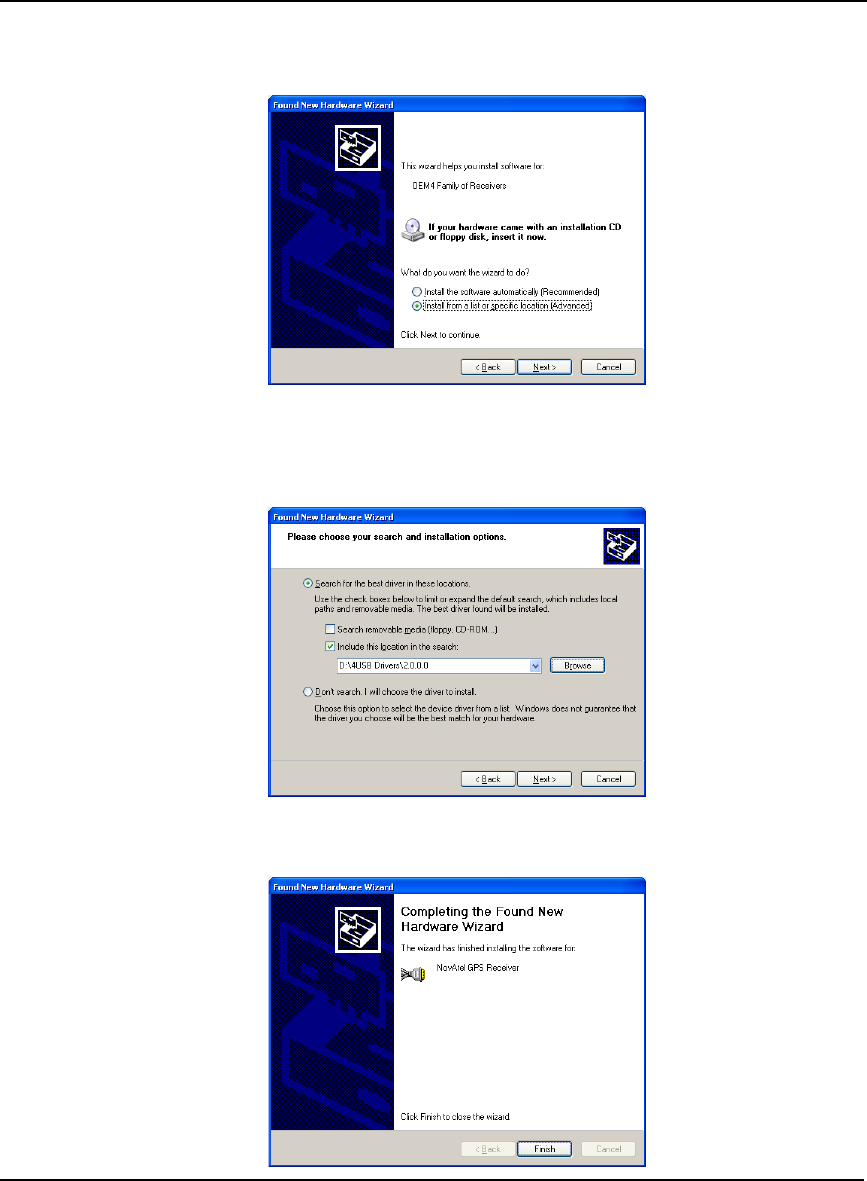
2. Select the Install from a list or specific location (Advanced) field and click on Next.
3. Clear the Search removable media check box, select the Include this location in the search: field
and Browse to the USB driver install directory on the supplied OEMV family CD. Then click on
Next.
4. Click on Finish to complete the driver installation.
PC Software and Firmware Chapter 6
OEMV Family Installation and Operation User Manual Rev 5B 111
After installing the NovAtel USB driver, Windows detects the OEMV-2 or OEMV-3 receiver's new
virtual COM ports and begins to initialize them. As each port is detected, the Found New Hardware
wizard appears.
Complete the following steps for each port:
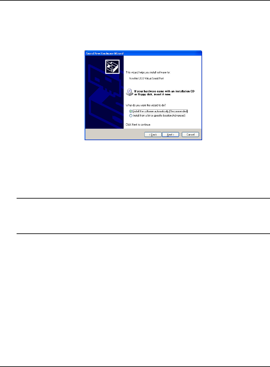
1. Select the Install the software automatically field (recommended) and click on Next.
2. Click on Finish.
Installation is complete when no more dialogs appear. The new COM ports corresponding to the
receiver's USB1, USB2, and USB3 ports are numbered sequentially following the existing ports in the
PC, and are ready to use with any existing application that communicates with the receiver's COM
ports.
The assignment of COM port numbers is tied to the USB port on the PC. This allows you to
switch receivers without Windows assigning new COM ports. However, if you connect the
receiver to a different USB port, Windows detects the receiver's presence on that USB port
and assigns three new COM port numbers.
6.4.3 Windows 2000 Installation
If upgrading drivers, uninstall older version using NovAtel USB Configuration tool located in the
Start Menu under Program Files | OEMV PC Software.
After connecting the NovAtel GPS receiver to a USB port on the PC, the Found New Hardware
wizard appears. Click on Next. (see the example screens and notes in Section 6.4.2, Windows XP
Installation starting on Page 109).
1. Select the Search for a suitable driver for my device field and click on Next.
2. Select the Specify a location field and click on Next.
3. Specify the location using the browse button, for example, on the supplied OEMV family CD:
USB Drivers\Install
4. Click on OK.
5. Confirm that the driver found is, for example: \USB Drivers\Install\ngpsusb.inf

112 OEMV Family Installation and Operation User Manual Rev 5B
Chapter 6 PC Software and Firmware
6. Click on Next.
7. Click on Finish to complete the driver installation.
After installing the drivers, Windows detects the NovAtel receiver's new virtual COM ports and
begins to initialize them. Installation is complete when no more dialogs appear. The new COM ports
corresponding to the receiver's USB1, USB2, and USB3 ports are numbered sequentially following
the existing ports in the PC, and are ready to use with any existing application that communicates with
the receiver's COM ports.
The assignment of COM port numbers is tied to the USB port on the PC. This allows you to
switch receivers without Windows assigning new COM ports. However, if you connect the
receiver to a different USB port, Windows detects the receiver's presence on that USB port
and assign three new COM port numbers.
6.5 Firmware Upgrades
The receiver stores its program firmware in non-volatile memory, which allows you to perform
firmware upgrades without having to return the receiver to the distributor. New firmware can be
transferred to the receiver through COM1, and the unit will immediately be ready for operation at a
higher level of performance.
The first step in upgrading your receiver is to contact your local NovAtel dealer. Your dealer will
assist you in selecting the best upgrade option that suits your specific GPS needs. If your needs are
still unresolved after seeing your dealer then you can contact NovAtel directly through any of the
methods described in the Customer Service section, see Page 18, at the beginning of this manual.
When you call, be sure to have available your receiver model number, serial number, and program
revision level. This information can be found by issuing the LOG VERSION command at the port
prompt.
After establishing which new model/revision level would best suit your needs, and having described
the terms and conditions, you will be issued an authorization code (auth-code). The auth-code is
required to unlock the new features according to your authorized upgrade model type.
To upgrade to a higher performance model at the same firmware revision level (for example,
upgrading from an OEMV-3-L1 to an OEMV-3-RT2 on firmware version 3.000), you can use the
AUTH command with the issued auth-code.
If you are upgrading to a higher firmware revision level (for example, upgrading an OEMV-3-RT2
firmware version 3.000 to OEMV-3-RT2 firmware version 3.100), you will need to transfer new
program firmware to the OEMV family receiver using the WinLoad utility program. As WinLoad and
the upgrade file are generally provided in a compressed file format, you will also be given a
decompression password. WinLoad and the upgrade files can be found on NovAtel's FTP site at http:/
/www.novatel.com, or can be sent to you on disk or by e-mail.
Your local NovAtel dealer will provide you with all the information that you require to upgrade your
receiver.

PC Software and Firmware Chapter 6
OEMV Family Installation and Operation User Manual Rev 5B 113
6.5.1 Upgrading Using the AUTH Command
The AUTH command is a special input command which authorizes the enabling or unlocking of the
various model features. Use this command when upgrading to a higher performance OEMV family
model available within the same revision level as your current model (for example, upgrading from an
OEMV-3-L1 to an OEMV-3-RT2 on firmware version 3.000). This command only functions in
conjunction with a valid auth-code assigned by Customer Service.
The upgrade can be performed directly from CDU's Command Line Screen, or from any other
communications program. The procedure is as follows:
1) Power-up the OEMV family receiver and establish communications over a serial port (see
Chapter 4, Operation on Page 56)
2) Issue the LOG VERSION command to verify the current firmware model number, revision level,
and serial number.
3) Issue the AUTH command, followed by the auth-code and model type. The syntax is as follows:
Syntax:
auth auth-code
where auth is a special command which allows program model upgrades
auth-code is the upgrade authorization code, expressed as hhhh,hhhh,hhhh,hhhh,hhhh,model# where
the h characters are an ASCII hexadecimal code, and the model# would be ASCII text
Example:
auth 17cb,29af,3d74,01ec,fd34,l1l2lrvrt2
Once the AUTH command has been executed, the OEMV family receiver will reboot itself. Issuing
the LOG VERSION command will confirm the new upgrade model type and version number.
If communicating using CDU, the communication path needs to be closed and re-opened using the
Device menu.
6.5.2 Updating Using the WinLoad Utility
WinLoad is required (instead of the AUTH command) when upgrading previously released firmware
with a newer version of program and model firmware (for example, upgrading an OEMV-3-RT2
firmware version 3.000 to OEMV-3-RT2 firmware version 3.100). WinLoad is a Windows utility
program designed to facilitate program and model upgrades. Once WinLoad is installed and running,
it will allow you to select a host PC serial port, bit rate, directory path, and file name of the new
program firmware to be transferred to the OEMV family receiver via its COM1, COM2 or COM3
port. The port chosen must have an RS-232 interface to the PC.
Transferring Firmware Files
To proceed with your program upgrade, you must first acquire the latest firmware revision. You will
need a file with a name such as OEMXXXX.EXE (where XXXX is the firmware revision level). This
file is available from NovAtel's FTP site (http://www.novatel.com), or via e-mail
(support@novatel.ca). If transferring is not possible, the file can be mailed to you on floppy disk. For

114 OEMV Family Installation and Operation User Manual Rev 5B
Chapter 6 PC Software and Firmware
more information on how to contact NovAtel Customer Service please see Page 18 at the beginning
of this manual.
You will need at least 1 MB of available space on your hard drive. For convenience, you may wish to
copy this file to a GPS sub-directory (for example, C:\GPS\LOADER).
The file is available in a compressed format with password protection; Customer Service will provide
you with the required password. After copying the file to your computer, it must be decompressed.
The syntax for decompression is as follows:
Syntax:
[filename] [password]
where filename is the name of the compressed file (but not including the .EXE extension) and
password is the password required to allow decompression
Example:
oem1001 12345678
A windows-based dialog box is provided for password entry.
The self-extracting archive will then generate the following files:
WinLoad.exe WinLoad utility program
HowTo.txt Instructions on how to use the WinLoad utility
WhatsNew.txt Information on the changes made in the firmware since the last revision
XXXX.hex Firmware version upgrade file, where XXXX = program version level (for
example, 1001.hex)
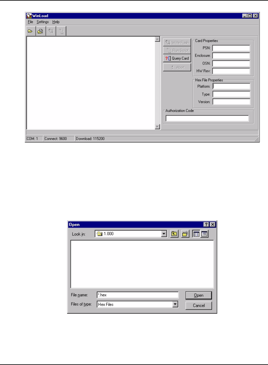
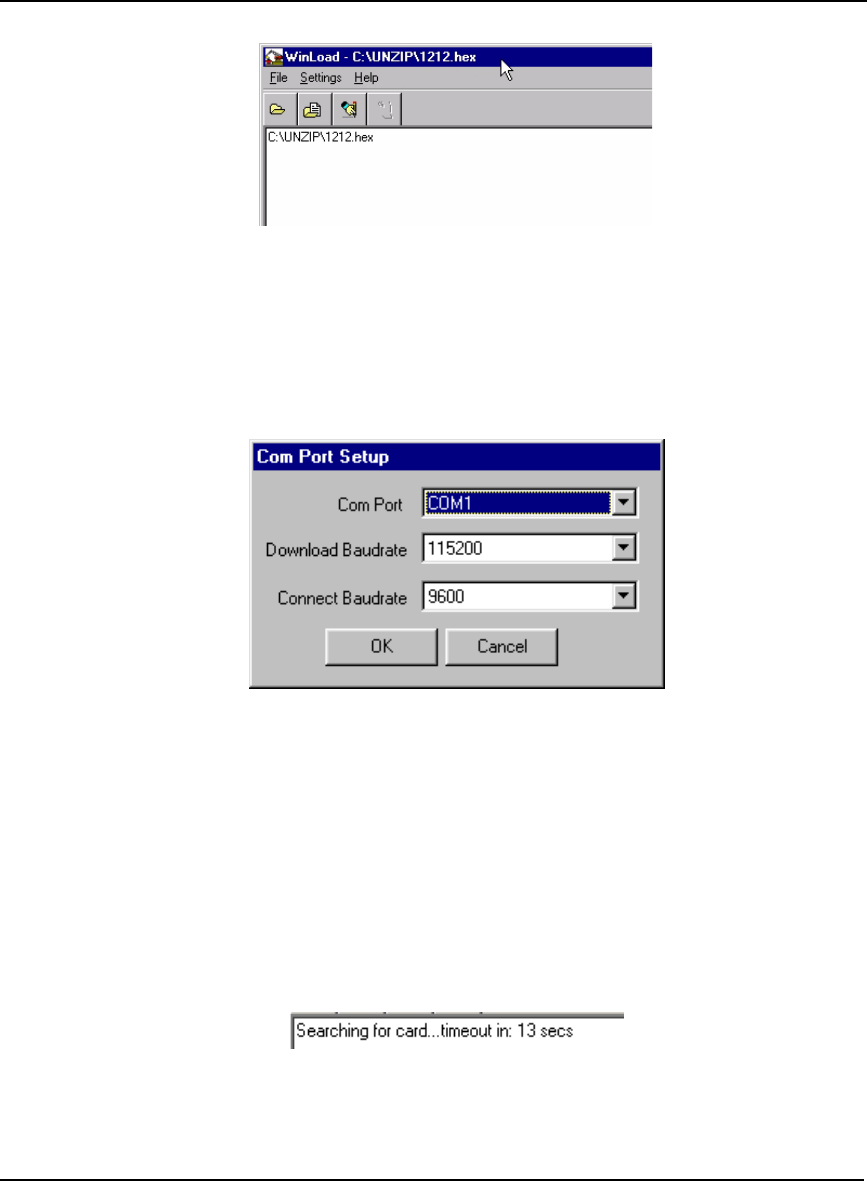
Using the WinLoad Utility
WinLoad is a windows based program used to download firmware to OEMV family cards. The main
screen is shown in Figure 35.
PC Software and Firmware Chapter 6
OEMV Family Installation and Operation User Manual Rev 5B 115
Figure 35: Main Screen of WinLoad
If you are running WinLoad for the first time you will need to make sure the file and communications
settings are correct.
Open a File to Download
From the file menu choose Open. Use the Open dialog to browse for your file, see Figure 36,
WinLoad’s Open Dialog on Page 115.
Figure 36: WinLoad’s Open Dialog
Once you have selected your file, the name should appear in the main display area and in the title bar,
see Figure 37 below.
116 OEMV Family Installation and Operation User Manual Rev 5B
Chapter 6 PC Software and Firmware
Figure 37: Open File in WinLoad
Communications Settings
To set the communications port and baud rate, select COM Settings from the Settings menu. Choose
the port on your PC from the Com Port dropdown list and the baud rate from the Download Baudrate
dropdown list. The baud rate should be as high as possible (the default of 115200 is preferred).
Figure 38: COM Port Setup
Downloading firmware
To download firmware follow these steps:
1. Set up the communications port as described in Communications Settings above.
2. Select the file to download, see Open a File to Download on Page 115.
3. Make sure the file path and file name are displayed in main display area, see Figure 37, Open File
in WinLoad on Page 116.
4. Click on the Write Flash button to download the firmware.
5. Power down and then power up the receiver when “Searching for card” appears in the main dis-
play, see Figure 39.
Figure 39: Searching for Card
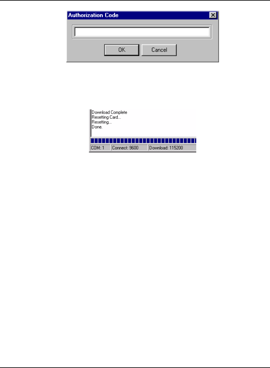
6. When the Authorization Code dialog opens, see Figure 40, enter the auth code and select OK
PC Software and Firmware Chapter 6
OEMV Family Installation and Operation User Manual Rev 5B 117
Figure 40: Authorization Code Dialog
7. The receiver should finish downloading and reset. The process is complete when “Done.” is dis-
played in the main display area, see Figure 41.
Figure 41: Upgrade Process Complete
8. Close WinLoad.
This completes the procedure required to upgrade an OEMV family receiver.

118 OEMV Family Installation and Operation User Manual Rev 5B
Chapter 7 Built-In Status Tests
7.1 Overview
The built in test monitors system performance and status to ensure the receiver is operating within its
specifications. If an exceptional condition is detected, the user is informed through one or more
indicators. The receiver status system is used to configure and monitor these indicators:
1. Receiver status word (included in the header of every message)
2. ERROR strobe signal (see Section 3.3.1, Strobes on Page 44)
3. RXSTATUSEVENT log
4. RXSTATUS log
5. Status LED
In normal operation the error strobe is driven low and the status LED on the receiver flashes green.
When an unusual and non-fatal event occurs (for example, there is no valid position solution), a bit is
set in the receiver status word. Receiver operation continues normally, the error strobe remains off,
and the LED continues to flash green. When the event ends (for example, when there is a valid
position solution), the bit in the receiver status word is cleared.
When a fatal event occurs (for example, in the event of a receiver hardware failure), a bit is set in the
receiver error word, part of the RXSTATUS log, to indicate the cause of the problem. Bit 0 is set in the
receiver status word to show that an error occurred, the error strobe is driven high, and the LED
flashes red and yellow showing an error code. An RXSTATUSEVENT log is generated on all ports to
show the cause of the error. Receiver tracking is disabled at this point but command and log
processing continues to allow you to diagnose the error. Even if the source of the error is corrected at
this point, the receiver must be reset to resume normal operation.
The above two paragraphs describe factory default behavior. Customizing is possible to better suit an
individual application. RXSTATUSEVENT logs can be disabled completely using the UNLOG
command. RXSTATUSEVENT logs can be generated when a receiver status bit is set or cleared by
using the STATUSCONFIG SET and STATUSCONFIG CLEAR commands. Bits in the receiver
status word can also be promoted to be treated just like error bits using the STATUSCONFIG
PRIORITY command.
7.2 Receiver Status Word
The receiver status word indicates the current status of the receiver. This word is found in the header
of all logs and in the RXSTATUS log. In addition the receiver status word is configurable.
The receiver gives the user the ability to determine the importance of the status bits. This is done using
the priority masks. In the case of the Receiver Status, setting a bit in the priority mask will cause the
condition to trigger an error. This will cause the receiver to idle all channels, turn off the antenna, and
disable the RF hardware, the same as if a bit in the Receiver Error word is set. Setting a bit in an
Auxiliary Status priority mask will cause that condition to set the bit in the Receiver Status word
corresponding to that Auxiliary Status.
The STATUSCONFIG command is used to configure the various status mask fields in the

Built-In Status Tests Chapter 7
OEMV Family Installation and Operation User Manual Rev 5B 119
RXSTATUSEVENT log. These masks allow you to modify whether various status fields generate
errors or event messages when they are set or cleared. This is meant to allow you to customize the
operation of your OEMV family receiver for your specific needs.
Refer to the RXSTATUS log, RXSTATUSEVENT log and STATUSCONFIG command in the OEMV
Firmware Reference Manual for more detailed descriptions of these messages.
7.3 Error Strobe Signal
The error strobe signal is one of the I/O strobes and is driven low when the receiver is operating
normally. When the receiver is in the error state and tracking is disabled, the error strobe is driven
high. This can be caused by a fatal error or by an unusual receiver status indication that the user has
promoted to be treated like a fatal error. Once on, the error status will remain high until the cause of
the error is corrected and the receiver is reset. See also Section 3.3.1, Strobes on Page 44.
7.4 RXSTATUSEVENT Log
The RXSTATUSEVENT log is used to output event messages as indicated in the RXSTATUS log.
On start-up, the OEMV family receiver is set to log the RXSTATUSEVENTA log ONNEW on all
ports. You can remove this message by using the UNLOG command.
Refer to the RXSTATUSEVENT log in the OEMV Firmware Reference Manual for a more detailed
description of this log.
7.5 RXSTATUS Log
7.5.1 Overview
The Receiver Status log (RXSTATUS) provides information on the current system status and
configuration in a series of hexadecimal words.
The status word is the third field after the header, as shown in the example below.
Figure 42: Location of Receiver Status Word
<RXSTATUS COM1 0 92.0 UNKNOWN 0 154.604 005c0020 643c 1899
< 00000000 4
< 005c0020 00000000 00000000 00000000
< 00000087 00000008 00000000 00000000
< 00000000 00000000 00000000 00000000
< 00000000 00000000 00000000 00000000
Receiver
Status
W
o
r
d
120 OEMV Family Installation and Operation User Manual Rev 5B
Chapter 7 Built-In Status Tests
Each bit in the status word indicates the status of a specific condition or function of the receiver. If the
status word is 00000000, the receiver is operating normally. The numbering of the bits is shown in
Figure 43, Reading the Bits in the Receiver Status Word on Page 120 below.
Figure 43: Reading the Bits in the Receiver Status Word
If the receiver status word indicates a problem, please also see Section 8.1, Examining the RXSTATUS
Log on Page 126.
7.5.2 Error Word
The error field contains a 32 bit word. Each bit in the word is used to indicate an error condition. Error
conditions may result in damage to the hardware or erroneous data, so the receiver is put into an error
state. If any bit in the error word is set, the receiver will set the error strobe line, flash the error code on
the status LED, broadcast the RXSTATUSEVENT log on all ports (unless the user has unlogged it),
idle all channels, turn off the antenna, and disable the RF hardware. The only way to get out of the
error state is to reset the receiver.
It is also possible to have status conditions trigger event messages to be generated by the receiver.
Receiver Error words automatically generate event messages. These event messages are output in
RXSTATUSEVENT logs (see also Section 7.5.6, Set and Clear Mask for all Status Code Arrays on
Page 122).
The error word is the first field after the log header in the RXSTATUS log, as shown in the example
below, or the third from last field in the header of every log.
Figure 44: Location of Receiver Error Word
0 0 0 4 0 0 2 8
0000 0000 0000 0100 0000 0000 0010 1000
Bit
0
Bit 31
<RXSTATUS COM1
0
92
.
0
UNKNOWN
0
154.
60
4
00
5c
0020
6
4
3
c 1
899
< 00000000 4
< 005c0020 00000000 00000000 00000000
< 00000087 00000008 00000000 00000000
< 00000000 00000000 00000000 00000000
< 00000000 00000000 00000000 00000000
Receiver
Error
W
o
r
d

Built-In Status Tests Chapter 7
OEMV Family Installation and Operation User Manual Rev 5B 121
Here is another example of a receiver error word. The numbering of the bits is shown in Figure 45.
Figure 45: Reading the Bits in the Receiver Error Word
Refer to the RXSTATUS and the RXSTATUSEVENT logs in the OEMV Firmware Reference Manual
for more detailed descriptions of these logs. If the receiver error word indicates an error, please also
see Section 8.1, Table 23, Resolving a Receiver Error Word on Page 126.
7.5.3 Status Code Arrays
There are 4 status code arrays – the receiver status word, the auxiliary 1 status, the auxiliary 2 status
and the auxiliary 3 status. Each status code array consists of 4, 32 bit words (the status word, a priority
mask, a set mask and a clear mask). The status word is similar to the error word, with each of the 32
bits indicating a condition. The mask words are used to modify the behavior caused by a change in
one of the bits in the associated status words. Each bit in any of the masks operates on the bit in the
same position in the status word. For example setting bit 3 in the priority mask changes the priority of
bit 3 in the status word.
7.5.4 Receiver Status Code
The receiver status word is included in the header of all logs. It has 32 bits, which indicate certain
receiver conditions. If any of these conditions occur, a bit in the status word is set. Unlike the error
word bits the receiver will continue to operate, unless the priority mask for the bit has been set. The
priority mask bit will change that of the receiver status word into an error bit. Anything that would
result from an error bit becoming active would also occur if a receiver status and its associated priority
mask bits are set.
7.5.5 Auxiliary Status Codes
The auxiliary status codes are only seen in the RXSTATUS log. The three arrays representing the
auxiliary status codes give indication about the receiver state for information only. The events
represented by these bits typically do not cause degradation of the receiver performance. The priority
mask for the auxiliary codes does not put the receiver into an error state. Setting a bit in the auxiliary
priority mask results in the corresponding bit in the receiver status code to be set if any masked
auxiliary bit is set. Bit 31 of the receiver status word indicates the condition of all masked bits in the
auxiliary 1 status word. Likewise, bit 30 of the receiver status word corresponds to the auxiliary 2
status word, and bit 29 to the auxiliary 3 status word.
Refer also to the RXSTATUS log in the OEMV Firmware Reference Manual for a more detailed
description of this log.
0 0 0 0 0 0 2 2
0000 0000 0000 0000 0000 0000 0010 0010
Bit
0
Bit 1
5
122 OEMV Family Installation and Operation User Manual Rev 5B
Chapter 7 Built-In Status Tests
7.5.6 Set and Clear Mask for all Status Code Arrays
The other two mask words in the status code arrays operate on the associated status word in the same
way. These mask words are used to configure which bits in the status word will result in the broadcast
of the RXSTATUSEVENT log. The set mask is used to turn logging on temporarily while the bit
changes from the 0 to 1 state. The clear mask is used to turn logging on temporarily while the bit
changes from a 1 to a 0 state. Note the error word does not have any associated mask words. Any bit
set in the error word will result in the broadcast of the RXSTATUSEVENT log (unless unlogged).
Refer also to the RXSTATUSEVENT log in the OEMV Firmware Reference Manual for a more
detailed description.
7.6 Status LEDs
7.6.1 OEMV Cards
The diagnostic LED provided on the OEMV family cards blinks green on and off at approximately 1
Hz to indicate normal operation.
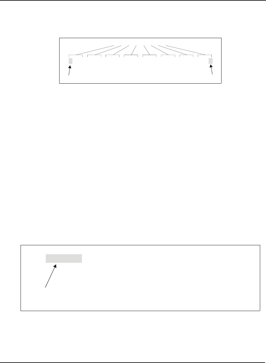
Error bits and status bits that have been priority masked, as errors, will cause the LED to flash a code
in a binary sequence. The binary sequence will be a 6 flash (0.5 second on and 0.25 second off per
flash) sequence followed by a 1 second delay. The sequence will repeat indefinitely. If there is more
than one error or status present, the lowest number will be output. The codes are ordered to have the
highest priority condition output first.
The first flash in the 6 flash sequence indicates if the code that follows is an error bit or a status bit.
Error bits will flash red and status bits will flash yellow. The next 5 flashes will be the binary number
of the code (most significant bit first). A red flash indicates a one and a yellow flash indicates a zero.
For example, for an error bit 6, the binary number is 00110 so the output sequence would be:
followed by a 1 second delay. The sequence repeats indefinitely until the receiver is reset.
In the example on Page 123, the first flash in the sequence is red, which means that a bit is set in the
receiver error word. The next five flashes give a binary value of 00111. Converting this value to
decimal results in a value of 7. Therefore, bit 7 of the receiver error word is set, indicating there is a
problem with the supply voltage of the receiver’s power circuitry.
0 0.5 0.75 1.25 1.50 2.0 2.25 2.75 3.0 3.5 3.75 4.25 5.25
Red Yellow Yellow Red Red Yellow
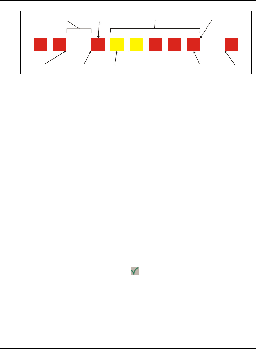
Built-In Status Tests Chapter 7
OEMV Family Installation and Operation User Manual Rev 5B 123
Figure 46: Status LED Flash Sequence Example
Reference Description
1Red
2 Yellow
3 1 Second Pause
4 Word Identifier Flash
5 Bit Identifier Flashes
6 End of Sequence
7 End of Previous Sequence
8 Beginning of Sequence
9 Most Significant Bit of Binary Value
10 Least Significant Bit of Binary Value
11 Start of Next Sequence
For a complete hexadecimal to binary conversion list, refer to the Unit Conversion section of the
GPS+ Reference Manual. Refer also to the RXSTATUS log, and its tables for more details on this log
and receiver error status.
7.6.2 DL-V3 Enclosure
The status LED on the front of DL-V3, with the icon, is described in Section 3.3.5, DL-V3 Status
Indicators on Page 48.
..
.
...
111221111
34
5
6
78910 11

124 OEMV Family Installation and Operation User Manual Rev 5B
Chapter 8 Troubleshooting
When your receiver appears not to be working properly, often there are simple ways to diagnose and
resolve the problem. In many cases, the issue can be resolved within a few minutes, avoiding the
hassle and loss of productivity that results from having to return your receiver for repair. This chapter
is designed to assist you in troubleshooting problems that occur and includes navigational instructions
to bring you to the part of this manual that details resolutions to aid your receiver’s operation.
If you are unsure of the symptoms or if the symptoms do not match any of those listed, use the
RXSTATUS log to check the receiver status and error words. See Section 8.1, Examining the
RXSTATUS Log, Page 126.
If the problem is not resolved after using this troubleshooting guide, contact NovAtel Customer
Service, see Page 18.
Table 22: Troubleshooting based on Symptoms
Symptom Related Section
The receiver is not properly powered Check for and switch a faulty power cable.
See Section 3.1.3, Power Supply Requirements,
Page 34 and Section 3.3.3, CAN Bus, Page 46.
The receiver cannot establish communication Check for and switch faulty serial cables and ports.
See Section 3.3.3, CAN Bus, Page 46 and
Section 7.6, Status LEDs, Page 122. Refer also to
the COMCONFIG log in the OEMV Firmware
Reference Manual.
The receiver is not tracking satellites Ensure you have an unobstructed view of the sky
from horizon to horizon.
Check for and replace a faulty antenna cable.
See Section 3.1.1, Selecting a GNSS Antenna,
Page 33, Section 3.1.2, Choosing a Coaxial Cable,
Page 34, Section 3.2.4, Connecting the Antenna to
the Receiver, Page 40, Section 3.3.7, Antenna
LNA Power, Page 51 and refer to the Time to
First Fix and Satellite Acquisition section of the
GPS+ Reference Manual.
No data is being logged See Section 3.3.3, CAN Bus, Page 46, and
Section 4.1, Communications with the Receiver,
Page 57.
Random data is being output by the receiver,
or binary data is streaming
Check the baud rate on the receiver and in the
communication software. Refer to the
COMCONFIG log and FRESET command in the
OEMV Firmware Manual.
See also Section 3.3.3, CAN Bus, Page 46.
Continued on Page 125

Troubleshooting Chapter 8
OEMV Family Installation and Operation User Manual Rev 5B 125
Symptom Related Section
A command is not accepted by the receiver Check for correct spelling and command syntax.
See Section 4.1, Communications with the
Receiver, Page 57 and refer to the FRESET
command in the OEMV Firmware Reference
Manual.
Differential mode is not working properly See Section 4.3, Transmitting and Receiving
Corrections, Page 60 and refer to the
COMCONFIG log in the OEMV Firmware
Reference Manual.
There appears to be a problem with the
receiver’s memory Refer to the NVMRESTORE command in the
OEMV Firmware Reference Manual.
An environmental or memory failure. The
receiver temperature is out of acceptable
range or the internal thermometer is not
working
See the ENVIRONMENTAL sections in the tables
of Appendix A, Technical Specifications starting on
Page 129.
Move the receiver to within an acceptable
temperature range or increase the baud rate.
Overload and overrun problems. Either the
CPU or port buffers are overloaded Reduce the amount of logging. See also Section
4.1.1, Serial Port Default Settings, Page 57.
The receiver is indicating that an invalid
authorization code has been used
Refer to the Version log, VALIDMODELS log and
the MODEL command in the OEMV Firmware
Reference Manual.
The receiver is being affected by jamming Move the receiver away from any possible
jamming sources.
The receiver’s automatic gain control (AGC)
is not working properly
See Section 3.1.2, Choosing a Coaxial Cable,
Page 34 and the jamming symptom in this table.

126 OEMV Family Installation and Operation User Manual Rev 5B
Chapter 8 Troubleshooting
8.1 Examining the RXSTATUS Log
The RXSTATUS log provides detailed status information about your receiver and can be used to
diagnose problems. Please refer to the OEMV Firmware Reference Manual for details on this log and
on how to read the receiver error word and status word. Tables 23 and 24 on pages 126 to 128 give
you actions to take when your receiver has an error flag in either of these words.
Table 23: Resolving a Receiver Error Word
Bit Set Action to Resolve
0 Issue a FRESET command
1 Issue a FRESET command
2 Issue a FRESET command
4 Contact Customer Service as described on Page 18
5 Check the VERSION log
6 Issue a FRESET command
7 See Section 3.1.3, Power Supply Requirements, Page 34
8 Issue a NVMRESTORE command
9 Check temperature ranges in the ENVIRONMENTAL table
sections of Appendix A, Technical Specifications starting on
Page 129
10 Contact Customer Service as described on Page 18
11
12
13
14
15 Move the receiver away from any possible jamming sources

Troubleshooting Chapter 8
OEMV Family Installation and Operation User Manual Rev 5B 127
Table 24: Resolving an Error in the Receiver Status Word
Bit Set Action to Resolve
0 Check the Error Word in the RXSTATUS log. See also Table 23, Resolving a
Receiver Error Word on Page 126.
1 Check temperature ranges in the ENVIRONMENTAL table sections of
Appendix A, , Technical Specifications starting on Page 129.
2 See Section 3.1.3, Power Supply Requirements, Page 34.
3 See Section 3.1.1, Selecting a GNSS Antenna, Page 33, Section 3.1.2,
Choosing a Coaxial Cable, Page 34, Section 3.2.4, Connecting the Antenna to
the Receiver, Page 40, Section 3.3.7, Antenna LNA Power, Page 51 and refer
to the Time to First Fix and Satellite Acquisition section of the GPS+
Reference Manual.
4
5
6
7 See Section 4.1.1, Serial Port Default Settings, Page 57.
8
9
10
11
14 Move the receiver away from any possible jamming sources.
15 See Section 3.1.2, Choosing a Coaxial Cable, Page 34 and move the receiver
away from any possible jamming sources.
16 Move the receiver away from any possible jamming sources.
17 See Section 3.1.2, Choosing a Coaxial Cable, Page 34 and move the receiver
away from any possible jamming sources.
18 None. Once enough time has passed for a valid almanac to be received, this bit
will be set to 0. Also, refer to the Time to First Fix and Satellite Acquisition
section of the GPS+ Reference Manual.
19 None. This bit only indicates if the receiver has calculated a position yet. Refer
to the Time to First Fix and Satellite Acquisition section of the GPS+
Reference Manual
20 None. This bit is simply a status bit indicating if the receiver’s position has been
manually fixed and does not represent a problem. Refer also to the FIX
command in the OEMV Firmware Reference Manual.
Continued on Page 128

128 OEMV Family Installation and Operation User Manual Rev 5B
Chapter 8 Troubleshooting
Bit Set Action to Resolve
21 None. This bit simply indicates if clock steering has been manually disabled.
Refer also to the FRESET command in the OEMV Firmware Reference Manual.
22 None. This bit only indicates if the clock model is valid. Refer also to the
FRESET command in the OEMV Firmware Reference Manual.
23 None. This bit indicates whether or not the phase-lock-loop is locked when using
an external oscillator. Refer also to the FRESET command in the OEMV
Firmware Reference Manual.
30 None. This bit indicates if any bits in the auxiliary 2 status word are set. The
auxiliary 2 word simply provides status information and does not provide any
new information on problems. Refer also to the FRESET command in the OEMV
Firmware Reference Manual.
31 None. This bit indicates if any bits in the auxiliary 1 status word are set. The
auxiliary 1 word simply provides status information and does not provide any
new information on problems.Refer also to the FRESET command in the OEMV
Firmware Reference Manual.

OEMV Family Installation and Operation User Manual Rev 5B 129
Appendix A Technical Specifications
A.1 OEMV Family Receiver Performance
PERFORMANCE (Subject To GPS System Characteristics)
Position Accuracy aStandalone:
L1 only 1.8 m RMS
L1/L2 1.5 m RMS
WAAS:
L1 only 1.2 m RMS
L1/L2 0.9 m RMS
DGPS 0.45 m RMS
RT-20 0.20 m RMS
RT-2 0.01 m + 1 ppm RMS
CDGPS: 1.0 m RMS (OEMV-1 and OEMV-3 only)
OmniSTAR:
VBS 0.7 m RMS (OEMV-1 and OEMV-3 only)
XP 0.15 m RMS (OEMV-3 only)
HP 0.10 m RMS (OEMV-3 only)
Post Processed 5 mm + 1 ppm RMS
Time To First Fix Hot: 30 s (Almanac and recent ephemeris saved and approximate position)
Warm: 40 s (Almanac, approximate position and time, no recent ephemeris)
Cold: 50 s (No almanac or ephemeris and no approximate position or time)
Reacquisition 0.5 s L1 (typical)
1.0 s L2 (typical) (OEMV-2 and OEMV-3 only)
Data Rates Raw
Measurements: 20 Hz
Computed
Position: 20 Hz
OmniSTAR HP
Position: 20 Hz (OEMV-3 only)
Time Accuracy a b 20 ns RMS
Velocity Accuracy 0.03 m/s RMS
Measurement Precision C/A code phase 6 cm RMS
L1 carrier phase:
Differential 0.75 mm RMS
L2 P code 25 cm RMS (OEMV-2 and OEMV-3 only)
L2 carrier phase:
Differential 2 mm RMS (OEMV-2 and OEMV-3 only)
Dynamics
Velocity 515 m/s c
Height 18,288 m
c
a. Typical values. Performance specifications are subject to GPS system characteristics, U.S. DOD operational degradation,
ionospheric and tropospheric conditions, satellite geometry, baseline length and multipath effects.
b. Time accuracy does not include biases due to RF or antenna delay.
c. In accordance with ex
p
ort licensin
g
.
130 OEMV Family Installation and Operation User Manual Rev 5B
Appendix A Technical Specifications
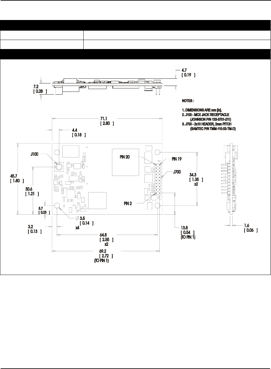
A.2 OEMV-1 Card
PHYSICAL
Size 46 mm x 71 mm x 10.3 mm with connectors
Weight 21.5 grams
MECHANICAL DRAWINGS
Figure 47: OEMV-1 Board Dimensions

Technical Specifications Appendix A
OEMV Family Installation and Operation User Manual Rev 5B 131
ENVIRONMENTAL
Operating Temperature -40°C to +85°C
Storage Temperature -45°C to +95°C
Humidity Not to exceed 95% non-condensing
Random Vibe RTCA D0-160D (4g)
Bump/Shock MIL-STD 810F (40g)
POWER REQUIREMENTS
Voltage +3.3 V DC +5%/-3%
Allowable Input Voltage Ripple 100 mV p-p (max.)
Power consumption 1.1 W (typical, GPS only)
1.6 W (typical, GPS and L-Band)
RF INPUT / LNA POWER OUTPUT
Antenna Connector MCX female, 50 Ω nominal impedance (See Figure 47 on Page 130)
Acceptable RF Input Level -80 to -105 dBm
RF Input Frequencies GPS L1: 1575.42 MHz
OmniSTAR
or CDGPS: 1525 to 1560 MHz
LNA Power
External (Optional Input)
Output to antenna
(See also Section 2.3.1 on Page 32)
+5.5 to +16 V DC, 100 mA max. (user-supplied)
+4.75 to +5.10 V DC @ 0 - 100 mA
INPUT/OUTPUT DATA INTERFACE
COM1
Electrical format LVTTL
Bit rates a300, 1200, 4800, 9600 (default), 19200, 38400, 57600, 115200,
230400, 460800, 921600 bps
Signals supported COM1_Tx and COM1_Rx
COM2
Electrical format LVTTL
Bit rates a300, 1200, 4800, 9600 (default), 19200, 38400, 57600, 115200,
230400, 921600 bps
Signals supported COM2_Tx and COM2_Rx
COM3
Electrical format LVTTL b c d
Bit rates a300, 1200, 4800, 9600 (default), 19200, 38400, 57600, 115200,
230400 bps
Signals supported COM3_Tx and COM3_Rx
Continued on Page 132

132 OEMV Family Installation and Operation User Manual Rev 5B
Appendix A Technical Specifications
CAN BUS ef gE F
Electrical format LVTTL (requires external CAN transceiver)
Bit rates 500 kb/s maximum. CAN Bus throughput is determined by slowest
device on the bus.
Signals supported CAN1 is on Pins 6 and 7. CAN2 is on Pins 8 and 20. g
USB
Electrical format Conforms to USB 1.1
Bit rates 5 Mb/s maximum
Signals supported USB D (+) and USB D (-)
a. Baud rates higher than 115,200 bps are not supported by standard PC hardware. Special PC
hardware may be required for higher rates, including 230400 bps, 460800 bps, and 921600 bps.
b. Upon power-up, USB is enabled and COM3 is disabled by default. COM3_Tx and COM3_Rx
are multiplexed with USB D (+) and EVENT1, respectively.
c. The receiver cannot prevent the host system from enumerating USB while using COM3 on the
OEMV-1. This is due to the plug-and-play nature of USB. Do not connect a USB cable while
using COM3.
d. Enable COM3 using the INTERFACEMODE command.
e. CAN1_RX and CAN1_TX are multiplexed with VARF and EVENT2, respectively. The default
behavior is that EVENT2 is active. For VARF, refer to the FREQUENCYOUT command.
f. CAN Bus behavior must be asserted through the NovAtel API software. See Section 3.3.3, CAN
Bus on Page 46 for further details.
g. See also Figure 48 on Page 135 and its table.

Technical Specifications Appendix A
OEMV Family Installation and Operation User Manual Rev 5B 133
Table 25: OEMV-1 Strobes
Strobes Default
Behavior Input/
Output Factory Default Comment a
Event1 (Mark 1) Multiplexed pin
with COM3
Input
Leading
edge
triggered
Active low An input mark for which a pulse
greater than 150 ns triggers certain
logs to be generated. (Refer to the
MARKPOS and MARKTIME logs
and ONMARK trigger.) Polarity is
configurable using the
MARKCONTROL command. The
mark inputs have 10K pull-up
resistors to 3.3 V
Event2 (Mark 2) Multiplexed pin Input
Leading
edge
triggered
Active low An input mark for which a pulse
greater than 150 ns triggers certain
logs to be generated. (Refer to the
MARK2POS and MARK2TIME
logs.) Polarity is configurable using
the MARKCONTROL command.
The mark inputs have 10K pull-up
resistors to 3.3 V.
PV (Position
Valid) Dedicated pin Output Active high Indicates a valid GPS position
solution is available. A high level
indicates a valid solution or that the
FIX POSITION command has been
set (refer to the FIX POSITION
command). VDD is 3.3V.
VARF (Variable
Frequency) Multiplexed pin Output Active low A programmable variable
frequency output ranging from 0 -
20 MHz (refer to the
FREQUENCYOUT command).
RESETIN Dedicated pin Input Active low Reset LVTTL signal input from
external system; active low, > 20 µs
duration
TIMEMARK Dedicated pin Output Active low A time synchronization output. This
is a pulse where the leading edge is
synchronized to receiver-
calculated GPS Time. The polarity,
period and pulsewidth can be
configured using PPSCONTROL
command.
a. The commands and logs shown in capital letters (for example, MARKCONTROL) are
discussed in further detail in the OEMV Family Firmware Reference Manual.

134 OEMV Family Installation and Operation User Manual Rev 5B
Appendix A Technical Specifications
Table 26: OEMV-1 Strobe Electrical Specifications
Strobe Sym Min Typ Max Units Conditions
Event1 (Mark 1)
Event2 (Mark2)
TIMEMARK
VIL 0.8 V VDD = 3.3 V; 85°C
VIH 2.0 V VDD = 3.3 V; 85°C
PV
VARF
VOL 0.4 V VDD = 3.3 V; 85°C
VOH 3.0 V VDD = 3.3 V; 85°C
RESETIN
VIL 0.8 V VDD = 3.3 V; 85°C
VIH 2.3 V VDD = 3.3 V; 85°C

Technical Specifications Appendix A
OEMV Family Installation and Operation User Manual Rev 5B 135
Figure 48: Top-view of 20-Pin Connector on the OEMV-1
Signal Behavior aDescriptions Pin
LNA_PWR Input DC Power supply for external antenna LNA 1
VIN Input DC DC power supply for card 2
USB D (-) Bi-directional USB interface data (-) 3
USB D (+) /
COM3_Rx Multiplexed Multiplexed pin behavior
default: USB D (+)
4
RESETIN See strobes Card reset 5
VARF / CAN1_Rx Multiplexed Multiplexed pin behavior, see strobes
default: VARF
6
Event2 / CAN1_Tx Multiplexed Multiplexed pin behavior, see strobes
default: Event2
7
CAN2_RX Bi-directional CAN Bus dedicated port 8
Event1 / COM3_Tx Multiplexed Multiplexed pin behavior, see strobes
default: Event1
9
GND Ground Digital Ground 10
COM1_Tx Output Transmitted Data for COM 1 output 11
COM1_Rx Input Received Data for COM 1 input 12
GND Ground Digital Ground 13
COM2_Tx Output Transmitted Data for COM 2 output 14
COM2_Rx Input Received Data for COM 2 input 15
GND Ground Digital Ground 16
PV See strobes Output indicates 'good solution' or valid GPS position
when high 17
GND Ground Digital Ground 18
TIMEMARK See strobes Pulse output synchronized to GPS Time 19
CAN2_TX Bi-directional CAN Bus dedicated port 20
a. A bi-directional Transient Voltage Suppressor (TVS) device is included between 3.3V and
ground. Input/Output (I/O) lines are protected by TVS devices. Series resistance is included
for the following I/O lines: COM1/COM2/COM3 Tx and Rx, RESETIN, Event1 and
Event2. Lines that do not have series resistance include: CAN1_Tx, CAN1_Rx, CAN2_Tx,
CAN2_Rx, USB D (+) and USB D (-).
Pin 1
Pin 19
Pin 2
0
Pin 2
136 OEMV Family Installation and Operation User Manual Rev 5B
Appendix A Technical Specifications
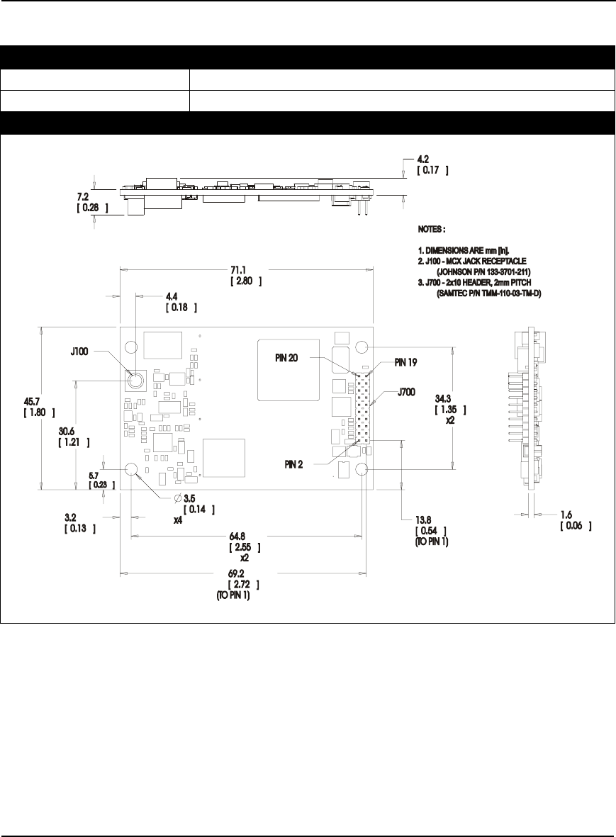
A.3 OEMV-1G Card
PHYSICAL
Size 46 mm x 71 mm x 9.8 mm with connectors
Weight 21.5 grams
MECHANICAL DRAWINGS
Figure 49: OEMV-1G Board Dimensions

Technical Specifications Appendix A
OEMV Family Installation and Operation User Manual Rev 5B 137
ENVIRONMENTAL
Operating Temperature -40°C to +85°C
Storage Temperature -45°C to +95°C
Humidity Not to exceed 95% non-condensing
Random Vibe RTCA D0-160D (4g)
Bump/Shock MIL-STD 810F (40g)
POWER REQUIREMENTS
Voltage +3.3 V DC +5%/-3%
Allowable Input Voltage Ripple 100 mV p-p (max.)
Power consumption 1.1 W (typical, GPS and GLONASS)
RF INPUT / LNA POWER OUTPUT
Antenna Connector MCX female, 50 Ω nominal impedance (See Figure 49 on Page 136)
Acceptable RF Input Level -80 to -105 dBm
RF Input Frequencies GPS L1: 1575.42 MHz
GLONASS L1: 1602.0 MHz for Fk=0 where k = (-7 to +13)
Channel spacing 562.5 kHz
LNA Power
External (Optional Input)
Output to antenna
(See also Section 2.3.1 on Page 32)
+5.5 to +16 V DC, 100 mA max. (user-supplied)
+4.75 to +5.10 V DC @ 0 - 100 mA
INPUT/OUTPUT DATA INTERFACE
COM1
Electrical format LVTTL
Bit rates a300, 1200, 4800, 9600 (default), 19200, 38400, 57600, 115200,
230400, 460800, 921600 bps
Signals supported COM1_Tx and COM1_Rx
COM2
Electrical format LVTTL
Bit rates a300, 1200, 4800, 9600 (default), 19200, 38400, 57600, 115200,
230400, 921600 bps
Signals supported COM2_Tx and COM2_Rx
COM3
Electrical format LVTTL b c d
Bit rates a300, 1200, 4800, 9600 (default), 19200, 38400, 57600, 115200,
230400 bps
Signals supported COM3_Tx and COM3_Rx
Continued on Page 132
CAN BUS ef gE F

138 OEMV Family Installation and Operation User Manual Rev 5B
Appendix A Technical Specifications
Electrical format LVTTL (requires external CAN transceiver)
Bit rates 500 kb/s maximum. CAN Bus throughput is determined by slowest
device on the bus.
Signals supported CAN1 is on Pins 6 and 7. CAN2 is on Pins 8 and 20. g
USB
Electrical format Conforms to USB 1.1
Bit rates 5 Mb/s maximum
Signals supported USB D (+) and USB D (-)
a. Baud rates higher than 115,200 bps are not supported by standard PC hardware. Special PC
hardware may be required for higher rates, including 230400 bps, 460800 bps, and 921600 bps.
b. Upon power-up, USB is enabled and COM3 is disabled by default. COM3_Tx and COM3_Rx
are multiplexed with USB D (+) and EVENT1, respectively.
c. The receiver cannot prevent the host system from enumerating USB while using COM3 on the
OEMV-1G. This is due to the plug-and-play nature of USB. Do not connect a USB cable while
using COM3.
d. Enable COM3 using the INTERFACEMODE command.
e. CAN1_RX and CAN1_TX are multiplexed with VARF and EVENT2, respectively. The default
behavior is that EVENT2 is active. For VARF, refer to the FREQUENCYOUT command.
f. CAN Bus behavior must be asserted through the NovAtel API software. See Section 3.3.3, CAN
Bus on Page 46 for further details.
g. See also Figure 50 on Page 141 and its table.

Technical Specifications Appendix A
OEMV Family Installation and Operation User Manual Rev 5B 139
Table 27: OEMV-1G Strobes
Strobes Default
Behavior Input/
Output Factory Default Comment a
Event1 (Mark 1) Multiplexed pin
with COM3
Input
Leading
edge
triggered
Active low An input mark for which a pulse
greater than 150 ns triggers certain
logs to be generated. (Refer to the
MARKPOS and MARKTIME logs
and ONMARK trigger.) Polarity is
configurable using the
MARKCONTROL command. The
mark inputs have 10K pull-up
resistors to 3.3 V
Event2 (Mark 2) Multiplexed pin Input
Leading
edge
triggered
Active low An input mark for which a pulse
greater than 150 ns triggers certain
logs to be generated. (Refer to the
MARK2POS and MARK2TIME
logs.) Polarity is configurable using
the MARKCONTROL command.
The mark inputs have 10K pull-up
resistors to 3.3 V.
PV (Position
Valid) Dedicated pin Output Active high Indicates a valid GPS position
solution is available. A high level
indicates a valid solution or that the
FIX POSITION command has been
set (refer to the FIX POSITION
command). 3.3 V.
VARF (Variable
Frequency) Multiplexed pin Output Active low A programmable variable
frequency output ranging from 0 -
20 MHz (refer to the
FREQUENCYOUT command).
RESETIN Dedicated pin Input Active low Reset LVTTL signal input from
external system; active low, > 20 µs
duration
TIMEMARK Dedicated pin Output Active low A time synchronization output. This
is a pulse where the leading edge is
synchronized to receiver-
calculated GPS Time. The polarity,
period and pulsewidth can be
configured using PPSCONTROL
command.
a. The commands and logs shown in capital letters (for example, MARKCONTROL) are
discussed in further detail in the OEMV Family Firmware Reference Manual.

140 OEMV Family Installation and Operation User Manual Rev 5B
Appendix A Technical Specifications
Table 28: OEMV-1G Strobe Electrical Specifications
Strobe Sym Min Typ Max Units Conditions
Event1 (Mark 1)
Event2 (Mark2)
TIMEMARK
VIL 0.8 V VDD = 3.3 V; 85°C
VIH 2.0 V VDD = 3.3 V; 85°C
PV
VARF
VOL 0.4 V VDD = 3.3 V; 85°C
VOH 3.0 V VDD = 3.3 V; 85°C
RESETIN
VIL 0.8 V VDD = 3.3 V; 85°C
VIH 2.3 V VDD = 3.3 V; 85°C

Technical Specifications Appendix A
OEMV Family Installation and Operation User Manual Rev 5B 141
Figure 50: Top-view of 20-Pin Connector on the OEMV-1G
Signal Behavior aDescriptions Pin
LNA_PWR Input DC Power supply for external antenna LNA 1
VIN Input DC DC power supply for card 2
USB D (-) Bi-directional USB interface data (-) 3
USB D (+) /
COM3_Rx Multiplexed Multiplexed pin behavior
default: USB D (+)
4
RESETIN See strobes Card reset 5
VARF / CAN1_Rx Multiplexed Multiplexed pin behavior, see strobes
default: VARF
6
Event2 / CAN1_Tx Multiplexed Multiplexed pin behavior, see strobes
default: Event2
7
CAN2_RX Bi-directional CAN Bus dedicated port 8
Event1 / COM3_Tx Multiplexed Multiplexed pin behavior, see strobes
default: Event1
9
GND Ground Digital Ground 10
COM1_Tx Output Transmitted Data for COM 1 output 11
COM1_Rx Input Received Data for COM 1 input 12
GND Ground Digital Ground 13
COM2_Tx Output Transmitted Data for COM 2 output 14
COM2_Rx Input Received Data for COM 2 input 15
GND Ground Digital Ground 16
PV See strobes Output indicates 'good solution' or valid GPS position
when high 17
GND Ground Digital Ground 18
TIMEMARK See strobes Pulse output synchronized to GPS Time 19
CAN2_TX Bi-directional CAN Bus dedicated port 20
a. A bi-directional Transient Voltage Suppressor (TVS) device is included between 3.3V and
ground. Input/Output (I/O) lines are protected by TVS devices. Series resistance is included
for the following I/O lines: COM1/COM2/COM3 Tx and Rx, RESETIN, Event1 and
Event2. Lines that do not have series resistance include: CAN1_Tx, CAN1_Rx, CAN2_Tx,
CAN2_Rx, USB D (+) and USB D (-).
Pin 1
Pin 19
Pin 2
0
Pin 2
142 OEMV Family Installation and Operation User Manual Rev 5B
Appendix A Technical Specifications
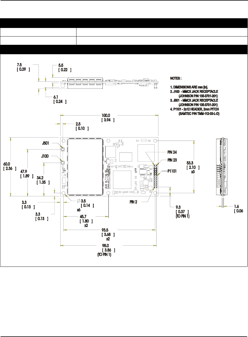
A.4 OEMV-2 Card
PHYSICAL
Size 60 mm x 100 mm x 11.4 mm with connectors
Weight 56 grams
MECHANICAL DRAWINGS
Figure 51: OEMV-2 Board Dimensions

Technical Specifications Appendix A
OEMV Family Installation and Operation User Manual Rev 5B 143
ENVIRONMENTAL
Operating Temperature -40°C to +85°C
Storage Temperature -45°C to +95°C
Humidity Not to exceed 95% non-condensing
Random Vibe MIL-STD 810F (7.7g)
Sine Vibe SAEJ1211 (4g)
Bump/Shock IEC 68-2-27 (30g)
POWER REQUIREMENTS
Voltage +3.3 V DC +5%/-3%
Allowable Input Voltage Ripple 100 mV p-p (max.)
Power consumption 1.2 W (typical, GPS only)
1.6 W (typical, GPS and GLONASS)
RF INPUT / LNA POWER OUTPUT
Antenna Connector MMCX female, 50 Ω nominal impedance (See Figure 51 on Page 142)
Acceptable RF Input Level -80 dBm to -105 dBm
RF Input Frequencies GPS L1: 1575.42 MHz
GPS L2: 1227.60 MHz
GLONASS L1: 1602.0 MHz for Fk=0 where k = (-7 to +13)
Channel spacing 562.5 kHz
GLONASS L2: 1246.0 MHz for Fk=0 where k= (-7 to +13)
Channel spacing 437.5 kHz
LNA Power
Internal
(See Section 2.3.1 on Page 32)
+4.75 to +5.10 V DC @ 0 - 100 mA (output from card; only option)
EXTERNAL OSCILLATOR INPUT
Connector MMCX female (See Figure 53 on Page 148)
Connections between the MMCX and an external oscillator, or
interface board, must be impedance controlled. To accomplish this,
use 50 ohm coaxial cable and 50 ohm connectors.
External Clock Input (Refer to the
EXTERNALCLOCK command) Frequency: 5 MHz or 10 MHz
Input Impedance: 50 Ω nominal
Input VSWR: < 2.0 : 1
Signal Level: 0 dBm minimum to +13.0 dBm maximum
Frequency Stability: ± 0.5 ppm maximum
Wave Shape: Sinusoidal

144 OEMV Family Installation and Operation User Manual Rev 5B
Appendix A Technical Specifications
INPUT/OUTPUT DATA INTERFACE
COM1
Electrical format RS-232
Bit rates a300, 1200, 4800, 9600 (default), 19200, 38400, 57600, 115200, 230400,
460800, 921600 bps
Signals supported COM1_Tx, COM1_Rx, RTS1, CTS1
COM2
Electrical format LVTTL
Bit rates a300, 1200, 4800, 9600 (default), 19200, 38400, 57600, 115200, 230400 bps
Signals supported COM2_Tx, COM2_Rx, RTS2, CTS2
COM3
Electrical format LVTTL b c d
Bit rates a300, 1200, 4800, 9600 (default), 19200, 38400, 57600, 115200, 230400 bps
Signals supported COM3_Tx, COM3_Rx
CAN BUS eE
Electrical format LVTTL b (requires external CAN transceiver)
Bit rates 500 kb/s maximum. CAN Bus throughput is determined by slowest device on
the bus.
Signals supported CAN1 is on Pins 7 and 19 f g
USB
Electrical format Conforms to USB 1.1
Bit rates 5 Mb/s maximum
a. Baud rates higher than 115,200 bps are not supported by standard PC hardware. Special PC
hardware may be required for higher rates, including 230400 bps, 460800 bps, and 921600 bps.
b. COM3 is the default. COM3_Tx and COM3_Rx are multiplexed with CAN1_Tx and GPIO,
AND CAN1_Rx AND EVENT2.
c. Upon power-up, COM3 (COM3_Tx and COM3_Rx) is enabled by default unless the default is
overridden by a changed configuration, previously saved using the SAVECONFIG command.
When COM3 is enabled, CAN1, GPIO0 and EVENT2 are not available. USB is always
available.
d. Enable COM3 using the INTERFACEMODE command. GPIO on Pin 19 is configured by the
MARKCONTROL command.
e. CAN Bus behavior must be asserted through the NovAtel API software. See Section 3.3.3, CAN
Bus on Page 46 for further details.
f. See also Figure 52 on Page 147 and its table.
g. Driven by an open collector source when configured as GPIO

Technical Specifications Appendix A
OEMV Family Installation and Operation User Manual Rev 5B 145
Table 29: OEMV-2 Strobes
Strobes Default
Behavior Input/
Output Factory Default Comment a
Event1 (Mark 1) Dedicated pin Input
Leading
edge
triggered
Active low An input mark for which a pulse
greater than 150 ns triggers certain
logs to be generated. (Refer to the
MARKPOS and MARKTIME logs
and ONMARK trigger. Polarity is
configurable using the
MARKCONTROL command. The
mark inputs have 10K pull-up
resistors to 3.3 V
Event2 (Mark 2) Multiplexed pin Input
Leading
edge
triggered
Active low An input mark for which a pulse
greater than 150 ns triggers certain
logs to be generated. (Refer to the
MARK2POS and MARK2TIME
logs. Polarity is configurable using
the MARKCONTROL command.
The mark inputs have 10K pull-up
resistors to 3.3 V.
PV (Position
Valid) Dedicated pin Output Active high Indicates a valid GPS position
solution is available. A high level
indicates a valid solution or that the
FIX POSITION command has been
set (refer to the FIX POSITION
command).
VARF (Variable
Frequency) Dedicated pin Output Active low A programmable variable
frequency output ranging from 0 -
20 MHz (refer to the
FREQUENCYOUT command).
RESETIN Dedicated pin Input Active low Reset LVTTL signal input from
external system; active low, > 20 µs
duration
PPS Dedicated pin Output Active low A time synchronization output. This
is a pulse where the leading edge is
synchronized to receiver-
calculated GPS Time. The polarity,
period and pulsewidth can be
configured using PPSCONTROL
command.
ERROR Dedicated pin Output Active high See Chapter 7, Built-In Status
Tests starting on Page 118
a. The commands and logs shown in capital letters (for example, MARKCONTROL) are
discussed in further detail in the OEMV Family Firmware Reference Manual.

146 OEMV Family Installation and Operation User Manual Rev 5B
Appendix A Technical Specifications
Table 30: OEMV-2 Strobe Specifications
Strobe Sym Min Typ Max Units Conditions
Event1 (Mark 1)
Event2 (Mark2)
PPS
VIL 0.8 V VDD = 3.3 V; 85°C
VIH 2.0 V VDD = 3.3 V; 85°C
PV
VARF
ERROR
VOL 0.4 V VDD = 3.3 V; 85°C
VOH 3.0 V VDD = 3.3 V; 85°C
RESETIN
VIL 0.8 V VDD = 3.3 V; 85°C
VIH 2.3 V VDD = 3.3 V; 85°C

Technical Specifications Appendix A
OEMV Family Installation and Operation User Manual Rev 5B 147
Figure 52: Top-view of 24-Pin Connector on the OEMV-2
Signal Behavior a
a. There is no TVS between 3.3 V and ground. All other I/O signal lines have TVS protection.
Series resistance is included for the GPIO0 and RESETIN lines.
Descriptions Pin
GND Ground Digital ground 1
GPIO_USER1 Reserved Do not use 2
VARF0 See strobes Variable frequency out 3
PPS See strobes Pulse output synchronized to GPS Time 4
VCC Input DC Card power 5
VCC Input DC Card power 6
Event2, CAN1_Rx
and COM3_Rx Multiplexed Multiplexed pin behavior, see strobes
default: COM3_Rx
7
Event1 See strobes Input trigger 8
ERROR See strobes Card error, see Chapter 7, Built-In Status Tests
starting on Page 118 9
PV See strobes Output indicates valid GPS position when high 10
CTS2/VARF1 Input Clear to Send for COM 2 input or variable frequency
default: CTS2
11
RESETIN See strobes Card reset 12
RTS2 Output Request to Send for COM 2 output 13
COM2_Rx Input Received Data for COM 2 input 14
CTS1 Input Clear to Send for COM 1 input 15
COM2_Tx Output Transmitted Data for COM 2 output 16
RTS1 Output Request to Send for COM 1 output 17
COM1_Rx Input Received Data for COM 1 input 18
GPIO0, CAN1_Tx
and COM3_Tx Multiplexed Multiplexed pin behavior, see strobes
default: COM3_Tx
19
COM1_Tx Output Transmitted Data for COM 1 output 20
USB D (-) Bi-directional USB interface data (-) 21
USB D (+) Bi-directional USB interface data (+) 22
GND Ground Digital Ground 23
GND Ground Digital Ground 24
1
2
3
4
5
6
7
8
9
10
11
12
13
14
15
16
17
18
19
20
21
22
23
24
148 OEMV Family Installation and Operation User Manual Rev 5B
Appendix A Technical Specifications
A.5 OEMV-3 Card
PHYSICAL
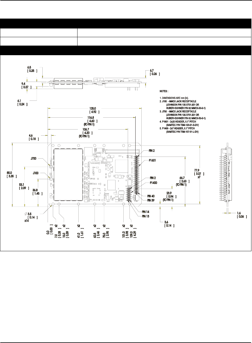
Size 85 mm x 125 mm x 14.3 mm with connectors
Weight 85 grams
MECHANICAL DRAWINGS
Figure 53: OEMV-3 Board Dimensions

Technical Specifications Appendix A
OEMV Family Installation and Operation User Manual Rev 5B 149
ENVIRONMENTAL
Operating Temperature -40°C to +85°C
Storage Temperature -45°C to +95°C
Humidity Not to exceed 95% non-condensing
Random Vibe MIL-STD 810F (7.7g)
Sine Vibe SAEJ1211 (4g)
Bump/Shock IEC 68-2-27 (30g)
POWER REQUIREMENTS
Voltage +4.5 to +18.0 V DC
Allowable Input Voltage Ripple 100 mV p-p (max.)
Power consumption 2.1 W (typical, GPS only)
2.8 W (typical, GPS and GLONASS)
RF INPUT / LNA POWER OUTPUT
Antenna Connector MMCX female, 50 Ω nominal impedance (See Figure 53 on Page 148)
Acceptable RF Input Level -80 dBm to -105 dBm
RF Input Frequencies (MHz) GPS L1: 1575.42 MHz
GPS L2: 1227.60 MHz
GPS L5: 1176.45 MHz
GLONASS L1: 1602.0 MHz for Fk=0 where k = (-7 to +13)
Channel spacing 562.5 kHz
GLONASS L2: 1246.0 MHz for Fk=0 where k= (-7 to +13)
Channel spacing 437.5 kHz
OmniSTAR or
CDGPS: 1525 to 1560 MHz
LNA Power
Internal
External (Optional Input)
(See Section 2.3.1 on Page 32)
+4.75 to +5.10 V DC @ 0 - 100 mA (output from card, default)
+5.5 to +18 V DC, 100 mA max. (user-supplied)
EXTERNAL OSCILLATOR INPUT
Connector MMCX female (See Figure 53 on Page 148)
External Clock Input (Refer to the
EXTERNALCLOCK command) Frequency: 5 MHz or 10 MHz
Input Impedance: 50 Ω nominal
Input VSWR: 2.0:1
Signal Level: 0 dBm minimum to +13.0 dBm maximum
Frequency Stability: ± 0.5 ppm maximum
Wave Shape: Sinusoidal

150 OEMV Family Installation and Operation User Manual Rev 5B
Appendix A Technical Specifications
INPUT/OUTPUT DATA INTERFACE
COM1
Electrical format User-selectable. Defaults to RS-232 but can be configured for RS-422. See
Page 43 for more details or GPIO if configured by the MARKCONTROL
command. (Can also be factory configured for LVTTL operation)
Bit ratesa300, 1200, 4800, 9600 (default), 19200, 38400, 57600, 115200, 230400,
460800, 921600 bps
Signals supported COM1_Tx, COM1_Rx, RTS1, CTS1 for RS-232 or
COM1_Tx (+), COM1_Tx (-), COM1_Rx (+), COM1_Rx (-) for RS-422
COM2
Electrical format RS-232 (Can be factory configured for LVTTL operation)
Bit ratesa300, 1200, 4800, 9600 (default), 19200, 38400, 57600, 115200, 230400 bps
Signals supported COM2_Tx, COM2_Rx, RTS2, CTS2, DTR2, DCD2
COM3
Electrical format LVTTL b
Bit ratesa300, 1200, 4800, 9600 (default), 19200, 38400, 57600, 115200, 230400 bps
Signals supported COM3_Tx, COM3_Rx, RTS3, CTS3
CAN BUS cC
Electrical format CANBUS c d
Bit rates 500 kb/s maximum. CAN Bus throughput is determined by slowest device on
the bus.
CAN1 signals supported e CAN Bus 1(with transceiver), see also Figure 55, Top-view of 14-Pin CAN
Connector on the OEMV-3 on Page 155
CAN2 signals supported e CAN BUS 2 (with transceiver), see also Figure 55 on Page 155
USB
Signals supported USB D(+), USB D(-)
a. Baud rates higher than 115,200 bps are not supported by standard PC hardware. Special PC
hardware may be required for higher rates, including 230400 bps, 460800 bps, and 921600 bps.
b. Upon power-up, EVENT2 is enabled and GPIO1 is disabled unless the default is overridden by a
changed configuration, previously saved using the SAVECONFIG command. GPIO1 is
configured by the MARKCONTROL command.
c. CAN Bus behavior must be asserted through the NovAtel API software. See Section 3.3.3, CAN
Bus on Page 46 for further details.
d. CANBUS transceivers are populated on the OEMV-3 card.
e. See also Figure 54 on Page 153 and its table.

Technical Specifications Appendix A
OEMV Family Installation and Operation User Manual Rev 5B 151
Table 31: OEMV-3 Strobes
Strobes Default
Behavior Input/
Output Factory Default Comment a
MSR (Measure Output) Dedicated pin Output Active low 1 ms pulse, leading edge is
synchronized with internal GNSS
measurements. The MSR signal is
not user-configurable. Up to 20 Hz.
Event1 (Mark 1) Dedicated pin Input
Leading
edge
triggered
Active low An input mark for which a pulse
greater than 150 ns triggers certain
logs to be generated. (Refer to the
MARKPOS and MARKTIME logs
and ONMARK trigger.) Polarity is
configurable using the
MARKCONTROL command. The
mark inputs have 10K pull-up
resistors to 3.3 V
Event2 (Mark 2) Multiplexed pin Input
Leading
edge
triggered
Active low An input mark for which a pulse
greater than 150 ns triggers certain
logs to be generated. (Refer to the
MARK2POS and MARK2TIME
logs.) Polarity is configurable using
the MARKCONTROL command.
The mark inputs have 10K pull-up
resistors to 3.3 V.
PV (Position Valid) Dedicated pin Output Active high Indicates a valid GPS position
solution is available. A high level
indicates a valid solution or that the
FIX POSITION command has been
set (refer to the FIX POSITION
command).
VARF (Variable
Frequency) Dedicated pin Output Active low A programmable variable
frequency output ranging from 0 -
20 MHz (refer to the
FREQUENCYOUT command).
RESETOUT Dedicated pin Output Active low 140 ms duration
RESETIN Dedicated pin Input Active low Reset LVTTL signal input from
external system; active low, > 20 µs
duration
PPS Dedicated pin Output Active low A time synchronization output. This
is a pulse where the leading edge is
synchronized to receiver-
calculated GPS Time. The polarity,
period and pulsewidth can be
configured using PPSCONTROL
command.
ERROR Dedicated pin Output Active high See Chapter 7, Built-In Status
Tests starting on Page 118
Continued on Page 152

152 OEMV Family Installation and Operation User Manual Rev 5B
Appendix A Technical Specifications
Table 32: OEMV-3 Strobe Specifications
Strobes Default
Behavior Input/
Output Factory Default Comment a
STATUS_RED Dedicated pin Output Active high Status output which is high, or
pulses, to indicate that the OEMV-3
card is not working properly. b
STATUS_GREEN Dedicated pin Output Active high Status output which pulses to
indicate that the OEMV-3 card is
working properly. b
a. The commands and logs shown in capital letters (for example, MARKCONTROL) are discussed
in further detail in the OEMV Family Firmware Reference Manual.
b. See also Section 7.6, Status LEDs starting on Page 122 of this manual.
Strobe Sym Min Typ Max Units Conditions
Event1 (Mark 1)
Event2 (Mark2)
PPS
VIL 0.8 V VDD = 3.3 V; 85°C
VIH 2.0 V VDD = 3.3 V; 85°C
PV
MSR
VARF
ERROR
STATUS_RED
STATUS_GREEN
RESETOUT
VOL 0.4 V VDD = 3.3 V; 85°C
VOH 3.0 V VDD = 3.3 V; 85°C
RESETIN
VIL 0.8 V VDD = 3.3 V; 85°C
VIH 2.3 V VDD = 3.3 V; 85°C

Technical Specifications Appendix A
OEMV Family Installation and Operation User Manual Rev 5B 153
Figure 54: Top-view of 40-Pin Connector on the OEMV-3
Signal Behavior Descriptions Pin
VIN Input DC Card power 1
PV See strobes Output indicates a valid GPS position when high 2
USB D (+) Bi-directional USB interface data (+) 3
GND Ground Digital Ground 4
USB D Bi-directional USB interface data (-) 5
GND Ground Digital Ground 6
PPS See strobes Pulse output synchronized to GPS Time 7
GND Ground Digital Ground 8
VARF See strobes Variable frequency out 9
GND Ground Digital Ground 10
Event1 See strobes Input trigger 11
GND Ground Digital Ground 12
STATUS_RED See strobes Indicates the OEMV-3 card is not working
properly when high or pulsing. 13
CTS1/
COM1_Rx (-)
See COM Ports COM1 input Clear to Send for RS-232 / Received
Data (-) for RS-422 14
COM1_Tx/
COM1_Tx (+) See COM Ports COM1 output Transmitted Data for RS-232 /
Transmitted Data (+) for RS-422 15
RTS1/
COM1_Tx (-)
See COM Ports COM1 output Request to Send for RS-232 /
Transmitted Data (-) for RS-422 16
COM1_Rx/
COM1_Rx(+) See COM Ports COM1 input Received Data for RS-232 /
Received Data (+) for RS-422 17
CTS3 Input Clear to Send for COM 3 18
COM3_Tx Output Transmitted Data for COM 3 19
DCD2 Input Data Carrier Detected for COM 2 20
COM3_Rx Input Received Data for COM 3 21
RTS3 Output Request to Send for COM 3 22
DTR2 Output Data Terminal Ready for COM 2 23
CTS2 Input Clear to Send for COM 2 24
COM2_Tx Output Transmitted Data for COM 2 25
RTS2 Output Request to Send for COM 2 26
Continued on Page 154
1
2
3
4
39
40
5
6
7
8
9
10
11
12
13
14
15
16
17
18
19
20
21
22
23
24
25
26
27
28
29
30
31
32
33
34
35
36
37
38

154 OEMV Family Installation and Operation User Manual Rev 5B
Appendix A Technical Specifications
To create a common ground, tie together all digital grounds (GND) with the ground of the power supply.
Signal Behavior Descriptions Pin
COM2_Rx Input Received Data for COM 2 27
STATUS_GREEN See strobes Indicates the OEMV-3 card is working properly
when pulsing at 1 Hz. 28
GPIO_USER0 Reserved Do not use. 10 kΩ pull-down resistor internal to
OEMV-3.
29
USERIO1 Input COM1 port configuration selector. 10 kΩ pull-
down resistor internal to OEMV-3. (At startup, tie
high to set COM1 to RS-422 or leave open for
RS-232. See Page 43 for more details.)
30
Event2/GPIO1 See strobes Input trigger
default: EVENT2
31
MSR See strobes Pulse synchronized to GNSS measurements 32
RESETIN See strobes Card reset 33
GPAI Analog General purpose analog input (refer to the
RXHWLEVELS log). The voltage range is 0.0 to
2.75 V DC.
34
RESETOUT See strobes Reset TTL signal output to external system;
active low. 35
GND Ground Digital Ground 36
GPIO_FR Reserved Do not use. 10 kΩ pull-up resistor internal to
OEMV-3.
37
ERROR See strobes Indicates fatal error when high 38
*Reserved Do not use. 39
LNA_PWR Output DC Optional external power to antenna other than a
standard NovAtel GPSAntenna (see also
Antenna LNA Power on Page 51).
40

Technical Specifications Appendix A
OEMV Family Installation and Operation User Manual Rev 5B 155
Figure 55: Top-view of 14-Pin CAN Connector on the OEMV-3
Signal Descriptions Pin
CAN1L CAN1 low 1
CAN1H CAN1 high 2
GND Digital Ground 3
GND Digital Ground 4
CAN2L CAN2 low 5
CAN2H CAN2 high 6
GND Digital Ground 8
GND Digital Ground 8
NC Not Connected 9
NC Not Connected 10
GPIO Reserved. 10 kΩ pull-down resistor internal to OEMV-3. 11
GPIO Reserved. 10 kΩ pull-down resistor internal to OEMV-3. 12
NC Not Connected 13
NC Not Connected 14
12
34
56
78
910
11 12
13 14

156 OEMV Family Installation and Operation User Manual Rev 5B
Appendix A Technical Specifications
A.6 DL-V3
INPUT/OUTPUT CONNECTORS
Antenna Input TNC female jack, 50 Ω nominal impedance
+4.75 to +5.10 V DC, 100 mA max
(output from DL-V3 to antenna/LNA)
PWR 4-pin LEMO connector
+9 to +28 V DC at 3.5 W (typical while logging) a
a. When tracking GPS satellites
COM1
COM2
COM3
AUX
I/O
OSC
DB9P connector
DB9P connector
Bluetooth v1.1 interface or Ethernet b
DB9P connector
DB9S connector
BNC connector (external oscillator)
b. The DL-V3 is Bluetooth ready by default. COM3 may be configured for Ethernet but
only one communication mode at a time can be used on COM3. Ethernet usage also
requires a change of cable. See also the APPCONTROL command in the DL-V3
Firmware Reference Manual and Appendix C, Ethernet Configuration on Page 189 of
this manual.
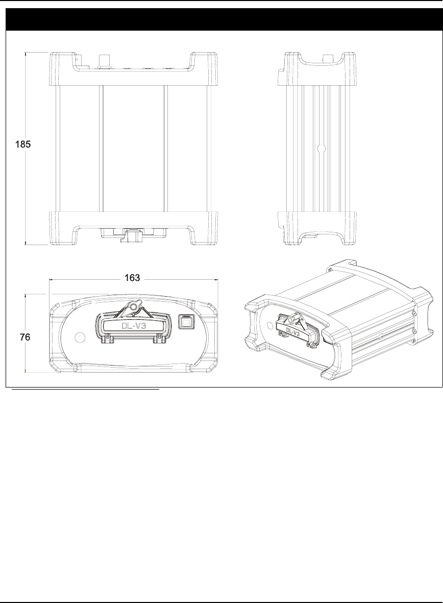
PHYSICAL
Size 185 x 163 x 76 mm
Weight 1.3 kg maximum (including OEMV-3 card)
ENVIRONMENTAL
Operating Temperature -40°C to +75°C
Storage Temperature -45°C to +95°C
Humidity Not to exceed 95% non-condensing
Technical Specifications Appendix A
OEMV Family Installation and Operation User Manual Rev 5B 157
DIMENSIONS
a b
a. All dimension are in millimeters, please use the Unit Conversion section of the GPS+
Reference Manual for conversion to imperial measurements.
b. See also the ProPak-V3 Dimensions section, on Page 164, for the dimensions of the mounting
bracket. The mounting bracket also has a set of instructions with it.

158 OEMV Family Installation and Operation User Manual Rev 5B
Appendix A Technical Specifications
A.6.1 Port Pin-Outs
Table 33: DL-V3 Serial Port Pin-Out Descriptions
Table 34: DL-V3 I/O Port Pin-Out Descriptions
For strobe signal descriptions, please see Section 3.3.1, Strobes on Page 44.
Connector
Pin No. COM1
RS-232 COM2
RS-232 AUX
RS-232
1N/CN/CN/C
2 COM1_Rx COM2_Rx COM3_Rx
3 COM1_Tx COM2_Tx COM3_Tx
4 N/C POUT POUT
5 GND GND GND
6 D (+) N/C N/C
7 RTS1 RTS2 RTS3
8 CTS1 CTS2 CTS3
9 D (-) N/C N/C
Connector Pin No. Signal Name Signal Descriptions
1 VARF Variable frequency out
2 PPS Pulse per second
3 MSR Mark 1 output
4 EVENT1 Mark 1 input
5 PV Valid position available
6 EVENT2 Mark 2 input, which requires a pulse longer than 150 ns. 10K
ohm pull down resistor internal to the DL-V3. Refer
also to the MARKCONTROL command in the OEMV
Firmware Reference Manual.
7 _RESETOUT Reset TTL signal output to an external system. Active low.
8 ERROR Indicates a fatal error when high.
9 GND Digital ground
Technical Specifications Appendix A
OEMV Family Installation and Operation User Manual Rev 5B 159
A.6.2 Cables
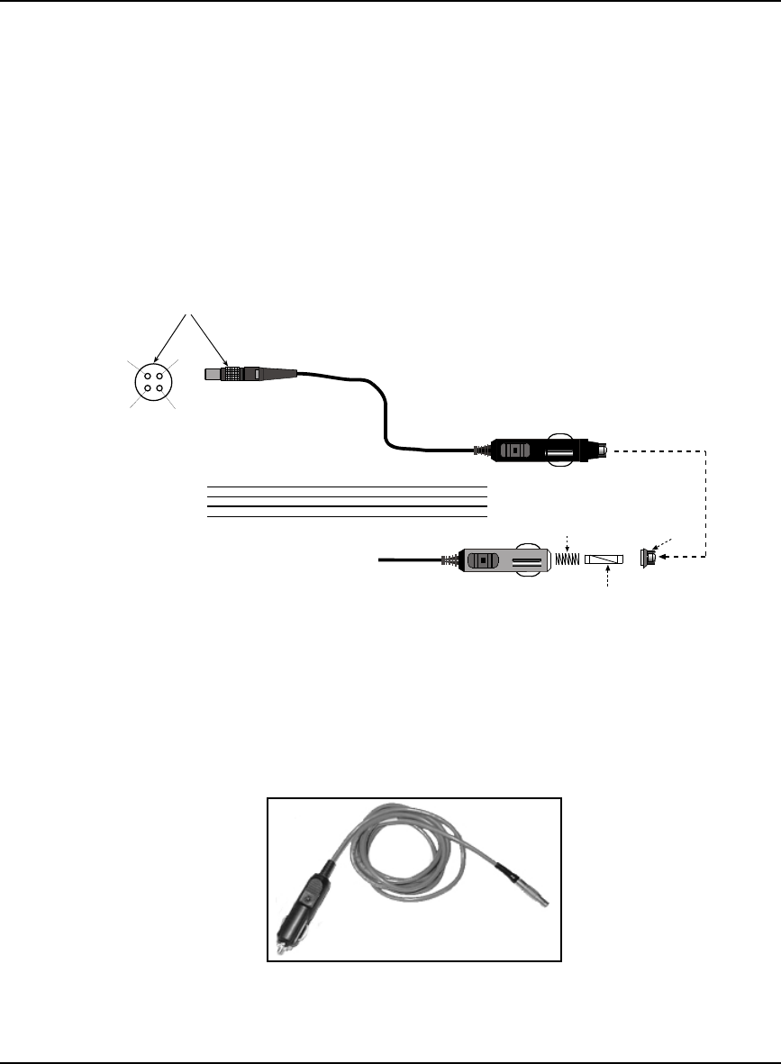
A.6.2.1 12V Power Adapter Cable (NovAtel part number 01017663)
The power adapter cable supplied with the DL-V3, see Figure 60, provides a convenient means for
supplying +12 V DC while operating in the field.
Input is provided through the standard 12V power outlet. The output from the power adapter utilizes a
4-pin LEMO connector (LEMO part number FGG.0B.304.CLAD52Z) and plugs directly into the
PWR input located on the back panel of the DL-V3.
This cable is RoHS compliant.
For alternate power sources please see Section 3.1.3 on Page 34.
Reference Description Reference Description
1 Black 5 Ground
2 Red 6 +6 to +18 V DC
3 Orange 7 +6 to +18 V DC
4 Brown 8 Ground
9 Connector key marking 12 Universal tip
10 12V adapter 13 6 Amp slow-blow fuse
11 Spring
Figure 56: DL-V3 Power Cable
-
+
-
+
1
4
3
2
1 (-) 4 (-)
3 (+)
2 (+)
9
5
6
7
8
10
12
11
13
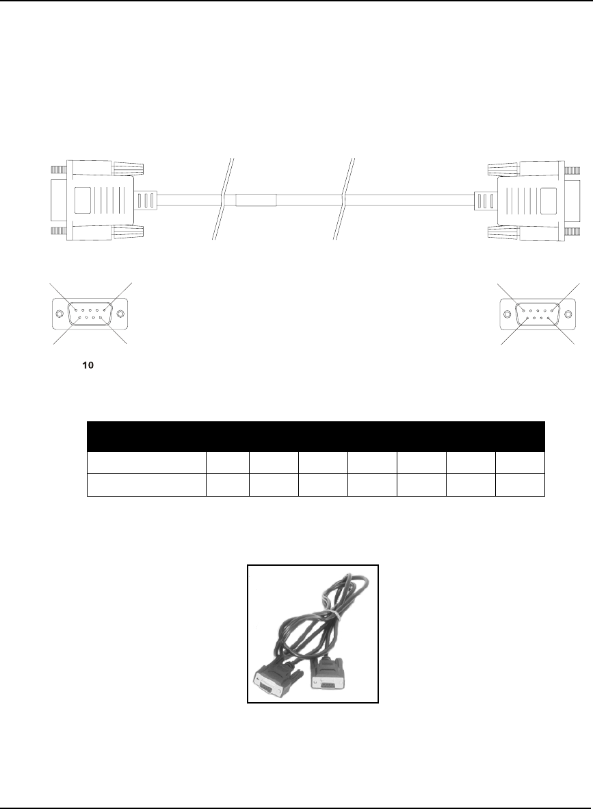
160 OEMV Family Installation and Operation User Manual Rev 5B
Appendix A Technical Specifications
A.6.2.2 Null Modem Cable (NovAtel part number 01017658)
This cable supplied with the DL-V3, see Figure 61, provides an easy means of communications with a
PC. The cable is equipped with a 9-pin connector at the receiver end which can be plugged into the
COM1, COM2, or AUX port. At the PC end, a 9-pin connector is provided to accommodate a PC serial
(RS-232) communication port.
This cable is RoHS compliant.
Wiring Table:
Reference Description
10 DB9S (Female)
11 DB9S (Female)
Figure 57: DL-V3 Null Modem Cable
Connector Pin Number
To DB9S (10)2387451 & 6
To DB9S (11)32781 & 654
5
11
5
6
99
6
11
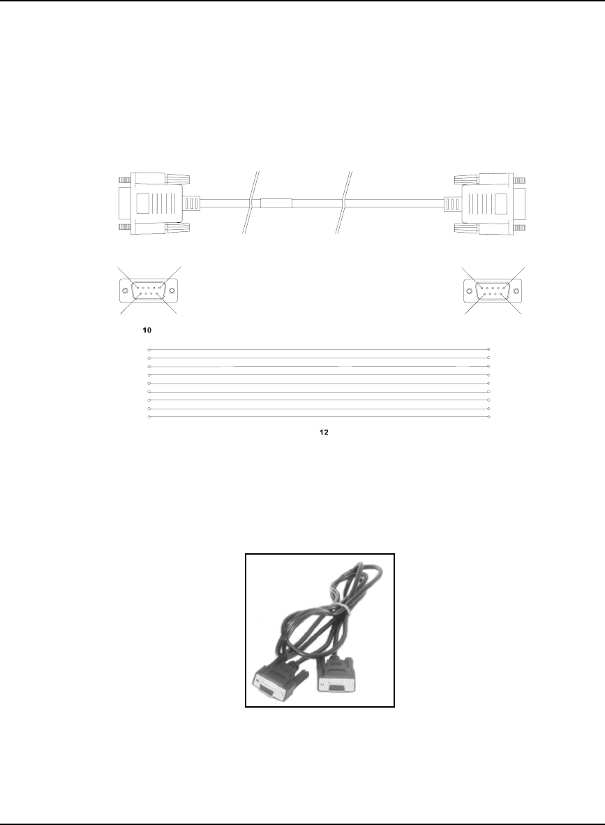
Technical Specifications Appendix A
OEMV Family Installation and Operation User Manual Rev 5B 161
A.6.2.3 Straight Through Serial Cable (NovAtel part number 01017659)
This cable can be used to connect the DL-V3 to a modem or radio transmitter to propagate differential
corrections. The cable is equipped with a female DB9 connector at the receiver end. The male DB9
connector at the other end is provided to plug into your user-supplied equipment (please refer to your
modem or radio transmitter user guide for more information on its connectors). The cable is
approximately 2 m in length. See Figure 62.
This cable is RoHS compliant.
Reference Description Reference Description
10 DB9P (male) connector 12 9-conductor cable
11 DB9S (female) connector
Figure 58: DL-V3 Straight Through Serial Cable
5
11
5
6
99
6
11
1
2
3
4
5
6
1
2
3
4
5
6
7
8
9
9
7
8
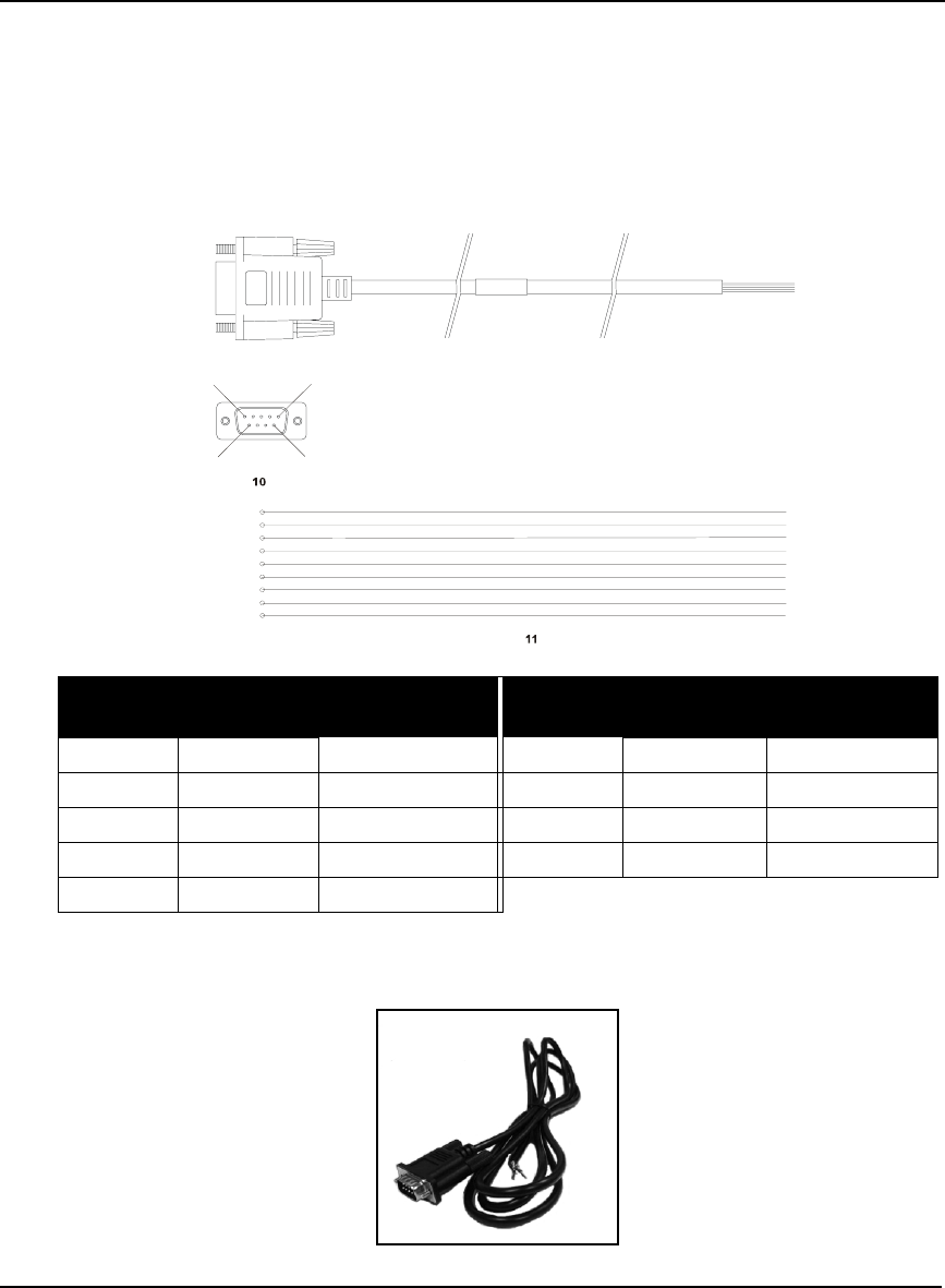
162 OEMV Family Installation and Operation User Manual Rev 5B
Appendix A Technical Specifications
A.6.2.4 I/O Strobe Port Cable (NovAtel part number 01017660)
The strobe lines on the DL-V3 can be accessed by inserting the male DB9 connector of the I/O strobe
port cable into the I/O port. The other end of this cable is provided without a connector to provide
flexibility. The jacket insulation is cut away slightly from the end but the insulation on each wire is
intact. The cable is approximately 2 m in length. See Figure 63.
This cable is RoHS compliant.
Wiring Table:
Reference Description Reference Description
10 DB9P (male) connector 11 9-conductor cable
Figure 59: DL-V3 I/O Strobe Port Cable
I/O Port
Pin I/O Port
Signal I/O Port Cable
Wire Color I/O Port
Pin I/O Port
Signal I/O Port Cable
Wire Color
1 VARF Black 6 Event2 Green
2 PPS Brown 7 _RESETOUT Blue
3 MSR Red 8 ERROR Violet
4 Event1 Orange 9 GND White/Grey
5 PV Yellow
15
9
6
1
2
3
4
5
6
9
7
8

Technical Specifications Appendix A
OEMV Family Installation and Operation User Manual Rev 5B 163
A.7 ProPak-V3
INPUT/OUTPUT CONNECTORS
Antenna Input TNC female jack, 50 Ω nominal impedance
+4.75 to +5.10 V DC, 100 mA max
(output from ProPak-V3 to antenna/LNA)
PWR 4-pin LEMO connector
+6 to +18 V DC at 2.8 W (typical) a b
a. For SPAN applications, this becomes +9 to +18 V DC
b. When tracking GPS satellites
COM1
COM2
AUX
I/O
OSC
DB9P connector
DB9P connector
DB9P connector c
DB9S connector
BNC connector (external oscillator)
c. The AUX port on the ProPak-V3 supports input from an IMU. If applicable, refer also to
your SPAN User Manual. This port, although labelled AUX, is COM3.
PHYSICAL
Size 185 x 160 x 71 mm
Weight 1.0 kg maximum (including OEMV-3 card)
ENVIRONMENTAL
Operating Temperature -40°C to +75°C
Storage Temperature -45°C to +95°C
Humidity Not to exceed 95% non-condensing
Tested to these standards: MIL-STD-810F 512.4 Procedure 1 Waterproof Immersion
IEC 60529 IPX7 Waterproof
MIL-STD-810F 509.4 Salt Spray
MIL-STD-810F 510.4 Sand and Dust
IEC 68-2-27Ea Shock (non-operating)
MIL-STD-202G 214A Vibration (random)
SAE J/211 4.7 Vibration (sinusoidal)
FCC Part 15/ EN55022 Class B Emissions
EN 61000-6-2 Immunity
EN60950 Safety
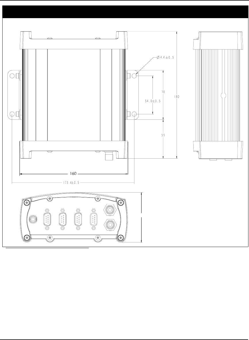
164 OEMV Family Installation and Operation User Manual Rev 5B
Appendix A Technical Specifications
DIMENSIONS
a
a. All dimension are in millimeters, please use the Unit Conversion section of the GPS+
Reference Manual for conversion to imperial measurements.
71

Technical Specifications Appendix A
OEMV Family Installation and Operation User Manual Rev 5B 165
A.7.1 Port Pin-Outs
Table 35: ProPak-V3 Serial Port Pin-Out Descriptions
Table 36: ProPak-V3 I/O Port Pin-Out Descriptions
For strobe signal descriptions, please see Section 3.3.1, Strobes on Page 44.
Connector
Pin No.
COM1 COM2 AUX
RS-232 RS-422 RS-232 Only RS-232 RS-422
1 Reserved Reserved N/C N/C N/C
2 COM1_Rx COM1_Rx (+) COM2_Rx COM3_Rx COM3_Rx (+)
3 COM1_Tx COM1_Tx (+) COM2_Tx COM3_Tx COM3_Tx (+)
4 N/C N/C POUT POUT POUT
5 GND GND GND GND GND
6 D (+) D (+) N/C N/C N/C
7 RTS1 COM1_Tx (-) RTS2 RTS3 COM3_Tx (-)
8 CTS1 COM1_Rx (-) CTS2 CTS3 COM3_Rx (-)
9 D (-) D (-) N/C N/C N/C
Connector Pin No. Signal Name Signal Descriptions
1 VARF Variable frequency out
2 PPS Pulse per second
3 MSR Mark 1 output
4 EVENT1 Mark 1 input
5 PV Valid position available
6 EVENT2 Mark 2 input, which requires a pulse longer than 150 ns. 10K
ohm pull down resistor internal to the ProPak-V3.
Refer also to the MARKCONTROL command in the
OEMV Firmware Reference Manual.
7 _RESETOUT Reset TTL signal output to an external system. Active low.
8 ERROR Indicates a fatal error when high.
9 GND Digital ground
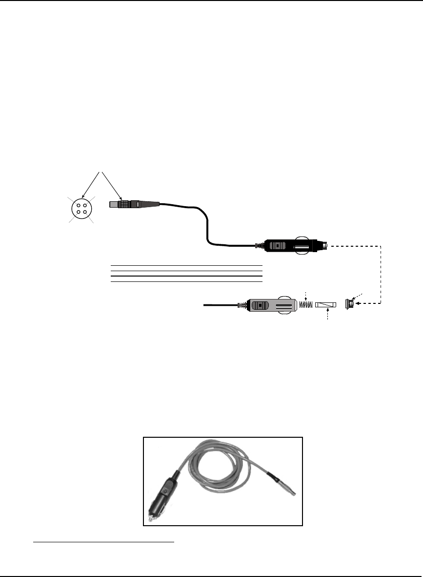
166 OEMV Family Installation and Operation User Manual Rev 5B
Appendix A Technical Specifications
A.7.2 Cables
A.7.2.1 12V Power Adapter Cable (NovAtel part number 01017663)
The power adapter cable supplied with the ProPak-V3, see Figure 60, provides a convenient means
for supplying +12 V DC while operating in the field.
Input is provided through the standard 12V power outlet. The output from the power adapter utilizes a
4-pin LEMO connector (LEMO part number FGG.0B.304.CLAD52Z) and plugs directly into the
PWR input located on the back panel of the ProPak-V3.
This cable is RoHS compliant.
For alternate power sources please see Section 3.1.3 on Page 34.
Reference Description Reference Description
1 Black 5 Ground
2 Red 6 +6 to +18 V DC 1
3 Orange 7 +6 to +18 V DC 1
4 Brown 8 Ground
9 Connector key marking 12 Universal tip
10 12V adapter 13 6 Amp slow-blow fuse
11 Spring
Figure 60: ProPak-V3 Power Cable
1. For SPAN applications this becomes +9 to +18 V DC
-
+
-
+
1
4
3
2
1 (-) 4 (-)
3 (+)
2 (+)
9
5
6
7
8
10
12
11
13
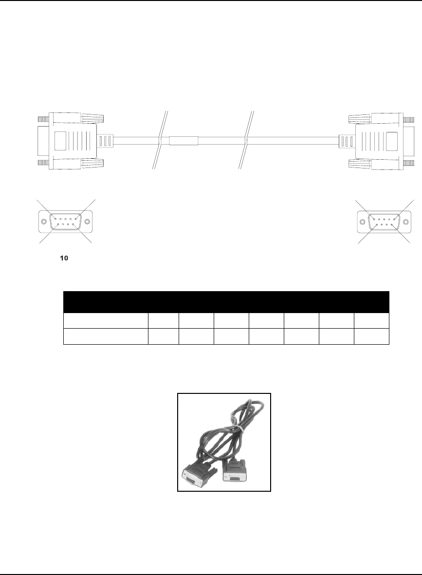
Technical Specifications Appendix A
OEMV Family Installation and Operation User Manual Rev 5B 167
A.7.2.2 Null Modem Cable (NovAtel part number 01017658)
This cable supplied with the ProPak-V3, see Figure 61, provides an easy means of communications
with a PC. The cable is equipped with a 9-pin connector at the receiver end which can be plugged into
the COM1, COM2, or AUX port. At the PC end, a 9-pin connector is provided to accommodate a PC
serial (RS-232) communication port.
This cable is RoHS compliant.
Wiring Table:
Reference Description
10 DB9S (Female)
11 DB9S (Female)
Figure 61: ProPak-V3 Null Modem Cable
Connector Pin Number
To DB9S (10)2387451 & 6
To DB9S (11)32781 & 654
5
11
5
6
99
6
11
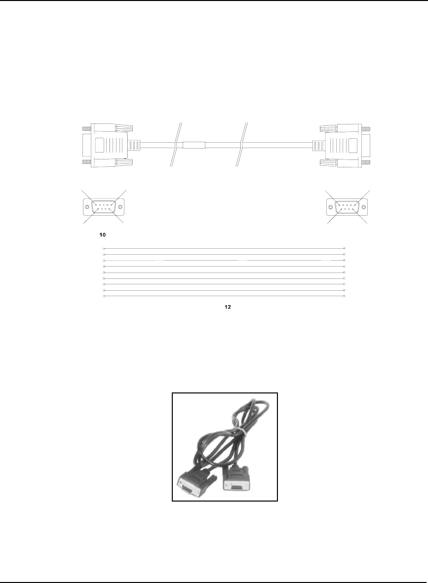
168 OEMV Family Installation and Operation User Manual Rev 5B
Appendix A Technical Specifications
A.7.2.3 Straight Through Serial Cable (NovAtel part number 01017659)
This cable can be used to connect the ProPak-V3 to a modem or radio transmitter to propagate
differential corrections. The cable is equipped with a female DB9 connector at the receiver end. The
male DB9 connector at the other end is provided to plug into your user-supplied equipment (please
refer to your modem or radio transmitter user guide for more information on its connectors). The cable
is approximately 2 m in length. See Figure 62.
This cable is RoHS compliant.
Reference Description Reference Description
10 DB9P (male) connector 12 9-conductor cable
11 DB9S (female) connector
Figure 62: ProPak-V3 Straight Through Serial Cable
5
11
5
6
99
6
11
1
2
3
4
5
6
1
2
3
4
5
6
7
8
9
9
7
8

Technical Specifications Appendix A
OEMV Family Installation and Operation User Manual Rev 5B 169
A.7.2.4 I/O Strobe Port Cable (NovAtel part number 01017660)
The strobe lines on the ProPak-V3 can be accessed by inserting the male DB9 connector of the I/O
strobe port cable into the I/O port. The other end of this cable is provided without a connector to
provide flexibility. The jacket insulation is cut away slightly from the end but the insulation on each
wire is intact. The cable is approximately 2 m in length. See Figure 63.
This cable is RoHS compliant.
Wiring Table:
Reference Description Reference Description
10 DB9P (male) connector 11 9-conductor cable
Figure 63: ProPak-V3 I/O Strobe Port Cable
I/O Port
Pin I/O Port
Signal I/O Port Cable
Wire Color I/O Port
Pin I/O Port
Signal I/O Port Cable
Wire Color
1 VARF Black 6 Event2 Green
2 PPS Brown 7 _RESETOUT Blue
3 MSR Red 8 ERROR Violet
4 Event1 Orange 9 GND White/Grey
5 PV Yellow
15
9
6
1
2
3
4
5
6
9
7
8
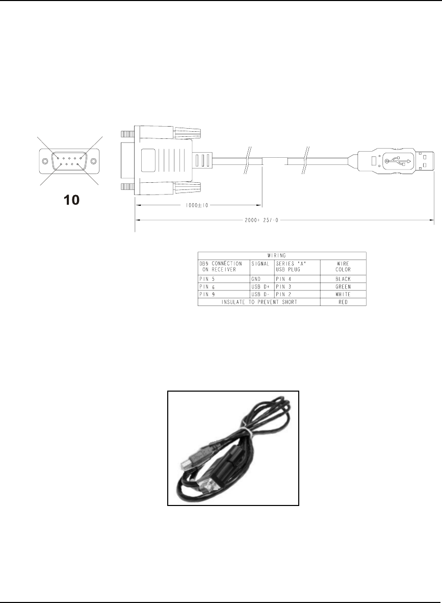
170 OEMV Family Installation and Operation User Manual Rev 5B
Appendix A Technical Specifications
A.7.2.5 USB Serial Cable (NovAtel part number 01017664)
The USB cable shown below provides a means of interfacing between the COM1 port on the ProPak-
V3 and another serial communications device, such as a PC. At the ProPak-V3 end, the cable is
equipped with a DB9 connector, which plugs directly into a COM port. At the other end, a USB
connector is provided.
This cable is RoHS compliant.
Reference Description
10 Female DB9 connector
11 USB connector
Figure 64: USB Serial Cable
1
5
96
8
11

Technical Specifications Appendix A
OEMV Family Installation and Operation User Manual Rev 5B 171
A.8 FlexPak-V1, FlexPak-V1G and FlexPak-V2
INPUT/OUTPUT CONNECTORS
ANT Waterproof TNC female jack, 50 Ω nominal impedance
+4.75 to +5.10 V DC, 100 mA max (output from FlexPak to antenna/LNA)
PWR 3-pin waterproof Deutsch connector
+6 to +18 V DC
(Deutsch PN 59065-09-98PN)
COM1 13-pin waterproof Deutsch connector
(Deutsch P/N 59065-11-35PF)
COM2 13-pin waterproof Deutsch connector a
(Deutsch P/N 59065-11-35PF)
a. Normally RS-232 but can be dynamically changed to RS-422 by grounding Pin# 1 on the
COM2 Deutsch connector. You can switch between RS-232 and RS-422 by changing the state
of this pin. You do not have to cycle power on the FlexPak for this change to take effect.
Pin# 1 is a No Connect (N/C) at the DB9F end of the FlexPak communication cable, see Page
177. There are not enough pins on the DB9F connector to accommodate this extra pin. How-
ever, if you cut the COM cable you can access wires for all the pins on the Deutsch side of the
cable, including the Deutsch Pin# 1.
PHYSICAL
Size 45 x 147 x 123 mm
Weight 350 g maximum
Mounting System Integral flange with two 7 mm (9/32 inch) diameter mounting holes 133
mm (5.25 inches) apart
ENVIRONMENTAL
Operating Temperature -40°C to +85°C
Storage Temperature -40°C to +85°C
Humidity Not to exceed 95% non-condensing
Waterproof To IEC 60529 IP X7
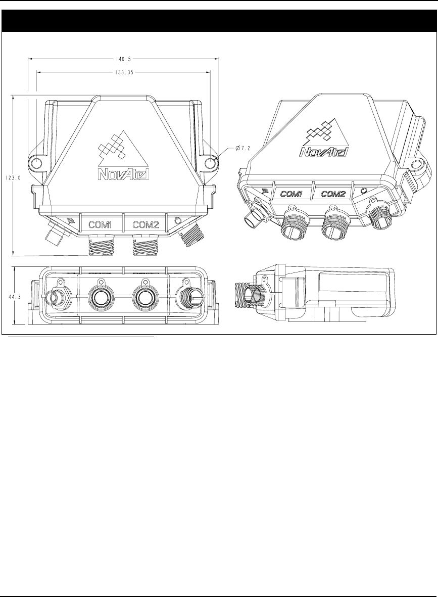
172 OEMV Family Installation and Operation User Manual Rev 5B
Appendix A Technical Specifications
DIMENSIONS
a
a. All dimension are in millimeters, please use the Unit Conversion section of the GPS+ Reference
Manual for conversion to imperial measurements.

Technical Specifications Appendix A
OEMV Family Installation and Operation User Manual Rev 5B 173
A.8.1 Port Pin-Outs
The pin numbering for each of the ports, is described in the tables that follow.
Table 37: FlexPak COM1 Port Pin-Out Descriptions
For strobe signal descriptions, please see . See also Section 3.3.1, Strobes on Page 44.
Deutsch RS-232 Only
Connector Pin No. Signal Name
1GPIO
2 COM1_Rx
3CTS1
4 EVENT1
5GND
6 EVENT2
7RTS1
8 COM1_Tx
9POUT a
a. The current is limited to 1.5 A
10 PPS
11 USB D (+)
12 USB D (-)
13 ERROR

174 OEMV Family Installation and Operation User Manual Rev 5B
Appendix A Technical Specifications
Table 38: FlexPak COM2 Port Pin-Out Descriptions
The cable supplied needs to be modified to work in RS-422 mode, see Section A.8.2.2, 13-Pin
Deutsch to DB9 Null Modem Cable (NovAtel part number 01017822) on Page 176.
Deutsch RS-232 Deutsch RS-422
Pin Function Pin Function
1 Select 232/
422
Mode
1 Select 232/
422
Mode
2 COM2_Rx 2 COM2_Rx (+)
3CTS3COM2_Rx (-)
4 Event 1 4 Event 1
5GND5GND
6 Event 2 6 Event 2
7 RTS2 7 COM2_Tx (+)
8 COM2_Tx 8 COM2_Tx (-)
9POUT a
a. The current is limited to 1.5 A
9POUT a
10 PPS 10 PPS
11 USB D (+) 11 USB D (+)
12 USB D (-) 12 USB D (-)
13 ERROR 13 ERROR
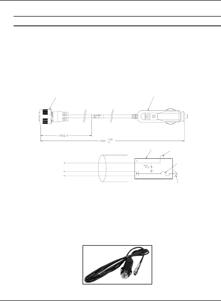
Technical Specifications Appendix A
OEMV Family Installation and Operation User Manual Rev 5B 175
A.8.2 Cables
Deutsch cable connector pin numbers are labelled on the connectors.
A.8.2.1 12V Power Adapter Cable (NovAtel part number 01017821)
The power adapter cable supplied with the FlexPak provides a convenient means for supplying +12 V
DC while operating from a 12V source (the actual voltage range for the receiver is +6 to +18 V DC).
The figure below shows the cable and a wiring diagram of the 12V adapter.
The output of the power adapter uses a 3-pin Deutsch socket (Deutsch part number: 59064-09-98SN).
This cable plugs directly into the PWR port on the front of the FlexPak.
Reference Description Reference Description
1 3-pin Deutsch connector A Black
2 12V adapter B Red
3 Outer contact C White/Natural
4 3 amp slow-blow fuse
5 Center contact
6 Foil shield
Figure 65: FlexPak Power Cable
12
23
4
5
6
A
B
C
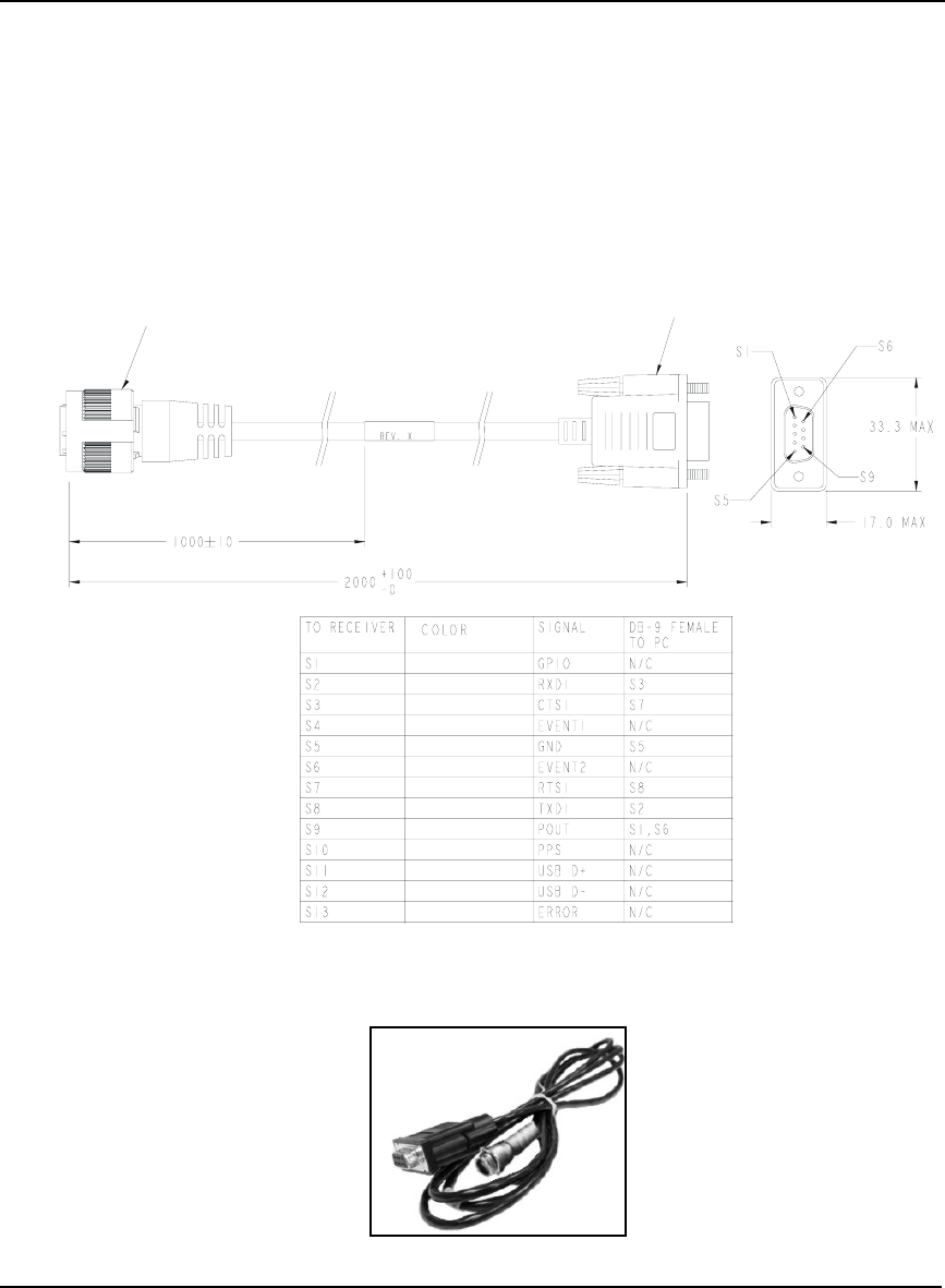
176 OEMV Family Installation and Operation User Manual Rev 5B
Appendix A Technical Specifications
A.8.2.2 13-Pin Deutsch to DB9 Null Modem Cable (NovAtel part number 01017822)
The null modem serial cable shown below provides a means of interfacing between the COM1 or
COM2 port on the FlexPak and another serial communications device, such as a PC. At the FlexPak
end, the cable is equipped with a 13-pin Deutsch connector (Deutsch part number: 59064-11-35SF),
which plugs directly into a COM port. At the other end, a RS-232 DB9S connector is provided. To use
this cable in RS-422 mode, you must cut the DB-9 connector off and make a cable to match the
COM2 port for RS-422, see Section 38, FlexPak COM2 Port Pin-Out Descriptions on Page 174. This
cable looks identical to the straight through serial cable, see Page 177, but its use and part number
differs. It is 2 meters in length.
Reference Description
1 13-pin Deutsch connector
2 DB9S connector
Figure 66: FlexPak 13-Pin Serial Cable
12
BROWN
BROWN/WHITE
GREEN
BLUE
GREEN/BLACK
RED
RED/BLACK
YELLOW/BLACK
ORANGE
WHITE
WHITE/BLACK
ORANGE/BLACK
BLUE/WHITE
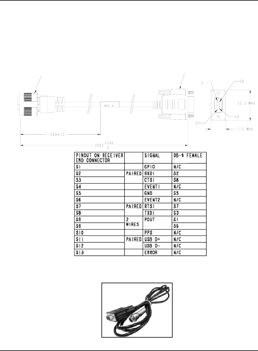
Technical Specifications Appendix A
OEMV Family Installation and Operation User Manual Rev 5B 177
A.8.2.3 13-Pin Deutsch to DB9 Straight Cable (NovAtel part number 01017823)
The straight through serial cable shown below is used to connect the FlexPak to a modem or radio
transmitter to propagate differential corrections. At the FlexPak end, the cable is equipped with a 13-
pin Deutsch connector (Deutsch part number: 59064-11-35SF), which plugs directly into a COM port.
The female DB9 connector at the other end is provided to plug into your user-supplied equipment
(please refer to your modem or radio transmitter user guide for more information on its connectors).
This cable looks identical to the null modem serial cable, see Page 176, but its use and part number
differs. It is 2 meters in length.
Reference Description
1 13-pin Deutsch connector
2 DB9S connector
Figure 67: FlexPak 13-Pin Serial Cable
12
BROWN
BROWN/WHITE
GREEN
BLUE
GREEN/BLACK
RED
RED/BLACK
YELLOW/BLACK
ORANGE
WHITE
WHITE/BLACK
ORANGE/BLACK
BLUE/WHITE
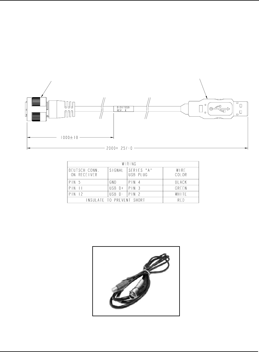
178 OEMV Family Installation and Operation User Manual Rev 5B
Appendix A Technical Specifications
A.8.2.4 USB Serial Cable (NovAtel part number 01017820)
The USB cable shown below provides a means of interfacing between the COM1 or COM2 port on
the FlexPak and another serial communications device, such as a PC. At the FlexPak end, the cable is
equipped with a 13-pin Deutsch connector (Deutsch part number: 59064-11-35SF), which plugs
directly into the COM2 port. See also Section A.8.2.3, 13-Pin Deutsch to DB9 Straight Cable (NovAtel
part number 01017823) on Page 177. At the other end, a USB connector is provided.
Reference Description
1 Deutsch connector
2 USB connector
Figure 68: FlexPak USB Cable
1
2

Technical Specifications Appendix A
OEMV Family Installation and Operation User Manual Rev 5B 179
A.9 SMART-V1
INPUT/OUTPUT CONNECTORS
WARNING!: It is important that you read the SMART-V1 Power Warning on Page 11 of the
Notice section.
USB model port 18-pin Switchcraft RS-232
+9 to +28 V DC 2.5 W (typical) power consumption
CAN model port 18-pin Switchcraft RS-232
+9 to +28 V DC 2.5 W (typical) power consumption
PHYSICAL
Size 114.3 mm Diameter x 95.6 mm Height
(4.5" Diameter x 3.76" Height)
Weight 525 g maximum excluding cable (1.16 lb.)
Mounting System 1-14 UNS threads x 1” deep and/or
3 x 10-32 UNF screws
ENVIRONMENTAL
Operating Temperature -40°C to +75°C (-40°F to +167°F)
Storage Temperature -55°C to +90°C (-67°F to +194°F)
Humidity Not to exceed 95% non-condensing
Tested to all these
standards Waterproof/Immersion MIL-STD-810F 512.4 Procedure I
Salt Spray MIL-STD-810F 509.4
Sand and Dust MIL-STD-810F 510.4
UV Light Protection ASTM G-151
Shock MIL-STD-810F 516.5
Vibration (Random) MIL-STD-801F 514.5 C17
Vibration (Sine) SAE EP455
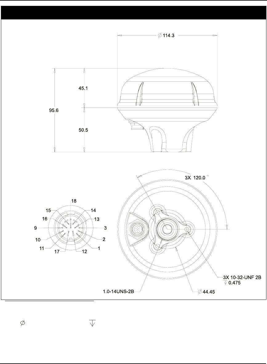
180 OEMV Family Installation and Operation User Manual Rev 5B
Appendix A Technical Specifications
DIMENSIONS
a b
a. All dimension are in millimeters, please use the Unit Conversion section of the GPS+ Reference
Manual for conversion to imperial measurements.
b. indicates a diameter and indicates a depth.

Technical Specifications Appendix A
OEMV Family Installation and Operation User Manual Rev 5B 181
A.9.1 Port Pin-Outs
The pin numbering for the SMART-V1 port, USB followed by CAN models, is described in the tables
that follow.
Table 39: SMART-V1 USB Model Port Pin-Out Descriptions
For strobe signal descriptions, please see . See also Section 3.3.1, Strobes on Page 44.
Switchcraft RS-232
Pin Function
1PWR
2GND
3TX2
4RX2
5TX1 (+)
6RX1 (+)
7 TX1 (-)
8 RX1 (-)
9 Reserved
10 USB D (-)
11 Digital GND
12 TIMEMARK
13 TX3 (+)
14 RX3 (+)
15 TX3 (-)
16 USB D (+)
17 PWR2
18 GND2

182 OEMV Family Installation and Operation User Manual Rev 5B
Appendix A Technical Specifications
Table 40: SMART-V1 CAN Model Port Pin-Out Descriptions
Switchcraft RS-232
Pin Function
1PWR
2GND
3CAN H
4CAN L
5TX1 (+)
6RX1 (+)
7TX1 (-)
8 RX1 (-)
9 CAN PWR
10 CAN GND
11 Digital GND
12 TIMEMARK
13 TX3 (+)
14 RX3 (+)
15 TX3 (-)
16 RX3 (-)
17 PWR2
18 GND2
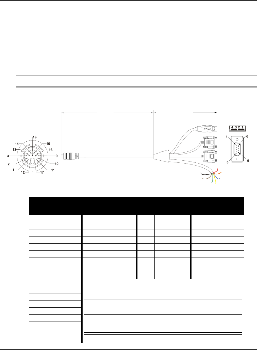
Technical Specifications Appendix A
OEMV Family Installation and Operation User Manual Rev 5B 183
A.9.2 Optional Cables
Each SMART-V1 comes with its own multi-cable in either a USB (NovAtel part number 01017893)
or CAN format (NovAtel part number 01017894). These cables are also available with no connectors
at the USB or CAN end (NovAtel part numbers 01017923 and 01017922 respectively) but with tin-
terminated ends. All 4 cables have an 18-pin Switchcraft connector at one end and are 3 m in length.
Section A.9.2.1 below contains pin-out information for a SMART-V1 USB multi-cable while Section
A.9.2.2 on Page 184 contains pin-out information for a SMART-V1 CAN multi-cable. Figures 69 and
70 on Page 185 show examples of the cables with their DB-9 and/or USB ends.
Switchcraft cable connector pin numbers are labelled on the connectors.
A.9.2.1 18-Pin Switchcraft to USB Multi-Cable (NovAtel part number 01017893)
Table 41: USB Multi-Cable Connector Pin-Outs
2.5 m
0.5 m
J3
J2
J4
PWR
PWR2
TIMEMARK
Reser
v
ed
DIG GND
GND2
GND
J1 Switchcraft J2 DB-9 socket J3 DB-9 socket J4 USB A
Pin Signal Pin Signal Pin Signal Pin Signal
1 PWR 1 N/A 1 N/A 1 N/A
2 GND 2 TX1 (+) 2 TX2 2 USB D (-)
3 TX2 3 RX1 (+) 3 RX2 3 USB D (+)
4 RX2 4 N/A 4 N/A 4 Digital GND
5 TX1 (+) 5 Digital GND 5 Digital GND
6 RX1 (+) 6 N/A 6 N/A
7 TX1 (-) 7 N/A 7 N/A
8 RX1 (-) 8 N/A 8 N/A
9 Reserved 9 N/A 9 N/A
10 USB D (-) See also Table 43 on Page 184 for the optional USB cable’s
bare tagged wire colors.
WARNING!: It is important that you read the SMART-V1
Power Warning on Page 11 of the Notice section.
11 Digital GND
12 TIMEMARK
13 TX3 (+)
14 RX3 (+)
15 TX3 (-)
16 USB D (+)
17 PWR2
18 GND2
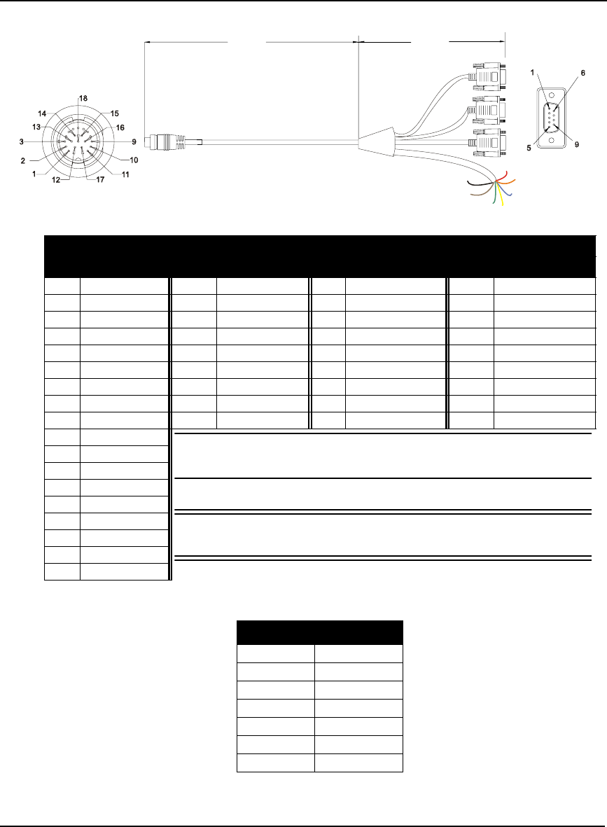
184 OEMV Family Installation and Operation User Manual Rev 5B
Appendix A Technical Specifications
A.9.2.2 18-Pin Switchcraft to CAN Multi-Cable (NovAtel part number 01017894)
Table 42: CAN Multi-Cable Connector Pin-Outs
Table 43: USB or CAN Multi-Cables Bare Tagged Wire Colors
2.5 m
0.5 m
J3
J2
J4
PWR
PWR2
TIMEMARK
Reserved
DIG GND
GND2
GND
J1 Switchcraft J2 DB-9 plug J3 DB-9 socket J4 DB-9 socket
Pin Signal Pin Signal Pin Signal Pin Signal
1PWR 1 N/A 1N/A 1 N/A
2 GND 2 TX1 (+) 2 CANH 2 TX3 (+)
3 CANH 3 RX1 (+) 3 CANL 3 RX3 (+)
4 CANL 4 N/A 4 N/A 4 N/A
5 TX1 (+) 5 Digital GND 5 N/A 5 Digital GND
6 RX1 (+) 6 N/A 6 N/A 6 N/A
7 TX1 (-) 7 TX1 (-) 7 N/A 7 TX3 (-)
8 RX1 (-) 8 RX1 (-) 8 N/A 8 RX3 (-)
9 CAN PWR 9 N/A 9 N/A 9 N/A
10 CAN GND See also Table 43 below for the optional CAN cable’s bare tagged
wire colors.
WARNING!: It is important that you read the SMART-V1 Power
Warning on Page 11 of the Notice section.
11 Digital GND
12 TIMEMARK
13 TX3 (+)
14 RX3 (+)
15 TX3 (-)
16 RX3 (-)
17 PWR2
18 GND2
Color Function
Red PWR
Orange PWR2
Blue TIMEMARK
Yellow Reserved
Green Digital GND
Brown GND2
Black GND
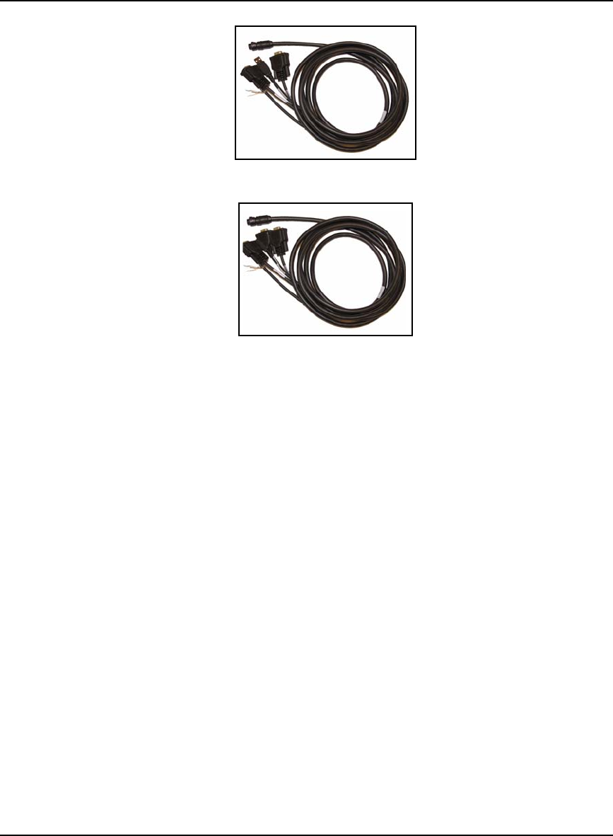
Technical Specifications Appendix A
OEMV Family Installation and Operation User Manual Rev 5B 185
Figure 69: SMART-V1 Optional USB Multi-Cable
Figure 70: SMART-V1 Optional CAN Multi-Cable

186 OEMV Family Installation and Operation User Manual Rev 5B
Appendix B Electrostatic Discharge Control
(ESD) Practices
B.1 Overview
Static electricity is electrical charge stored in an electromagnetic field or on an insulating body. This
charge can flow as soon as a low-impedance path to ground is established. Static-sensitive units can be
permanently damaged by static discharge potentials of as little as 40 volts. Charges carried by the
human body, which can be thousands of times higher than this 40 V threshold, can accumulate
through as simple a mechanism as walking across non-conducting floor coverings such as carpet or
tile. These charges may be stored on clothing, especially when the ambient air is dry, through friction
between the body and/or various clothing layers. Synthetic materials accumulate higher charges than
natural fibers. Electrostatic voltage levels on insulators may be very high, in the order of thousands of
volts.
Various electrical and electronic components are vulnerable to electrostatic discharge (ESD). These
include discrete components, hybrid devices, integrated circuits (ICs), and printed circuit boards
(PCBs) assembled with these devices.
B.2 Handling ESD-Sensitive Devices
ESD-sensitive devices must only be handled in static-controlled locations. Some recommendations
for such handling practices follow:
• Handling areas must be equipped with a grounded table, floor mats, and wrist strap.
• A relative humidity level must be maintained between 20% and 80% non-condensing.
• No ESD-sensitive board or component should be removed from its protective package,
except in a static-controlled location.
• A static-controlled environment and correct static-control procedures are required at both
repair stations and maintenance areas.
• ESD-sensitive devices must be handled only after personnel have grounded themselves
via wrist straps and mats.
• Boards or components should never come in contact with clothing, because normal
grounding cannot dissipate static charges on fabrics.
• A circuit board must be placed into a static shielding bag or clamshell before being
removed from the work location and must remain in the clamshell until it arrives at a
static-controlled repair/test center.
• Circuit boards must not be changed or moved needlessly. Handles may be provided on
circuit boards for use in their removal and replacement; care should be taken to avoid
contact with the connectors and components.
• On-site repair of ESD-sensitive equipment should not be undertaken except to restore
service in an emergency where spare boards are not available. Under these circumstances
repair station techniques must be observed. Under normal circumstances a faulty or
suspect circuit board must be sent to a repair center having complete facilities, or to the
manufacturer for exchange or repair.

Electrostatic Discharge Control (ESD) Practices Appendix B
OEMV Family Installation and Operation User Manual Rev 5B 187
• Where protective measures have not been installed, a suitable alternative would be the use
of a Portable Field Service Grounding Kit (for example, 3M Kit #8501 or #8507). This
consists of a portable mat and wrist strap which must be attached to a suitable ground.
• A circuit board in a static-shielding bag or clamshell may be shipped or stored in a
cardboard carton, but the carton must not enter a static-controlled area such as a grounded
or dissipative bench top or repair zone. Do not place anything else inside the bag (for
example, repair tags).
• Treat all PCBs and components as ESD sensitive. Assume that you will damage the PCB
or component if you are not ESD conscious.
• Do not use torn or punctured static-shielding bags. A wire tag protruding through the bag
could act as a "lightning rod", funneling the entire charge into the components inside the
bag.
• Do not allow chargeable plastics, such as binders, within 0.6 m of unshielded PCBs.
• Do not allow a PCB to come within 0.3 m of a computer monitor.
B.3 Prime Static Accumulators
Table 44 provides some background information on static-accumulating materials.
Table 44: Static-Accumulating Materials
Work Surfaces • formica (waxed or highly resistive)
• finished wood
• synthetic mats
• writing materials, note pads, and so on
Floors • wax-finished
•vinyl
Clothes • common cleanroom smocks
• personal garments (all textiles)
• non-conductive shoes
Chairs • finished wood
•vinyl
• fiberglass
Packing and
handling
• common polyethylene bags, wraps, envelopes, and bubble pack
• pack foam
• common plastic trays and tote boxes
Assembly,
cleaning, and
repair areas
• spray cleaners
• common solder sucker
• common soldering irons
• common solvent brushes (synthetic bristles)
• cleaning, drying and temperature chambers

188 OEMV Family Installation and Operation User Manual Rev 5B
Appendix B Electrostatic Discharge Control (ESD) Practices
B.4 Handling Printed Circuit Boards
ESD damage to unprotected sensitive devices may occur at any time. ESD events can occur far below
the threshold of human sensitivity. Follow this sequence when it becomes necessary to install or
remove a circuit board:
1. After you are connected to the grounded wrist strap, remove the circuit board from the frame and
place it on a static-controlled surface (grounded floor or table mat).
2. Remove the replacement circuit board from the static-shielding bag or clamshell and insert it into
the equipment.
3. Place the original board into the shielding bag or clamshell and seal it with a label.
4. Do not put repair tags inside the shielding bag or clamshell.
5. Disconnect the wrist strap.

OEMV Family Installation and Operation User Manual Rev 5B 189
Appendix C Ethernet Configuration
At power-up, the DL-V3 configures the COM3 multiplexer to switch to the Bluetooth device by
default. In order to use the Ethernet device, the multiplexer must be switched to use Ethernet. To do
this, follow one of the two methods outlined in this appendix.
C.1 Physical Set-Up
Below are the configuration methods described in this appendix and the hardware you require to set
them up:
• Configuration Via Network Cable
- DL-V3 with power cable and serial communications cable
- User-supplied laptop with an available Ethernet port, serial port (or USB port with
NovAtel serial to USB drivers) and the Lantronix software, described below, installed
- CAT5 Ethernet cross-over cable (or use a switch with a straight through Ethernet cable)
• Configuration Via Serial and Network Parameters
- DL-V3 with power cable
- User-supplied laptop with the Lantronix software, described below, installed
- Serial null-modem cable to connect from the laptop and switch between COM1 and
COM2 on the DL-V3. You can avoid switching if you have two serial connections on
your laptop and two null-modem cables. Also, if your laptop has only USB connectors,
you need a USB to serial adaptor between the null-modem cable and the laptop’s USB
connector.
- CAT5 Ethernet cross-over cable (or use a switch with a straight through Ethernet cable)
In both cases, first install the DeviceInstaller and Com Port Redirector utilities programs onto the
laptop you intend to use with your DL-V3 from the Lantronix website at: http://www.lantronix.com/
device-networking/utilities-tools/.
Figure 71, CAT5 Ethernet Cable Connection on Page 190 shows the two methods of physically
providing an Ethernet connection between your laptop and DL-V3. The top shows a direct connection
using a CAT5 Ethernet cross-over cable and the bottom shows two straight-through CAT5 Ethernet
cables with a DSS-5+ port switch in between them.
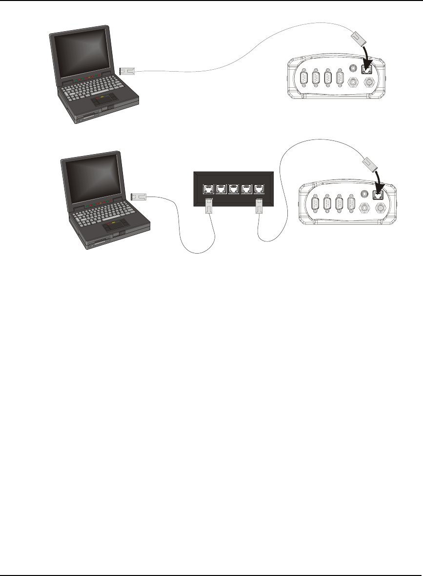
190 OEMV Family Installation and Operation User Manual Rev 5B
Appendix C Ethernet Configuration
Figure 71: CAT5 Ethernet Cable Connection
Reference Description
1 User-supplied laptop computer with Ethernet connector
2 DL-V3 (powered)
3 User-supplied CAT5 Ethernet cross-over cable
4 User-supplied DSS-5+ Port Switch
5 User-supplied CAT5 Ethernet straight-through cables
C.2 Configuration Overview
Both configuration methods are used to provide the DL-V3 with a static Internet Protocol (IP) address
to be used in your personal network. To do this, your Network Administrator must assign a static IP
address to you so that every time there is a receiver start-up, it has the same IP address. Otherwise, the
Ethernet module in the DL-V3 is DHCP-enabled by default where DHCP is an acronym for Dynamic
Host Configuration Protocol. This means that normally the Ethernet device issues a new IP address
every time the receiver is started up. A static IP aids with remote work especially.
C.3 Configuration Via Network Cable
To physically connect the DL-V3 to Ethernet, follow these steps:
1. Connect a CAT5 cross-over cable to a laptop with a free Ethernet port
2. Connect the other end of the CAT5 crossover cable to the DL-V3’s Ethernet port
1
2
1
2
3
4
5
5
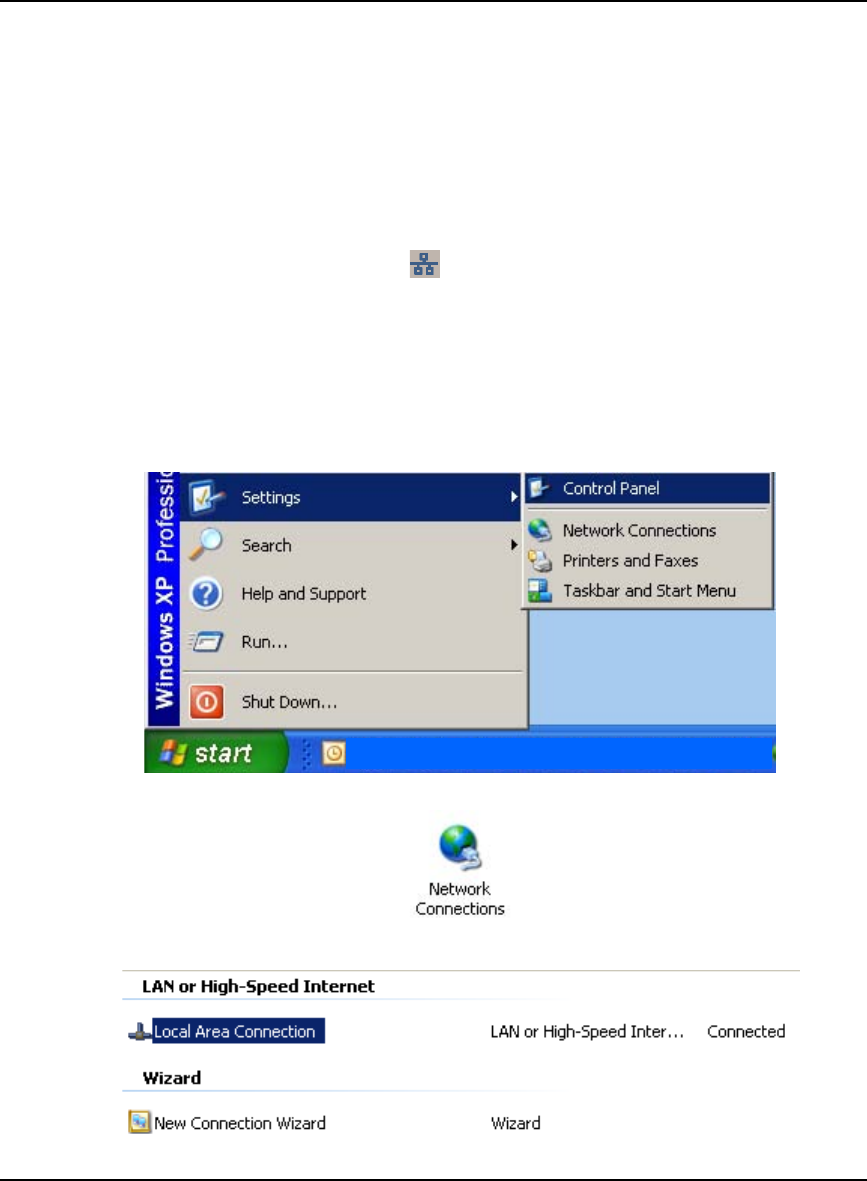
Ethernet Configuration Appendix C
OEMV Family Installation and Operation User Manual Rev 5B 191
3. Connect the power cable to the DL-V3 and power-up the unit
C.3.1 Enable Ethernet on DL-V3 Receiver
From the laptop, connect the DL-V3 to a serial, or USB, cable. Open communication with the receiver
using HyperTerminal or CDU. Issue the following command:
APPCONTROL BLUETOOTH 1
Restart your laptop. COM3 switches from the Bluetooth to the Ethernet device in the DL-V3. You can
see this because the Ethernet LED, labelled , on the DL-V3 now glows orange.
C.3.2 Windows XP Network Settings
If using TCP/IP networking on a Windows XP-based PC or laptop, Windows may be configured to
obtain an IP address automatically. However, an alternate IP must be configured manually rather than
having an automatically generated private IP address. To do this, follow these steps:
1. Click on the Start button in Windows and select Settings | Control Panel.
2. Select Network Connections in Control Panel, and double-click on it.
3. Highlight Local Area Connection and double-click on it.
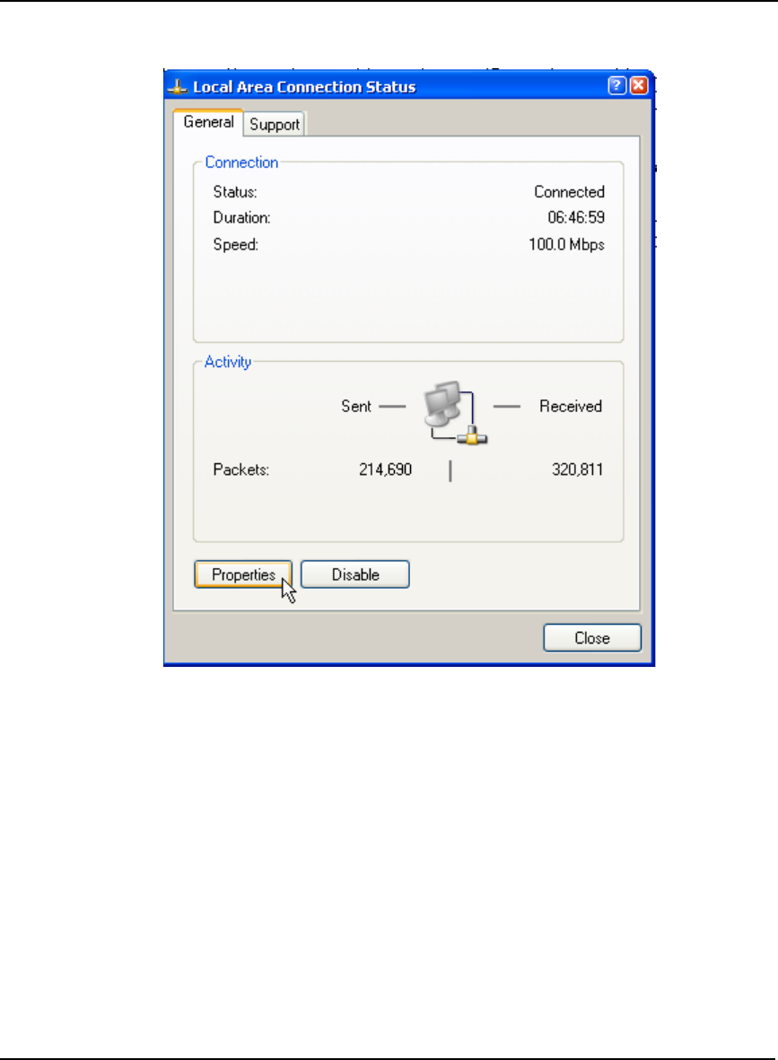
192 OEMV Family Installation and Operation User Manual Rev 5B
Appendix C Ethernet Configuration
4. Click on Properties in the General tab in the Local Area Connection dialog that appears. The
Local Area Connection Properties dialog appears.
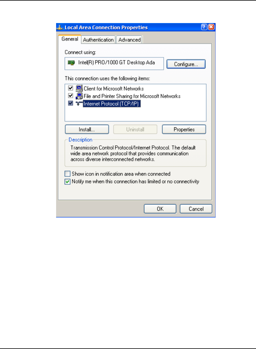
Ethernet Configuration Appendix C
OEMV Family Installation and Operation User Manual Rev 5B 193
5. Select Internet Protocol (TCP/IP) and click on the Properties button. The Internet Protocol TCP/
IP Properties dialog appears.
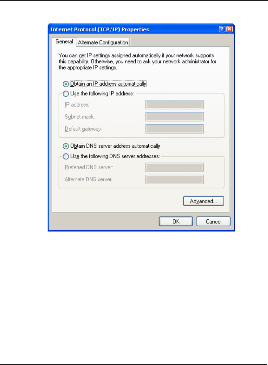
194 OEMV Family Installation and Operation User Manual Rev 5B
Appendix C Ethernet Configuration
6. Ensure the Obtain an IP address automatically and Obtain DNS server address automatically
radio buttons are selected in the General tab.
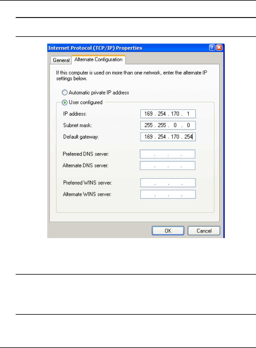
Ethernet Configuration Appendix C
OEMV Family Installation and Operation User Manual Rev 5B 195
7. Select the Alternate Configuration tab in the Internet Protocol (TCP/IP) Properties dialog.
Step 7, above, is very important. If the Alternate Configuration tab is not selected, this
procedure will not work.
8. Ensure that the User Configured radio button is selected. Change the settings to something
similar to the fictional examples shown on this page (check with your Network Administrator for
details) and click OK.
1. The described IP address, and its respective submask and gateway, are for a private Auto
IP, class B, designated IP address and you should obtain yours from your Network
Administrator.
2. Record your IP Address, Network Mask and Gateway numbers for future use.
9. Click OK when you are returned to the Local Area Connection Properties dialog.
10. Click Close to complete the network configuration.
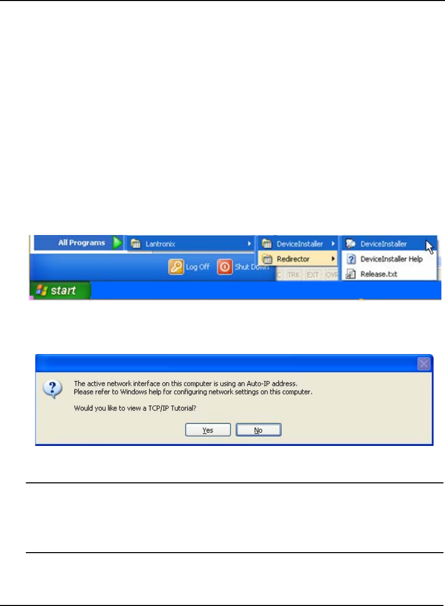
196 OEMV Family Installation and Operation User Manual Rev 5B
Appendix C Ethernet Configuration
11. Restart the laptop for the settings to take effect.
12. Power-off and then power-on the DL-V3. The Bluetooth mode is on again by default.
13. Issue the following commands, using Hyperterminal, to switch COM3 back to Ethernet and reset
the Ethernet device in the DL-V3:
APPCONTROL BLUETOOTH 1
APPCONTROL OPTION 12 1
14. Restart your laptop for the settings to take effect.
C.3.3 Configuring Ethernet Serial and Network Parameters
The DL-V3’s Ethernet module is DHCP-enabled by default, see Section C.2, Configuration Overview
starting on Page 190.
The default serial settings are 9600 baud, 8 data bits, no stop bits, 1 parity bit, and no flow control. In
order to change these settings, use the DeviceInstaller utility. Select and click on DeviceInstaller from
the Start | All Programs | Lantronix | DeviceInstaller menu in Windows.
Follow these steps to use DeviceInstaller:
1. Click No if you see an information message asking if you would like to see a tutorial on TCP/IP.
If you click No, the Lantronix DeviceInstaller program window is visible.
1. We previously went through the TCP/IP settings in Section C.3.2, Windows XP Network
Settings starting on Page 191.
2. You can view the Window’s TCP/IP tutorials at any time by selecting Help and Support
from Window’s Start menu and then using its Search engine to find TCP/IP.
2. Click the Search button (with a magnifying glass icon) in the Lantronix DeviceInstaller program
window to commence a search for any available Ethernet devices. If a device is found, its IP
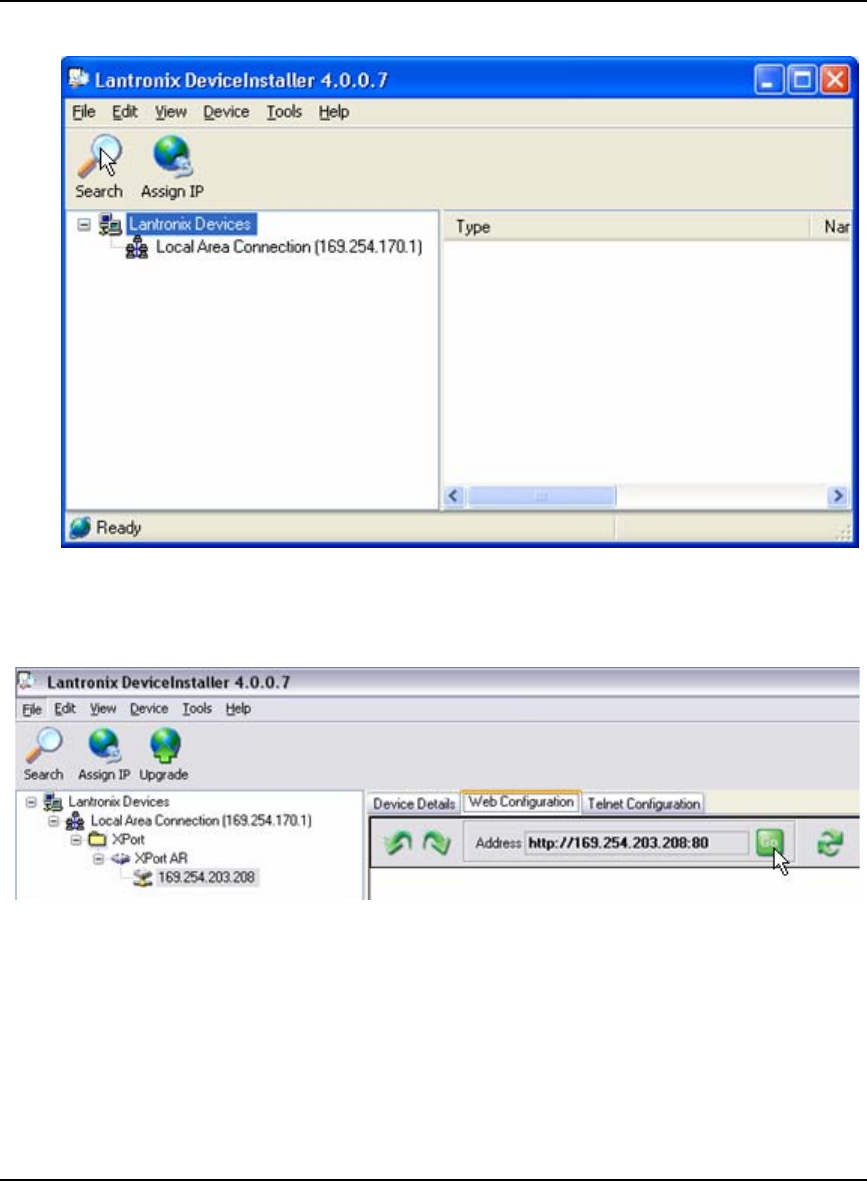
Ethernet Configuration Appendix C
OEMV Family Installation and Operation User Manual Rev 5B 197
address appears in a hierarchical tree found under Lantronix Devices.
3. Restart the laptop, select DeviceInstaller from the Start menu again and re-follow Steps 1 to 2
above. This time the Lantronix DeviceInstaller window should have a more detailed hierarchal
tree on the left and tabs to the right.
4. Select the Web Configuration tab and then click on the GO button found beside the Address field.
5. Enter the User Name as admin and the Password as PASS in the pop-up screen that appears.
6. Click OK to return you to the Lantronix DeviceInstaller window with a new Status menu to the
left of the right-side panel.
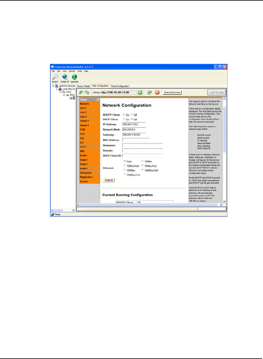
198 OEMV Family Installation and Operation User Manual Rev 5B
Appendix C Ethernet Configuration
C.3.3.1 Network Settings Configuration
Select Network| Configuration from the Status menu to change to the desired network settings.
Typically, the Ethernet device requires a static IP address, thus the DHCP Client is disabled. Also IP
Address, Network Mask, Gateway, Hostname, Domain, and Ethernet types are changed according to
the correct network values. Refer to an IT Network Administrator for further information, see also
Step 8 on Page 195. For instance, Figure 72 is an example of a private IP configuration:
Figure 72: Lantronix Device Installer: Network Configuration
Click on the Submit button for the network settings to be saved to the Ethernet device’s NVM.
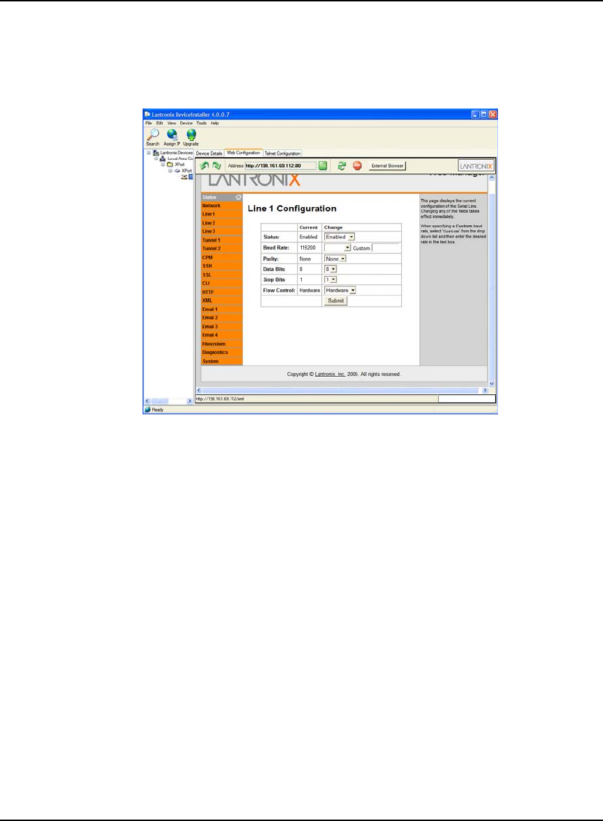
Ethernet Configuration Appendix C
OEMV Family Installation and Operation User Manual Rev 5B 199
C.3.3.2 Line 1 Configuration
Select Line 1 | Configuration from the Status menu. Line 1 refers to COM1 of the Ethernet device.
This is the port that is connected to COM3 of the DL-V3. Change the settings to match COM3 of the
DL-V3. The screen shown in Figure 73 displays the new settings:
Figure 73: Lantronix Device Installer: Line 1 Configuration
Click the Submit button for the Line 1 configuration to be saved to the Ethernet device’s NVM.
115200
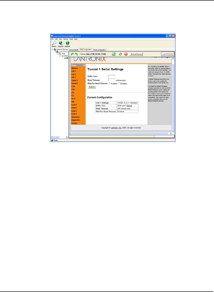
200 OEMV Family Installation and Operation User Manual Rev 5B
Appendix C Ethernet Configuration
C.3.3.3 Tunnel 1 Serial Settings
Select Tunnel 1| Serial Settings from the Status menu. Tunnel 1 is associated with Line 1 and must be
enabled. The screen in Figure 74 displays the current configuration:
Figure 74: Lantronix Device Installer: Tunnel 1 Serial Settings
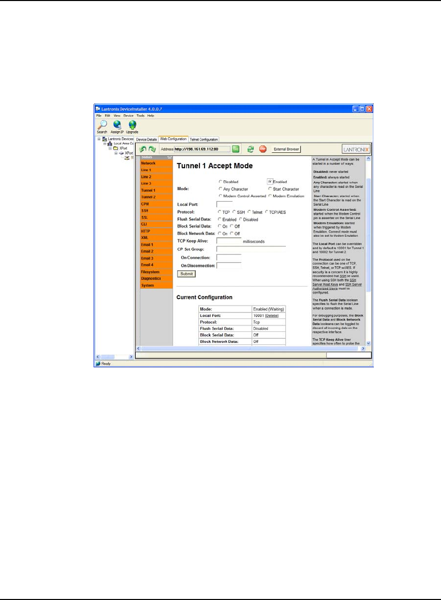
Ethernet Configuration Appendix C
OEMV Family Installation and Operation User Manual Rev 5B 201
C.3.3.4 Tunnel 1 Accept Mode
Select Tunnel 1 | Accept Mode from the Status menu. In order for the Ethernet device to transfer serial
data, Accept Mode must be enabled. That is, any data arriving at the Ethernet device’s serial port
automatically enables a TCP/IP connection. Refer to the Lantronix XPORT-AR User Guide, available
from their website, for further information. The screen in Figure 75 displays the Accept Mode
configuration:
Figure 75: Lantronix Device Installer: Tunnel 1 Accept Mode
Ensure that the Enabled radio button is selected and click on the Submit button to save the Accept
Mode to Ethernet device’s flash memory.
A pop-up warning may appear regarding the enabling of Accept Mode. Click OK.
202 OEMV Family Installation and Operation User Manual Rev 5B
Appendix C Ethernet Configuration
C.3.3.5 Reboot the XPORT-AR device
Select System from the Status menu. Click on the Reboot button to reboot the Ethernet device, and for
the network and serial settings to take effect. The screen in Figure 76 displays the system screen:
Figure 76: Lantronix Device Installer: System Screen
The Ethernet device is now ready to communicate with the DL-V3. In order for a client to
communicate with the Ethernet device using existing communications tools such as HyperTerminal,
the Ethernet device’s IP address must be mapped to a virtual serial port within the Lantronix Port
Redirector utility. Section C.3.4, Lantronix Port Redirector Software, starting below, describes the
configuration process.
C.3.4 Lantronix Port Redirector Software
Run the Lantronix Port Redirector software from the Start | All Programs | Lantronix | Redirector
menu.
The main Lantronix Redirector Configuration screen appears, see Figure 77 on Page 203.
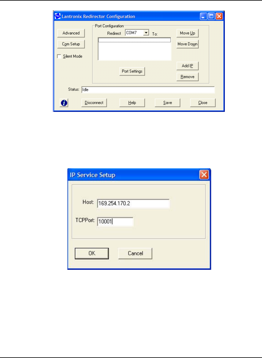
Ethernet Configuration Appendix C
OEMV Family Installation and Operation User Manual Rev 5B 203
Figure 77: Lantronix Redirector Configuration Dialog
C.3.4.1 Add the DL-V3 Ethernet Device’s IP Address and Port
Click on the Add IP button. The IP Service Setup screen appears. Figure 78 is an example using the
same IP address as configured in the Lantronix DeviceInstaller utility.
Figure 78: Lantronix Port Redirector: IP Service Setup
In the Host field, key in the DL-V3 Ethernet device’s IP address. Since the IP address is unique for
each installation, it is left up to the user to configure a valid IP address, typically static. For the port
setting, in the TCPPort field use 10001. Click OK to return you to the main Lantronix Redirector
Configuration dialog shown in Figure 77.
See also Section C.3.3.1, Network Settings Configuration on Page 198 and Section C.2, Configuration
Overview on Page 190.
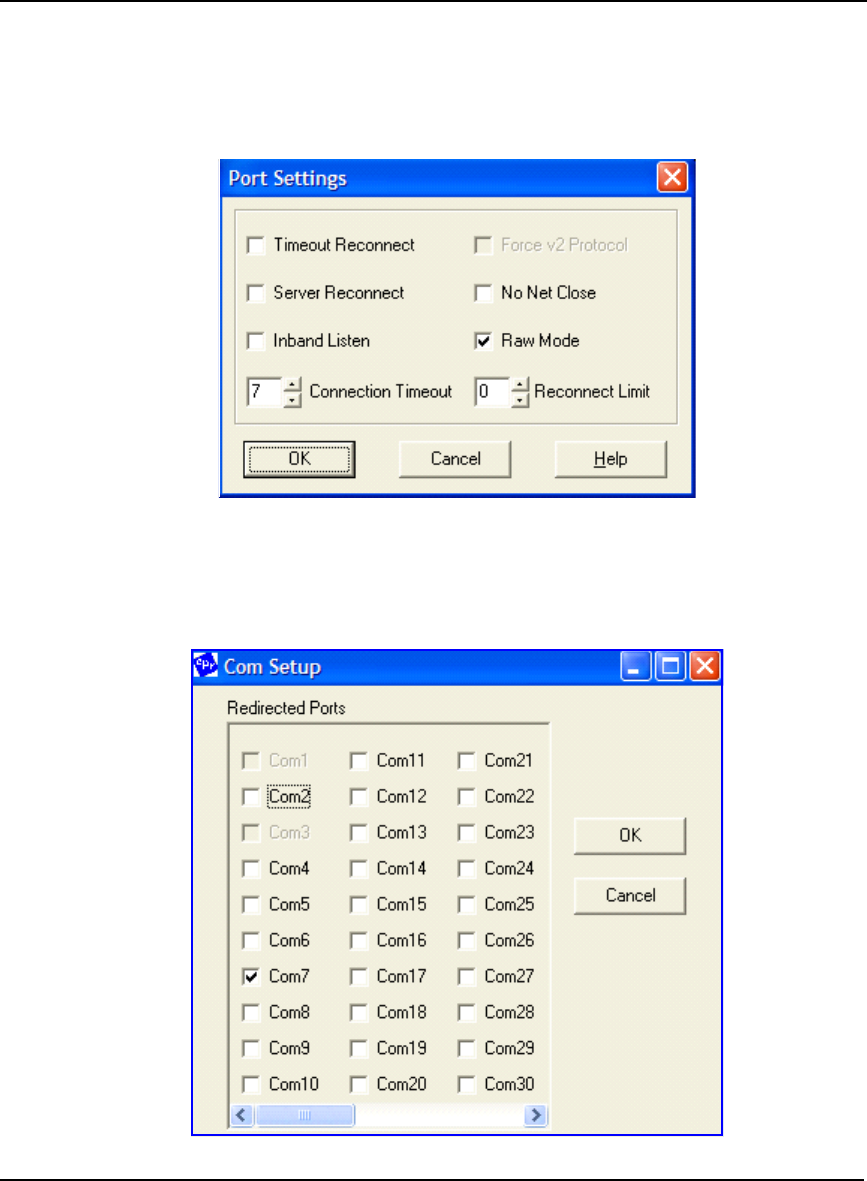
204 OEMV Family Installation and Operation User Manual Rev 5B
Appendix C Ethernet Configuration
C.3.4.2 Configure Port Settings
In the Lantronix Redirector Configuration dialog, click on the Port Settings button. The Port Setting
dialog appears as shown in Figure 79. Check the Raw Mode check box. Click OK to return you to the
main Lantronix Redirector Configuration dialog shown in Figure 77 on Page 203.
Figure 79: Lantronix Port Redirector: Port Settings Screen
C.3.4.3 Configure Virtual Serial Port
In the Lantronix Redirector Configuration dialog, click on the Com Setup button.
Figure 80: Lantronix Port Redirector: Com Setup Screen

Ethernet Configuration Appendix C
OEMV Family Installation and Operation User Manual Rev 5B 205
The Com Setup dialog appears, see Figure 80 on Page 204. Select a COM port to use as the virtual
serial port for the Ethernet device. Notice that you are unable to select previously assigned ports.
Click OK to return you to the main Lantronix Redirector Configuration dialog.
C.3.4.4 Redirector Configuration Completion
After completing the steps in the three sections from Section C.3.4.1 on Page 203 through to Section
C.3.4.3 above, click the Save button in the Lantronix Redirector Configuration dialog, shown in
Figure 77 on Page 203, and follow the prompts. Click the Close button to close the Redirector
program. The Windows system may require a reboot when a new COM port is selected.
The system is now ready to be used with HyperTerminal, CDU, or other serial communications
software. Ensure that the serial settings are identical to those configured for the Ethernet device, that
is 115200 baud, 8 data bits, no stop bits, 1 parity bit, no flow control and the same PC COM port as
selected in Section C.3.4.3, Configure Virtual Serial Port on Page 204.
C.4 Alternative Serial and Network Parameters Configuration
The DL-V3’s Ethernet port is Dynamic Host Configuration Protocol DHCP-enabled by default, see
Section C.2, Configuration Overview on Page 190. Also, the default serial settings are 9600 baud, 8
data bits, no stop bits, 1 parity bit, and no flow control.
Serial Command Mode is an alternative method to configure the Ethernet network and serial settings.
This method is complicated by the fact that there is no direct access to the Ethernet device because it
is an embedded part connected internally to COM3. The following paragraphs describe the detailed
process of configuring the Ethernet via the Serial Command Mode.
C.4.1 Physical Connections
To physically connect the Ethernet to the DL-V3, follow these steps:
1. Connect a serial null-modem cable from your Laptop to the DL-V3 COM1 port
2. Connect a serial null-modem cable from your Laptop to the DL-V3 COM2 port
1 serial null-modem cable may be connected from the laptop and switch between COM1 and
COM2 on the DL-V3. You can avoid switching if you have two serial connections on your
laptop and two null-modem cables. Also, if your laptop has only USB connectors, you need a
USB to serial adaptor between the null-modem cable and the laptop’s USB connector.
3. Connect the power cable to DL-V3 power port, power and switch on the unit with the button
on its front.
C.4.2 PC Software
HyperTerminal communications software is recommended for COM1 communications to the DL-V3.
From Window’s Start menu, select Programs | Accessories | Communications | Hyperterminal. The

206 OEMV Family Installation and Operation User Manual Rev 5B
Appendix C Ethernet Configuration
default communications parameters should be set to those listed in the following table in
Hyperterminal:
COM1 is used to tunnel to COM3 to gain direct access to the Ethernet.
COM2 is used to issue NovAtel commands to the DL-V3 using HyperTerminal communications
software. The communications parameters should be set to the defaults for DL-V3 COM2. Typically,
9600, 8, N, 1, no parity and local echo on.
C.4.3 DL-V3 Commands
C.4.3.1 Switch to Ethernet Device
Once communication has been established between your laptop serial port (or USB port with a USB-
to-serial port adaptor) and COM2 on the DL-V3, enter the following commands:
• LOG VERSION
Record the OEMV-3 part serial number (PSN) for future use (associated with the Ethernet
Media Access Control (MAC) address).
• APPCONTROL BLUETOOTH 1
Switch COM3 peripheral to Ethernet. On the front of the DL-V3, the Bluetooth LED no
longer glows blue but instead the Ethernet LED glows orange.
• LOG COMCONFIG
COMCONFIG shows you the current port settings (the default baud setting for COM3 is
115200). The COM commands below ensure both COM1 and COM3 are set to 9600 baud.
• COM COM1 9600 N 8 1
Parameter Setting
BAUD 9600
DATA BITS 8
PARITY N
STOP BITS 1
FLOW CONTROL NONE
ASCII SETTINGS Disable echo typed characters locally

Ethernet Configuration Appendix C
OEMV Family Installation and Operation User Manual Rev 5B 207
• COM COM3 9600 N 8 1
• LOG COMCONFIG
The COMCONFIG command should verify that COM3 is now set to 9600 baud.
C.4.3.2 Establish a Communications Tunnel
Still on COM2, enter the following commands:
• INTERFACEMODE COM3 TCOM1 NONE OFF
• INTERFACEMODE COM1 TCOM3 NONE OFF
C.4.3.3 Reset Ethernet
Still on COM2, enter the following command:
• APPCONTROL OPTION 12 1
This command forces the Ethernet to reset. Wait only a second for the Ethernet to power up again.
C.4.3.4 Establish Serial Command Mode in Ethernet
Switch the null-modem cable connection on the DL-V3 from the COM2 port to the COM1 port.
Follow this procedure very carefully.
1. Select File | Properties in the HyperTerminal menu. The Connections Properties dialog appears.
2. Click on the Settings tab in the Connections Properties dialog.
3. Click on the ASCII Setup button in the Settings tab. The ASCII Setup dialog appears.
4. Ensure that the Echo typed characters locally check box is unchecked. Normally it is useful to see
what you are typing but for the following step we are only interested in what the Ethernet device
returns to the screen.
5. Click on the OK buttons until you return to the main HyperTerminal window.
6. Type the character ‘!’ and wait for a returned ‘!’ character to appear. If it does not, repeat entering
the ! and continue until a ! is returned to the screen. Immediately after observing the ! character
returned, type:
• xyz
1. Do not hit the Enter key after typing the z, simply wait for the prompt to appear
2. If the ! character never appears, go back to step C.4.3.3.
7. Follow steps 1 through 3 above again and then go on to step 8 now that we are typing commands
again, and want to see characters as we type them.

208 OEMV Family Installation and Operation User Manual Rev 5B
Appendix C Ethernet Configuration
8. Ensure that the Echo typed characters locally check box is checked this time.
9. Click on the OK buttons until you return to the main HyperTerminal window.
10. Enter the following command in the main window (that is in Command Mode)
• enable
Figure 81 shows an example of the Ethernet communication in command mode. The xyz and
enable commands can be seen near the top. The other commands that follow are shown in the
next section. Refer back to Figure 81, as you follow the next section’s instructions, to see if you
get the expected results. If not return to step C.4.3.3 and try again.
Figure 81: Command Mode Example
char *acCmds[] =
{ // expect:
"xyz", // >
"enable\r", // (enable)#
"configure\r", // (config)#
"if 1\r", // (if-1)#
"ip address ", // (if-1)#
"no dhcp\r", // (if-1)#
"speed auto\r", // (if-1)#
"write\r", // (if-1)#
"exit\r", // (config)#
"exit\r", // (enable)#
"line 1\r", // (line-1)#
"databits 8\r", // (line-1)#
"flowcontrol hardware\r", // (line-1)#
"speed 115200\r", // (line-1)#
"write\r", // (line-1)#
"exit\r", // (enable)#
"reload\r", // Are you sure (yes/no)
?
"yes\r", // Rebooting...
0
};

Ethernet Configuration Appendix C
OEMV Family Installation and Operation User Manual Rev 5B 209
C.4.4 Network Configuration in Command Mode
1. Text within brackets < > denote optional parameters.
2. An IP address must be formatted in dotted quad IP address notation and be valid for the
network. An example of dotted quad notation is: 192.168.0.254
3. Refer to the Lantronix XPORT-AR User Guide for a full command set. Lantronix website
details are on Section C.1, Physical Set-Up on Page 189.
11. (continued from Page 208) Enter the following Ethernet command-mode commands on COM1,
to configure the network settings:
• show
1. Record the MAC address. It should appear as a set of six hexadecimal value pairs
separated by colons. For example:
00:20:4A:44:55:66
2. The show command is not shown in Figure 81 on Page 208.
• configure
• if 1
• ip address <IP> <network mask>
• ip default-gateway <gateway IP address>
• no dhcp
• speed auto
• exit
• exit
• write
• line 1
• databits 8
• flowcontrol hardware
• speed 115200
12. Change the baud rates to re-establish communications with the Ethernet device now that the
Ethernet is set to 115200, but the tunneled serial ports on the DL-V3 are still at 9600 baud. In
addition, HyperTerminal’s baud rate is also still set to 9600.
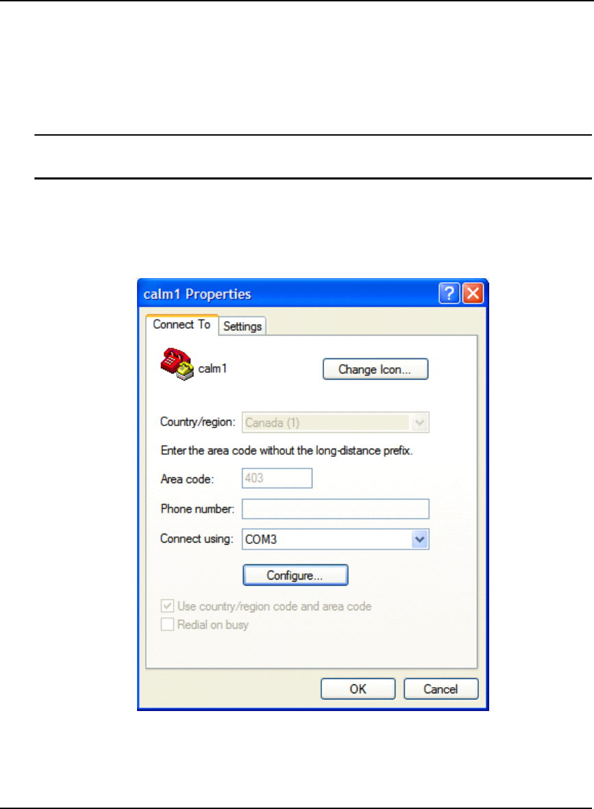
210 OEMV Family Installation and Operation User Manual Rev 5B
Appendix C Ethernet Configuration
13. Switch the null-modem cable connection on the DL-V3 from the COM1 port to the COM2 port.
14. Enter the following commands on COM2:
• COM COM1 115200
• COM COM3 115200
• LOG COMCONFIG
The COMCONFIG command verifies that the baud rate on COM1 and COM3 are now
115200.
15. Select Call | Disconnect from the main menu to disconnect the communications so that a new
baud rate can be configured.
16. Choose File | Properties from the main menu.
17. Click on the Configure... button in the Properties dialog.
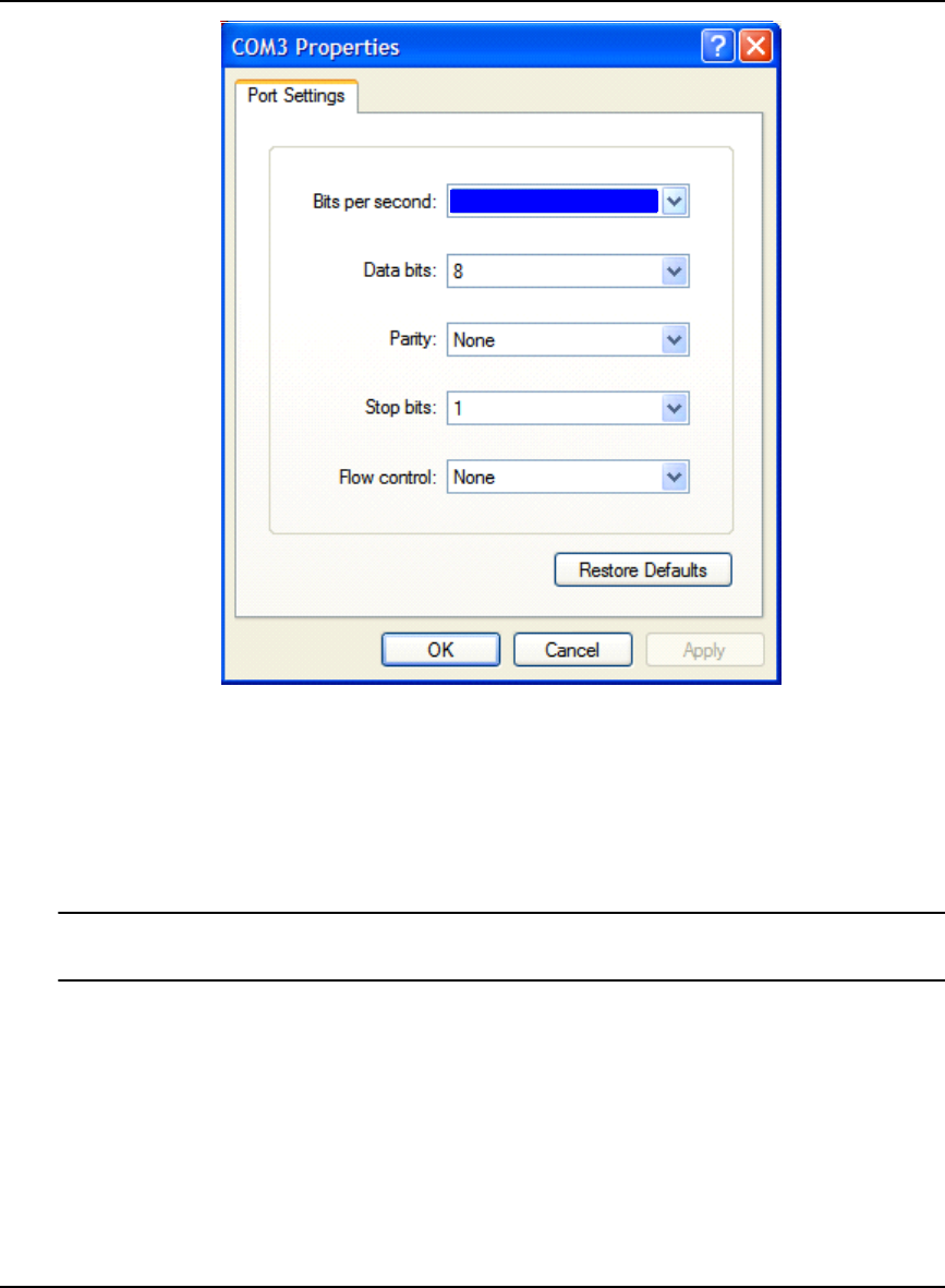
Ethernet Configuration Appendix C
OEMV Family Installation and Operation User Manual Rev 5B 211
18. Choose 115200 in the Bits per second: field.
19. Click OK.
20. Switch the null-modem cable connection on the DL-V3 from the COM2 port to the COM1 port.
21. Re-connect HyperTerminal and type the following commands to COM1:
• exit
Type YES when asked to reboot or reload the system. For example, after you see:
reload\r
• yes
22. Switch the null-modem cable connection on the DL-V3 from the COM1 port to the COM2 port
23. Type RESET on COM2, or push and hold the power button on the DL-V3 and wait for the LEDs
to indicate that the unit is powering off before releasing the power button, or physically remove
power from the DL-V3. This step restores COM1 and COM3 by resetting the unit.
This concludes the Ethernet configuration via Serial Command Mode. Next, see the Lantronix Port
Redirector Software section starting on Page 202 to configure Lantronix Port-Redirector software to
configure a Lantronix virtual serial port in Windows XP.
115200

212 OEMV Family Installation and Operation User Manual Rev 5B
Appendix D Replacement Parts
The following are a list of the replacement parts available for your NovAtel GPS receiver. Should you
require assistance or need to order additional components, please contact your local NovAtel dealer or
Customer Service representative.
D.1 DL-V3 and ProPak-V3
D.2 ProPak-V3
D.3 FlexPak-V2, FlexPak-V1G and FlexPak-V1
D.4 Accessories
Part Description NovAtel Part
I/O strobe cable (Figure 63 on Page 169) 01017660
Straight through serial data cable (Figure 62 on Page 168) 01017659
Null modem serial data cable (Figure 61 on Page 167) 01017658
Power cable: LEMO 4-pin socket to 12V power outlet plug (Figure 60 on Page 166) 01017663
Part Description NovAtel Part
USB serial cable (Figure 64 on Page 170) 01017664
Part Description NovAtel Part
12V power adapter cable (Figure 65 on Page 175) 01017821
13-pin Deutsch to DB9 null modem serial cable (Figure 66 on Page 176) 01017822
13-pin Deutsch to DB9 straight through cable (Figure 67 on Page 177) 01017823
13-pin Deutsch to USB connector cable (Figure 68 on Page 178) 01017820
Part Description NovAtel Part
OEMV Family Compact Disc with PC utilities 01017716-VER1
OEMV Family Installation and Operation User Manual OM-20000093
OEMV Family Firmware Reference Manual OM-20000094
SMART-V1 multi-cable USB (2 DB-9, 1 USB and 7 bare tagged wire ends) 01017983
SMART-V1 multi-cable CAN (3 DB-9, and 7 bare tagged wire ends) 01017984
SMART-V1 multi-cable USB variant (all bare tagged-wire ends) 01017923
SMART-V1 multi-cable CAN variant (all bare tagged-wire ends) 01017922
Optional NovAtel Antennas: Model 702 (L1/L2) GPS-702
Model 701 (L1-only) GPS-701
Model 702L (L1/L2/L-Band) GPS-702L
Model 702GG (L1/L2/GLONASS) GPS-702GG
Model 701GG (L1/GLONASS) GPS-701GG
Model 702GGL (L1/L2/GLONASS/L-Band) GPS-702GGL
Model 701GGL (L1/GLONASS/L-Band) GPS-701GGL
Model 538 (L1/GLONASS/L-Band) ANT-538
Continued on Page 213

Replacement Parts Appendix D
OEMV Family Installation and Operation User Manual Rev 5B 213
D.5 Manufacturers’ Part Numbers
The following original manufacturer’s part numbers are provided for information only and are not
available from NovAtel as separate parts:
Model 534 (L1/L2/L-Band) ANT-534
Model 533 (L1/L2) ANT-533
Model 532 (L1/L2) ANT-532
Optional RF Antenna Cable: 5 meters C006
15 meters C016
30 meters C032
22 cm interconnect adapter cable GPS-C002
AC Adapter 120/240VAC 15 Watts, 12 V DC adapter with USA electrical chord 40023098
Part Description NovAtel Part
Product Part Description Company Part Number
ProPak-V3/DL-V3
Power Cable
(Figure 60 on Page 166)
4-pin socket connector LEMO FGG.0B.304.CLAD52Z
FlexPak-V1/V1G/V2
Cables (Figures 65 -68
starting on Page 175)
3-pin plug connector on 12V power
adapter cable DEUTSCH 59064 - 09 - 98SN
13-pin plug connector on serial cables DEUTSCH 59064 - 11 - 35SF
SMART-V1, USB or
CAN Model Cables 18-pin plug connector on multi-cable Switchcraft EN3C18F26
OEMV-1 Card/OEMV-
1G Card
(Figure 47 on Page 130)
J100 - MCX JACK RECEPTACLE
RF signal input and LNA power output JOHNSON 133-3701-211
J700 - 2x10 HEADER, 2mm PITCH
Power, data, and signal connector SAMTEC TMM-110-03-TM-D
OEMV-2 Card
(Figure 51 on Page 142)J100 - MMCX JACK RECEPTACLE
RF signal input and LNA power output JOHNSON 135-3701-201
J501 - MMCX JACK RECEPTACLE
External oscillator input JOHNSON 135-3701-201
P1101 - 2x12 HEADER, 2mm PITCH
Power, data, and signal connector SAMTEC TMM-112-03-L-D
OEMV-3 Card
(Figure 53 on Page 148)
Note the alternates for
J100 and J700.
J100 - MMCX JACK RECEPTACLE
RF signal input and LNA power output JOHNSON 135-3701-201
HUBER+SUHNER 82 MMCX-50-0-1
J700 - MMCX JACK RECEPTACLE
External oscillator input JOHNSON 135-3701-201
HUBER+SUHNER 82 MMCX-50-0-1
P1601 - 2x20 HEADER, 0.1" PITCH
Power, data, and signal connector SAMTEC TSM-120-01-S-DV
P1400 - 2x7 HEADER, 0.1" PITCH
CAN Bus with transceiver SAMTEC TSM-107-01-L-DV

214 OEMV Family Installation and Operation User Manual Rev 5B
Index
A
access door, 53
accuracy
base station, 83
decrease in, 98
positioning, 75, 77, 83–84, 91, 129
RT-2 and RT-20, 92, 94–95, 129
acquisition, 20
AdVance RTK, 92
aerial photograph, 91
ambiguity
fixed, 91
floating, 94
resolution, 92, 97
antenna
active, 31, 33, 52
cables, 34, 213
card status, 118, 120
considerations, 39
dual-frequency, 33
height, 64
input, 156, 163, 171
models, 33, 212
power, 32, 52, 154
single-frequency, 33, 39
site, 78
anti-static, 36, 186–188
append a filename, 63
ascii, 66, 105
atmosphere, 83, 93
AUTH command, 113
authorization, 113
auxiliary status, 121
B
base station
accuracy, 92
differential, 63, 83
health, 98
height, 97
overview, 83
position, 75
baseline, 59
baud rate, 57
bidirectional communication, 57
binary, 66, 122
bluetooth, 26, 41, 43–44, 49, 156, 189
broadcast
corrections, 81, 91
ephemeris, 77
error word, 122
buffer, 57, 92, 98
C
cables, 170
antenna, 213
coaxial, 31, 33–34, 52
extended cable lengths, 34
null modem, 57
serial, 57
warranty, 17
CAN, see controller area network bus
carrier phase
differential positioning, 81
multipath errors, 93
cautions, 36, 45, 52, 57
CDGPS, 65, 85, 90
CDU software, 99, 212
channels, 118, 120
choke ring, 97
circuit board, 21, 188
clock
bias, 91
synchronization, 81
CMR, 92
CMRPLUS (CMR+), 90
coaxial, 31, 33–34, 52
cold start, 129
commands
antenna power, 52
default port settings, 57
in CDU, 103, 112
input, 59
L-Band, 90

Index
OEMV Family Installation and Operation User Manual Rev 5B 215
OEMV communication, 57
position averaging, 75
positioning, 133, 139, 145, 151
pre-configuring, 61
communication
bidirectional, 57
cable, 160, 167, 170, 176
port, 37
Compact Flash Card, 41, 52–54
configuration
additional equipment, 33
antenna, 34
differential, 84
overview, 20
port, 57
status, 118–119
typical hardware, 56
connector, 38–39
antenna, 131, 137, 143, 149, 156, 163,
171
COM, 171
input/output, 156, 163, 171, 179
power, 131, 137, 143, 149, 159, 166,
175
constellation, 97
control signals, 20
Controller Area Network Bus (CAN Bus),
46
Convert software, 105
copyright, 2
customer service, 93, 112
D
datacollection, 53, 63–64
DC antenna, 156, 163, 171
path, 31
power, 156, 163
dealer, 18, 112
default
bit rates, 131, 137, 144, 150
port settings, 57
differential
corrections, 75, 83–84, 98
positioning, 83
digital, 31, 158, 165
dilution of precision (DOP), 74, 81
directional communication, 57
distance, 91
dynamics, 20
E
eject button, 54
electrostatic discharge (ESD), 36, 186–188
elevation, 91, 93, 95
e-mail, 18
ephemeris
errors, 77, 83, 93, 97
errors
card status, 119–121
ephemeris, 77, 93, 97
ionospheric, 92–93
multipath, 93
trigger, 118
tropospheric, 93, 97
ESD, see electrostatic discharge
ethernet, 26, 41, 43–44, 49, 156, 189
event messages, 119–120
extended cable lengths, 34
external oscillator, 51, 143, 149
F
features, 19, 58, 112–113
filesname, 63
firmware reference marker, 119
firmware upgrades, 18, 112–113
fixed ambiguities, 91
flash-memory, 54
format a Compact Flash Card, 54
frequency
L1/L2, 91
measurements, 92
G
GEO, SBAS, 79
GLONASS, 20, 34, 106
GPSoverview, 77, 81–83, 91
time, 77
GPSAntenna, 17, 212
graphical user interface, 100

216 OEMV Family Installation and Operation User Manual Rev 5B
Index
ground plane, 97
H
handheld controller, 52
handshaking, 57
header, 121
health, 98
height
base station, 97
difference, 97
phase center, 83
rover station, 97
hexadecimal, 119, 123
I
I/O, 144, 150, 156, 158, 163, 165, 171
idle time, 57
impedance, 131, 137, 143, 149, 156, 163,
171
input
antenna, 156, 163, 171
commands, 59
event, 133, 139, 145, 151, 158, 165
installation, 19, 99
integration, 19
ionospheric, 77, 83, 92–93, 97
K
kinematic, 91, 96
L
latency
base station, 98
differential positioning, 82
extrapolation error, 82
RT-20 performance, 95
latitude, 83
L-Band, 85
antenna, 34
commands and logs, 90
enable, 65
service levels, 88
LED, 47, 118, 120, 122
LNA, see low noise amplifier
logging, 52, 63–64
logsCMR, 62, 92
CMRPLUS (CMR+), 90
in CDU, 104
L-Band, 90
position averaging, 75
positioning, 98
RTCA, 62
RTCM, 62
RTK, 93, 95
status, 118, 121
longitude, 83
loss of lock, 91
low noise amplifier (LNA), 32, 131, 137,
143, 149
LVTTL, 131, 137, 144, 150
M
mark input (MKI), 133, 139, 145, 151
messages
event, 119
MKI, see mark input
modem, 66
mounting, 37
multipath
antenna models, 33
interference, 81
reduction, 97
RT-2 performance, 93
N
Narrow Correlator tracking technology, 81
navigation
applications, 21
noise
reduction, 81
satellite pair, 91
Notices, 10, 12
NovAtel Inc., 2
null modem, 57
O
OCXO, see oscillators
offset, 81, 83, 91
OmniSTAR, 85
HP, 88

Index
OEMV Family Installation and Operation User Manual Rev 5B 217
VBS, 88
XP, 88
operation, 19, 56
oscillators, 51, 77–78, 143, 149
output
connector, 156, 163, 171, 179
data, 20
P
parity, 42, 57
pass-through logs, 66
PDOP, see dilution of precision
polarity, 35
ports
COM, 58
communication, 62
RXSTATUSEVENT log, 119
serial, 57
position
base station, 59
overview, 21
static, 91
power
button, 40
connector, 131, 137, 143, 149, 159, 166,
175
modes, 40
requirements, 131, 137, 143, 149
supply, 33
precision, 81
priority mask, 118, 121
processing circuitry, 31
propagation, 77
pseudorange
algorithms, 81
errors, 93
measurement, 78, 83, 91
positioning, 77, 81
solutions, 98
R
radio frequency (RF), 118, 120
antenna power supply, 52
GPSAntenna, 31
OEMV card section, 31
overview, 21
real-time
kinematic software, 92
receiver status, 118–119, 121
redirect data, 66
replacement parts, 212
reset, 120, 122
revision
firmware, 112
manual, 2, 219
RF, see radio frequency
Rinex, 105
root mean square (RMS), 95
rover station, 81
accuracy, 92
differential positioning, 62, 83
height, 97
RT-2 and RT-20, 92, 94–95
RTCM1819, 61, 92
RTCM2021, 92
RTCMV3, 61
RTK
filter, 98
logs, 93
messages vs. accuracy, 92
performance, 97
positioning, 91
radio, 57
S
satellite
antenna location, 40
records, number of, 57
tracking, 93, 95
transmit, 31
SBAS, 78, 80–81
self-test, 58
serial
cable, 57, 170
number, 112
port, 62
signals, 20
site information, 63
speed, 81
static, 186–188
status mask fields, 118
strobe signals, 37
support, 17–18
surveying, 21, 83

218 OEMV Family Installation and Operation User Manual Rev 5B
Index
T
TCXO, see oscillators
technical specifications, 129
tests (built-in), 118–119, 121–122
timestrobes, 37
synchronization, 71
tracking
loops, 91
loss, 98
satellites, 93, 95
trigger, 118
tropospheric, 77, 83, 93, 97
troubleshooting, 124
U
upgrade firmware, 18, 112–113
USB, 45
cable, 170
drivers, 108–109, 111
pass-through logging, 66
port, 59
signals, 135, 141, 147, 153
V
version, 113
voltage, 131, 137, 143, 149
W
wake up, 41
warnings, 10–11, 32–34, 52, 54
warranty, 17, 32, 37
website, 18
windows in CDU, 100–104
WinLoad, 113

OM-20000093 Rev 5B 2007/03/23