Novatel 01017829 GPS Receiver with Bluetooth User Manual Technical Writer
Novatel Inc GPS Receiver with Bluetooth Technical Writer
UserManual.wiki
>
Novatel
>
01017829 User Manual
>
User Manual part 2
Contents
1.
User Manual part 1
2.
User Manual part 2
User Manual part 2
Navigation menu
Upload a User Manual
Namespaces
Wiki Guide
HTML
PDF
Info
Views
User Manual
Discussion / Help
Navigation
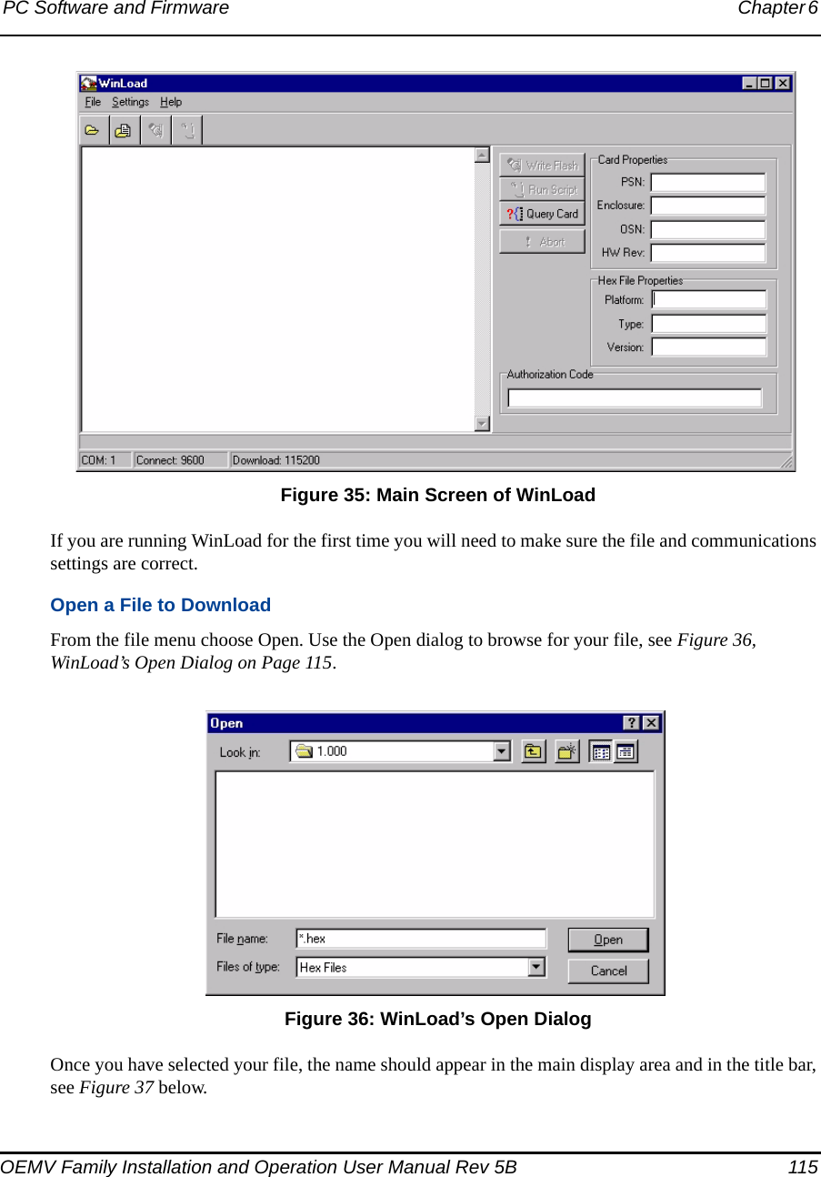
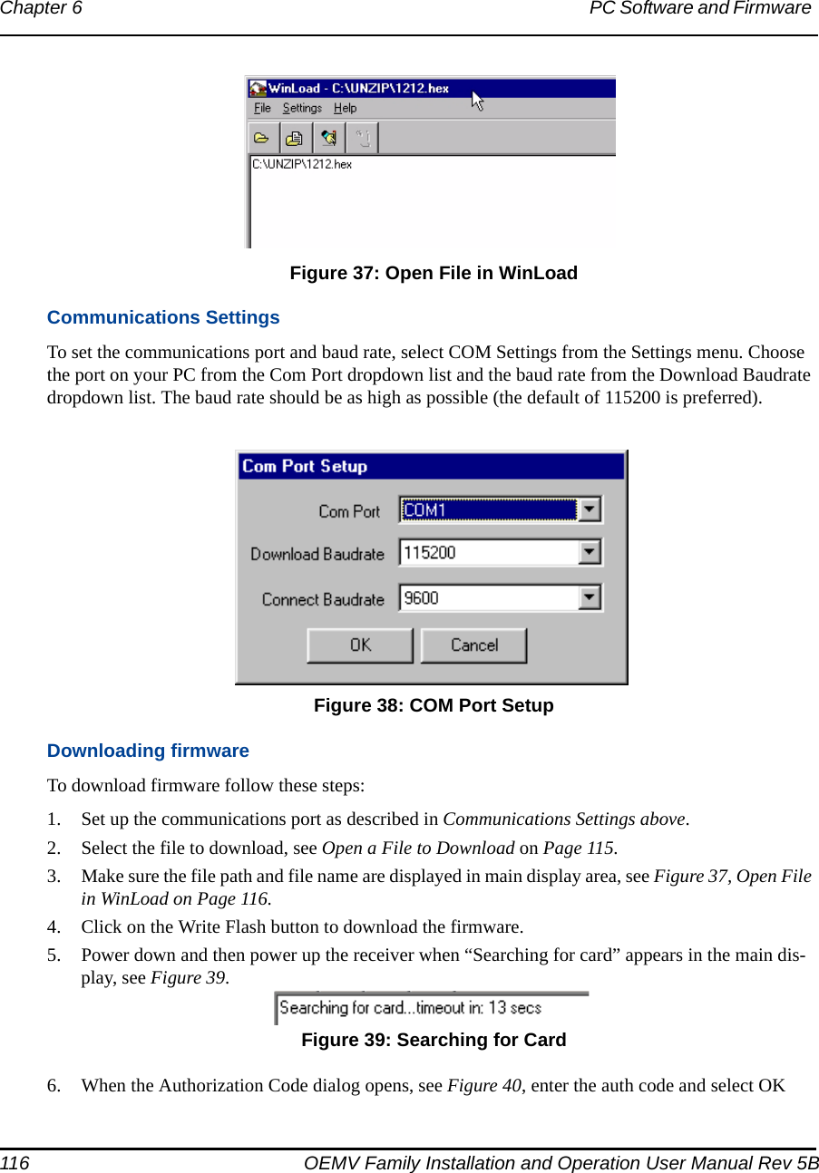
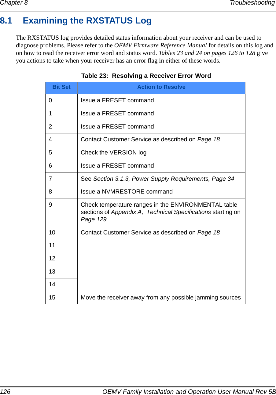
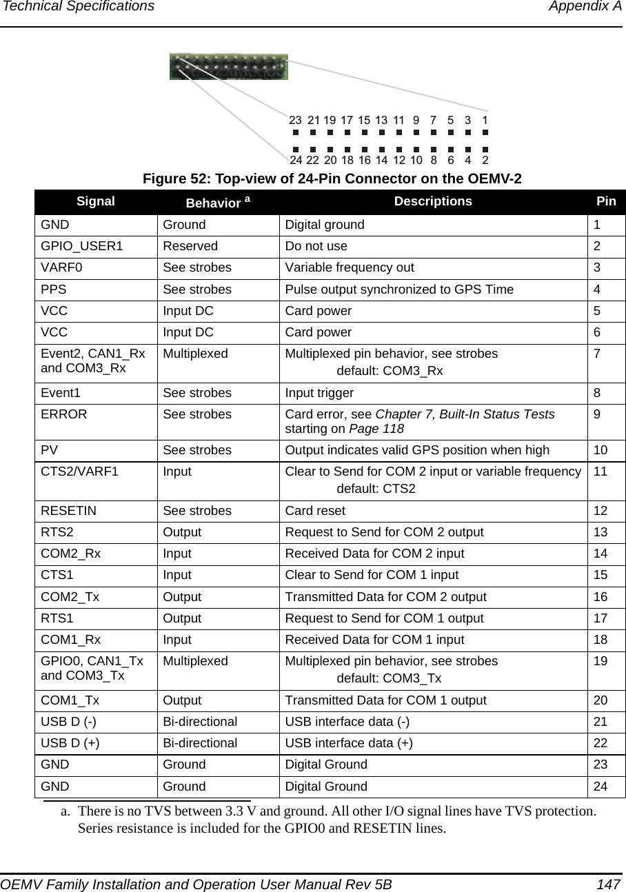
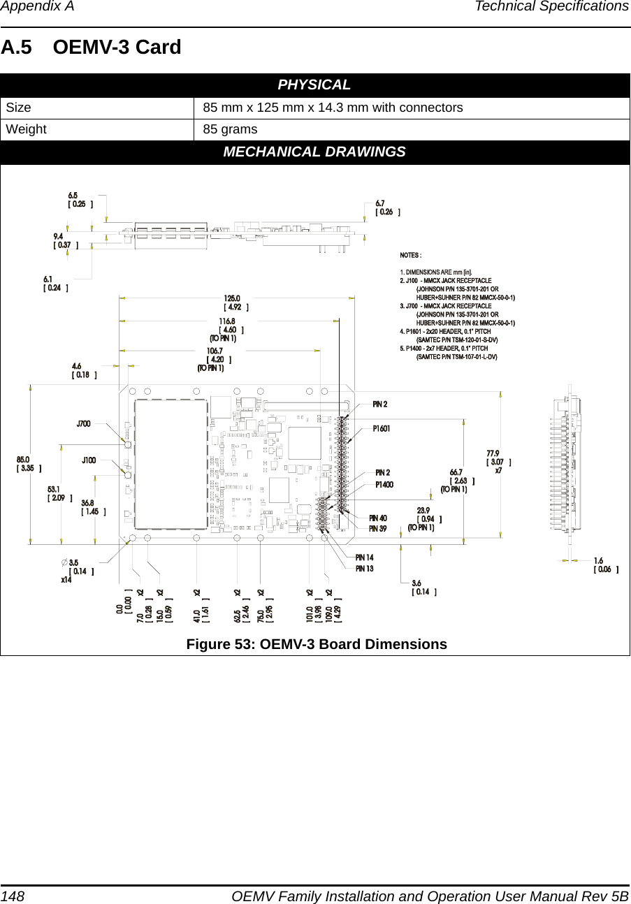
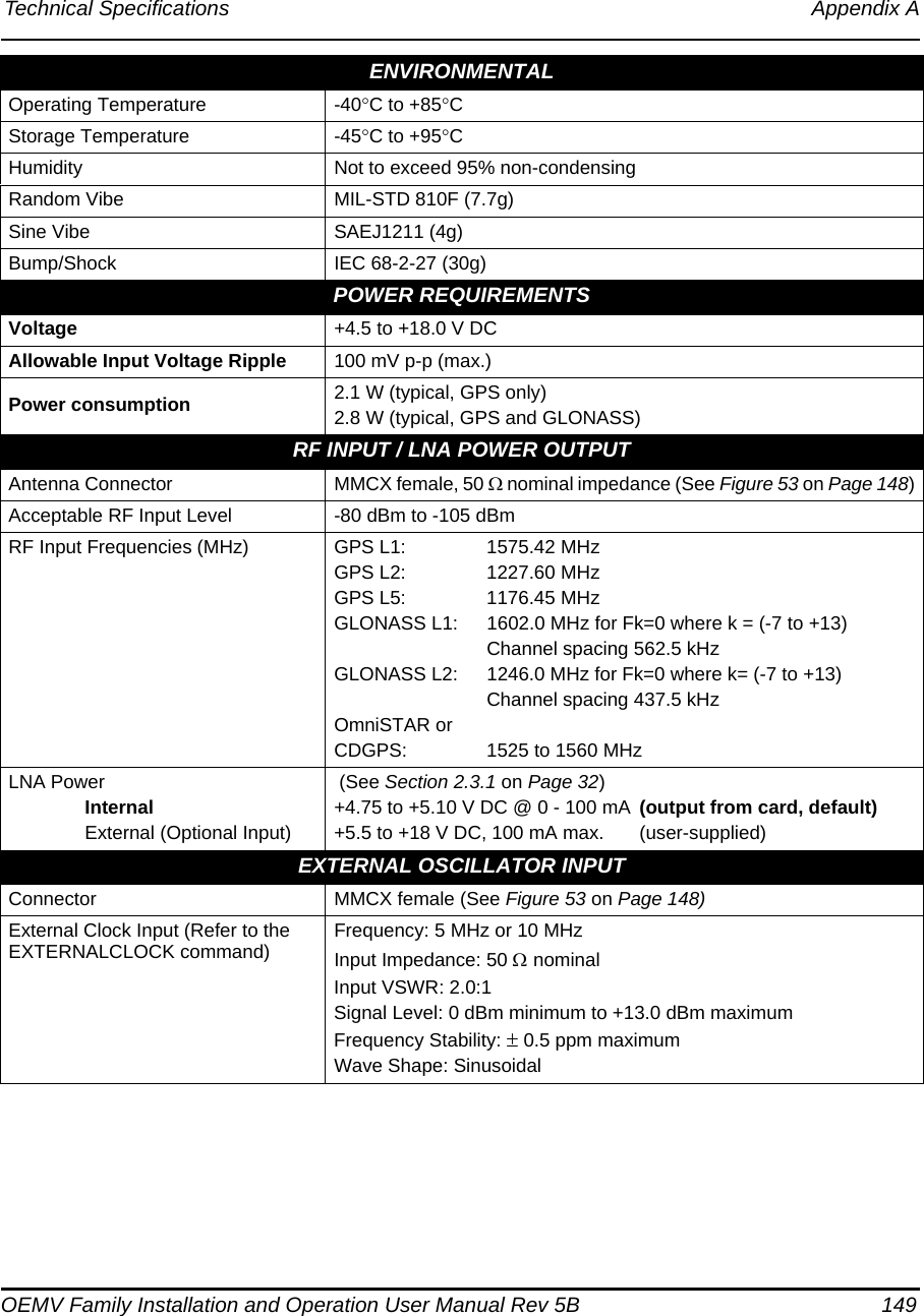
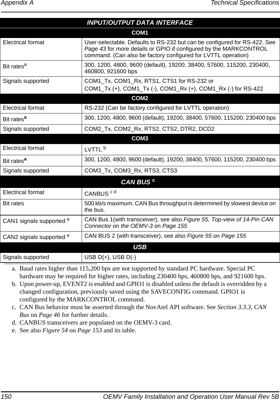
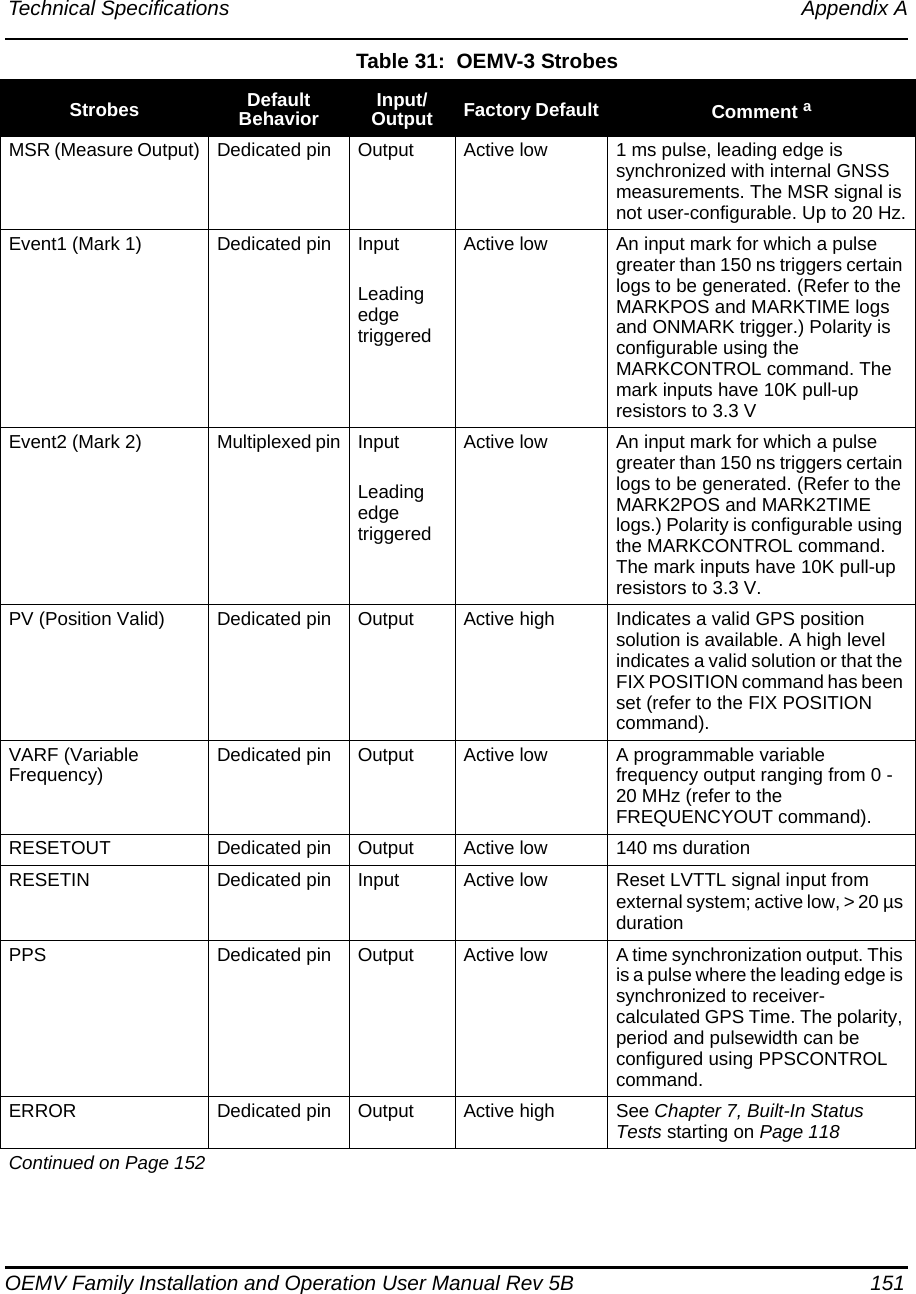
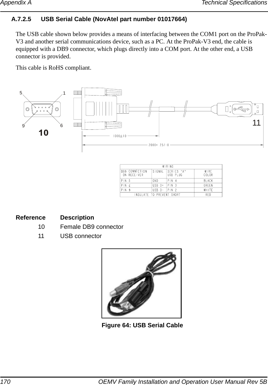
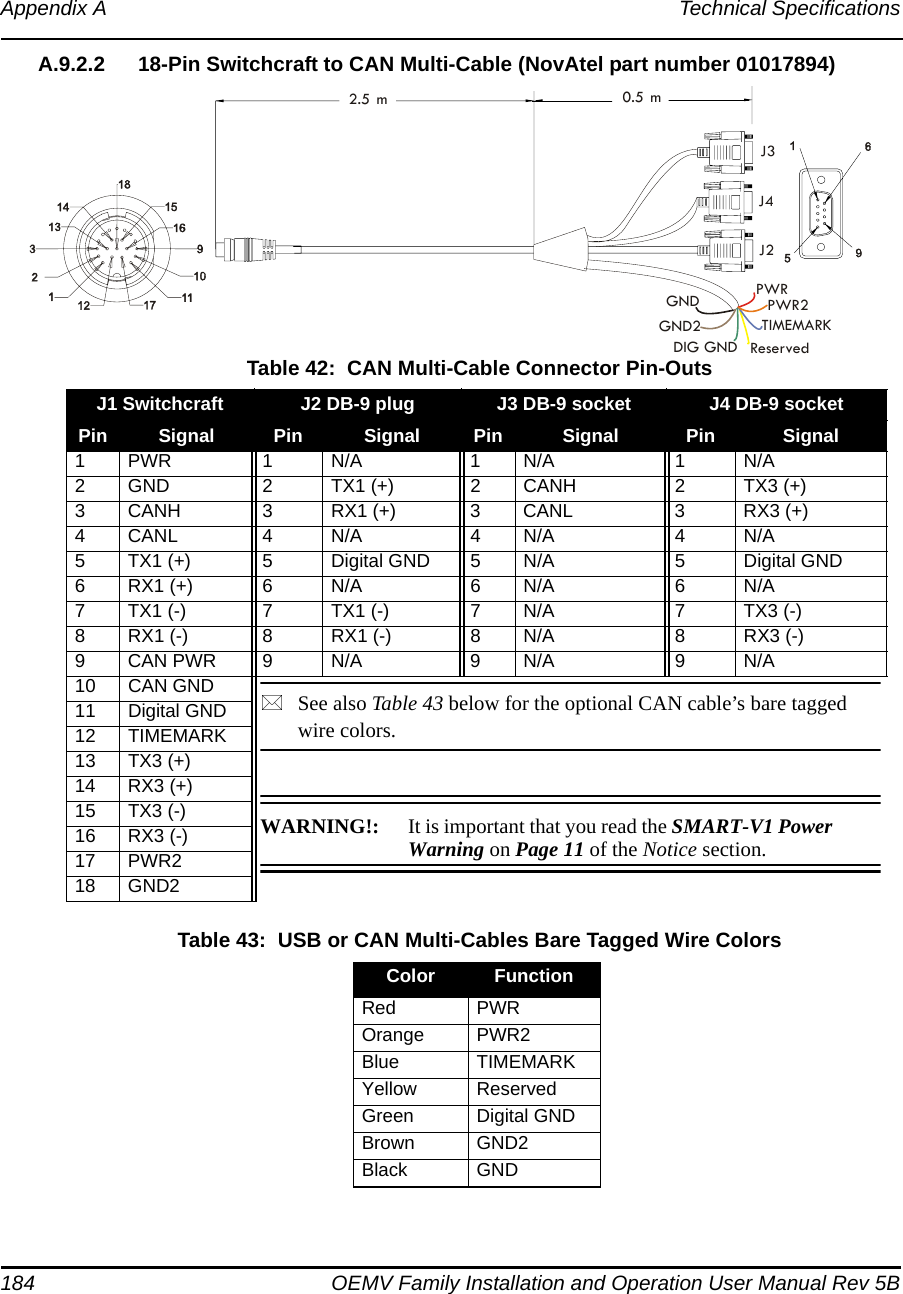
![114 OEMV Family Installation and Operation User Manual Rev 5BChapter 6 PC Software and Firmware more information on how to contact NovAtel Customer Service please see Page 18 at the beginning of this manual.You will need at least 1 MB of available space on your hard drive. For convenience, you may wish to copy this file to a GPS sub-directory (for example, C:\GPS\LOADER).The file is available in a compressed format with password protection; Customer Service will provide you with the required password. After copying the file to your computer, it must be decompressed. The syntax for decompression is as follows:Syntax:[filename] [password]where filename is the name of the compressed file (but not including the .EXE extension) and password is the password required to allow decompressionExample:oem1001 12345678A windows-based dialog box is provided for password entry.The self-extracting archive will then generate the following files:WinLoad.exe WinLoad utility programHowTo.txt Instructions on how to use the WinLoad utilityWhatsNew.txt Information on the changes made in the firmware since the last revisionXXXX.hex Firmware version upgrade file, where XXXX = program version level (for example, 1001.hex)Using the WinLoad UtilityWinLoad is a windows based program used to download firmware to OEMV family cards. The main screen is shown in Figure 35.](https://usermanual.wiki/Novatel/01017829.User-Manual-part-2/User-Guide-777995-Page-6.png)
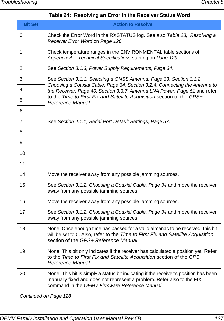


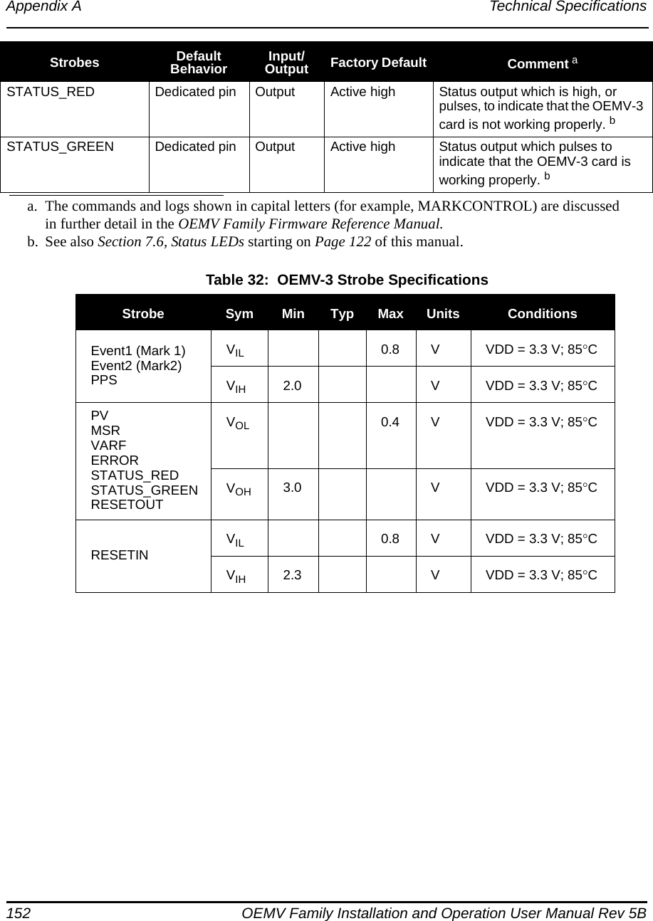

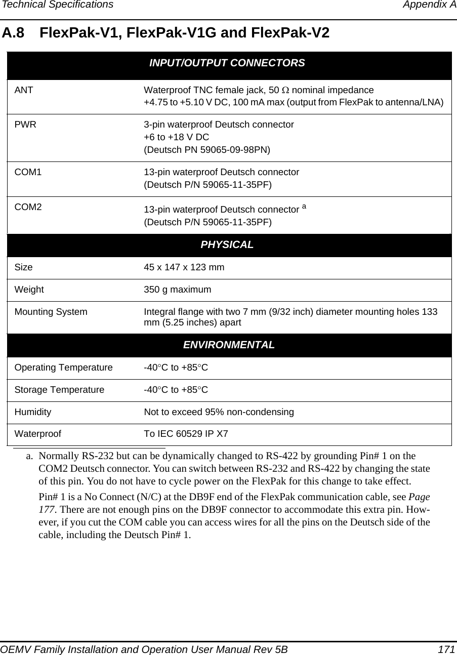

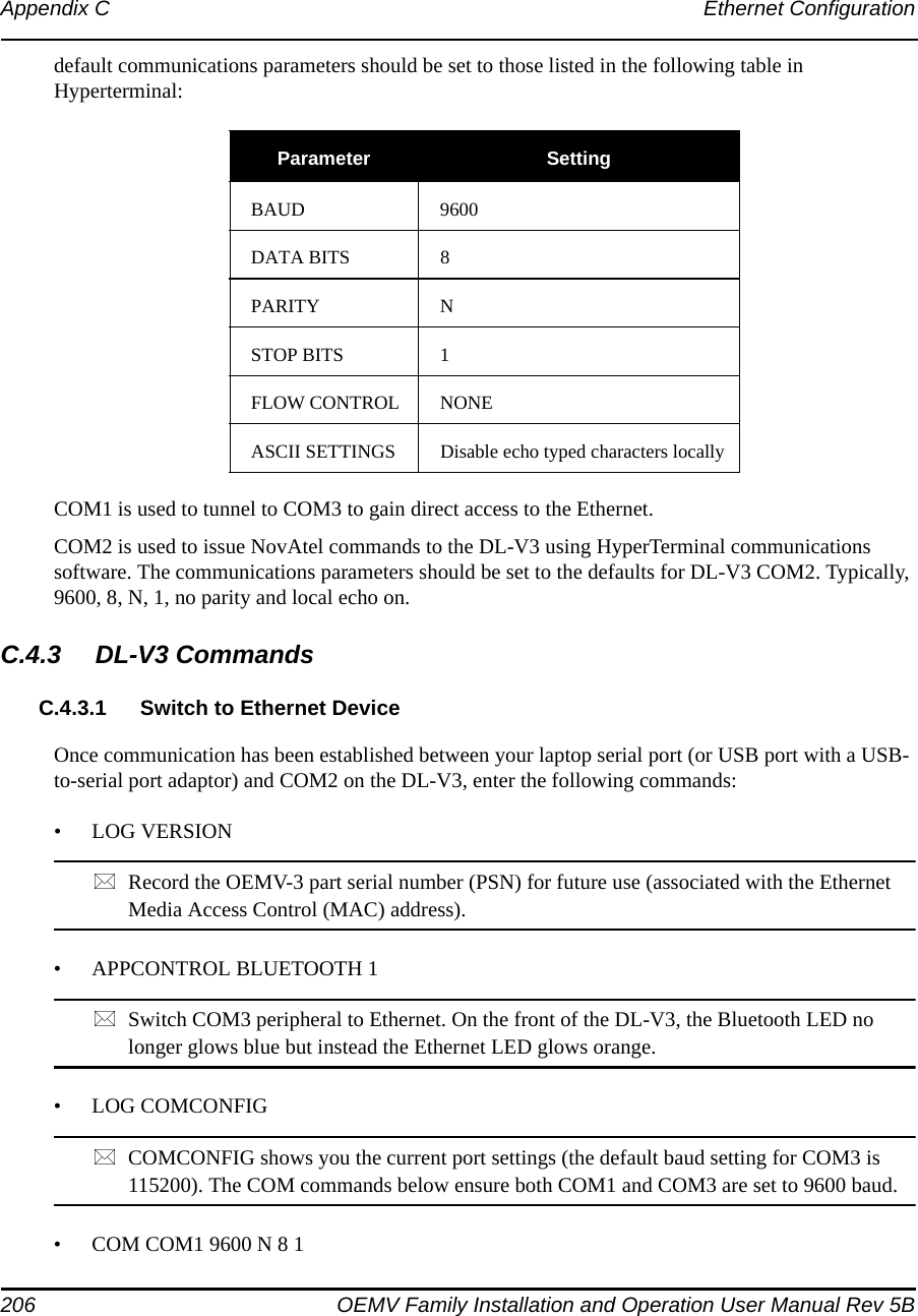
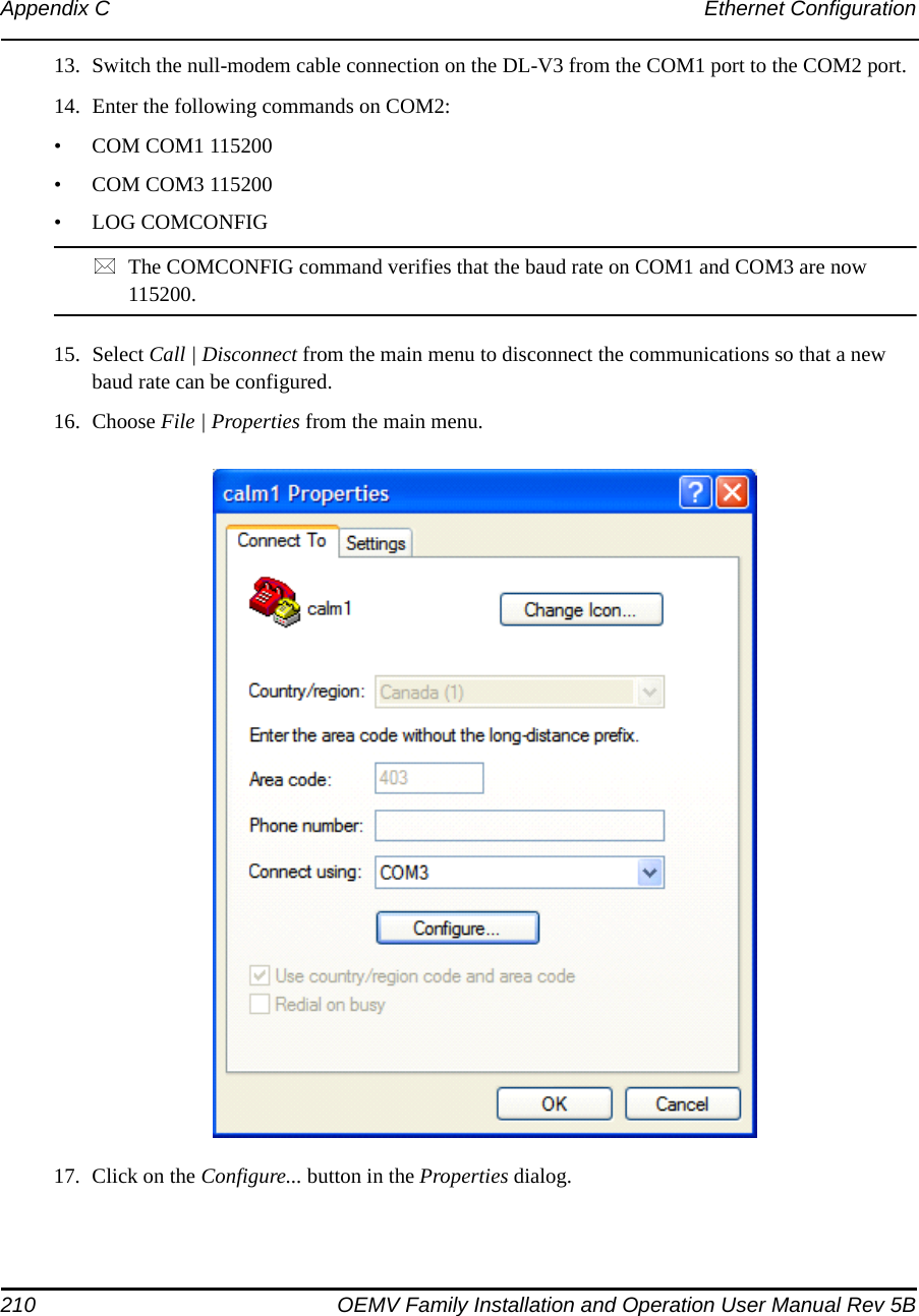
![208 OEMV Family Installation and Operation User Manual Rev 5BAppendix C Ethernet Configuration8. Ensure that the Echo typed characters locally check box is checked this time.9. Click on the OK buttons until you return to the main HyperTerminal window.10. Enter the following command in the main window (that is in Command Mode)• enableFigure 81 shows an example of the Ethernet communication in command mode. The xyz and enable commands can be seen near the top. The other commands that follow are shown in the next section. Refer back to Figure 81, as you follow the next section’s instructions, to see if you get the expected results. If not return to step C.4.3.3 and try again. Figure 81: Command Mode Example char *acCmds[] = { // expect: "xyz", // > "enable\r", // (enable)# "configure\r", // (config)# "if 1\r", // (if-1)# "ip address ", // (if-1)# "no dhcp\r", // (if-1)# "speed auto\r", // (if-1)# "write\r", // (if-1)# "exit\r", // (config)# "exit\r", // (enable)# "line 1\r", // (line-1)# "databits 8\r", // (line-1)# "flowcontrol hardware\r", // (line-1)# "speed 115200\r", // (line-1)# "write\r", // (line-1)# "exit\r", // (enable)# "reload\r", // Are you sure (yes/no)? "yes\r", // Rebooting... 0 };](https://usermanual.wiki/Novatel/01017829.User-Manual-part-2/User-Guide-777995-Page-100.png)