Novatel 01018300 GPS Receiver User Manual OM 20000123SmartAG
Novatel Inc GPS Receiver OM 20000123SmartAG
UserManual.wiki
>
Novatel
>
01018300 User Manual
User Manual
Navigation menu
Upload a User Manual
Namespaces
Wiki Guide
HTML
PDF
Info
Views
User Manual
Discussion / Help
Navigation


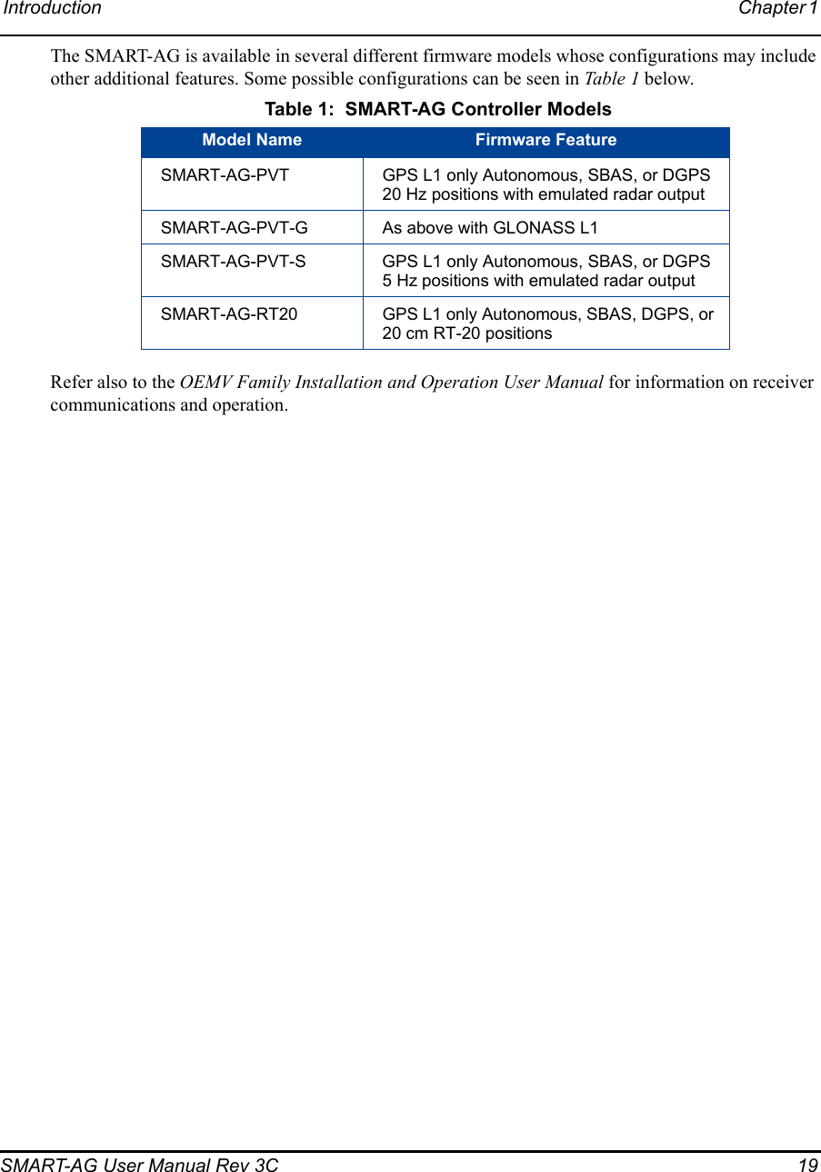
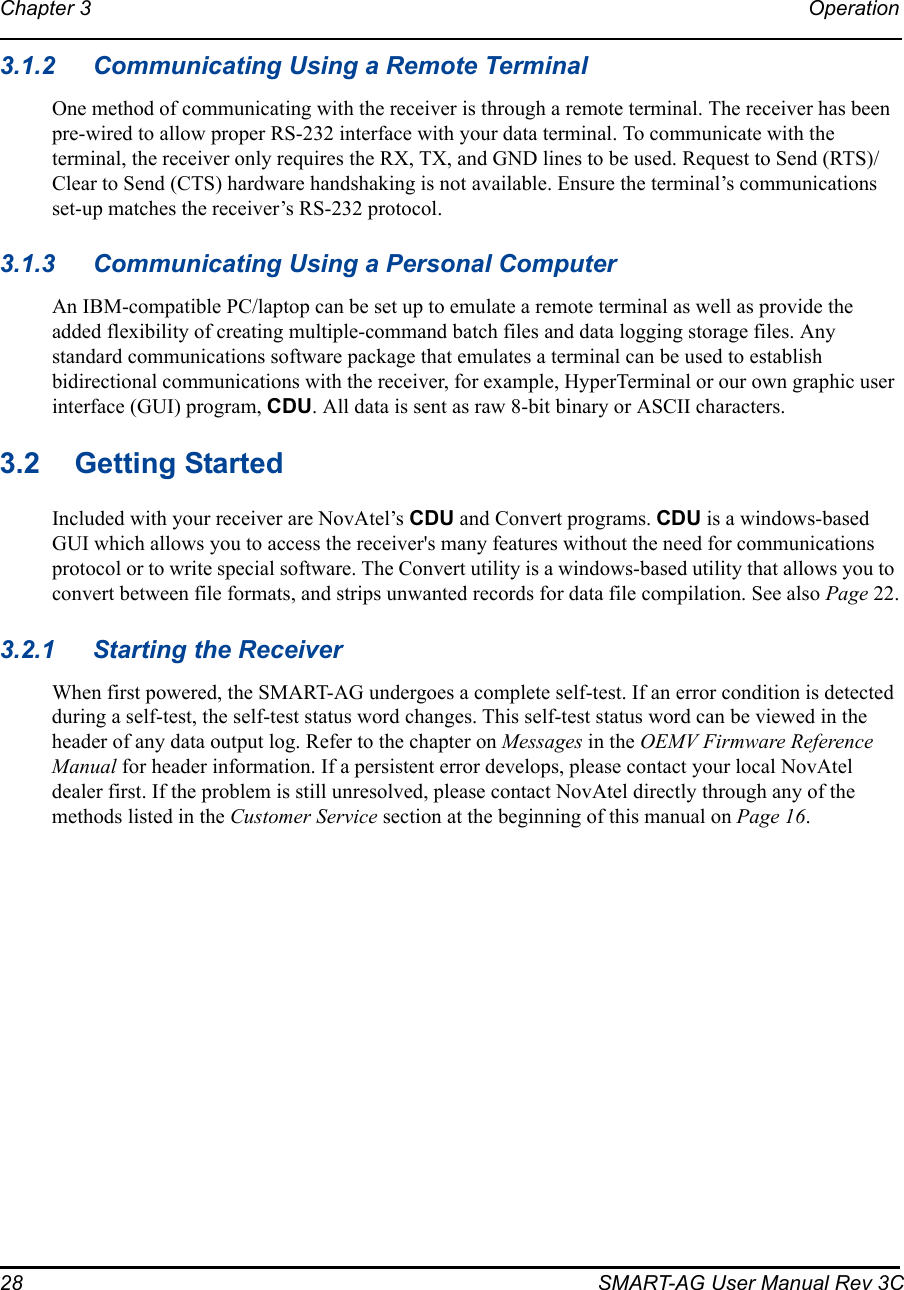
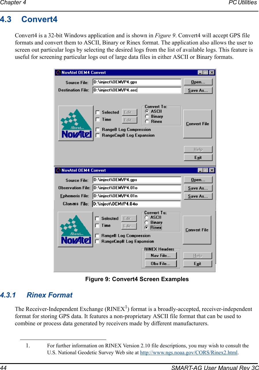
![ForewordSMART-AG User Manual Rev 3C 17ConventionsConventions used in this manual are the following:This is a notebox that contains important information.• The letter H in the Offset columns of the commands and logs tables represents the header length for that command or log. Refer to the OEMV Family Firmware Reference Manual for ASCII and binary header details.• The number following 0x is a hexadecimal number.• Command descriptions’ brackets, [ ], represent the optionality of parameters.• In tables where values are missing they are assumed to be reserved for future use.• Status words are output as hexadecimal numbers and must be converted to binary format (and in some cases then also to decimal). For an example of this type of conversion, please refer to the RANGE log in the OEMV Family Firmware Reference Manual.Conversions and their binary or decimal results are always read from right to left. For a complete list of hexadecimal, binary and decimal equivalents, please refer to the Unit Conversion section of the GNSS Reference Book available on our Web site at http://www.novatel.com/support/docupdates.htm.See also Section B.1, Syntax Conventions on Page 64 for more syntax when entering commands.](https://usermanual.wiki/Novatel/01018300/User-Guide-1213806-Page-17.png)
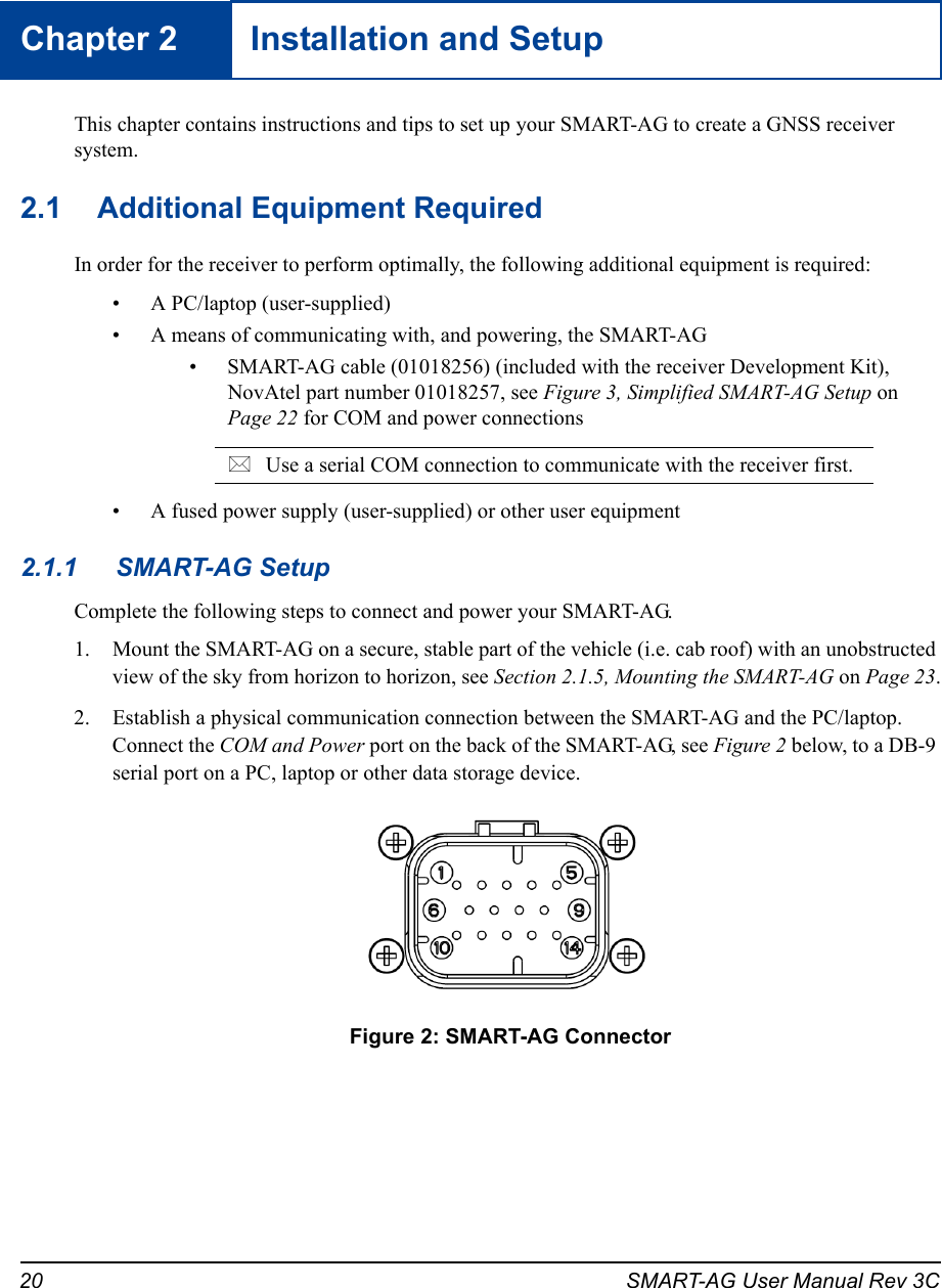

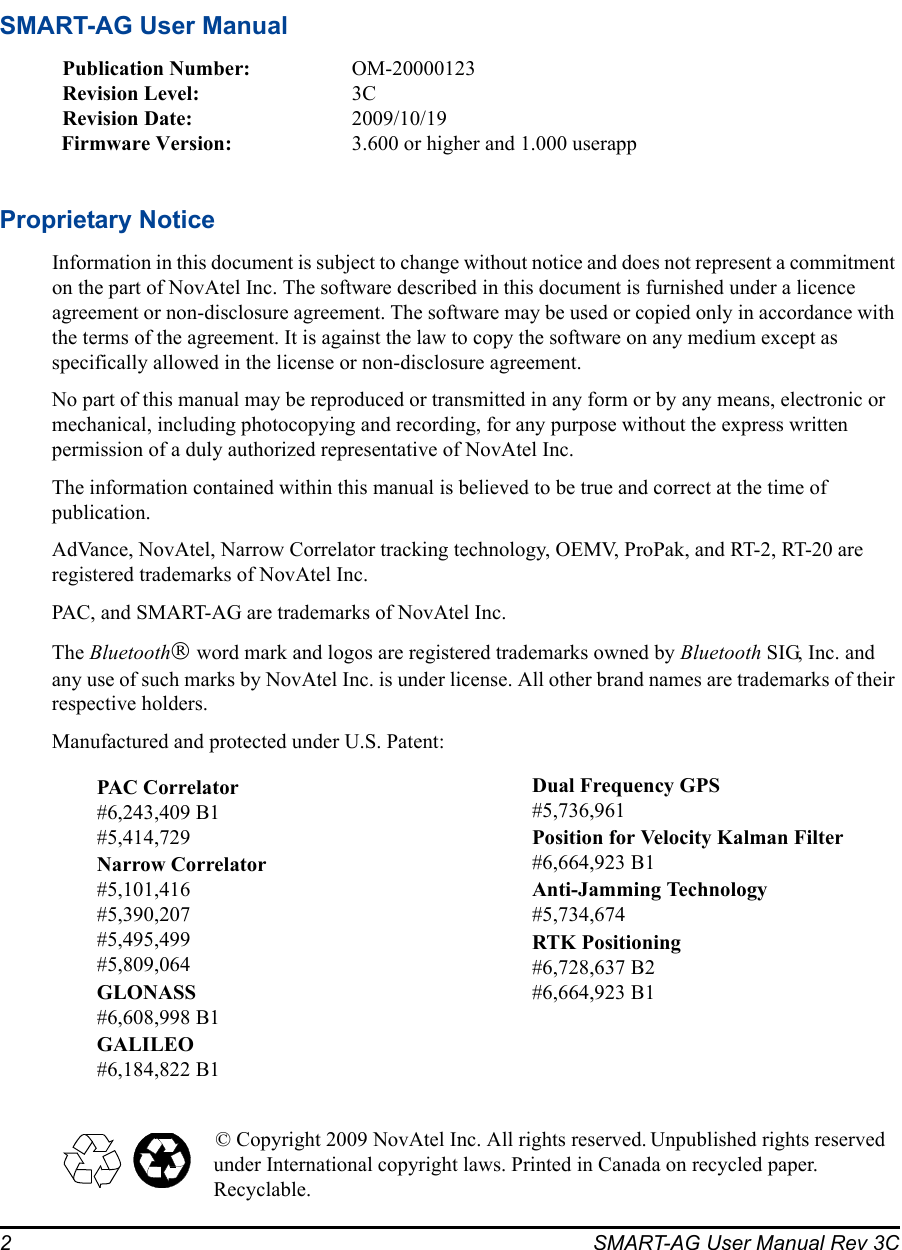
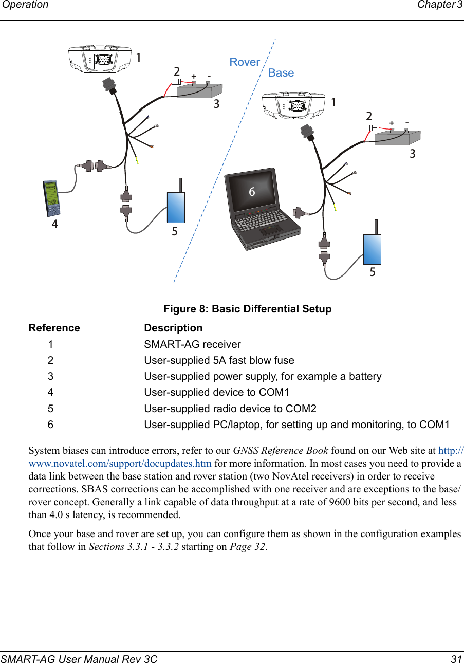
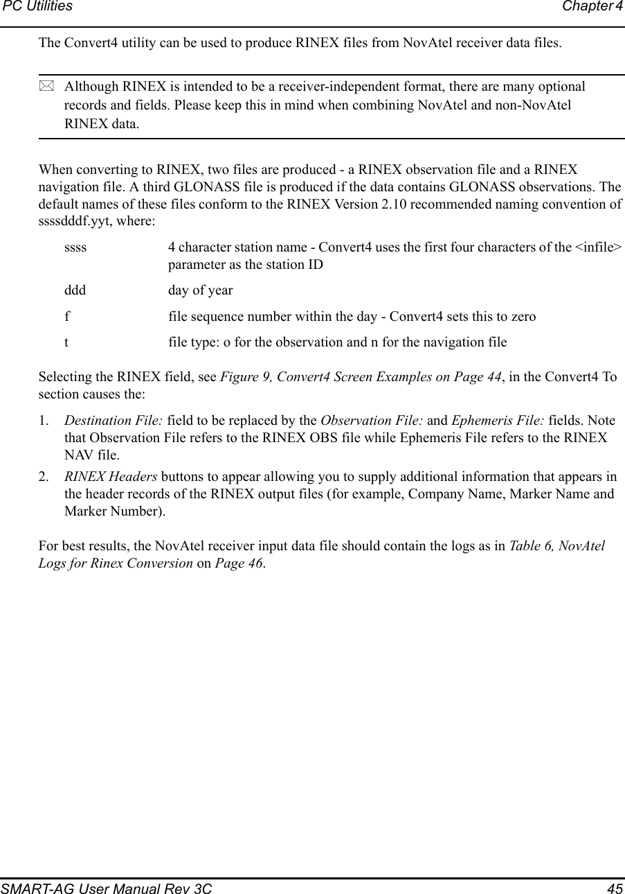
![Operation Chapter 3 SMART-AG User Manual Rev 3C 293.2.2 Communicating with the Receiver Using CDULaunch the CDU program and select Device | Open from its main menu. The Open Configuration window appears. Figure 7, below, shows an Open Configuration window with two possible configurations already set up. Your configurations may be different or you may have none at all, in which case, the Open Configuration window is empty. Figure 7: Open Configuration WindowRefer to CDU’s help file by selecting the Help | Contents menu. Ensure you can see the Console and ASCII Messages windows by selecting them from the View menu.When the receiver is first turned on, no data is transmitted from the COM ports except for the port prompt. The console window displays a port name:[COM1] if connected to COM1 port,or[COM2] if connected to COM2 port,Any of the above prompts indicate that the receiver is ready and waiting for command input. 1. You may also have to wait for output from receiver self tests. For example, on start-up, the OEMV family receiver is set to log the RXSTATUSEVENTA log ONNEW on all ports. Refer to the OEMV Family Firmware Reference Manual for more details.2. If you find that CDU is unable to locate your OEMV family receiver, it may be that you have previously used the SAVECONFIG command. In this case, try using a different COM port to communicate to the receiver. Once communication has been established, issue the command FRESET STANDARD. You should now be able to use your original communication port again.](https://usermanual.wiki/Novatel/01018300/User-Guide-1213806-Page-29.png)
![30 SMART-AG User Manual Rev 3CChapter 3 Operation Commands are typed at the interfacing computing device’s keypad or keyboard, and executed after issuing a carriage return command which is usually the same as pressing the <Enter> key.An example of a response to an input command is the FIX POSITION command. It can be as:[COM2] fix position 51.11635 -114.0383 1048.2 [carriage return]<OKwhere [COM2] is the port prompt, followed by the command you enter from your keypad or keyboard and [carriage return] indicates that you should press the <Enter> key.The example above illustrates the command input to the base receiver’s COM2 port, which sets the position of the base station receiver for differential operation. Confirmation that the command was actually accepted is the appearance of <OK.If a command is entered incorrectly, the receiver responds with:<INVALID MESSAGE ID (or a more detailed message)WARNING!: Ensure the Control Panel’s Power Settings on your PC/laptop are not set to go into Hibernate or Standby modes. Data will be lost if one of these modes occurs during a logging session.3.3 Transmitting and Receiving CorrectionsRTK or DGPS corrections can be transmitted from a base station to a rover station to improve position accuracy. The base station is the GNSS receiver, which is acting as the stationary reference. It has a known position and transmits correction messages to the rover station. The rover station is the GNSS receiver which does not know its exact position and can be sent correction messages from a base station to calculate differential GNSS positions. The SMART-AG can be used as a base receiver to transmit RTK or DGPS corrections or a rover to receive the same corrections. An example of a differential setup is given in Figure 8 on Page 31.](https://usermanual.wiki/Novatel/01018300/User-Guide-1213806-Page-30.png)
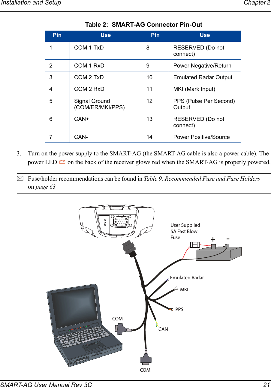
![32 SMART-AG User Manual Rev 3CChapter 3 Operation 3.3.1 Base Station ConfigurationAt the base station, enter the following commands:interfacemode port rx_type tx_type [responses]fix position latitude longitude heightlog port message [trigger [period]]Examples of these commands include the following:RTCA interfacemode com2 none rtca offfix position 51.11358042 -114.04358013 1059.4105log com2 rtcaobs ontime 1log com2 rtcaref ontime 10log com2 rtca1 ontime 5 (optional for rtk)log com2 rtcaephem ontime 10 1 (optional)RTCM interfacemode com2 none rtcm offfix position 51.11358042 -114.04358013 1059.4105log com2 rtcm3 ontime 10 (required for RTK)log com2 rtcm22 ontime 10 1 (optional)log com2 rtcm1819 ontime 1log com2 rtcm1 ontime 5RTCMV3 interfacemode com2 none rtcmv3 offfix position 51.11358042 -114.04358013 1059.4105log com2 rtcm1006 ontime 10log com2 rtcm1003 ontime 1CMR+ interfacemode com2 none cmr offfix position 51.11358042 -114.04358013 1059.4105log com2 cmrobs ontime 1log com2 cmrplus ontime 1 (important to use ontime 1 with cmrplus)CMR interfacemode com2 none cmr offfix position 51.11358042 -114.04358013 1059.4105log com2 cmrobs ontime 1log com2 cmrref ontime 10log com2 cmrdesc ontime 10 1](https://usermanual.wiki/Novatel/01018300/User-Guide-1213806-Page-32.png)
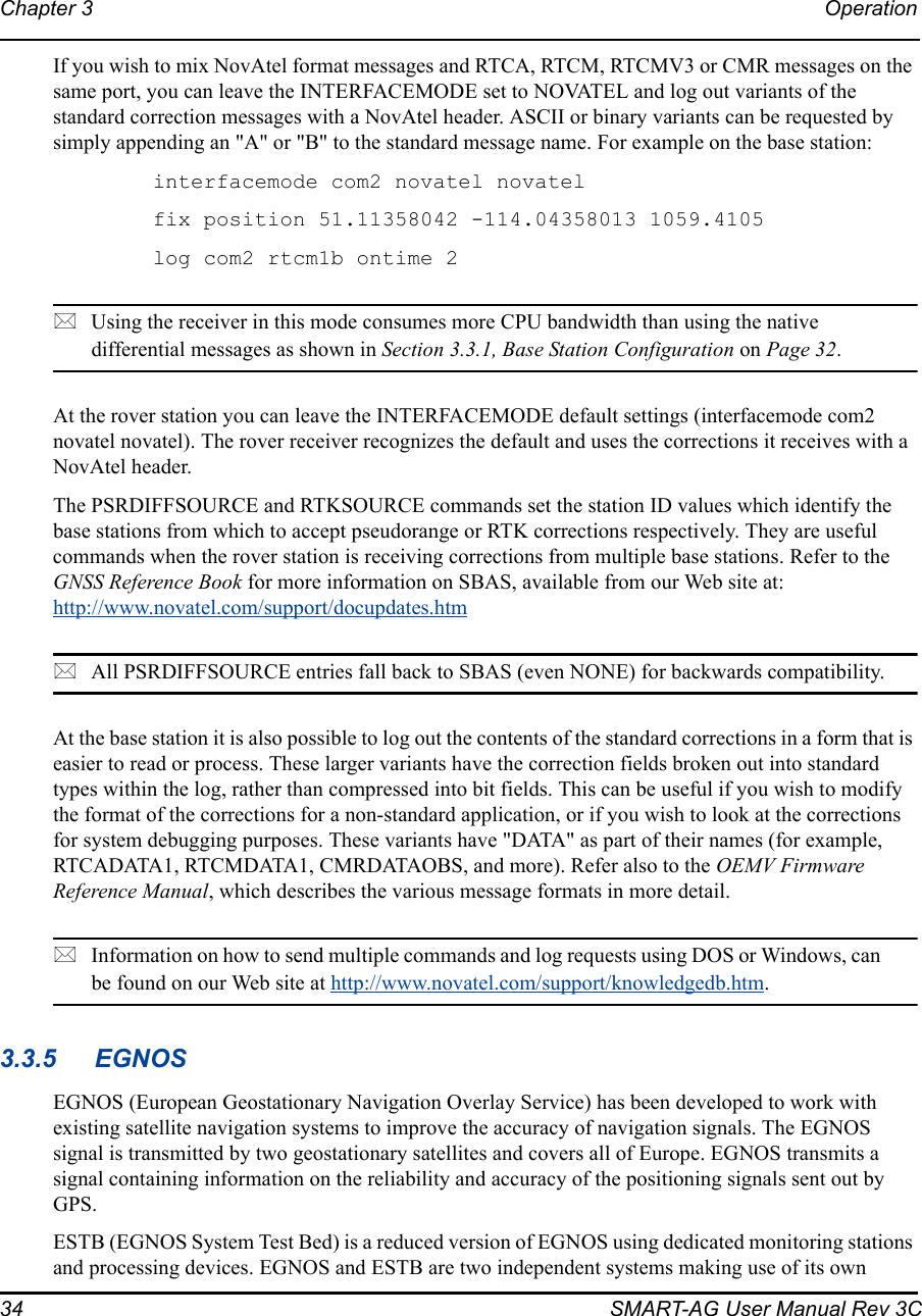
![Operation Chapter 3 SMART-AG User Manual Rev 3C 333.3.2 Rover Station ConfigurationAt the rover station, enter:interfacemode port rx_type tx_type [responses]For example:RTCA interfacemode com2 rtca none offRTCM interfacemode com2 rtcm none offRTCMV3 interfacemode com2 rtcmv3 none offCMR+ interfacemode com2 cmr none offCMR interfacemode com2 cmr none off (same as CMR+)3.3.3 GPS + GLONASS Base and Rover ConfigurationThis section shows you how to set up your base and rover OEMV GPS + GLONASS-enabled receivers for GPS + GLONASS RTK operation: Base Station: fix position lat lon hgt (enter your own lat, lon, and hgt values) com com2 9600 N 8 1 N off interfacemode com2 none rtca off log com2 rtcaref ontime 10 log com2 rtcaobs2 ontime 1 log com2 rtca1 ontime 5 (optional, enable code-DGPS coverage)saveconfig (optional, save configuration to non-volatile memory)Rover Station: com com2 9600 N 8 1 N off interfacemode com2 rtca none off log com1 bestposa ontime 1 (optional, view position information) saveconfig (optional, save configuration to non-volatile memory)3.3.4 Configuration NotesFor compatibility with other GNSS receivers, and to minimize message size, it is recommended that you use the standard form of RTCA, RTCM, RTCMV3 or CMR corrections as shown in the base and rover examples above. This requires using the INTERFACEMODE command to dedicate one direction of a serial port to only that message type. When the INTERFACEMODE command is used to change the mode from the default, NOVATEL, you can no longer use NovAtel format messages.](https://usermanual.wiki/Novatel/01018300/User-Guide-1213806-Page-33.png)
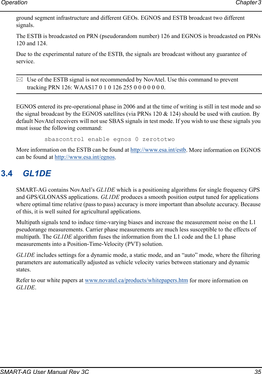
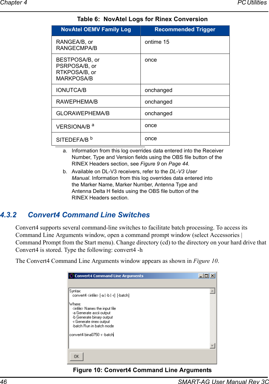
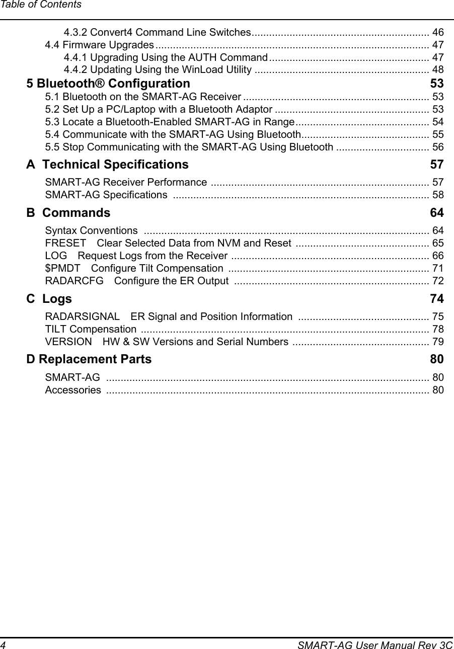
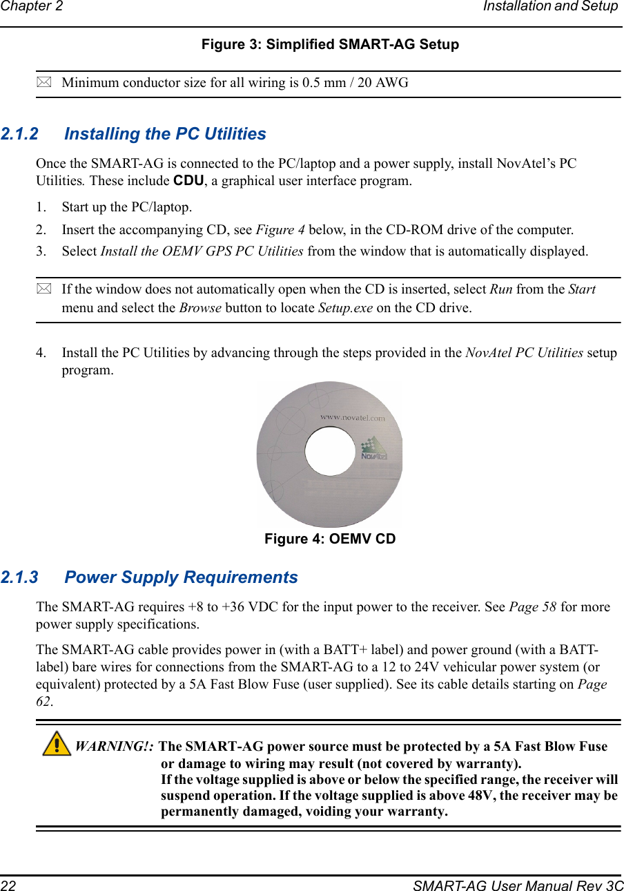
![PC Utilities Chapter 4 SMART-AG User Manual Rev 3C 49You will need at least 1 MB of available space on your hard drive. For convenience, you may wish to copy this file to a GPS sub-directory (for example, C:\GPS\LOADER).The file is available in a compressed format with password protection; Customer Service will provide you with the required password. After copying the file to your computer, it must be decompressed. The syntax for decompression is as follows:Syntax:[filename] [password]where filename is the name of the compressed file (but not including the .EXE extension) and password is the password required to allow decompressionExample:oem1001 12345678A windows-based dialog box is provided for password entry.The self-extracting archive will then generate the following files:WinLoad.exe WinLoad utility programHowTo.txt Instructions on how to use the WinLoad utilityWhatsNew.txt Information on the changes made in the firmware since the last revisionXXXX.hex Firmware version upgrade file, where XXXX = program version level (for example, 1001.hex)Using the WinLoad UtilityWinLoad is a windows based program used to download firmware to OEMV family cards. The main screen is shown in Figure 11 on Page 49. Figure 11: Main Screen of WinLoad](https://usermanual.wiki/Novatel/01018300/User-Guide-1213806-Page-49.png)

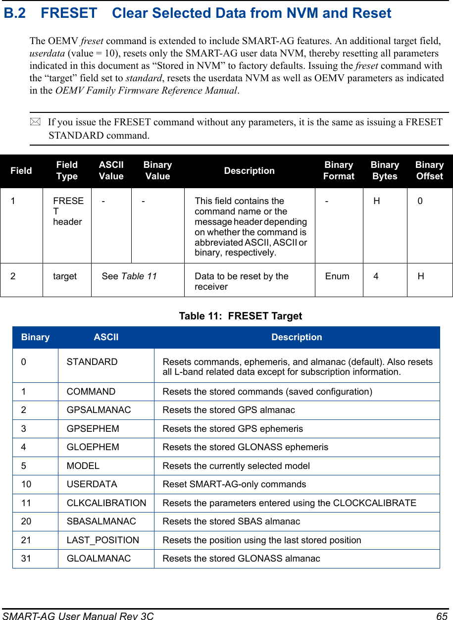
![SMART-AG User Manual Rev 3C 64Appendix B CommandsThe SMART-AG firmware implements the commands in Tab le 1 0, in addition to the OEMV family command set. The LOG command is available to all OEMV receivers but is an essential command to do any logging. It is included in this appendix for your convenience. Table 10: SMART-AG Commands in Alphabetical OrderThe arguments for each of these commands are described in the following sections.For a complete listing and description of the other commands that the SMART-AG, an OEMV-1G-based receiver, is capable of processing, refer to the OEMV Family Firmware Reference Manual.B.1 SYNTAX CONVENTIONSThe following rules apply when entering commands, at the command prompt, from a keyboard.1. Courier font is used to illustrate program output or user input.2. References to other commands, logs or any of their fields are shown in italics.3. The commands are not case sensitive. For example, you could type either RESET or reset.4. Except where noted, either a space or a comma can separate commands and their required entries. For example, you could type either fix position 51.11358042 -114.04358013 1059.4105 or fix position 51.11358042, -114.04358013, 1059.4105.5. At the end of a command, a carriage return is required. For example, press <Enter> or <Return> on your keyboard.6. Responses are provided to indicate whether or not an entered command was accepted. The format of the response depends on the format of the command. Refer to the OEMV Family Firmware Reference Manual for more information.7. Optional parameters are indicated by square brackets ( [ ] ). For commands that contain optional parameters, the value used if the optional parameter is not specified is given in the syntax table for the command.8. Data format definitions, as specified in the “Format” field, are detailed in the OEMV Family Firmware Reference Manual. Note that all binary data is little-endian byte-ordered.ASCII Command Message ID Descriptionfreset 20 Factory reset (Existing OEMV Command extended to SMART-AG)log 1 Request logs from the receiver (Existing OEMV Command extended to SMART-AG)radarcfg 8192 Configure the ER signal output (New SMART-AG command)reset 18 Perform a hardware reset (Existing OEMV Command extended to SMART-AG)](https://usermanual.wiki/Novatel/01018300/User-Guide-1213806-Page-64.png)
![66 SMART-AG User Manual Rev 3CB.3 LOG Request Logs from the ReceiverMany different types of data can be logged using several different methods of triggering the logevents. Every log element can be directed to any combination of the three COM ports and three USBports. The ONTIME trigger option requires the addition of the period parameter. See the OEMVFirmware Reference Manual and the SMART-AG Firmware Reference Manual for further informationand a complete list of data log structures. The LOG command tables in this section show the ASCIIcommand format.The optional parameter [hold] prevents a log from being removed when the UNLOGALL command,with its defaults, is issued. To remove a log which was invoked using the [hold] parameter requires thespecific use of the UNLOG command. To remove all logs that have the [hold] parameter, use theUNLOGALL command with the held field set to 1.The [port] parameter is optional. If [port] is not specified, [port] is defaulted to the port that the com-mand was received on.* 1. The OEMV family of receivers can handle 30 logs at a time. If you attempt to log more than 30 logs at a time, the receiver responds with an Insufficient Resources error. Each COM port (serial and USB) already has RXSTATUSEVENT log associated with it. This means that with 3 serial ports and 3 USB ports, 6 logs are already accounted for. See the example on the next page. 2. Maximum flexibility for logging data is provided to the user by these logs. The user is cautioned, however, to recognize that each log requested requires additional CPU time and memory buffer space. Too many logs may result in lost data and degraded CPU performance. Receiver overload can be monitored using the idle-time field and buffer overload bits of the Receiver Status in any log header.3. Polled log types do not allow fractional offsets or ONTIME rates faster than 1Hz.4. Use the ONNEW trigger with the MARKTIME, MARK2TIME, MARKPOS or MARK2POS logs.](https://usermanual.wiki/Novatel/01018300/User-Guide-1213806-Page-66.png)
![SMART-AG User Manual Rev 3C 675. Only the MARKPOS, MARK2POS, MARKTIME or MARK2TIME logs, and ‘polled’ log types are generated ‘on the fly’ at the exact time of the mark. Synchronous and asynchronous logs output the most recently available data.6. If you do use the ONTIME trigger with asynchronous logs, the time stamp in the log does not necessarily represent the time the data was generated, but rather the time when the log is being transmitted.Abbreviated ASCII Syntax: Message ID: 1LOG [port] message [trigger [period [offset [hold]]]]Factory Default:log com1 rxstatuseventa onnew 0 0 holdlog com2 rxstatuseventa onnew 0 0 holdlog com3 rxstatuseventa onnew 0 0 holdlog aux rxstatuseventa onnew 0 0 holdlog usb1 rxstatuseventa onnew 0 0 holdlog usb2 rxstatuseventa onnew 0 0 holdlog usb3 rxstatuseventa onnew 0 0 holdAbbreviated ASCII Example 1:log com1 bestpos ontime 7 0.5 holdThe above example shows BESTPOS logging to COM port 1 at 7 second intervals and offset by 0.5 seconds (output at 0.5, 7.5, 14.5 seconds and so on). The [hold] parameter is set so that logging is not disrupted by the UNLOGALL command.To send a log only one time, the trigger option can be ignored. Abbreviated ASCII Example 2:log com1 bestpos once 0.000000 0.000000 noholdRefer to the Command Formats section of the OEMV Firmware Reference Manual for additional examples.*1.In CDU there are two ways to initiate data logging to the receiver's serial ports. You can either enter the LOG command in the Console window, or use the interface provided in the Logging Control window. Ensure the Power Settings on your PC are not set to go into Hibernate or Standby modes. Data is lost if one of these modes occurs during a logging session.2. Only the ASCII/Abbreviated ASCII log table is included in this manual. Please refer to the LOG command in the OEMV Family Firmware Reference Manual for binary log details.](https://usermanual.wiki/Novatel/01018300/User-Guide-1213806-Page-67.png)
![68 SMART-AG User Manual Rev 3CFieldFieldNameASCIIValue Description Field Type1LOG (ASCII) header- This field contains the command name or the message header depending on whether the command is abbreviated ASCII or ASCII respectively.-2 port See Table 12, Detailed Serial Port Identifiers on Page 69Output port(default = THISPORT)Enum3 message Any valid message name, with an optional A or B suffix.Message name of log to output Char [ ]4 trigger ONNEW Output when the message is updated (not necessarily changed)EnumONCHANGED Output when the message is changedONTIME Output on a time intervalONNEXT Output only the next messageONCE Output only the current message. (default)ONMARK Output when a pulse is detected on the mark 1 input, MK1I 5 period Any positive double value larger than the receiver’s minimum raw measurement periodLog period (for ONTIME trigger) in seconds(default = 0)Double6 offset Any positive double value smaller than the period.Offset for period (ONTIME trigger) in seconds. If you wished to log data at 1 second after every minute you would set the period to 60 and the offset to 1 (default = 0)Double7 hold NOHOLD Allow log to be removed by the UNLOGALL command (default)EnumHOLD Prevent log from being removed by the UNLOGALL command](https://usermanual.wiki/Novatel/01018300/User-Guide-1213806-Page-68.png)
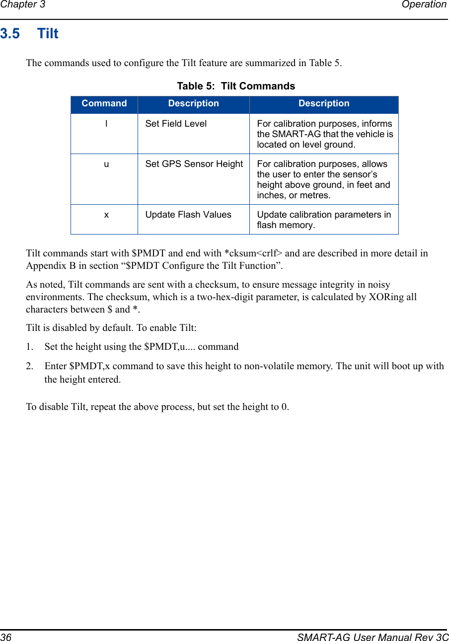
![SMART-AG User Manual Rev 3C 71B.4 $PMDT Configure Tilt CompensationUse this command to configure the Tilt Compensation function.Syntax$PMDT,[command],[parameters]*cksumHost Description Command Format Tilt Sensor ResponselSet Field Level $PMDT,l,*cksum crlfExample:$PMDT,l*4D)Response to the “l” command:$PMDT,<,Level state set crlfExample:$PMDT,<,Level state setua ba. If all fields in the u command are zero or null, the current height is transmitted without change (with the format shown above).b. If an invalid entry is received (>500 inches), the response is:$PMDT,<Max legal height exceeded: nnnnn and will be ignored clrfFor example, if you enter 42 ft 6 in, you will get the following response:$PMDT,<,Max legal height exceeded: 00510 and will be ignored$PMDT,<,GPS sensor height (inches): 00150Set GPS Sensor HeightTo set the GPS sensor height in feet and inches:$PMDT,u,,ff,ii,*cksum crlfExample: To set the GPS sensor height to 12 ft 6 in, the command is:$PMDT,u,,12,6*4D)Note: Feet and inches are entered as integers, You can enter feet and inches, but not feet, inches and metres.Response to the “u” command:$PMDT,<,GPS sensor height (inches):nnnnn crlfwhere nnnnn is a five digit integer, sensor height in inches.In this example, the Tilt Sensor response is:$PMDT,<,GPS sensor height (inches): 00150To set the GPS sensor height in metres:$PMDT,u,,,,mmm.mmm *cksum crlfExample: To set the GPS sensor height to 3.5 metres, the command is:$PMDT,u,,,,3.5*5CRepsonse to the ”u” command:$PMDT,<,GPS sensor height (inches):nnnnn crlfwhere nnnnn is a five digit integer, sensor height in inches.In this example, the Tilt Sensor response is:$PMDT,<,GPS sensor height (inches): 00137xUpdate Flash ValuesTo update flash values (needs to follow any parameter update that is not done each time you power up):$PMDT,x,*cksum crlfExample:$PMDT,c,*59Response to thje “x” command:$PMDT,<,Flash updated crlfExample:$PMDT,<,Flash updated](https://usermanual.wiki/Novatel/01018300/User-Guide-1213806-Page-71.png)
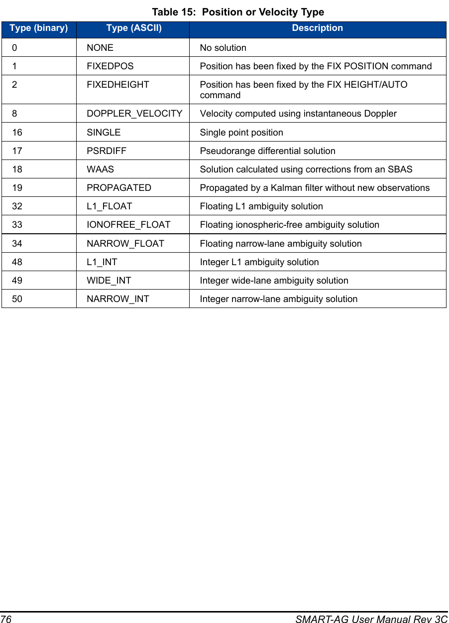
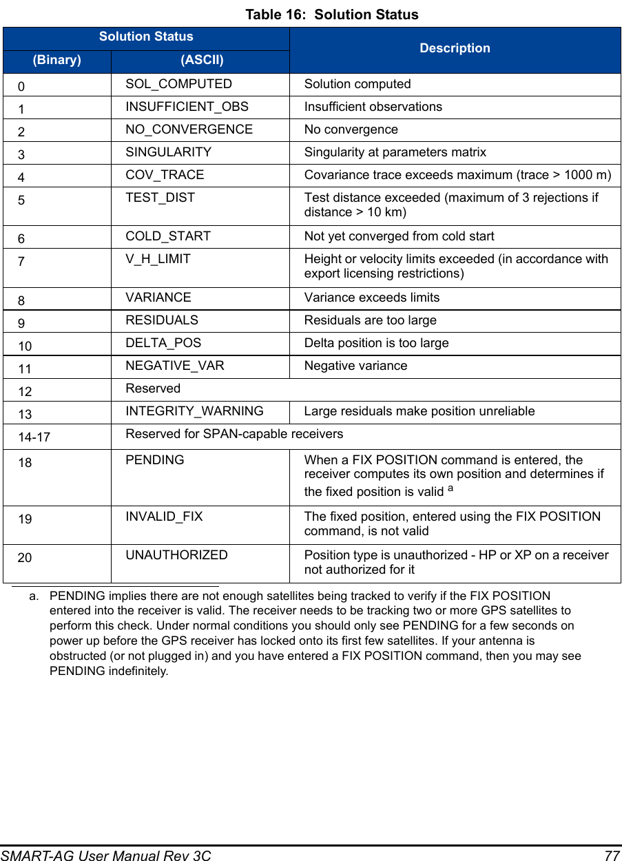
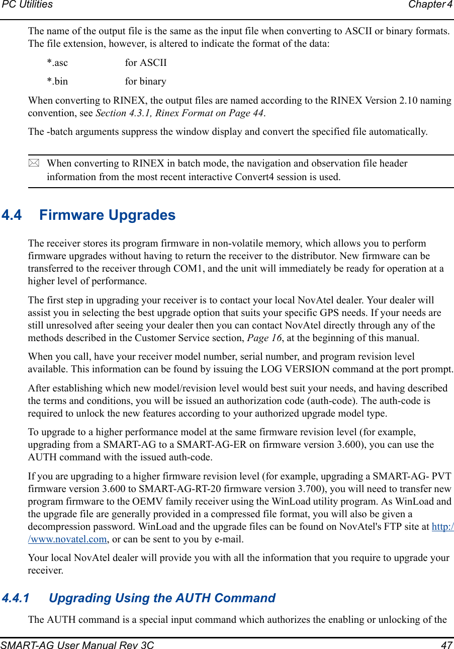
![SMART-AG User Manual Rev 3C 75C.1 RADARSIGNAL ER Signal and Position InformationThis log contains position and Emulated Radar (ER) signal information.Message ID: 8193Log Type: AsynchRecommended Input:log radarsignala onchangedASCII Example 1 (stationary SMART-AG):#RADARSIGNALA,COM1,0,61.5,FINESTEERING,1501,248381.628,00000000,8a1c,3723;SOL_COMPUTED,WAAS,0.0139,0.00,0.00*f0d580caASCII Example 2 (moving SMART-AG):#RADARSIGNALA,COM1,0,42.5,FINESTEERING,1428,206179.600,00000000,baa8,3349;SOL_COMPUTED,WAAS,0.3315,2,0.3152,473.97,29.62*c1479c20Field # Field type Data Description Format BinaryBytesBinaryOffset1RADAR-SIGNAL headerLog header H 02sol status Solution status, see Table 16, Solution Status on Page 77Enum 4 H3vel type Velocity type, see Table 15, Position or Velocity Type on Page 76Enum 4H+44speed Speed over ground (m/s) Double 8H+84varf freq External VARF output frequency (Hz) Double 8H+165radar freq Radar signal frequency (Hz) as output by the Emulated Radar Out signal. See SMART-AG Development Kit Cable starting on Page 60.Double 8H+246 xxxx 32-bit CRC (ASCII and Binary only) Hex 4H+327[CR][LF] Sentence terminator (ASCII only) - - -](https://usermanual.wiki/Novatel/01018300/User-Guide-1213806-Page-75.png)