Novra Technologies A750100 Communications Receiver User Manual Manual
Novra Technologies Inc. Communications Receiver Manual
Manual
Confidential and Proprietary Version DRAFT 2004APR29 1 of 11
Novra
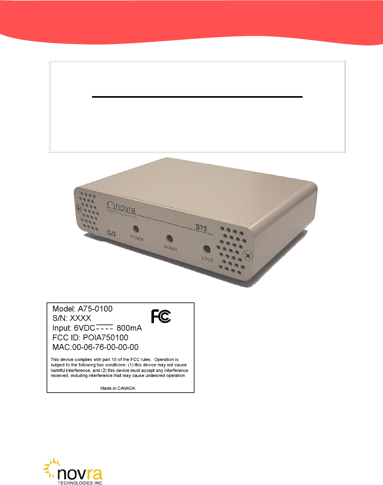
A
75 Receiver
Novra A75 Receiver Instructions
Subject to change without notification
CAUTION: Any changes or modifications not expressly approved by the manufacturer could
void the user's authority to operate this equipment.
These Files have been optimized for printing.

Confidential and Proprietary Version DRAFT 2004APR29 2 of 11
Novra
A
75 Receiver
Novra A75 Receiver Instructions
Subject to change without notification
Document version: DRAFT 2004APR29
________________________________
Important- Please read this entire manual before installing or operating this product.
________________________________
Disclaimer
While reasonable effort has been made in the preparation of this document to assure its accuracy, Novra
Technologies Inc. assumes no responsibility for errors or omissions that may appear in this manual. Novra
reserves the right to change the contents of this manual at any time without notice.
Copyright
© 2004 Novra Technologies Inc. All rights reserved.
Information in this manual is subject to change without notice. No part of this manual may be reproduced or
transmitted in any form, by photocopy, microfilm, xerography, or any other means, or incorporated into any
information retrieval system, electronic or mechanical, for any purpose, without the express written permission
of Novra Technologies Inc.
For additional information or details on Novra's product offerings, please contact us at:
North American Headquarters 1100-330 St. Mary Avenue, Winnipeg, MB Canada R3C-3Z5
t. 204.989.4724 f. 204.989.4640 e. info@novra.com w. www.novra.com
Confidential and Proprietary Version DRAFT 2004APR29 3 of 11
Novra
A
75 Receiver
INDEX Page
1.0 MINIMUM SYSTEM REQUIREMENTS 3
2.0 INTRODUCTION 4
2.1 Principle Of Operations 4
3.0 INSTALLATION 5
4.0 MANAGEMENT CONSOLE SYSTEM CONFIGURATIONS 6
4.1 Configuring the A75 Data Receiver 6
6.0 A75 RECEIVER SPECIFICATIONS 8
APPENDIX
Miscellaneous Terms and Definitions 9
1.0 Minimum System Requirements
Your computer must have at least the following:
• Processor: Pentium 566 MHz
• RAM: 32 MB
• Free disk space: 40 MB
• Video: card and driver that support 256 or more colours
• CD drive (required for software installation only)
• Ethernet network interface card (NIC): 100 Mbps (100 BaseT)
NOTE: - The receiver may work with system parameters below those specified but
performance ma
y
be lackin
g
.
NOTE: - Performance will be dependant on other applications that your computer is
running.

Confidential and Proprietary Version DRAFT 2004APR29 4 of 11
Novra
A
75 Receiver
2.0 INTRODUCTION
2.1 Principles of Operation
Somewhere in the world is a location that transmits your signal, along with many others, to your
location and others. Your A75 sifts through all the signals for your signal, a DVB data stream. The
A75 then de-encapsulates the IP information from the DVB stream and forwards it onto its final
destination via a 100 Base-T Ethernet link.
The A75 also transmits status packets to your computer where the A75 Management Console is
located.
The A75 Management Console is used to configure addresses, specify tuning parameters and select
DVB information streams (PIDS). Once configured, the A75 will retain its settings and continue to
forward data transmitted to you by your service provider even after restarting the A75 or your
computer.
The A75 Receiver is meant to run in the background. In most cases, once the options have been set,
you will have no need to change them.

Confidential and Proprietary Version DRAFT 2004APR29 5 of 11
Novra
A
75 Receiver
3.0 INSTALLATION
8-VSB
Novra
A75
100BaseT
IP over
Ethernet
Windows
Macintosh
xnix
DTV
Multiplex
Figure 1: A75 Hardware Connections
1) Connect the S75 Receiver to the RG6 coax cable that is attached your outdoor antenna.
CAUTION: There are grounding requirements and other safety considerations associated with
your outdoor antenna. Be sure to follow all local electrical standards and codes when installing
and using an antenna.

Confidential and Proprietary Version DRAFT 2004APR29 6 of 11
Novra
A
75 Receiver
2) Connect the 6 VDC adapter to the A75 .
3) Connect the Crossover Ethernet cable (Null-modem) between your computer's 100 BaseT NIC
card and the A75. (Or the A75 can be connected to the computer via a Hub with regular Ethernet
cables.)
4) On your computer, create a file folder called "A75." The file folder can be under "Program Files"
or in any other location.
Note: The system will create additional files containing various configuration aspects as they are
created. The system will locate these additional files in the same directory as the A75
Management Console.exe program.
5) Copy the file A75 Management Console.exe from the CD ROM to the "A75" file folder.
6) Shortcuts can be created if desired through the normal Windows procedures.
7) Open (run) the A75 Management Console.exe and proceed to section 4.0.
Confidential and Proprietary Version DRAFT 2004APR29 7 of 11
Novra
A
75 Receiver
4.0 MANAGEMENT CONSOLE SYSTEM CONFIGURATIONS
4.1 Configuring the A75 Data Receiver
The data receiver configuration is very straightforward and can be shown in four basic steps:
1. Open (run) the A75 Management Console application
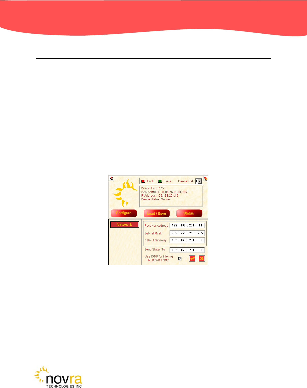
2. Configure the receiver IP addresses.
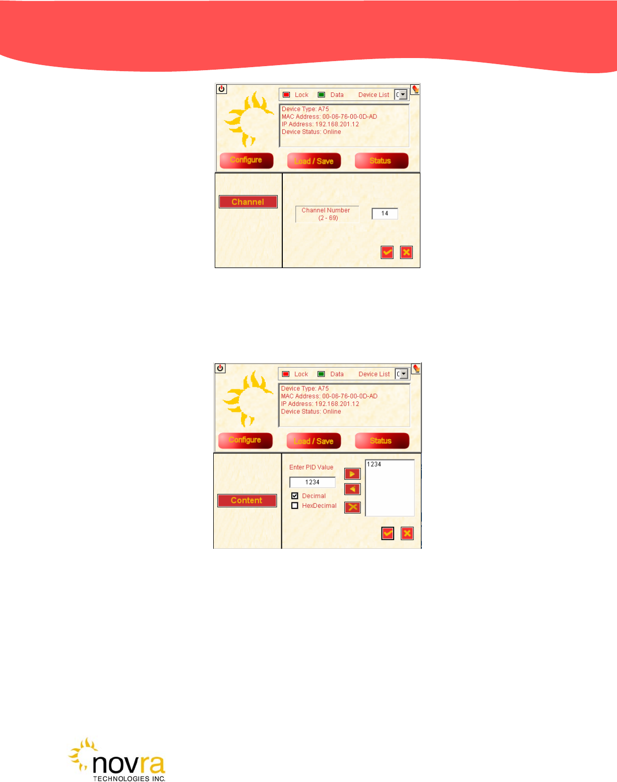
3. Set the receive channel.
4. Set the PID.
Each of these three basic steps is presented below.
Step 2: In figure 2, the A75 receiver IP addresses are configured according to the LAN at the receive site.
Figure 2: Receiver IP Addresses
Step 3: In figure 3, the receiver is tuned to channel 14, to match the broadcast modulator.
Confidential and Proprietary Version DRAFT 2004APR29 8 of 11
Novra
A
75 Receiver
Figure 3: Set the Channel
Step 4: In figure 4, the PID is selected to match the data PID defined in the transmitting end.
Figure 4: Set the PID

Confidential and Proprietary Version DRAFT 2004APR29 9 of 11
Novra
A
75 Receiver
5.0 A75 RECEIVER SPECIFICATIONS
Receiver
o Receiving Frequency: 54 to 806 MHz
o ATSC Channels: 2 to 69
o Input Signal Level: -80 dBm to 0 dBm
o Channel Bandwidth: 6 MHz
o Phase Noise: -89 dBc/Hz @ 10kHz
o Demodulation: 8-VSB
o Channel Bit Rate (raw): 19.38 Mbps
o FEC: Reed-Solomon and Viterbi
o Noise Figure: 8 dB
o Image Rejection: > 70dBc
Data
o DSM-CC Multiprotocol Encapsulation per
ATSC A/90
o Symbol Rate: 10.7 Msps
o Throughput: 19.39 Mbps
o MAC filtering
o Section packing
Configuration Points
o IP Address
o PID selection
o RF Channel
Configuration Tools
o MS Windows GUI application and DLL
o Linux library
Status Indicators
o Power: Red LED
o Packet Error: Amber LED
o Lock: Green LED
o Ethernet Link and Transmit
Hardware Capabilities
o PID Filters: 16
o Internal Hardware Watchdog
o Non-Volatile Configuration Storage
Operating Systems
o Once Configured, Receiver Supports all
Operating Systems
Physical Interfaces
o RF Input Connector: F-Type, 75 ohms
o Ethernet 10/100 Base-T
o LAN Interface: RJ-45
Physical/Environmental
o Height: 1.23 in (3.12 cm)
o Width: 5.22 in (13.27 cm)
o Depth: 3.90 in (9.92 cm)
o Operating Temperature: 0C to 60C
o Storage Temperature: -40C to 85C
o Operating Humidity: 10 to 90% Non-
Condensing
Standards/Regulatory
o UDP/TCP/IP Protocol
o IP Multicast
o IGMP: V1.0, V2.0
o ETSI 301.192 DVB
o ISO/IEC 13818-1
o ISO/IEC 13818-6
o ATSC A/90
o IEEE 802.3 10/100 Mbps
o FCC

Confidential and Proprietary Version DRAFT 2004APR29 10 of 11
Novra
A
75 Receiver
APPENDIX
Miscellaneous Terms and Definitions
Crossover Cable A crossover cable is a cable that is used to connect two computers by reversing, or
crossing over, the cable pin contacts. This eliminates the need to use a hub when connecting
two computers. It is also referred to as a "Null Modem" cable.
DVB Digital Video Broadcasting (DVB) is a set of standards that define digital broadcasting using
satellite, cable, and terrestrial infrastructures.
FEC Forward Error Correction. A system of error control for data transmission where the receiving
device can detect and correct certain errors.
IP Internet Protocol. The network communication protocol used on Ethernet networks and the
Internet.
IP Address The 32-bit computer address defined by the Internet Protocol. It is usually represented in
dotted decimal notation. Example: 192.168.111.112
MAC Address The Media Access Control (MAC) address is the unique hardware address for any piece of
electronic equipment attached to a network. The MAC Address for your Novra A75 Receiver
is displayed on a sticker on the bottom of the receiver.
Mbps Mega bits per second. (Million bits per second)
MBps Mega Bytes per second. One "Byte" in computer terms is the same as 8 bits. It is often
referred to as a word.
1 MBps = 8 Mbps = 1 million Bytes (Words) per second = 8 million bits per second.
Packet A packet is the unit of data that is routed between an origin and a destination. When any file
is sent from one place to another (the Internet as an example) it is divided into "chunks" of an
efficient size for routing. Each of these packets is separately numbered and includes the
Internet address of the destination.
PID P
acket Identification Code. This code is used by the receiver to sift through the different
packets of the transport stream. The transport stream contains data representing many
different signals. The A75 software running on your computer, uses the PID number to find
only those packets of data that contain the information you have requested.
RAM Random access memory. Used for short term storage of information requiring quick access
on a computer. Information stored in RAM can be accessed by the computer much faster
than information on the Hard Drive can be accessed.
Subnet A portion of a network, which may be a physically independent network segment, and which
shares a network address with other portions of the network.

Confidential and Proprietary Version DRAFT 2004APR29 11 of 11
Novra
A
75 Receiver
Viterbi "Convolutional encoding with Viterbi decoding is a Forward Error Correction technique that is
particularly suited to a channel in which the transmitted signal is corrupted mainly by additive
white gaussian noise." Further information can be found by searching the Internet or looking
at any of these sites.
http://pw1.netcom.com/~chip.f/Viterbi.html
http://hissa.nist.gov/dads/HTML/viterbiAlgorithm.html
http://www.mathworks.com/access/helpdesk/help/toolbox/commblks/ref/viterbidecoder.shtml
end.