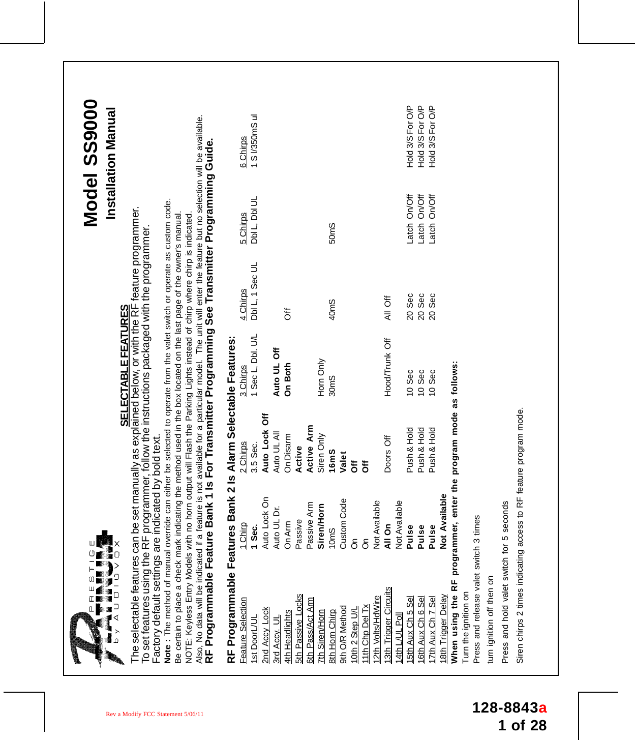
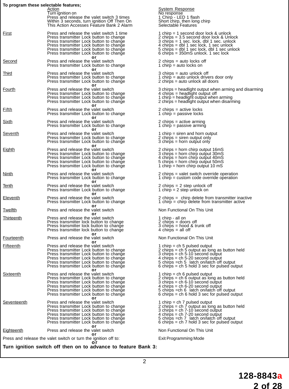
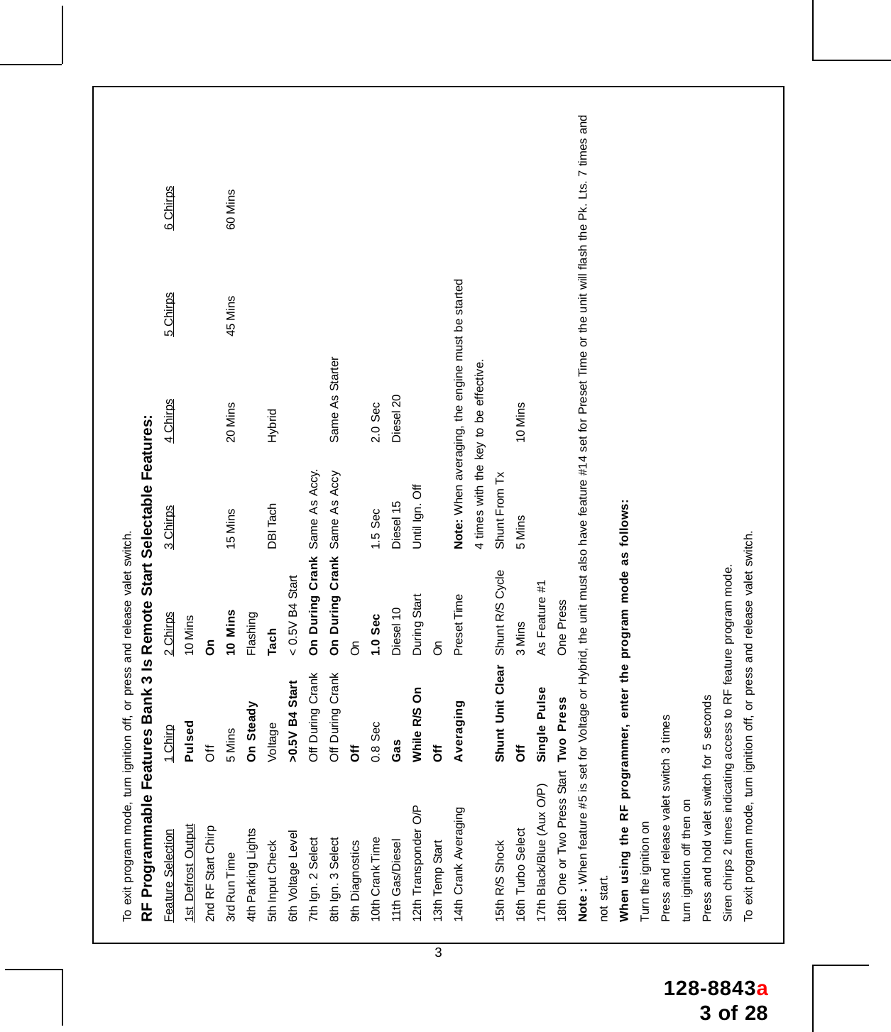
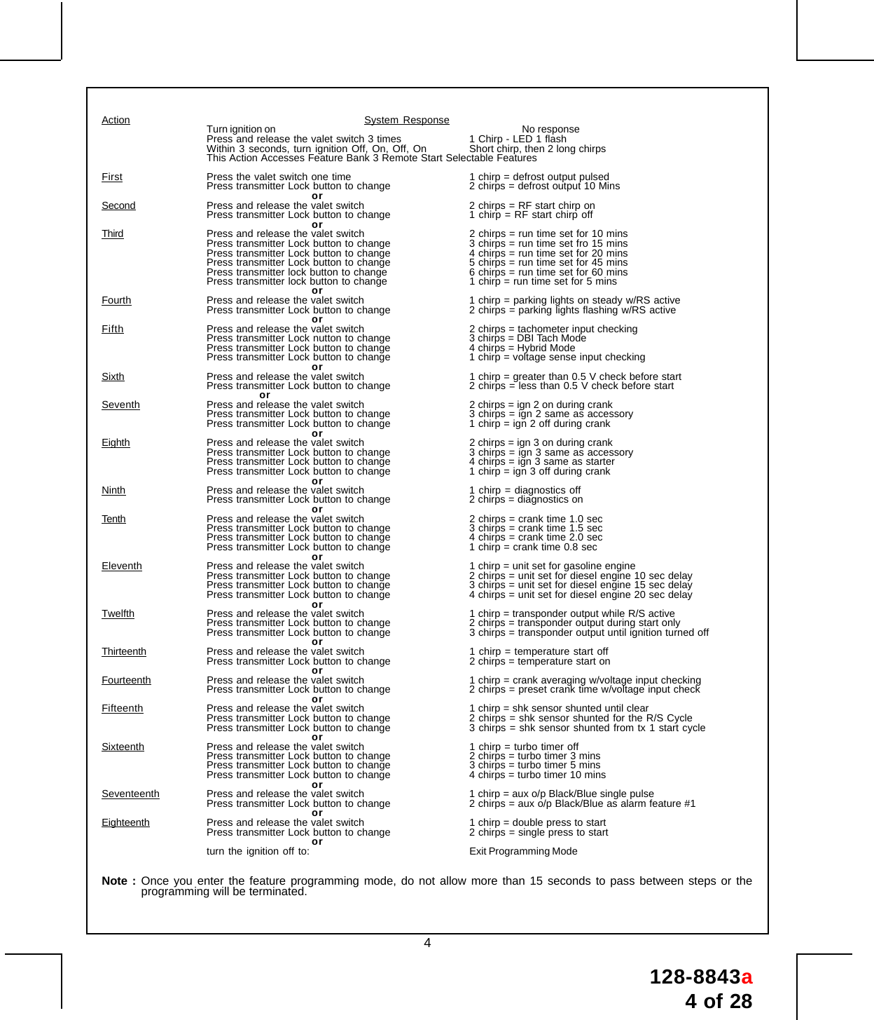
Nutek ATRKB Transmitter User Manual 1286388

Nutek Corporation Transmitter 1286388

User Manual

128-8843a1 of 281Model SS9000Installation ManualSELECTABLE FEATURESThe selectable features can be set manually as explained below, or with the RF feature programmer.To set features using the RF programmer, follow the instructions packaged with the programmer.Factory default settings are indicated by bold text.Note : The method of manual override can either be selected to operate from the valet switch or operate as custom code.Be certain to place a check mark indicating the method used in the box located on the last page of the owner's manual.NOTE: Keyless Entry Models with no horn output will Flash the Parking Lights instead of chirp where chirp is indicated.Also, No data will be indicated if a feature is not available for a particular model.  The unit will enter the feature but no selection will be available.RF Programmable Feature Bank 1 Is For Transmitter Programming See Transmitter Programming Guide.RF Programmable Features Bank 2 Is Alarm Selectable Features:Feature Selection 1 Chirp 2 Chirps 3 Chirps 4 Chirps 5 Chirps 6 Chirps1st DoorL/UL 1 Sec. 3.5 Sec. 1 Sec L, Dbl. U/L Dbl L, 1 Sec UL Dbl L, Dbl UL 1 S l/350mS ul2nd Accy Lock Auto Lock On Auto Lock Off3rd Accy. UL Auto UL Dr. Auto UL All Auto UL Off4th Headlights On Arm On Disarm On Both Off5th Passive Locks Passive Active6th Pass/Act Arm Passive Arm Active Arm7th Siren/Horn Siren/Horn Siren Only Horn Only8th Horn Chirp 10mS 16mS 30mS 40mS 50mS9th O/R Method Custom Code Valet10th 2 Step U/L On Off11th Chp Del Tx On Off12th Volts/HdWire Not Available13th Trigger Circuits All On Doors Off Hood/Trunk Off All Off14th L/UL Poll Not Available15th Aux Ch 5 Sel Pulse Push & Hold 10 Sec 20 Sec Latch On/Off Hold 3/S For O/P16th Aux Ch 6 Sel Pulse Push & Hold 10 Sec 20 Sec Latch On/Off Hold 3/S For O/P17th Aux Ch 7 Sel Pulse Push & Hold 10 Sec 20 Sec Latch On/Off Hold 3/S For O/P18th Trigger Delay Not AvailableWhen using the RF programmer, enter the program mode as follows:Turn the ignition onPress and release valet switch 3 timesturn ignition off then onPress and hold valet switch for 5 secondsSiren chirps 2 times indicating access to RF feature program mode.Rev a Modify FCC Statement 5/06/11
128-8843a2 of 282To program these selectable features;Action System ResponseTurn ignition on No responsePress and release the valet switch 3 times 1 Chirp - LED 1 flashWithin 3 seconds, turn ignition Off Then On Short chirp, then long chirpThis Action Accesses Feature Bank 2 Alarm Selectable FeaturesFirst Press and release the valet switch 1 time 1 chirp = 1 second door lock & unlockPress transmitter Lock button to change 2 chirps = 3.5 second door lock & UnlockPress transmitter Lock button to change 3 chirps = 1 sec. lock, dbl 1 sec. unlockPress transmitter Lock button to change 4 chirps = dbl 1 sec lock, 1 sec unlockPress transmitter Lock button to change 5 chirps = dbl 1 sec lock, dbl 1 sec unlockPress transmitter Lock button to change 6 chirps = 350mS unlock. 1 sec lockorSecond Press and release the valet switch 2 chirps = auto locks offPress transmitter Lock button to change 1 chirp = auto locks onorThird Press and release the valet switch 3 chirps = auto unlock offPress transmitter Lock button to change 1 chirp = auto unlock drivers door onlyPress transmitter Lock button to change 2 chirps = auto unlock all doorsorFourth Press and release the valet switch 3 chirps = headlight output when arming and disarmingPress transmitter Lock button to change 4 chirps = headlight output offPress transmitter Lock button to change 1 chirp = headlight output when armingPress transmitter Lock button to change 2 chirps = headlight output when disarmingorFifth Press and release the valet switch 2 chirps = active locksPress transmitter Lock button to change 1 chirp = passive locksorSixth Press and release the valet switch 2 chirps = active armingPress transmitter Lock button to change 1 chirp = passive armingorSeventh Press and release the valet switch 1 chirp = siren and horn outputPress transmitter Lock button to change 2 chirps = siren output onlyPress transmitter Lock button to change 3 chirps = horn output onlyorEighth Press and release the valet switch 2 chirps = horn chirp output 16mSPress transmitter Lock button to change 3 chirps = horn chirp output 30mSPress transmitter Lock button to change 4 chirps = horn chirp output 40mSPress transmitter Lock button to change 5 chirps = horn chirp output 50mSPress transmitter Lock button to change 1 chirp = horn chirp output 10 mSorNinth Press and release the valet switch 2 chirps = valet switch override operationPress transmitter Lock button to change 1 chirp = custom code override operationorTenth Press and release the valet switch 2 chirps = 2 step unlock offPress transmitter Lock button to change 1 chirp = 2 step unlock onorEleventh Press and release the valet switch 2 chirps =  chirp delete from transmitter inactivePress transmitter Lock button to change 1 chirp = chirp delete from transmitter activeorTwelfth Press and release the valet switch Non Functional On This UnitorThirteenth Press and release the valet switch 1 chirp - all onPress transmitter lock button to change 2 chirps = doors offPress transmitter lock button to change 3 chirps = hood & trunk offPress transmitter lock button to change 4 chirps = all offorFourteenth Press and release the valet switch Non Functional On This UnitorFifteenth Press and release the valet switch 1 chirp = ch 5 pulsed outputPress transmitter Lock button to change 2 chirps = ch 5 output as long as button heldPress transmitter Lock button to change 3 chirps = ch 5-10 second outputPress transmitter Lock button to change 4 chirps = ch 5-20 second outputPress transmitter Lock button to change 5 chirps =ch 5  latch on/latch off outputPress transmitter Lock button to change 6 chirps = ch 5 hold 3 sec for pulsed outputorSixteenth Press and release the valet switch 1 chirp = ch 6 pulsed outputPress transmitter Lock button to change 2 chirps = ch 6 output as long as button heldPress transmitter Lock button to change 3 chirps = ch 6-10 second outputPress transmitter Lock button to change 4 chirps = ch 6-20 second outputPress transmitter Lock button to change 5 chirps =ch 6  latch on/latch off outputPress transmitter Lock button to change 6 chirps = ch 6 hold 3 sec for pulsed outputorSeventeenth Press and release the valet switch 1 chirp = ch 7 pulsed outputPress transmitter Lock button to change 2 chirps = ch 7 output as long as button heldPress transmitter Lock button to change 3 chirps = ch 7-10 second outputPress transmitter Lock button to change 4 chirps = ch 7-20 second outputPress transmitter Lock button to change 5 chirps =ch 7  latch on/latch off outputPress transmitter Lock button to change 6 chirps = ch 7 hold 3 sec for pulsed outputorEighteenth Press and release the valet switch Non Functional On This UnitorPress and release the valet switch or turn the ignition off to: Exit Programming ModeorTurn ignition switch off then on to advance to feature Bank 3:
128-8843a3 of 283To exit program mode, turn ignition off, or press and release valet switch.RF Programmable Features Bank 3 Is Remote Start Selectable Features:Feature Selection 1 Chirp 2 Chirps 3 Chirps 4 Chirps 5 Chirps 6 Chirps1st Defrost Output Pulsed 10 Mins2nd RF Start Chirp Off On3rd Run Time 5 Mins 10 Mins 15 Mins 20 Mins 45 Mins 60 Mins4th Parking Lights On Steady Flashing5th Input Check Voltage Tach DBI Tach Hybrid6th Voltage Level >0.5V B4 Start < 0.5V B4 Start7th Ign. 2 Select Off During Crank On During Crank Same As Accy.8th Ign. 3 Select Off During Crank On During Crank Same As Accy Same As Starter9th Diagnostics Off On10th Crank Time 0.8 Sec 1.0 Sec 1.5 Sec 2.0 Sec11th Gas/Diesel Gas Diesel 10 Diesel 15 Diesel 2012th Transponder O/P While R/S On During Start Until Ign. Off13th Temp Start Off On14th Crank Averaging Averaging Preset Time Note: When averaging, the engine must be started4 times with the key to be effective.15th R/S Shock Shunt Unit Clear Shunt R/S Cycle Shunt From Tx16th Turbo Select Off 3 Mins 5 Mins 10 Mins17th Black/Blue (Aux O/P) Single Pulse As Feature #118th One or Two Press Start Two Press One PressNote : When feature #5 is set for Voltage or Hybrid, the unit must also have feature #14 set for Preset Time or the unit will flash the Pk. Lts. 7 times andnot start.When using the RF programmer, enter the program mode as follows:Turn the ignition onPress and release valet switch 3 timesturn ignition off then onPress and hold valet switch for 5 secondsSiren chirps 2 times indicating access to RF feature program mode.To exit program mode, turn ignition off, or press and release valet switch.
128-8843a4 of 284Action System ResponseTurn ignition on No responsePress and release the valet switch 3 times 1 Chirp - LED 1 flashWithin 3 seconds, turn ignition Off, On, Off, On Short chirp, then 2 long chirpsThis Action Accesses Feature Bank 3 Remote Start Selectable FeaturesFirst Press the valet switch one time 1 chirp = defrost output pulsedPress transmitter Lock button to change 2 chirps = defrost output 10 MinsorSecond Press and release the valet switch 2 chirps = RF start chirp onPress transmitter Lock button to change 1 chirp = RF start chirp offorThird Press and release the valet switch 2 chirps = run time set for 10 minsPress transmitter Lock button to change 3 chirps = run time set fro 15 minsPress transmitter Lock button to change 4 chirps = run time set for 20 minsPress transmitter Lock button to change 5 chirps = run time set for 45 minsPress transmitter lock button to change 6 chirps = run time set for 60 minsPress transmitter lock button to change 1 chirp = run time set for 5 minsorFourth Press and release the valet switch 1 chirp = parking lights on steady w/RS activePress transmitter Lock button to change 2 chirps = parking lights flashing w/RS activeorFifth Press and release the valet switch 2 chirps = tachometer input checkingPress transmitter Lock nutton to change 3 chirps = DBI Tach ModePress transmitter Lock button to change 4 chirps = Hybrid ModePress transmitter Lock button to change 1 chirp = voltage sense input checkingorSixth Press and release the valet switch 1 chirp = greater than 0.5 V check before startPress transmitter Lock button to change 2 chirps = less than 0.5 V check before startorSeventh Press and release the valet switch 2 chirps = ign 2 on during crankPress transmitter Lock button to change 3 chirps = ign 2 same as accessoryPress transmitter Lock button to change 1 chirp = ign 2 off during crankorEighth Press and release the valet switch 2 chirps = ign 3 on during crankPress transmitter Lock button to change 3 chirps = ign 3 same as accessoryPress transmitter Lock button to change 4 chirps = ign 3 same as starterPress transmitter Lock button to change 1 chirp = ign 3 off during crankorNinth Press and release the valet switch 1 chirp = diagnostics offPress transmitter Lock button to change 2 chirps = diagnostics onorTenth Press and release the valet switch 2 chirps = crank time 1.0 secPress transmitter Lock button to change 3 chirps = crank time 1.5 secPress transmitter Lock button to change 4 chirps = crank time 2.0 secPress transmitter Lock button to change 1 chirp = crank time 0.8 secorEleventh Press and release the valet switch 1 chirp = unit set for gasoline enginePress transmitter Lock button to change 2 chirps = unit set for diesel engine 10 sec delayPress transmitter Lock button to change 3 chirps = unit set for diesel engine 15 sec delayPress transmitter Lock button to change 4 chirps = unit set for diesel engine 20 sec delayorTwelfth Press and release the valet switch 1 chirp = transponder output while R/S activePress transmitter Lock button to change 2 chirps = transponder output during start onlyPress transmitter Lock button to change 3 chirps = transponder output until ignition turned offorThirteenth Press and release the valet switch 1 chirp = temperature start offPress transmitter Lock button to change 2 chirps = temperature start onorFourteenth Press and release the valet switch 1 chirp = crank averaging w/voltage input checkingPress transmitter Lock button to change 2 chirps = preset crank time w/voltage input checkorFifteenth Press and release the valet switch 1 chirp = shk sensor shunted until clearPress transmitter Lock button to change 2 chirps = shk sensor shunted for the R/S CyclePress transmitter Lock button to change 3 chirps = shk sensor shunted from tx 1 start cycleorSixteenth Press and release the valet switch 1 chirp = turbo timer offPress transmitter Lock button to change 2 chirps = turbo timer 3 minsPress transmitter Lock button to change 3 chirps = turbo timer 5 minsPress transmitter Lock button to change 4 chirps = turbo timer 10 minsorSeventeenth Press and release the valet switch 1 chirp = aux o/p Black/Blue single pulsePress transmitter Lock button to change 2 chirps = aux o/p Black/Blue as alarm feature #1orEighteenth Press and release the valet switch 1 chirp = double press to startPress transmitter Lock button to change 2 chirps = single press to startorturn the ignition off to: Exit Programming ModeNote : Once you enter the feature programming mode, do not allow more than 15 seconds to pass between steps or theprogramming will be terminated.
128-8843a5 of 285This Remote Start/Alarm System is designed to be used with Automatic Transmission- Fuel InjectionVehicles Only!  The unit provides a selectable ignition control that allows a number of selectable timed outputsfor glow plug preheat in addition to a "Wait To Start Input" either of which may be required for certain dieselvehicles, (see selectable feature #11 Bank 3 & or Green/Yellow Wire).  If the diesel engine has a instant fire, (noglow plug preheat system), feature #11 of Bank 3 should remain in the default Gasoline mode setting. Fordiesel applications, consult your dealer for the type of ignition system used in your particular vehicle.Regardless of the vehicle, Gasoline or Diesel, for every installation, the vehicle MUST HAVE a TachSignal Input, Automatic Transmission and Fuel Injection.INSTALLATION OF THE MAJOR COMPONENTS:CONTROL MODULE:Select a mounting location inside the passenger compartment (up behind the dashboard).  The mountinglocation selected must be within 24" of the ignition switch wiring harness to allow connection of the 6 pinmain wiring harness.Be certain that the chosen location will not interfere with proper operation of the vehicle.  Avoid mountingthe module to or routing the wiring around the steering shaft/column, as the module or wiring may wraparound or block the steering wheel preventing proper control of the vehicle.  Secure the module in thechosen location using cable ties or screws as necessary.Do Not Mount The Module In The Engine Compartment, as it is not waterproof.SIREN:Select a location in the engine compartment that is not accessible from below the vehicle.  The selectedlocation must be clear of hot or moving parts within the engine compartment  The siren must be pointeddownward to prevent water retention and the flared end must be pointed away from and out of the enginecompartment for maximum sound distribution.  Before securing the siren, check behind your chosenlocation to assure that the mounting screws will not penetrate any factory wiring or fluid lines. Secure thesiren mounting bracket using #8 self taping screws or by first using the mounting bracket as a template,scribe or mark the mounting holes.  Drill the marked holes using a 1/8" drill bit, then mount the siren using#8 sheet metal screws.HOOD PIN SWITCH:The pin switche included in this package is intended for protecting the hood area of the vehicle.  In allcases, the switch must be mounted to a grounded metal surface.  When the pin switch is activated, (hoodopen),  it will supply a ground to the input wire activating the alarm.  In addition, the hood switch is requiredfor the safety shut down of the remote start unit.  If the vehicle is being worked on,  this hood switchprevents the remote start activation even if the RF command to start is issued.  This switch must beinstalled in all applications.  Failure to do so may result in personal injury or property damage.Mount the switch in a location away from water drain paths.  If necessary,  an optional bracket may beused to move the switch away from rain gutters or allow mounting to the firewall behind the hood seal.  Inboth cases the switch must be set up to allow the hood to depress the switch at least 1/4 inch when thehood is closed and fully extended when the hood is opened. For direct mounting, a 1/4 inch hole must bedrilled.  Carefully check behind the chosen location to insure the drill will not penetrate any existing factorywiring or fluid lines.Drill a 1/4" hole in the desired location and thread the pin switch into it using a 7/16" nut driver or deep wellsocket. If using the mounting bracket, first secure the bracket to the desired location and secure the pinswitch in the pre-threaded mounting bracket hole.
128-8843a6 of 286THE PUSH-BUTTON/LED/RECEIVER/ANTENNA ASSEMBLY:The Spread Spectrum Receiver Antenna Assembly provided with this unit allows routing from below thedash board for maximum operating range.  Choose a location above the belt line (dashboard) of the vehiclefor best reception.  Special considerations must be made for windshield glass as some newer vehiclesutilize a metallic shielded window  glass that will inhibit or restrict RF reception.  In these vehicles, routethe antenna toward a rear window location for best reception.  Secure the antenna with double stick tapeprovided.  After securing the antenna with tape, we advise also securing a section of the antenna cable toa fixed support.  This will prevent the antenna from dropping down in case the double stick tape is exposedto extreme heat which may loosen it's gummed surface.  Route the 6 pin connector toward the controlmodule using caution not to pinch the cable as this will cause poor or no RF reception to the controlmodule.SHOCK SENSOR:Select a centrally located,  solid mounting surface for the shock sensor that will allow consistent operationfrom all areas of the vehicle.  The selected location must be within 18" of the control module to allowrouting and connecting of the 4 pin harness.  Secure the shock sensor to the chosen location using two #8self tapping sheet metal screws.  The sensor can also be secured to an existing dash brace using cabletie straps.  Whichever mounting method is used be sure to allow access to the sensitivity adjustmentpotentiometer for use later in the installation.STARTER INHIBIT RELAY:Select a mounting location within 12" of the ignition switch's low current start solenoid wire.  Secure therelay to an existing harness in the chosen location using a cable tie around the relay's wiring harness.CAUTION! Do not wire tie the metal bracket to an existing wiring harness as vibration may causechaffing and shorting damaging the factory wiring.  If an existing harness is not available thensecure the relay's metal mounting tab to an under dash metal brace with a #8 self tappingsheet metal screw.  Wire the relay as per the diagram found later in this manual.This unit is to be used in vehicles with AUTOMATIC TRANSMISSIONS only!  Although this combinationAlarm/Remote Start unit is a sophisticated system with many advanced features, IT MUST NOT beinstalled into a vehicle with a manually operated transmission.  Doing so may result in serious personalinjury and property damage. IMPORTANT!DO NOT PLUG THE SIX PIN MAIN POWER HARNESS OR THE MULTI PIN INPUT / OUTPUT HARNESSINTO THE CONTROL MODULE UNTIL ALL CONNECTIONS TO THE VEHICLE HAVE BEEN MADE.AFTER SELECTING YOUR TARGET WIRES AS DEFINED BELOW, DISCONNECT THE NEGATIVEBATTERY CABLE FROM THE VEHICLE BATTERY PRIOR TO MAKING ANY CONNECTIONS.Note:  Do not remove the fuse holders from this wire harness.  Fuses must be used and locatedas close as possible to the power source for adequate protection of the vehicle.
128-8843a7 of 287WIRING THE 6 PIN MAIN POWER HARNESS:WIRING THE 6 PIN MAIN POWER HARNESS:Note:  Do not remove the fuse holders from this wire harness.  Fuses must beused and located as close as possible to the power source for adequate protec-tion of the vehicle.Fused RED w/ WHITE TRACE WIRE:  + 12 volt Battery 1 SourceLocate the vehicle battery wire(s) at the ignition switch.  Verification: These wires will register voltage in all positionsof the ignition switch.  Connect the Red w/White wire to the vehicle's battery wire.  This wire provides power for thecontrol circuit as well as the ignition 1 and ignition 2 relays.Fused RED WIRE:  + 12 Volt Battery 2 SourceLocate the vehicle battery wire(s) at the ignition switch.  Verification: These wires will register voltage in all positionsof the ignition switch.  Connect the Red  wire to the vehicle's battery wire.  This wire provides power for the start relayand the accessory relay.IMPORTANT!IT IS THE RESPONSIBILITY OF THE INSTALLING TECHNICIAN TO DETERMINE THE LOAD FACTOR OF THEVEHICLES ELECTRICAL CIRCUITS WHEN THE VEHICLE IS RUNNING AND TO ADEQUATELY FUSE THE TWOPOWER WIRES BASED ON THAT LOAD.  IF THE VEHICLE, RUNNING UNDER LOAD WITH THE AIR CONDI-TIONER, HEATER BLOWER MOTOR, AND ACCESSORIES EXCEEDS 24 AMPS CONTINUOUS, WE RECOMMENDTHAT TWO FUSES BE USED IN COMBINATION ON EACH POWER WIRE AS SHOWN BELOW.  FOR ADDITIONALINFORMATION SEE TECH UPDATE ISSUED 9/30/96.I
128-8843a8 of 288YELLOW Wire:  Starter OutputCareful consideration for the connection of this wire must be made to prevent the vehicle fromstarting while in gear.  Understanding the difference between a mechanical and an electricalNeutral Start Switch will allow you to properly identify the circuit and select the correct installa-tion method.   In addition you will realize  why  the connection of  the safety wire is required forall mechanical switch configurations.Failure to make this connection properly can result in personal injury and property damage.In all installations it is the responsibility of the installing technician to test the remote start unit and  ensurethat the vehicle cannot start via RF control in any gear selection other than park or neutral.In both mechanical and electrical neutral start switch configurations, the connection of  the Yellow wire willbe made to the low current start solenoid wire of the ignition switch harness.  This wire will have +12 voltswhen the ignition switch is turned to the start (crank) position only.  This wire will have 0 volts in all otherignition switch positions.NOTE:  This wire must be connected to the vehicle side of the starter cut relay (when used).  For theelectrical neutral switch configuration, this connection must be made between the starter inhibit relay,( when used ) and the neutral safety switch as shown in the following diagram.Failure to connect this wire to the ignition switch side of the of the neutral safety switch can result inpersonal injury and property damage.SEE NEUTRAL START SAFETY TEST FOR FURTHER DETAILS.YELLOW START WIRE DETAILBLUE Wire:  Ignition 1 OutputConnect this wire to the ignition 1 wire from the ignition switch.  This wire will show +12 volts when theignition key is turned to the "ON" or "RUN" and the "START" or CRANK" positions, and will have 0 voltswhen the key is turned to the "OFF" and "ACCESSORY" positions.For Diesel Applications, this wire must be connected to the ignition circuit that powers the glow plugs if thevehicle requires glow plug pre-heating. (See selectable feature Bank 3 #11)
128-8843a9 of 289GREEN Wire:  Ignition 2 OutputConnect this wire to the ignition 2 wire from the ignition switch.  This wire will show + 12 volts when theignition key is turned to the "ON" or "RUN" position and is some cases the "START" or CRANK" position.This wire will show  0 volts when the key is turned to the "OFF" and "ACCESSORY" positions.NOTE: See programming information (Bank 3 Selection #2) concerning this wire to allow output during the"START" mode.VIOLET Wire:  Accessory OutputConnect this wire to the Accessory wire from the ignition switch.  This wire will show + 12 volts when theignition switch is turned to the  "ACCESSORY" or "ON" and "RUN" positions, and will show 0 volts whenthe key is turned to the "OFF" and "START" or "CRANK" positions.WIRING THE 4 PIN ALTERNATE IGNITION HARNESSORANGE/BLACK Wire: Parking Brake InputThis wire is used only when the turbo timer mode, Bank 3, feature # 16 is selected ON.  This input insuresthat the vehicle parking brake is applied whenever the vehicle is set up for and the turbo timer circuit is used.This input must switch to ground when the vehicle's parking brake is applied. Connect the Orange/Black wireto the negative output of the vehicle's parking brake switch.RED/BLACK Wire: + 12 Volts InputNote: The Red/Black and Pink are dry contacts and may be used for negative switching when necessary.Connecting the Red/Black to chassis ground will result in Pink being ground when the R/S is activated.This input is to be connected to a separate, (Other than the wire Red or Red/White is connected to), constanton + 12 volt source which will supply + 12 volt power to the additional ignition output, (Pink), wire.  Connectthis wire to a separate + 12 Volt source.PINK Wire: Additional Ignition OutputThis wire can be used as an additional + 12 Volt ignition output supplied by the Red/Black wire.  This outputcan be selected to be on or off during the start cycle.  (See feature bank 3 selection # 8)  Connect this wireto the third ignition circuit in the vehicle and set the selectable feature # 8 of Bank 3 according to the wayin which the vehicle's ignition switch operates.Note:  Do not remove the fuse holders from this wire harness.  Fuses must beused and located as close as possible to the power source for adequate pro-tection of the vehicle.
128-8843a10 of 2810White w/ Black Trace Wire: (+) Siren OutputThis is the positive siren feed wire.  Route this wire through a grommet in the firewall to the sirenlocation.  Connect the White w/ Black Trace wire to the Red wire of the Siren.  Secure the Black wireof the Siren to a known chassis ground or solid clean metal surface.WIRING CONNECTIONS:  Multi Pin Accessory Input/Output HarnessWhite w/ Red Trace Wire: Parking Light Flasher FeedThis wire is the common contact of the on board parking light flasher relay.  If the vehicle you are workingon has +12 volt switched parking lights, connect this wire to a fused + 12 volt source. (Max. 15 Amps)NOTE: If the vehicle's parking lights are ground switched, connect this wire to chassis ground.White Wire: Parking Light Flasher OutputThis wire is the normally open contact of the on board parking light flasher relay.  Connect this wire to thevehicle parking light feed wire. See diagram below for details on wiring positive switched parking lightcircuits. Parking Light Wiring Detail
128-8843a11 of 2811Siren Wiring Detail(-) TO VEHICLE'S CHASSIS GROUNDTO WHITE w/BLACK WIRE OF MODULEPurple Wire: (+) Door Trigger InputIf the vehicle's door courtesy light switches + 12 volts when the door is opened, (Some Fords and someImports), you must connect this wire to the positive output from one of the vehicle's door pin switches.  Inmost cases, the Purple wire will need to be connected to only one door switch no matter how many doorsthe vehicle has as most door lighting circuits are wired in parallel.  This wire will be shunted when remotestarting the vehicle and will remain shunted, if active, while running under command of the remote start.  Ifthis wire is active when the system is armed, the siren will emit three chirps.  When the zone clears, thesiren will emit 1 chirp to confirm full arming. See below for wiring details.Note for vehicles with interior delay lighting see programming under title "Completing The Installation".Positive Door Switch Wiring DetailDark Green Wire: (-) Instant Trigger InputThis is the instant on ground trigger input wire.  This wire must be connected to the hood and trunk pinswitches previously installed.NOTE: This wire will be shunted when remote control channel 3 is accessed, (trunk release).  This wirewill remain shunted all the while there is ground present and for 5 seconds after the ground is removed.This allows the operator to open the trunk via the remote transmitter without having to first disarm thealarm system.   See below for wiring detail.Hood Pin Switch DetailLight Blue Wire:  Ground Output While Running Under Remote Start ControlThis wire provides a  300mA ground output that becomes active 3 seconds before the Remote StartUnit initializes and remains grounded while running plus an additional 4 seconds after the Remote StartUnit turns off.  In all of the applications described below, a relay will be required.The Light Blue wire can be used to accommodate the following situations:
128-8843a12 of 2812A. Shock Sensor By Pass:If there is a Non Plug in Shock Sensor used with the alarm system and it is not shunted during theRemote Start activation period, then vibration from the running vehicle can cause the alarm to trigger.  Inthis case, connect the Light Blue Wire to terminal #86 of a external relay.  Connect terminal # 85 of therelay to a fused + 12 volt battery source.  Cut the shock sensor trigger wire and connect one end of thecut wire to terminal #30 and the other end of the cut wire to terminal #87a.  Just before the Remote Startunit is activated, the relay contacts will open, preventing the shock sensor's operation until the RemoteStart unit shuts off.B. Additional Ignition Output:Some newer vehicles more than three ignition outputs to start and keep the vehicle's engine running.  Ifthis is the case, connect the Light Blue wire to terminal #86 of an external relay.  Connect terminal # 30& # 85 to a fused + 12 volt battery source rated for a minimum of 25 Amp. Connect terminal # 87 to thethird ignition wire in the vehicle.C. GM VATS Key Override:If the vehicle has the General Motors VATS system installed, you will need to bypass the system whilethe vehicle is operating under the control of the Remote Start Unit.  To Do This:1. Measure the resistance of the resistor pellet on the ignition key then select a resistor within 5% of thekey's value from the resistor pack supplied.2. Locate the pair of  VATS wires in the vehicle, usually a pair of thin gauge wires running from theignition switch to the VATS control module.NOTE:  These wires are typically White w/ Black trace and Violet w/ Yellow trace, however in later modelCadillacs, they are run through an orange sleeve, and are either both Black, both Yellow, or both Whitewires.  Consult the factory service manual for additional information.3. Connect the Light Blue Wire from the Remote Start Unit to terminal #86 of an external relay.  Connectterminal #85 of the relay to a fused + 12 volt battery source.4. Cut (#1) wire (as shown), and connect the ignition switch side of the cut wire to terminal #87a of therelay. Connect the other side of the (#1) wire to terminal #30.5. Connect the previously selected resistor from terminal #87 to the second (#2) wire (as shown).NOTE: The above information and following diagram is for the GM VATS system only.  For GM PASSLOCK System you will require the Audiovox AS-PASS II Module.General Motors VATS By-Pass DiagramGreen w/ White trace Wire:  Entry Illumination Ground OutputThis wire provides a 30 second ground output (300 mA Max.) whenever the remote is used to disarm thealarm or to unlock the doors and provides a continuous pulsed output whenever the alarm is triggered.This wire should be connected to an external relay  and wired  to the vehicles interior entry lightingwhenever the optional Interior Illumination circuit is desired.  See below for relay wiring details.
128-8843a13 of 2813Entry Illumination DetailGrey w/ Black Trace Wire:  Negative Inhibit Input Plus Trigger When ArmedThe Grey w/ Black Trace wire provides an instant shutdown for the Remote Start Control Module wheneverit is grounded it also trigger the alarm when armed.  Connect the Grey w/ Black trace wire to the hood pinswitch previously installed.  This wire must be routed through  a grommet in the firewall and connected tothe hood pin switch.  If the pin switch is to be used with an alarm system, connect this wire using the diodeassembly provided.IMPORTANT! This connection is a safety wire and must be connected as shown and tested as specified.Failure to do so may result in personal injury or property damage. See detail of wiring in the followingdiagram.  This wire may also be used if the vehicle brake light circuit switches ground to the brake lights.An isolation diode must be used for ground switched brake light circuits and must be connected to theoutput of the brake switch.Grey w/ Black Trace Negative Inhibit Safety Shut Down DetailOrange Wire:  Ground When Armed OutputThis wire provides a 300 mA ground output when the alarm circuit is armed to control the starter inhibitrelay.  Connect the Orange wire to terminal #86 (orange wire) of the relay provided.  Connect terminal#85 (red wire) of the relay to an ignition wire in the vehicle that is +12 volts when the ignition switch isturned to the on and start positions and off when the key is off.  Locate and cut the low current startsolenoid wire found at the vehicles ignition switch harness.  This wire will have + 12 volts when theignition key is moved to the start (crank) position and will have 0 volts in all other key positions.  Con-nect one side of the cut wire to terminal #87a ( Black wire) of the relay.  Connect the other side of thecut wire to terminal #30 (White/Black wire) of the relay.  See below for detail of wiring, also see YellowStart  wire detail for connection to vehicle considerations.
128-8843a14 of 2814Brown w/ Black Trace Wire:  Positive Inhibit Input Plus Trigger When ArmedThe Brown w/ Black Trace wire provides an instant shutdown for the Remote Start Control module when-ever it gets + 12 volts also triggers the alarm when armed.  If the Brake lights switch in the vehicleswitches + 12 volts to the brake light circuit, connect the Brown w/ Black trace wire to the output side ofthe brake switch.  This will allow the Remote Start to shut down if an attempt is made to operate thevehicle without the key while running under the control of the Remote Start.  In most vehicles, in order toshift into gear, the brake pedal must be depressed.  The brake input will in turn cause the remote start unitto shut off.  See detail in the following diagram for wiring the brake light circuit.Brake Switch Positive Shutdown DetailBlack Wire: Chassis Ground SourceConnect the Black wire to a known vehicle ground source  or to a solid clean metal part of the chassis.  Becertain to remove any paint or grease and secure this wire with a self tapping screw and ring terminal.Chassis Ground Connection DetailStarter Inhibit Wiring DetailBlackWhite/Black
128-8843a15 of 2815Green w/ Orange Trace Wire: Tachometer Input SignalThis wire will continually monitor the engine's tach rate while the unit is under power of the Remote Startmodule.  This wire will be routed to the vehicle ECM tach input or through the firewall into the enginecompartment and connect to the negative side of the ignition coil.  This Remote Start unit learns the tachrate of the vehicle and in most cases will operate properly from one multi coil pack regardless of the numberof cylinders.  If the vehicle has a single coil unit for each cylinder, it may be necessary to connect this wireto more than one cylinder for proper tach reference.  See multi coil wiring detail shown later in this manualfor additional information.Note: For Hybrid mode, Bank 3 feature selection 5, this connection is not used, the unit will start the vehicleand run the allotted time based on feature selection and crank duration.Tachometer Input Wiring DetailBrown Wire:  Negative Door TriggerIf the vehicle's door courtesy light switches ground when the door is opened, (Most GMs and Imports), youmust connect this wire to the negative output from one of the vehicle's door pin switches.  In most cases theBrown wire will need to be connected to only one door switch no matter how many doors the vehicle has asmost door lighting circuits are wired in parallel.  This wire will be shunted when remote starting the vehicleand will remain shunted, if active, while running under command of the remote start.  If this wire is activewhen the system is armed, the siren will emit three chirps.  When the zone clears, the siren will emit 1chirp to confirm full arming. See below for wiring detail.Note for vehicles with interior delay lighting see programming under title "Completing The Installation".Negative Door Switch Wiring DetailDark Blue Wire:  Delayed 300mA Pulsed  Channel 3 OutputThe Dark Blue wire supplies a 300mA ground pulsed output whenever channel three of the receiver isaccessed.  Pressing the pre-programmed transmitter button for three seconds will access channel two.This is a low current output and must be connected to a relay to supply power to the trunk release or thecircuit you wish to control.  Connect the Dark Blue wire to terminal # 86 of a VF45F11 P&B relay orequivalent.  Connect terminal  # 85  of the relay to a fused + 12 volt source.  Connect the common,normally open, and normally closed contacts of the relay to perform the selected function of channel 3.See below for relay wiring detail.
128-8843a16 of 2816Channel 3 Relay Wiring DetailGreen w/ Black Trace Wire:  300mA  Latched Channel 4 OutputThe Green w/ Black Trace wire supplies a  300 mA switched output whenever channel four of the receiveris accessed.  Pressing the pre-programmed transmitter button(s) will access channel four and will remainactive, for up to 20 seconds, as long as the transmitter button(s) is held.  This is a low current output andmust be connected to a relay to supply power to the device you intend to control.  Connect Green w/ BlackTrace wire to terminal #86 of a VF45F11 P&B relay or equivalent.  Connect terminal #85 of the relay to afused + 12 volt source.  Connect the common, normally open, and normally closed contacts of the relay toperform the selected function of the channel 4 output.NOTE:  This wire also can be used for defrost activation as dictated by the setting of feature # 1 of Bank 3.Anytime the vehicle is running under control of the Remote Start and Channel 4 is activated, then depen-dent on the selection of this feature, Green/Black will be activated as a pulse for 1 second, or for 10minutes.  Note this wire will not operate when the vehicle is running under the power of the ignition key,only while under the control of the remote start or if not used for defrost then an output will occur asindicated above.Dark Blue/Black Trace Wire: External Trigger InputThe Dark Blue/Black trace wire allows the remote start unit to be activated from an external source.  Theintent of this wire is to allow the unit to be controlled from a "POSSE/CAR-LINK" paging system or similardevice.  When this wire receives a ground pulse, the unit will start the vehicle. Connect this wire to a groundpulsed output from the controlling circuit.Black w/ White Trace Wire : 300 mA Horn OutputThe black w/ white trace wire is provided to beep the vehicle’s horn. This is a transistorized low currentoutput, and should only be connected to the low current ground output from the vehicle’s horn switch.If the vehicle uses a + 12 VDC horn switch, then connect the black w/ white trace wire to terminal 86 of theAS 9256 relay ( or an equivalent 30 Amp automotive relay ), and connect relay terminal 85 to a fused+ 12 VDC battery source. Connect relay terminal 87 to the vehicle’s horn switch output, and connect relayterminal 30 to a fused + 12 VDC battery source.White w/ Blue Trace Wire: Low Current (-) Ground Headlight OutputThe White w/ Blue Trace wire is provided to operate the optional headlamp illumination feature of thesystem.  This is a low current (300mA) output and must be connected to an external relay to control thehigh current switching circuit of the vehicle's headlamps.  To use this option, connect the White /w BlueTrace wire to terminal # 86 of a P&B VF45F11 relay or equivalent.  Connect Terminals #85 and # 30 to afused + 12 Volts source with a current capability equal to or in excess of the factory headlamp fuse.Connect terminal # 87 of the relay to the switched + 12 volt wire feeding the vehicle's headlamp circuit.NOTE:  For ground switched headlamp circuits,  Connect the White /w Blue Trace wire to terminal # 86 ofa P&B VF45F11 relay or equivalent.  Connect Terminal #85  to a fused + 12 Volts source. Connect terminal# 30 to a clean chassis ground.  Connect terminal # 87 to the ground switched headlamp control wire in thevehicle.Orange w/ White Trace Wire : 300 mA Ground Output When Disarmed - N. O. Starter Disable(Optional Relay Required).This wire is provided to control the starter cut relay. Connect the orange w/white wire to terminal 86 of therelay. Connect relay terminal 85 to an ignition wire in the vehicle that is live when the key is in the on andcrank positions, and off when the key is in the off position. ( This is typically where the yellow, (ignition),wire of an alarm would be connected ).  Cut the low current starter solenoid wire in the vehicle, and connectone side of the cut wire to relay terminal 87. Connect the other side of the cut wire to relay terminal 30.
128-8843a17 of 2817NOTE : This is a normally opened starter cut arrangement, when power is removed from thesecurity system, the starter disable feature will remain operational, and the vehicle will not start.Audiovox does not recommend using the Orange w/ White trace wire to interrupt anything but thestarting circuit of the vehicle.Lt Green Wire: (-)  Instant Trigger Zone 1This is a instant on ground trigger input intended for the connection of optional triggering devices.  Theground trigger output wire of motion detectors, microwave detectors, or glass break detectors, can beconnected to this Light Green trigger input wire.Lt Blue/Green Wire : DELAYED 300 mA PULSED OUTPUT / CHANNEL 5The light blue/green wire pulses to ground via an independent RF channel from the keychain transmitter.This is a transistorized, low current output, and should only be used to drive an external relay coil.WARNING: Connecting the light blue/green to the high current switched output of trunk release circuits,some remote start trigger inputs, will damage the control module.Connect the light blue/green to terminal 86 of the AS - 9256 relay (or equivalent 30 A automotive relay) andwire the remaining relay contacts to perform the selected function of channel 5.Lt Blue/Black Wire : DELAYED 300 mA PULSED OUTPUT / CHANNEL 6The light blue/green wire pulses to ground via an independent RF channel from the keychain transmitter.This is a transistorized, low current output, and should only be used to drive an external relay coil.WARNING: Connecting the light blue/black to the high current circuits,  will damage the control module.Connect the light blue/black to terminal 86 of the AS - 9256 relay (or equivalent 30 A automotive relay) andwire the remaining relay contacts to perform the selected function of channel 6.Blue/Red Wire : DELAYED 300 mA PULSED OUTPUT / CHANNEL 7The light blue/red wire pulses to ground via an independent RF channel from the keychain transmitter. Thisis a transistorized, low current output, and should only be used to drive an external relay coil.WARNING: Connecting the light blue/red to the high current circuits, will damage the control module.Connect the light blue/red to terminal 86 of the AS - 9256 relay (or equivalent 30 A automotive relay) and wirethe remaining relay contacts to perform the selected function of channel 7.Green/Yellow Wire:  DIESEL WAIT TO START INPUTThe green/yellow wire, when connected to the wire that get + 12 volts during the glow plug preheat stage willdelay the starter output until this wire drops the 12 volts.  In other words, in a Diesel vehicle with glow plugpreheat circuit, when the ignition is turned on, the vehicle will not crank until the glow plugs are hot enoughto fire the atomized fuel oil when injected into the cylinder. By connecting this wire to the glow plug + 12 voltwire, when the remote start unit activates the ignition one output, the glow plug output also activates.  Theremote start sees the green/yellow with positive voltage and waits for this to go inactive( drop the 12 volts)before activating the starter motor.  If this wire is not used or you have difficulty accessing the glow plugpreheat circuit, you may elect to utilize the Diesel timed output as specified in Remote Start feature selec-tion #9. NOTE: If green/yellow is used, it will override or negate any setting of feature #9.WIRING THE 4 PIN AUXILIARY OUTPUT HARNESSThe auxiliary 4 pin connector provides low current outputs to control various functions in the vehicle duringdifferent stages of the Remote Start unit's operation.  Understanding these outputs and the time in whichthey occur will allow you to determine if they are needed for the particular vehicle you are working on as wellas how to use them.Black w Blue Trace Wire: Pulsed Ground Output Before StartThe Black w/ Blue Trace wire will  provide a 1 second 300 mA pulsed ground output 1.5 second before theremote start unit activates as well as when the transmitter is used to disarm the system.  Typical use forthis output would be to disarm a factory theft deterrent system to prevent false triggering of the factory alarmwhen the remote start unit engages or when the system is used to unlock the doors.NOTE:  This output can be selected to operate like the door lock output as set in alarm feature setting #1 byselecting feature #7 on.Black w/ Light Green Trace Wire: Pulsed Ground Output After StartThe Black w/ Light Green Trace wire will provide a 1 second 300mA pulsed ground output after the vehicle isstarted under control of the remote start unit.  Typically this wire will be used to re-lock the vehicle doors ifthe doors unlock automatically when the factory anti-theft system is disarmed.  This wire will also activatewhen the transmitter is used to alm/lock the system.Black w/ Red Trace Wire: Pulsed Ground Output After ShutdownThe Black w/ Red Trace wire will provide a 1 second 300 mA pulsed ground output after the remote start unitshuts down.  This output will occur regardless of whether the circuit times out or is manually terminated.Typically this output will be used to re-lock the vehicle doors if the doors unlock automatically when theignition circuit transitions to off.
128-8843a18 of 2818Black w/ Yellow Trace Wire: Ground Output During Start (Crank)The Black w/ Yellow Trace wire will provide a 300 mA ground output  while the starter output of the remotestart unit is active.  This output can be used to activate the Crank Low/Bulb Test wire found in some GMvehicles.  This wire is also referred to as the ECM wake up wire in some vehicles.NOTE:  The outputs above are low current outputs and must be used with a relay if the circuit's requirementis more than 300 mA.2 Pin Transponder Control Output: (Yellow Connector)This output is intended to allow the control of a transponder bypass interface module or transponderbypass relay.  The system also allows software selections to control the way in which this outputoperates, see remote start feature # 10 for setting this output.When the unit is selected for output during the start sequence, this output will be active at the sametime Ign. 3 becomes active, and will remain active until the vehicle has started.  This will be used for onetime read transponder circuits.When the unit is selected for transponder on, this output will become active at the same time ign. 3becomes active, and will remain active all the time the unit is operational under the control of the remotestart.  When the unit is selected for continuous and the vehicle is started via the Remote Start, thisoutput will become active at the same time ign. 3 becomes active and will remain active until the ignitionin the vehicle goes low.  This will allow the unit to be used for continuous read transponders circuits.4 Pin Upgrade Telematic Module:Red = + 5 Volts / Black = Ground / White = Data TX / Yellow = Data RXConnect the 4 pin harness found in the Telematic one way module kit to the mating port on the controlling circuit.NOTE:  If using the TWO WAY Telematic module, only Ground, TX, and RX are used on this port, the + 12 volt supplyfor the two way module must be sourced separately or the unit will not operate.6 Wire Antenna/Receiver PB/LED Connector:Plug the previously routed antenna connector from the antenna receiver assemble into the mating connec-tor of the control module.  This connector supplies 12 volts, ground and RF data input and output, LEDcathode, and Valet Enable to and from the antenna receiver and the remote start module.  Be certain thisconnector is firmly seated making good contact to the control unit.4 Pin Shock Sensor:  (White Connector)The Red (+12 volt), Black (ground), Blue (pre-detect) and Green (full trigger when armed) wires loaded intothe white connector shell are the inputs/outputs of the shock sensor.  Route the 4 wire harness from theshock sensor to the remote start control unit and plug the 4 pin white connector into the mating 4 pinconnector shell of the control module. NOTE: While operating under the control of the remote start unit the shock sensor will be shunted (by-passed).  Once the remote start shuts down, the shock sensor will be re-enabled.3 Pin Door Lock/Unlock Harness: (White Connector)The Red and Green wires will provide either a pulsed ground output to the factory door lock control relay, ora pulsed + 12 volt output to the factory door lock control relay. In either case, the maximum current drawthrough these outputs must not exceed 300 mA.  The Red w/Black trace wire will provide a pulsed groundonly, and will only provide an output when the unlock button of the transmitter is pressed a second timeafter a first unlock command was issued.  This is used for second step unlock or all doors unlock in a twostep circuit.  In this arrangement, Red is used to control the drivers door unlock relay, and the Red/Blackwill be used to control unlock of all other doors.
128-8843a19 of 28193 Wire Positive Switched Door Locks:In this application, the Red wire of the door lock harness provides a + 12 volt  pulse during the disarmingsequence, or pulsed 12 volt unlock output.  Connect the Red wire to the low current 12 volt signal wire fromthe factory door unlock switch to the factory door unlock relay.The Green wire of the door lock harness provides a + 12 volt pulse during the arming sequence, or pulsed12 volt  lock output.  Connect the Green wire to the low current 12 volt  signal wire from the factory door lockswitch to the factory door lock relay.  See Below For Wiring Detail.3 Wire Positive Switched Door Lock/Unlock Wiring Detail3 Wire Ground Switched 2 Step Door Locks:In this application, the red wire provides a ground pulse during arming, or the pulsed ground lock output.Connect the red wire to the wire that provides a low current ground signal from the factory door lock switchto the factory door lock control relay.The green wire provides the first ground pulse during disarming, or the drivers door pulsed groundunlock output. Connect this wire to the drivers door unlock relay that requires a low current groundsignal to unlock only the drivers door. If the vehicle does not have a separate drivers door relay, one will haveto be added.  Locate the drivers door unlock motor wire and cut it at a convenient location to allow wiring ofan optional relay.  Connect the door side of the cut wire to terminal 30 of the optional relay added.  Connectthe vehicle side of the cut wire to terminal 87a of the optional relay added. Connect the green wire of the 3pin harness to terminal 86 of the optional relay added.  Connect terminal 85 of the optional relay added toa fused constant + 12 volt source.  Most vehicles door lock/unlock motor legs rest at ground, and switch+12 volts to the door lock/unlock motor legs for operation, if this is the case in the vehicle you are workingon, connect the remaining terminal, 87, to a fused + 12 volt source.  In the rare instance that the vehicledoor lock/unlock motor legs rest at + 12 volts and switches ground to the door lock/unlock motors, connectthe remaining terminal, 87, to chassis ground.3 Wire Ground Switched Door Lock Circuits:In this application, the Red wire of the door lock harness provides a ground pulse during the armingsequence, or pulsed ground lock output.  Connect the Red wire to the low current ground signal wire fromthe factory door lock switch to the factory door lock relay.The Green wire of the door lock harness provides a ground pulse during the disarming sequence, or pulsedground unlock output.  Connect the Green wire to the low current ground signal wire from the factory doorunlock switch to the factory door unlock relay.  See Below For Wiring Detail.3 WireGround Switched Door Lock/Unlock Wiring Detail
128-8843a20 of 2820The Red/Black wire provides a pulse ground output when the unlock button of the transmitter is pressed asecond time after disarming.  Connect the Red/Black wire to the wire that provides a low current groundsignal from the factory door unlock switch to the factory door unlock control relay.3 Wire Positive Switched 2 Step Door Locks:The green wire provides a positive pulse during arming or the pulsed + 12 volt lock output. Connect thegreen wire to the wire that provides a low current positive signal from the factory door lock switch to thefactory door lock control relay.The red wire provides a positive pulse during disarming or the drivers door pulsed positive unlockoutput. Connect this wire to the drivers door unlock relay that requires a low current positive signal tounlock only the drivers door. If the vehicle does not have a separate drivers door relay, one will have to beadded.  Locate the drivers door unlock motor wire and cut it at a convenient location to allow wiring of anoptional relay.  Connect the door side of the cut wire to terminal 30 of the optional relay added.  Connect thevehicle side of the cut wire to terminal 87a of the optional relay added. Connect the red wire of the 3 pinharness to terminal 86 of the optional relay added.  Connect terminal 85 of the optional relay added tochassis ground.  Most vehicles door lock/unlock motor legs rest at ground, and switch +12 volts to the doorlock/unlock motor legs for operation, if this is the case in the vehicle you are working on, connect theremaining terminal, 87, to a fused + 12 volt source.  In the rare instance that the vehicle door lock/unlockmotor legs rest at + 12 volts and switches ground to the door lock/unlock motors, connect he remainingterminal, 87, to chassis ground.The Red/Black wire provides a pulse ground output when the unlock button of the transmitter is pressed asecond time after disarming.  Because the vehicle you are working on requires a positive pulse from thefactory door lock switch to the factory door lock control relay, you will have to add a relay to invert the outputpolarity of this wire.  Connect the Red/Black wire to terminal 86 of the optional added relay.  Connectterminal 85 & 87 to a fuse + 12 volt source.  Connect terminal 30 to the low current door unlock wire from thefactory door switch to the door unlock control relay.
128-8843a21 of 2821NOTE:  Resistive Circuits, As Well As 4 Wire Polarity Reversal and 5 Wire Alternating 12 VoltDoor Lock Control CircuitsThese applications require the use of additional components which may include relays, fixed resistors, orfor convenience, a Door Lock Interface.  Refer to the AUDIOVOX Door Lock Wiring Supplement and or theAudiovox fax back service for information on your particular vehicle for properly connecting to these types ofcircuits. TIMED START PROGRAM:The Remote Start unit has the ability to start the vehicle automatically at timed intervals.  This feature isuseful in extremely cold climates where starting the engine is the only means to keep the battery chargedand fluids warm.  The operator has the option to have the unit start every 2 or 4 hours for a maximum of 48hours.  Factory preset is to start at 4 hour intervals.  To select 2 or 4 hour automatic start timer:1. Start By Holding the Push Button Switch found on the windshield mount receiver on.2. While Holding the Push Button Switch Turn The Ignition Switch On Then Off3a) Within 10 seconds of turning the ignition switch off, Release and then Push On and release the PushButton Switch 2 times holding it on the second time until the siren and or lights flash and chirp 2 timesindicating that the 2 Hour Start Interval has successfully been set. or3b) Within 10 seconds of turning the ignition switch off, (Step 2) Releaseand then Push On and release the Push Button Switch 4 times holding it on the fourth time until thesiren and or lights flash and chirp 4 times indicating that the 4 Hour Start Interval has successfully beenset.NOTE: Once selected, 2 or 4, this timer interval will remain in memory until it is manually changed. Tochange, the above sequence will have to be followed.TIMED START OPERATION:To begin the start timer, within 10 seconds of turning off the ignition switch, activate the RF command tostart 2 times. (Press the start button four times).  The lights will flash and the siren will chirp 4 times.Indicating timed interval mode has been initiated. The vehicle will automatically start every 2 or 4 hours asprogrammed. To cancel the timed start mode start the vehicle either by RF or by the ignition key.
128-8843a22 of 2822TEMPERATURE START:When Temperature Start, Bank 3 feature #13 is selected on, the temperature start mode can be activatedfrom the transmitter.  See owners manual for turning this feature on from the transmitter.  Once activated,the unit will start 1 time if the vehicle temperature reaches "0* " and then will run the allotted time.NOTE:  When selecting Diesel operation, (Bank 3 Feature #11), over gasoline, the only change is to theignition circuits.  When Diesel is selected, the ignition circuits will power up 10, 15, or 20 secondsbefore the start circuit.  The intent of this feature is to allow the glow plug warming required by somediesel engines.  If your vehicle is a instant start diesel, it is not necessary to activate this feature.NOTE: When selecting Diesel mode, be certain that the intended vehicle has a true tach reference and becertain to connect the tach input wire.  Also note, if the "Diesel Wait to Start" input is connected,(Green/Yellow) this wire will take precedence over the Diesel selection of bank 3 feature 11.Programming Tach Rate:NOTE:  All applications require that tach be programmed.The unit will not operate unless tach is programmed.  If an attempt is made to start the vehicle via the remote startwithout first programming tach, the unit will flash the parking lights 7 times indicating tach has not been learnedand stored.  If the tach rate is not properly programmed to the specific vehicle, the unit may not realize that the vehicleis running in certain instances reengage the starter motor.The Remote Start Unit  will learn the tach rate of most vehicle's single coil, multiple coil packs, or singleinjector.  To learn tach.1. Turn the ignition key to the On position.2. Press and release the valet/program push button switch 3 times.3. Immediately turn the ignition key Off.4. Press and hold the valet/program push button switch, then start the vehicle using the key.5. When the unit senses the tach signal, the parking lights will begin to flash.6. Release the valet/program pushbutton switch.  The parking lights will turn on for three seconds toindicate that the learned tach signal is stored and the unit is out of the tach learn mode.NOTE: If the unit fails to learn tach rate due to an improper tachometer connection or a poor tach source,the parking lights will not flash.  To correct this situation, locate and connect the Green/Orange wire to theproper tach signal, and then repeat the tach learn routine.Diagnostics:Enter Bank 3 and turn on selectable feature # 9 as described on the front pages of this manual.NOTE:  Diagnostic mode is a temporary mode.  Once you have accessed the diagnostic mode, the unit willpause for two seconds then begin to flash the last stored shut down code.  This code will be displayedthree times in succession, then the unit will automatically exit the diagnostic on mode.The parking lights will flash a number of times indicating the reason for the last remote start shutdown. Thelight flash indications are as follows:1 Flash Run timer expired2 Flashes Low or no tach signal (RPM)3 Flashes Positive inhibit wire activation4 Flashes NA5 Flashes RF shutdown, Remote signal received, or manual start trigger wire reactivated.6 Flashes High tach signal (RPM)7 Flashes Tach signal has not been learned8 Flashes Negative inhibit wireMulti Coil Pack Adaptor: (Optional)The multi coil pack adapter, is designed for use with vehicles that do not respond to single coil tachprogramming.  Although the tach resolution of this circuit is designed to interface direct with most ve-hicles, there may be an occasion where the following circuit may be required. Construct the adaptor asshown below.To use the adaptor, the Green/Black wires must connect to the negative side of the ignition coil(s).
128-8843a23 of 28231.  For vehicles utilizing independent coils per cylinder, connect the three Green/Black leads to alternatecoils. To achieve optimum performance the coil signals must be evenly distributed.  This is accomplishedby first mapping out the firing order of the engine in groups of as indicated below.  Draw a circle around anyof the columns. The Green/Black wires should be connected to the negative (-) terminal of the respectivecylinder number which appears in any of the circles.2.  For vehicles utilizing 2 cylinder firing per coil pack, connect Green/Black to the tach side of each coilpack. For 8 cylinder, four coil systems, connect to any of the three coils.3.  Connect the Yellow wire to a +12 volt ignition 1 source.  This wire will have +12 volts with the ignition in theon and start position and have 0 volts with the ignition in the off position.4.  Connect the Green wire to the (Green) or  (Orange/Green) tach input of the Audiovox remote start unit.TESTING YOUR INSTALLATION:WARNING!!  The following procedure must be performed after the installation of an Audiovox Remote StartDevice.  It is the responsibility of the installing technician to complete these tests.  Failure to test the unit inthe following manner may result in personal injury, property damage, or both.HOOD PIN SAFETY SHUT DOWN:The intention of the hood pin safety shut down is to prevent the Remote Start unit from being activated whilea mechanic or vehicle owner is performing normal routine vehicle maintenance.To test the integrity of this circuit:1. With the drivers window in the down position, start the vehicle using the RF transmitter.2. Reach inside the car and pull the hood release.3. Raise the hood and confirm that the remote start unit shuts down.If the unit fails this test, recheck your pin switch connection to the Gray/Black wire of the Audiovox RemoteStart Unit.DO NOT RELEASE THIS VEHICLE TO THE CONSUMER UNTIL YOU CONFIRM THEOPERATION OF THE HOOD PIN SAFETY SHUT DOWN FEATURE.MANUAL SHUT DOWN / ENABLE CIRCUIT:The intent of the manual shut down / enable circuit is to allow the vehicle operator to prevent operation of theRemote Start Unit regardless of the RF transmitter operation.1) With the system disarmed/unlocked, and the ignition switch off Press and Hold the pushbutton switchlocated on the receiver unit on.2) Turn the ignition switch on, off, on, off, on, off.3) The LED begins to flash two short flashes followed by one long flashes and continues this pattern until
128-8843a24 of 2824To Exit R/S Override Mode1) With the system disarmed, Press and Hold the pushbutton switch located on the receiver unit on.2) Turn the ignition switch on, off, on, off, on, off.3) The LED turns off indicating that the R/S unit is fully functional one again.DO NOT RELEASE THIS VEHICLE TO THE CONSUMER UNTIL YOU CONFIRM THEOPERATION OF THE MANUAL SHUT DOWN / ENABLE FEATURE.NEUTRAL START SAFETY TEST:The intent of the neutral start switch is to prevent the vehicle from starting while the gear selector is in anyposition other than Park, or Neutral.  When installing a Remote Start Device, it is imperative that the YellowStarter wire be connected to the ignition switch side of the Neutral Start Switch.  Consideration for theplacement of a starter inhibit relay is important as well and should be connected to the ignition switch sideof the Yellow Start Wire.To test the integrity of the Neutral Start Safety Circuit:1.  Set the vehicle parking brake.2.  Block the drive wheels to prevent vehicle movement.3.  Temporarily disconnect the Brown/Black positive shut down wire from the vehicle's brake  switch.4.  Sitting in the vehicle, start the engine using the vehicle's ignition key.5.  Step on the brake pedal and shift the gear selector into reverse.6.  Allow the transmission to shift.  When you feel the engine pull, do not move the gear selector just  turnthe ignition switch off.  DO NOT attempt to remove the key.7.  Keeping the brake pedal depressed, activate the RF transmitter in an attempt to start the vehicle.  Thecar should not start.8.  Repeat the above test this time move the gear selector to the drive position. If the unit attempts to start,failing this test, recheck your Yellow Wire's connection. This wire must be connected to the ignitionswitch side of the Neutral Start Switch.  If the vehicle you are working on does not have an ElectricalNeutral Safety Switch, it will be necessary to reconfigure the Remote Starts Wiring to accommodatethis vehicle. The information concerning the Mechanical Neutral Safety Switch provided below will helpyou to determine if the vehicle you are working on has this type of safety switch and will providealternate wiring methods to accommodate this situation.MECHANICAL NEUTRAL SAFETY SWITCH CONSIDERATIONS:Mechanical neutral safety switch configurations differ slightly in that they do not offer the same level ofsafety  when installing a remote start device.   Often when the ignition switch is turned off while the gearselector is in any position other than park or neutral, the mechanical function will not allow the key to beturned to the start position or be removed from the ignition cylinder. This configuration prevents mechanicaloperation while the vehicle is in gear but offers no consideration for electrical operation.  Because of thispotential problem, this installation requires the additional connection of a safety wire from the remote startdevice to the vehicle Park/Neutral ECM Input or the vehicle  key in sensor.  This connection will preventremote start operation if the key is left in the ignition switch regardless of the gear selectors position.CAUTION!REMEMBER TO RECONNECT THE BROWN/BLACK WIRE TEMPORARILYDISCONNECTED IN STEP 3DO NOT RELEASE THIS VEHICLE TO THE CONSUMER UNTIL YOU CONFIRM THE OPERATIONOF THE NEUTRAL SAFETY START FEATURE.KEY IN SENSOR CIRCUITS:If the vehicle you are working on does not have or you cannot locate the ECM reference wire, there aretwo alternatives available.  Although not preferred, the vehicle Key In Sensor may be reconfigured toallow a margin of safety and will prevent the vehicle with a Mechanical Neutral Start Switch from startingin gear.AUDIOVOX ADVISES THAT YOU MAINTAIN THE FACTORY CIRCUIT WHENEVER POSSIBLE.  Thefollowing two circuits may be used only if the above circuit is not available.
128-8843a25 of 2825NOTE:  When completing an installation using either of the following key in sensor circuits, if theoperator inserts the ignition key while the vehicle is running under the control of the Remote Start, thevehicle will shut down.  This must be explained to the operator as it is in contrast to the normal opera-tion of a vehicle utilizing an electrical neutral start switch and is inconsistent with the operators manual.Additional information concerning Key In Sensor methods 1 & 2 are listed below and should be reviewedbefore considering either alternative.Method 1 will allow the safety required for  the remote start unit and prevent the vehicle from startingwhile in any gear other than Park or Neutral while the key is in the ignition cylinder however, if the key isleft in the ignition switch and the door is left opened, the added relay will be energized causing a 150mAdrain on the battery.Method 2 will allow the safety required for the remote start unit and prevent the vehicle from startingwhile in any gear other than Park or Neutral while the key is in the ignition cylinder however, the originalfactory key in chime module will not alert the owner that the key has been left in the ignition switch.  Inaddition, this may also effect other warning tones such as the light on reminder.These situations should be carefully considered before altering the vehicle's wiring and must be fullyexplained to the consumer.METHOD 1To connect to the key in sensor as shown in method 1:A. Locate the control wire that connects the drivers door pin switch to the key in sensor switch.B. Cut this wire and connect the ignition cylinder side to chassis ground.C. Locate the key in sensor switch wire that connects the chime module to the ignition cylinder .D. Cut this wire and connect the ignition cylinder side to terminal 30 of a P&B VF45F11 or equivalent relay.E. Connect the cathode (striped) side of a 4002 series diode to this same wire, and connect the (nonstriped) side to the negative shut down safety wire (Gray / Black) of the Audiovox Remote Start Unit.F.  Connect terminal 86 of the relay to a fused +12 volt constant battery source.G. Connect terminal 87 of the relay to the Chime Module side of the previously cut wire in step D.H. Connect terminal 85 of the relay to the Drivers Door side of the pin switch wire previously cut in step B.NOTE:  A second 4002 series diode may be required to maintain the integrity of the hood open, shut downcircuit.  If this is the case, it must be installed as shown in the diagram above.  The anode (Non Striped)side must be connected to the Gray/Black wire of the Remote Start Unit.  The cathode (Striped) side mustbe connected to the hood pin switch.  If the hood pin switch is also used for an alarm trigger input, becertain to use the dual diode set up shown earlier in this manual.
128-8843a26 of 2826METHOD 2To connect to the key in sensor circuit as shown for method 2:A. Locate the control wire that connects the drivers door pin switch to the key in sensor switch.B. Cut this wire and connect the ignition cylinder side to chassis ground.C. Locate the key in sensor switch wire that connects the chime module to the ignition cylinder .D. Cut this wire and connect the ignition cylinder side to the Remote Start Negative Safety Shut downWire Gray/Black, using a 4002 series diode as shown above.NOTE:  A second 4002 series diode may be required to maintain the integrity of the hood open, shutdown circuit.  If this is the case, it must  be installed as shown in the diagram above.  The anode (NonStriped) side must be connected to the Gray/Black wire of the Remote Start Unit.  The cathode (Striped)side must be connected to the hood pin switch.  IIf the hood pin switch is also used for an alarm triggerinput, be certain to use the dual diode set up shown earlier in this manual.AFTER THE CONNECTION OF THE NEUTRAL START SAFETY WIRE AS INDICATED IN ANY OFTHE PREVIOUS ALTERNATE CONFIGURATIONS, THIS CIRCUIT MUST BE TESTED FOR OPERA-TION.Retest by following the steps outlined in the NEUTRAL START SAFETY TEST shown in this manual.4 PIN IN VEHICLE DATA BUS PORT (DBI Port)The 4 pin port located on the side of this module is for proprietary Audiovox data bus interface modules.These modules are used to access a variety of features in the vehicle which can be as simple as doortrigger inputs, to more complex door locks outputs, or transponder interfaces for remote starting.  DONOT connect anything to this port other than the Audiovox IDB modules or damage to the Remote Startmodule will occur.  All installation instructions for the IDB modules will be packaged with the individualcomponent along with the proper 4 pin wiring harness requires to access the data transmit & receive aswell as the proper voltage levels for the interface.
128-8843a27 of 2827COMPLETING THE INSTALLATION:After you have confirmed the operation of the Audiovox Remote Start unit and tested all the safety featuresof the system:NOTE: This unit has the ability to learn the dome light delay time, up to 60 seconds. If the vehicle hasdelay interior lights, and you wish to avoid three chirp, defect zone, indication normally associated withthis type of interior light, we suggest you learn the interior light delay.To learn the light delay, start with all doors closed:(1) Use the transmitter to Lock / Unlock / Lock / Unlock / Lock / Unlock / Lock, the system.The LED turns on solid to confirm the system entered the learn mode.(2) Immediately open and close the door of the vehicle to initiate the dome delay.The unit will monitor the door trigger input Positive, (Purple), and Negative, (Brown) when active.When the dome light turns off, the unit will add 2 seconds then exit the learn mode.(3) The LED will begin flashing the Armed indication indicating the unit has exited the learn mode and isarmed.1.  Mount the control module up and behind the dash securing it in place with cable ties or screws.  Becertain that the chosen mounting location will not inhibit any of the controls of the vehicle.2.  Securely harness and tie all wiring up and away from all hot and moving parts that they may come incontact with under the dash board  or in the engine compartment areas.CAUTION: Particularly avoid the area around the steering shaft and column, as wires can wrap aroundthese mechanisms and impair the safe operation of the vehicle.3.  Apply the Caution Labels supplied with this kit to a conspicuous area in the engine compartment.Make sure to clean the surface before affixing the label.4.  Check the vehicle's wipers, lights, horn, etc.... to insure proper operation.5.  Replace all panels that were removed during installation, and retest the system.6.  Explain all activated features and safety systems associated with the Remote Start Unit installed.  Alsopoint out the location of the Push-Button LED Override/Valet switch to the customer and explain it'soperation.This device complies with FCC Rules Part 15 Operation is subject to the following two conditions(1) This device  may  not cause harmful interference and(2) This  device must  accept any interference that may be received, including interference that may causeundesired operation.FCC Radiation Exposure Statement:This equipment complies with FCC radiation exposure limits set forth for uncontrolled environment.  Thisequipment should be installed and operated with a minimum distance of 20cm between the radiator andyour body.NOTE: The manufacturer is not responsible for any radio or  TV  interference caused by unauthorizedmodifications  to  this equipment. Such modifications could void the user’s authority to operate the equip-ment
128-8843a28 of 2828© 2010Audiovox Electronics Corp., Hauppauge, NY 11788WWW.audiovox.comFor Customer ServiceVisit Our Website AtProduct Information, Photos,FAQ’s Owner’s Manuals128-8843

Navigation menu