Nutek ATRQF Two Way Remote Control Unit User Manual
Nutek Corporation Two Way Remote Control Unit
Nutek >
User Manual
128-6799D
1 of 8
Your Alarm and or Remote Start unit has a congurable receiver that allows
the transmitter to be programmed to operate the Lock Unlock functions with
one transmitter button or with two transmitter buttons (separate Lock/Unlock).
In addition, the receiver also allows driver priority function. This driver priority
function takes place when ever a particular transmitter is used to unlock the
vehicle regardless of the selection of one button or two button operation.
The following indicates the receiver programmable slots.
1 Lock/Unlock or Lock
2 Unlock if Programmed
3 Trunk Release & or Remote Start (Optional on some models)
4 Auxiliary Output
5 Auxiliary Output
6 Driver 1 Priority or Sperate Output
7 Driver 2 Priority or Separate Output
Receiver channels 6 or 7 will accept the programming of transmitter channel
1 if used as the Lock/Unlock button, or Channel 2 when separate Lock
Unlock buttons are programmed. In this way, whenever the transmitter is
used to unlock the vehicle, channel 6 or 7, when programmed, will provide
a pulsed ground output. This output can be connecter to the driver priority
function of the vehicle to reset preset user features. Please consult with your
installation centers technician to see if this feature is available in your vehicle.
NOTE: A total of 4 transmitters may be programmed into any receiver chan-
nel.
Force programming a transmitter, removing a transmitter, or reprioritizing a
transmitter is covered later in this manual.
Also, if you do not program a transmitter button into channel 2 which is the
separate unlock/disarm channel, then whatever button is programmed into
channel 1 will serve as both lock/arm & unlock/disarm.
Note: The RED Button serves as a function button in combination with other
buttons explained in your owners manual. This button may not be used to
operate a receiver channel.
NOTE: The Option Button is predetermined and programmed for access to
Time Start, and Temperature Start & Check so it cannot be used for multiple
button operation of any other feature. It will however operate for any single
button programming.
This transmitter is also capable of one button programming for certain model
Audiovox Alarms. If your alarm is one of these models, then when step 3 is
completed on the following page, you can turn the ignition switch off and pro-
gramming with the default button congurations for the rst four channels will
be complete.
Model 5BCR/5BCR03
5BCR05/5BCR07
Programming Guide

128-6799D
2 of 8
2
THIS PAGE LEFT BLANK INTENTIONALLY

128-6799D
3 of 8
TO ENTER THE PROGRAM MODE:
1. Turn the ignition switch to the “ON” position.
2. Within 10 seconds, Press and release the valet/program switch three
times.
(Siren emits 1 short chirp indicating channel 1 has been entered)
3. Within 10 Seconds, Press and hold the button of the rst transmitter you
wish to control the Lock&Arm feature of your security system until a long
chirp is heard from the siren.
(Repeat this for each transmitter you wish to operate the Lock/Arm feature).
4. Within 10 seconds, press and release the valet program switch one time.
(Siren emits 2 short chirps indicating channel 2 has been entered)
5. Within 10 Seconds, Press and hold any unused button(s) of the rst
transmitter you wish to control the Unlock/Disarm feature of your security
system until a long chirp is heard from the siren.
NOTE: This channel is used only if you desire separate control of the Lock/
Unlock feature. If you wish to operate the Lock/Unlock features from a
single button, move onto step 6 as whatever button is programmed into
channel 1 will control both Lock & Arm/Unlock & Disarm.
(Repeat this for each transmitter you wish to operate the Unlock/Disarm
feature).
6. Within 10 seconds, press and release the valet program switch one time.
(Siren emits 3 short chirps indicating channel 3 has been entered)
7. Within 10 Seconds, Press and hold any unused button(s) of the rst
transmitter you wish to control Channel 3 output, (Trunk Release) until a
long chirp is heard from the siren.
(Repeat this for each transmitter you wish to operate the Channel 3 output
(Trunk Release)
8. Within 10 seconds, press and release the valet program switch one time.
(Siren emits 4 short chirps indicating channel 4 has been entered)
9. Within 10 Seconds, Press and hold any unused button(s) of the rst
transmitter you wish to control Channel 4 output, (Auxiliary Output 1) until a
long chirp is heard from the siren.
(Repeat this for each transmitter you wish to operate the Channel 4 output)
10. Within 10 seconds, press and release the valet program switch one
time.
(Siren emits 5 short chirps indicating channel 5 has been entered)
11. Within 10 Seconds, Press and hold any unused button(s) of the rst
transmitter you wish to control Channel 5 output, (Auxiliary Output 2) until a
long chirp is heard from the siren.
(Repeat this for each transmitter you wish to operate the Channel 5 output)
12. Within 10 seconds, press and release the valet program switch one
time.
(Siren emits 6 short chirps indicating channel 6 has been entered)
3

128-6799D
4 of 8
13. Within 10 Seconds, Press and hold the unlock button, (or any unused
button(s)), of the rst transmitter you wish to control Channel 6 output, (Driv-
er Priority 1) until a long chirp is heard from the siren.
(Repeat this for each transmitter you wish to operate the Channel 6 output,
Driver Priority 1)
14. Within 10 seconds, press and release the valet program switch one
time.
(Siren emits 7 short chirps indicating channel 7 has been entered)
15 .Within 10 Seconds, Press and hold the unlock button (or any unused
button(s)) of the rst transmitter you wish to control Channel 7 output, (Driv-
er Priority 2) until a long chirp is heard from the siren.
(Repeat this for each transmitter you wish to operate the Channel 7 output,
Driver Priority 2)
NOTE: Channels 6 and 7 can be used as a separate output to control a
function other than driver priority. Simply programming any unused trans-
mitter button other than the unlock button will allow complete independent
control of these outputs.
ERASING TRANSMITTERS IF THEY HAVE BEEN LOST OR STOLEN:
NOTE: Before you begin to erase the lost or stolen transmitter(s), have all
transmitters available that you wish to remain programmed. These will be
used during the program process to identify transmitters that will continue to
be used.
Enter the transmitter program mode:
1. Turn the ignition switch to the “ON” position.
2. Within 10 seconds, press and release the valet/program switch three
times. (Siren emits 1 short chirp indicating channel 1 has been entered)
3 .Within 10 Seconds, Press and hold the ARM or ARM/DISARM button
of the rst transmitter you wish to remain stored into the control unit until a
single chirp is heard from the siren.
(Repeat this for each transmitter you wish to remain stored in the control
unit).
The receiver stores up to four transmitters. To be certain all transmitter slots
in the receiver are occupied with transmitters you wish to continue to use,
and all others are erased, you will have to ll all four receiver slots. If in step
3 you identied one transmitter, you will have to ll the additional 3 slots. If
in step 3 you identied two transmitters, you will have to ll the additional
two slots, etc...
4. Press and hold any unused button or combination of buttons until a long
chirp is heard from the siren. Release and press the button or button com-
bination again and again until all remaining slots are full.
Repeat this procedure with the appropriate transmitter buttons for all other
receiver channels.
REPRIORITIZING A TRANSMITTER’S PROGRAMMING:
4
128-6799D
5 of 8
To reprogram a receiver channel with a different transmitter button once a
code has been stored, there will be two options:
1. Enter the transmitter program mode of the receiver channel to be repro-
grammed. Using any unused button or combination of buttons, push out
the stored code by pressing the unused button until a long chirp is heard,
then repeat 3 additional times. After this, you can add any desired unused
transmitter button. This action erases only that particular receiver channel,
all other codes will remain stored.
2. Enter the transmitter program mode. Using any transmitter button press
and hold until a long chirp is heard. If a single chirp or multiple chirps, (up
to 7 chirps), are heard, the unit is indicating that the transmitter has already
been programmed elsewhere in the receiver. Release the transmitter button
and within 5 seconds press and hold until a long chirp is heard. This action
forces the unit to erase all stored codes of that transmitter.
The unit then exits the program mode the siren emits the program mode
exit chirp pattern. All transmitter buttons for that transmitter must now be
reprogrammed. Any other transmitter stored in the unit’s memory still re-
main operational. If the button is released and not pressed again within the
5 second period, no change in programming has been made to the receiver
channel. The programmer can move onto a different channel or erase the
transmitter codes as described in 1 above.
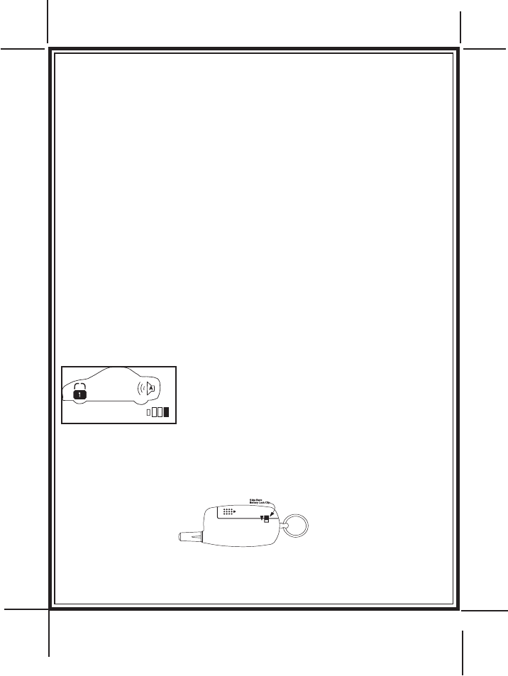
REPLACING THE BATTERY:
You will notice a decrease in transmitter range as the battery condition
deteriorates. There is also a low battery indicator
that indicate no bars in the LCD panel, as shown
left, when the battery begins to fail. Transmitter
battery replacement is recommended at least every
6 to 8 months, depending upon how frequently the
transmitter is used.
To replace the transmitter battery:
1. Slide back the lock tab on the back side of the transmitter case in the
direction shown.
5
128-6799D
6 of 8
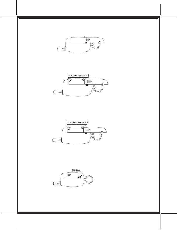
2. Slide back the battery case cover in the direction shown.
3. Remove the discharged battery, making note of the location of the + and -
contacts shown, and replace with a new type alkaline 1.5 volt AAA Battery.
4. Making note of the location of the (+) and (-) contacts, insert a new AAA
battery alkaline 1.5 volt.
5. Replace battery cover being certain to close the battery case lock clip to
prevent accidental opening.
6
128-6799D
7 of 8
Attention: Transmitter Ordering Department
Important: To help us expedite your order, please print all of the information
legibly and mail this form and your payment according to the instructions below.
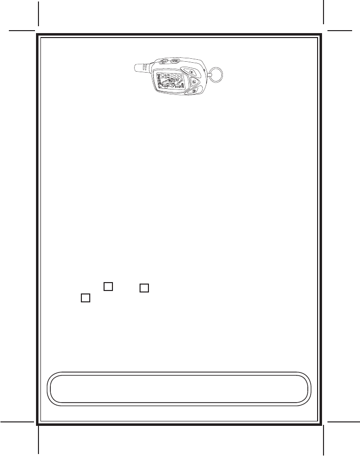
Be certain to specify MODEL NUMBER found on back of your transceiver
___________
1) Name:___________________________________________
2) Address:_________________________________________
3) City:________________State:________Zip Code:__________
4 Telephone Number:( )_____________________
5) Total Number Of Transmitters Required:_______
Cost Per Transmitter is: $85.00
Multiply By Number Of Transmitters X
6) Enter Total Amount Enclosed _______
(New York State Residents must include the appropriate sales tax)
7) Method of Payment:
Mastercard Visa Check or Money Order (do not send cash)
Make Checks Payable To Audiovox Corporation
Credit Card Number:___________________________________
Credit Card Expiration Date: ____/___/____
8) Mail this form along with your payment to:
Transmitter Ordering Department
Audiovox Corporation 150 Marcus Blvd., Hauppauge N.Y. 11788
Credit card purchasers can order additional or replacement trans-
mitters by phone. Simply dial 1 - 800 - 645 - 4994, and follow the
instructions from the operator interface
7
ORDER FORM FOR TRANSCEIVERS
5BCR/5BCR03/5BCR05/5BCR07

128-6799D
8 of 8
8
128-6799D
© 2016 Voxx Electronics Corp., 150 Marcus Blvd., Hauppauge, NY 11788
FCC COMPLIANCE
is device complies with part 15 of the FCC Rules. Operation is subject to the following two conditions:
(1) is device may not cause harmful interference, and
(2) this device must accept any interference received, including interference that may cause undesired operation.
is equipment has been tested and found to comply with the limits for a Class B digital device, pursuant to part
15 of the FCC Rules. ese limits are designed to provide reasonable protection against harmful interference in a
residential installation. is equipment generates, uses and can radiate radio frequency energy and, if not installed
and used in accordance with the instructions, may cause harmful interference to radio communications. However,
there is no guarantee that interference will not occur in a particular installation. If this equipment does cause
harmful interference to radio or television reception, which can be determined by turning the equipment o and
on, the user is encouraged to try to correct the interference by one or more of the following measures:
—Reorient or relocate the receiving antenna.
—Increase the separation between the equipment and receiver.
—Connect the equipment into an outlet on a circuit dierent from that to which the receiver is connected.
—Consult the dealer or an experienced radio/TV technician for help.
Warning!
Changes or modications made to this equipment not expressly approved by the part responsible for compliance
could void the use’s authority to operate the equipment
NOTE: e manufacturer is not responsible for any radio or TV interference caused by unauthorized modica-
tions to this
equipment. Such modications could void the user’s authority to operate the equipment.