User Manual
Status Lights
Valet Switch
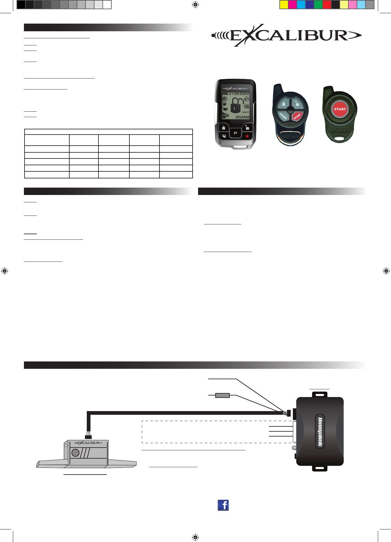
RF-50-EDP / RF-30-EDP / RF-10-EDP
Range Extender / OEM Upgrade Kit
Installation Guide
IS_RF-X0-EDP 10/19/2012
Feature Programming: Ignition on, off, press valet 5 times
# Feature Lock Button or
Brake Pedal x 1
Unlock button or
Brake Pedal x 2
Trunk button or
Brake Pedal x 3
”START” button or
Brake Pedal x 4
1 Ignition Lock/Unlock On Lock only Unlock only Off
2 Last Door Locking On Off
3 Automatic Relocking On Off Enhanced
4 Unlock w/ Trunk Release On Off
5 Remote Start Activation 1 press 2 presses 3 presses 4 presses
Step 1 Turn the ignition key “ON”, then “OFF”
Step 2 Within 5 seconds of step 1, press the valet switch 5 times to access features
~ The built in beeper will sound and the status light will turn on.
Step 3 Within 10 seconds of step 2, press the valet switch the number of times cor-
responding with the desired feature’s number.
~ The built in beeper will chirp equal to the selected feature.
Step 4 for RF-50-EDP & RF-30-EDP Change the feature by pressing the transmitter
button that corresponds with the desired setting.
Step 4 for RF-10-EDP Turn the ignition key back “ON”, some brake circuits require
ignition power to operate. Change the feature by pressing the brake pedal the number of
times that corresponds with the desired setting.
~ The built in beeper will chirp equal to the selected setting.
Step 5 If you wish to change more features, repeat steps 3 & 4 at this time.
Step 6 To exit programming, turn the ignition key “ON” then “OFF”. Or, you can wait 10
seconds for programming mode to expire.
PROGRAMMING FEATURES
Programmable Features
Wiring Overview
Lock (-) Input - BROWN
Remote Start Activation (-) Input - RED/WHITE
Unlock (-) Input - PURPLE/YELLOW
Adding Omega-Carlink Directly To RS Firmware Kit
Connect the Carlink AUX outputs to these inputs and program the outputs for
“1 second pulse” in the installation details during activation/conguration.
Visit www.omegaweblink.com/rs for more info and current vehicle applications.
RF-X0-EDP
Omega Carlink
Input Trigger Wires {
5 AMP
Constant 12 v (+) Input - RED
(Not required if using a T-harness)
Chassis Ground (-) Input - BLACK
(Not required if using a T-harness)
Omegalink module
ashed with RS rmware
~ REQUIRED ~
Window module/antenna:
Mount to windshield for easy
access and visibility.
Programming Transmitters/Controllers
Step 1 Have all transmitters which are to operate the system at hand. Then, turn the
ignition “on”.
Step 3
2-way and 4-button controllers: Press the “lock” button on each transmitter one at
a time. When the rst controller is learned, all previous controllers are erased from
memory. The transmitter’s other three button’s functions will automatically be assigned
when the “lock” button is learned.
1-button controllers: Press the “start” button on each transmitter one at a time. When
the rst controller is learned, all previous controllers are erased from memory.
The antenna will beep once to conrm that each was learned.
NOTE: If a code is not received within a 10 second period, the learning process will
automatically terminate, as indicated by a long beep.
Step 2 Within 5 seconds of turning on the ignition, press the Valet Switch 5 times. The
beeper in the antenna will briey sound, conrming that for the next 10 seconds the
system is ready to learn a transmitter/controller code.
Installation Overview
1) Install the Omegalink RS module per the instructions provided with the chosen
rmware and test for proper operation.
2) Connect to the Omegalink RS module:
If using a T-harness - Connect one end of the ribbon harness to the 4 pin black
connector on the T-harness. The T-harness will supply power and ground to the
antenna module. The RED power and BLACK ground wires aren’t used so make
sure they are cut/capped to prevent a short circuit.
If NOT using a T-harness - Connect one end of the ribbon harness to the 4 pin black
connector on the RS module. Connect the RED wire to a constant +12 volt source
and connect the BLACK wire to a good chassis ground point free of paint, grease, or
dirt. This will provide power to the RF module and the Omegalink RS module.
3) Connect to the RF-X0-EDP antenna module:
Connect the other end of the 4 pin ribbon harness to the antenna module and test for
all primary functions.
4) Mount the antenna module:
Choose a mounting location high on the windshield for best operating range. Be sure
that the location will not obstruct the driver’s view and is easily reached to access the
valet switch. Route the ribbon harness up the A-pillar to your chosen location
avoiding sharp or moving objects in the vehicle. Clean the mounting surface and
attach the antenna module with the provided double-stick tape.
www.caralarm.com | www.omegaweblink.com | www.wiresheet.com | www.facebook.com/omegard | 800.554.4053

This device complies with FCC Rules Part
15 Operation is subject to the following
two conditions (1) This device may not
cause harmful interference and (2) this
device must accept any interference that
may be received, including interference
that may cause undesired operation.
NOTE:The manufacturer is not responsible
for any radio or TV interference caused
by unauthorized modifications to this
equipment. Such modifications could void
the user’s authority to operate the
equipment.
FCC ID:ELVNTRLF