User Manual

INSTALLATION GUIDE
AL-XX70-B
Choose a discreet mounting location for the module and locations
for any accessories (siren, sensors, interface module, etc.). Do not
mount the module yet (you might anger the install gods).
Identify vehicle connection points and plan harness routing from
your mounting location. Avoid any moving vehicle parts or parts that
generate heat. Also avoid any sharp metal edges. See wiring details
on pages 3-10.
Cut system wires to length, prep your harnesses, and make all wire
connections to the vehicle.
NOTE: DATA/MUX WIRES ARE SENSITIVE and MUST BE SPLICED DIRECTLY.
QUICK TAPS ARE NOT RECOMMENDED.
If you are using either of the system’s data ports for accessories
or modules using DBI protocol, connect these modules now and
congure them for DATA MODE.
Perform VEHICLE LEARN (see pages 9 and 12 for instructions).
This automatically matches the IGN/ACC/START outputs to the vehicle’s ignition switch,
auto-detects data protocols, chooses the best engine detection method, decides whether
neutral safety circuit is required, and allows you to quickly set engine and transmission
types. FASTER THAN PROGRAMMING!
Test the system for all functions.
Secure the module(s) and harnesses to the vehicle.
Reassemble the vehicle.
Test the system for all functions again (keep the install gods happy).
Quick Reference - Installation Overview
1
2
3
4
5
6
7
8
9
WIRE DIAGRAM: CENTER OF THIS BOOKLET
FEATURE CHART: INSIDE BACK COVER
REMOTE START & SECURITY PERFECTED

Table Of Contents
6 Pin Main Wire Harness ............................................................................................ 3
Red and Red/White Wires - Constant Power (+) Input ............................................. 3
Pink Wire - IGNITION/ACC/START (+) Input/Output ................................................ 3
Orange Wire - ACCESSORY/IGN/START (+) Input/Output ..................................... 4
Violet Wire - Start (+) Input/Output ........................................................................... 4
Pink/White Wire - IGNITION/ACC/START (+) Input/Output ..................................... 4
18 Pin Secondary Wire Harness ................................................................................ 4
Black Wire - System Ground (-) Input ...................................................................... 4
Orange Wire - Starter Interrupt (-) Output & Relay ................................................... 4
Brown/Red Wire - Brake Pedal (+) Input .................................................................. 4
Black/White Wire - Neutral Safety (-) Input .............................................................. 4
Violet/White Wire - Tach Signal Input ....................................................................... 5
Brown Wire - Siren (+) Output .................................................................................. 5
White Wire - Flashing Light (+) Output ..................................................................... 5
White/Black Wire - Flashing Light (-) Output ............................................................ 5
Gray Wire - Hood Trigger (-) Input ............................................................................ 5
Green Wire - Door Trigger (-) Input .......................................................................... 5
Violet Wire - Door Trigger (+) Input .......................................................................... 5
Red/White Wire - Trunk Release / 2nd Channel (-) Output ...................................... 6
Black/Red Wire - Light Relay Pin 87 (+/-) Input ........................................................ 6
Green/Violet Wire - Light Relay Pin 30 Output ......................................................... 6
White/Red Wire - Light Relay Pin 87a (+/-) Input ..................................................... 6
Violet/Black Wire - Horn Relay Pin 87 (+/-) Input ..................................................... 6
Blue/Black Wire - Horn Relay Pin 30 Output ............................................................ 6
Brown/Black Wire - Horn Relay Pin 87a (+/-) Input .................................................. 6
4 Pin Secondary Wire Harness .................................................................................. 7
Pink Wire - 3rd Channel (-) Output ........................................................................... 7
White/Blue Wire - Remote Start Activation (-) Input ................................................. 7
Lt. Green/Red Wire - OEM Alarm Arm / CH4 (-) Output ........................................... 7
Lt. Green/Black Wire - OEM Alarm Disarm / CH5 (-) Output .................................... 7
3 Pin Satellite Relay Port (RED) ................................................................................ 7
Wiring Overview Diagram .......................................................................................... 8
3 Pin Satellite Relay Port (BLUE) ............................................................................ 10
4 Pin Door Lock/Unlock Port (RED) ........................................................................ 10
2 Pin Backup Battery Port (WHITE) ........................................................................ 10
Green Data Port .........................................................................................................11
Black Data/Programming Port..................................................................................11
BLADE Cartridge Port ...............................................................................................11
Dual Zone Sensor Ports (WHITE) .............................................................................11
Window Mount Antenna Module ............................................................................. 12
3D Motion Sensor ..................................................................................................... 12
Status Light ............................................................................................................... 12
Valet / Programming Button .................................................................................... 12
Vehicle Learn ............................................................................................................ 12
Tach Programming ................................................................................................... 13
Programming Transmitters...................................................................................... 13
Programmable Features .......................................................................................... 14

Installation Considerations
BEFORE STARTING THE INSTALLATION, READ THIS ENTIRE MANUAL
TO FAMILIARIZE YOURSELF WITH ANY INSTALL REQUIREMENTS
• BE SURE TO VERIFY EACH CIRCUIT WITH A DIGITAL MULTIMETER
• IDENTIFY WHICH CIRCUITS ARE REQUIRED FOR THE VEHICLE IN
QUESTION
• MOUNT ANY SYSTEM COMPONENTS & ROUTE WIRING AWAY
FROM MOVING PARTS OR PARTS OF THE VEHICLE THAT
GENERATE EXCESSIVE HEAT
• TAPE OFF OR REMOVE ANY UNUSED WIRING TO PREVENT
POSSIBLE SHORT CIRCUITS
• ONLY ACTIVATE THE REMOTE START FUNCTION IN A WELL
VENTILATED ENVIRONMENT
• AFFIX THE UNDERHOOD WARNING STICKER
• AVOID ANY AIRBAG CIRCUITS, USUALLY INDICATED BY A YELLOW
SLEEVE OR JACKET AROUND THE WIRING
6 Pin Main Wire Harness
RED AND RED/WHITE WIRES - CONSTANT POWER (+) INPUT
Most of the main wiring harness connections are high amperage circuits so it is recommended
to direct splice, solder, & adequately insulate each connection. Many of these connections are
made at the vehicle’s ignition switch so be sure to properly route the harness away from anything
that could compromise the wire insulation. The goal is to mimic the ignition switch. Keep this in
mind when deciding which ignition & accessory circuits to power.
NOTE: A low current harness for newer vehicles is available. It has 18 gauge, 100% copper
wires and the RED & RED/WHITE wires are fused at 10A each. Order P/N: H-RS6BLC
REQUIRED. These wires provide the constant positive 12v power supply for the system’s
operation. CONNECTION: Connect these to a constant +12 volt supply with sufcient amperage
for remote starting. The +12v power supply to the ignition switch is ideal. Some vehicle’s have
low amperage ignition switches in which case you would need to nd a power supply at a fuse
block or at the vehicle’s battery. Be sure these wires are fused within 6 inches of the connection
to the vehicle. The two 30AMP fuses in the harness are to protect the system module, NOT THE
VEHICLE. Their use is REQUIRED. It is ideal to have a separate supply for each wire but, if the
chosen supply is sufcient enough, you can combine the RED and RED/WHITE wires at the same
point.
PINK WIRE - IGNITION/ACC/START (+) INPUT/OUTPUT
REQUIRED. This connection is required & is critical to the operation of the system. It is an
“IGNITION ON” input when the ignition key is turned on. By default, it is the primary ignition output
for remote start operation. It turns on when remote start is activated & stays on during engine
cranking for the entire remote start sequence.
CONNECTION: Use any IGNITION, ACCESSORY, or secondary START circuit in the vehicle.
This wire is defaulted for IGNITION output though it may change through the VEHICLE LEARN
process (p.12) to match the connected vehicle circuit.
3

ORANGE WIRE - ACCESSORY/IGN/START (+) INPUT/OUTPUT
This circuit is designed to power additional IGNITION, ACCESSORY, or START circuits. By
default, it functions as an ACCESSORY output & turns on when remote start is activated (slightly
earlier than the ignition output), turns off during engine cranking, & turns back on for the remainder
of the remote start operation.
CONNECTION: Use any IGNITION, ACCESSORY, or secondary START circuit in the vehicle.
This wire is defaulted for ACCESSORY output though it may change through the VEHICLE
LEARN process (p.12) to match the connected vehicle circuit.
VIOLET WIRE - START (+) INPUT/OUTPUT
This output supplies positive voltage to the vehicle’s starter circuit. If using a starter interrupt
circuit for anti-grind, be sure this is connected on the starter side of the interrupt.
CONNECTION: The starter circuit is typically found at the ignition switch. The proper circuit will
show +12v only when the ignition key is in the START position.
6 Pin Main Wire Harness (cont’d)
PINK/WHITE WIRE - IGNITION/ACC/START (+) INPUT/OUTPUT
This circuit is designed to power additional IGNITION, ACCESSORY, or START circuits. By
default, it functions as an IGNITION output. It turns on when remote start is activated, stays on
during engine cranking, & for the entire remote start operation.
CONNECTION: Use any IGNITION, ACCESSORY, or secondary START circuit in the vehicle.
This wire is defaulted for IGNITION output though it may change through the VEHICLE LEARN
process (p.12) to match the connected vehicle circuit.
18 Pin Secondary Wire Harness
BLACK WIRE - SYSTEM GROUND (-) INPUT
REQUIRED. This input provides negative ground for all system operations.
CONNECTION: Using a properly sized ring terminal, connect this wire to the vehicle’s chassis.
Using an existing bolt is preferred but make sure that the connection point is clean & free of dirt,
grease, or paint. Bright shiny metal at the connection point is desired.
ORANGE WIRE - STARTER INTERRUPT (-) OUTPUT & RELAY
This provides 500mA negative ground while the alarm is armed for starter kill and/or during
remote start for anti-grind operation. The operation is selectable with installer feature #16.
CONNECTION: This wire is connected to the orange input wire on the optional start interrupt relay
socket. Then, locate the vehicle’s (+) starter wire at the ignition switch & cut it. Connect the starter
interrupt relay’s RED wire to the ignition switch side of the cut starter wire. Connect the starter
interrupt relay’s WHITE wire to the starter side of the cut starter wire.
BROWN/RED WIRE - BRAKE PEDAL (+) INPUT
REQUIRED. This input is a critical safety circuit which disables the remote start operation
whenever the brake pedal is pressed.
CONNECTION: Connect this to the brake switch wire that shows +12 volts when the brake pedal
is pressed. The vehicle’s ignition may need to be turned on during testing.
BLACK/WHITE WIRE - NEUTRAL SAFETY (-) INPUT
This is a safety circuit which allows remote start operation whenever the gear selector is in park
or neutral (automatic transmission), or when the parking brake is applied (manual transmission).
CONNECTION (Automatic Transmission): Connect this to the neutral safety switch wire that
shows (-) ground when the gear selector is in the park & neutral positions.
4

18 Pin Secondary Wire Harness (cont’d)
CONNECTION (Manual Transmission): When installer feature #11 is ON, connect this to the
parking brake switch wire that shows (-) ground when the parking brake is engaged.
VIOLET/WHITE WIRE - TACH SIGNAL INPUT
This input monitors the engine’s RPM signal. To use the tach wire, perform VEHICLE LEARN
(p.12) to auto-program. Otherwise, you must change installer feature #3 to the tach wire setting &
perform tach learn (p.13).
CONNECTION: This can be connected to any signal wire for an ignition coil, fuel injector, or the
signal to the tachometer in the dash. Use a digital multimeter set for AC volts to test. The appropri-
ate wire will read between 0.5-6 volts AC & will increase as the engine RPM increases.
BROWN WIRE - SIREN (+) OUTPUT
This output provides a 1 amp positive output to operate the included siren.
CONNECTION: Safely route this wire to the chosen mounting location of the siren & connect it to
the siren’s red wire. Connect the siren’s black wire to chassis ground.
WHITE WIRE - FLASHING LIGHT (+) OUTPUT
This output provides a 10 amp positive output to ash the vehicle’s parking lights (typically).
If the vehicle has a low current negative light circuit, use the WHITE/BLACK wire instead. If the
vehicle requires a relay, you can use the built-in FLASHING LIGHT relay instead of adding one.
CONNECTION: Connect this wire to the vehicle’s circuit that shows +12 volts when the parking
lights are on. BE SURE NOT TO CONNECT TO THE DIMMER CIRCUIT WHICH WILL CHANGE
VOLTAGE AS YOU TURN THE DIMMER KNOB.
WHITE/BLACK WIRE - FLASHING LIGHT (-) OUTPUT
This output provides a 250mA negative output to ash the vehicle’s parking lights. If the vehicle
has a positive parking light circuit, use the WHITE wire instead. If the vehicle requires a relay, you
can use the built-in FLASHING LIGHT relay instead of adding one.
CONNECTION: Connect this wire to the vehicle’s negative parking light circuit. It will show ground
when the parking lights are on. BE SURE NOT TO CONNECT TO THE DIMMER CIRCUIT
WHICH WILL CHANGE RESISTANCE TO GROUND AS YOU TURN THE DIMMER KNOB.
GRAY WIRE - HOOD TRIGGER (-) INPUT
REQUIRED. This input is used to detect entry into the hood area of the vehicle. It is also a criti-
cal safety circuit that prevents remote start functions while the hood is opened.
CONNECTION: Connect this wire to the vehicle’s existing hood switch or light. It will show ground
when the hood is opened. You can also use the included pin switch & mount it to the radiator core
support.
GREEN WIRE - DOOR TRIGGER (-) INPUT
This input is used to detect entry into the vehicle via any door opening.
CONNECTION: Connect this wire to the vehicle’s existing domelight circuit or door pin circuit. The
circuit will show ground when any door is opened. If you are required to connect to each individual
door pin, diode isolation is required. Use one 1-2 amp diode for each door, facing the diode’s
cathode (stripe) towards the vehicle wiring.
VIOLET WIRE - DOOR TRIGGER (+) INPUT
This input is used to detect entry into the vehicle via any door opening.
CONNECTION: Connect this wire to the vehicle’s existing domelight circuit or door pin circuit.
The circuit will show +12 volts when any door is opened. If you are required to connect to each
individual door pin, diode isolation is required. Use one 1-2 amp diode for each door, facing the
diode’s cathode (stripe) towards the alarm module. 5

18 Pin Secondary Wire Harness (cont’d)
RED/WHITE WIRE - TRUNK RELEASE / 2ND CHANNEL (-) OUTPUT
This output provides a 250mA negative output when the trunk release/CH2 function is activated
by the controller. The output will remain as long as the controller button(s) is held.
CONNECTION: Connect this wire to the vehicle’s existing trunk release switch if it is a low current
negative circuit. If the circuit is a high current ground or a positive circuit, the use of a relay is
required. NOTE: The built-in horn relay circuit can be programmed for trunk release if not
being used otherwise.
BLACK/RED WIRE - LIGHT RELAY PIN 87 (+/-) INPUT
This circuit provides the constant feed input for the built-in 10 amp light relay. This relay can be
programmed via installer feature #5 for other functions.
CONNECTION: Connect this wire to constant power or chassis ground as needed.
GREEN/VIOLET WIRE - LIGHT RELAY PIN 30 OUTPUT
This circuit provides the output for the built-in 10 amp light relay. This relay can be programmed
via installer feature #5 for other functions.
CONNECTION: Connect this wire to the vehicle circuit chosen to be driven. By default, connect to
the vehicle’s parking light circuit.
WHITE/RED WIRE - LIGHT RELAY PIN 87A (+/-) INPUT
This circuit provides the input for the built-in 10 amp light relay. This input is typically only
used for polarity reversing circuits or circuits that must be broken to operate. This relay can be
programmed via installer feature #5 for other functions.
CONNECTION: Connect this wire to constant power or chassis ground as needed.
VIOLET/BLACK WIRE - HORN RELAY PIN 87 (+/-) INPUT
This circuit provides the constant feed input for the built-in 20 amp horn relay. This relay can be
programmed via installer feature #19 for other functions.
CONNECTION: Connect this wire to constant power or chassis ground as needed.
BLUE/BLACK WIRE - HORN RELAY PIN 30 OUTPUT
This circuit provides the output for the built-in 20 amp horn relay. This relay can be
programmed via installer feature #19 for other functions.
CONNECTION: Connect this wire to the vehicle circuit chosen to be driven. By default, connect to
the vehicle’s horn circuit.
BROWN/BLACK WIRE - HORN RELAY PIN 87A (+/-) INPUT
This circuit provides the input for the built-in 20 amp horn relay. This input is typically only
used for polarity reversing circuits or circuits that must be broken to operate. This relay can be
programmed via installer feature #19 for other functions.
CONNECTION: Connect this wire to constant power or chassis ground as needed.
6

4 Pin Secondary Wire Harness
PINK WIRE - 3RD CHANNEL (-) OUTPUT
This output provides a 250mA negative output when the CH3 function is activated by the
controller. The output will remain as long as the controller button is held.
CONNECTION: Connect this wire to any desired add-on accessory that can utilize a negative
activation input.
WHITE/BLUE WIRE - REMOTE START ACTIVATION (-) INPUT
This input will activate the system’s remote start function when it receives 3 negative pulses.
Repeating this during remote start will turn off the remote start. You can change this to 1, 2, or 4
pulse activation with installer feature #1.
CONNECTION: Connect to any device you desire to activate remote start. It can be connected
directly to doorlock motor wires for activation from OEM keyless entry if the wire rests at ground &
pulses positive. The return to ground is counted as 1 pulse. NO RELAY IS NEEDED.
LT. GREEN/RED WIRE - OEM ALARM ARM / CH4 (-) OUTPUT
This output provides a 250mA negative pulse before remote start & when the system’s alarm is
disarmed. It can be programmed for 5th channel output with installer feature #18.
CONNECTION: Connect this wire to the vehicle’s OEM alarm disarm circuit. Typically, it will show
ground when the door cylinder key is turned to the unlock position.
LT. GREEN/BLACK WIRE - OEM ALARM DISARM / CH5 (-) OUTPUT
This output provides a 250mA negative pulse when remote start is turned off & when the
system’s alarm is armed. It can be programmed for 4th channel output with installer feature #18
CONNECTION: Connect this wire to the vehicle’s OEM alarm arm circuit. Typically, it will show
ground when the door cylinder key is turned to the lock position.
3 Pin Satellite Relay Port (RED)
GREEN WIRE - START (-) OUTPUT
This output provides a 250mA negative pulse when the large VIOLET start wire is active.
CONNECTION: If a negative starter circuit is needed, connect this directly to the vehicle’s
negative starter circuit. Otherwise, use a relay (AU-7) to convert this to a high current circuit.
BLUE WIRE - IGNITION/ACC/START (-) OUTPUT
This provides a 250mA negative output when the large PINK ignition wire is active.
CONNECTION: If a negative circuit is needed, connect this directly to the vehicle’s negative
starter circuit. Otherwise, use a relay (AU-7) to convert this to a high current circuit.
RED WIRE - CONSTANT (+) OUTPUT
This output provides a 500mA positive output to drive the positive pin of added relay coils.
7
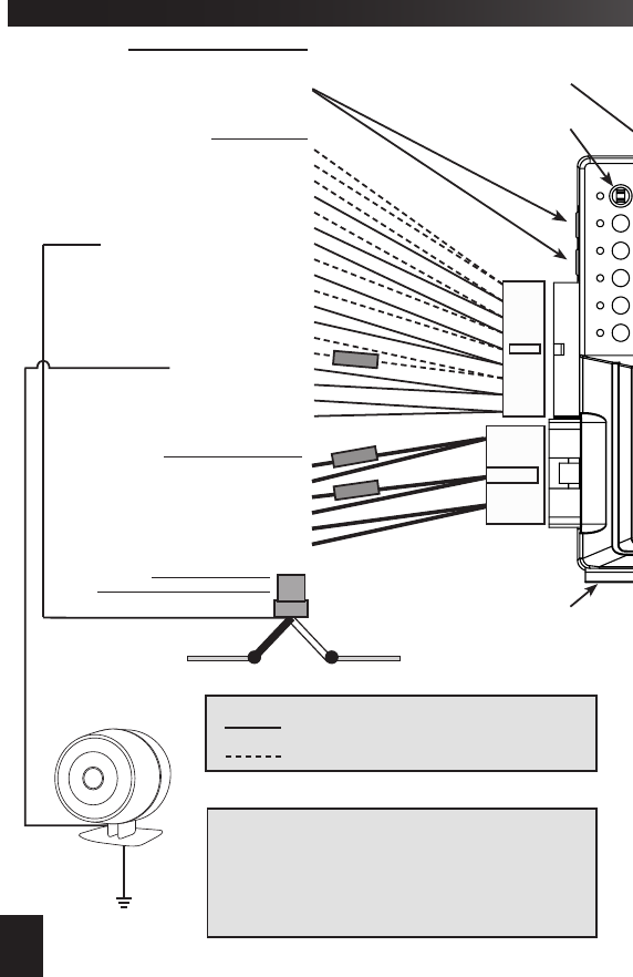
18 PIN HARNESS
Door Trigger (-) In - GREEN
Tach In - VIOLET/WHITE
Door Trigger (+) In - VIOLET
Light Relay Pin 87 (+/-) In - BLACK/RED
Trunk Release/CH2 (-) Out - RED/WHITE
Light Relay Pin 30 Out - GREEN/VIOLET3
Starter Interrupt (-) Out - ORANGE3
Flashing Light (-) Out - WHITE/BLACK
System Ground (-) In - BLACK
Brake (+) In - BROWN/RED
Neutral Safety (-) In - BLACK/WHITE
Light Relay Pin 87a (+/-) In - WHITE/RED
Hood Trigger (-) In - GRAY
Flashing Light (+) Out - WHITE
Siren (+) Out - BROWN
Horn Relay Pin 87a (+/-) In - BROWN/BLACK
Horn Relay Pin 30 Out - BLUE/BLACK3
Horn Relay Pin 87 (+/-) In - VIOLET/BLACK
6 PIN POWER HARNESS1
Constant 12v (+) In - RED/WHITE
Ignition #2 (+) In/Out - PINK/WHITE2
Constant 12v (+) In - RED
Start (+) In/Out - VIOLET
Ignition #1 (+) In/Out - PINK2
Accessory (+) In/Out - ORANGE2
10 AMP
30 AMP
30 AMP
SLIDE BRACKET FOR
BACKUP BATTERY & OTHER
ACCESSORIES
WIRE LEGEND
HARD WIRE CONNECTION REQUIRED
FUNCTION SUPPORTED VIA DATA PORTS
4 PIN ANALOG SENSOR PORTS
Constant 12v (+) Out - RED
Ground (-) Out - BLACK
Trigger (-) In - BLUE
Pre-warn (-) In - GREEN
ORANGE
RED
BLACK -
CHASSIS
GROUND
SIREN (OPTIONAL)
TEMPERATURE SENSOR
BLADE CARTRIDGE SLOT
(REMOVE DOOR)
NOTES
1. LOW CURRENT HARNESS P/N: H-RS6BLC Available
for vehicles with less than 20A ignition switches.
2. Learning output - see Vehicle Learn Procedure
3. Programmable output - see feature chart
4. Function matches PINK (6 PIN POWER HARNESS)
5. Function matches ORANGE (6 PIN POWER HARNESS)
OPTIONAL STARTER
INTERRUPT SOCKET & RELAY
To Starter
To Ignition Switch
WHITE
RED
Cut Starter
Wire
ORANGE
Wiring Overview Diagram
8
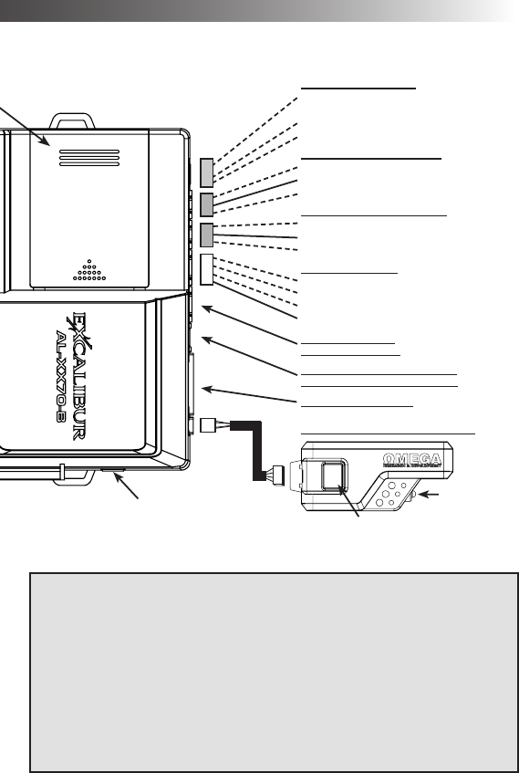
4 PIN DOOR LOCK PORT
Lock (-) Out - GREEN
Constant 12v (+) Out - PIN
Unlock #1 (-) Out - BLUE
Unlock #2 (-) Out - PINK
3 PIN SAT. RELAY PORT (RED)
Start (-) Out - GREEN
Constant 12v (+) Out - RED
Ignition (-) Out - BLUE4
BLADE HARNESS PORT
BLACK BLADE PROGRAMMING /
INTERFACE MODULE DATA PORT
GREEN INTERFACE
MODULE DATA PORT
BACKUP
BATTERY
PORT
WINDOW-MOUNT ANTENNA MODULE
Status Light
Valet / Programming
Button
4 PIN AUX HARNESS
OEM Disarm (-) Out - LT. GREEN/BLACK3
OEM Arm (-) Out - LT. GREEN/RED3
RS Activation (-) In - WHITE/BLUE
3rd Channel (-) Out - PINK
3 PIN SAT. RELAY PORT (BLUE)
Accessory (-) Out - GREEN5
Constant 12v (+) Out - RED
Status (-) Out - BLUE3
VEHICLE LEARN PROCEDURE
1. Connect any interface module(s) to the
data port(s) and set for data mode.
2. Turn the ignition key ON (do not start)
3. Activate remote start
System will chirp/ash lights to indicate engine
type (Default: 1x = Gasoline)
4. Press valet to change engine type:
1 chirp=Gasoline, 2 chirps =Diesel 15,
3 chirps=Diesel 20, 4 chirps=Diesel 30
5. Start the engine with the ignition key
6. Turn the ignition key OFF
System will chirp/ash lights equaling the # of
IGN/ACC/START circuits detected (Max: 4x)
7. Within 20 seconds of Step 6, Activate
remote start. Wait until engine is running
and LED is ashing slow.
8. OPTIONAL: To enable Manual
Transmission Reservation mode, release
and set parking brake again.
System should chirp/ash lights 1x.
9. TO SAVE SETTINGS: Shut down RS by
pressing the BRAKE pedal.
TO CANCEL/START OVER: Shut down
RS by remote or input wire.
~ See Page 12 For Full Details ~
Wiring Overview Diagram
Receiver part number: REC-1N4
Transceiver (2-way) part number: REC-2N4-3D, REC-2N9-3D

3 Pin Satellite Relay Port (BLUE)
GREEN WIRE - ACCESSORY/IGN/START (-) OUTPUT
This provides a 250mA negative output when the large ORANGE wire is active.
CONNECTION: Connect this directly to the vehicle’s low current negative ACCESSORY/IGN/
START circuit. Otherwise, use a relay (AU-7) to convert this to a high current circuit.
BLUE WIRE - STATUS (-) OUTPUT
This provides a 250mA negative output slightly before & during the primary ignition output. This
output is programmable. See installer feature #6 for other options.
CONNECTION: This is typically used to activate immobilizer bypass modules. Connect it directly
to the module’s activation input.
RED WIRE - CONSTANT (+) OUTPUT
This output provides a 500mA positive output to drive the positive pin of added relay coils.
4 Pin Door Lock/Unlock Port (RED)
GREEN WIRE - LOCK (-) OUTPUT
This provides a 0.8 second 250mA negative pulse for any locking operations. The pulse timing
is programmable by installer feature #8.
CONNECTION: Connect this directly to the vehicle’s lock circuit if a negative pulse is required.
Otherwise, a doorlock interface and/or relays are required to convert the output.
BLUE WIRE - UNLOCK #1 (-) OUTPUT
EMPTY PIN - CONSTANT (+) OUTPUT
This output provides a 500mA positive output to drive the positive pin of added relay coils.
This provides a 0.8 second 250mA negative pulse for any unlocking operations. The pulse tim-
ing is programmable by installer feature #8.
CONNECTION: Connect this directly to the vehicle’s “all door” unlock circuit if a negative pulse is
required. Otherwise, a doorlock interface and/or relays are required to convert the output. If you
are connecting driver’s priority unlocking, connect this only to the driver’s door unlock circuit.
PINK WIRE - UNLOCK #2 (-) OUTPUT
This provides a 0.8 second 250mA negative pulse for any unlocking operations. The pulse
timing is programmable by installer feature #8. This 2nd output is utilized only when you are
conguring the system for driver’s priority unlock.
CONNECTION: Connect this directly to the vehicle’s “all door” unlock circuit if a negative pulse is
required. Otherwise, a doorlock interface and/or relays are required to convert the output.
2 Pin Backup Battery Port (WHITE)
This system includes a bracket & harness for utilizing the backup battery option. Thanks to its
innovative design, it only requires a standard 9 volt battery. Insert the battery into the supplied
bracket & mount the battery pack on the slide bracket. Then, connect the harness to the battery &
module. When running on backup battery power, the system will only maintain the start interrupt,
siren, door trigger, & hood trigger functions to ensure maximum battery life.
NOTE: There is no dedicated harness included. Use the RED 3-pin harness for this port.
10

Green Data Port
This port provides a direct digital interface for any interface module, or other accessories,
using either the DBI protocol or iDatalink protocol. It eliminates the need for several wire-to-wire
connections. Refer to the wire diagram overview on page 8 to see which circuits are supported
by this port & compare them to the data functions available from the interface module. This port is
capable of using the D2D/DBI (Trilogix/Directed) protocol & iDataLink protocol. THIS PORT WILL
AUTO SELECT THE PROTOCOL DURING VEHICLE LEARN. MAKE SURE ANY CONNECTED
DEVICE IS PROPERLY CONNECTED & PROGRAMMED BEFORE HAND. The protocol is
manually selectable with installer feature #12. This port operates independently from the black
data port described below. BOTH THE GREEN & BLACK PORT CAN BE USED SIMULTANE-
OUSLY FOR PLUG-IN ACCESSORIES.
Black Data/Programming Port
This port operates exactly like the Green port & adds programming capability. THIS PORT
WILL AUTO SELECT THE PROTOCOL DURING VEHICLE LEARN. MAKE SURE ANY CON-
NECTED DEVICE IS PROPERLY CONNECTED & PROGRAMMED BEFORE HAND.
BLADE OPERATIONS: This port is also used to update the rmware for any BLADE cartridge
used instead of a standard interface module. When connected to the OmegaLink OL-LOADER,
this port can also be used to congure all programmable features as well as update the entire
system’s rmware. NOTE: Installing a BLADE forces this port to iDatalink protocol.
When utilizing an OmegaLink BLADE module, this 20 pin connector is used for the harness
that is included with the BLADE module. This allows you to connect directly to the vehicle’s data
bus & other required circuits for the interface.
BLADE Cartridge Port
On the top of the main module, there is a slide door. This door is removed & replaced with any
OmegaLink BLADE cartridge being used. The port is keyed so the cartridge will only insert one
way. Do not use excessive force to install the BLADE, it should snap in with light to moderate
pressure. Also, refer to the install guide for the BLADE rmware being used, for further informa-
tion & details. When this system detects a BLADE module, the data port protocol will automatic
switch to the iDatalink protocol. For more info on BLADE modules, visit www.omegaweblink.com.
There are notches in the corners of the port to safely eject the cartridge when needed.
Dual Zone Sensor Ports (WHITE)
This system is equipped with 2 white dual zone sensor ports. Any Omega single or dual zone
sensor will plug directly into these ports. A dual zone shock sensor is included with this system. If
more than 2 sensors are desired, you must diode isolate & splice into the GREEN & BLUE wires.
FOR “RS” MODELS: By default alarm functions are off w/ sensor detect enabled. If a pre-warn
trigger or full trigger is detected, it will automatically enable security functions.
BLADE CARTRIDGE PORT
BLADE HARNESS PORT
11

Status Light
The status light is built into the window mount antenna module. It is desirable for it to be visible
from as many angles around the vehicle as possible for maximum visual theft deterrence.
Valet / Programming Button
Vehicle Learn
The valet button is built into the window mount antenna module. It is used to put the system in
valet mode, program remotes, & program features.
Vehicle Learn is a procedure that allows you to quickly congure all vehicle dependant
features. It also serves as a diagnostic tool for your IGN/ACC/START output connections on the
main power harness. It’s much faster than programming, saving you valuable time, & helps you
discover critical mistakes.
VEHICLE LEARN WILL:
• Detect the function of the PINK, PINK/WHITE, and ORANGE wires to
automatically change the outputs to match the vehicle.
• Diagnose the PINK, PINK/WHITE, ORANGE, & VIOLET wire connections.
• Let you quickly choose engine type
• Auto-select Data-tach, tach wire, or tachless modes.
• Auto-select data port protocols
• Save tons of time in the bay!
BEFORE YOU BEGIN:
• Make all wire connections
• Connect any accessories/modules to the data ports.
If you are using an interface module/bypass kit, make sure it is in “DATA
MODE” and programmed to the vehicle.
• Set the parking brake if it is connected to the BLACK/WHITE wire.
This system is equipped with an outboard receiver or transceiver (2-way) module. It is designed
to be window mounted high on the windshield for optimal performance & range. It is best to mount
this module using the double sided stick pad included (be sure to clean glass before adhering).
Mount it high in the windshield trying to avoid metal parts of the vehicle as they can create “blind
spots” for the antenna. Also, metal based window tint can have an adverse affect on performance.
Since the system’s status light & valet are contained in this module, high visibility is also desired
for theft deterrence. Route the harness to the antenna module being sure to avoid sharp metal
objects that could compromise the harness jacket.
Some models are equipped with a motion sensor that provides added protection for remote
start by shutting down the engine if motion is detected during the START output. This is ideal
for manual transmission vehicles and eliminates the need for performing ‘manual transmission
reservation’ by the user. If the sensor is present, a “3D” logo will be on the antenna case.
Window Mount Antenna Module
3D Motion Sensor
12

Tach Programming
Step 1 Have all transmitters which are to operate the system at hand. Then, turn the ignition “on”.
Step 3 Press the “lock” button (press “start” button for RS-260-EDPB) on each remaining
transmitter one at a time. The system will chirp the horn once to conrm that each was learned.
The transmitter’s other button functions will automatically be assigned when the “lock” button
is learned. If a code is not received within a 10 second period, the learning process will
automatically terminate, as indicated by another horn honk.
Step 2 Within 5 seconds of turning on the ignition, press the Valet button 5 times. The horn will
briey sound, conrming that for the next 10 seconds the system is ready to learn a transmitter/
controller code. To enter a code, simply press & release the “lock” button. When the rst code is
learned all existing stored codes will be erased.
Standard Programming: Use this method to program additional or replacement transmitters.
Programming Transmitters
When utilizing the tach wire circuit for engine detection, the vehicle’s tach signal must be
learned. After making the tach wire connection, perform the following steps:
Step 1: Turn the ignition key “ON”.
Step 2: Within 5 seconds, press the brake pedal 5 times. (the siren/horn will chirp 5 times).
Step 3: Start the engine. The status light will turn on to indicate it has learned the current tach
signal. If it does not light, check your tach connection & start this procedure again.
Step 4: If the engine has a high idle at startup, it may be necessary to allow the idle to “settle”
to around 700 RPM. If needed, you can press the valet button 1 time to resample the
tach signal. The status light will ash off then back on once the signal has been
resampled.
Step 5: Turn the ignition key “OFF”.
Step 1: Turn the ignition key ON (do not start)
Step 2: Activate remote start by the remote, input activation wire, or smartphone control.
The system will chirp/ash lights to indicate engine type (Default: 1x = Gasoline).
Step 3: Press valet to change engine type, if needed:
The system will chirp/ash lights to conrm each selection.
1 chirp=Gasoline, 2 chirps=Diesel 15, 3 chirps=Diesel 20, 4 chirps=Diesel 30
Step 4: Start the engine with the ignition key
Step 5: Turn the ignition key OFF
The system will chirp/ash lights for the # of IGN/ACC/START circuits detected (Max: 4x).
EXAMPLE: If you connected the PINK, VIOLET, & ORANGE wires, the system should
chirp 3x. If it only chirps 2x, one connection has a problem and should be checked. Then
start over at Step 1 to retest.
Step 6: Within 20 seconds of Step 5, Activate remote start. Wait until engine is running and
LED is ashing slow.
- The system will poll both data ports for modules using the DBI protocol. If they do not
respond, it will automatically switch to iDatalink protocol.
- After the engine is running, the system will look for data tach & tach wire availability. If
detected, the system will switch to that method. If not, it will remain in tachless-hi.
Step 7: OPTIONAL: To enable Manual Transmission Reservation mode, release and set the
parking brake. (The BLACK/WHITE wire must be connected to the parking brake.)
System should chirp/ash lights 1x.
Step 8: TO SAVE SETTINGS: Shut down RS by pressing the BRAKE pedal.
This disables VEHICLE LEARN (installer feature #2).
TO CANCEL/START OVER: Shut down RS by remote or input wire.
Vehicle Learn Procedure
13

TO MANUALLY CHANGE FEATURES:
Step 1 Turn the ignition key “ON”, then “OFF”.
Step 2 Within 5 seconds of step 1, press the valet button 5 times to access user features (Press
10 times to access installer features).
~ The siren/horn will sound & the status light will ash.
Step 3 Within 10 seconds of step 2, press the valet button the number of times corresponding
with the desired feature’s number.
~ The siren/horn will chirp equal to the selected feature.
Step 4
4-button & 2-way MODELS: Change the feature by pressing the transmitter button that cor-
responds with the desired setting.
1-button MODELS: Change the feature by pressing the transmitter button OR brake pedal the
same number of times that corresponds with the desired setting (make all presses before hearing
any chirps). NOTE: some cars require the ignition to be on for the brake circuit to operate. In
this case, turn on the ignition before pressing the brake.
~ The siren/horn will chirp equal to the selected setting.
Step 5 If you wish to change more features, repeat steps 3 & 4 at this time.
Step 6 To exit programming, turn the ignition key “ON” then “OFF”. Or, it will exit automatically
after 10 seconds of no activity.
RESTORING FEATURE SETTINGS TO FACTORY DEFAULT:
Step 1 Enter Installer Feature programming (DO NOT SELECT ANY FEATURES).
Step 2
4-button & 2-way MODELS: Press LOCK + UNLOCK (or BRAKE x 5)
1-button MODELS: Press the START button 5 times (or BRAKE x 5)
~ The siren/horn will sound to indicate reset & exit programming
This device complies with FCC Rules part 15. Operation is subject to the follow-
ing two conditions, (1) This device may not cause harmful interference &, (2) This
device must accept any interference that may be received, including interference
that may cause undesired operation.
The manufacturer is not responsible for any radio or TV interference caused by
unauthorized modications to this equipment. Such modications could void the
user’s authority to operate the equipment.
A matrix of all programmable features & their options are on the next page. For detailed
information on each feature, please refer to the operation manual. Use the procedure below to
make any necessary changes.
NOTE: You can program features via your computer with Omega Weblink.
Visit www.omegaweblink.com for more information.
PROGRAMMING FEATURES
Programmable Features
14
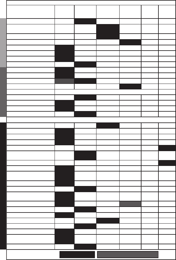
CONVENIENCESECURITYINSTALLER ONLY
User Feature Programming: Ignition on, off, press valet 5 times
# Feature Lock Button
(Brake 1x)
Unlock button
(Brake 2x)
Trunk button
(Brake 3x)
Start button
(Brake 4x)
Lock +
Unlock
(Brake 5x)
Trunk
+ Start
(Brake 6x)
1 Remote Start Run Time 3 min 10 min 15 min 20 min 30 min
2 Flashing Light Conrmations Unlock: ON
RS: ON
Unlock: ON
RS: Flash
Unlock: Flash
RS: ON
Unlock: Flash
RS: Flash
3 Conrmation Chirp Volume Low Med-Low Med-High High
4 BROWN Wire: Siren / Pulsed Horn Pulse LOW Pulse MED Pulse HI Steady Siren Random
5 Ignition Lock / Unlock Off Ign On = Lock Ign. Off = Unlock Lock + Unlock
6 Door Open Bypass for Feat. #5 On Off
7 Unlock w/ Trunk Release On Off
8 RS Activation (Remote) Start x 1 Start x 2 Start x 3 Start x 4
9 Last Door Arming Off On w/o Lock On w/ Lock
10 Automatic Rearming Off On w/o Lock On w/ Lock Enhanced
11 Conrmation Chirps Siren + Horn Siren Only Horn Only On Demand Off
12 Anti-Carjacking Ignition Door Ignition + Door Off
13 Override Code See operation guide for programming instructions. DEFAULT: 1,0
14 Ignition Override On Off
15 Alarm Trigger Duration 30 sec 60 sec 90 sec 120 sec
16 Arming Delay 3 sec 15 sec 30 sec 45 sec
17 Open Door Warning Upon Arming On Off
Installer Feature Programming: Ignition on, off, press valet 10 times
1 RS Activation (WHITE/BLUE wire) 1 Pulse 2 pulses 3 pulses 4 pulses
2 Vehicle Learn Enabled Disabled
3 Engine Detection Prog. Voltage Voltage Tach Wire Data-tach Crank Only
4 Gasoline or Diesel Engine Gasoline 15 sec Diesel 20 sec Diesel 30 sec Diesel
5 Light Relay Function Dome Light Start Ignition Accessory Status Light Flash
6 Blue Sat Port BLUE Wire Ignition Status 0.8 sec Defrost
Pulse
10 min Defrost
Pulse
Pulse After
Engine Off Horn
7 Crank Time 0.75 sec 1 sec 1.5 sec 2.25 sec 3 sec Average
8 Door Lock/Unlock Outputs 0.8 sec 3 sec Double Unlock Total Closure
9 Remote Start Lock Control Off Lock after Start Unlock before
Start
Unlock Before
& Lock After
Lock After
Engine Off
10 Turbo Timer Off 1 min 2 min 3 min
11 Manual Transmission Reservation On Off
12 Data Port Protocol Green: DBI
Black: DBI
Green: iData
Black: iData
Green: DBI
Black: iData
Green: iData
Black: DBI
13 Alarm Functions On Off Off-Unlock Only Sensor Detect
14 Pulse Ign. on Disarm On Off
15 Lock On Prewarn On Off
16 Starter Interrupt Alarm Only Anti-grind Only Alarm/Anti-Grind Automatic
17 Low Temp Crank Extender 0 ms 200 ms 300 ms 400 ms
18 Arm/Disarm or CH. 4/5 Arm/Disarm Arm/CH. 5 CH. 4/Disarm CH. 4/CH.5
19 Horn Relay Function Horn Ignition Trunk Release Pulse After
Start
20 Low Current Mode On Off
FEATURE SETTING KEY: Default Setting Default For “RS” Models When Different

IM_AL-XX70-B_8/1/2016
16