User Manual
Algovita™
Spinal Cord
Stimulation
System
Stimulator Models
2408 and 2412
For IPG
replacement
Implant Manual
for Stimulator
IPG implant.indb 1 3/3/14 8:46 AM
Algovita™ is a trademark of QIG Group, LLC
CoreGuard™ is a trademark of Greatbatch, Inc.
Refer to the Information for Prescribers Manual for indications, contraindications, warnings,
precautions, adverse events, and related information.
FCC Information (US Only)
e following is communications regulation information about the Algovita Implantable Pulse
Generator (IPG).
2408 and 2412 IPG FCC ID: 2ABU824082412
ese devices comply with part 15 of the FCC Rules. Operation is subject to the following two
conditions: (1) ese devices may not cause harmful interference, and (2) ese devices must
accept any interference received including interference that may cause undesired operation.
Important: Changes and modications to these products not authorized by Algostim, LLC could
void the FCC certication and negate your authority to operate these products.
IPG implant.indb 2 3/3/14 8:46 AM

Algovita Spinal Cord Stimulation System
Stimulator Model 2408 and 2412 Implant Manual 3
Contents
Explanation of Symbols Used on Packaging 5
Component Description 7
Package Contents 8
Component Sterilization 8
About this IPG Replacement Manual 8
Implant Procedure 8
Preparing for Surgery 8
Preoperative IPG Preparation 9
Explanting the IPG 13
Connecting the Leads or Extensions to the New IPG 13
Checking System Integrity 16
Implanting the New IPG 16
Completing the Implant Procedure 17
Patient Counseling Information 17
SCS System Implant: IPG Replacement 17
Registration Form and Temporary Patient ID Card 18
Returning Explanted Components 18
Algostim Customer Service 18
Specications 19
Wireless Information 20
Algovita SCS System Component Compatibility 21
IPG implant.indb 3 3/3/14 8:46 AM

4 Stimulator Model 2408 and 2412 Implant Manual
IPG implant.indb 4 3/3/14 8:46 AM
Algovita Spinal Cord Stimulation System
Implant Manual for Stimulator 5
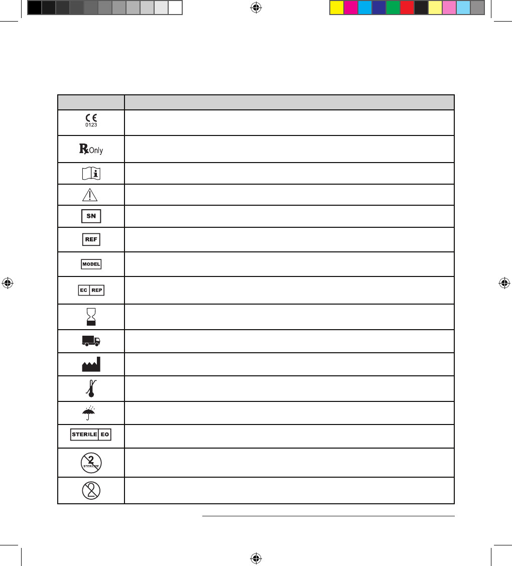
Explanation of Symbols Used on Packaging
Symbol Explanation
20XX
Conformité Européenne (European Conformity). is symbol means that the device
fully complies with European Directive AIMD 90/385/EEC.
Caution: Federal Law (USA) restricts this device to sale on or by the order of a physician.
Consult instructions for use
Caution
Serial number
Catalog number
Model number
Authorized representative in Europe
Use by date
Distributed by
Manufacturer
Temperature limit
Keep dry
Sterilized using ethylene oxide
Do not resterilize
Do not reuse
IPG implant.indb 5 3/3/14 8:46 AM
6 Implant Manual for Stimulator
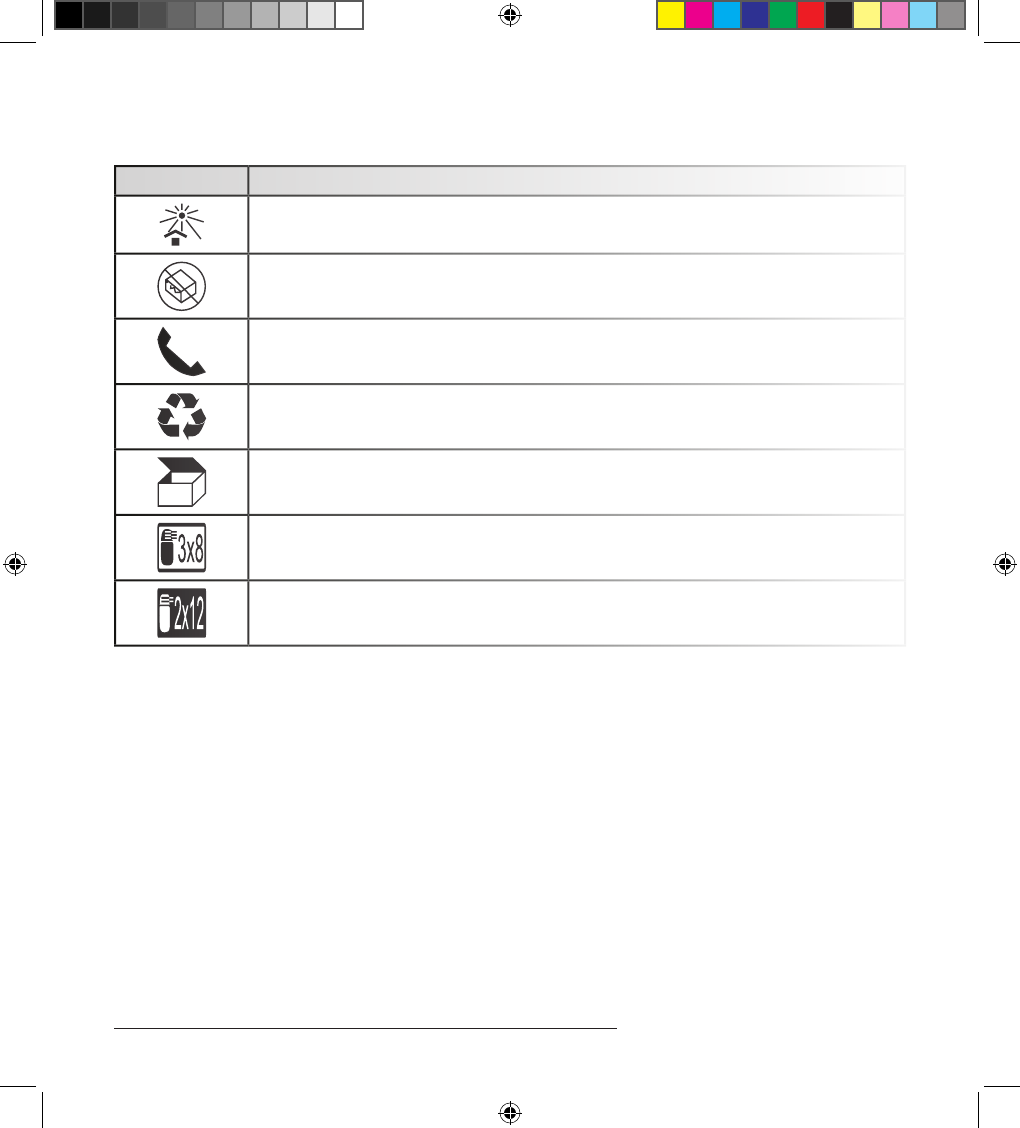
Explanation of Symbols Used on Packaging
Symbol Explanation
Keep away from sunlight
Do not use if package is damaged
Phone
Recycle
Contents
IPG: 3 connector ports with 8 channels each
IPG: 2 connector ports with 12 channels each
IPG implant.indb 6 3/3/14 8:46 AM
Algovita Spinal Cord Stimulation System
Implant Manual for Stimulator 7
Component Description
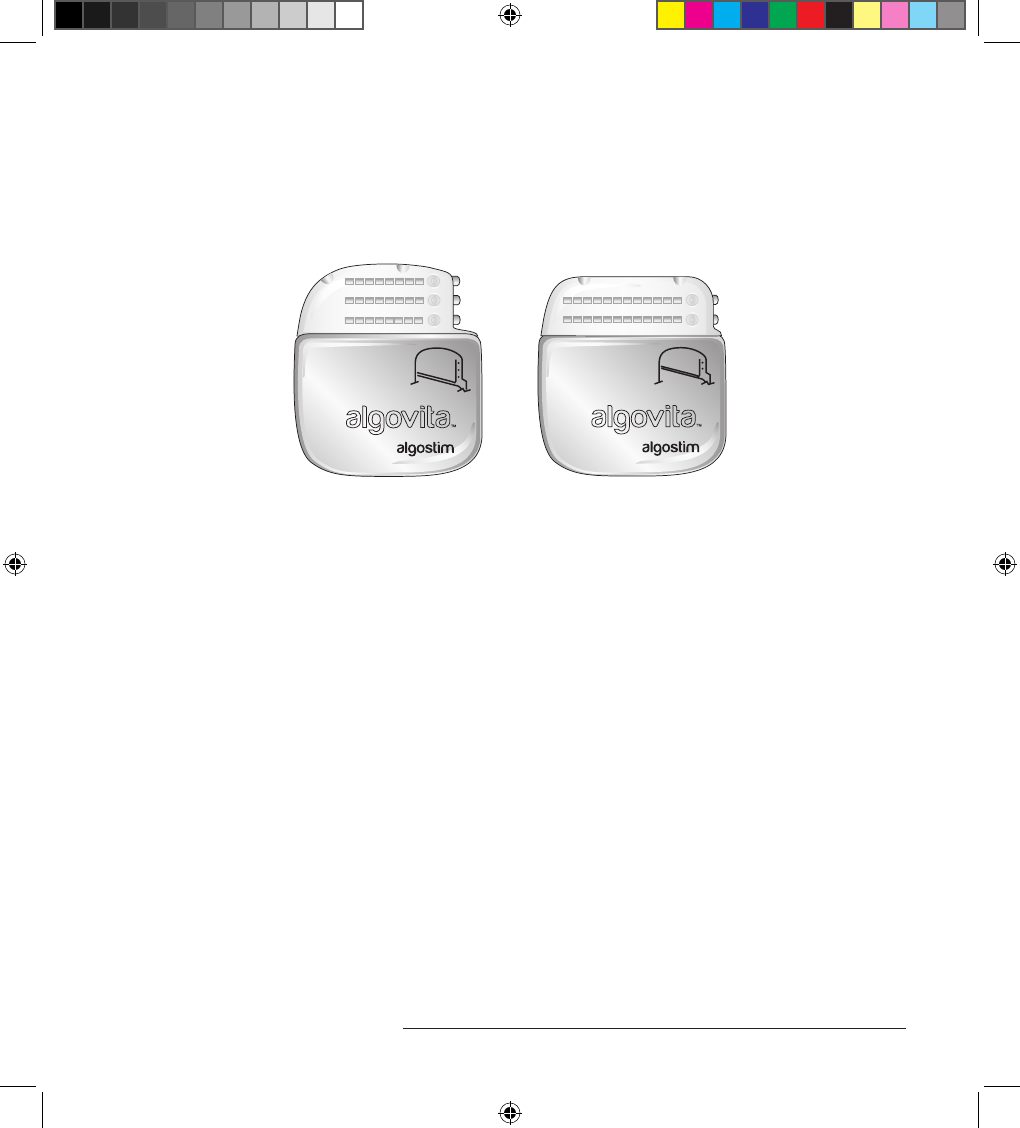
e Algovita™ Stimulator Model 2408 or 2412 (Figure 1) is part of the Algovita Spinal Cord
Stimulation (SCS) System, a rechargeable, 24-electrode, SCS system for the treatment of chronic
pain.
1
2
1
2
3
,LLC ,LLC
Figure 1. Algovita Stimulator Model 2408 and Model 2412
e Algovita Stimulator is the implantable pulse generator (IPG) for the Algovita SCS System. In
addition to the IPG, the implanted components of the SCS system consist of percutaneous leads or
paddle leads with optional extensions.
During the intraoperative test, an external pulse generator (EPG) is used in place of the IPG. e
clinician programs the IPG and the EPG using a Clinician Programmer. e patient adjusts the
system using either of 2 patient programmers.
Algovita IPGs are 24-channel rechargeable IPGs. Each channel allows the system 1 active electrode.
e channels are distributed over 2 or 3 connector ports, depending on the IPG model.
• Algovita Stimulator Model 2408 (3x8 channel)—ree connector ports accommodate 1 to 3
percutaneous leads, with each lead allowing up to 8 active electrodes.
• Algovita Stimulator Model 2412 (2x12 channel)—Two connector ports accommodate 1 or 2
percutaneous or paddle leads, with each lead allowing up to 12 active electrodes.
e IPG delivers stimulation using independent current distribution, a technology that allows
variable amounts of current to be delivered to each active electrode.
e IPG battery is a deep discharge recovery battery with CoreGuard™ technology. Even if the
patient allows the battery to completely discharge, the battery can be recharged with the Algovita
Programmer Charger.
IPG implant.indb 7 3/3/14 8:46 AM

8 Implant Manual for Stimulator
Package Contents
Package Contents
• Stimulator Model 2408 (3x8) or Model 2412 (2x12)
• Torque wrench
• Port plugs (3 for Model 2408, 2 for Model 2412)
• Product literature
• Temporary patient ID card
• Implant registration form and business reply envelope
Component Sterilization
e implantable and surgical accessory components were sterilized with ethylene oxide prior to
shipment. e SCS system sterile components are intended for single use only and must not be
resterilized.
Caution: Do not resterilize a system component or reimplant an explanted system component
because of risk of infection or malfunction.
About this IPG Replacement Manual
is manual provides the instructions for the replacement of an Algovita Stimulator Model 2408
or 2412. For complete instructions on implanting an IPG as part of a system implant, refer to the
system manual packaged in the lead kit.
Implant Procedure
Implanting clinicians should be thoroughly familiar with this manual and all other product
labeling.
Caution: Do not place the charging paddle on an unhealed wound. e charging paddle is not
sterile. Contact with an unhealed wound may result in an infection.
Preparing for Surgery
Before opening the sterile pack, verify the following on the sterile pack label:
• IPG—Model number and use-by date
IPG implant.indb 8 3/3/14 8:46 AM
Algovita Spinal Cord Stimulation System
Implant Manual for Stimulator 9
Preoperative IPG Preparation
Cautions:
» To allow the surgical wound to heal before another charge is needed, charge the IPG in its
shelf carton before implanting.
» To assure maximum IPG battery life, make sure the IPG and its packaging are at room
temperature before charging the IPG.
» Charging at temperatures above 35°C (95°F) can impair charging paddle operation.
» Do not implant the IPG if it has been dropped onto a hard surface.
» Use extreme care when handling system components prior to implantation. Excessive heat,
excessive traction, excessive bending, excessive twisting, or the use of sharp instruments
may damage a component, which may cause component failure.
Before implanting an IPG, verify that the IPG is fully charged, verify IPG function, and determine
the IPG implant site. A fully charged IPG allows the wound to heal before a recharge is needed.
Verify that the IPG is functioning by using the Clinician Programmer to read the IPG battery
charge level. (Refer to the Clinician Programming Manual for instructions on how to read the
battery charge level.)
To charge the IPG and verify that the IPG is functioning:
1. If the Programmer Charger needs charging, connect the power cord and AC power adapter to
the Programmer Charger, and plug the AC power adapter into a wall outlet.
Note: To determine if the Programmer Charger needs charging, see the Patient System
Manual.
2. Connect the charging paddle to the Programmer Charger.
3. Turn the Programmer Charger on by sliding and holding the power on/o button on the side
of the Programmer Charger.
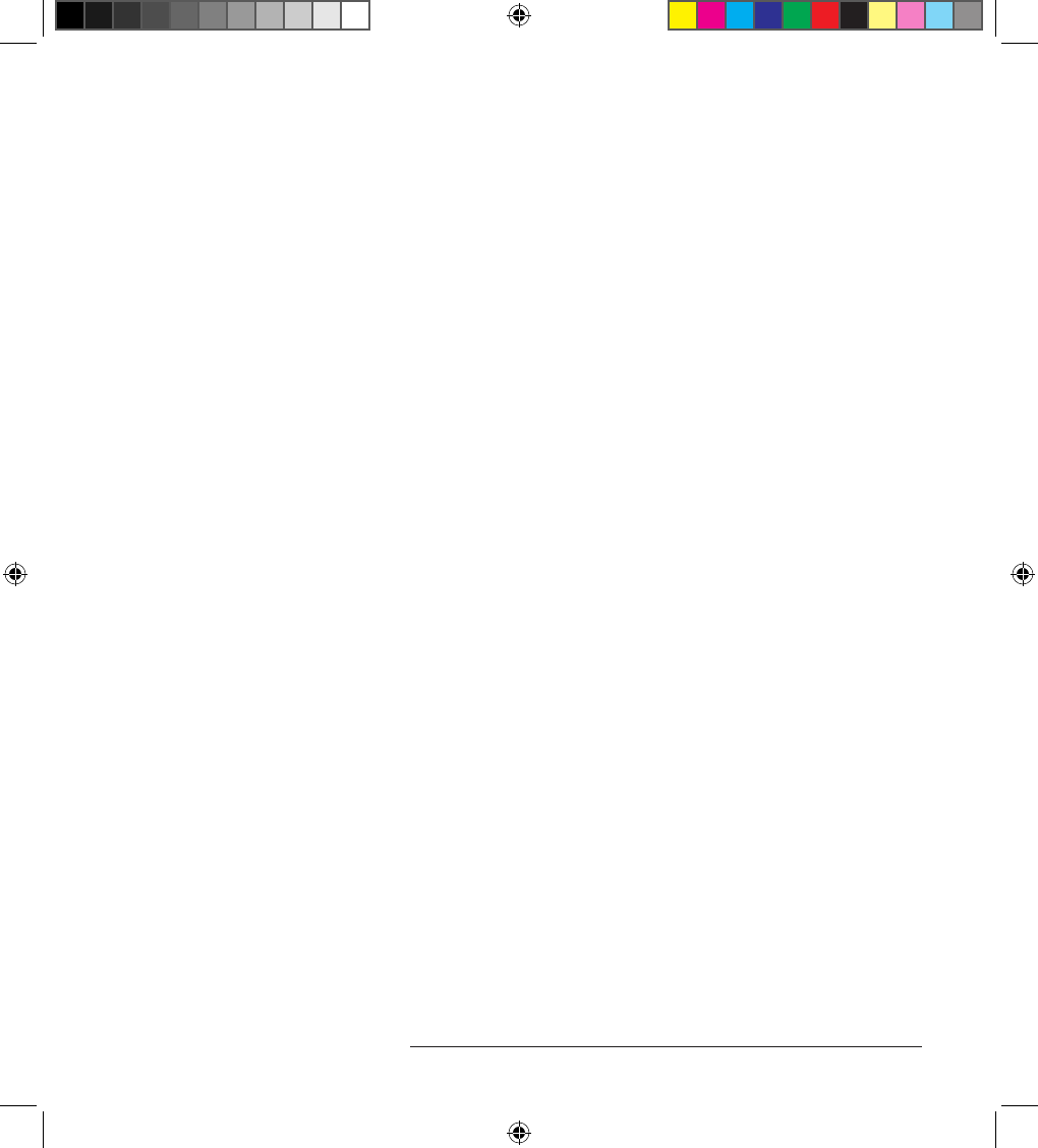
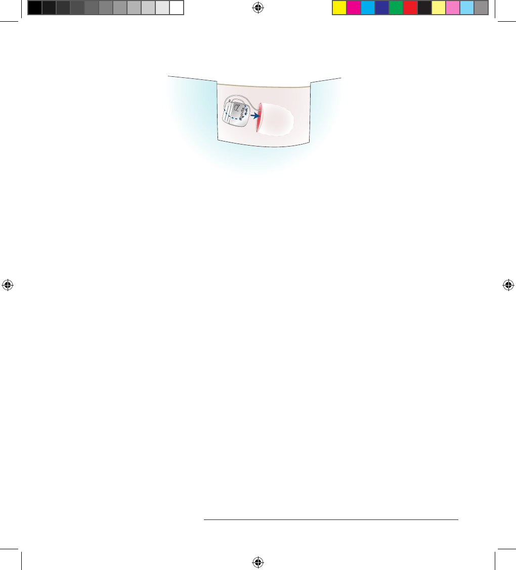
4. Li the ap on the top of the IPG shelf carton and place the charging paddle on the window
over the IPG (Figure 2).
IPG implant.indb 9 3/3/14 8:46 AM
10 Implant Manual for Stimulator
Implant Procedure
1 12
12 24
1
2
,LLC
Figure 2. Preoperatively check the IPG
IPG implant.indb 10 3/3/14 8:46 AM
Algovita Spinal Cord Stimulation System
Implant Manual for Stimulator 11
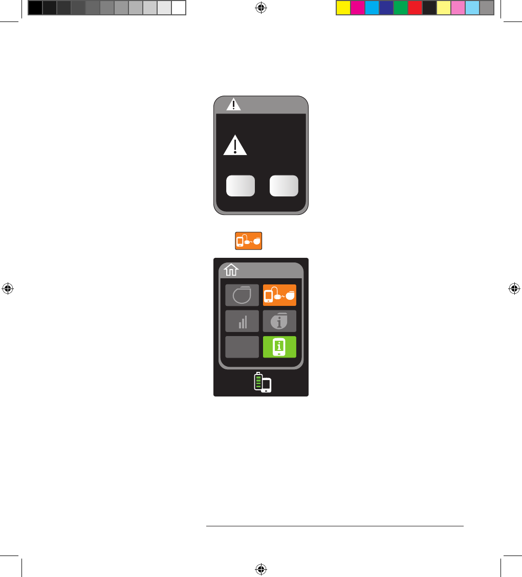
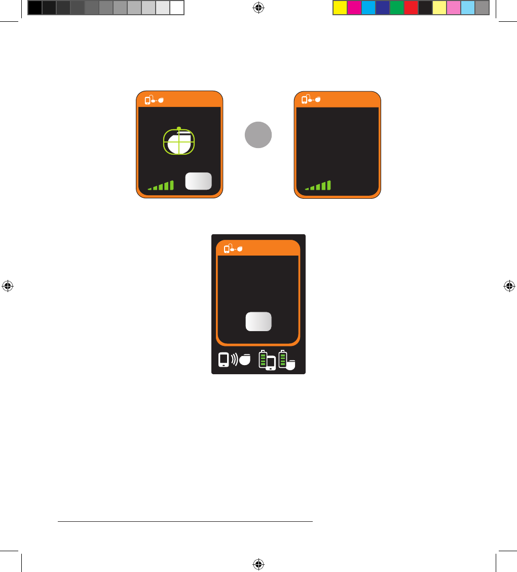
5. When the Notication screen appears, select Cancel (Figure 3).
Notification
Not able to
connect with IPG
Cancel Retry
Figure 3. Notication screen
6. When the Main screen appears, select (Figure 4).
P
Figure 4. Main screen
IPG implant.indb 11 3/3/14 8:46 AM
12 Implant Manual for Stimulator
Implant Procedure
7. While the IPG is charging, the Charge Status screen is displayed (Figure 5).
>
Charge Status
OK
Charge Status
Charging in
Progress
OK
Figure 5. Charging in progress.
8. When the Charge Status screen shows that charging is complete, select OK (Figure 6).
Charge Status
Charging complete
OK
Figure 6. IPG charging complete
IPG implant.indb 12 3/3/14 8:46 AM

Algovita Spinal Cord Stimulation System
Implant Manual for Stimulator 13
Explanting the IPG
1. Turn o the IPG.
2. Place the patient in a position that will allow access to the IPG.
3. Use standard sterile technique to prepare and drape the patient.
4. Administer prophylactic antibiotics according to an infection control protocol.
Caution: To help prevent infection, use prophylactic antibiotics. An infection may require the
removal of the entire SCS system.
5. Using standard surgical technique, open the IPG pocket.
6. Remove the IPG from the pocket.
7. Use the Algovita torque wrench to unscrew the setscrews.
8. Remove the leads or extensions from the IPG header.
9. Return the explanted IPG components to Algovita as instructed in the Returning Explanted
Components on page 18.
Connecting the Leads or Extensions to the New IPG
1. Prepare the lead or extension for connection to the new IPG.
a. Wipe the lead or extension contacts dry with sterile gauze.
Note: Wipe gloves dry before drying or cleaning components.
b. If the contacts came in contact with body uids or saline, thoroughly clean the contacts
with sterile deionized or sterile water, then dry them completely.
Caution: Before connecting a lead or extension to the IPG, wipe o any body uids and
dry the connections. Fluids in the connections may result in stimulation at the connection
site, intermittent stimulation, or loss of stimulation.
c. Inspect the lead or extension for any evidence of damage or corrosion. Explant and replace
any damaged or corroded component.
2. Fully insert each lead into the appropriate connector port.
Caution: Do not use saline or other ionic uids at connections. Ionic uids in the
connection may cause in a short circuit.
a. Grasp the lead or extension in the middle of the contacts.
IPG implant.indb 13 3/3/14 8:46 AM
14 Implant Manual for Stimulator
Implant Procedure
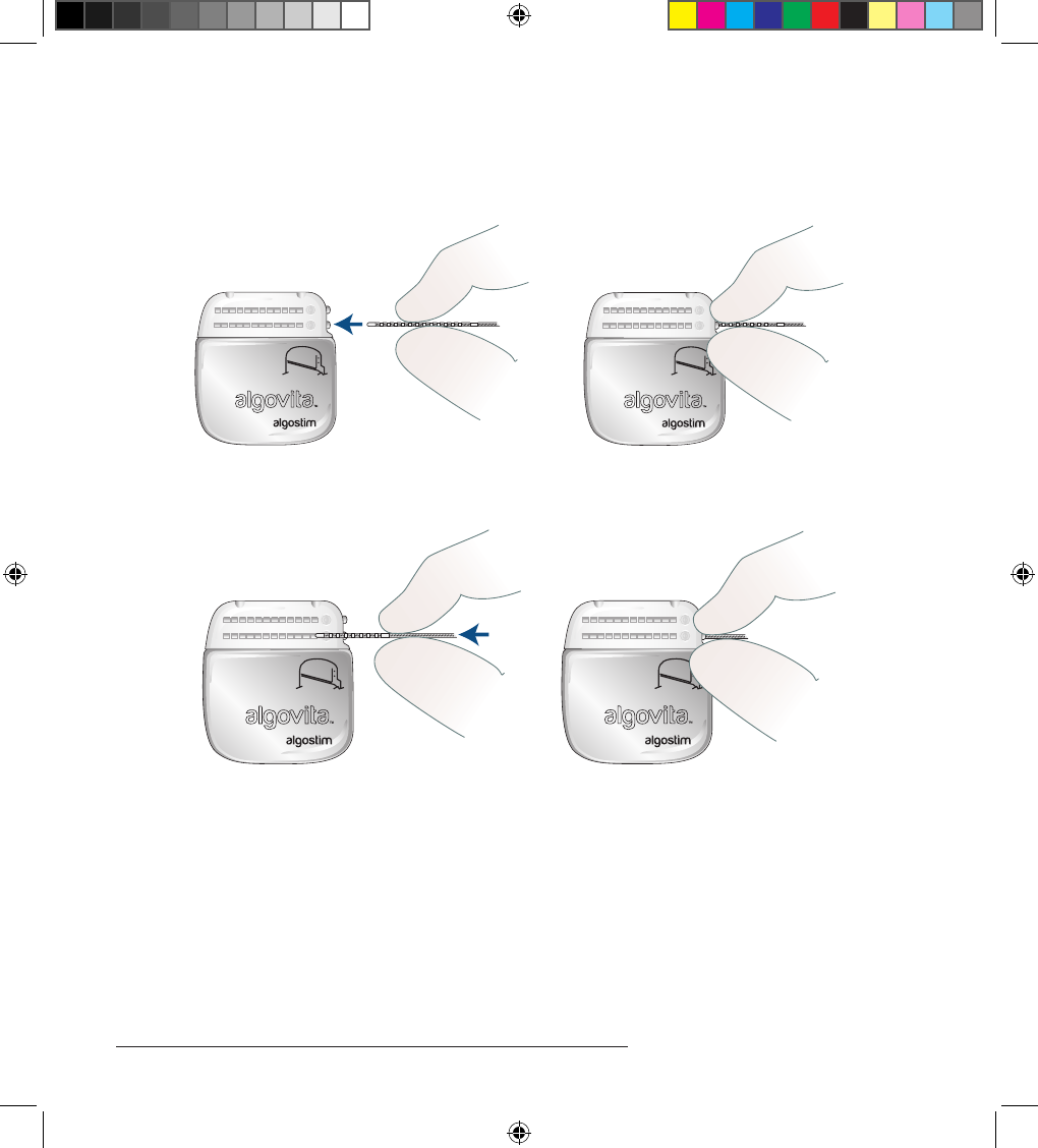
b. Slowly insert the lead or extension into the appropriate connector port (Figure 7), stopping
when the lead or extension begins to meet resistance or your ngers touch the connector
port.
1
2
,LLC
1
2
,LLC
Figure 7. Insert the lead or extension into the connector port.
c. Grasp the lead or extension near the setscrew ring (Figure 8).
1
2
,LLC
1
2
,LLC
Figure 8. Grasp near setscrew ring.
d. Using a steady force, continue inserting the lead or extension into the connector port.
e. When the lead is fully inserted, you will see the end of the lead move to the back of the
connector port and feel it stop against the back of the connector port. e setscrew ring
will be aligned with the setscrew.
f. Repeat the insertion steps for additional leads or extensions.
IPG implant.indb 14 3/3/14 8:46 AM
Algovita Spinal Cord Stimulation System
Implant Manual for Stimulator 15
3. Insert a port plug into any connector port not being used for this implant (Figure 9).
1
2
,LLC
Figure 9. Insert a port plug into any unused port.
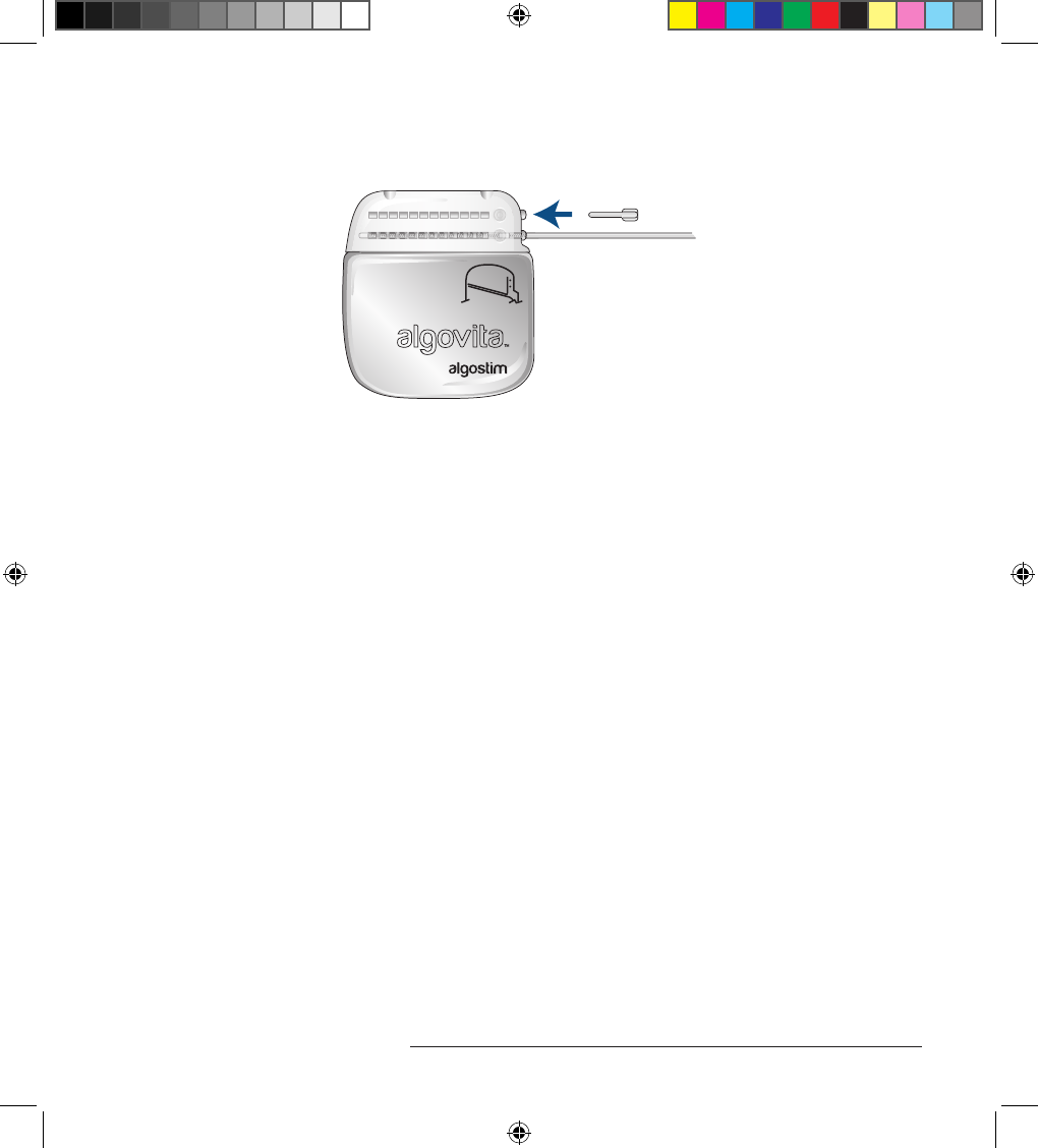
4. Using the torque wrench provided in the IPG package, tighten each lead, extension, and port
plug.
Cautions:
» Use only the torque wrench that is part of the Algovita SCS System. Using another
torque wrench may damage the lead, and may result in stimulation at the connection
site, intermittent stimulation, or loss of stimulation.
» e torque wrench is single use only. Do not resterilize the torque wrench because of
risk of infection or device malfunction.
a. Fully insert the torque wrench into the grommet in the IPG header until it stops in the
setscrew socket.
Caution: Make sure the torque wrench is fully inserted into the grommet before tightening
because the setscrew may be damaged, resulting in intermittent stimulation or loss of
stimulation.
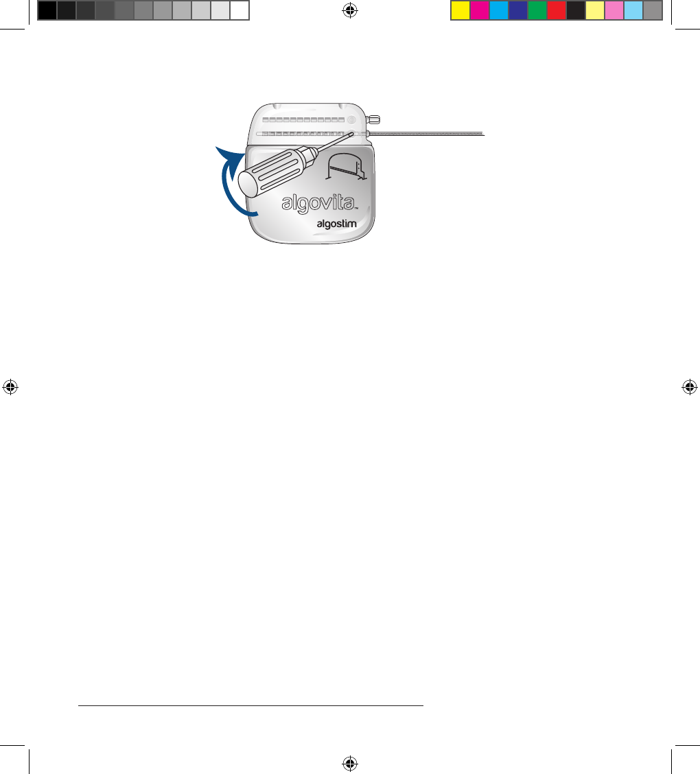
b. Turn the torque wrench clockwise until it clicks once (Figure 10). If you continue to turn,
the wrench will continue to click, but the additional turns do not tighten the setscrew
further.
IPG implant.indb 15 3/3/14 8:46 AM
16 Implant Manual for Stimulator
Implant Procedure
1
2
,LLC
Figure 10. Tightening the setscrews.
Checking System Integrity
1. To ensure the leads or extensions have been properly connected to the IPG and to rule out
a short or open circuit, use the Clinician Programmer to program the basic stimulation
parameters, check the battery charge level, and check the electrode impedances.
2. If the system integrity test results are not acceptable, check the connections made in
Connecting the Leads or Extensions to the New IPG on page 13.
Implanting the New IPG
1. Making sure of the following, place the IPG into the subcutaneous pocket (Figure 11):
» IPG is parallel to the skin and the Algovita logo is facing outward
» Lead or extension is loosely coiled behind the IPG with no sharp bends in the coils
» IPG is placed no deeper than 1.5 cm below the skin
Caution: Ensure that the IPG is placed deep enough to avoid dehiscence or erosion. Also
ensure that the IPG is placed no deeper than 1.5 cm (0.59 in) below the skin and is parallel
to the skin. If the IPG is too deep or is not parallel to the skin, communication with the
programmers and recharge connection may be inecient or unsuccessful.
IPG implant.indb 16 3/3/14 8:46 AM
Algovita Spinal Cord Stimulation System
Implant Manual for Stimulator 17
1
2
,LLC
Figure 11. Place the IPG in the pocket.
2. Secure the IPG in the pocket with a suture through each suture hole in the header.
Completing the Implant Procedure
1. Close and dress all wounds.
2. Complete the implant registration form and return the documents to Algostim, LLC in the
business reply envelope supplied in the packaging.
3. Fill out the temporary patient identication card.
Patient Counseling Information
Provide the patient with the appropriate information applicable to the SCS surgical procedure.
SCS System Implant: IPG Replacement
• Provide your patient with postoperative care cautions that include the following:
» Not drive any vehicles or operate any other dangerous equipment (for example, power
tools) with stimulation on
» Not engage in rigorous physical activity such as twisting, bending, or climbing
» Not stretch or reach the arms above the head
» Not li objects weighing more than 5 pounds (2 kilograms)
» Not to place the charging paddle on an unhealed wound
IPG implant.indb 17 3/3/14 8:46 AM

18 Implant Manual for Stimulator
Registration Form and Temporary Patient ID Card
» Keep metal objects away from charging paddle
» Call your oce:
» If patient notices redness around an incision, at any signs of bleeding, pus-like drainage,
persistent drainage, redness, excessive swelling, or excessive pain
» At any signs or symptoms of extreme nausea or persistent headache
» At any signs of sudden severe pain, leg weakness, spasm, loss of bladder and/or bowel
function
» If patient notices redness at the charging site
» If patient is not receiving adequate pain relief
Registration Form and Temporary Patient ID Card
At the time of implantation, complete the implant registration form in the product package and
return it to Algostim, LLC. Registration initiates the system warranty.
A temporary patient identication card is packaged with the IPG. A permanent identication card
will be mailed to the patient when Algostim, LLC receives the implant registration form.
Returning Explanted Components
Return explanted leads, extensions, IPGs, and anchors to Algostim, LLC. e IPG should be
explanted before cremation. e cremation process may cause the IPG battery to explode. Do
not autoclave the components or expose them to ultrasonic cleaning. Dispose of unreturned
components according to local environmental regulations.
Algostim Customer Service
If you have any questions about an Algovita SCS System, call Algostim Customer Services at XXX-
XXX-XXXX. Algostim Customer Service is available 24 hours a day, 7 days a week.
IPG implant.indb 18 3/3/14 8:46 AM
Algovita Spinal Cord Stimulation System
Implant Manual for Stimulator 19
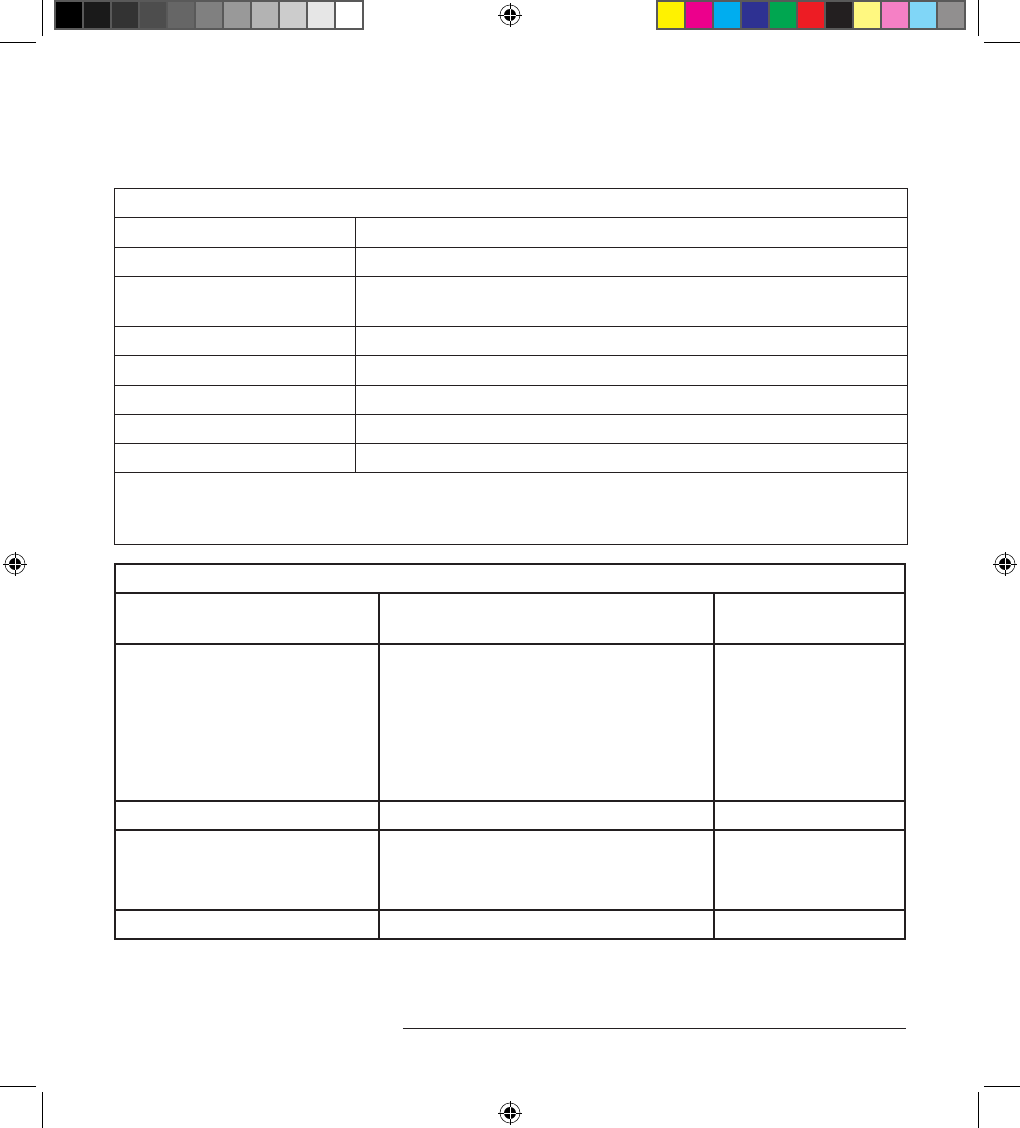
Specications
Table 1. Operating Values for Stimulator Model 2408 and 2412
Programmable parameter Operating range and resolutiona
Number of programs 1 to 10
Number of pulses per sub-
program 1 to 4
Electrode conguration 2 to 24 electrodes and IPG can as anode, cathode, or o
Amplitude 0 to 15 mA per channel (IPG pulse maximum 30 mA) (Max 17 V)
Pulse width 20 to 1500 μs (20 μs resolution)
Frequency 2 to 2000 Hz (64 frequency options)
Ramp on/o O, On: 1, 2, 4, or 8 second duration
a. e Algovita SCS System includes programmable coverage areas with each individual electrode contact
limited to 15 mA. A programming interlock is enforced to limit the coverage area output current to 30
mA or less.
Table 2. Component Materials for Stimulator Model 2408 and 2412
Components Material Material Contacts
Human Tissue
IPG
Case
Header
Titanium
Polysulfone
Polyurethane
Silicone
Silicone rubber
Ye s
Ye s
Ye s
Ye s
Ye s
Setscrews Titanium Ye s
Torque wrench
Handle
Sha
Polyether ether ketone
Stainless steel
Ye s
Ye s
Port plugs Polyurethane Ye s
IPG implant.indb 19 3/3/14 8:46 AM
20 Implant Manual for Stimulator
Specifications
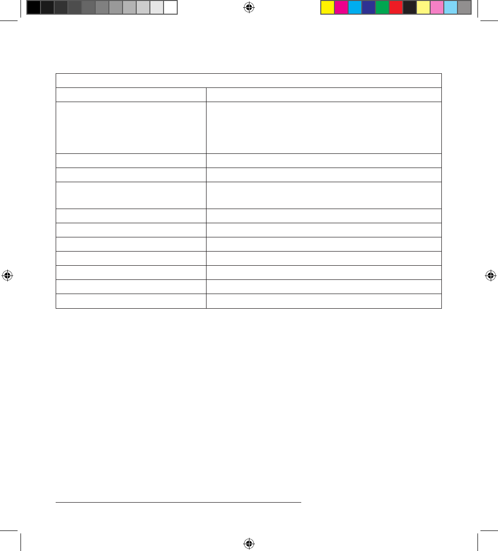
Table 3. Specications for Stimulator Model 2408 and 2412
Description Value
Connector
Type
Diameter
3-Octapolar in-line 2.54 mm (0.100 in) spacing – Model 2408
2-Dodecapolar in-line 2.54 mm (0.100 in) spacing – Model 2412
1.4 mm (0.05 in)
Height 55.0 mm (2.2 in)
Length 58.0 mm (2.3 in)
ickness
Case 9.5 mm (0.4 in)
Weig ht 40.0 g (1.4 oz)
Volume 20.5 cm3 – 2408, 19.5 cm3 – 2412 (1.25 in3 – 2408, 1.19 in3 – 2412)
Battery life 10 years
Power source Lithium ion rechargeable battery – fully recoverable battery
Storage temperature –35° to 55°C (-31° to 131°F)
Radiopaque Identication (ID) code ALG24
Lead retention strength Meets EN45502-1 requirements
Wireless Information
is transmitter is authorized by rule under the Medical Device Radiocommunication Service
(in part 95 of the FCC Rules) and must not cause harmful interference to stations operating in
the 400.150–406.000 MHz band in the Meteorological Aids (ie, transmitters and receivers used
to communicate weather data), the Meteorological Satellite, or the Earth Exploration Satellite
Services and must accept interference that may be caused by such stations, including interference
that may cause undesired operation. is transmitter shall be used only in accordance with the
FCC Rules governing the Medical Device Radiocommunication Service. Analog and digital voice
communications are prohibited. Although this transmitter has been approved by the Federal
Communications Commission, there is no guarantee that it will not receive interference or that any
particular transmission from this transmitter will be free from interference.
IPG implant.indb 20 3/3/14 8:46 AM
Algovita Spinal Cord Stimulation System
Implant Manual for Stimulator 21
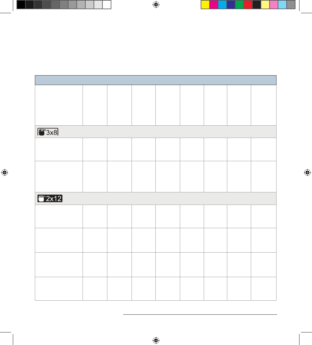
Algovita SCS System Component Compatibility
Only Algovita SCS System components should be used as part of an implanted Algovita SCS
System.
Table 4. Algovita SCS System Component Compatibility
Stimulator
Model 2408
(3x8)
Extension
Model 5208
(1x8)
Stimulator
Model 2412
(2x12)
Extension
Model 5212
(1x12)
Trial
Stimulator
Model 4300
Clinician
Programmer
Model 4500
Programmer
Charger
Model 4200
Pocket
Programmer
Model 4100
For Placing 1–3 8-electrode Leads
Percutaneous Lead
Models 1081-xx1,
1084-xx, 1086-xx
█ █ █ █ █ █
Trial Lead
Models 1081-xxT,
1084-xxT
(Percutaneous)
█ █ █ █ █
For Placing 1–2 12-electrode Leads
Percutaneous Lead
Models 1121-xx,
1124-xx, 1126-xx
█ █ █ █ █ █
Paddle Lead
Model 3000-xx
(3-4-3-2)
█ █ █ █ █ █
Paddle Lead
Model 3101-xx
(2x6)
█ █ █ █ █ █
Trial Lead Models
1121-xxT, 1124-xxT
(Percutaneous)
█ █ █ █ █
1. Denotes length
IPG implant.indb 21 3/3/14 8:46 AM
22 Implant Manual for Stimulator
Algovita SCS System Component Compatibility
IPG implant.indb 22 3/3/14 8:46 AM

IPG implant.indb 23 3/3/14 8:46 AM
©Algostim, LLC 2014
All Rights Reserved
Part Number
1006977
0300-000021-05
Revision 5
March 2014
Algostim, LLC
10675 Naples St. NE
Blaine, MN 55449
763.786.7400
www.algostim.com
Authorized Representative in Europe
Emergo Europe
Molenstraat 15
2513 BH The Hague The Netherlands
(31) (0) 70 345-8570
IPG implant.indb 24 3/3/14 8:46 AM