Nvidia Nforce 650I Users Manual App Note
650I to the manual 026c888d-be1b-4768-a5cb-7cbe930cf1a6
2015-02-02
: Nvidia Nvidia-Nforce-650I-Users-Manual-439726 nvidia-nforce-650i-users-manual-439726 nvidia pdf
Open the PDF directly: View PDF ![]() .
.
Page Count: 135 [warning: Documents this large are best viewed by clicking the View PDF Link!]
- Before You Begin…
- Parts NOT in the Kit
- Intentions of the Kit
- Introduction
- Features
- Ultimate Overclocking
- Guaranteed FSB speeds
- High-speed Memory
- Comprehensive Overclocking Tools
- True x16 PCI Express Support
- DualDDR2 Memory Architecture
- NVIDIA MediaShield™ Storage
- Multiple Disk Setup
- DiskAlert System
- RAID Morphing
- Bootable Multidisk Array
- Networking with NVIDIA nForce
- NVIDIA Native Gigabit Ethernet
- NVIDIA FirstPacket™ Technology
- High Definition Audio (HDA)
- USB 2.0
- Motherboard Specifications
- Features
- Unpacking and Parts Descriptions
- Hardware Installation
- Configuring the BIOS
- Software Installation
- Using the NVIDIA Software
- Index

March 2007
DU-03052-001_v01
User Guide
NVIDIA nForce 650i Ultra
Motherboard for
Intel Processor
Installation and Configuration

Installing and Configuring the NVIDIA nForce 650i Ultra Motherboard
ii

iii
Table of Contents
Before You Begin… ......................................................................................xi
Parts NOT in the Kit........................................................................................xi
Intentions of the Kit.......................................................................................xii
Introduction..................................................................................................1
Features.........................................................................................................1
Ultimate Overclocking ..................................................................................1
Guaranteed FSB speeds................................................................................1
High-speed Memory.....................................................................................1
Comprehensive Overclocking Tools................................................................2
NVIDIA nTune Utility................................................................................2
NV BIOS..................................................................................................2
True x16 PCI Express Support.......................................................................2
DualDDR2 Memory Architecture....................................................................2
NVIDIA MediaShield™ Storage......................................................................2
Multiple Disk Setup......................................................................................3
DiskAlert System..........................................................................................3
RAID Morphing............................................................................................3
Bootable Multidisk Array...............................................................................3
Networking with NVIDIA nForce....................................................................3
NVIDIA Native Gigabit Ethernet.....................................................................4
NVIDIA FirstPacket™ Technology..................................................................4
High Definition Audio (HDA) .........................................................................4

Installing and Configuring the NVIDIA nForce 650i Ultra Motherboard
iv
USB 2.0 ......................................................................................................4
Motherboard Specifications ..............................................................................5
Unpacking and Parts Descriptions ...............................................................8
Unpacking ......................................................................................................8
Equipment......................................................................................................8
NVIDIA nForce 650i Ultra Motherboard .............................................................9
Hardware Installation.................................................................................12
Safety Instructions ........................................................................................12
Preparing the Motherboard.............................................................................13
Installing the CPU......................................................................................13
Installing the CPU Fan................................................................................14
Installing Memory DIMMs...........................................................................14
Installing the Motherboard.............................................................................15
Installing the I/O Shield .............................................................................15
Securing the Motherboard into the Chassis...................................................16
Connecting Cables and Setting Switches..........................................................16
Power Connections ....................................................................................18
24-pin ATX Power (PWR1) ......................................................................18
8-pin ATX 12V Power (PWR2)..................................................................19
Connecting IDE Hard Disk Drives ................................................................19
Connecting Serial ATA Cables .....................................................................20
Connecting Internal Headers.......................................................................21
Front Panel Header ................................................................................21
USB Headers .........................................................................................23
Fan Connections........................................................................................24
COM1.......................................................................................................24
FDD Connector..........................................................................................24
Expansion Slots .........................................................................................25

v
PCI Slots ...............................................................................................25
PCI Express x1 Slot................................................................................26
PCI Express x16 Slots.............................................................................26
Jumper Settings............................................................................................26
Clear CMOS Jumper: CLR_CMOS.................................................................26
Configuring the BIOS ..................................................................................28
Enter BIOS Setup..........................................................................................29
Main Menu....................................................................................................29
Standard CMOS Features Menu ......................................................................32
Date and Time...........................................................................................33
IDE Channel and SATA Channel..................................................................33
Drive A .....................................................................................................36
Halt On.....................................................................................................36
Memory....................................................................................................37
Advanced BIOS Features................................................................................38
Removable Device Priority..........................................................................40
Hard Disk Boot Priority...............................................................................40
Network Boot Priority.................................................................................40
CPU Internal Cache....................................................................................40
Quick Power On Self Test...........................................................................41
First/Second/Third Boot Device...................................................................41
Boot Other Device......................................................................................41
Boot Up NumLock Status............................................................................41
Security Option..........................................................................................42
APIC Mode................................................................................................42
MPS Version Control For OS........................................................................42
Full Screen LOGO Show..............................................................................42

Installing and Configuring the NVIDIA nForce 650i Ultra Motherboard
vi
Advanced Chipset Features ............................................................................43
System Clocks ...........................................................................................44
Frequency Settings.................................................................................45
HT Multiplier..........................................................................................46
Spread Spectrum ...................................................................................46
FSB & Memory Config ................................................................................47
CPU Configuration......................................................................................52
System Voltages........................................................................................53
NVMEM Memory Test.................................................................................55
Load Timing/Voltage Set ............................................................................55
Save Timing/Voltage Set ............................................................................56
System BIOS Cacheable .............................................................................56
HPET Function...........................................................................................56
NVIDIA GPU Ex .........................................................................................56
Integrated Peripherals Menu ..........................................................................57
IDE Function Setup....................................................................................58
RAID Config..............................................................................................59
USB Config................................................................................................59
MAC Config...............................................................................................60
HD Audio ..................................................................................................60
IDE HDD Block Mode .................................................................................60
Onboard FDC Controller .............................................................................60
Onboard Serial Port 1.................................................................................61
Power Management Setup Menu.....................................................................61
ACPI Function............................................................................................62
ACPI Suspend Type ...................................................................................62
Soft-Off by PBNT.......................................................................................62
WOL(PME#) From Soft-Off.........................................................................62

vii
Power On by Alarm....................................................................................62
POWER ON Function..................................................................................63
PnP/PCI Configuration Menu...........................................................................64
Init Display First ........................................................................................65
Reset Configuration Data............................................................................65
Resources Controlled By.............................................................................65
IRQ Resources...........................................................................................66
PCI/VGA Palette Snoop...............................................................................66
Maximum Payload Size...............................................................................66
System Monitor Menu....................................................................................67
Dynamic Fan Control..................................................................................68
Software Installation ..................................................................................69
Windows XP Drivers Install.............................................................................70
Using the NVIDIA Software .......................................................................71
NVIDIA Monitor.............................................................................................72
NVIDIA nTune 5.0.........................................................................................73
Manual Tuning ..........................................................................................74
Adjust Motherboard Settings...................................................................74
System Voltages ....................................................................................76
System Fans..........................................................................................77
Memory Timing......................................................................................78
Adjust GPU Settings ...............................................................................81
Dynamic BIOS Access ................................................................................83
Available BIOS Pages..............................................................................84
General Settings.....................................................................................84
Advanced Settings..................................................................................84
Boot up Setting......................................................................................85

Installing and Configuring the NVIDIA nForce 650i Ultra Motherboard
viii
Automatic Tuning ......................................................................................86
Management.............................................................................................88
View System Information........................................................................88
Adjust Custom Rules ..............................................................................90
System Stability.............................................................................................91
Perform Stability Test.................................................................................91
Storage ........................................................................................................92
Health ......................................................................................................93
View Storage Configuration.....................................................................93
Management.............................................................................................94
Delete Array ..........................................................................................94
Rebuild Array.........................................................................................97
Migrating Array....................................................................................100
Synchronize Array................................................................................102
NVIDIA Networking .....................................................................................104
Performance............................................................................................105
First Packet..........................................................................................105
TCP/IP Acceleration .................................................................................107
System Update............................................................................................110
Motherboard Updates...............................................................................112
Manage Your System BIOS ...................................................................113
BIOS Backup .......................................................................................113
BIOS Flash Options ..............................................................................113
Index.........................................................................................................114
主机板规格简介 ............................................................................................114

ix
List of Figures
Figure 1. NVIDIA nForce 650i Ultra Motherboard Layout ..................................10
Figure 2. Chassis Backpanel Connectors..........................................................11
Figure 3. PWR1 Motherboard Connector .........................................................18
Figure 4. Expansion Slots ..............................................................................25
Figure 5. BIOS CMOS Setup Utility Main Menu.................................................30
Figure 6. Standard CMOS Features Menu........................................................32
Figure 7. Advanced BIOS Features Menu ........................................................38
Figure 8. Advanced Chipset Features..............................................................43
Figure 9. System Clocks Menu........................................................................44
Figure 10. FSB & Memory Config Menu.........................................................47
Figure 11. CPU Configuration Menu..............................................................52
Figure 12. System Voltages Menu.................................................................54
Figure 13. Integrated Peripherals Menu ........................................................57
Figure 14. Power Management Setup Menu...................................................61
Figure 15. PnP/PCI Configuration Menu.........................................................65
Figure 16. System Monitor Menu..................................................................67
Figure 17. NVIDIA Control Panel, Select a Category.......................................72
Figure 18. Performance Control Panel Categories (nTune)..............................73
Figure 19. Adjust Motherboard Settings (nTune)............................................75
Figure 20. Adjust GPU Settings (nTune)........................................................82
Figure 21. Dynamic BIOS Access (nTune) .....................................................83
Figure 22. Tune System Menu (nTune).........................................................87

Installing and Configuring the NVIDIA nForce 650i Ultra Motherboard
x
Figure 23. View System Information (nTune).................................................89
Figure 24. Adjust Custom Rules (nTune).......................................................90
Figure 25. Perform Stability Test ..................................................................92
Figure 26. Storage Control Panel Categories (MediaShield).............................93
Figure 27. View Storage Configuration (MediaShield) .....................................94
Figure 28. Networking Control Panel Categories...........................................105
Figure 29. System Update Application on the NVIDIA Control Panel...............110
Figure 30. Managing Your System Bios Screen.............................................112

xi
Before You Begin…
Parts NOT in the Kit
This kit contains all the hardware necessary to install and connect
your new NVIDIA® nForce® 650i Ultra motherboard. However, it
does not contain the following items that must be purchased
separately to make the motherboard functional.
Intel microprocessor:
Intel Core 2 Extreme, Intel Core 2 Quad, Intel Core 2 Dual,
Pentium
Cooling fan for the microprocessor
System memory support:
Supports dual channel DDR2 533/667/800. Supports up to 8 GBs
DDR2 memory.
Power Supply
To calculate the power you are going to require for your specific
configuration, go to www.slizone.com.
These instructions tell you how to install each of the parts listed so
you can have a functioning motherboard. As you go through the
installation instructions, we are assuming you have purchased the
necessary parts.

Installing and Configuring the NVIDIA nForce 650i Ultra Motherboard
xii
Intentions of the Kit
This kit provides you with the motherboard and all connecting
cables necessary to install the motherboard into a PC cabinet. If you
are building a PC, you will use most of the cables provided in the kit.
If however, you are replacing a motherboard, you will not need many
of the cables.
When replacing a motherboard in a PC cabinet, you will need to
reinstall an operating system even though the current drives have an
operating system.

1
Introduction
Thank you for buying the NVIDIA® nForce® 650i Ultra
Motherboard. This motherboard offers the tools and performance PC
users’ demand.
Features
Ultimate Overclocking
Unleash the underlying hardware. With comprehensive overclocking
tools to push the limits on front side bus (FSB) speed and support
for higher memory speeds, the NVIDIA nForce 650i Ultra MCPs
were designed for overclocking.
Guaranteed FSB speeds
Reach FSB speeds of 1333MHz with a CPU that supports this
specification.
High-speed Memory
This board supports high-speed memory up to DDR2-800 to keep
pace with overclocked system components.

Installing and Configuring the NVIDIA nForce 650i Ultra Motherboard
2
Comprehensive Overclocking Tools
Award-winning NVIDIA overclocking tools provide a complete kit of
tools giving everyone from the most veteran enthusiast to the novice
overclocker the ability to unleash the hardware in their PC.
NVIDIA nTune Utility
NVIDIA nTune™ is a Windows-based utility that has added access to
more settings. Adjust CPU and memory speeds without rebooting.
You can also access most BIOS settings from inside Windows
without having to go into the BIOS. Save and automatically load
profiles for each application you run.
NV BIOS
NV BIOS delivers easy-to-use tuning to let you have full control
over your hardware including processor voltage tables and memory
drive strengths.
True x16 PCI Express Support
One full-bandwidth, 16-lane PCI Express link ensure maximum
graphics performance for next-generation GPUs and games.
DualDDR2 Memory Architecture
A state-of-the-art Dual DDR2 memory controller allows high
bandwidth and low latency data access to the CPU and GPU.
Ensures data and information are relayed through the system as
quickly as possible for incredible performance.
NVIDIA MediaShield™ Storage
NVIDIA MediaShield is a suite of features that safeguards your most
important digital media assets; always reliable, scalable, and accessible.
MediaShield includes RAID and SATA drive support.

Introduction
3
Multiple Disk Setup
Through a simple wizard-based interface, you can effortlessly set up
your drives for better data protection, faster disk access or maximum
storage capacity. MediaShield automatically selects RAID 0, 1, 0+1
or 5 configurations according to your needs. Advanced users can
access RAID options directly.
DiskAlert System
The event of a disk failure, MediaShield users see an image that
highlights which disk has failed to make it easier to identify, replace,
and recover.
RAID Morphing
MediaShield allows users to change their current RAID set-up to
another configuration in a one-step process called morphing. This
eliminates the need to back up data and follow multiple steps in the
process.
Bootable Multidisk Array
MediaShield storage fully supports the use of multi-disk array for
loading the operating system at power-up.
Networking with NVIDIA nForce
NVIDIA networking delivers the highest network throughput at the
lowest CPU utilization. The manageable and stable NVIDIA
networking solution results in better networking management and a
lower total cost of ownership. Only NVIDIA integrates this level of
networking features to allow you to take your online experience to
the next level.

Installing and Configuring the NVIDIA nForce 650i Ultra Motherboard
4
NVIDIA Native Gigabit Ethernet
The industry’s fastest Gigabit Ethernet performance eliminates
network bottlenecks and improves overall system efficiency and
performance.
NVIDIA FirstPacket™ Technology
Be the ‘King of Ping’ with NVIDIA FirstPacket technology. Get
the crystal-clear phone conversations and online gaming performance
you expect. NVIDIA FirstPacket technology assures your game data,
VoIP conversations, and large file transfers are delivered according to
preferences set by you in an intuitive wizard.
High Definition Audio (HDA)
High definition audio brings consumer electronics quality sound to
the PC delivering high quality sound from multiple channels. Using
HDA, systems can deliver 192 kHz/32-bit quality for eight channels,
supporting new audio formats.
USB 2.0
USB 2.0 is standard plug-and-play interface that provides easy-to-use
connectivity for USB devices.

Introduction
5
Motherboard Specifications
Size
ATX form factor of 12 inch x 9.6 inch
Microprocessor support
Intel Core 2 Extreme, Intel Core 2 Quad, Intel Core 2 Dual,
Pentium
Operating systems:
Supports Windows XP 32bit/64bit and Windows Vista 32bit/64bit
Contains NVIDIA nForce 650i Ultra MCP and SPP
System Memory support
Supports dual channel JEDEC DDR2-800. Supports up to 8 GBs
DDR2 memories.
USB 2.0 Ports
¾ Supports hot plug
¾ Eight USB 2.0 ports (four rear panel ports, four onboard USB
headers)
¾ Supports wake-up from S1 and S3 mode
¾ Supports USB 2.0 protocol up to 480 Mbps transmission rate
¾ 300MBps data transfer rate
¾ Four Serial ATA II connectors
¾ NVIDIA MediaShield RAID with support for RAID 0, RAID
1, RAID 0+1, RAID 5, and JBOD
¾ Supports hot plug and NCQ (Native Command Queuing )
Onboard LAN
¾ Single LAN interface built-in onboard
¾ Supports 10/100/1000 Mbit/sec Ethernet
Audio
¾ Azalia High-Definition audio
¾ Supports 8-channel audio
¾ Supports S/PDIF output

Installing and Configuring the NVIDIA nForce 650i Ultra Motherboard
6
¾ Supports Jack-Sensing function

Introduction
7
PCI Express x16 Support
¾ Supports 4 GB/sec (8 GB/sec concurrent) bandwidth
¾ Low power consumption and power management features
Green Function
¾ Supports ACPI (Advanced Configuration and Power Interface)
¾ Supports S0 (normal), S1 (power on suspend), S3 (suspend to
RAM), S4 (Suspend to disk - depends on OS), and S5 (soft -
off)
Expansion Slots
¾ Three PCI slots
¾ Two PCI Express x1 slot
¾ One PCI Express x16 Graphics slot
8
Unpacking and
Parts Descriptions
Unpacking
The NVIDIA nForce 650i Ultra motherboard comes with all the
necessary cables for adding a motherboard to a new chassis. If you
are replacing a motherboard, you may not need many of these cables.
Be sure to inspect each piece of equipment shipped in the packing
box. If anything is missing or damaged, contact your reseller.
All parts shipped in this kit are RoHS-compliant (lead-free) parts.
Equipment
The following equipment is included in the NVIDIA nForce 650i
Ultra motherboard box.
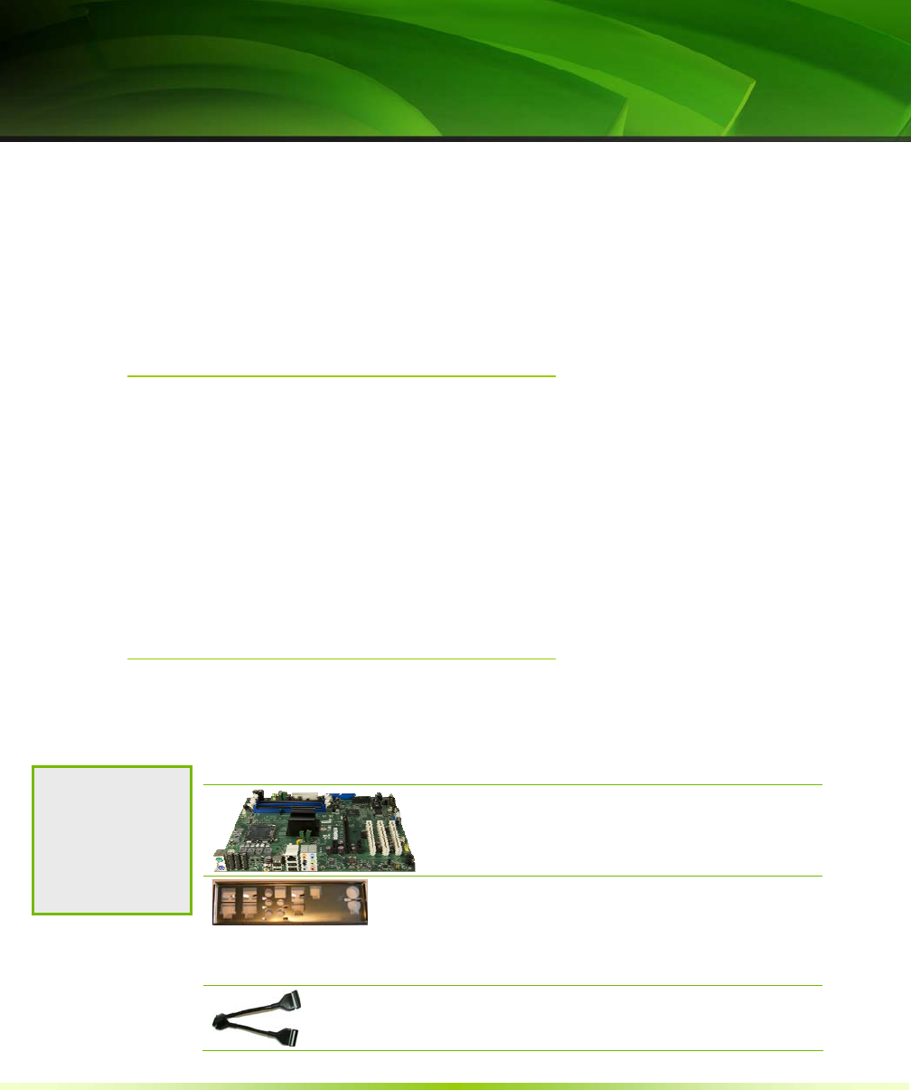
NVIDIA nForce 650i Ultra Motherboard
This PCI Express motherboard contains the NVIDIA
nForce 650i Ultra SPP and MCP.
I/O Shield
Installs in the chassis to block radio frequency
transmissions, protect internet components from
dust and foreign objects and aids in proper airflow
within the chassis.
Floppy Cable
Used to attach a floppy drive to the motherboard.
Note to Partners:
Revise this list with
the equipment you
are shipping in the
kit.

Unpacking and Parts Description
9
2-Port SATA Power Cable (Qty Two)
USB 2.0 4-Port Cable
Provides four additional USB ports to either the
front or back panels of the chassis.
SATA Signal Cable (Qty Four)
Used to support the Serial ATA protocol and each
one connects a single drive to the motherboard
Comm2 Bracket Cable
IDE-ATA 133 HDD Cable
NVIDIA nForce 650i Ultra
Motherboard
The NVIDIA nForce 650i Ultra motherboard with the NVIDIA
nForce 650i Ultra SPP and MCP processors is a PCI Express
motherboard. Figure 1 shows the motherboard and Figures 2 shows
the back panel connectors.
Installing and Configuring the NVIDIA nForce 650i Ultra Motherboard
10
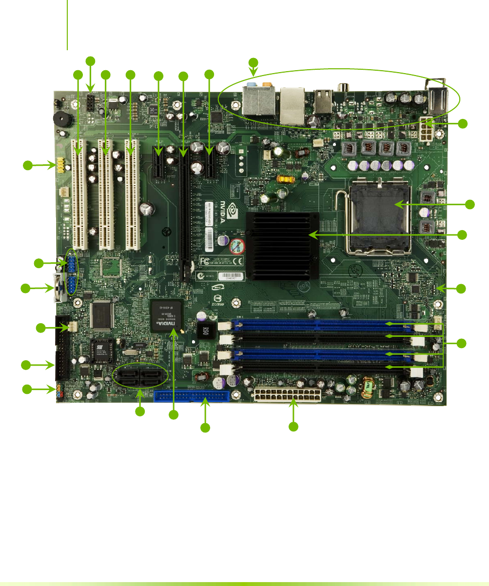
1. CPU Socket 8. Serial-ATA connectors 15. PCI slots
2. NVIDIA SPP 9. Front panel connector 16. Front Panel Audio connector
3. CPU fan connector 10. Floppy drive connector 17. PCI Express x1 slot
4. DDR DIMM slots 0 - 3 12. System fan connector 18. PCI Express x16 slot
5. 24-pin ATX power connector 12. Motherboard battery 19. Backpanel connectors (Figure 2)
6. IDE connector 13. USB headers 20. 8-pin ATX_12V power connector
7. NVIDIA MCP 14. Serial connector
Figure 1. NVIDIA nForce 650i Ultra Motherboard Layout
2
1
4
3
5
7
9
6
10
15 15 15 18 17 19
20
8
12
17
13
11
16
14
Unpacking and Parts Description
11
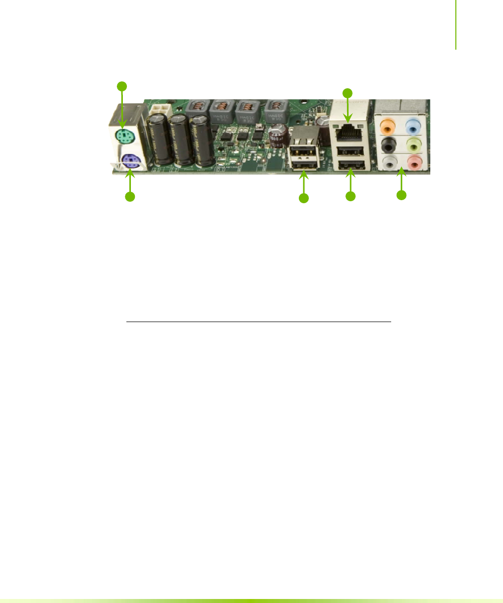
1. PS/2 Mouse Port
2. PS/2 Keyboard Port
3. USB 2.0 ports (two)
4. Lan Port with LEDs to indicate status.
• Yellow/Light Up/Blink = 10 Mbps/Link/Activity
• Yellow and Green/Light Up/Blink = 100 Mbps/link/Activity
• Green/Light Up/Blink = 1000 Mbps/Link/Activity
5. USB 2.0 Ports (two)
6. Port 2-Channel 4-Channel 6-Channel/8-Channel
Blue Line-In Line-In Line-In
Green Line-Out Front Speaker Out Front Speaker Out
Pink Mic In Mic In Mic In
Orange Center/Subwoofer
Black Rear Speaker Out Rear Speaker Out
Grey
Figure 2. Chassis Backpanel Connectors
1
23
4
56

12
Hardware Installation
This section will guide you through the installation of the
motherboard. The topics covered in this section are:
Preparing the motherboard
¾ Installing the CPU
¾ Installing the CPU fan
¾ Installing the memory
Installing the motherboard
Connecting cables and setting switches
Safety Instructions
To reduce the risk of fire, electric shock, and injury, always follow basic
safety precautions.
Remember to remove power from your computer by disconnecting the
AC main source before removing or installing any equipment from/to the
computer chassis.
Hardware Installation
13
Preparing the Motherboard
The motherboard shipped in the box does
not
contain a CPU or
memory. You need to purchase a CPU, a CPU fan assembly, and
memory to complete this installation.
Installing the CPU
Be very careful when handling the CPU. Make sure not to bend or
break any pins on the back. Hold the processor only by the edges
and do not touch the bottom of the processor.
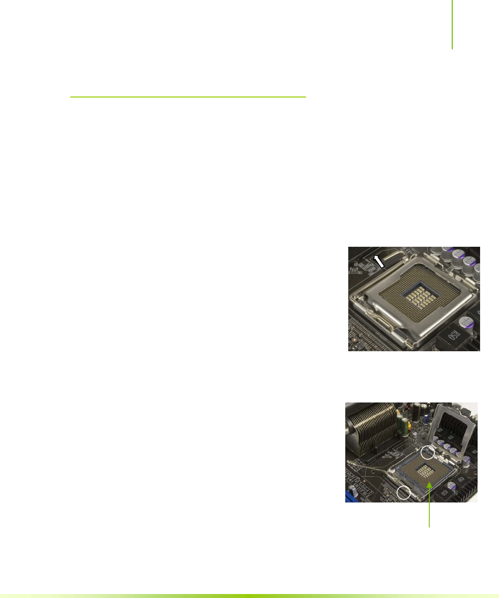
Use the following procedure to install the
CPU onto the motherboard.
1. Unhook the socket lever by pushing down
and away from the socket.
2. Lift the load plate. There is a protective
socket cover on the load plate to protect
the socket when there is no CPU installed.
3. Remove the protective socket cover from the load plate.
4. Remove the processor from its protective
cover, making sure you hold it only by the
edges.
It is a good idea to save the cover so that
whenever you remove the CPU, you have
a safe place to store it.
5. Align the notches in the processor with
the notches on the socket.
6. Lower the processor straight down into the socket with out
tilting or sliding it into the socket Align notches with
notches on the CPU
Installing and Configuring the NVIDIA nForce 650i Ultra Motherboard
14
Note: Make sure the CPU is fully seated and level in the
socket.
7. Close the load plate over the CPU and press
down while you close and engage the socket
lever.
Installing the CPU Fan
There are many different fan types that can be used with this
motherboard. Follow the instruction that came with you fan
assembly. Be sure that the fan orientation is correct for your chassis
type and your fan assembly.
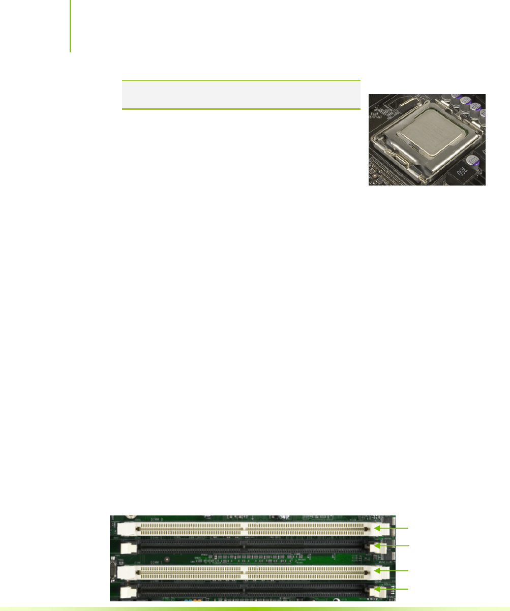
Installing Memory DIMMs
Your new motherboard has four 1.8V 240-pin slots for DDR2
memory. These slots support 256 Mb, 512 Mb and 1 Gb DDR2
technologies for x8 and x16 devices. They also support dual channel
DDR2 memory technology up to 10.7GB/s. There must be at least
one memory bank populated to ensure normal operation. Use the
following the recommendations for installing memory. (See Figure 1
on page 10 for the location of the memory slots on the card)
One DIMM: Install into slot 0. You can install the DIMM into
any slot, however, slot 0 is preferred.
Two DIMMs: Install into either slots 0 and 1 or 2 and 3. The
idea is to not have the DIMMs in adjacent slots.
Four DIMMS: Install into slots 0, 1, 2, and 3.
DIMM Slot 0
DIMM Slot 2
DIMM Slot 1
DIMM Slot 3
CPU side
Card-edge side

Hardware Installation
15
Use the following procedure to install memory DIMMs into the slots
on the motherboard. Note that there is only one gap near the center
of the DIMM slot. This slot matches the slot on the memory
DIMM to ensure the component is installed properly.
1. Unlock a DIMM slot by pressing the module clips outward.
2. Align the memory module to the DIMM slot, and insert the
module vertically into the DIMM slot. The plastic clips at both
sides of the DIMM slot automatically lock the DIMM into the
connector.
Installing the Motherboard
The sequence of installing the motherboard into the chassis depends
on the chassis you are using and if you are replacing an existing
motherboard or working with an empty chassis. Determine if it
would be easier to make all the connections prior to this step or to
secure the motherboard and then make all the connections. Use the
following procedure to install the I/O shield and secure the
motherboard into the chassis.
Note: Be sure that the CPU fan assembly has enough clearance for the chassis
covers to lock into place and for the expansion cards. Also make sure the
CPU Fan assembly is aligned with the vents on the covers.
Installing the I/O Shield
The motherboard kit comes with an I/O shield that is used to block
radio frequency transmissions, protects internal components from dust
and foreign objects, and promotes correct airflow within the chassis.
Before installing the motherboard, install the I/O shield from the
inside of the chassis. Press the I/O shield into place and make sure it

Installing and Configuring the NVIDIA nForce 650i Ultra Motherboard
16
fits securely. If the I/O shield does not fit into the chassis, you
would need to obtain the proper size from the chassis supplier.
Securing the Motherboard into the Chassis
Most computer chassis have a base with mounting studs or spacers to
allow the mother board to be secured to the chassis and help to
prevent short circuits. If there are studs that do not align with a
mounting hole on the motherboard, it is recommended that you
remove that stud to prevent the possibility of a short circuit.
1. Carefully place the motherboard onto the studs/spacers located
inside the chassis.
2. Align the mounting holes with the studs/spacers.
3. Align the connectors to the I/O shield.
4. Ensure that the fan assembly is aligned with the chassis vents
according to the fan assembly instruction.
5. Secure the motherboard with a minimum of eight-to-ten screws.
Connecting Cables and
Setting Switches
This section takes you through all the connections and switch
settings necessary on the motherboard. This will include:
Power Connections
¾ 24-pin ATX power (PWR1)
¾ 8-pin ATX 12V power (PWR2)
Internal Headers
¾ Front panel
¾ USB Headers
¾ Audio
¾ COM

Installing and Configuring the NVIDIA nForce 650i Ultra Motherboard
18
Power Connections
This motherboard requires an ATX power supply. Make sure you
have enough power to cover all the expansion cards you will be
installing. To determine what you power requirements are for your
specific configuration, refer to www.slizone.com.
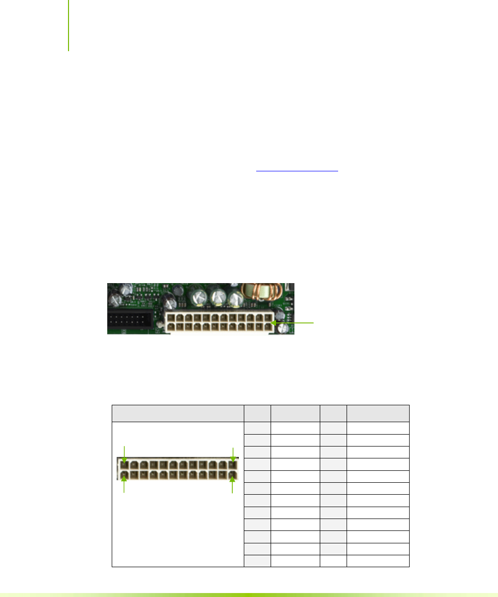
24-pin ATX Power (PWR1)
PWR1 is the main power supply connector located along the edge of
the board next to the DIMM slots. Make sure that the power supply
cable and pins are properly aligned with the connector on the
motherboard. Firmly plug the power supply cable into the connector
and make sure it is secure.
Figure 3. PWR1 Motherboard Connector
Table 1. PWR1 Pin Assignments
Connector Pin Signal Pin Signal
1 +3.3V 13 +3.3V
2 +3.3V 14 -12V
3 GND 15 GND
4 +5V 16 PS_ON
5 GND 17 GND
6 +5V 18 GND
7 GND 19 GND
8 PWROK 20 RSVD
9 +5V_AUX 21 +5V
10 +12V 22 +5V
11 +12V 23 +5V
24 13
12 1
12 +3.3V 24 GND
PWR1 connector
Plug power cable from system
power supply to PWR1
Card edge
Hardware Installation
19
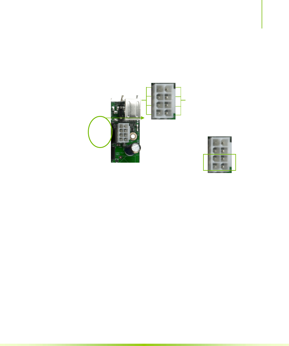
8-pin ATX 12V Power (PWR2)
PWR2, the 8-pin ATX 12V power connection, is used to provide
power to the CPU. Align the pins to the connector and press firmly
until seated.
It is strongly recommended that you use an 8-pin ATX 12V power
supply; however, if you have a four-pin power supply, plug the
connector to pins 3, 4, 7, and 8 as shown.
Connecting IDE Hard Disk Drives
The IDE connector supports Ultra ATA 133/100/66 IDE hard disk
drives.
1. Connect the blue connector (the cable end with a single connector)
to the motherboard.
2. Connect the black connector (the cable with the two closely
spaced black and gray connectors) to the Ultra ATA master device.
3. Connect the gray connector to a slave device.
If you install two hard disk drives, you must configure the second
drive as a slave device by setting its jumper accordingly. Refer to the
hard disk documentation for the jumper settings.
Connect a four-pin
power plug to pins
3, 4, 7, and 8.
GND
12V
1
8
4
5
1 5
Backpanel connector edge.
Installing and Configuring the NVIDIA nForce 650i Ultra Motherboard
20
Note: If an ATA-66/100 disk drive and a disk drive using any other IDE transfer
protocol are attached to the same cable, the maximum transfer rate between
the drives may be reduced to that of the slowest drive.
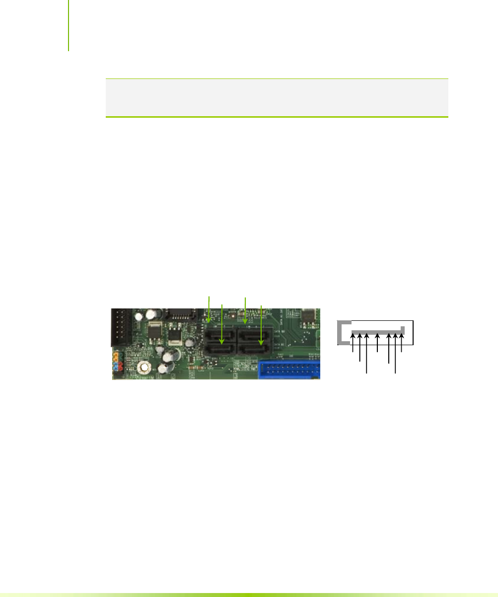
Connecting Serial ATA Cables
The Serial ATA II connector is used to connect the Serial ATA II
device to the motherboard. These connectors support the thin Serial
ATA II cables for primary storage devices. The current Serial ATA
II interface allows up to 300MB/s data transfer rate.
There are four serial ATA connectors on the motherboard that
support RAID 0, RAID 1, RAID 5, RAID 0+1 and JBOD
configurations.
1. Connect the locking cable end to the
motherboard connector.
2. Connect the end without the lock to the drive.
SATA 4 SATA 3
SATA 2 SATA 1
GND GND GND
TX+ RX+
TX- TX-
Hardware Installation
21
Connecting Internal Headers
Front Panel Header
The front panel header on this motherboard is one
connector used to connect the following four cables:
PWRLED
Attach the front panel power LED cable to
these two pins of the connector.
The Power LED indicates the system’s
status. When the system is in S0 status,
the LED is
on. When the system is in S1, S3, S4, S5
status, the LED is off.
Note: The power LED cable in some chassis is a three pin connector with
the pins installed in positions 1 and 3. If your chassis has a three
pin connector, you will need to remove pin 3 and put it into
position 2 or you can use a pair of scissors to cut out position 2.
Most chassis come with a two pin connector.
PWRSW
Attach the power button cable from the case to these two pins.
Pressing the power button on the front panel turns the system on
off rather than using the power supply button.
HD_LED
Attach the hard disk drive indicator LED cable to these two pins.
The HDD indicator LED indicates the activity status of the hard
disks.
RESET
Attach the Reset switch cable from the front panel of the case to
these two pins. The system restarts when the RESET switch is
pressed.
PWRSW - +
PWRLED
1
2
1
9
10
HD_LED
RESET - +
No
Connect
Blan
k
Installing and Configuring the NVIDIA nForce 650i Ultra Motherboard
22
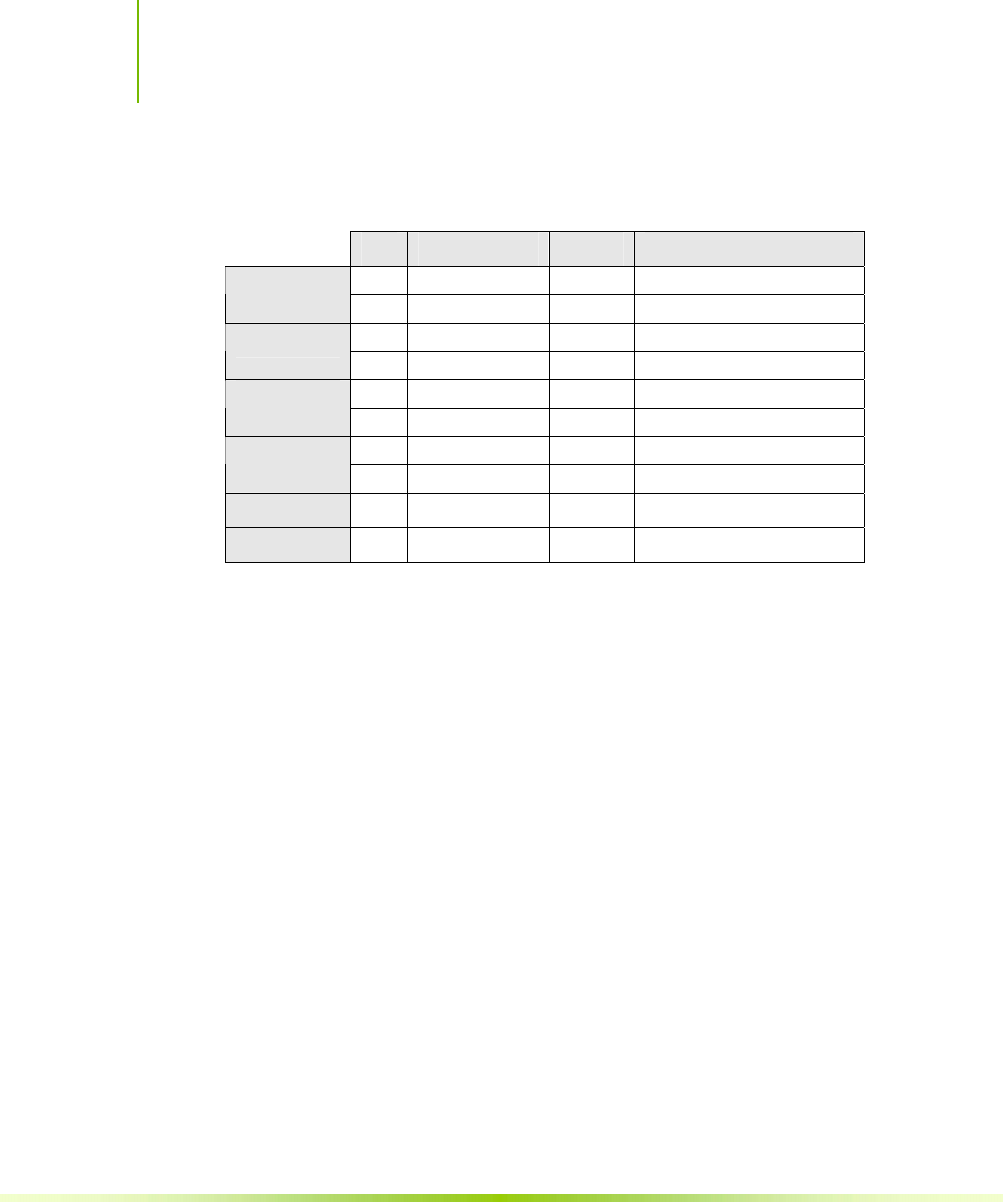
Table 2. Front Panel Header Pins
Pin Signal In/Out Description
1 HD_PWR Out Hard disk LED pull-up to +5V
HD_LED 3 HDA# Out Hard disk active LED
2 HDR_BLNK_GRN Out Front panel green light
PWRLED 4 HDR_BLNK_YEL Out Front panel yellow light
5 GND Ground
RESET 7 FP_RESET# In Reset switch
6 SWITCH_ON# In Power switch
PWRSW 8 GND Ground
No Connect 9 No Connect
Empty 10 Empty
Hardware Installation
23
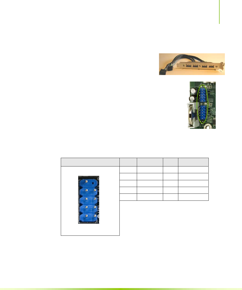
USB Headers
This motherboard contains four (4) USB
2.0 ports that are exposed on the rear
panel of the chassis. The motherboard also
contains two
10-pin internal header connectors onboard that can be
used to connect an optional external bracket containing
four (4) more USB 2.0 ports.
1. Secure the bracket to either the front or rear
panel of your chassis (not all chassis are equipped
with the front panel option).
2. Connect the two ends of the cables to the USB
2.0 headers on the motherboard.
Table 3. USB 2.0 Header Pins
Connector Pin Signal Pin Signal
1 5V_DUAL 2 5V_DUAL
3 D- 4 D-
5 D+ 6 D+
7 GND 8 GND
9 Empty 10 No Connect
USB 2.0 Header Connector
9
7
5
3
1
10
8
6
4
2
Installing and Configuring the NVIDIA nForce 650i Ultra Motherboard
24
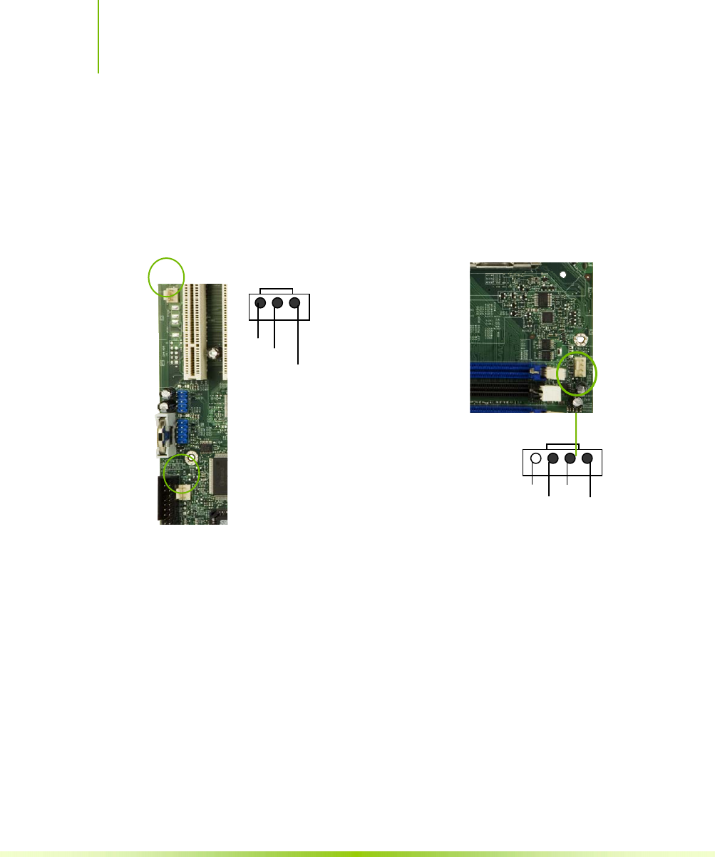
Fan Connections
There are two fan connections, the system fan and the CPU fan.
The fan speed can be detected and viewed in the System Monitor
section of the CMOS Setup. Both fans are automatically turned off
after the system enters S3, S4 and S5 mode.
COM1
The motherboard kit provides an additional serial COM header for
your machine. Connect one side of a switching cable to the header
and then attach the serial COM device to the other side of the cable.
FDD Connector
The motherboard supports a standard 360K, 720K, 1.2M, 1.44m, and
a 2.88M floppy disk drive (FDD).
Note that the CPU fan cable can be
either a 3-pin or a 4-pin connector.
Connect a 3-pin connector to pins 1, 2,
and 3 on the motherboard connector.
CPU Fan Connector
4 3 2 1
GND SENSE
PWR CONTRO
L
Fan Connector
3 2 1
GND
+12
V
SENSE
System fan connector CPU fan connector
Hardware Installation
25
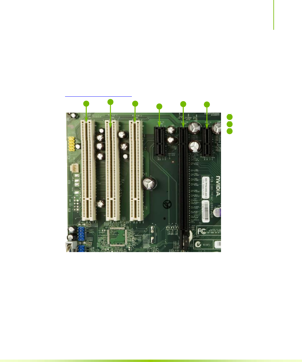
Expansion Slots
The NVIDIA nForce 650i Ultra motherboard contains six expansion
slots, one PCI Express slot and three PCI slots. For a full list of
PCI Express x16 graphics card supported by this motherboard, go to
www.nvidia.com/estore.
Figure 4. Expansion Slots
PCI Slots
The three PCI slots support many expansion cards such as a LAN
card, USB card, SCSI card and other cards that comply with PCI
specifications. When installing a card into the PCI slot, be sure that
it is fully seated. Secure the card’s metal bracket to the chassis back
panel with the screw used to hold the blank cover.
1
2
1 – PCI slots
2 – x1 PCIe slots
4 – Primary PCIe x16
slot (GPU1)
1
1
2
3

Installing and Configuring the NVIDIA nForce 650i Ultra Motherboard
26
PCI Express x1 Slot
There are two PCI Express x1 slots that are designed to
accommodate less bandwidth-intensive cards, such as a modem or
LAN card. The x1 slot provides 250 MB/sec bandwidth.
PCI Express x16 Slots
There is one PCI Express x16 slot that is reserved for a graphics or
video card. The bandwidth of the x16 slot is up to 4GB/sec
(8GB/sec concurrent).
When installing a PCI Express x16 card, be sure the retention clip
snaps and locks the card into place. If the card is not seated
properly, it could cause a short across the pins. Secure the card’s
metal bracket to the chassis back panel with the screw used to hold
the blank cover.
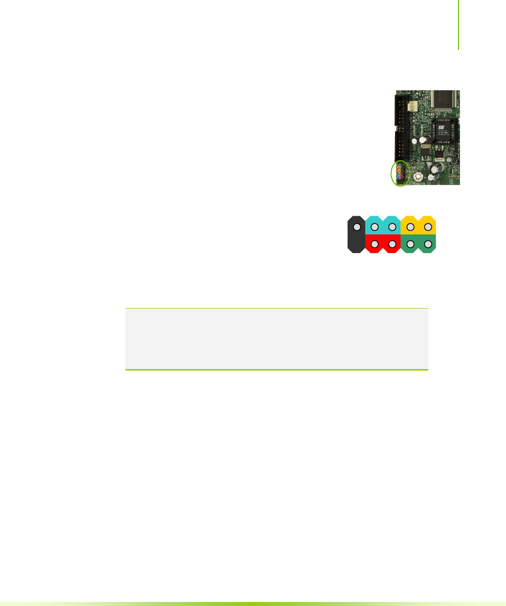
Jumper Settings
The motherboard contains a 3-pin BIOS configuration jumper that
enables all board configurations to be done in the BIOS Setup
program.
The silk screen on the motherboard shows a ∆ next to pin 1.
Clear CMOS Jumper: CLR_CMOS
The motherboard uses the CMOS RAM to store all the set
parameters. The CMOS can be cleared by removing the CMOS
jumper.
Use the following procedure to clear CMOS:
1. Turn off the AC power supply and connect pins 1 and 2
together using the jumper cap.

Hardware Installation
27
2. Return the jumper setting to normal (pins 2 and
3. Together with the jumper cap).
4. Turn the AC power supply back on.

28
Configuring the BIOS
This section discusses how to change the system settings through the
BIOS Setup menus. Detailed descriptions of the BIOS parameters are
also provided.
This section includes the following information:
Enter BIOS Setup
Main Menu
Standard CMOS Features
Advanced BIOS Features
Advanced Chipset Features
Integrated Peripherals
Power Management Setup
PnP/PCI Configurations
System Monitor
Configuring the BIOS
29
Enter BIOS Setup
The BIOS is the communication bridge between hardware and
software. Correctly setting the BIOS parameters is critical to maintain
optimal system performance.
Use the following procedure to verify/change BIOS settings.
1. Power on the computer,
2. Press the Del key when the following message briefly displays at
the bottom of the screen during the Power On Self Test (POST).
Press F1 to continue, DEL to enter Setup.
Pressing Del takes you to the Phoenix-Award BIOS CMOS Setup
Utility.
Note: It is strongly recommended that you do not change the default BIOS
settings. Changing some settings could damage your computer.
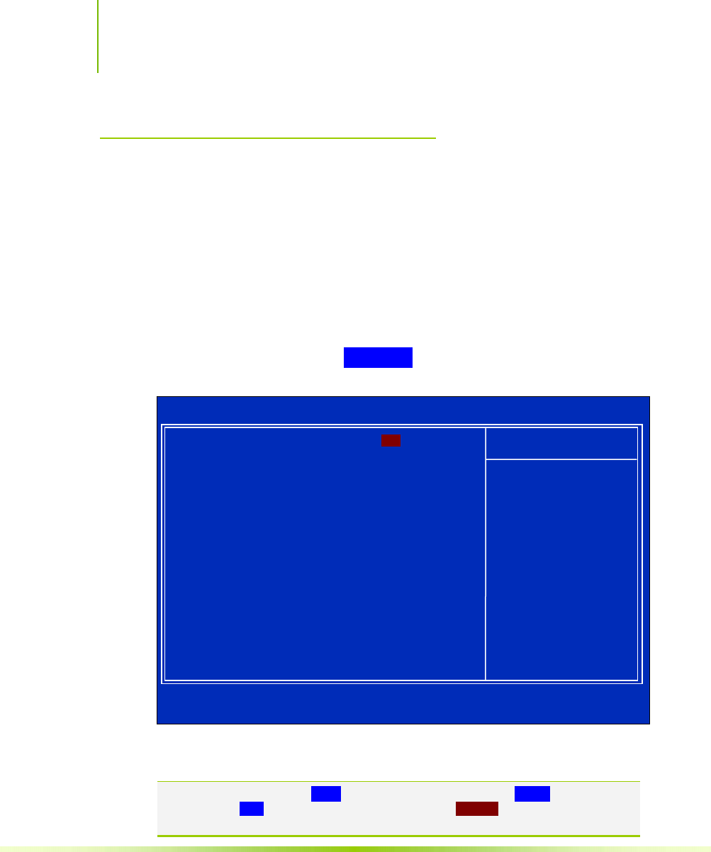
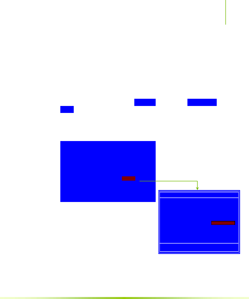
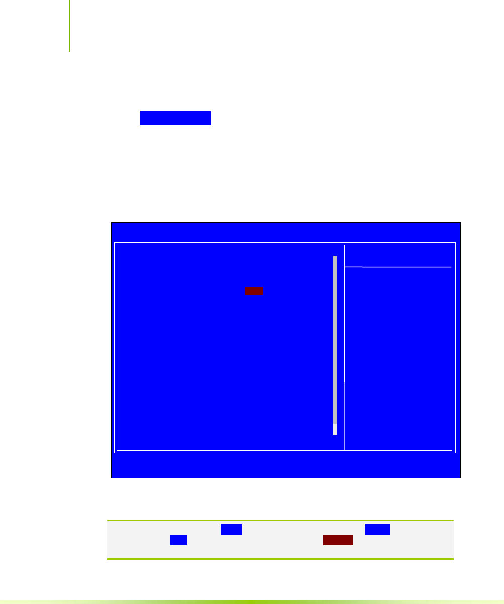
Main Menu
The main menu allows you to select from the list of setup functions
and two exit choices. Use the Page Up and Page Down keys to scroll
through the options or press Enter to display the associated submenu.
Use the arrow keys to position the selector in the option you
choose. To go back to the previous menu, press Esc.
Note: Note that on the BIOS screens all data in white is for information only, data in
yellow is changeable, data in blue is non-changeable, and data in a
red box is highlighted for selection.

Installing and Configuring the NVIDIA nForce 650i Ultra Motherboard
30
Figure 5. BIOS CMOS Setup Utility Main Menu
Standard CMOS Features
Use this menu to set up the basic system configuration.
Advanced BIOS Features
Use this menu to set up the advanced system features and boot
sequence.
Advanced Chipset Features
Use this menu to optimize system performance and configure
clocks, voltages, memory timings, and more.
Integrated Peripherals
Use this menu to set up onboard peripherals such as IDE, RAID,
USB, LAN, and MAC control.
Power Management Setup
Use this menu to configure power management, power on, and
sleep features.
Phoenix – AwardBIOS CMOS Setup Utility
` System Monitor
Load Defaults
Set Password
Save & Exit Setup
Exit Without Saving
Esc : Quit
F10 : Save & Exit Setup
: Select Item
Time, Date, Hard Disk Type..,
` Standard CMOS Features
` Advanced BIOS Features
` Advanced Chipset Features
` Integrated Peripherals
` Power Management Setup
` PnP/PCI Configurations

Configuring the BIOS
31
PnP/PCI Configurations
Use this menu to modify the system’s Plug-and-Play and PCI
configurations.
System Monitor
Use this menu to monitor the real-time system status of your PC,
including temperature, voltages, and fan speed.
The following items on the CMOS Setup Utility main menu are
commands rather than submenus:
Load Defaults
Load default system settings.
Set Password
Use this command to set, change, and disable the password used to
access the BIOS menu.
Save & Exit Setup
Use this command to save settings to CMOS and exit setup.
Exit Without Saving
Use this command to abandon all setting changes and exit setup.
The following two items on the CMOS Setup Utility main menu are
status indicators:
Installing and Configuring the NVIDIA nForce 650i Ultra Motherboard
32
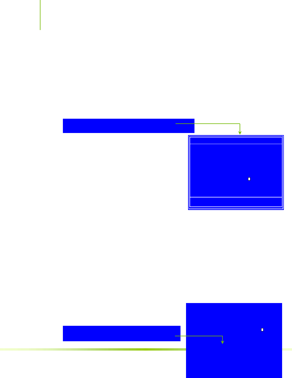
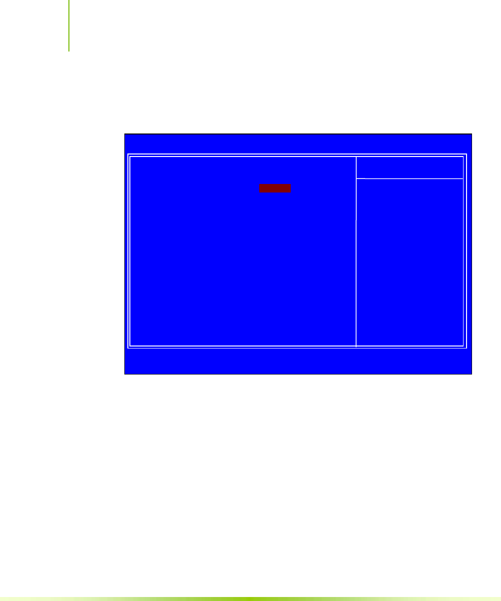
Standard CMOS Features
Menu
The Standard CMOS Features menu is used to configure the standard
CMOS information, such as the date, time, HDD model, and so on.
Use the Page Up and Page Down keys to scroll through the options
or press Enter to display the sub-menu. Use the arrow keys to
position the selector in the option you choose. To go back to the
previous menu, press Esc.
The information shown in Item Help corresponds to the option
highlighted.
Figure 6. Standard CMOS Features Menu
Note: Note that all data in white is for information only, data in yellow is changeable,
data in blue is non-changeable, and data in a red box is highlighted for
selection.
:Move Enter:Select +/-/PU/PD:Value F10:Save ESC:Exit F1:General Help
F
5: Previous V
a
lues F7:Defaults
` IDE Channel (.) Master [None]
` IDE Channel (.) Slave [None]
` SATA Channel 1 Master [None]
` SATA Channel 2 Master [None]
` SATA Channel 3 Master [None]
` SATA Channel 4 Master [None]
Drive A [1.44, 3.5 in.]
Halt On [All , But Keyboard]
Base Memory 640K
Extended Memory 1047552K
Total Memory 1048576K
Date (mm:dd:yy) Sat, Jul 01 2006
Time (hh:mm:ss) 12 : 48: 23 Item Help
Main Level `
Change the day, month,
year and century
Phoenix – AwardBIOS CMOS Setup Utility
Standard CMOS Features
Configuring the BIOS
33
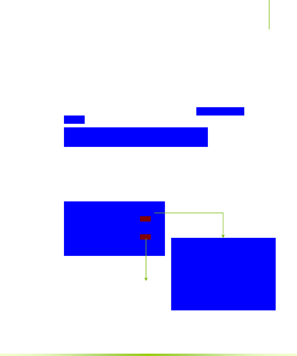
Date and Time
Using the arrow keys, position the cursor over the month, day, and
year. Use the Page Up and Page Down keys to scroll through dates
and times. Note that the weekday (Sun through Sat) cannot be
changed. This field changes to correspond to the date you enter.
Note that the hour value is shown in a
24-hour clock format. Time is represented as hour : minute :
second.
IDE Channel and SATA Channel
Use these functions to detect and configure the individual IDE and
SATA channels. Select a channel and press Enter to display the
IDE/SATA sub-menu.
` IDE Channel (.) Master [None]
` IDE Channel (.) Slave [None]
` SATA Channel 1 Master [None]
` SATA Channel 2 Master [None]
` SATA Channel 3 Master [None]
` SATA Channel 4 Master [None]
Date (mm:dd:yy) Sat, Jul 01 2006
Time (hh:mm:ss) 14 : 48: 43
Press ENTER to display
IDE Channel sub-menu
IDE HDD Auto-Detect [Press Enter]
IDE Channel 0 Slave [Manual}
Access Mode [CHS]
Capacity 0 MB
Cylinder [ 0]
Head [ 0]
Precomp [ 0]
Landing Zone [ 0]
Sector [ 0]
Press ENTER to display
SATA Channel sub-menu

Installing and Configuring the NVIDIA nForce 650i Ultra Motherboard
34
IDE Auto-Detect [Press Enter]
Extended IDE Drive [None}
Access Mode Auto
Capacity 0 MB
Cylinder 0
Head 0
Precomp 0
Landing Zone 0
Sector 0
Configuring the BIOS
35
Press Enter to auto-detect IDE and SATA channels in the system.
Once the channel is detected, the values for Capacity, Cylinder,
Heads, Precomp, Landing Zone, and Sector are automatically filled in.
None
There is no HDD installed or set.
Auto
The system can auto-detect the hard disk when booting up.
Manual
When you set the channel to [Manual] and change Access Mode to
[CHS], you can then enter the number of cylinders, heads,
Precomp, landing zone, and sector. You can manually enter the
values or you can press Enter to display a window that tells you
the min and max values.
The BIOS supports the following HDD
Access Modes:
¾ CHS
For HDD less than 528 MB.
¾ LBA
For HDD greater than 528 MB and
supporting LBA (Logical Block
Addressing).
¾ Large
For HDD greater than 528 MB but not supporting LBA.
IDE HDD Auto-Detect [Press Enter]
IDE Channel 0 Slave [Manual}
Access Mode [CHS]
Capacity 0 MB
Cylinder .....0
Head [ 0]
Precomp [ 0]
Landing Zone [ 0]
Sector [ 0] Cylinder
Min= 0
Max=65535
Key in a DEC number :
:Move ENTER:Accept ESC:Abort
Press ENTER to display sub-menu
or enter number manually
Installing and Configuring the NVIDIA nForce 650i Ultra Motherboard
36
Drive A
None ..... [ ]
360K, 5.25 in. ..... [ ]
1.2M, 5.25 in. ..... [ ]
720K, 3.5 in. ..... [ ]
1.44M, 3.5 in. ..... [ ]
2.88M, 3.5 in. ..... [ ]
:Move ENTER:Accept ESC:Abort
Halt On
All Errors ..... [ ]
No Errors ..... [ ]
All , But Keyboard ..... [ ]
All , But Diskette ..... [ ]
All , But Disk/Key ..... [ ]
:Move ENTER:Accept ESC:Abort
¾ Auto
Recommended mode.
Drive A
The Drive A option allows you to select the kind of FDD to install.
Options are:
None
360K, 5.25 in.
1.2M, 5.25 in.
720K, 3.5 in.
1.44M, 3.5 in.
2.88M, 3.5 in.
Use the Page Up and Page Down keys to
scroll through the options or press Enter
to display the sub-menu. Use the arrow keys to position the
selector in the option you choose. Press Enter to accept the changes
and return to the Standard CMOS Features menu.
Halt On
Halt On determines whether or not the computer stops if an error is
detected during power on. Use the Page Up and Page Down keys to
scroll through the options or press Enter to display the Halt On sub-
menu. Use the arrow keys to position the selector in the option
you choose. Press Enter to accept the
changes and return to the Standard
CMOS Features menu.
Drive A [1.44, 3.5 in.]
Halt On [All , But Keyboard]
Drive A [1.44, 3.5 in.]
Halt On
[
All
,
But Ke
y
board
]
Press ENTER to dis
p
la
y
sub-menu
Press ENTER to dis
p
la
y
sub-menu

Configuring the BIOS
37
Base Memory 640K
Extended Memory 1047552K
Total Memory
1048576K
All Errors
Whenever the BIOS detects a nonfatal error, the system stops and
prompts you.
No Errors
System boot does not stop for any detected errors.
All, But Keyboard
System boot does not stop for keyboard errors, but does stop for
all other errors.
All, But Diskette
The system boot does not stop for a diskette error but will stop
for all other errors.
All, But Disk/Key
The system boot does not stop for a keyboard or disk error, but
will stop for all other errors.
Memory
These settings are display-only values that are determined by the BIOS
POST (Power-On Self Test).
Base Memory
BIOS POST determines the
amount of base (or conventional) memory installed in the system.
Extended Memory
BIOS determines how much extended memory is present during
the POST.
Total Memory
This value represents the total memory of the system.
Installing and Configuring the NVIDIA nForce 650i Ultra Motherboard
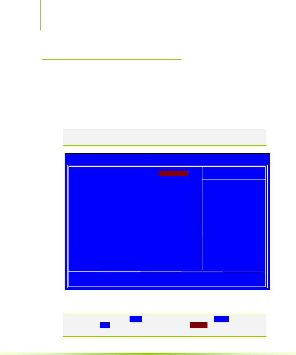
38
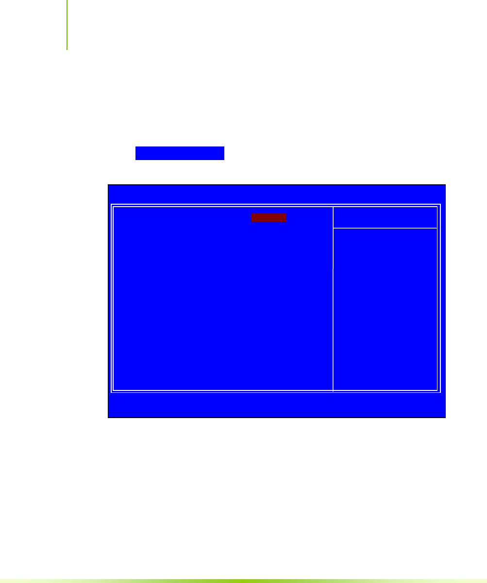
Advanced BIOS Features
Access the Advanced BIOS Features menu from the CMOS Utility
Setup screen. Use the Page Up and Page Down keys to scroll through
the options or press Enter to display the sub-menu. Use the
arrow keys to position the selector in the option you choose. To go
back to the previous menu, press Esc.
Note: The options that have associated sub-menus are designated by a `, which
precedes the option. Press Enter to display the sub-menus.
Figure 7. Advanced BIOS Features Menu
Note: Note that all data in white is for information only, data in yellow is changeable,
data in blue is non-changeable, and data in a red box is highlighted for
selection.
:Move Enter:Select +/-/PU/PD:Value F10:Save ESC:Exit F1:General Help
F
5: Previous Values F7:Defaults
` Removable Device Priority [Press Enter]
` Hard Disk Boot Priority [Press Enter]
` Network Boot Priority [Press Enter]
CPU Internal Cache [Enabled]
Quick Power On Self Test [Enabled]
First Boot Device [Removable]
Second Boot Device [CDROM]
Third Boot Device [Hard Disk]
Boot Other Device [Enabled]
Boot Up NumLock Status [On]
Security Option [Setup]
APIC Mode [Enabled]
MPS Version Control For OS [1.4]
Full Screen LOGO Show [Disabled]
Item Help
Main Level `
Select Removable Boot
Device Priority
Phoenix – AwardBIOS CMOS Setup Utility
Advanced BIOS F
e
atures

Configuring the BIOS
39

Installing and Configuring the NVIDIA nForce 650i Ultra Motherboard
40
Removable Device Priority
Use this option to select the priority for removable device startup.
Press Enter to see the list of removable devices in your system. Use
the arrow keys to go to the various devices. Then use the + or
– keys to move the device priority up or down in the list. To go
back to the previous menu, press Esc.
Hard Disk Boot Priority
Use this option to select the priority for HDD startup. Press Enter
to see the list of bootable devices in your system. Use the arrow
keys to go to the various devices. Then use the + or – keys to
move the device priority up or down in the list. To go back to the
previous menu, press Esc.
Network Boot Priority
Use this option to select the priority for network startup. Select
Network Boot Priority and press Enter to view available networks.
Use the arrow keys to go to the various devices. Then use the +
or – keys to move the device priority up or down in the list. To go
back to the previous menu, press Esc.
CPU Internal Cache
Use this option to enable or disable the CPU internal cache. Use the
Page Up and Page Down keys to scroll through the options or press
1.
F
loppy Disks
1. Network 0 : <description of network>
2. Network 1 : <descri
p
tion of network
>
1. Ch0. : ST3802110A
2. Bootable Ad
d
-
i
n Cards
Use the + and – keys to move the
priority of the device within the list

Configuring the BIOS
41
Enter to display the options in a sub-menu. Use the arrow keys
to position the selector in the option you choose.
Quick Power On Self Test
Enabling this option allows the system to skip certain test while
booting, which reduces the time needed to boot the system. Use the
Page Up and Page Down keys to toggle between Enable and Disable.
First/Second/Third Boot Device
Use this option to set the priority sequence of the devices booted at
power on. Use the Page Up and Page Down keys to scroll through
the options or press Enter to display the sub-menu. Use the
arrow keys to position the selector in the option you choose.
Boot Other Device
With the option set to Enable, the system boots from some other
device if the first/second/third boot devices fail.
Boot Up NumLock Status
This option allows you to select the power-on state of NumLock.
Select On to activate the keyboard NumLock when the system is
started. Select Off to disable the NumLock key.
First Boot Device
Removable ..... [ ]
Hard Disk ..... [ ]
CDROM ..... [ ]
Network ..... [ ]
Disabled ..... [ ]
:Move ENTER:Accept ESC:Abort

Installing and Configuring the NVIDIA nForce 650i Ultra Motherboard
42
Security Option
The Security Options allows you to require a password every time
the system boots or only when you enter setup. Select Setup to
require a password to gain access to the CMOS Setup screen. Select
System to require a password to access the CMOS Setup screen and
when the system boots.
APIC Mode
Use this function to enable or disable the Advanced Programmable
Interrupt Controller (APIC). If you disable this option, you also
disable the MPS Version Control for OS option.
MPS Version Control For OS
Use this function to select the Multi-Processor Specification (MPS)
version that BIOS passes to the operating system. Use the Page Up
and Page Down keys to scroll through the options.
Full Screen LOGO Show
This option allows you to enable or disable the display of the full-
screen logo when the system boots. Use the Page Up and Page Down
keys to toggle between Enable and Disable
Configuring the BIOS
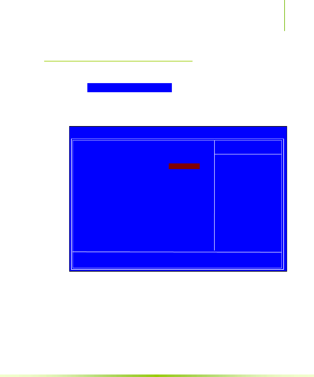
43
Advanced Chipset Features
Select Advanced Chipset Features from the CMOS Setup Utility
menu and press Enter to display the functions of the Advanced
Chipset Functions menu.
Figure 8. Advanced Chipset Features
:Move Enter:Select +/-/PU/PD:Value F10:Save ESC:Exit F1:General Help
F
5: Previous Values F7:Defaults
` System Clocks [Press Enter]
` FSB & Memory Config [Press Enter]
` CPU Configuration [Press Enter]
` System Voltages [Press Enter]
NVMEM memory test [Disable]
Load timing/voltage set [Press Enter]
Save timing/voltage set [Press Enter]
System BIOS Cacheable [Disabled]
HPET Function [Enable]
NVIDIA GPY Ex [Enable]
Item Help
Main Level `
Voltage control
Phoenix – AwardBIOS CMOS Setup Utility
Advanced Chipset Features
Installing and Configuring the NVIDIA nForce 650i Ultra Motherboard
44
System Clocks
Select System Clocks from the Advanced Chipset Features menu and
press Enter to display the System Clocks menu. From this menu,
you are able to specify frequency settings, HT multipliers, and
Spread Spectrum settings. Note that in Figure 9, all of the options
are listed. On the actual BIOS screen, you will need to scroll down
to see all the options.
Figure 9. System Clocks Menu
Note: Note that all data in white is for information only, data in yellow is changeable,
data in blue is non-changeable, and data in a red box is highlighted for
selection.
:Move Enter:Select +/-/PU/PD:Value F10:Save ESC:Exit F1:General Help
F
5: Previous Values F7:Defaults
Parameters Settings Current Valce
**Frequency Settings**
CPU Freq, MHz 2933.3 2933.3
FSB Reference Clock, MHz 1066.7 1066.7
CPU Multiplier [11 X] 11X
PCIe x16_1, MHz [Auto] 100
PCIe x16_3, MHz [Auto] 100
PCIe x16_2, MHz [Auto] 100
SPP<->MCP Ref Clock, MHz [Auto] 100
**HT Multiplier**
nForce SPP --> nForce MCP [5 x]
nForce SPP <-- nForce MCP [5 x]
**Spread Spectrum**
CPU Spread Spectrum [UP Spread]
HT Spread Spectrum Disabled
PCIe Spread Spectrum(SPP) [Auto]
PCIe Spread Spectrum(MCP) Disabled
SATA Spread Spectrum Disabled
Item Help
Main Level `
CPU frequency
multiplier.
CPU core clock
= FSB Ref Clock/4 *
CPU Multiplier
d
P
hoenix
–
AwardBIOS CMOS Setup Utility
System Clocks

Configuring the BIOS
45
Frequency Settings
CPU Freq, MHz
This value is set by the CPU Multiplier (value cannot be changed
by the user).
FSB Reference Clock. MHz
This value is set by the system (value cannot be changed by the
user). To change the FSB memory, and memory timing, go to the
FSB & Memory screen.
CPU Multiplier
This value changes the CPU Frequency value depending on the
value you choose. Use the Page Up and Page Down keys to scroll
through the options. The options are from 6 X through 60 X.
PCIe x16_1, MHz
Use the Page Up and Page Down keys to scroll through the
frequency options for the PCI Express Bus, Slot 1 (the black slot
closest to the CPU). Note that as you go higher in value, PCIe
Spread Spectrum(SPP) is disabled and cannot be changed from this
status.
PCIe x16_3, MHz
Use the Page Up and Page Down keys to scroll through the
frequency options for the PCI Express Bus, Slot 3 (the blue slot in
the middle).
PCIe x16_2, MHz
Use the Page Up and Page Down keys to scroll through the
frequency options for the PCI Express Bus, Slot 3 (the black slot
farthest from the CPU).
SPP<—>MCP Ref Clock, MHz
Use the Page Up and Page Down keys to scroll through the
frequency options for the reference clock between the SPP chip
and the MCP chip.

Installing and Configuring the NVIDIA nForce 650i Ultra Motherboard
46
HT Multiplier
nForce SPP — —> nForce MCP
Use the Page Up and Page Down keys to scroll through the HT
multiplier options and set the link speed from the SPP chip to the
MCP chip. Values are [1 x] through [5 x].
nForce MCP <— — nForce SPP
Use the Page Up and Page Down keys to scroll through the HT
multiplier options and set the link speed from the MCP chip to
the SPP chip. Values are [1 x] through [5 x].
Spread Spectrum
CPU Spread Spectrum
Use the Page Up and Page Down keys to scroll through the Spread
Spectrum options for the CPU. Option values are [Disabled],
[UP Spread], and [Center Spread].
HT Spread Spectrum
Disabled
PCIe Spread Spectrum (SPP)
Use the Page Up and Page Down keys to scroll through the Spread
Spectrum options for the SPP PCIe. Option values are [Disabled],
[UP Spread], and [Center Spread]. This option reverts to
Disabled and cannot be changed when the value for PCIe x16_1
exceeds 100MHz.
PCIe Spread Spectrum(MCP)
Disabled
SATA Spread Spectrum
Disabled

Configuring the BIOS
47
FSB & Memory Config
Select FSB & Memory Config from the Advanced Chipset Features
menu and press Enter to display the FSB & Memory Config menu.
This menu provides the means to set FSB and memory timing.
Figure 10. FSB & Memory Config Menu
:Move Enter:Select +/-/PU/PD:Value F10:Save ESC:Exit F1:General Help
F
5: Previous Values F7:Defaults
Parameters Settings Current Value
CPU Freq, MHz 2933.3 2933.3
CPU Multiplier 11X 11X
FSB – Memory Clock Mode [Auto]
x FSB (QDR), MHz Auto 1066.7
Actual FSB (QDR), MHz 1066.7
x MEM (DDR), MHz Auto 800.6
Actual MEM (DDR), MHz 800.0
` Memory Timing Setting [Press Enter]
Item Help
Main Level ``
“CPUOC MAX” realizes
the complete optimized
memory settings when
SLI-Ready memory is
installed
Optimized memory
settings by allowing
X% CPU overclocking
CPU overclocking may
require manual
overvolting of the CPU
to improve system
s
tability
Phoenix – AwardBIOS CMOS Setup Utility
FSB & Memory Config

Installing and Configuring the NVIDIA nForce 650i Ultra Motherboard
48
FSB and Memory Clock Mode
Use the Page Up and Page Down keys to scroll through the FSB
and Memory Clock Mode options. The options are:
¾ Auto
This is the optimal setting since it sets the FSB and memory
speeds automatically.
¾ Linked
When Link is selected, FSB (QDR), MHz is changed to
editable and the FSB speed can be entered manually. As the
FSB speed is changed, CPU Freq, MHz changes proportionally.
¾ Unlinked
When Unlink is selected, FSB (QDR), MHz and MEM (DDR),
MHz are changed to editable and the FSB and memory speeds
can be entered manually. As the FSB speed is changed, CPU
Freq, MHz changes proportionally.
FSB (QDR), MHz
Use the + or – keys to scroll through new values for the CPU
FSB frequency or type in a new value. Note that the Actual FSB
(QDR) reflects the actual frequency that takes effect on a reboot.
MEM (DDR), MHz
Use the + or – keys to scroll through new values for the memory
frequency or type in a new value. Note that the Actual MEM
FSB – Memory Clock Mode [Linked]
FSB (QDR), MHz [1067] 1066.7
Actual FSB (QDR), MHz 1066.7
MEM (DDR), MHz [1067] 800.6
Actual MEM (DDR), MHz 800.0
CPU Freq, MHz 2933.3 2933.3
CPU Multiplier 11X 11X
FSB – Memory Clock Mode [Linked]
FSB (QDR), MHz [1067] 1066.7
Actual FSB (QDR), MHz 1066.7
x MEM (DDR), MHz Auto 800.6
Actual MEM (DDR), MHz 800.0

Configuring the BIOS
49
(DDR) reflects the actual frequency that takes effect when the
system reboots.
Installing and Configuring the NVIDIA nForce 650i Ultra Motherboard
50
Memory Timing Setting
Press Enter to display the Memory Timing Setting menu. Use this
menu to set optimal timings or to manually enter timings.
¾ Optimal
Use the Page Up and Page Down keys to select Optimal.
Optimal prohibits you from manually setting any timing. All
timing is set for optimal performance.
:Move Enter:Select +/-/PU/PD:Value F10:Save ESC:Exit F1:General Help[
F5: Previous Values F7:Defaults
Parameters Settings Current Value
Memory Timing Setting [Optimal]
x tCL (CAS Latency) Auto(5) 5
x tRDC Auto(7) 5
x tRP Auto(7) 5
x tRAS Auto(23) 18
x Command Per Clock (CDM) Auto(2T) 1T
** Advanced Memory Settings **
x tRRD Auto(4) 3
x tRC Auto(28) 22
x tWR Auto(7) 5
x tWTR Auto(10) 9
x tREF Auto 6.1uS
Item Help
Main Level ``
Select [Expert] to
enter timings manually
Phoenix – AwardBIOS CMOS Setup Utility
Memory Timing Setting

Configuring the BIOS
51
¾ Expert
Use the Page Up and Page Down keys to select Expert. When
Expert is selected, all timing categories are enabled for manual
input. Note that you should set the value to Optimal to use
the manufacturers’ recommended values.
ª tCL: CAS# latency (options are 1 through 6).
ª tRDC: RAS#-to-CAS# Delay for Read/Write commands to
the same bank (options are 1 through 7).
ª tRP: Row Precharge time. This is the Precharge-to-Active
or Auto-to-Refresh of the same bank (options are 1 through
7).
ª tRAS: This is the minimum RAS# active time (options are
1 through 31).
ª Command Per Clock: This is the command timing setting
on a per clock unit basis (options are 1T and 2T).
ª tRRD: RAS#-to-RAS# delay of different banks (options are 1
through 15).
ª tRC: RAS#-to-RAS# or auto refresh time of the same bank
(options are 1 through 31).
ª tWR: The Write recovery time (options are 2 through 7).
ª tWTR: This is the minimum write-to-read delay with the
same chip selected (options are 1 through 10).
Parameters Settings Current Value
Memory Timing Setting [Expert]
tCL (CAS Latency) [Auto(5)] 5
tRDC [Auto(7)] 5
tRP [Auto(7)] 5
tRAS [Auto(23)] 18
Command Per Clock (CDM) [Auto(2T)] 1T
** Advanced Memory Settings **
tRRD [Auto(4)] 3
tRC [Auto(28)] 22
tWR [Auto(7)] 5
tWTR [Auto(10)] 9
tREF [Auto] 6.1uS
Installing and Configuring the NVIDIA nForce 650i Ultra Motherboard
52
ª tREF: This is the DRAM refresh rate (options are Auto,
7.8uS, and 3.9uS).
CPU Configuration
Select CPU Configuration from the Advanced Chipset Features menu
and press Enter to display the CPU Configuration menu.
Figure 11. CPU Configuration Menu
Limit CPUID MaxVal
Use this function to enable the set limit of the CPUID MaxVal to
3. Set to Disable for Win XP.
CPU Thermal Control
Use this function to enable or disable TM1 and TM2 support.
Options are:
¾ Disable
Disable support for TM1 and TM2.
:Move Enter:Select +/-/PU/PD:Value F10:Save ESC:Exit F1:General Help
F
5: Previous Values F7:Defaults
Limit CPUID MaxVal [Disabled]
x Intel SpeedStep Disabled
CPU Thermal Control [Disabled]
C1E Enhanced Halt State [Enabled]
Execute Disable Bit [Enabled]
Virtualization Technology [Enabled]
CPU Core 0 Enabled
CPU Core 1 [Enabled]
x CPU Core 2 Disabled
x CPU Core 3 Disabled
Item Help
Main Level ``
Set linit CPUID MaxVal
to 3, should be
“Disabled” for WinXP
Phoenix – AwardBIOS CMOS Setup Utility
CPU Configuration

Configuring the BIOS
53
¾ TM1 Only
The CPU is thermally throttled by cutting active processor
clock cycles.
¾ TM2 Only
Thermal throttling is achieved by reducing the CPU multiplier
and CPU core voltage.
¾ TM1 & TM2
Enables support for both TM1 and TM2.
C1E Enhanced Halt State
Enabled, this function reduces the CPU power consumption when
the CPU is idle. Idle occurs when the operating system issues a
halt instruction.
Execute Disable Bit
When this function is disabled, it forces the XD feature flag to
always return to zero (0).
Virtualization Technology
When this function is enabled, it allows a VMM to utilize the
additional hardware capabilities provided by Intel Virtualization
Technology.
CPU Core 1
This function allows you to enable or disable CPU Core.
System Voltages[NC1]
Select System Voltages from the Advanced Chipset Features menu
and press Enter to display the System Voltages menu.
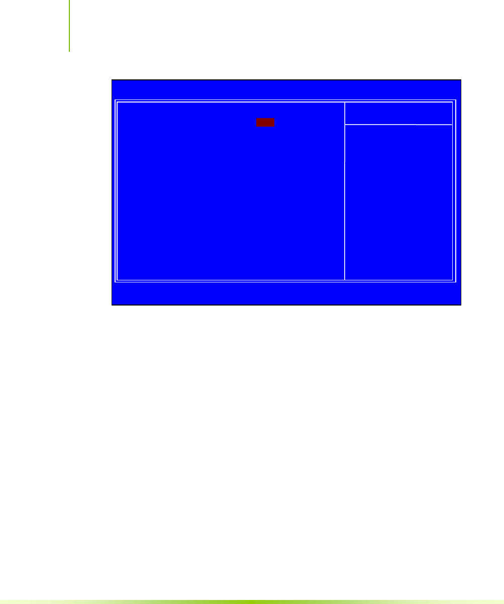
Installing and Configuring the NVIDIA nForce 650i Ultra Motherboard
54
Figure 12. System Voltages Menu
CPU Core
Use the Page Up and Page Down keys to scroll through the voltages
or select [Auto] to automatically set the voltage level for the CPU
Core.
Memory
This function defines the voltage level for the DRAM. Use the
Page Up and Page Down keys to select a voltage or select [Auto] to
automatically set the voltage.
nForce SPP
This function defines the core voltage level for the NVIDIA
nForce SPP chip. Use the Page Up and Page Down keys to select a
voltage (1.20V, 1.30V, 1.40V, 1.50V) or select [Auto] to
automatically set the voltage.
CPU FSB
This function defines the CPU front-side bus (FSB) voltage level
(1.20V to 1.40V). Use the Page Up and Page Down keys to select a
:Move Enter:Select +/-/PU/PD:Value F10:Save ESC:Exit F1:General Help
F
5: Previous Values F7:Defaults
Item Help
Main Level ``
Voltage level for CPU
Core (CPU VID)
Phoenix – AwardBIOS CMOS Setup Utility
System Voltages
Parameters Settings Current Value
CPU Core [Auto] 1.28
Memory [Auto] 1.85V
nForce SPP [Auto] 1.20V
CPU FSB [Auto] 1.20V

Configuring the BIOS
55
voltage or select [Auto] to automatically set the voltage.
NVMEM Memory Test
This function defines whether you run the NVIDIA memory testing
module during POST. The options are Fast, Medium, Slow, and
Disable.
Load Timing/Voltage Set
This function loads the system voltages and timing settings that were
defined in the System Voltages menu. You can set up to four profile
settings using the Save timing/voltage set function.
There are four profile options that can be loaded. The default setting
is Auto for all settings. Press Enter to see the options.
Load timing/voltage set
Press Enter to Exit ..... [ ]
Select Profile 1 ..... [ ]
Select Profile 2 ..... [ ]
Select Profile 3 ..... [ ]
:Move ENTER:Accept ESC:Abort

Installing and Configuring the NVIDIA nForce 650i Ultra Motherboard
56
Save Timing/Voltage Set
This function saves the system voltages and timing settings that were
defined in the System Voltages menu. There are four profile options
that can be loaded. The default setting is Auto for all settings. Press
Enter to see the options.
System BIOS Cacheable
This function allows you to enable or disable caching the system
BIOS.
HPET Function
This function allows you to enable or disable the High Precision
Even Timer (HPET). When Enabled, HPET is used as the timing
hardware for multimedia and other time-sensitive application. When
HPET is Disabled, the APIC timer is used.
NVIDIA GPU Ex
To enable or disable this function you need to have the NVIDIA®
ForceWare® graphics driver with NVIDIA EX support. When
enabled, the system uses the optimized NVIDIA EX graphics driver.
Save timing/voltage set
Press Enter to Exit ..... [ ]
Select Profile 1 ..... [ ]
Select Profile 2 ..... [ ]
Select Profile 3 ..... [ ]
:Move ENTER:Accept ESC:Abort
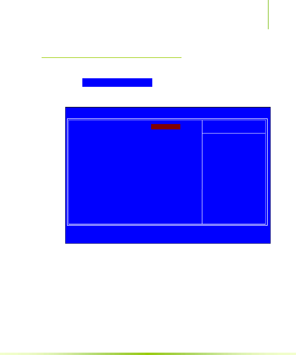
Configuring the BIOS
57
Integrated Peripherals Menu
Select Integrated Peripherals from the CMOS Setup Utility menu
and press Enter to display the Integrated Peripherals menu.
Figure 13. Integrated Peripherals Menu
:Move Enter:Select +/-/PU/PD:Value F10:Save ESC:Exit F1:General Help
F5: Previous Values F7:Defaults
` IDE Function Setup [Press Enter]
` RAID Config [Press Enter]
` USB Config [Press Enter]
` MAC Config [Press Enter]
IEEE1394 controller [Auto]
HD Audio [Auto]
IDE HDD Block Mode [Enabled]
Onboard FDC Controller [Enabled]
Onboard Serial Port 1 [3FB/IRQ4]
Item Help
Main Level `
Phoenix – AwardBIOS CMOS Setup Utility
Integrated Peripherals

Installing and Configuring the NVIDIA nForce 650i Ultra Motherboard
58
OnChip IDE Channel0 [Disabled]
x Primary Master PIO Auto
x Primary Slave PIO Auto
x Primary Master UDMA Auto
x Primary Slave UDMA Auto
IDE DMA transfer access [Enabled]
Serial-ATA Controller [All Enabled]
IDE Prefetch Mode [Enabled]
IDE Function Setup
Press Enter to display the IDE Function Setup menu.
OnChip IDE Channel0
Use this function to
enable or disable the
onchip IDE Channel0.
When disabled, the
Primary Master/Slave
functions are changed to
Auto and cannot be changed.
Primary Master/Slave PIO
When OnChip IDE Channel0 is set to [Enabled], you can select
a mode for the primary Master and Slave PIO. Select from Auto,
or Mode 1 through Mode 4.
Primary Master/Slave UDMA
When OnChip IDE Channel0 is set to [Enabled], you can
disable the primary Master and Slave UDMA or set it to [Auto].
IDE DMA transfer access
Use this function to enable or disable IDE DMA transfer access.
Serial-ATA Controller
This function allows you to enable specific SATA controllers,
enable all controllers, or disable all controllers. The options
available are [SATA-0], [SATA-0+1], [Enable All], and
[Disabled].
IDE Prefetch Mode
Use this function to enable or disable the IDE Prefetch mode.
OnChip IDE Channel0 [Enabled]
Primary Master PIO [Auto]
Primary Slave PIO [Auto]
Primary Master UDMA [Auto]
Primary Slave UDMA [Auto]
IDE DMA transfer access [Enabled]
Serial-ATA Controller [All Enabled]
IDE Prefetch Mode [Enabled]

Configuring the BIOS
59
RAID Enable [Disabled]
x SATA 0 Primary RAID Disabled
x SATA 0 Secondary RAID Disabled
x SATA 1 Primary RAID Disabled
x SATA 1 Secondary RAID Disabled
x SATA 2 Primary RAID Disabled
x SATA 2 Secondary RAID Disabled
OnChip USB [Disabled]
x USB Keyboard Support Enabled
x USB Mouse Support Enabled
RAID Config
Press Enter to display the RAID Config menu.
RAID Enable
Use this function to
enable or disable RAID.
When RAID is set to
[Disabled], all SATA
functions are changed to
Disabled and cannot be
changed.
SATA x Primary/Secondary
When RAID Enable is set to [Enabled], you can enable or
disable the various SATA functions.
USB Config
Press Enter to display the USB Config menu.
OnChip USB
Use this function to
enable specific versions of
the USB or disable the onchip USB. When the onchip USB is set
to [Disabled], the keyboard and mouse support functions are set
OnChip USB [Enabled]
USB Keyboard Support [Disabled]
USB Mouse Support [Disabled]
RAID Enable [Enabled]
SATA 0 Primary RAID [Disabled]
SATA 0 Secondary RAID [Disabled]
SATA 1 Primary RAID [Disabled]
SATA 1 Secondary RAID [Disabled]
SATA 2 Primary RAID [Disabled]
SATA 2 Secondary RAID [Disabled]

Installing and Configuring the NVIDIA nForce 650i Ultra Motherboard
60
to Enabled and cannot be changed. Versions that can be selected
are [V1.1+V2.0] or [V1.1].
USB Keyboard/Mouse Support
Use these function to enable or disable the onchip WSB support of
the keyboard and/or mouse.
MAC Config
Press Enter to display the MAC Config menu.
MACx LAN
Use these functions to set the MAC0 and/or MAC1 LANs to
Auto or disable their functions.
HD Audio
This function on the Integrated Peripherals menu allows you to
enable or disable the hard disk audio function.
IDE HDD Block Mode
Using this function on the Integrated Peripherals menu allows your
IDE hard drive needs to support block mode. Select [Enabled] to
automatically detect the optimal number of block read/writes per
sector the drive can support. Select [Disabled] if your drive does
not support block mode.
Onboard FDC Controller
This function on the Integrated Peripherals menu allows you to
enable or disable the onboard FDC controller function.
MAC0 LAN [Enabled]
MAC1 LAN [
D
isabled
]

Configuring the BIOS
61
Onboard Serial Port 1
This function on the Integrated Peripherals menu allows you to
select the onboard serial port 1 function. Options are [3F8/IRQ4],
[2E8/IRQ3], [3E8/IRQ4], [Auto], and [Disabled].
Power Management Setup
Menu
Select Power Management Setup from the CMOS Setup Utility menu
and press Enter to display the Power Management Setup menu.
Figure 14. Power Management Setup Menu
:Move Enter:Select +/-/PU/PD:Value F10:Save ESC:Exit F1:General Help
F5: Previous Values F7:Defaults
ACPI function [Enabled]
APCI Suspend Type [S1&S3]
Soft-Off by PBTN [Instant-Off]
WOL(PME#) From Soft-Off [Disabled]
Power-on by Alarm [Disabled]
x Day of Month Alarm 0
x Time (hh:mm:ss) Alarm 0 : 0 : 0
POWER ON Function [BUTTON ONLY]
x KB Power ON Password Enter
x Hot Key Power On Ctrl-F1
Item Help
Main Level `
Phoenix – AwardBIOS CMOS Setup Utility
Power Management Setup

Installing and Configuring the NVIDIA nForce 650i Ultra Motherboard
62
ACPI Function
This function on the Power Management Setup menu allows you to
enable or disable the ACPI function.
ACPI Suspend Type
This function on the Power Management Setup menu allows you to
select an ACPI Suspend Type. Types to select from are [S1&S3],
[S1(POS)], and [S3(STR)].
Soft-Off by PBNT
This function on the Power Management Setup menu allows you to
set Soft-Off by PBNT to [Instant-Off] or [Delay 4 Sec].
WOL(PME#) From Soft-Off
This function on the Power Management Setup menu allows you to
enable or disable WOL(PMW#) from soft-off.
Power On by Alarm
This function on the Power Management Setup menu allows you to
enable or disable the Power-on by alarm function. Set to [Disable]
to prevent power-on by alarm. When set to [Enable], you can
manually put in the day of the month and the time of the alarm.
To enter a day or time, use the Page Up and Page Down keys to
scroll through numbers or enter the number using the keyboard
number or the + and – keys.
Power-on by Alarm [Disabled]
Day of Month Alarm [ 0]
Time (hh:mm:ss) Alarm [0 : 0 : 0]

Configuring the BIOS
63
POWER ON Function
This function on the Power Management Setup menu allows you to
define the power-on function. Options for this function are:
BUTTON ONLY
Keyboard 98
Password
When [Password] is selected, the KB Power ON Password
function is enabled so that you must enter a password.
POWER ON Function [Password]
KB Power ON Password [Enter]
xHot Ke
y
Power On Ctrl
-
F
1
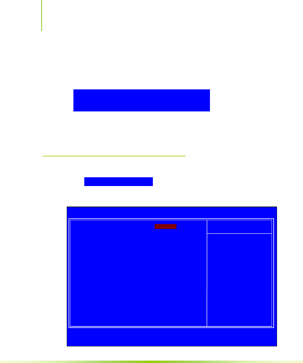
Installing and Configuring the NVIDIA nForce 650i Ultra Motherboard
64
Hot Key Power On
When [Hot Key] is selected, the Hot key Power On function is
enabled so that you must select a keyboard key as the hot key.
To select a hot key use Ctrl+F1 though Ctrl+F12.
Mouse Left
Mouse Right
Any Key
PnP/PCI Configuration Menu
Select PnP/PCI Configuration from the CMOS Setup Utility menu
and press Enter to display the PnP/PCI Configuration menu.
:Move Enter:Select +/-/PU/PD:Value F10:Save ESC:Exit F1:General Help
F5: Previous Values F7:Defaults
Init Display First [PCI Slot]
Reset Configuration Data [Disabled]
Resources Controlled By [Auto(ESCD)]
x IRQ Resources Press Enter
** PCI Express relative items **
Maximum Payload Size [4096]
Item Help
Main Level `
POWER ON Function [Hot key]
x KB Power ON Password Enter
Hot Key Power On [Ctrl-F1]
Phoenix – AwardBIOS CMOS Setup Utility
PnP/PCI Configuration

Configuring the BIOS
65
Figure 15. PnP/PCI Configuration Menu
Init Display First
This function on the PnP/PCI Configuration menu allows you to
define if the initial display is in the PCI slot or in the PCI Express
slot. Options are
[PCI Slot] and [PCIEx].
Reset Configuration Data
This function on the PnP/PCI Configuration menu allows you to
enable or disable the resetting of Extended System Configuration
Data (ESCD) when you exit Setup. Set this to [Enabled] if you
have installed a new add-on and the system reconfiguration has
caused a serious conflict that prevents the OS from booting. The
default setting is [Disabled].
Resources Controlled By
This function on the PnP/PCI Configuration menu allows you to
define if the BIOS can automatically configure all the boot and plug-
and-play compatible devices or if you can manually select IRQ,
DMA, and memory base address fields. Select [Auto(ESCD)] if you
want the BIOS to automatically populate these fields. If you select
[Manual] so you can assign the resources, IRQ Resources is
enabled for input.
Resources Controlled By [Manual)]
IR
Q
R
esou
r
ces
[
Pr
ess
En
te
r
]
Resources Controlled By [Auto(ESCD)]
x IRQ Resources Press Enter

Installing and Configuring the NVIDIA nForce 650i Ultra Motherboard
66
IRQ Resources
To enable this field for input, set Resources Controlled By to
[Manual]. With this field enabled, press Enter to see options.
Use Legacy ISA for devices compliant with the original PC AT Bus
specification. Use PCI/ISA PnP for devices compliant with the plug-
and-play standard, whether designed for PCI or ISA Bus architecture.
PCI/VGA Palette Snoop
This function on the PnP/PCI Configuration menu allows you to
enable or disable the Palette Snoop function.
Maximum Payload Size
This function on the PnP/PCI Configuration menu allows you to set
the maximum TLP payload size (in bytes) for the PCI Express
devices. Use the Page Up and Page Down keys to scroll through sizes
or enter the number using the keyboard numbers or use the + and
– keys to go up and down the list of sizes.
IRQ-5 assigned to [PCI Device]
IRQ-9 assigned to [Reserved]
IRQ-10 assigned to [PCI Device]
IRQ-11 assigned to [PCI Device]
IRQ-14 assigned to [PCI Device]
IRQ-15 assigned to [PCI Device]
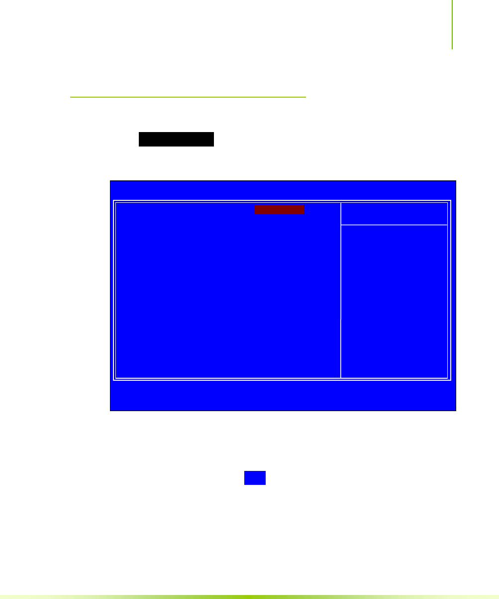
Configuring the BIOS
67
System Monitor Menu
Select System Monitor from the CMOS Setup Utility menu and press
Enter to display the System Monitor menu.
Figure 16. System Monitor Menu
All of the values shown in Blue are dynamic and change as the
speed and voltages of the various components change with system
usage.
:Move Enter:Select +/-/PU/PD:Value F10:Save ESC:Exit F1:General Help
F5: Previous Values F7:Defaults
` Dynamic Fan Control [Press Enter]
CPU 47ºC/ 117ºF
CPU Core 1.28V
CPU FSB 1.19V
Memory 1.81V
+3.3V 3.16V
+3.3V Dual 3/16V
+12V 11.92V
+5V 4.99V
+Vbat 3.00V
CPU Fan Speed 4272 RPM
Aux Fan Speed 4891 RPM
nForce Fan Speed 0 RPM
Chassis Fan Speed 0 RPM
Chassis Fan2 Speed 0 RPM
Item Help
Main Level `
Phoenix – AwardBIOS CMOS Setup Utility
S
ystem Monitor

Installing and Configuring the NVIDIA nForce 650i Ultra Motherboard
68
Dynamic Fan Control
Press Enter to display the Dynamic Fan Control menu.
Use this menu to control the speed of the various fans on the
motherboard. Set CPU fan speed to [SmartFan] when you want
the speed of the fans automatically controlled based on temperature.
To set the fan speed to a constant rate, select [Manual] and then
enter the speed from 0% to 100%.
Set the desired speed for the Aux, nForce, and Chassis fans from 0%
to 100%. The system defaults to 100%.
CPU Fan Speed Control [SmartFan]
If temp > 70ºC, Set Fan Speed 100%
If temp < 30ºC, Set Fan Speed 0%
x Manual Fan Speed, % 100
AUX Fan Speed Control, % [100]
nForce Fan Speed Control, % [100]
Chassis Fan Speed Control, % [100]

69
Software Installation
Note: It is important to remember that before installing the driver CD that is shipped
in the kit, you need to load your operating system. The motherboard
supports Windows XP 32bit and 64bit and is Vista-capable.
The kit comes with a CD that contains utility drivers and additional
NVIDIA software.
The CD that has been shipped with your NVIDIA motherboard
contains the following software and drivers:
NVIDIA nForce drivers
RealTek Audio drivers
Microsoft DirectX 9.0C
NVIDIA nTune
Adobe Acrobat Reader
NVIDIA MediaShield RAID Manager
NVIDIA Networking (FirstPacket)
Norton Internet Security

Installing and Configuring the NVIDIA nForce 650i Ultra Motherboard
70
Windows XP Drivers Install
Note: When installing the graphics drivers, the resolution defaults to the lowest
setting (typically 800 x 600), making your display very large. Adjust
accordingly.
1. Insert the NVIDIA nForce 650i Ultra installation CD for the
graphics drivers included in the kit.
Note: If you have multiple graphics cards installed, you will be asked multiple times
for all events once the drivers are installed.
2. Run setup.exe.
Depending on your system setup, the install disk may automatically
run the install setup.exe. If it does not run, go to My Computer
and click on the CD to open.
Partner
Update this section with your setup.exe process.
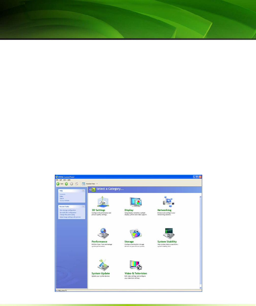
71
Using the
NVIDIA Software
This section describes how to configure the following NVIDIA
software that is included on the CD in the kit from the NVIDIA
Control Panel:
NVIDIA Monitor
Performance (NVIDIA nTune)
Storage (NVIDIA MediaShield RAID Manager)
Networking (NVIDIA FirstPacket)
System Update
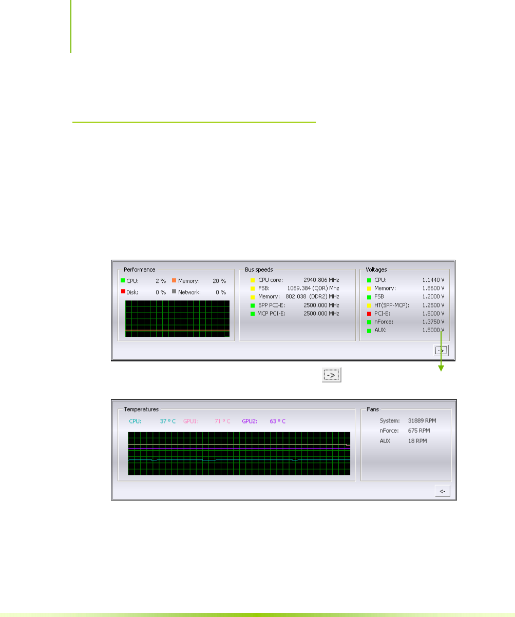
Installing and Configuring the NVIDIA nForce 650i Ultra Motherboard
72
Figure 17. NVIDIA Control Panel, Select a Category
NVIDIA Monitor
The NVIDIA Monitor application can be used at any time with any
applications to view the real-time status of various system
components. To display the NVIDIA Monitor, select Start¾All
Programs¾NVIDIA Corporation¾NVIDIA Monitor. This display shows the
performance (usage) of the CPU, disk, memory, and network. It also
monitors the Bus speeds and voltages.
To view temperatures and fans, click the button.
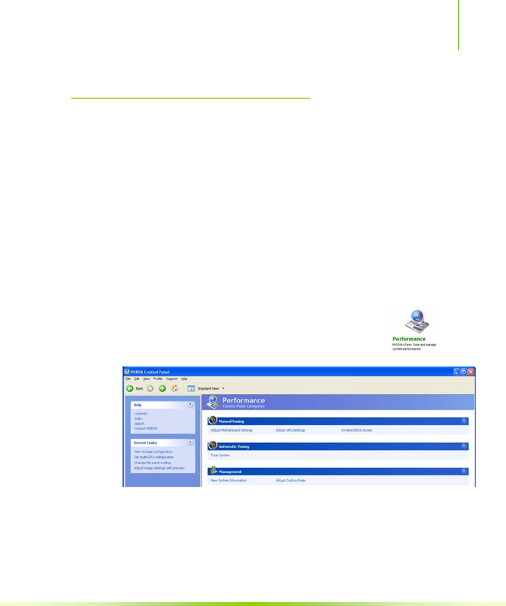
Using NVIDIA Software
73
NVIDIA nTune 5.0
The Performance category is used to configure and manage NVIDIA
nTune. The NVIDIA nTune program is a full-featured application
for accessing, monitoring, and adjusting your system components
(including bus speeds and voltages) with clear, user-friendly control
panels.
Overclock your system for the highest performance, or underclock it
for a nearly silent operation. All changes are performed within the
Microsoft Windows interface, enabling full functionality without the
need to make changes in the BIOS and reboot your system.
Use the following procedure to access nTune:
1. From the desktop, select Start¾All Programs¾NVIDIA
Corporation¾NVIDIA Control Panel.
2. Select Performance to display Performance Control Panel
Categories.
Figure 18. Performance Control Panel Categories (nTune)
The Performance menu provides the following options:
¾ Manual Tuning
ª Adjust motherboard settings
ª Adjust GPU settings
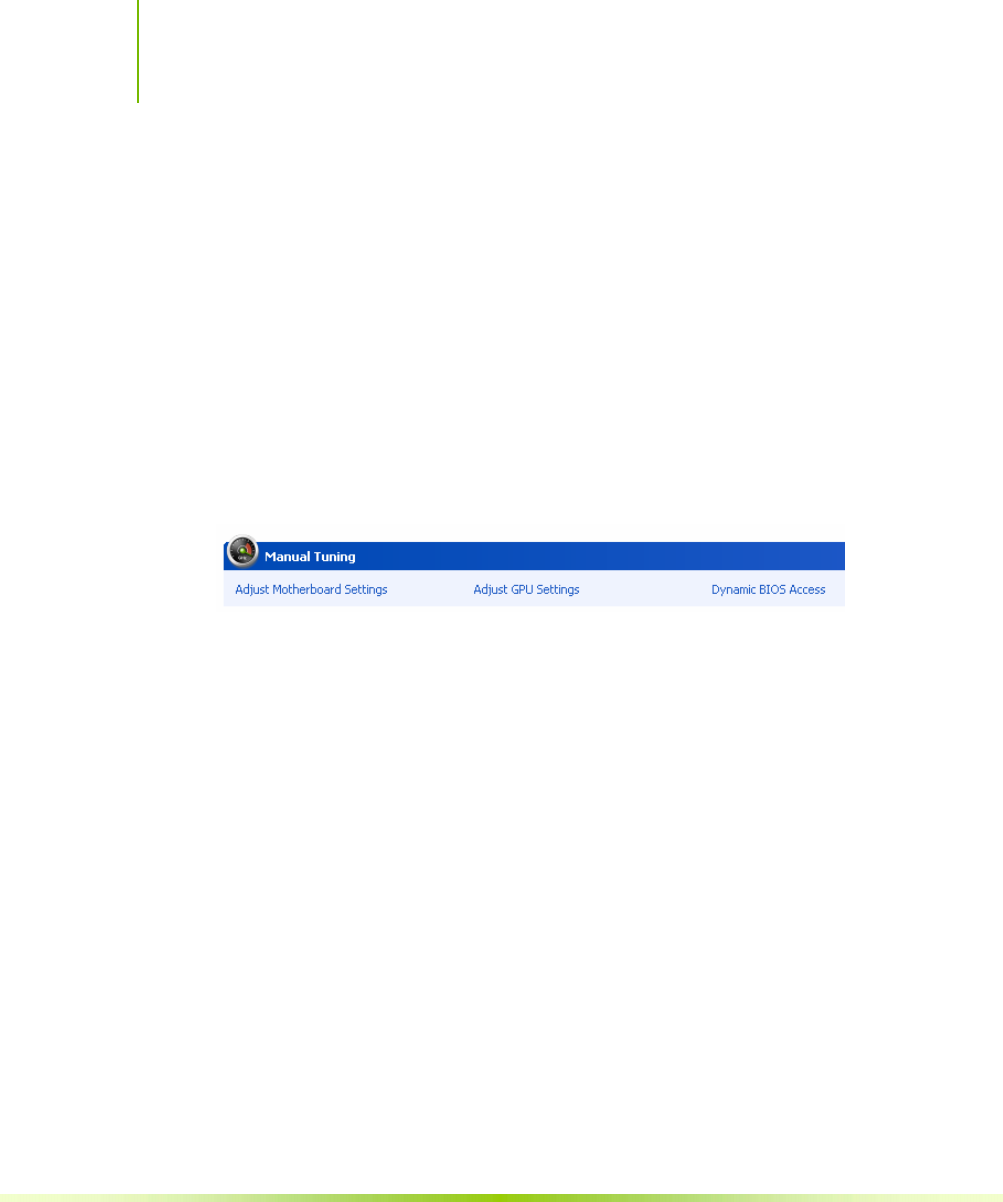
Installing and Configuring the NVIDIA nForce 650i Ultra Motherboard
74
ª Dynamic BIOS access
¾ Automatic Tuning
ª Tune system
¾ Management
ª View system information
ª Adjust custom rules
Manual Tuning
The Manual Tuning option provides the ability to adjust
motherboard settings, adjust CPU settings, and make changes to the
BIOS.
Adjust Motherboard Settings
The controls in the Adjust Motherboard Settings screen let you adjust
the performance of the system clocks, system voltages, memory
controller timings, and system fans. By manually adjusting these
speeds you are able to either increase performance for gaming, or
reduce performance to conserve power and create a quieter
environment.
Figure 19 shows the Adjust Motherboard Settings screen. Note that
as you pass the cursor over the various adjustments, notes display at
the bottom of the screen to explain each setting.
The number to the right of the slider is the new bus speed that will
be applied. Make adjustments by using the mouse to drag the slider.
All changes take effect immediately after selecting Apply; however,
these setting only remain active for the current Windows session.
This allows you to safely return to Windows if a crash occurs, with
no possibility of boot issues since the changes are not made directly
to the BIOS settings.
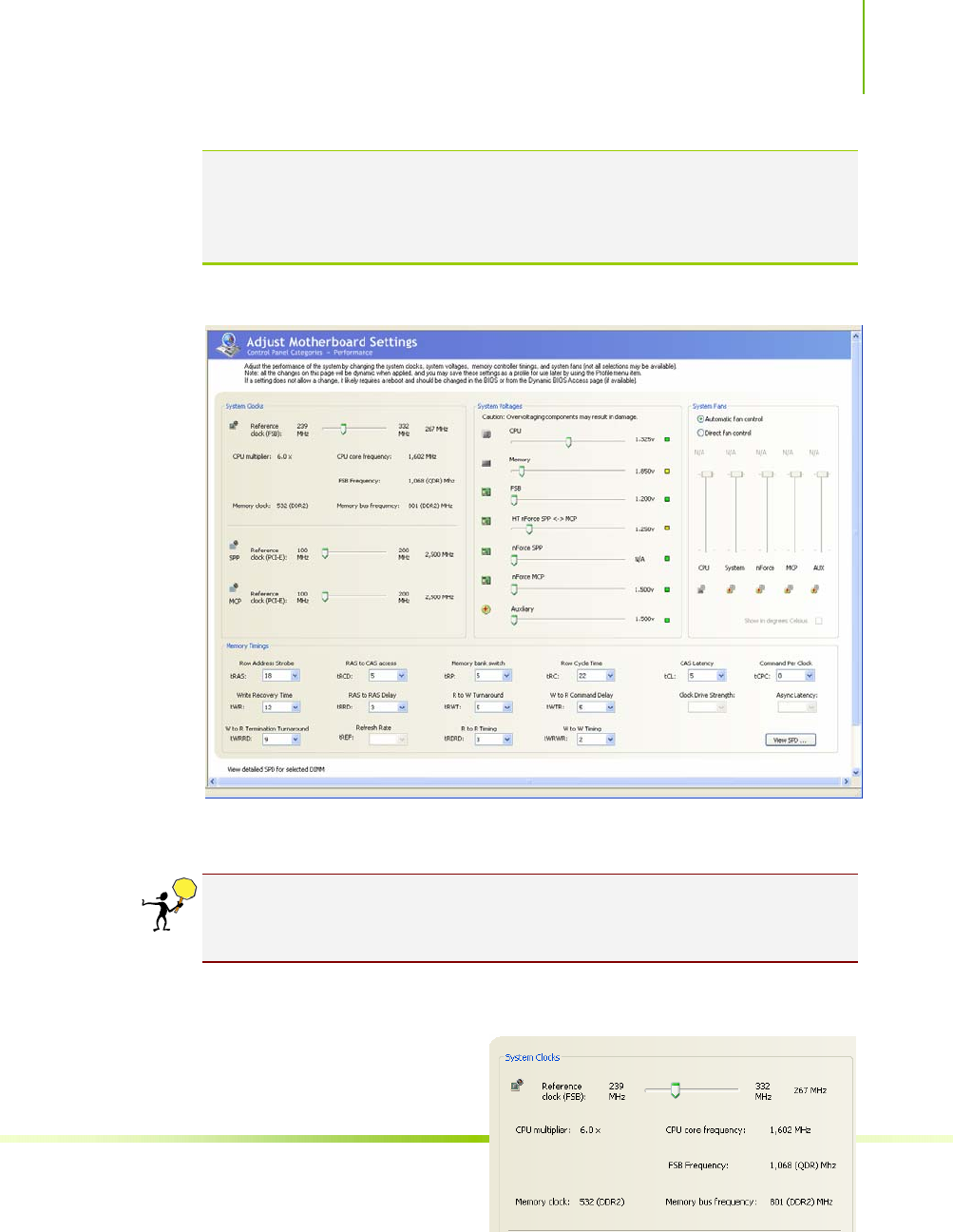
Using NVIDIA Software
75
Note: All changes on Adjust Motherboard Settings are dynamically made when you
apply them, and only remain active for the current Windows session. You can
save these settings as a profile for use later by using the Profile menu item. If
a setting does not allow a change, it probably requires a reboot and should
be changed in the BIOS or from the Dynamic BIOS Access page (if available).
Figure 19. Adjust Motherboard Settings (nTune)
CAUTION: Increasing the voltage or the clock speed of a component may
void its warranty due to exceeding recommended specifications. NVIDIA
and the board manufacturer are not responsible for damage that may occur
when component tolerances are exceeded.
System Clocks
This section of the Adjust
Motherboard Settings allows
you to adjust the reference
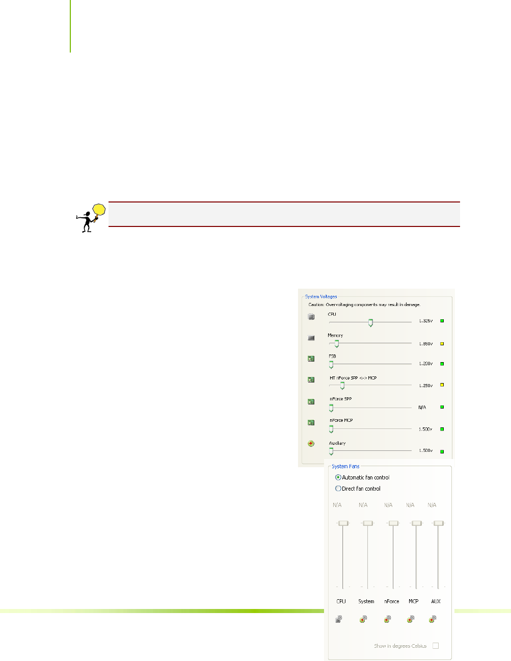
Installing and Configuring the NVIDIA nForce 650i Ultra Motherboard
76
clocks for the FSB, the SPP PCI Express, and the MCP PCI Express.
Note that as you change the slider for the FSB reference clock, the
CPU core frequency, the FSB Frequency and the memory bus
frequency are dynamically changed.
System Voltages
CAUTION: Overvoltaging any component can result in damage.
In this section of the Adjust Motherboard Settings you must
understand what you are changing. Overvoltaging any of the
components can result in damage
to the components. From this
menu, you can adjust the following
voltages:
CPU
Memory
FSB
HyperTransport SSP MCP
nForce SPP
nForce MCP
Auxiliary
Always note the color of the
indicator square to the right of each
slider. Green indicates the voltage is
within range and will not damage any
components. Yellow means to proceed
with caution; you are no longer in the
safe range. If the indicator square is red,
you are possible overvoltaging the
component and could be causing damage.

Using NVIDIA Software
77
System Fans
This section of the Adjust Motherboard Settings menu allows you to
control the CPU, System, nForce, MCP, and the auxiliary fans. You
can either set all the fans to automatic control or you can manually
control each fan.
When in manual control, you can specify to show the temperatures
in Celsius or Fahrenheit.

Installing and Configuring the NVIDIA nForce 650i Ultra Motherboard
78
Memory Timing
This section of the Adjust Motherboard Settings allows you to adjust
various memory timings and cycles.
Row Address Strobe
Adjusts the minimum RAS active time. This is the amount of time
between a row being activated by Precharge and deactivated. A
row cannot be deactivated until tRAS has completed. The lower
this value, the faster the performance. However, if it is set too low
it can cause data corruption by deactivating the row to soon.
Adjustable from 1 to 63.
Write Recovery Time
Memory timing that determines the delay between a write
command and a Precharge command is set to the same bank of
memory. Adjustable from 1 to 15.
W to R Termination Turnaround
The Write-to-Read time is the number of clock cycles between the
last write data pair and the subsequent READ command to the
same physical block. Adjustable from 1 to 15.
RAS to CAS access
The RAS-to-CAS access (tRCD) is the amount of time in cycles for
Clicking on View SPD… displays a
memory information window. This is
for information only and is not editable.
When you select an option, information explaining
the selection is displayed in the area below the
Memory Timing box.

Using NVIDIA Software
79
issuing an active command and the read/write commands.
Adjustable from 1 to 15.

Installing and Configuring the NVIDIA nForce 650i Ultra Motherboard
80
RAS to RAS Delay
The RAS-to-RAS delay (tRRD) is the is the amount of cycles it
takes to activate the next bank of memory (this is the opposite of
tRAS). The lower the timing the better the system performance.
However, this scenario can cause instability. Adjustable from 1 to
15.
Refresh Rate
This value is filled in by the system and can not be changed by
the user.
Memory bank switch
The row Precharge time (tRP) is the minimum time between active
commands and the read/writes of the next bank on the memory
module. Adjustable from 1 to 15.
R to W Turnaround
The Read-to-Write turnaround (tRWT) is a the amount of cycles
for the command to be executed when a Write command is
received. Adjustable from 1 to 15.
R to R Timing
the Read-to-Read time (tRDRD) is the number of clock cycles
between the last read and the subsequent READ command to the
same physical bank. Adjustable from 1 to 15.
Row Cycle Time
The Row Cycle Time is the minimum time in cycles it take a row
to complete a full cycle. This can be determined by
tRC=tRAS+tRP. If this value is set too short, it can cause
corruption of data. If this value is set too high, it causes a loss in
performance but an increase in stability. Adjustable from 1 to 63
cycles
W to R Command Delay
The Write-to-Read (tWRD) command delay is the amount of cycles
required between a valid write command and the next read
command. A lower cycle time results in better performance but is
can instability. Adjustable from 0 to 6 cycles.
W to W Timing
The Write-to-Write (tWRWR) timing is the number of clock cycles

Using NVIDIA Software
81
between the last write and the subsequent Write command to the
same physical bank. Adjustable from 2 to 15 cycles.
CAS Latency
The CAS Latency (tCL) is the time (in number of clock cycles)
that elapses after the memory controller sends a request to read a
memory location and before the data is sent to the module's
output pins. The value shown cannot be changed.
Clock Drive Strength
This value is filled in by the system and can not be changed by
the user.
Command Per Clock
The Command Per Clock (tCPC) sets the Command Rate for the
memory controller. The value shown cannot be changed
Async Latency
This value is filled in by the system and can not be changed by
the user.
Adjust GPU Settings
Use this interface to adjust the graphics processing unit (GPU) on
your video card(s). You can override the shipped clock frequencies of
your GPU and GPU memory and set the GPU fan speed. Increasing
the clock speeds increases your GPU performance and may require
adjusting cooling to maintain the same level of reliability.
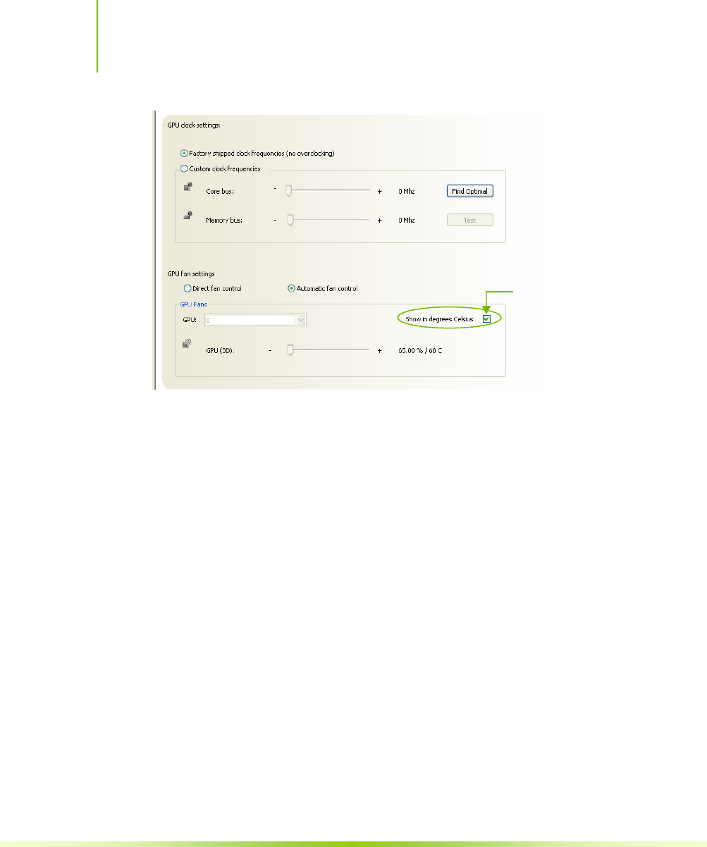
Installing and Configuring the NVIDIA nForce 650i Ultra Motherboard
82
Figure 20. Adjust GPU Settings (nTune)
When this option is
checked, all
temperatures are shown
in Celsius. When this
option is not check,
temperatures are shown
in Fahrenheit.
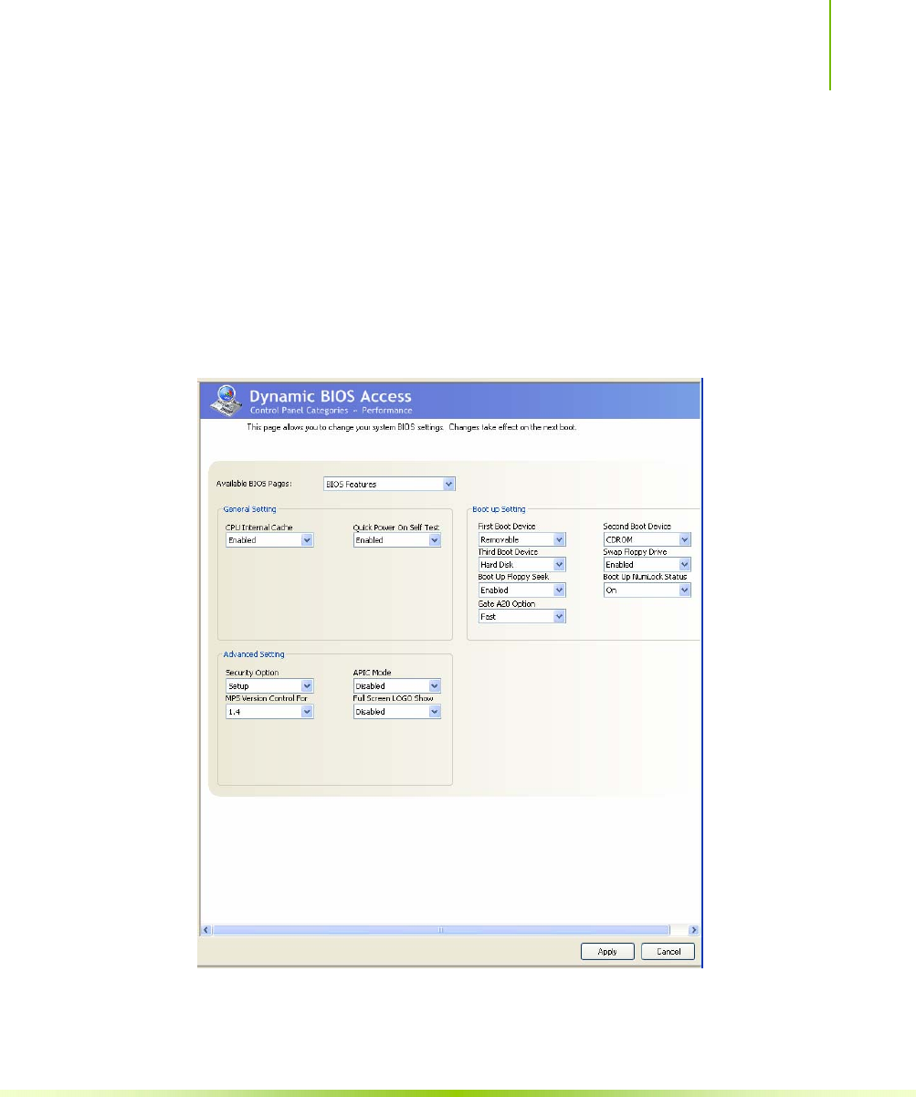
Using NVIDIA Software
83
Dynamic BIOS Access
Dynamic BIOS Access allows you to change some of your system
BIOS settings. The changes do not go into effect until you reboot
your system. Since these changes are made to actual BIOS settings in
the CMOS, the settings remain active until you change them again
or restore the CMOS to the default settings.
Figure 21. Dynamic BIOS Access (nTune)
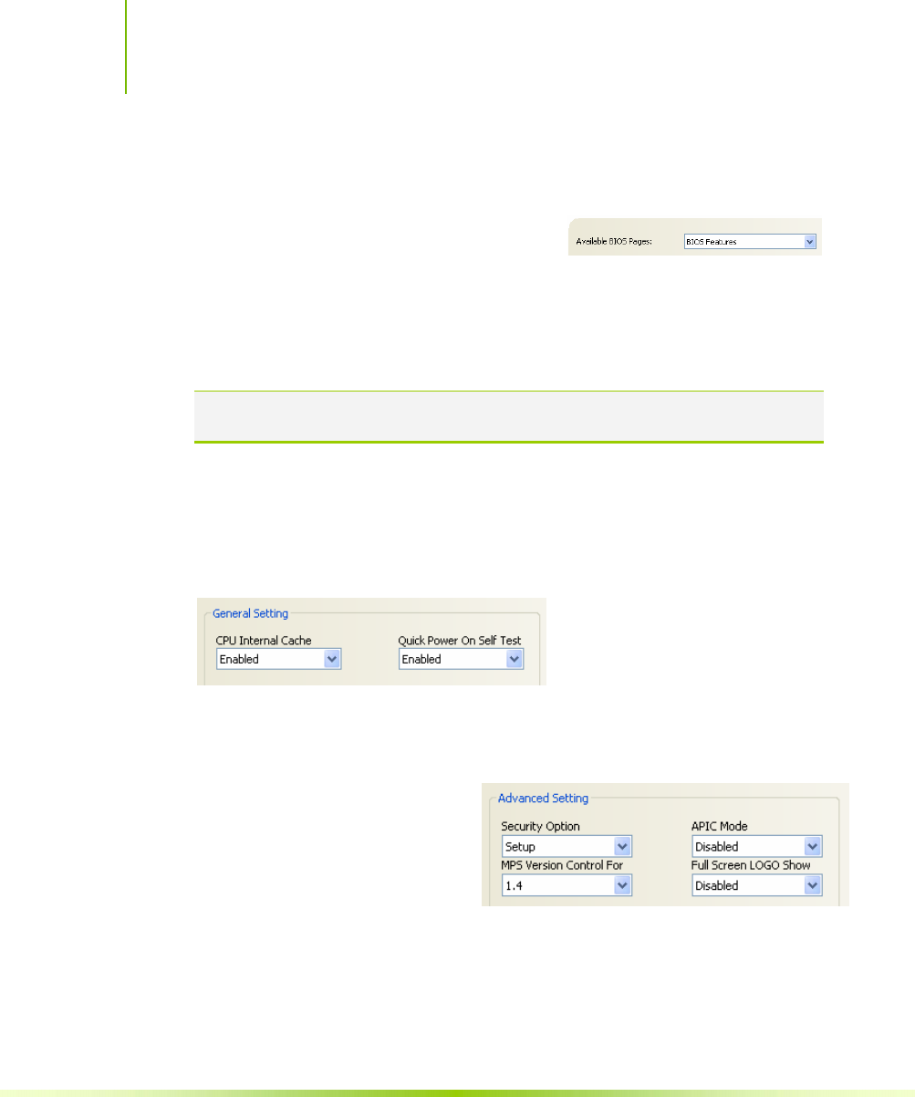
Installing and Configuring the NVIDIA nForce 650i Ultra Motherboard
84
Available BIOS Pages
In the Dynamic BIOS Access page, select a BIOS page that you
want to edit from the Available BIOS
Pages drop-down menu The BIOS page
you select determines which items on the Dynamic BIOS Access
menu are available for changing. To edit an item, select an option
from the drop-down menus associated with each item. When finished
making your changes, click OK or Apply.
Note: This feature is available only with BIOS support from the motherboard
manufacturer.
General Settings
This section of the Dynamic BIOS Access menu allows you to
Enable or Disable the CPU Internal Cache and the Quick Power on
Self Test (POST).
Advanced Settings
This section of the Dynamic BIOS Access menu allows you to set
the following options:
Security options
¾ Setup
¾ System
MPS Version Control For
¾ 1.1
¾ 1.4
APIC Mode
¾ Disabled
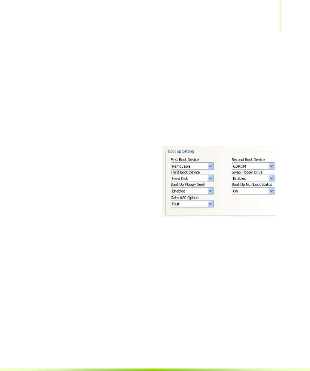
Using NVIDIA Software
85
¾ Enabled
Full Screen LOGO Show
¾ Disabled
¾ Enabled
Boot up Setting
This section of the Dynamic BIOS Access menu allows you to set
the following options:
First/Second/Third Boot Device
¾ Removable
¾ Hard Disk
¾ CDROM
¾ Legacy LAN
¾ Disable
Swap Floppy Drive
¾ Enable
¾ Disable
Boot Up Floppy Seek
¾ Enable
¾ Disable
Boot UP NumLock Status
¾ On
¾ Off
Gate A20 Option
¾ Normal
¾ Fast
Installing and Configuring the NVIDIA nForce 650i Ultra Motherboard
86
Automatic Tuning
The NVIDIA nTune performance manager uses a complex searching
algorithm to determine the best possible and most stable performance
for you system. The nTune tuning engine pushes your system to the
limits to test the highest possible performance settings. Because of
this, there may be instances of system hangs during the testing.
When you restart the system, nTune continues its tuning process
until the process is complete. It is highly recommended that you
check the Select to continue the tuning process upon reboot box at the
bottom of the Tune System screen. The effects of the tuning process
apply to the current Windows session only.
The nTune tuning engine runs internal benchmark tests on your
system and creates performance profiles and rules.
CAUTION: Make sure to save and close all work prior to running the Tune
System function. Close all applications and do not perform other tasks
during the tuning session.
Three tuning options are available on the Tune System menu:
Course tuning takes approximately 20 minutes to run while it
adjusts system bus speeds and parameters. It first saves current bus
speeds as two profiles: the Default.npe file with current bus speeds
and Bestsystem.npe with the highest passing settings.
Fine tuning takes approximately three (3) hours and performs a
more complex tuning on bus speeds, memory timings, and voltages.
This more complex testing achieves maximum performance.
Tuning using custom settings allows you to select specific areas to
test and the duration of the tests. Remember that a longer tuning
session results in more precise and stable settings. The progress of
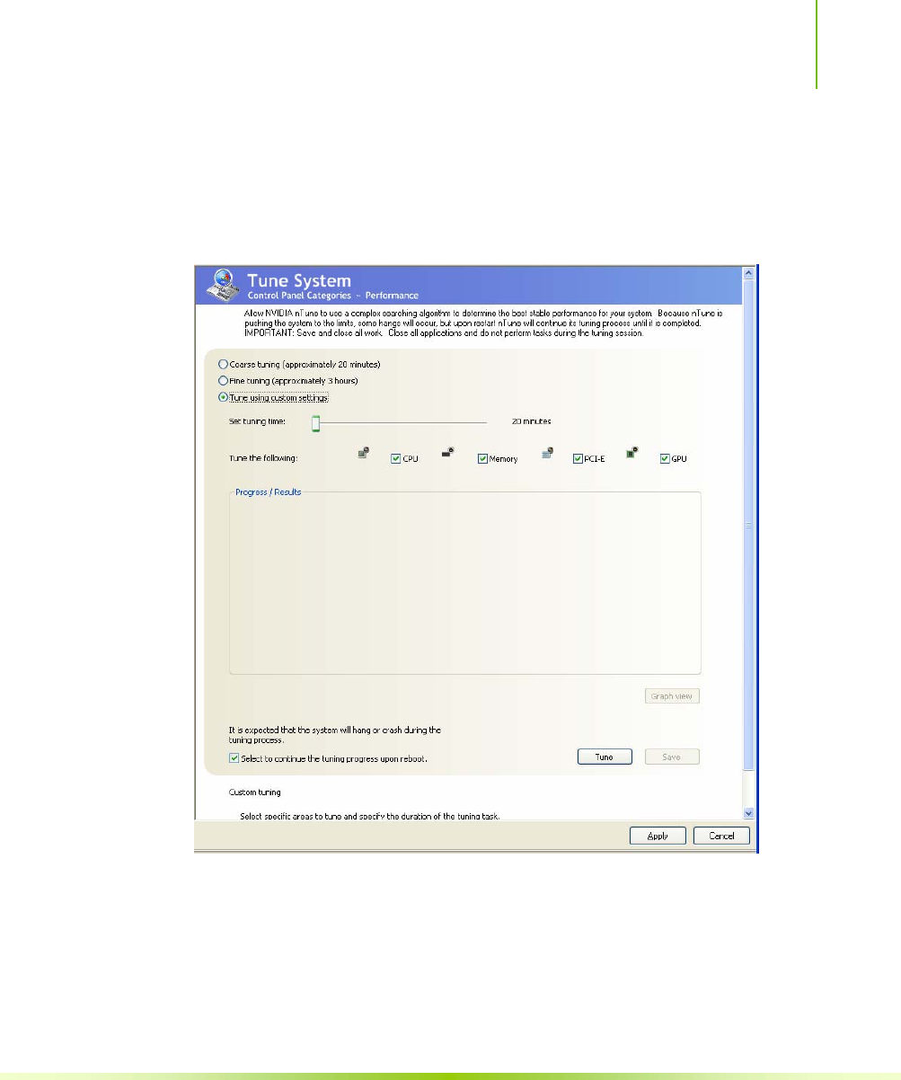
Using NVIDIA Software
87
your test and the results upon completion are displayed when the
benchmarks are being executed. You can cancel the tests at any
time.
Figure 22. Tune System Menu (nTune)
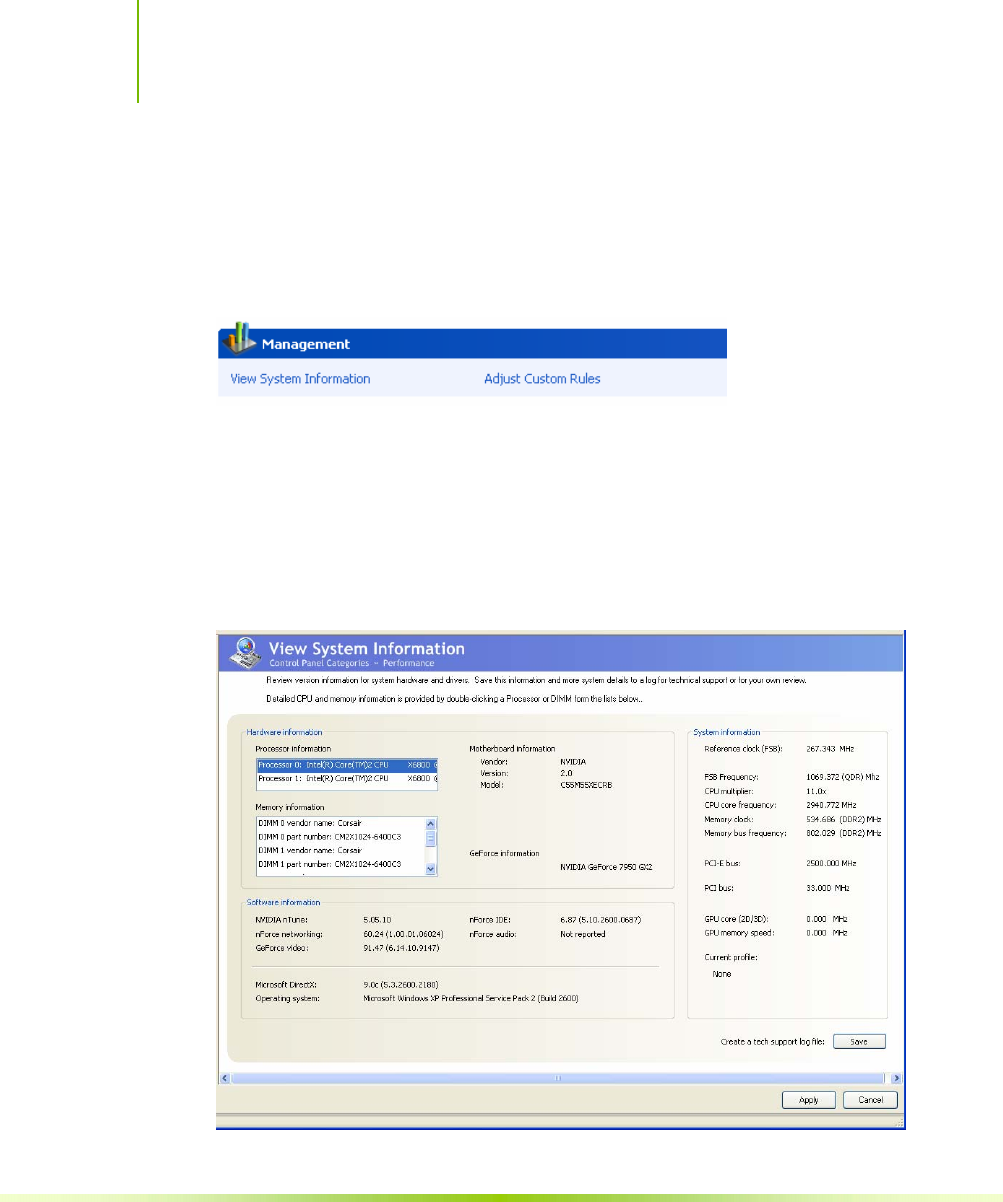
Installing and Configuring the NVIDIA nForce 650i Ultra Motherboard
88
Management
The Management option on the View System Information screen
allows you to view hardware, software, and system information and
adjust profiles.
View System Information
This screen is for information purposes only (you cannot make any
changes to the information). The View System Information screen
provides hardware, software, and system information that you can
save to a log file to assist customer support or for your own uses.
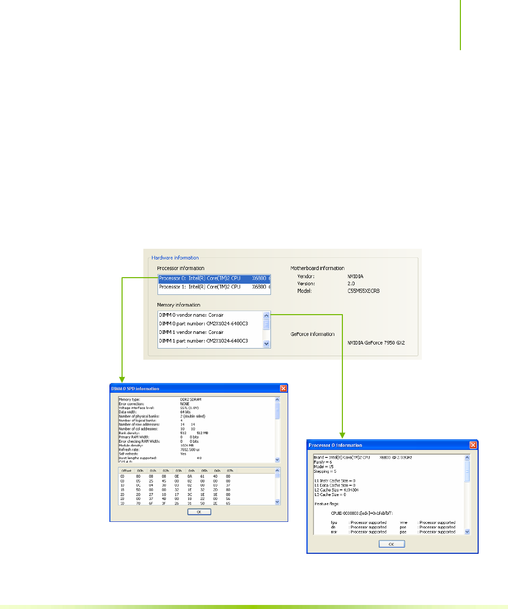
Using NVIDIA Software
89
Figure 23. View System Information (nTune)
Hardware and driver version information can be viewed and saved
using this interface. The status of the system, including current
system clock speeds, system temperatures, memory timings, and
system voltages can be logged. Versions of NVIDIA software and
other system software are listed under Software information.
Detailed CPU and memory information is displayed when you
double-click on a processor or DIMM listed under Hardware
information.
Double-click a DIMM
to display information
Double-click a processor to display information
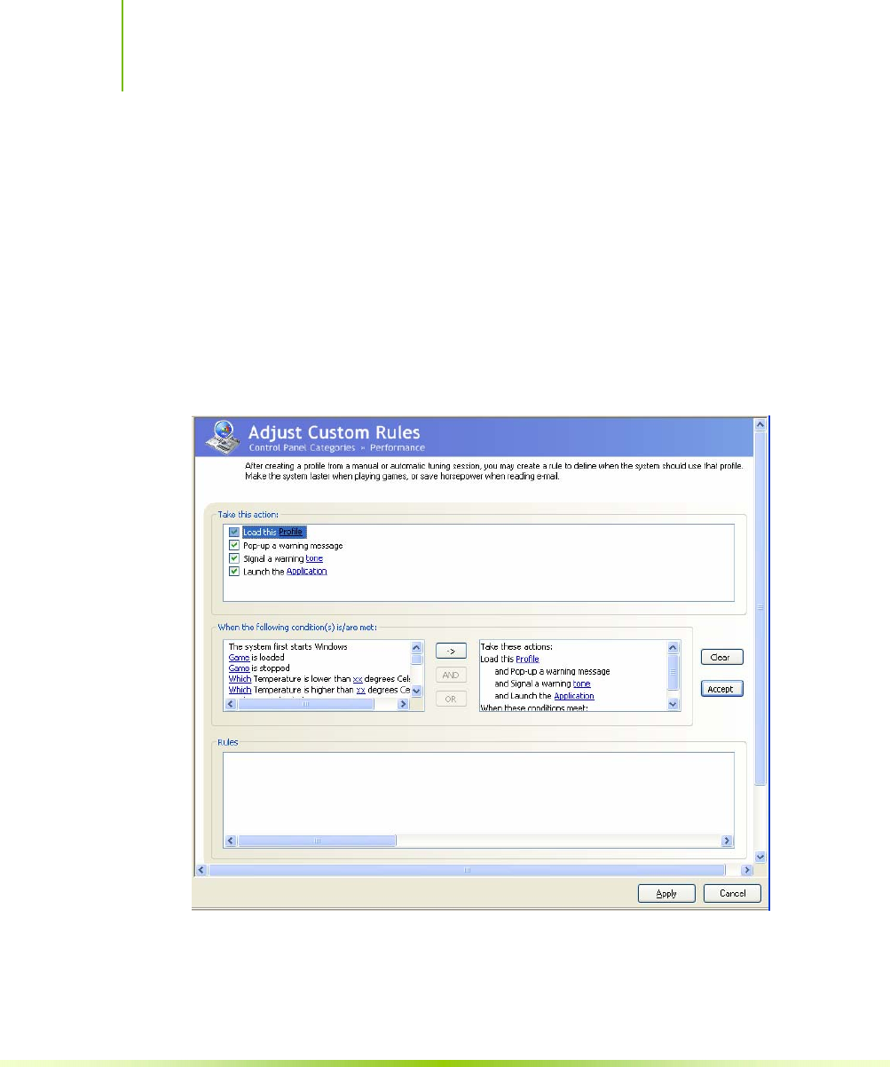
Installing and Configuring the NVIDIA nForce 650i Ultra Motherboard
90
Adjust Custom Rules
The Adjust Custom Rules selection provides you with the ability to
create a rule to define when the system should use a particular
profile (.nsu files or .npe files) that was created from a manual or
automatic tuning session.
With custom rules, you can make your system run faster when you
are playing games or make it run quieter when you are surfing the
Internet.
Figure 24. Adjust Custom Rules (nTune)
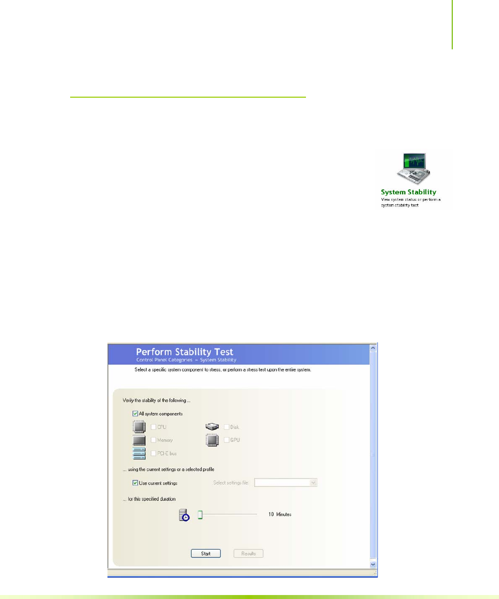
Using NVIDIA Software
91
System Stability
System Stability lets you view your system’s status and perform
system stability testing. To access the System
Stability menu, select Start¾All Programs¾NVIDIA
Corporation¾NVIDIA Control Panel and select System
Stability.
Perform Stability Test
Use Perform Stability Test to quickly diagnose potential system
performance issues and to gather troubleshooting data.
Stability Test performs a series of stress test to identify probable
causes of performance issues, creates a list of the results, and provides
recommendations for improvements. You can test the entire system
(check All system components) or check individual components.
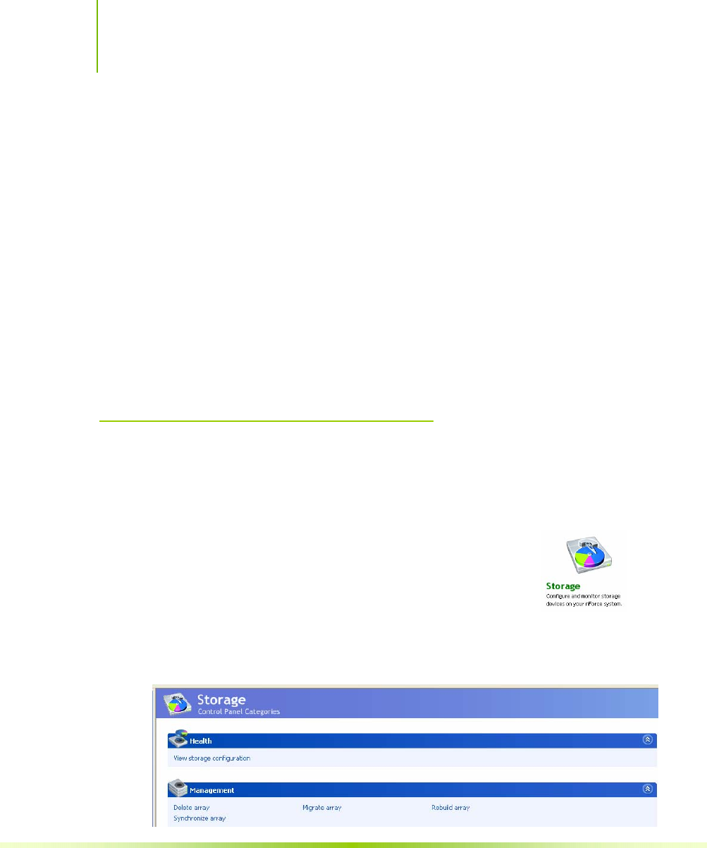
Installing and Configuring the NVIDIA nForce 650i Ultra Motherboard
92
Figure 25. Perform Stability Test
You can designate a specific settings profile to use or check Use
current settings for the tests. You can indicate the duration of the test
by changing the slider (slider values are from 10 minutes to 48
hours). Click Start to begin testing and display the NVPerformance
Benchmark display. Click Results to view a pop-up window
containing the testing results.
Note that when you click start to begin the testing, Clicking Stop
does not immediately stop the action in the NVPerformance
Benchmark window. The cycle completes before the test is actually
stopped.
Storage
The Storage application uses the NVIDIA MediaShield RAID
Manager technology to configure and control NVIDIA storage
hardware integrated into the NVIDIA MCP. NVIDIA
RAID technology can protect data from hardware
failure and provide increased file system performance.
To launch MediaShield, select Start¾All
Programs¾NVIDIA Corporation¾ NVIDIA Control Panel
and select Storage to displays the Storage Control Panel Categories
screen.
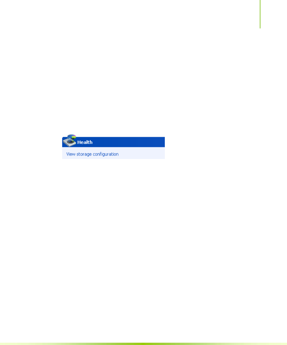
Using NVIDIA Software
93
Figure 26. Storage Control Panel Categories (MediaShield)
Health
The Health option on the Storage menu provides the ability for you
to view the current storage configuration.
View Storage Configuration
The View Storage Configuration screendisplays the current
configuration of your storage devices. Check this screen prior to
doing any management function. The View Storage Configuration
screen provides status and capacity for all the storage disks on your
system.
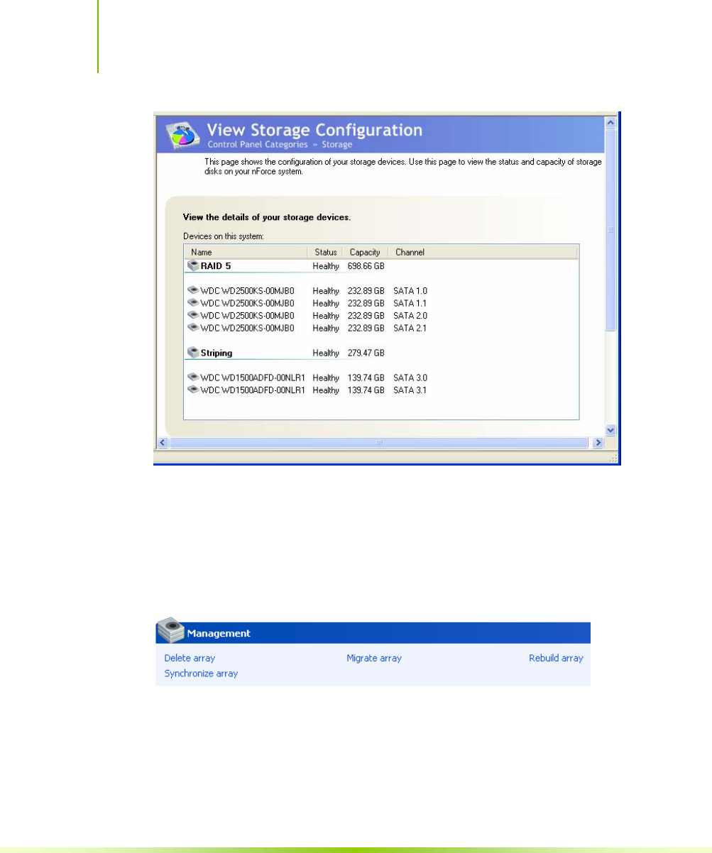
Installing and Configuring the NVIDIA nForce 650i Ultra Motherboard
94
Figure 27. View Storage Configuration (MediaShield)
Management
The Management options on the Storage menu provides you with
the ability to delete, rebuild, migrate, and synchronize arrays.
Delete Array
Use the following procedure to delete an array:
1. Click on Delete Array under Management to launch the NVIDIA
Delete Array Wizard.
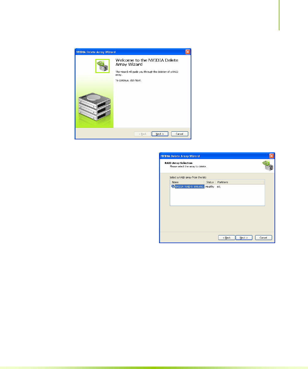
Using NVIDIA Software
95
2. Click Next to continue
with the wizard and
display the RAID Array
Selection menu.
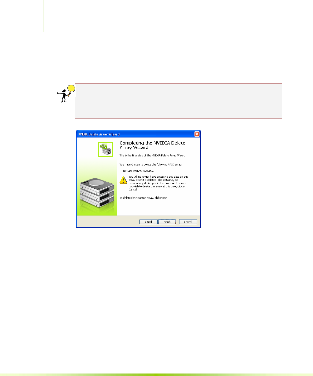
Installing and Configuring the NVIDIA nForce 650i Ultra Motherboard
96
3. Select an array you want to delete and press Next.
The Completing the NVIDIA Delete Array Wizard screen displays to verify
that you still want to delete the array selected.
CAUTION: Be sure you are deleting the correct array. Once you click
Finish, you no longer have access to any of the data on this array. The
data may be permanently destroyed in the process. If you do not want
to delete this array, click Cancel
4. Click Finish to delete the selected array.
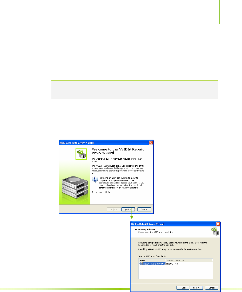
Using NVIDIA Software
97
Rebuild Array
The Rebuild Array option allows you to rebuild a disk in the array
while the system is running without disrupting user or application
access to the data set.
Note: Rebuilding an array can take up to a full day to complete. This operation
occurs in the background and does not impede any work being done. If you
need to shutdown, the rebuild operation continues upon restart.
Use the following procedure to rebuild an array:
1. Identify the affect disk in the array and replace it.
2. Click on Rebuild Array under Management to launch the NVIDIA
Rebuild Array Wizard.
3. Click Next to continue
with the wizard and display
the RAID Array Selection
menu.
4. Select the array with that
had the affected disk and
click Next.
Rebuilding a degrading
array adds a new disk to
that array. Data from the
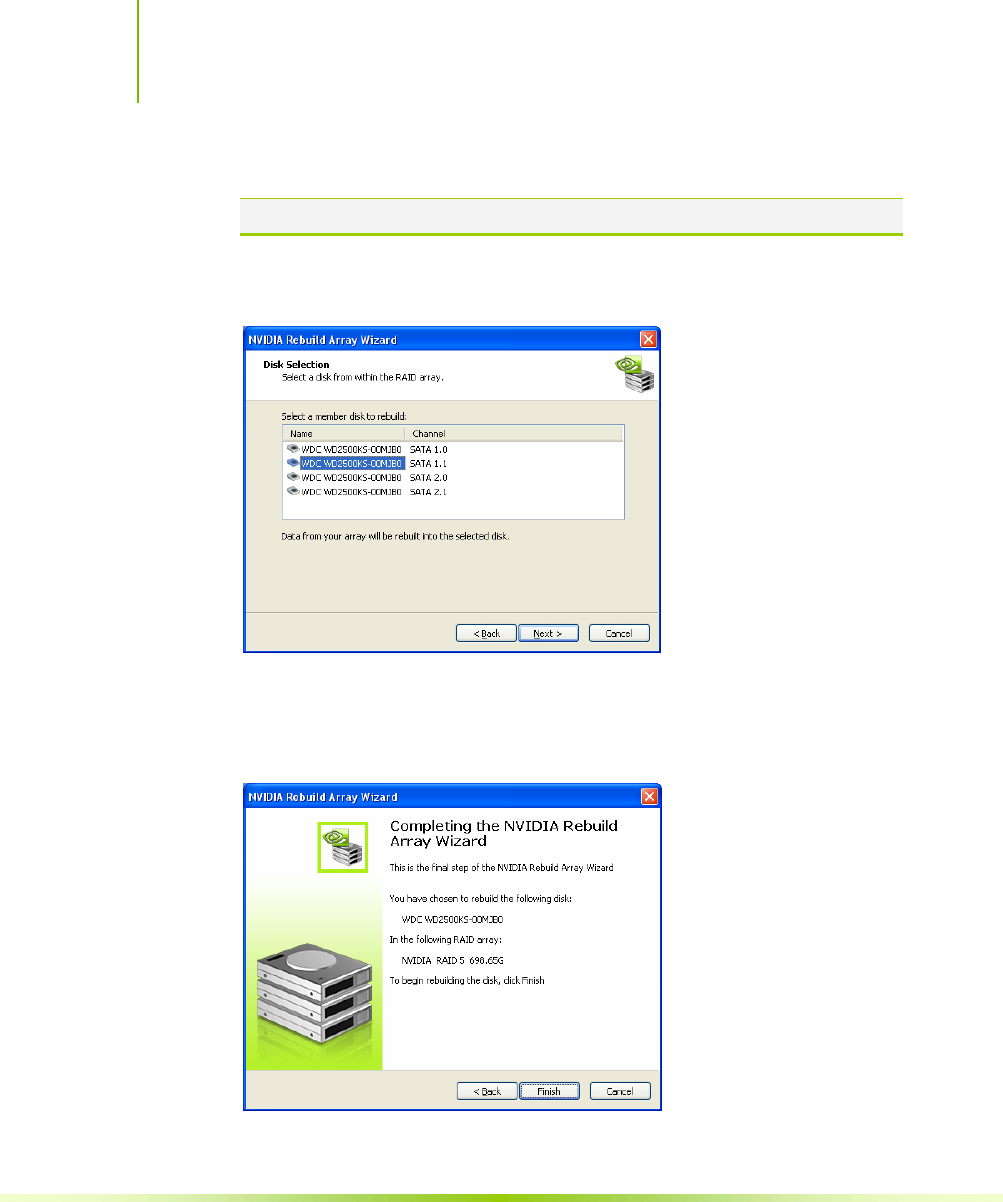
Installing and Configuring the NVIDIA nForce 650i Ultra Motherboard
98
healthy disk is rebuilt onto a new disk.
Note: Rebuilding a healthy RAID array resynchronizes the data set onto a disk.
5. Select the disk in the array that was replaced and needs to be
rebuilt.
6. Click Next.
The Completing the NVIDIA Rebuild Array Wizard screen displays to verify
that you still want to rebuild the array selected.

Using NVIDIA Software
99
7. Click Finish to begin the rebuild of the selected disk in the array.
(Remember that rebuilding a disk can take up to a full day.)
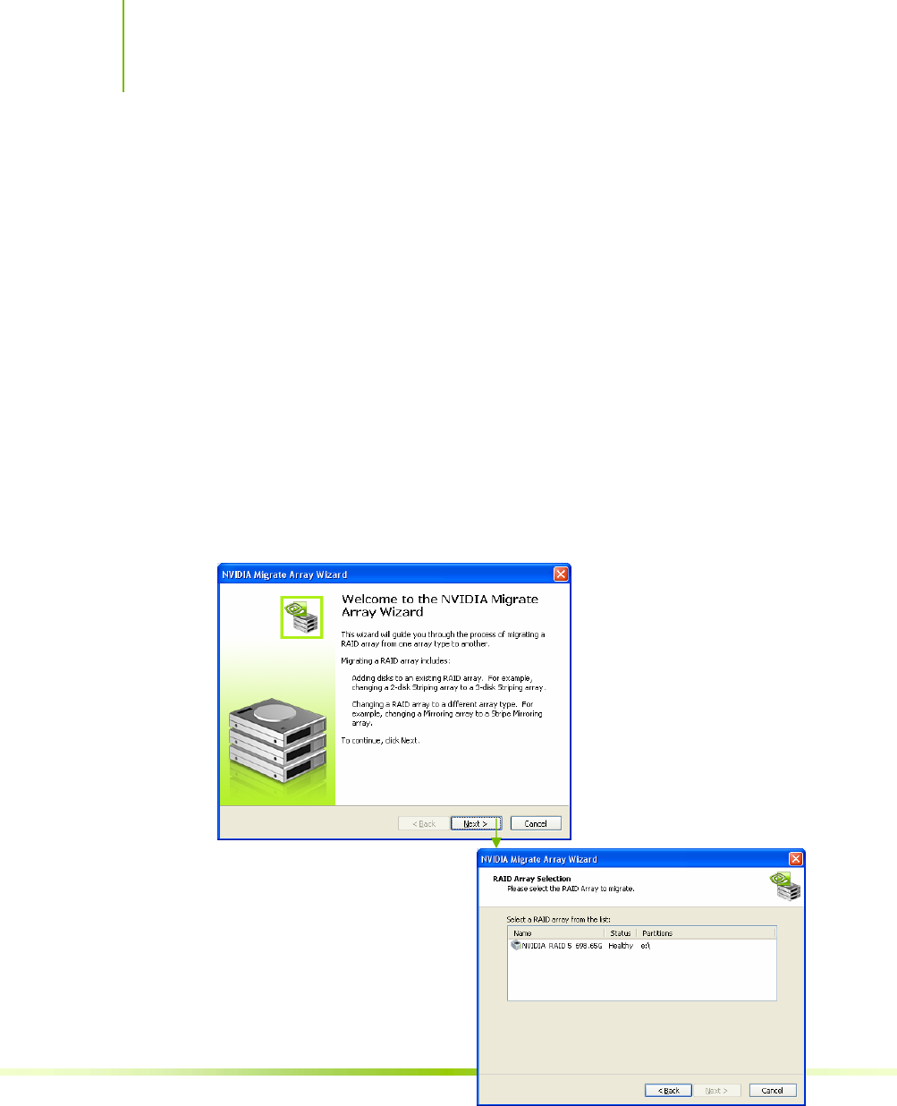
Installing and Configuring the NVIDIA nForce 650i Ultra Motherboard
100
Migrating Array
The Migrating Array option allows you to migrate a RAID array
from one arry type to another.
There are two reasons to use the Migrating Array option:
Adding disks to an existing RAID array
An example would be to change a 2-disk Striping array to a 3-disk
Striping array.
Changing a RAID array to a different array type
An example would be to change a Mirroring array to a Strip
Mirroring array.
Use the following procedure to rebuild an array:
1. Click on Migrate Array under Management to launch the NVIDIA
Migrate Array Wizard.
2. Click Next to continue
with the wizard and
display the RAID Array
Selection window.
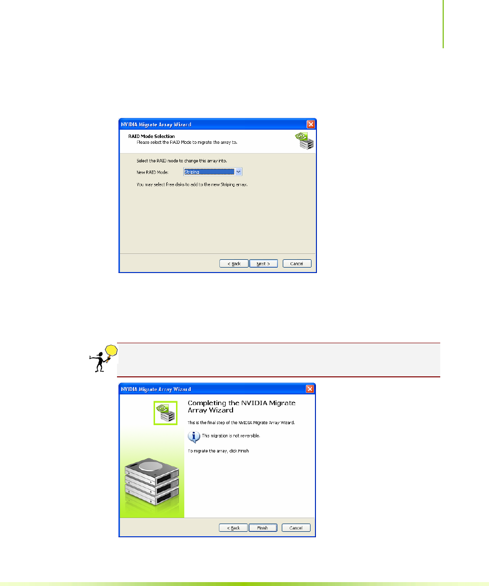
Using NVIDIA Software
101
3. Select the array to migrate and click Next to display the RAID
Mode Selection window.
4. Select the RAID mode you want to migrate to and click Next.
The Completing the NVIDIA Migrate Array Wizard screen displays to verify
that you still want to migrate the array selected.
CAUTION: Note that this migration is not reversible. Be sure you want
to migrate this array before continuing.
5. Click Finish to begin the migration of the selected array.
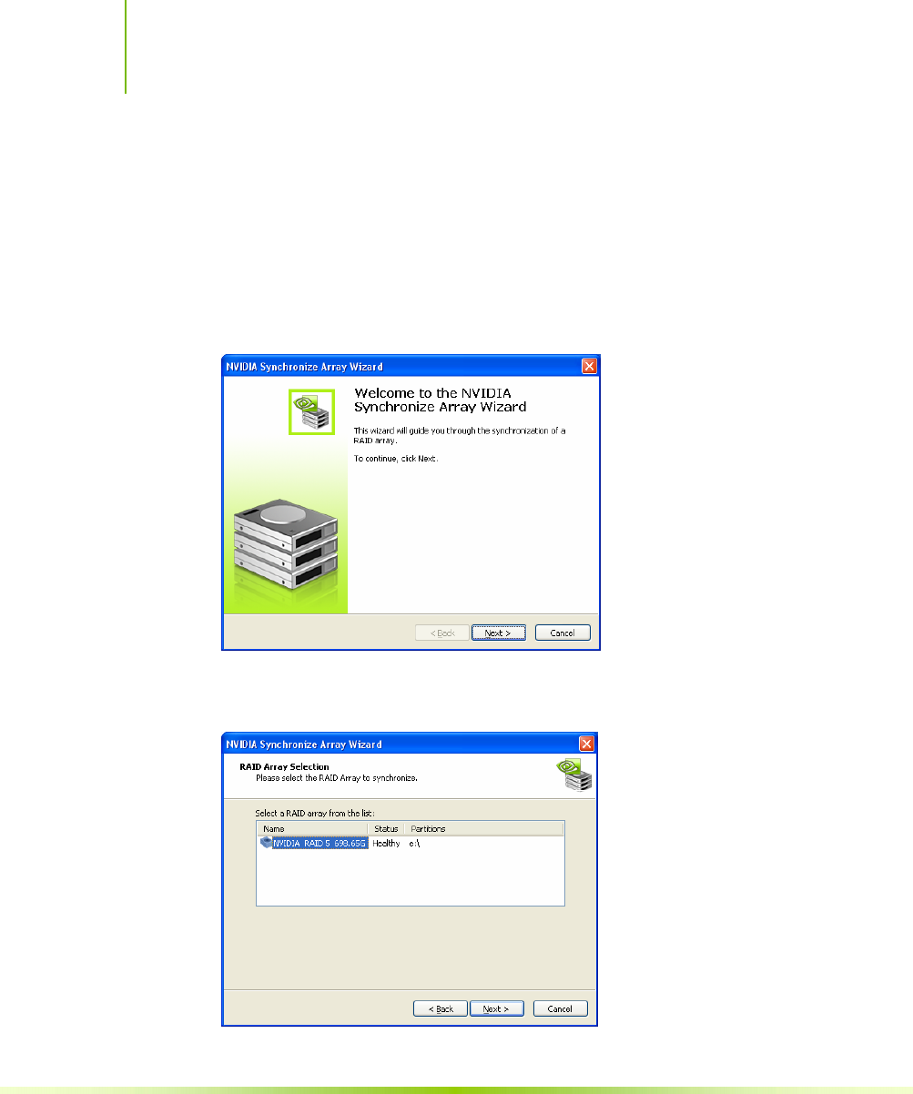
Installing and Configuring the NVIDIA nForce 650i Ultra Motherboard
102
Synchronize Array
This option is used to synchronize a selected array.
Use the following procedure to rebuild an array:
1. Click on Synchronize Array under Management to launch the
NVIDIA Synchronize Array Wizard.
2. Click Next to continue with the wizard and display the RAID
Array Selection window.
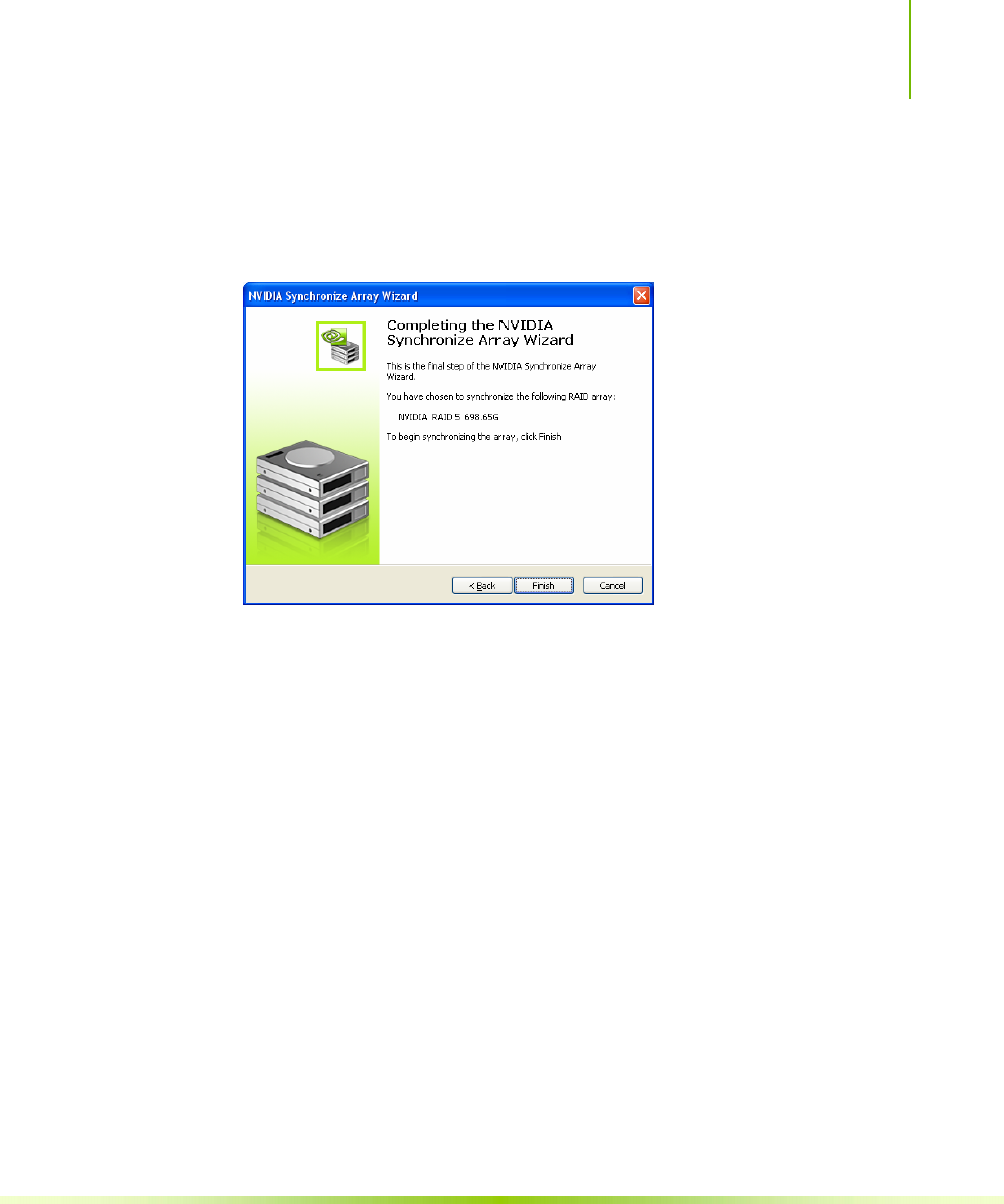
Using NVIDIA Software
103
3. Select the array to synchronize and click Next.
The Completing the NVIDIA Synchronize Array Wizard screen displays to
verify that you still want to synchronize the array selected.
4. Click Finish to begin synchronizing the array.

Installing and Configuring the NVIDIA nForce 650i Ultra Motherboard
104
NVIDIA Networking
The NVIDIA Networking function configures and controls NVIDIA
networking hardware integrated into the NVIDIA MCP. In addition
to the typical network configuration functions that are controlled
using the Windows Network Connections panel, the NVIDIA
networking solution includes several key features that are accessed
using the NVIDIA control panel.
FirstPacket
FirstPacket provides a better gaming experience over a broadband
connection when multiple applications on the same PC are
simultaneously transmitting data to the Internet
TCP/IP Acceleration
When TCP/IP acceleration is enabled, it lowers the CPU
utilization and provides overall better system performance when the
networking traffic is mainly TCP/IP.
To launch the NVIDIA Control Panel, select Start¾All Programs
¾NVIDIA Corporation¾NVIDIA Control Panel. Click on the Networking
icon.
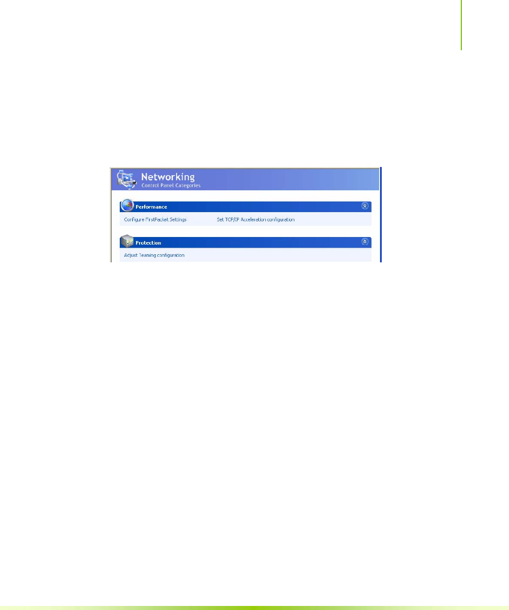
Using NVIDIA Software
105
Performance
The Performance option on the Networking Control Panel
Categories screen provides the means to configure FirstPacket settings
and to set TCP/IP acceleration configuration.
Figure 28. Networking Control Panel Categories
First Packet
NVIDIA FirstPacket offers a new way to manage the traffic on your
personal computer, allowing you to more effectively manage and
improve the performance of networked games and other applications
that are sensitive to network delay (latency), such as Voice-over-IP
(VoIP).
FirstPacket creates an additional transmit queue in the network
driver so that network applications can share a limited resource.
Based on user preference, FirstPacket can expedite transmission for
user-approved network applications.
For example, when FirstPacket is enabled:
A game that was previously unplayable can be completely usable
VoIP connections will not be dropped due to the network traffic
on a local computer.
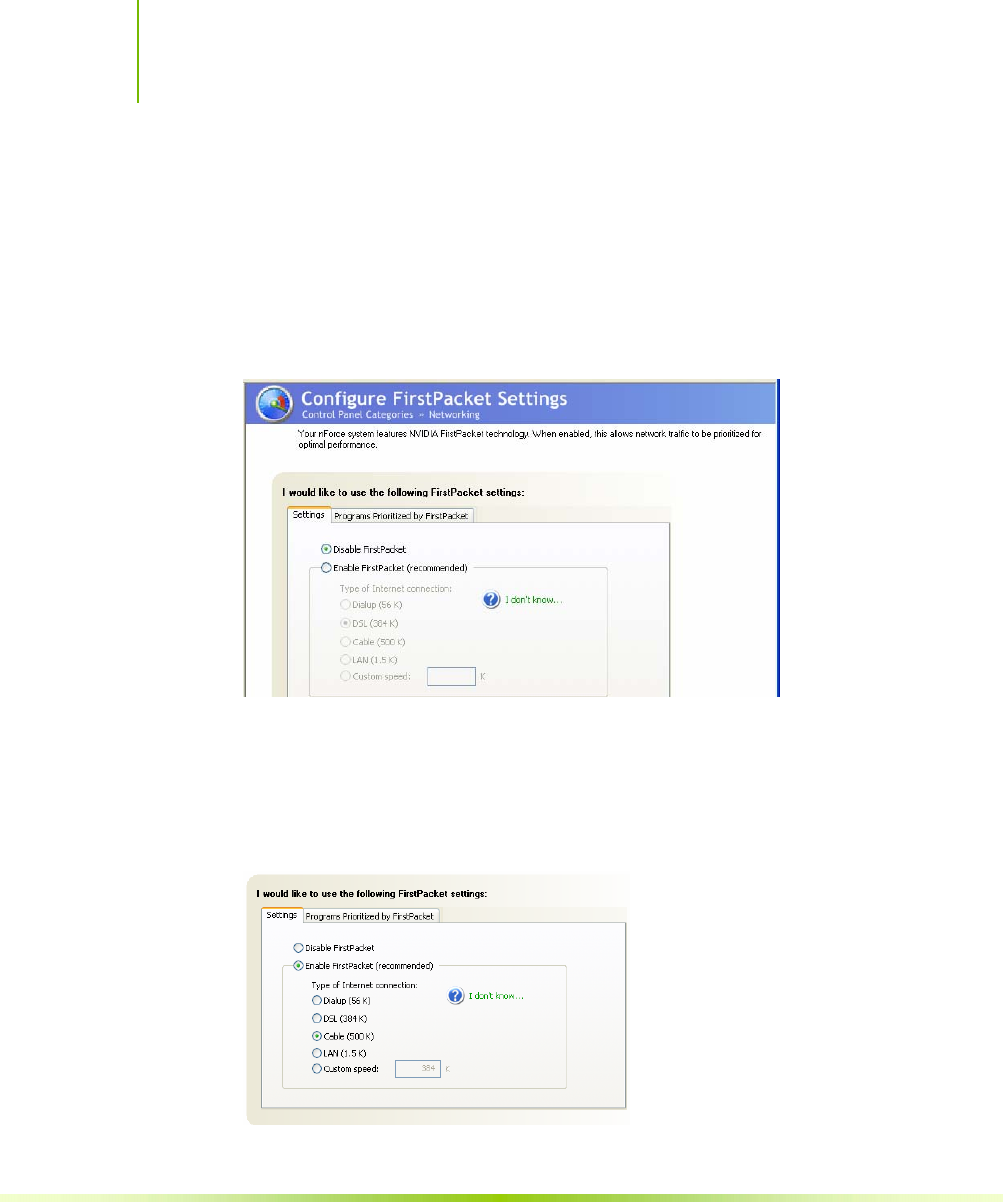
Installing and Configuring the NVIDIA nForce 650i Ultra Motherboard
106
Use the following procedure to enable or disable the ability to have
network traffic to prioritized for optimal performance:
1. Select Configure FirstPacket Settings under Performance on the
Networking Control Panel Categories screen to display the
Configure FirstPacket Settings screen.
2. Click the Settings tab.
3. Click Enable FirstPacket (recommended) to enable the options that
define the speed of the broadband connection. This information is
needed by the FirstPacket software to appropriately prioritize
network traffic.
Select the appropriate speed for
your network. For example, if
your broadband connection is a
cable connection, click the Cable
button.
Custom bandwidth connections
can be directly configured in the
provided text box.
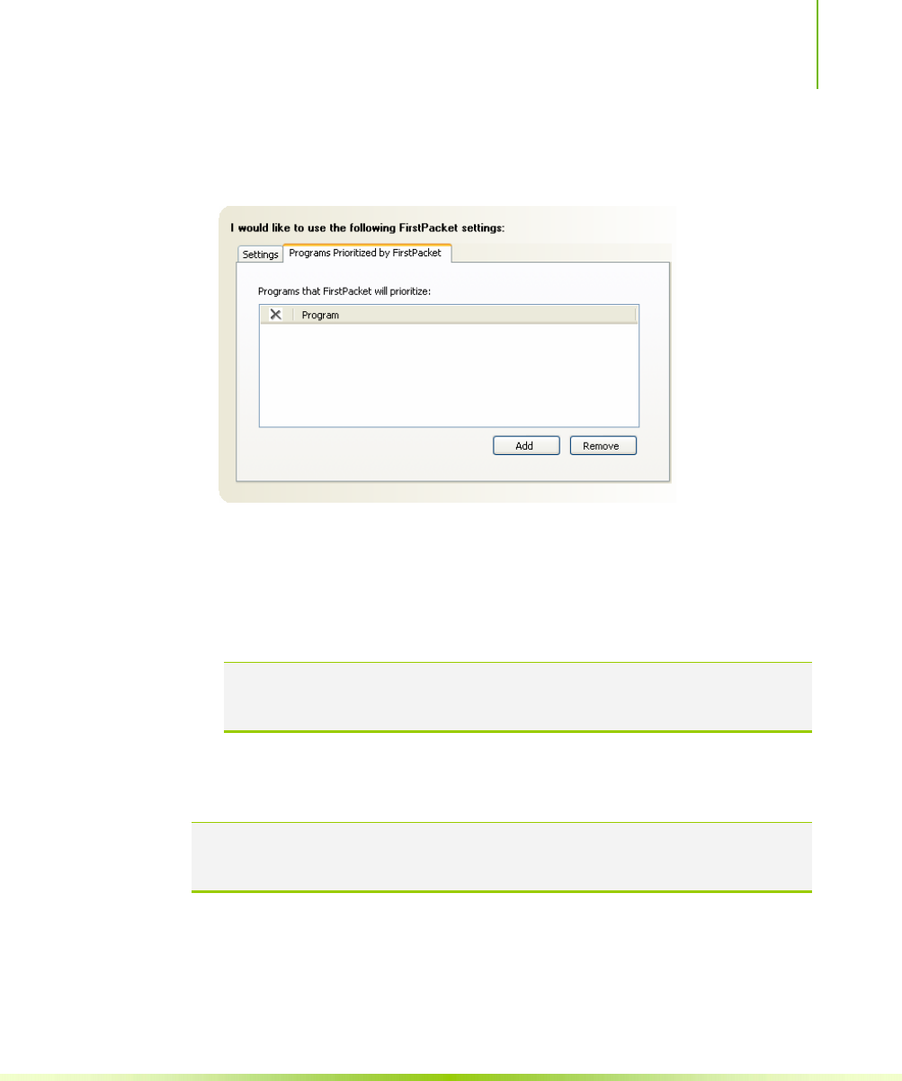
Using NVIDIA Software
107
4. Define the applications to accelerate by clicking Program Prioritized
by FirstPacket.
5. Click Add to browse for an executable gamming applications. For
example, if you want to accelerate a game such as Serious Sam 2,
look for the Sam2.exe and add it.
6. Click Apply.
Note: Only applications that are added to the Programs Prioritized by
FirstPacket section are prioritized and benefit from FirstPacket
technology
TCP/IP Acceleration
Note: Enabling TCP/IP acceleration enhances your network performance but can
cause your network traffic to bypass the firewall because all processes are
off-loaded to the hardware.
NVIDIA TCP/IP Acceleration technology is a networking solution
that moves the processing of TCP/IP network traffic from your
computer’s CPU to its nForce hardware resulting in greatly
improved system performance.
NVIDIA TCP/IP Acceleration provides deep levels of networking

Installing and Configuring the NVIDIA nForce 650i Ultra Motherboard
108
and traffic inspections at full-duplex gigabit Ethernet speeds. Overall
system performance is greatly improved because the CPU is not tied
up processing network traffic, especially at gigabit Ethernet speed.
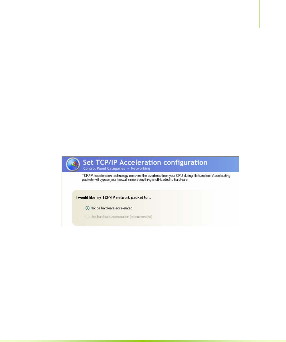
Using NVIDIA Software
109
In traditional networking environments, inspecting packets is
laborious and affects CPU overhead, memory bandwidth, and overall
system latency. In comparison, the NVIDIA TCP/IP Acceleration
engine discards bad packets before the CPU detects them. In addition,
good packets take an “express lane” and bypass the traditional
“network stack” process, improving overall throughput and lowering
CPU utilization.
T configure TCP/IP acceleration, select Set TCP/IP Acceleration
configuration from the Networking screen. Note that by default,
TCP/IP acceleration is turned off (the Not be hardware-accelerated
radio button is checked). Click the Use hardware-acceleration
(recommended) radio button to enable TCP/IP acceleration. Click
Apply to save changes.
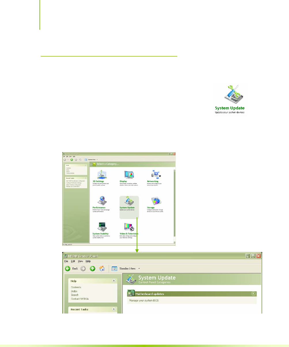
Installing and Configuring the NVIDIA nForce 650i Ultra Motherboard
110
System Update
The System Update application is accessible from
the NVIDIA Control Panel and is used to manage
the system BIOS without having to go into the
BIOS.
To launch the NVIDIA Control Panel, select
Start¾All Programs ¾NVIDIA Corporation¾NVIDIA Control Panel. Click
on the System Update icon.
Figure 29. System Update Application on the NVIDIA
Control Panel

Using NVIDIA Software
111
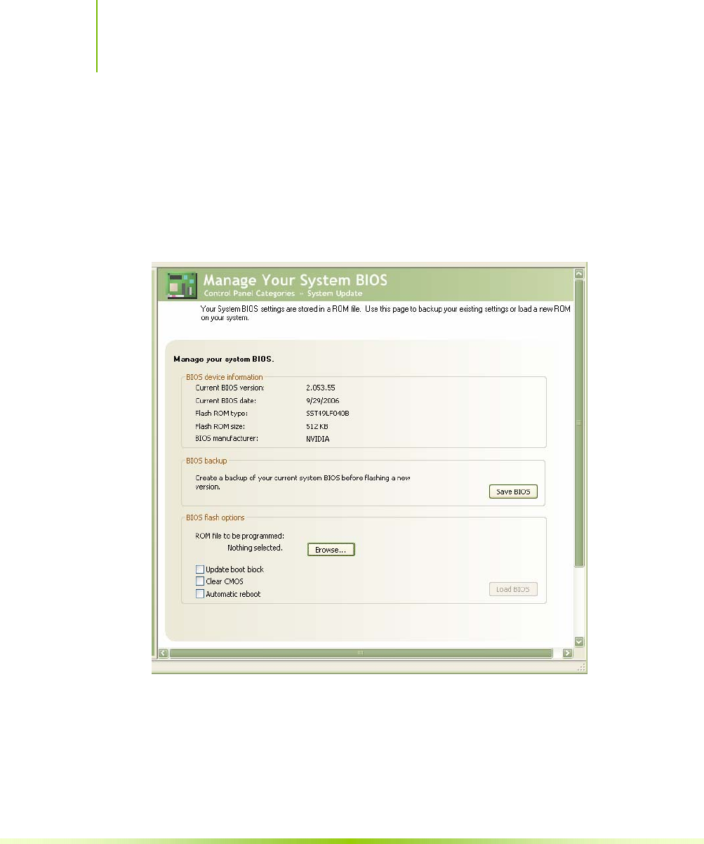
Installing and Configuring the NVIDIA nForce 650i Ultra Motherboard
112
Motherboard Updates
Currently, there is one selection under Motherboard updates.
Selecting Manage your system BIOS displays a screen that allows you
to backup the existing settings stored in the ROM file or load a new
ROM file onto your system.
Figure 30. Managing Your System Bios Screen
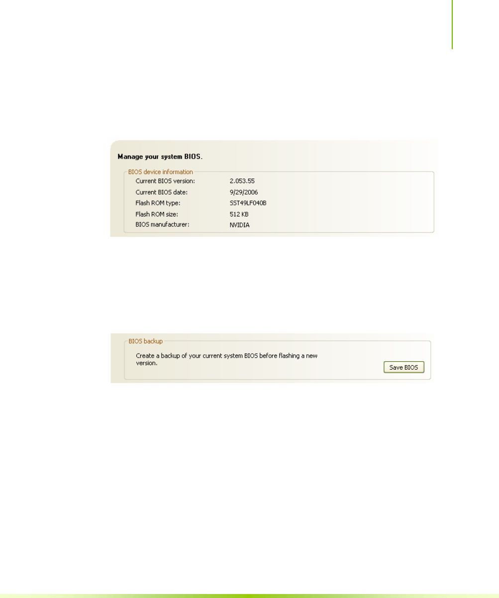
Using NVIDIA Software
113
Manage Your System BIOS
This section of the screen shows your current BIOS device
information. This is a read-only section.
BIOS Backup
This section of the screen allows you to create a backup of the
current BIOS before flashing a new version. Click on the Save BIOS
button and save the BIOS version to a location on your drive.
BIOS Flash Options
This section of the screen has three options:
Update boot block
Select this option to overwrite the BIOS boot block during flash.
It is not recommended to use this option unless specified by the
provider of the BIOS Update.
Clear CMOS
Select this option to clear the CMOS on the next reboot. Use this
option when BIOS updates require that the CMOS be cleared after
the update is performed.

Installing and Configuring the NVIDIA nForce 650i Ultra Motherboard
114
Automatic reboot
Select this option to automatically reboot after the flash update is
completed. Index
2-Port SATA Power Cable.................8
ACPI function ............................... 56
ACPI Suspend Type....................... 57
Adjust Custom Rules.....................84
adjust motherboard settings ..........69
Advanced BIOS Features ............... 34
Advanced Chipset Functions menu . 39
Advanced Programmable Interrupt
Controller ................................. 38
APIC............................................ 38
Async Latency .............................. 75
ATX form factor..............................5
auto-detect IDE and SATA channels31
Automatic Tuning, nTune .............. 80
Base Memory............................. 33
BIOS CMOS Setup Utility Main Menu27
BIOS menus
Advanced BIOS Features menu...34
Advanced Chipset Features ........39
CMOS Setup Utility menu........... 27
CPU Configuration.....................47
FSB & Memory Config ................43
Integrated Peripherals................52
Main Menu................................26
Memory Timing Setting ..............45
PnP/PCI Configuration................59
Power Management Setup..........56
Standard CMOS Features............29
System Clocks...........................40
System Monitor menu................62
System Voltages........................48
BIOS, configuring..........................25
block mode, IDE HDD....................55
boot device priority........................37
Boot-up settings............................79
C1E Enhanced Halt State...........48
CAS Latency .................................74
Chassis Backpanel Connectors........10
CHS.............................................31
Clock Drive Strength......................75
CMOS RAM jumper........................24

Installing Graphics Cards in an SLI Configuration
115
Comm2 Bracket Cable.....................8
Command Per Clock.............46, 75
configure IDE and SATA channels,
BIOS........................................ 30
configuring the BIOS..................... 25
connectors
COM1.......................................22
CPU fan.................................... 22
FDD ......................................... 22
IDE.......................................... 17
PWR1.......................................16
PWR2.......................................17
SATA........................................ 18
Cooling fan for CPU........................ xi
CPU Configuration menu................ 47
CPU cooling fan ............................. xi
CPU Core 1................................. 48
CPU fan ..................................13, 22
CPU Freq.................................... 41
CPU internal cache........................ 36
CPU Multiplier............................ 41
CPU Spread Spectrum...............42
CPU Thermal Control................. 47
CPU, installing ..............................12
date and time, setting in BIOS .......30
DDR2 memory.............................. 13
drivers, shipped in kit.................... 64
dual channel DDR2 ....................... 13
Dynamic BIOS Access ...............77
Dynamic Fan Control menu............63
equipment list.................................7
ESCD............................................60
Execute Disable Bit....................48
expansion slots .............................23
Extended Memory......................33
FDC controller function..................55
features, motherboard.....................1
FirstPacket.........................96, 97, 98
FirstPacket technology.....................3
Floppy Cable...................................7
Frequency Settings........................41
front panel header.........................19
Front Panel Header Pins.................20
front panel power LED...................19
FSB & Memory Config menu...........43
FSB (QDR)..................................44
FSB and Memory Clock Mode....44
FSB Reference Clock..................41
FSB speeds.....................................1
full-screen logo .............................38
Gigabit Ethernet..............................3
GPU, adjust settings......................75
Halt On sub-menu........................32
hard disk audio function.................55
Hard Disk Boot Priority...................36
hard disk drive indicator LED..........19
HD_LED......................................19

Installing and Configuring the NVIDIA nForce 650i Ultra Motherboard
116
Health option................................ 87
high definition audio........................4
High Precision Even Timer.............51
hot key power on..........................59
How to
configure CPU in BIOS...............47
configure FirstPacket ................. 98
configure nTune........................68
configure RAID in BIOS.............. 54
configure USB in BIOS............... 54
connect IDE drives .................... 17
connect power to motherboard... 16
delete an array.......................... 88
install CPU................................ 12
install DIMMs............................ 13
migrate an array .......................92
monitor system performance,
voltages, temperatures........... 67
set CMOS jumper ......................24
set date and time...................... 30
set disk priority ......................... 36
set fan speeds in BIOS...............62
set fan speeds with BIOS........... 63
set IDE functions in BIOS........... 53
set network boot priority............ 36
set power management functions in
BIOS.....................................56
set system voltages in BIOS....... 48
set TCP/IP Acceleration
configuration .......................101
synchronize an array..................94
HPET............................................51
HT Multiplier.................................42
HT Spread Spectrum..................42
I/O shield .....................................14
I/O Shield.......................................7
IDE connector...............................17
IDE DMA transfer access...........53
IDE Function Setup menu ..............53
IDE Prefetch Mode ........................53
IDE/SATA sub-menu......................30
IDE-ATA 133 HDD Cable..................8
installing
CPU..........................................12
I/O shield..................................14
memory DIMMs.........................13
motherboard.............................14
installing software.........................64
Integrated Peripherals menu..........52
Intel microprocessor.......................xi
internal headers............................19
PWRHD_LED.............................19
PWRLED ...................................19
PWRSW....................................19
IRQ Resources..............................61
LBA.............................................31
Legacy ISA ...................................61

Installing Graphics Cards in an SLI Configuration
117
Limit CPUID MaxVal.................. 47
load plate.....................................12
MAC Config menu ......................... 55
Manual Tuning.............................. 69
MediaShield....................................2
MediaShield RAID Manager............86
MEM (DDR)................................ 44
Memory bank switch .....................74
memory support............................ xi
Memory Timing............................. 73
Memory Timing Setting............. 45
microprocessor.............................. xi
motherboard
install procedure........................14
motherboard specifications..............5
MPS.............................................38
Multi-Processor Specification.......... 38
Network Boot Priority.................... 36
nTune.......................................... 68
NumLock status..........................37
NVIDIA Control Panel.................... 66
System Update........................ 102
NVIDIA EX support........................51
NVIDIA memory testing module..... 50
NVIDIA Monitor application............ 67
NVIDIA Networking function.......... 96
NVIDIA nForce 680i SE Motherboard 7
NVIDIA nForce 680i SE Motherboard
Layout........................................9
NVPerformance Benchmark............86
onboard serial port 1 function.........55
OnChip IDE Channel0................53
OnChip USB................................54
overclocking tools............................1
Palette Snoop function...................61
paring the motherboard.................12
PCI Express x1 slot........................24
PCI Express x16 slots.....................24
PCI slots.......................................23
PCIe Spread Spectrum ..............42
PCIe x16 ....................................41
Performance category....................68
Performance Control Panel Categories
................................................68
Performance option.......................97
PnP/PCI Configuration menu..........59
power button cable .......................19
Power Management Setup menu ....56
Power-on by alarm function ...........57
power-on function.........................57
Primary Master/Slave PIO ........53
Primary Master/Slave UDMA ....53
PWR1 connector............................16
PWR1 pin assignments...................16
PWR2 connector............................17
PWRLED.....................................19
PWRSW......................................19
Quick Power On Self Test...............37

Installing and Configuring the NVIDIA nForce 650i Ultra Motherboard
118
R to W Turnaround ....................... 74
RAID Array
delete....................................... 88
migrate .................................... 92
rebuild...................................... 90
synchronize .............................. 94
RAID Config menu ........................ 54
RAS to CAS access........................ 73
RAS to RAS Delay .........................74
Read-to-Read time........................ 74
rebuild an array............................ 90
Ref Clock, SPP MCP .................41
Refresh Rate ................................ 74
removable device startup priority ... 36
RESET.........................................19
Reset switch cable ........................19
Row Address Strobe...................... 73
Row Cycle Time............................ 74
safety instructions......................... 11
SATA Signal Cable...........................8
SATA Spread Spectrum ............. 42
Security Options ........................... 38
Serial ATA II connector..................18
Serial-ATA Controller ................ 53
How to......................................... 40
Soft-Off by PBNT ..........................57
software installation instructions.....64
Spread Spectrum.......................... 42
Standard CMOS Features menu......29
Storage application........................86
System Clocks...............................70
System Clocks menu......................40
system fan....................................22
System Monitor menu....................62
System Stability menu ...................85
System Updater ..........................102
System Voltages............................71
system voltages and timing settings51
System Voltages menu ..................48
tCL ....................................... 46, 74
TCP/IP acceleration.......................96
TCP/IP Acceleration technology......99
tCPC.............................................75
TLP payload size ...........................61
Total Memory.............................33
tRAS ..................................... 46, 73
tRC .............................................46
tRDC ...........................................46
tRDRD..........................................74
tREF ...........................................46
tRP .............................................46
tRRD ...........................................46
Tune System Menu........................81
tWR .............................................46
tWRD...........................................74
tWRWR ........................................74

Installing Graphics Cards in an SLI Configuration
119
tWTR ...........................................46
unpacking the kit............................7
USB 2.0 4-Port Cable.......................8
USB 2.0 ports............................... 21
USB Config menu.......................... 54
USB Keyboard/Mouse Support. 55
View Storage Configuration screen..87
View System Information screen.....82
Virtualization Technology .........48
W to R Termination Turnaround .....73
Write Recovery Time .....................73
Write-to-Write timing.....................74

Installing and Configuring the NVIDIA nForce 650i Ultra Motherboard
120

121
主机板规格简介
处理器
¾ 支持 Intel® Core™ 2 Extreme (酷睿™ 2 至尊处理器), Intel® Core™
2 Quad(英特尔®酷睿™ 2 四核), Intel® Core™ 2 Duo(英特尔®酷睿
™ 2 双核), Pentium®系列, 支持 Intel Socket 775 架构处理器
¾ 支持 FSB 1333(Core 2 Duo 1333)/1066/800/533 MHz系统总线
¾ 支持 HyperTransport(HT) 总线技术
¾ 支持 Windows XP 32bit/64bit, Windows Vista 32bit/64bit操作系统
芯片组
¾ 采用 NVIDIA nForce 650i Ultra 芯片组设计
内存
¾ 提供 4条240-pin 1.8V DDRII模块扩展内存插槽
¾ 支持双通道 DDR2 533/667/800内存模块,最大可扩展至 8.0GB
外围扩展设备特性
¾ 1个IDE 通道,可连接 2个IDE 设备,支持 ATA33/66/100/133
¾ 1个FDD 软驱接口,可支持格式为 360K/720K/1.2M/1.44M/2.88M
¾ 4个串行 SATA2 高速硬盘接口,传输速率为 3Gb/s,支持 RAID 0,
RAID 1, RAID 0+1, RAID 5, 和JBOD 模式,支持热插拔和 NCQ 技术,
支持 NVIDIA MediaShield™ RAID(确保数据安全)
¾ 8个USB 接口(前置 4个,后置 4个),支持 USB2.0 设备,兼容
USB 1.1
¾ 2个PS/2 端口(一个键盘和一个鼠标)
¾ 1个RJ-45 千兆网接口
¾ 1个SPDIF 输出接口
¾ 1个9针串行端口连接头

Installing and Configuring the NVIDIA nForce 650i Ultra Motherboard
122
内建 8声道音频设备
¾ 整合 Azalia 8 声道高清晰数字音频控制器
¾ 支持 8声道 3D 环绕定位音响效果
¾ 支持多路立体声混频
¾ 提供前置音频及扩展音频接口,支持插孔感应功能
¾ 支持 S/PDIF 输出
网卡
¾ 整合千兆网络控制芯片
¾ 支持 10/100/1000M 数据传输率
扩展插槽
¾ 1个PCI Expresss x16 插槽
¾ 2个PCI Expresss x1 插槽
¾ 3个PCI 插槽,兼容 PCI2.2
绿色功能
¾ 支持高级电源管理 ACPI 功能,支持 S0, S1, S3, S4, S5 模式
主板结构
¾ 采用 ATX 板型, 30.5CM x 24.4CM

NVIDIA Corporation
2701 San Tomas Expressway
Santa Clara, CA 95050
www.nvidia.com
Notice
ALL NVIDIA DESIGN SPECIFICATIONS, REFERENCE BOARDS, FILES, DRAWINGS,
DIAGNOSTICS, LISTS, AND OTHER DOCUMENTS (TOGETHER AND SEPARATELY, “MATERIALS”)
ARE BEING PROVIDED “AS IS.” NVIDIA MAKES NO WARRANTIES, EXPRESSED, IMPLIED,
STATUTORY, OR OTHERWISE WITH RESPECT TO THE MATERIALS, AND EXPRESSLY
DISCLAIMS ALL IMPLIED WARRANTIES OF NONINFRINGEMENT, MERCHANTABILITY, AND
FITNESS FOR A PARTICULAR PURPOSE.
Information furnished is believed to be accurate and reliable. However, NVIDIA Corporation
assumes no responsibility for the consequences of use of such information or for any
infringement of patents or other rights of third parties that may result from its use. No license
is granted by implication or otherwise under any patent or patent rights of NVIDIA Corporation.
Specifications mentioned in this publication are subject to change without notice. This
publication supersedes and replaces all information previously supplied. NVIDIA Corporation
products are not authorized for use as critical components in life support devices or systems
without express written approval of NVIDIA Corporation.
Trademarks
NVIDIA, the NVIDIA logo, NVIDIA nForce, GeForce, NVIDIA Forceware, NVIDIA SLI, NVIDIA
FirstPacket, NVIDIA DualNet, NVIDIA nTune, Linkboost, and MediaShield are trademarks or
registered trademarks of NVIDIA Corporation. Other company and product names may be
trademarks of the respective companies with which they are associated.
Copyright
© 2007 NVIDIA Corporation. All rights reserved.
