OBO PRO 2 DWM1 2.4GHZ WIRELESS MICROPHONE User Manual
OBO PRO.2 INC. 2.4GHZ WIRELESS MICROPHONE Users Manual
Users Manual
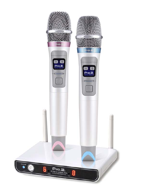
Digital Wireless Microphone System
DWM1
Pro.2
User Manual
Main Features
**This is the first kind of microphone created with 2.4G Digital Wireless
Technology, avoiding interferences issues commonly stipulated in wireless
microphone before successfully that you can enjoy high-quality sounds now.**
z DWM1 is equipped with thick and solid bass and clear pitch that highly sensitive
sound head enables presentation of genuine human voice which is applicable to
multiple purposes such as singing, giving speech, conference and teaching.
z First innovative 2.4G Digital Wireless Technology in Industry is used for
no-harassment in management of channels with audio quality in perfection
rendered!
z 2.4G Digital Wireless Technology is featured with its high-speed transmission
and 60m linear reception.
z None of interference issues incurred with multiplayer in one room because of its
capability of 3 sets wireless microphone system extended.
z Volume Adjuster is uniquely attached that + - buttons on the microphone enables
to adjust volume remotely with ease; the thoughtful installation of switch at
thumb grip under ergonomic design enables switch on/off only via pressing
buttons.
z The exterior streamlined design, in line with visible pearl white paint and further
thermal UV treatment, is free of paint falling everlastingly which highlights its
high quality.
z The dustproof net, made of high-stiffness of steel, presents higher level of
protective effects from extremely precise electroplating treatment and coating on
the surface; the closely integrated design in the sound head and net head of
microphone is excellent in drop and shock resistance which significantly reduces
extra sound generated from shakes.
z 2.4G Technology is featured on its extremes of energy saving; wireless
microphone powered from common kind of alkaline battery(1.5V AAA x2) is
endurable more than 35 hours successively.
z Design of Energy Saving:10 minutes putting aside without any sound input will
power off the microphone; function of low-pressure alert will turn the switch
light to red while the battery is running out.
z Function of LED expressions on volume and digital number on receiver makes it
be in easier and faster operation.
z Mini Antenna at unique design reduces more chances in damages of bending; it
can be rotated at 180 degree and folded up at 90 degree which makes storage be
simpler.
z The ultra-thin design of mini receiver at 200g enables you to hand carry in
convenience or include it into decoration at home simply.
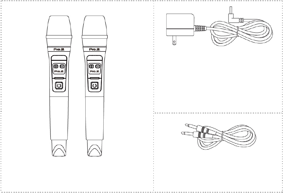
Product Info
--
(3) 5V DC Power Supply
(In put 100~240V)
(1) DWM1-Digital Wireless Microphone
(4) ψ6.3mm Gold-Plated Plug with
Double Needles
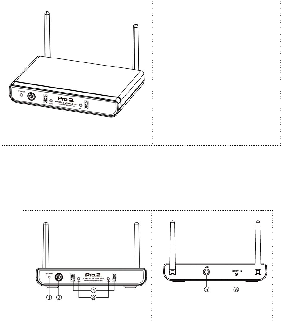
z DWM1 Digital Receiver
I. Introduction to Parts
Front Side
Back Side
1. Power ON/OFF Light(Power):Blue light is on when it is powered on.
2. Power Switch﹕Power ON/OFF the Receiver.
3. Match Button on Microphone(MC1、MC2): It is used for match between
microphone and receiver
4. Volume Light:Expressed in red LED digit number, control the volume through
wireless microphone; Volume range is 0~9; 0 refers to mute and 9 refers to largest.
5. Audio Output Hole (MIC):ψ6.3mm audio output hole, connects receiver to power
amplifier or input surfaces such as mixer, karaoke machine through transmission
line.
6. Power Input Hole:Connect Power Supply and Input power at 5V(DC).
(2) DWM1-Digital Wireless Receiver

II. Installation and Operation of Receiver:
1. Connection of Power Input:Connect input side of 5V(DC)Power Supply to
power input hole and connect the other side to AC Power Outlet
(Note:AC Power spec of POWER SUPPLY must fit with voltage range locally)
2. Connection of Audio Output:Connect ψ6.3mm Plug with Double Needles to Audio
Output Hole of Receiver(MIC) and connect the other side to Power Amplifier or
other input surfaces of mixer (MIC IN).
(Note:Please connect both sides of ψ6.3mm Plug with double needles well, then,
power on Power Amplifier or other machines with audio input, such as mixer. It
is to avoid any temporary sound of contact while in connection between machines
such as Power Amplifier or Mixer and ψ6.3mm Plug with double needles)
3. Power on and activate the projector; blue light is on.
III. Precaution
1. The receiving frequency is best while the antenna is installed at 90 degree vertical
to the ground.
2. The receiver enables with 3 sets of wireless microphone system, but need to follow
with dealer’s instruction of systems without interferences.
3. To avoid frequency interferences, please place it away from microwave and WIFI
Host.
4. Do not use and store it in thermal, humid places with dust and place it apart from
child below 3.
5. Do not drop it down and collide by force to avoid damages of interior circuit board.
6. If it is dirt, wipe it with soft cloth; organic solvent classified as chemical product is
prohibited.
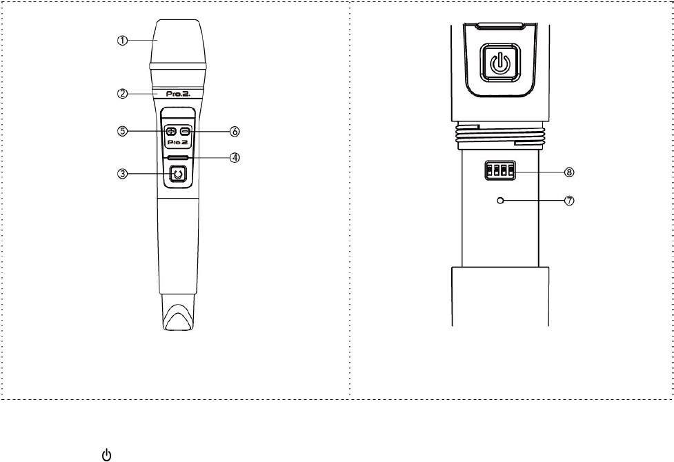
z DWM1 Digital Wireless Microphone
I. Introduction to Parts
Diagram of Front Side
Partial Enlargement of Match Key and
Frequency Key
1. Net Head of Microphone
2. Metal Trims:Classified into blue and pink
3. Power Switch( ):Power ON/OFF in 2~3 seconds of press
4. Power Light:Green is on while it is powered on; Red is on means to replace it wit
new batteries.
5. Vo l u m e K e y -:Press it lightly to decrease the volume of microphone.
6. Vo l u m e K e y +:Press it lightly to increase the volume of microphone.
7. Match Key:It is used for match between projector and receiver
8. Frequency Key:Adjust range of applicable frequency to avoid interferences from
transmission of same frequency.
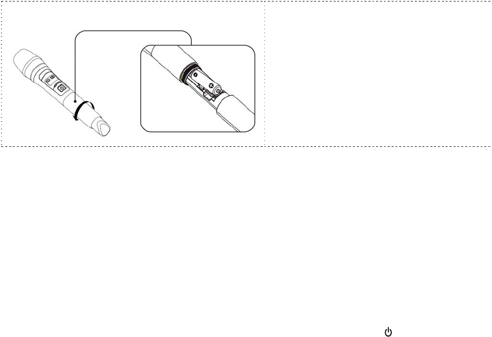
II. Battery Installation
1. As shown on above chart:Rotate bottom side of microphone counterclockwise
until the sleeve is removed.
2. Please put into 2 batteries (1.5V AAA Alkaline or Rechargeable Battery) correctly
into the battery compartment that negative pole is toward the net head.
3. Rotate the bottom side of microphone back clockwise once Item 2 is done.
4. The batteries shall be removed if not use microphone for a long time, avoiding
damages of springs and circuit inside arisen out of battery fluid flowed.
III. Operation
Frequency of projector and microphone has been matched while in delivery, please
operate as follows:
1. Power on the microphone by press POWER Switch of microphone lightly for ( )
1~2 seconds. At this time, the green light is on. AT the mean time, volume light
of receiver is on, referring to volume of microphone. (Note:If the volume light is
off, means receiver and microphone is not match which needs to be done anew)
2. Please operate as follows for matching microphone anew:
a. Power on the receiver and projector; remove bottom side of microphone.
b. Press match key of microphone for 3~5 seconds until power light is flashing, then,
press match keys of receiver(MC1 or MC2) for 3~5 seconds that the receiver is
entering into status of searching frequency now. When the volume light of
receiver is on, means they are matched.
c. Under normal situation, the operation can be done within 15 seconds.
IV. Troubleshooting
If any interferences in your microphone, please operate as follows:
FM SW Rank LF (MHz) HF
(MHz)
0000 0 2404 2444
0001 1 2406 2448
0010 2 2408 2450
0011 3 2410 2452
0100 4 2412 2454
0101 5 2414 2456
0110 6 2416 2458
0111 7 2418 2460
1000 8 2420 2462
1001 9 2422 2464
1010 10 2424 2466
1011 11 2426 2468
1100 12 2428 2470
1101 13 2430 2472
1110 14 2432 2474
1111 15 2434 2476
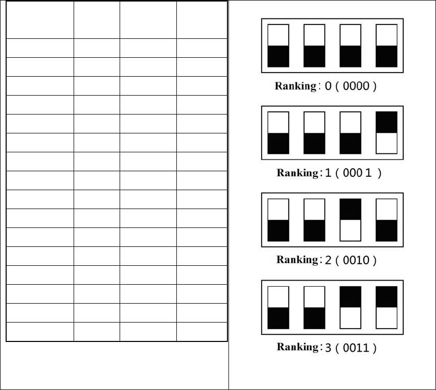
Ranking List
Frequency Key: Diagram of Ranking
1. Rotate bottom side of microphone counterclockwise until it is removed.
2. Buttons up and down to adjust frequency of microphone (Key Up: 0; Key Down:
1).
3. 3 ranks difference is set among frequency of every microphone (Ex: Microphone
A is 0000, and Microphone B will be 0011; you can refer to Ranking List for
desirable one).
V. Precaution
1. Do not use and store it in thermal, humid places with dust and place it apart from
child below 3.
2. Do not drop it down and collide by force to avoid damages of interior circuit board.
3. If it is dirt, wipe it with soft cloth; organic solvent classified as chemical product is
prohibited.
**Without prior approval, corporation, legal entity or user is not allowed to alter frequency,
enlarge power or change designed feature or function on low-power radio with types
certified in accreditation.
The application of low-power radio shall not influence safety in the flight and cause negative
impacts on legal communication; stop using if in event of interference until it is improved.
Low-power radio must bear with interference from legal communication or wave radiated &
electronic equipments specified for industry, science and medical fields. **
Federal Communication Commission Interference Statement
This equipment has been tested and found to comply with the limits for a Class B
digital device, pursuant to Part 15 of the FCC Rules. These limits are designed to
provide reasonable protection against harmful interference in a residential installation.
This equipment generates, uses and can radiate radio frequency energy and, if not
installed and used in accordance with the instructions, may cause harmful interference
to radio communications. However, there is no guarantee that interference will not
occur in a particular installation. If this equipment does cause harmful interference to
radio or television reception, which can be determined by turning the equipment off
and on, the user is encouraged to try to correct the interference by one of the
following measures:
. Reorient or relocate the receiving antenna.
. Increase the separation between the equipment and receiver.
. Connect the equipment into an outlet on a circuit different from that to which the
receiver is connected.
. Consult the dealer or an experienced radio/TV technician for help.
FCC Caution: To assure continued compliance, any changes or modifications not
expressly approved by the party responsible for compliance could void the user's
authority to operate this equipment. (Example - use only shielded interface cables
when connecting to computer or peripheral devices).
FCC Radiation Exposure Statement
This equipment complies with FCC RF radiation exposure limits set forth for an
uncontrolled environment.
This transmitter must not be co-located or operating in conjunction with any other
antenna or transmitter.
This device complies with Part 15 of the FCC Rules. Operation is subject to the
following two conditions:
(1) This device may not cause harmful interference, and (2) This device must accept
any interference received, including interference that may cause undesired operation.