OCEASOFT MOD THE WAVECARD RECEIVER MODEM COLLECT DATA TRANSMITTED BY END-POINT MODULES AND FORWARD IT TO THE MANAGEMENT SOFTWARE User Manual WaveCard user handbook
OCEASOFT THE WAVECARD RECEIVER MODEM COLLECT DATA TRANSMITTED BY END-POINT MODULES AND FORWARD IT TO THE MANAGEMENT SOFTWARE WaveCard user handbook
OCEASOFT >
Users Manual

Document : XTLMOD -UserMan.sxw
XLTMOD Handbook page 1 of 74
XLTMOD
User Manual
Document : XTLMOD -UserMan.sxw
REVISIONS HISTORY
Rev. # Description Auteur Date Commentaires
1 Original document PGN 19/09/08 Version 1
➢FIRMWARE VERSIONS OF SUPPORTED XLTMOD
WaveCard 25mW : Compatible with the version v2.01, and later
This device complies with part 15 of the FCC rules. Operation is subject to the
following two conditions : this device may not cause harmful interference, and
this device must accept any interference received, including interference that
may cause undesired operation.
Caution : any changes or modifications not expressly approved by Coronis-
Systems could void the user's authority to operate the equipment.
XLTMOD Handbook page 2 of 74

Document : XTLMOD -UserMan.sxw
TABLE OF CONTENTS
1. INTRODUCTION..........................................................................................................................................5
2. RS232 SERIAL PROTOCOL PRESENTATION............................................................................................6
2.1- Exchanges principle...........................................................................................................................6
2.1.1 - Low level acknowledge................................................................................................................6
2.1.2 - Request/ Response principle.......................................................................................................7
2.2- Exchanged frames format.................................................................................................................8
2.2.1 - Wake Up and synchronization mechanism..................................................................................8
2.2.2 - Frame description........................................................................................................................8
2.3- Commands description....................................................................................................................10
2.3.1 - Control type commands.............................................................................................................10
2.3.2 - Applicative type commands.......................................................................................................10
2.3.3 - Service type commands.............................................................................................................12
3. SETTING THE INTERNAL PARAMETERS OF THE WAVECARD............................................................13
3.1- Configuration of the functional parameters...................................................................................13
3.1.1 - Format of the internal parameters access.................................................................................14
3.1.2 - Wake Up and synchronization mechanism................................................................................17
a) Principle when transmitting, or receiving a frame.........................................................................................17
b) Example describing a point-to-point exchange of the type Request / Response.........................................19
3.2- Configuration of the control parameters........................................................................................20
3.2.1 - selection of the radio operating channel when FHSS is deselected...........................................20
a) reading commands format of the channel used............................................................................................20
b) Writing commands format of the channel to use...........................................................................................21
3.2.2 - Selection of the RF medium physical mode..............................................................................22
a) reading commands format of the physical layer mode..................................................................................22
b) selection commands format of the physical layer mode to use....................................................................23
c) Automatic selection of Radio physical mode to use......................................................................................23
3.2.3 - Selection of the radio board emission power.............................................................................24
a) selection commands format of the emission power......................................................................................24
b) reading commands format of the emission power........................................................................................25
3.2.4 - Activation of the Wavenis RF Asic RSSI threshold autocorrection.............................................26
a) Modification commands format of the RSSI threshold autocorrection state ................................................26
b) Reading commands format of the RSSI threshold autocorrection state ......................................................27
3.2.5 - Selection de la vitesse de transmission série.............................................................................28
a) Selection commands format of the baudrate................................................................................................28
3.2.6 - Reading the firmware version of the WaveCard.........................................................................29
a) Commands format.........................................................................................................................................29
3.2.7 - Reading the RSSI level (Received Signal Strengh Indicator)...................................................30
a) Commands....................................................................................................................................................30
b) Format of the commands...............................................................................................................................31
3.2.8 - TEST Mode................................................................................................................................32
a) Command......................................................................................................................................................32
b) Format of the command................................................................................................................................32
4. SERVICE COMMANDS..............................................................................................................................33
4.1- Description of the commands, and their formats..........................................................................33
XLTMOD Handbook page 3 of 74

Document : XTLMOD -UserMan.sxw
4.2- Request types...................................................................................................................................34
4.3- Presence detection principle between WAVECARD......................................................................35
5. COMMUNICATION MODES.......................................................................................................................36
5.1- 'Frame Exchange’ Mode...................................................................................................................36
5.1.1 - Configuration of the parameters relating to the 'Frame Exchange' mode..................................36
5.1.2 - Description of the commands, and their formats........................................................................37
5.1.3 - Use of the Relaying mode..........................................................................................................38
a) On frame transmission..................................................................................................................................38
b) On frame reception........................................................................................................................................38
5.1.4 - Time-out management...............................................................................................................41
5.2- 'Message’ Mode................................................................................................................................43
5.2.1 - Configuration of the parameters relating to the 'Message' mode...............................................43
5.2.2 - Description of the commands, and their formats........................................................................43
5.2.3 - Use of the Relaying mode..........................................................................................................45
a) On frame transmission..................................................................................................................................45
b) On frame reception........................................................................................................................................45
c) Diagram of the relaying mode.......................................................................................................................46
5.3- ’Polling’ Mode..................................................................................................................................49
5.3.1 - Configuration of the parameters relating to the 'Polling' mode...................................................49
5.3.2 - Description of the commands, and their formats........................................................................50
5.3.3 - Difference between selective, and not-selective Polling mode...................................................51
5.3.4 - Diagram of an exchange in polling mode...................................................................................54
5.4- ’Broadcast’ mode............................................................................................................................56
5.4.1 - Configuration of the parameters relating to the 'Broadcast' mode..............................................56
5.4.2 - 'BroadCast' mode without waiting for a response......................................................................56
a) Description of the commands........................................................................................................................56
b) Example of operations during a broadcast exchange, without waiting for responses..................................57
5.4.3 - 'BroadCast' mode with waiting for responses.............................................................................57
a) Description of the commands........................................................................................................................57
b) Example of operations during a broadcast exchange, with waiting for responses.......................................58
5.4.4 - Format of the commands – from the request transmitter side...................................................59
5.4.5 - Format of the commands – from the request receiver side........................................................60
5.4.6 - Use of the selective, or not-selective broadcast mode...............................................................60
5.5- ’Multi frames' Mode..........................................................................................................................61
5.5.1 - Principle.....................................................................................................................................61
5.5.2 - Format of the received frames...................................................................................................61
APPENDIX 1 : Mechanical description of the WAVECARD........................................................................62
APPENDIX 2 : Electric interface of the WAVECARD...................................................................................64
APPENDIX 3 : List of the functional parameters........................................................................................65
APPENDIX 4 : List of the commands of parameters setting.....................................................................66
APPENDICE 5 : List of the commands of data transmission....................................................................67
XLTMOD Handbook page 4 of 74
Document : XTLMOD -UserMan.sxw
1. INTRODUCTION
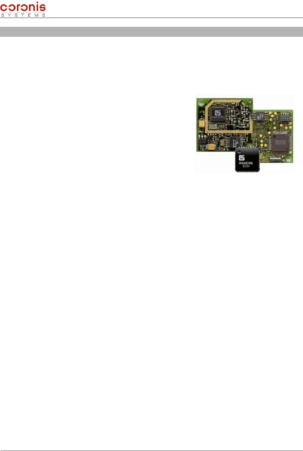
The XLTMOD is based on a Wavecard 25 mW.
The WAVECARD equipment acts like a RS232 Radio frequency gateway.
This device is driven through a USART link (RS232 or TTL) by a client application (called HOST in the
continuation of this document) embedded on a microcontroller or on a PC equipment.
The main features of the WAVECARD are :
to send a frame on the RF medium depending on Host equipment
to inform Host equipment about received frame
Exchanges between two WAVECARD require that each one is
connected to a Host device.
However, Wavecard can process some specific frames without Host
connected. These exchanges are called Service Exchanges and are
mainly used for installation and maintenance procedures.(cf. §4).
The purpose of this document is to present:
the low level of the exchange protocol to drive the Wavecard radio board through an
asynchronous serial RS232 interface (±12V) or compliant with TTL level (0-3V) ;
the electrical interface of the Wavecard radio board ;
the mechanical interface of the Wavecard radio board ;
This document serves as a specification to drive a DLL driving library on PC environment in the case the
Wavecard radio board is used as a RF Modem either to be integrated in a existing electronic device or to be
driven by a specific CPU mother board.
This document is also useful for the Waveport equipment. Waveport is a PC connected oriented RF modem
based on the Wavecard.
In this document the Host term is used to speak about the equipment or sub-equipment that is driving the
Wavecard radio board. The radio board term indicates the Wavecard equipment .
XLTMOD Handbook page 5 of 74
Document : XTLMOD -UserMan.sxw
2. RS232 SERIAL PROTOCOL PRESENTATION
This protocol is dedicated to an asynchronous RS232 or TTL link between the host and the radio board.
➢Transmission format :
8 bits data,
1 stop bit,
no parity
➢Transmission speed : 9600 baud (contact us for other speed : marketing@coronis-systems.com)
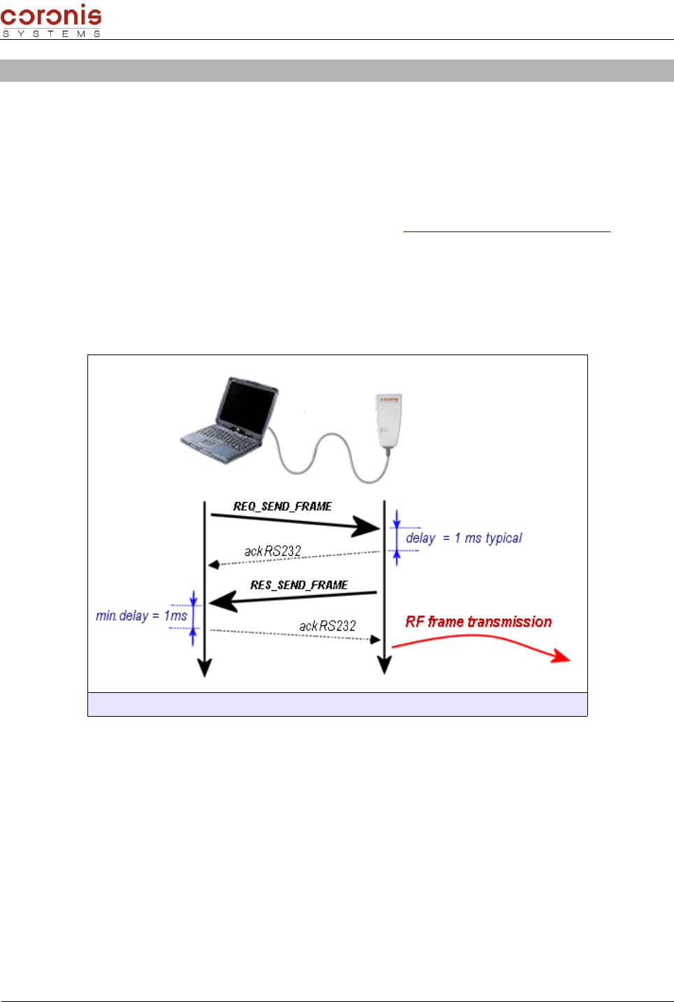
2.1- Exchanges principle
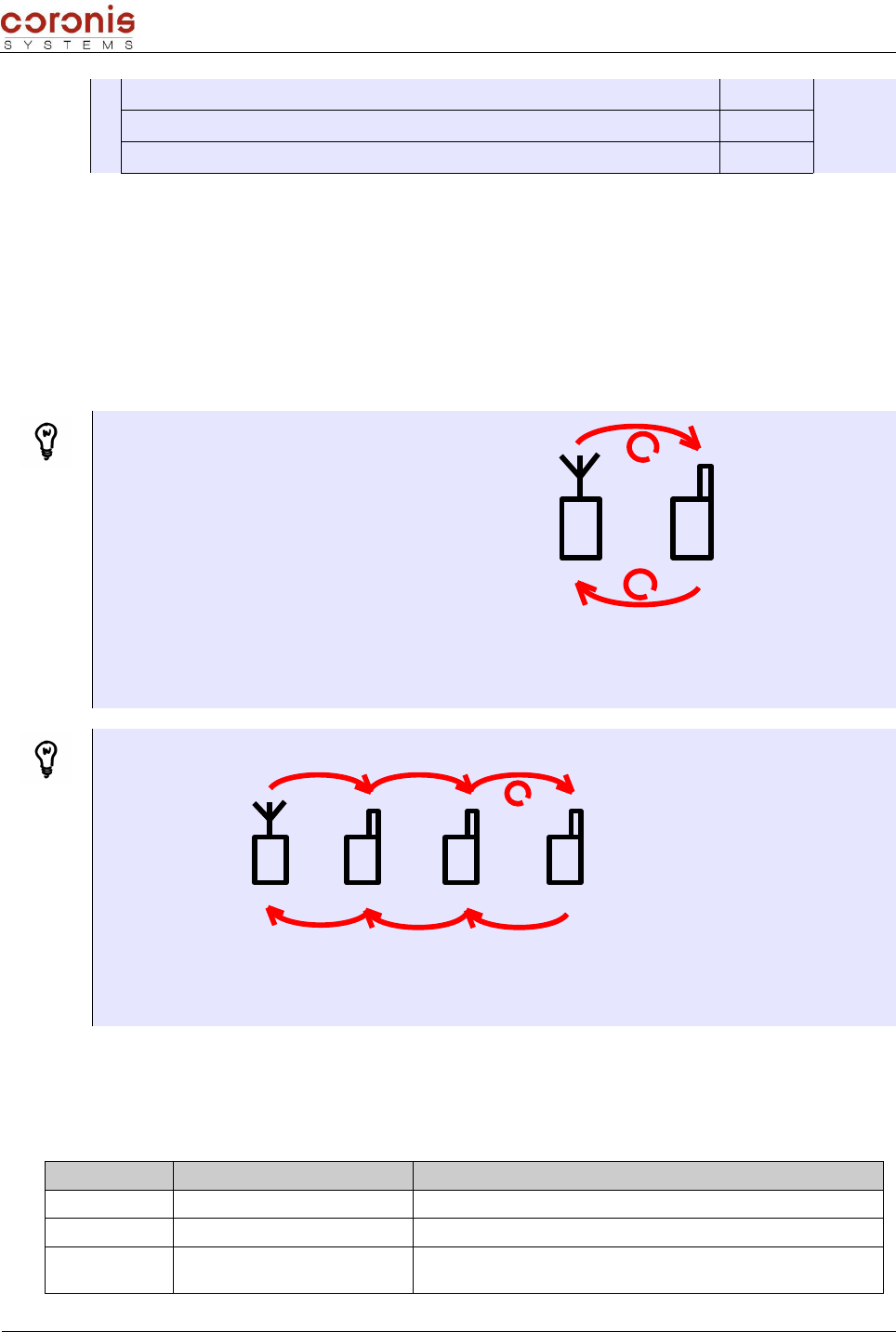
The host or the radio board can take the initiative of the exchange. Nevertheless in the high majority of the
cases, the host will take the initiative.
Fig. 1 – synoptic of the exchanges between a WavePort modem, and its host
2.1.1 - Low level acknowledge
In all the cases, the serial frames exchanged between the host and the radio board are managed by an
acknowledge mechanism.
A minimum latency time of 1 ms must be respected between the frame reception and the corresponding
acknowledge emission in order to respect the radio board processing time after a frame reception.
If the Acknowledge frame is not received by the initiator, it can decide to re-send several times the frame
(retries mechanism). The RF default setting is :
Time-out = 500 ms
repetition number = 3
XLTMOD Handbook page 6 of 74
Document : XTLMOD -UserMan.sxw
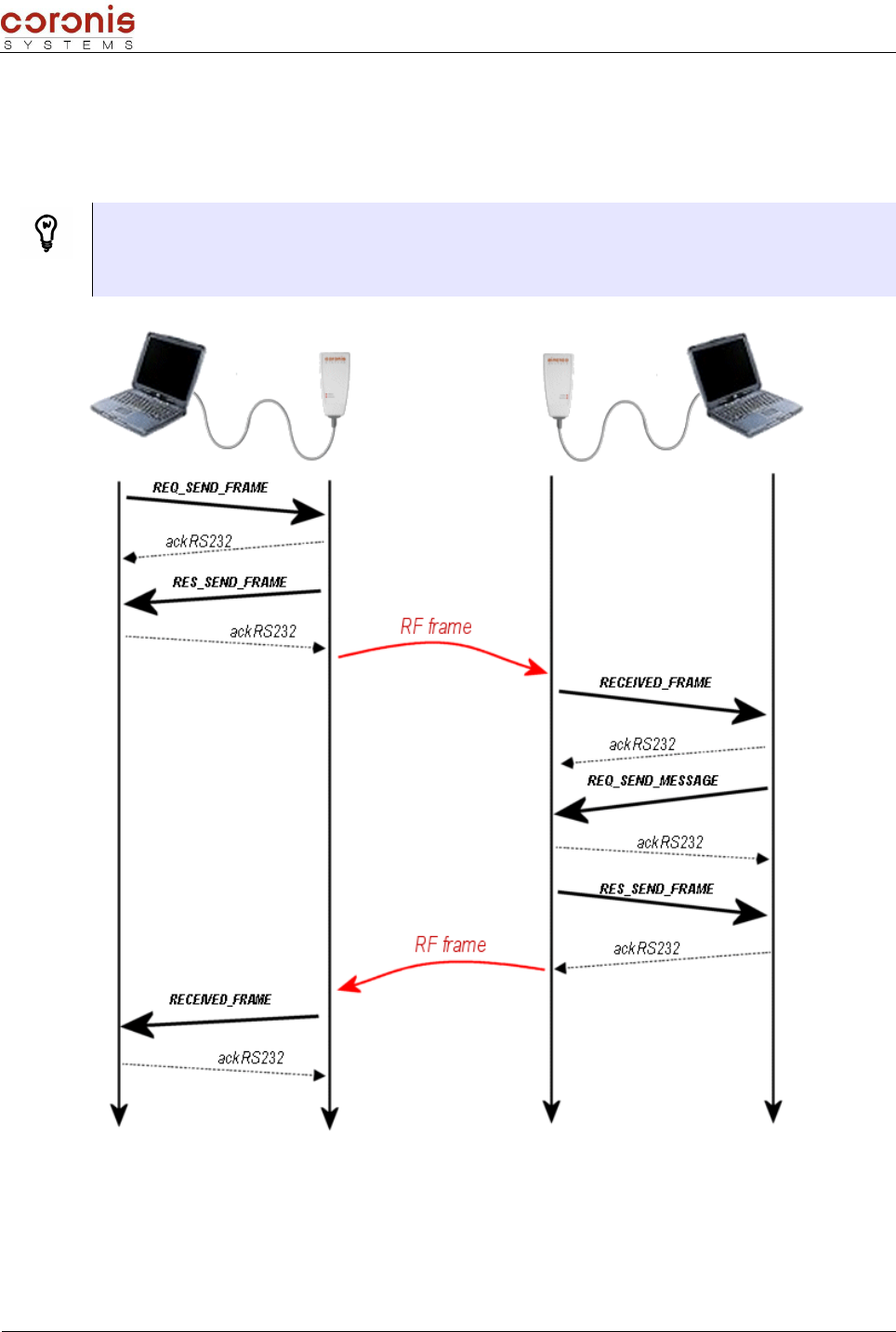
2.1.2 - Request/ Response principle
Some exchanges need a Request/response mechanism.
In this case , an high level acknowledge (RES prefix command) is initiated by the RF board following the
request frame (REQ prefix command) sent by the host.
The request frame are identified by REQ_XXX_XXX
example : REQ_SEND_FRAME
The high level acknowledge frame are identified by RES_XXX_XXX
example : RES_SEND_FRAME
In this example, from the request transmitter side, the frame RECEIVED_FRAME is the response associated
to the request REQ_SEND_FRAME.
The high level acknowledgement of the request is identified by the RES_SEND_FRAME frame.
XLTMOD Handbook page 7 of 74

Document : XTLMOD -UserMan.sxw
2.2- Exchanged frames format
2.2.1 - Wake Up and synchronization mechanism
In the purpose to optimize power consumption, the Wavecard is in a STANDBY mode and is wakening up
either :
periodically to poll a radio activity ;
on a serial frame reception coming from the host equipment.
A synchronization character is needed before the data in the serial frame to give time to the radio board to
wake up. This character is in hexadecimal notation : 0xFF.
To be homogeneous, the radio board precedes as well its frames emissions with this synchronization
character.
2.2.2 - Frame description
The frames format is standardized as following :
SYNC STX LENGTH CMD DATA CRC ETX
1 byte 1 byte 1 byte 1 byte De 0 à 250 bytes 2 bytes 1 byte
Synchro.
character
Start of
transmission
character
Frame
length Command Data
Control
Redundancy
Check
LSB First
End of
transmission
character
0xFF 0x02 0x03
LENGTH
Note : - The frame minimum size is 6 bytes.
- The frame maximum size is 256 bytes.
The frame length (byte LENGTH) is computed from its own position until the included CRC. Bytes
SYNC, STX and ETX are not included in the length.
To insure transmitted information integrity between the host and the radio board, a CRC code on 16 bits is
computed on overall frame data excepted STX and ETX characters ( the byte LENGTH is inserted in the
CRC).
The CRC code is computed by a division of the frame binary sequence by the following polynomial:
X16 + X12 + X5 + 1
A coding example is indicated on the next page.
XLTMOD Handbook page 8 of 74

Document : XTLMOD -UserMan.sxw
CRC principle coding in C language :
#include <iostream.h>
#include <stdio.h>
#include <string.h>
void main ( )
{
int Poly = 0x8408;
int lg = 9;
unsigned int Frame [] = { 0x0B, 0x20, 0x43, 0x06, 0x01, 0x00, 0x00, 0x02, 0X01};
unsigned int Crc;
int j, i_bits, carry;
Crc = 0;
for ( j=0 ; j < lg ; j++ )
{
Crc = Crc ^ Frame[j] ;
for ( i_bits=0 ; i_bits < 8 ; i_bits++ )
{
carry = Crc & 1 ;
Crc = Crc / 2 ;
if ( carry )
{
Crc = Crc ^ Poly;
}
}
}
printf ( “CRC = %x “, Crc);
}
The computed CRC is the following : 41D2 hexadecimal
Then LSB byte and MSB byte must be inverted before storage in the frame.
This example allows to compute a CRC on a fix frame length equal to 9.
XLTMOD Handbook page 9 of 74

Document : XTLMOD -UserMan.sxw
2.3- Commands description
All the frames circulating on the serial bus are formatted as described in chapter 2.2.2. The distinction
between the various frames is carried out via the 'CMD' fields representing the command (or the action) to
carry out.
The available commands types can be classified in three parts :
Control type commands
Applicative commands
Service type commands
2.3.1 - Control type commands
This commands are used for the low level acknowledgement of the serial frames.
CMD NAME DESCRIPTION DATA FIELD FORMAT
0x06 ACK
Acknowledge Frame :
Sent by the receiver after reception of a Request /Response
frame type supported and understood.
No data field.
0x15 NAK
Non Acknowledge Frame :
Sent by the receiver after reception of a Request /Response
frame not understood.
No data field.
0x00 ERROR
Error frame :
Sent by the receiver after reception of a Request/response
frame understood but not supported.
Byte 1 :
0x01 : unknown command.
2.3.2 - Applicative type commands
The applicative type commands use the Request/response mechanism.
We distinguish two parts in the applicative type commands : the commands relating to the parameter setting
and the configuration of the board ; and in addition the commands relating to radio exchanges.
➢Commands relating to the parameter setting
Read, or update the internal parameters,
Read, or select the radio operating channel when FHSS is deselected,
Read, or select the RF medium physical mode,
Read, or select the radio board emission power,
Activation of the Wavenis RF Asic RSSI threshold autocorrection,
Modification of the serial link baudrate,
Reading the RSSI level of a distant equipment,
Reading the RSSI level of the wavecard, following an exchange with a distant equipment,
Reading the firmware version of the WaveCard,
Set the WaveCard into a test mode.
XLTMOD Handbook page 10 of 74

Document : XTLMOD -UserMan.sxw
➢Commands relating to radio exchanges
The radio exchanges are composed of several modes of transmission/reception. With in certain cases, the
possibility of receiving several consecutive radio frames (multi frames mode, accessible in reception only).
The following modes allow point-to-point exchanges :
’Frame Exchange’ mode : This mode allows to emit a request, with waiting of a radio response
from the distant equipment.
Following the radio frame sending, the Wavecard radio board stay in radio reception during a time
(fixed by default at 2s, cf. RADIO_USER_TIMEOUT) in order to receive the response from the
addressed equipment. During this time the serial RS232 link is not managed. This command is
particularly intended to read CORONIS SYSTEMS radio modules used to collect remote information
(temperature, humidity, meters index, ...).
‘Message’ mode : allows to emit a request, without waiting of a radio response from the distant
equipment.
After radio frame emission, the Wavecard radio board is listening again the serial RS232 link. This
command is suited to a simple data transfer between several Wavecard equipments.
Moreover exchanges of the point-to-point types have an additional mode which allow to reach a module out
of radio range of the transmitter, by relaying the frames via other equipments.
'Relaying' mode : this functionality allow to use a radio equipment to repeat a frame which is not
initially intended to him.
This functionality is used when the transmitter equipment, and the recipient of the request are out of
radio range. The maximum number of repeaters is limited to 3.
The remaining modes allow exchanges with several distant equipments, in a selective way or not.
‘Polling’ mode : allows to address a request to a list of known distant equipment. The response
is sent to the host, transmitter of the request, when all the distant equipment responded, or on time-
out.
In this case, the list of the distant equipments is configured via a command of parameter setting (see
chapter 3)
’Broadcast’ mode : allows to address a request to all the distant equipment within radio range
of the transmitter, or only to a group of equipment in radio range of the transmitter.
Particular Case: multi-frames reception
Multi frame mode allows multi frame exchange between the Wavecard/Waveport (considered like the
master of the exchange) and one of the telemetry equipments of the Coronis Systems product family
( WaveTherm, WaveFlow, WaveSens, ...).
Current version of Wavecard does not allow multi frame mode between two Wavecard/Waveport
equipments.
XLTMOD Handbook page 11 of 74

Document : XTLMOD -UserMan.sxw
2.3.3 - Service type commands
Services commands are used to configure the Wavecard or to read radio parameters independently of the
connected host equipment.
When the wavecard recognizes Service command, no data are sent to the connected host.
These commands are mainly used to:
Process detection of a distant RF equipment
Process a link budget with a distant equipment (RSSI level detection)
Process the setting of parameters by RF way
the details of the frame format, and its usage is described in chapter 4.
XLTMOD Handbook page 12 of 74

Document : XTLMOD -UserMan.sxw
3. SETTING THE INTERNAL PARAMETERS OF THE WAVECARD
The internal parameters of WaveCard are declined in two categories :
parameters of control (emission power level, channel selection, etc...) carried out by specific
frame of type Request/Response. this parameters allows to modify the mode of communication
(either serial, and RF).
Functional parameters (WakeUp period, group number, etc...) carried out by the same frame of
writing of internal parameters. this parameters allows to modify the behavior of WaveCard,
according to the type of radio exchange used.
Attention, the setting parameter commands apply only to a local WaveCard, not to a distant one.
3.1- Configuration of the functional parameters
The functional parameters are directly related to the default operation of WaveCard, and to the types of radio
exchanges used. I.e. according to the type of radio exchange which will be used, the functional parameters
will have to be initialized.
Default values are set at the first initialization of the product.
Paramet
er
number
Description Value Size
(in
byte)
0x00 AWAKENING_PERIOD : polling period of RF
medium radio, in multiples of 100ms
Period in multiples of 100ms
(by default, 0x0A for one second)
0 = quasi-permanent reception (every
20ms)
1
0x01 WAKEUP_TYPE : Wake Up type used during a
frame emission
0 : long Wake Up (default setting)
1 : short Wake Up = 50 ms 1
0x02
WAKEUP_LENGTH : duration of the Wake up
when long wake up is set up.
This value must be higher than the polling
period of RF medium radio.
Value in multiples of 1ms, defined LSB first
Default value : 1100 ms
min value = 20 ms (0x1400)
max value = 10 sec. (0x1027)
2
0x03 WAVECARD_POLLING_GROUP : Byte containing
the Polling Group of the Wavecard.
Byte 1 : Polling_Group
by default, Polling_Group = 0x00 1
0x04
RADIO_ACKNOWLEDGE : indicates if the radio
frames must be acknowledged by the
receiver.
0 : no acknowledge (default value)
1 : acknowledge used 1
0x05 RADIO_ADDRESS : radio board address
This Value is issue from the
manufacturing.
In Reading only
6
0x06
RELAY_ROUTE_STATUS : Parameter relative to
Relay route transmission in each relayed frame
received
0x00 : Relay route transmisson
deactivated
0x01 : Relay route transmission
activated
by default, Relay route transmisson
deactivated
1
XLTMOD Handbook page 13 of 74

Document : XTLMOD -UserMan.sxw
0x07
RELAY_ROUTE : Table containing the radio
addresses for successive repeaters to use to
reach the final equipment.
BYTE 1 : number of repeaters in the
route
Maximum repeater number = 3
Si BYTE 1 != 0
BYTES 2 à 7 : First repeater radio
address
…, and so on.
1 à 19
0x08 POLLING_ROUTE : Table containing the list of
modules radio address to be addressed.
BYTE 2 : number of equipments to
interrogate
IF BYTE 2 != 0
BYTES 3 to 8 : radio address of the first
module..., and so on.
1 à
241
0x09
GROUP_NUMBER : Byte containing the number
of the group of radio equipment to address in
radio polling mode.
Group number
by default, GROUP_NUMBER = 0x00 1
0x0A POLLING_TIME : delay between two
consecutive emission in polling mode
Value in multiples of 100ms
By default, POLLING_TIME = 0x0A 1
0x0C RADIO_USER_TIMEOUT : time-out used for the
reception of a response frame
Value in multiples of 100ms
default value = 0x14 (2 seconds) 1
0x0E EXCHANGE_STATUS : parameter relative to the
error or status frame management activation.
0 : status and error frame deactivated,
1 : error frame activated,
2 : status frame activated,
3 : both status and error frames
activated,
by default, RECEPT_ERROR_STATUS =
0x00.
1
0x10
SWITCH_MODE_STATUS : automatic selection
of Radio physical mode used to address an
equipment depending on radio address
0 : automatic selection deactivated
1 : automatic selection activated
Default value, SWITCH_MODE_STATUS =
0x00
1
0x16
WAVECARD_MULTICAST_GROUP : Byte
containing the Multicast Group of the Wavecard
(available from V2.00 version ).
By default, no group selected = 0xFF 1
0x17
BCST_RECEPTION_TIMEOUT : timeout used for
the reception of CSMA frame consecutively to
REQ_SEND_BROADCAST Command emission
(available from firmware V2.01 version )
Valeur in multiples of100ms.
Default = 0x3C (6 seconds) 1
3.1.1 - Format of the internal parameters access
The Wavecard equipment manage internal parameters mainly relative to RF features. RS232 commands
allow to access these parameters in read or write mode. Default values are set at the first initialization of the
product.
REQ_READ_RADIO_PARAM command is used to read parameters and REQ_WRITE_RADIO_PARAM is
used to write parameters. Each parameter must be accessed individually.
XLTMOD Handbook page 14 of 74

Document : XTLMOD -UserMan.sxw
CMD NOM DESCRIPTION
0x40 REQ_WRITE_RADIO_PARAM Request to update the radio parameters
0x41 RES_WRITE_RADIO_PARAM Response from the radio board to the radio parameters
update
0x50 REQ_READ_RADIO_PARAM Request to read the radio parameters.
0x51 RES_READ_RADIO_PARAM Response from the radio board to a parameters reading.
Remark : In the command byte coding, the Response frame type are taking the Request command
byte value with the LSB bit set to 1.
Data field formats to read or to update the radio parameters is the following :
Request to read the radio parameters
REQ_READ_RADIO_PARAM
HEADER CMD DATA CRC ETX
3 bytes 1 byte 1 byte 2 bytes 1 byte
0xFF ; 0x02 ;
0x05 0x50 Number of the parameter to read 0x03
Response from the radio board to a parameters reading
RES_READ_RADIO_PARAM
HEADER CMD DATA CRC ETX
3 bytes 1 byte 1 byte 1 byte variable 2 bytes 1 byte
0xFF ; 0x02 ;
0xXX 0x51
Status = 0x00 read ok
Status = 0x01 read
error
Parameter number value
-0x03
Request to update the radio parameters
REQ_WRITE_RADIO_PARAM
HEADER CMD DATA CRC ETX
3 bytes 1 byte 1 byte variable 2 bytes 1 byte
0xFF ; 0x02 ;
0xXX 0x40 Number of the parameter to
update Parameter data 0x03
Response from the radio board to the radio parameters update
XLTMOD Handbook page 15 of 74

Document : XTLMOD -UserMan.sxw
RES_WRITE_RADIO_PARAM
HEADER CMD DATA CRC ETX
3 bytes 1 byte 1 byte 2 bytes 1 byte
0xFF ; 0x02 ;
0x05 0x41
STATUS
= 0x00 update OK
= 0x01 update error
0x03
Timeout management : The WaveCard can be considered in fault, beyond the value of the following
latencies:
REQ_WRITE_RADIO_PARAM 2 seconds.
REQ_READ_RADIO_PARAM 2 seconds.
EXAMPLE : configuration of the repeaters table, and activation of error frames.
Between WaveCard (exchange instigator), and the recipient equipment, we have a repeater
equipment(radio address : 0X AA AA AA AA AA AA). In addition, we must authorize the error frame, in order
to determine which distant equipment caused the error.
•
Writing new parameters
repeaters list configuration (Request/Response mechanism)
Request from the host to the WaveCard (
REQ_WRITE_RADIO_PARAM)
HEADER
SYN
CSTX LENGT
H
CMD
DATA
Parameter
number Parameter data CRC ETX
0xFF 0x0
20x0C 0x40 0x07 0x01 ; 0xAAAAAAAAAAAA 0xXXXX 0x03
Response from the WaveCard to the host (
RES_WRITE_RADIO_PARAM)
HEADER
SYNC STX LENGT
H
CMD
DATA
Status of the update
CRC ETX
0xFF 0x02 0x05 0x41 0x00 0xXXXX 0x03
Activation of the error frames (Request/Response mechanism)
Request from the host to the WaveCard (REQ_WRITE_RADIO_PARAM)
HEADER
SYN
CSTX LENGT
H
CMD
DATA
Parameter
number Parameter data CRC ETX
XLTMOD Handbook page 16 of 74

Document : XTLMOD -UserMan.sxw
0xFF 0x02 0x06 0x40 0x0E 0x01 0xXXXX 0x03
Response from the WaveCard to the host (RES_WRITE_RADIO_PARAM)
HEADER
SYNC STX LENGT
H
CMD
DATA
Status of the update
CRC ETX
0xFF 0x02 0x05 0x41 0x00 0xXXXX 0x03
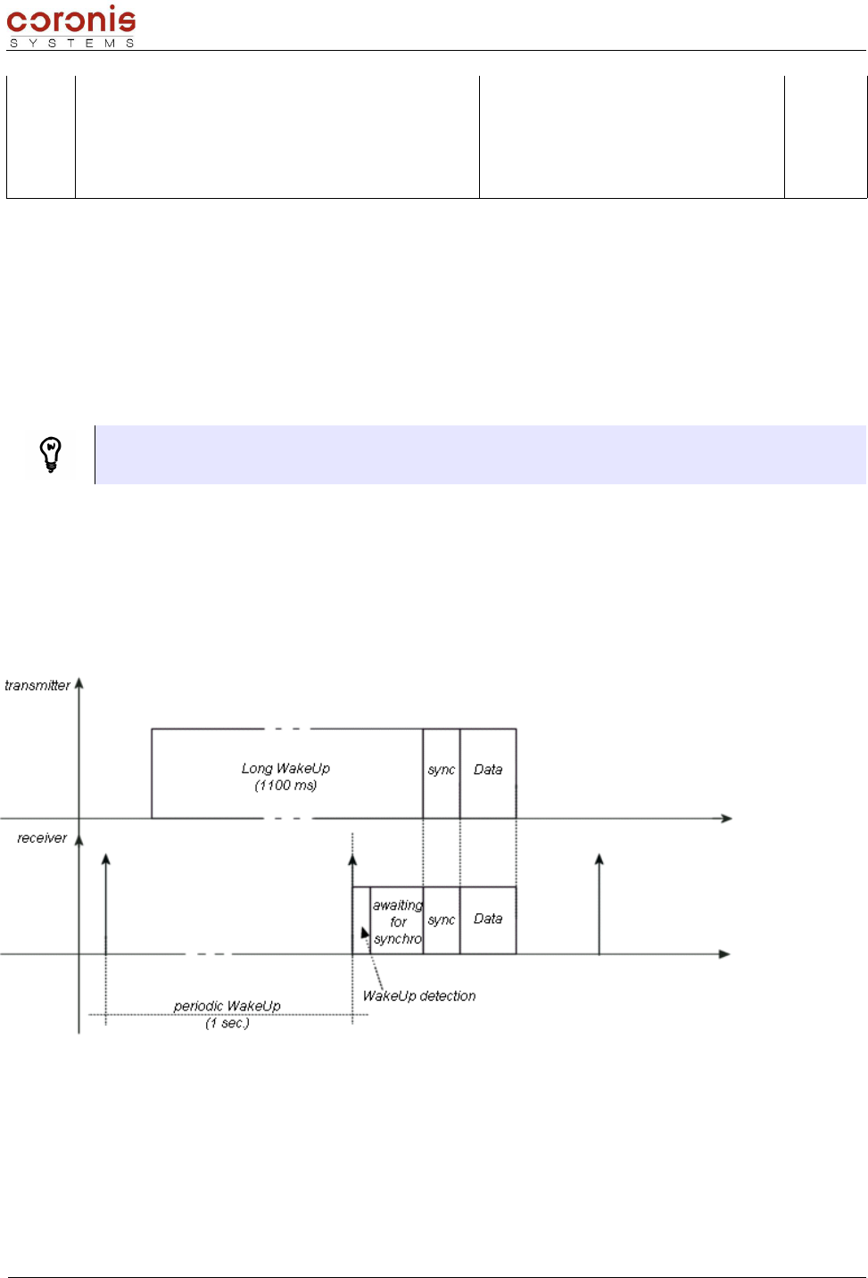
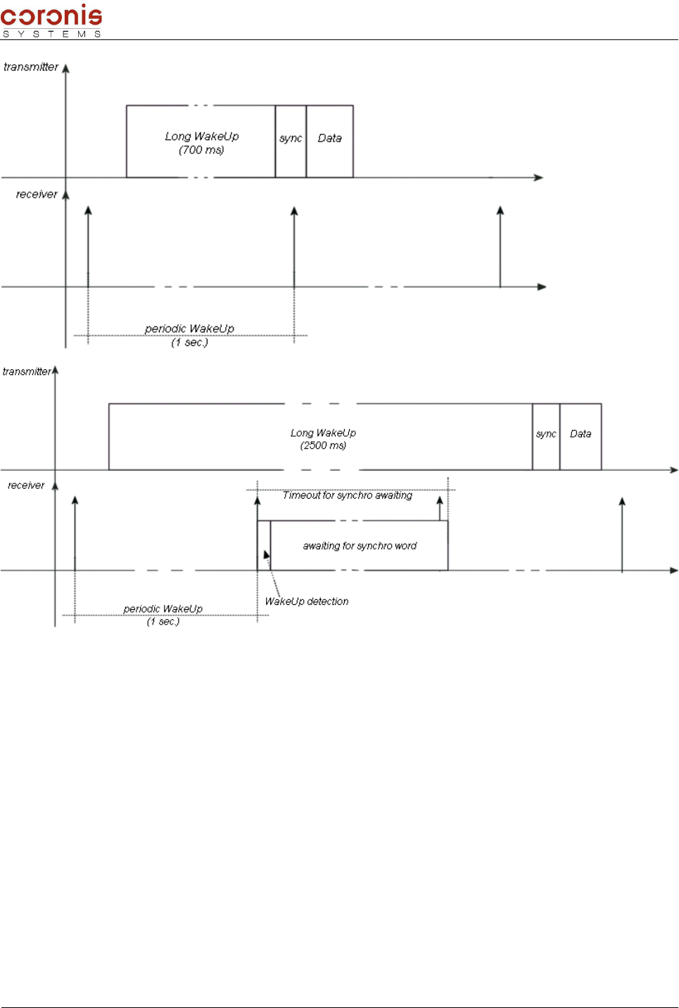
3.1.2 - Wake Up and synchronization mechanism
In the purpose to optimize power consumption, the Wavecard is in a STANDBY mode and is wakening up
periodically to poll a radio activity. The wakeup period is given by the value of the AWAKENING_PERIOD
parameter, expressed in multiples of 100ms (1 second by default).
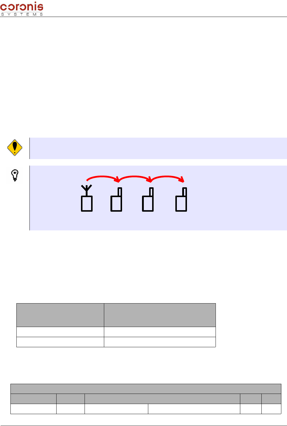
a) Principle when transmitting, or receiving a frame
When transmitting a frame to a distant equipment, the transmitter begins an awakening preamble called
'WakeUp' being used to awake the receiving equipments which will position then in radio reception. This
preamble results in the sending on the radio medium, of a binary succession of symbol.
This awakening preamble (WakeUp) can be of two types,
Long WakeUp : used when transmitting a request towards distant equipment. Its duration can be
parameterized by the user (1100ms by default); and is generally equal to the WakeUp period of
the equipment to address, plus 100ms, in order to avoid transmitting between two periods of
reception.
Short WakeUp : used only when responding to a point-to-point request. Its duration is equal to
50ms, and cannot be configured.
NUM DESCRIPTION VALUE SIZE (in
bytes)
0x00 AWAKENING_PERIOD : polling period of RF medium
radio, in multiples of 100ms
Period in multiples of 100ms
(by default, 0x0A for one second)
0 = quasi-permanent reception (every
20ms)
1
0x01 WAKEUP_TYPE : Wake Up type used during a frame
emission
0 : long Wake Up (default setting)
1 : short Wake Up = 50 ms 1
XLTMOD Handbook page 17 of 74
Document : XTLMOD -UserMan.sxw
0x02
WAKEUP_LENGTH : duration of the Wake up when
long wake up is set up.
This value must be higher than the polling period of
RF medium radio.
Value in multiples of 1ms, defined LSB first
Default value : 1100 ms
min value = 20 ms (0x1400)
max value = 10 sec. (0x1027)
2
The receiver of the exchange, when it detect WakeUp preamble on the radio medium, carries out the
following operations:
It starts a timeout of waiting for the synchronization word (sync), which the duration is slightly
higher than its WakeUp period. This duration cannot be configured.
It begins a validation phase of the WakeUp preamble (detection of WakeUp). This phase
corresponds to the detection of several successive symbols composing the preamble. If the
detection fails, the equipment is repositioned in stand-by mode. The time of detection depends on
the speed transmission used.
The periodic wakeup having to occur when waiting of synchronization, are memorized (in order to
preserve the periodicity), but not carried out.
At the end of the phase of WakeUp, the transmitter equipment send a sequence of synchronization, followed
by data to be transmitted.
➢Typical case (Long WakeUp = receiver WakeUp period + 100ms)
➢Case of too short WakeUp (lower than the receiver WakeUp period)
XLTMOD Handbook page 18 of 74
Document : XTLMOD -UserMan.sxw
➢Case of too long WakeUp (much higher than the receiver WakeUp period)
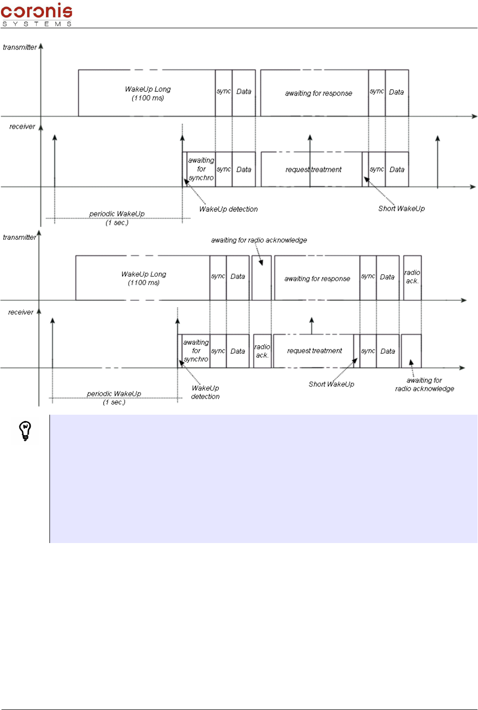
b) Example describing a point-to-point exchange of the type Request / Response.
When using a point-to-point exchange of the type request/ Response, the transmission of the request is
made in the same way that previously. But the transmitter, after the sending of the data, awaits for a
response, during a time which can be configured by the RADIO_USER_TIMEOUT parameter (0x0C).
The receiver, after treatment of the request, will return its response by using a specific WakeUp preamble,
called short WakeUp (Long WakeUp being useless since the transmitter is already in phase of reception).
➢Exchange without radio acknowledge
XLTMOD Handbook page 19 of 74
Document : XTLMOD -UserMan.sxw
➢Exchange with radio acknowledge
Configuration example of the parameters of wakeup management.
during an exchange between two WaveCard, where between two idle periods the transmitter must quickly
transmit data to the receiver.
1- Send a command of parameter modification to the receiver of the exchange, to modify its
WakeUp period to 0 (quasi-permanent reception) ;
2- Configure WakeUp_Length parameter of the transmitter with 40ms ;
3- transmit the data to the receiver ;
4- To send a command of parameter modification to the receiver of the exchange, to modify its
wakeup period to 10s (default value).
5- Configure WakeUp_Length parameter of the transmitter with 1100ms (default value).
3.2- Configuration of the control parameters
The parameters of control allow on the one hand, to modify the mode of radio communication, and serial
communication; and furthermore, fetch information on the local module, and the quality of the communication
with a distant module.
3.2.1 - selection of the radio operating channel when FHSS is deselected
It is possible to modify the transmission channel Reception via requests of reading, and writing. The
XLTMOD Handbook page 20 of 74

Document : XTLMOD -UserMan.sxw
commands are as follows,
CMD NOM DESCRIPTION
0x60 REQ_SELECT_CHANNEL Request to select the radio operating channel when FHSS is
deselected
0x61 RES_SELECT_CHANNEL Response to the channel selection request
0x62 REQ_READ_CHANNEL Request to read the radio operating channel when FHSS is
deselected
0x63 RES_READ_CHANNEL Response to the read channel request
Remark : These commands are used only when the mode of radio communication is mono-frequency with
selection of channel.
a) reading commands format of the channel used
Request, from the host to the WaveCard
REQ_READ_CHANNEL
HEADER CMD CRC ETX
3 bytes 1 byte 2 bytes 1 byte
0xFF ; 0x02 ;
0x04 0x62 0x03
Response, from the WaveCard to the host
RES_READ_CHANNEL
HEADER CMD DATA CRC ETX
3 bytes 1 byte variable 2 bytes 1 byte
0xFF ; 0x02 ;
0xXX 0x63
Status = 0x00
reading ok
Channel number
1 byte
Status = 0x01
reading error -
0x03
b) Writing commands format of the channel to use
Request, from the host to the WaveCard
REQ_SELECT_CHANNEL
HEADER CMD DATA CRC ETX
XLTMOD Handbook page 21 of 74

Document : XTLMOD -UserMan.sxw
3 bytes 1 byte 1 byte 2 bytes 1 byte
0xFF ; 0x02 ;
0x05 0x60 Channel number (de 0 à 21) 0x03
Response, from the WaveCard to the host
RES_SELECT_CHANNEL
HEADER CMD DATA CRC ETX
3 bytes 1 byte 1 byte 2 bytes 1 byte
0xFF ; 0x02 ;
0x05 0x61 Status
( 0x00 : update OK ; 0x01 : update error ) 0x03
3.2.2 - Selection of the RF medium physical mode
The available physical layer modes, are :
•868 MHz single channel 4800 baud,
•868 MHz single channel 4800 bauds Alarm Band,
•868MHz single channel 9600 bauds with channel selection,
•868 MHz frequency hopping 9600 baud,
XLTMOD Handbook page 22 of 74
Document : XTLMOD -UserMan.sxw
•868 MHz frequency hopping 19200 baud,
•869MHz 500mW Band (for Wavecard 25mW radio board, this mode is supported but the
emission power is limited).
It is possible to modify the physical layer mode via requests of reading, and writing. The commands are as
follow,
CMD NAME DESCRIPTION
0x64 REQ_SELECT_PHYCONFIG Request to select the RF medium physical mode
0x65 RES_SELECT_PHYCONFIG Response to the physical mode selection request
0x66 REQ_READ_PHYCONFIG Request to read the RF medium physical mode
0x67 RES_READ_PHYCONFIG Response to the physical mode reading request
Remark : In the command byte coding, the Response frame type are taking the Request command
byte value with the LSB bit set to 1.
a) reading commands format of the physical layer mode
Request, from the host to the WaveCard
REQ_READ_PHYCONFIG
HEADER CMD CRC ETX
3 bytes 1 byte 2 bytes 1 byte
0xFF ; 0x02 ;
0x04 0x66 0x03
Response, from the WaveCard to the host
RES_READ_PHYCONFIG
HEADER CMD DATA CRC ETX
3 bytes 1 byte variable 2 bytes 1 byte
0xFF ; 0x02 ;
0xXX 0x67
Status = 0x00
reading ok
Transmission mode
2 bytes
Status = 0x01
reading error -
0x03
Remark : the following table describes the available physical layer modes
Value
868 MHz single channel 4800 baud 0x0012
XLTMOD Handbook page 23 of 74
Document : XTLMOD -UserMan.sxw
868 MHz single channel 4800 bauds Alarm Band 0x0094
868MHz single channel 9600 bauds with channel selection 0x00A2
868 MHz frequency hopping 9600 baud 0x00A3
868 MHz frequency hopping 19200 baud 0x00B3
869MHz 500mW Band 0x00B6
b) selection commands format of the physical layer mode to use
Request, from the host to the WaveCard
REQ_SELECT_PHYCONFIG
HEADER CMD DATA CRC ETX
3 bytes 1 byte 2 bytes 2 bytes 1 byte
0xFF ; 0x02 ;
0x06 0x64 RF transmission mode 0x03
Response, from the WaveCard to the host
RES_SELECT_PHYCONFIG
HEADER CMD DATA CRC ETX
3 bytes 1 byte 1 byte 2 bytes 1 byte
0xFF ; 0x02 ;
0x05 0x65 Status
( 0x00 : update OK ; 0x01 : update error ) 0x03
c) Automatic selection of Radio physical mode to use
A parameter allows the WaveCard to choose its mode of transmission, according to the radio address of the
distant equipment. Each Wavenis equipment integrates its mode of transmission in its radio address. If
parameter SWITCH_MODE_STATUS is activated, then the WaveCard analyzes the mode of transmission of the
distant
equipment, and modify its mode accordingly to the distant equipment. If parameter SWITCH_MODE_STATUS is
deactivated, the WaveCard communicates with its default transmission mode.
Parameter
number Description Value Size (in
bytes)
0x10
SWITCH_MODE_STATUS : automatic selection of Radio
physical mode used to address an equipment depending
on radio address
(available from firmware V1.00 version )
0 : automatic selection deactivated
1 : automatic selection activated
by default, SWITCH_MODE_STATUS = 0x01
1
3.2.3 - Selection of the radio board emission power
Compatibility: This functionality is accessible only on WaveCard 25mW.
XLTMOD Handbook page 24 of 74

Document : XTLMOD -UserMan.sxw
It is possible to adjust the radio board emission power of WaveCard, according to the following table (by
default, the level is configured to 14dBm):
Parameter value 0x0A 0x09 0x08 0x07 0x06 0x05 0x04 0x03 0x02 0x01 0x00
Power level (dBm) 14 12 11 9,7 7,9 5,5 3,3 2,1 -0,3 -4 -16
Remark : Output Power values given in the table above are approximative ones (±2dBm).
Indeed,Wavecard Radio Board is optimized for 25mW radiated RF Power.
The modification and reading commands of the power level, are as follows:
CMD NAME DESCRIPTION
0x44 REQ_CHANGE_TX_POWER Request to update radio board emission power
0x45 RES_CHANGE_TX_POWER Response from the radio board to the emission power update
0x54 REQ_READ_TX_POWER Request to read radio board emission power
0x55 RES_READ_TX_POWER Response from the radio board to the emission power read
Remark : In the command byte coding, the Response frame type are taking the Request command byte value
with the LSB bit set to 1.
a) selection commands format of the emission power
Request, from the host to the WaveCard
REQ_CHANGE_TX_POWER
HEADER CMD DATA CRC ETX
3 bytes 1 byte 1 byte 2 bytes 1 byte
0xFF ; 0x02 ;
0x05 0x44 Parameter value (0x0A, by default) 0x03
Response, from the WaveCard to the host
RES_CHANGE_TX_POWER
HEADER CMD DATA CRC ETX
3 bytes 1 byte 1 byte 2 bytes 1 byte
0xFF ; 0x02 ;
0x05 0x45
Status
0x00 : update ok
0x01 : update error
0x03
b) reading commands format of the emission power
Request, from the host to the WaveCard
XLTMOD Handbook page 25 of 74
Document : XTLMOD -UserMan.sxw
REQ_READ_TX_POWER
HEADER CMD CRC ETX
3 bytes 1 byte 2 bytes 1 byte
0xFF ; 0x02 ;
0x04 0x54 0x03
Response, from the WaveCard to the host
RES_READ_TX_POWER
HEADER CMD DATA CRC ETX
3 bytes 1 byte 1 byte 2 bytes 1 byte
0xFF ; 0x02 ;
0x05 0x55 Parameter value 0x03
Remark : at reset of WaveCard, the power level is repositioned with its default value, 14 dBm (0x0A)
3.2.4 - Activation of the Wavenis RF Asic RSSI threshold autocorrection
XLTMOD Handbook page 26 of 74

Document : XTLMOD -UserMan.sxw
The RSSI threshold autocorrection is a functionality which allows WaveCard to adjust its threshold of
reception, according to the ambient noise in a preoccupation with an energy saving.
This functionality is adapted if WaveCard is fed by battery. at RESET of WaveCard, the RSSI threshold
autocorrection takes its state by default (i.e, activated).
The modification and reading commands of the autocorrection state, are as follows :
CMD NAME DESCRIPTION
0x46 REQ_WRITE_AUTOCORR_STATE Request to update WAVENIS RF ASIC RSSI Threshold autocorrection state
0x47 RES_WRITE_AUTOCORR_STATE Response from the radio board to the WAVENIS® RF ASIC autocorrection
state update
0x5A REQ_READ_AUTOCORR_STATE Request to read WAVENIS RF ASIC RSSI Threshold autocorrection state
0x5B RES_READ_AUTOCORR_STATE Response from the radio board to the WAVENIS® RF ASIC autocorrection
state read
Remark : In the command byte coding, the Response frame type are taking the Request command byte value with
the LSB bit set to 1.
a) Modification commands format of the RSSI threshold autocorrection state
Request, from the host to the WaveCard
REQ_WRITE_AUTOCORR_STATE
HEADER CMD DATA CRC ETX
3 bytes 1 byte 1 byte 2 bytes 1 byte
0xFF ; 0x02 ;
0x05 0x46
RSSI Threshold autocorrection
0x00 : activated (default value)
0x01 : deactivated
0x03
Response, from the WaveCard to the host
RES_WRITE_AUTOCORR_STATE
HEADER CMD DATA CRC ETX
3 bytes 1 byte 1 byte 2 bytes 1 byte
0xFF ; 0x02 ;
0x05 0x47
Status
0x00 : update ok
0x01 : update error
0x03
XLTMOD Handbook page 27 of 74

Document : XTLMOD -UserMan.sxw
b) Reading commands format of the RSSI threshold autocorrection state
Request, from the host to the WaveCard
REQ_READ_AUTOCORR_STATE
HEADER CMD CRC ETX
3 bytes 1 byte 2 bytes 1 byte
0xFF ; 0x02 ;
0x04 0x5A 0x03
Response, from the WaveCard to the host
RES_READ_AUTOCORR_STATE
HEADER CMD DATA CRC ETX
3 bytes 1 byte 1 byte 1 byte 2 bytes 1 byte
0xFF ; 0x02 ;
0x06 0x5B
Status
0x00 : reading ok
0x01 : reading error
Autocorrection state
0x00 : activated
0x01 : deactivated
0x03
XLTMOD Handbook page 28 of 74

Document : XTLMOD -UserMan.sxw
3.2.5 - Selection of the serial baudrate.
It is possible to modify the serial link baudrate, between WaveCard local and its host. In this case, the
baudrate is updated only after the current exchange finished (i.e. that the response at the request of
modification is done with the same baudrate as the request).
By default, the serial link baudrate is of 9600 bauds (value = 0x00).
Parameter value 0x00 0x01 0x02 0x03 0x04
Baudrate 9600 baud 19200 baud 38400 baud 57600 baud 115200 baud
The modification commands of the baudrate, are as follows :
CMD NAME DESCRIPTION
0x42 REQ_CHANGE_UART_BDRATE Request to update serial link Baudrate
0x43 RES_CHANGE_UART_BDRATE Response from the radio board to the serial link baudrate update.
Serial Link Baudrate is updated once the exchange is ended
Remark : In the command byte coding, the Response frame type are taking the Request command byte value
with the LSB bit set to 1.
a) Selection commands format of the baudrate
Request, from the host to the WaveCard
REQ_CHANGE_UART_BDRATE
HEADER CMD DATA CRC ETX
3 bytes 1 byte 1 byte 2 bytes 1 byte
0xFF ; 0x02 ;
0x05 0x42 Parameter value 0x03
Response, from the WaveCard to the host
RES_CHANGE_UART_BDRATE
HEADER CMD DATA CRC ETX
3 bytes 1 byte 1 byte 2 bytes 1 byte
0xFF ; 0x02 ;
0x05 0x43
Status
0x00 : update ok
0x01 : update error
0x03
XLTMOD Handbook page 29 of 74

Document : XTLMOD -UserMan.sxw
3.2.6 - Reading the firmware version of the WaveCard
The reading commands of the firmware version, are as follows :
CMD NAME DESCRIPTION
0xA0 REQ_FIRMWARE_VERSION Request to read the radio board firmware version.
0xA1 RES_FIRMWARE_VERSION Response from the radio board to the firmware version reading.
Remark : In the command byte coding, the Response frame type are taking the Request command byte value
with the LSB bit set to 1.
Note : The WaveCard can be considered in fault, beyond 2 seconds following the reading request.
a) Commands format
Request, from the host to the WaveCard
REQ_FIRMWARE_VERSION
HEADER CMD CRC ETX
3 bytes 1 byte 2 bytes 1 byte
0xFF ; 0x02 ;
0x04 0xA0 0x03
Response, from the WaveCard to the host
RES_FIRMWARE_VERSION
HEADER CMD DATA CRC ETX
3 bytes 1 byte 1 byte 2 bytes 2 bytes 2 bytes 1 byte
0xFF ; 0x02 ;
0x09 0xA1
Character 'V' in
ASCII
0x56
Transmission mode
(default =
0x00A3)
Firmware version 0x03
Remark : the following table describes the available physical layer modes
Value
868 MHz single channel 4800 baud 0x0012
868 MHz single channel 4800 bauds Alarm Band 0x0094
868MHz single channel 9600 bauds with channel selection 0x00A2
XLTMOD Handbook page 30 of 74
Document : XTLMOD -UserMan.sxw
868 MHz frequency hopping 9600 baud 0x00A3
868 MHz frequency hopping 19200 baud 0x00B3
869MHz 500mW Band 0x00B6
3.2.7 - Reading the RSSI level (Received Signal Strengh Indicator)
The RSSI level represent the QOS level (Quality Of Service) from a given module. This value can be used to
verify the quality of the signals forwarding on the network.
It is possible to take this measurement on a distant module, or the local module. The following examples
illustrate the types of measurements being able to be carried out.
Example 1 : Reading of RSSI, in Point-to-point mode.
REQ_READ_REMOTE_RSSI : request the RSSI level of the signal 1. (i.e. the RSSI level on signal 1
reception by the distant equipment)
REQ_READ_LOCAL_RSSI : request the RSSI level of the signal 2. (i.e. the RSSI level on signal 2
reception by the local equipment)
Example 2 : Request of reading of RSSI level on a distant module, in relaying mode.
REQ_READ_REMOTE_RSSI : request the RSSI level of the signal 1.
Therefore, to know the RSSI level between the repeaters, it will be necessary to make a request
REQ_READ_REMOTE_RSSI on each repeater.
a) Commands
CMD NAME DESCRIPTION
0x68 REQ_READ_REMOTE_RSSI request to read RSSI level from remote equipment.
0x69 RES_READ_REMOTE_RSSI Response to the read remote RSSI level request.
0x6A REQ_READ_LOCAL_RSSI request to read the Wavecard RSSI level on an exchange with a
distant equipment.
XLTMOD Handbook page 31 of 74
LOCAL DISTANT
2
1
LOCAL DISTANT
1

Document : XTLMOD -UserMan.sxw
0x6B RES_READ_LOCAL_RSSI Response to the read local RSSI level request.
Remark : In the command byte coding, the Response frame type are taking the Request command byte value
with the LSB bit set to 1.
b) Format of the commands
➢Request to read RSSI level from a remote equipment :
This measurement gives RSSI level of a signal received by a distant equipment, coming from the local
WaveCard.
Request
REQ_READ_REMOTE_RSSI
HEADER CMD DATA CRC ETX
3 bytes 1 byte 6 bytes 2 bytes 1 byte
0xFF ; 0x02 ;
0x0A 0x68 Remote equipment radio address 0x03
Response
RES_READ_REMOTE_RSSI
HEADER CMD DATA CRC ETX
3 bytes 1 byte 1 byte 2 bytes 1 byte
0xFF ; 0x02 ;
0x05 0x69 value of RSSI level on reception of the frame resulting from
the wavecard 0x03
➢Request to read RSSI level from the local equipment :
This measurement gives RSSI level of a signal received by the local Wavecard, coming from a distant
equipment.
Request
REQ_READ_LOCAL_RSSI
HEADER CMD DATA CRC ETX
3 bytes 1 byte 6 bytes 2 bytes 1 byte
0xFF ; 0x02 ;
0x0A 0x6A Radio address of the distant equipment 0x03
Response
RES_READ_LOCAL_RSSI
HEADER CMD DATA CRC ETX
XLTMOD Handbook page 32 of 74

Document : XTLMOD -UserMan.sxw
3 bytes 1 byte 1 byte 2 bytes 1 byte
0xFF ; 0x02 ;
0x05 0x6B value of RSSI level of the local wavecard, on reception of
the frame resulting from the distant equipment 0x03
Remark :
min RSSI level : 0x00 0%
max RSSI level : 0x2F 100%
saturation is considered with 92%
3.2.8 - TEST Mode
This mode is used for tests of installation, or a characterization of defect.
a) Command
CMD NAME DESCRIPTION
0xB0 MODE_TEST Position the WaveCard module in a test mode
b) Format of the command
MODE_TEST
HEADER CMD DATA CRC ETX
3 bytes 1 byte 1 byte 2 bytes 1 byte
0xFF ; 0x02 ;
0x05 0xB0 Test mode value 0x03
With,
Test Mode Value Description
0x00 Permanent reception
0x01 Permanent transmission without modulation
0x02 Permanent transmission with modulation
0x03 Stand by mode
XLTMOD Handbook page 33 of 74

Document : XTLMOD -UserMan.sxw
4. SERVICE COMMANDS
Services commands are used to configure the Wavecard or to read radio parameters independently of the
connected host equipment. When the wavecard recognizes Service command, no data are sent to the
connected host.
These commands are mainly used to :
Process detection of a distant RF equipment,
Process a link budget with a distant equipment (RSSI level detection),
Process the setting of parameters by RF way.
4.1- Description of the commands, and their formats
CMD NAME DESCRIPTION
0x80 REQ_SEND_SERVICE Request to send a service frame with the waiting for the radio response.
0x81 RES_SEND_SERVICE Response to the REQ_SEND_SERVICE.
0x82 SERVICE_RESPONSE Received radio frame consecutive to a REQ_SEND_SERVICE transmission.
Service request
REQ_SEND_SERVICE
HEADER CMD DATA CRC ETX
3 bytes 1 byte 6 bytes 1 byte variable 2 bytes 1 byte
0xFF ; 0x02 ;
0xXX 0x80
radio address of
distant radio
equipment
Service
request type
Possible parameter(s)
related to the request
type
0x03
Acknowledgement of the service request
RES_SEND_SERVICE
HEADER CMD DATA CRC ETX
3 bytes 1 byte 1 byte 2 bytes 1 byte
0xFF ; 0x02 ;
0x05 0x81
Status
0x00 : Frame transmission OK
0x01 : Error frame transmission
0x03
Response to the service request
SERVICE_RESPONSE
HEADER CMD DATA CRC ETX
3 bytes 1 byte 6 bytes 1 byte variable 2 bytes 1 byte
XLTMOD Handbook page 34 of 74

Document : XTLMOD -UserMan.sxw
0xFF ; 0x02 ;
0xXX 0x82
radio address of
distant radio
equipment
service
response
type
Possible parameter(s)
related to the response
type
0x03
XLTMOD Handbook page 35 of 74

Document : XTLMOD -UserMan.sxw
4.2- Request types
The transmitter send a service command including a type of request. Each request type, has an associated
type of response which is included in the command SERVICE_RESPONSE.
In the command byte coding, the Response type are taking the Request command byte value with the LSB
bit set to 1.
➢Request type
REQUEST TYPE
NAME VALUE DESCRIPTION PARAMETER(S)
GET_TYPE 0x20 Command used to read equipment type and
RSSI Level from distant equipment. No parameter
GET_FW_VERSION 0x28 Command used to read distant equipment
firmware version. No parameter
➢Response type
RESPONSE TYPE
NAME VALUE DESCRIPTION PARAMETER(S)
RESP_GET_TYPE 0xA0 Response to a GET_TYPE
command.
Byte 1 : Equipment type
Byte 2 : RSSI level
Byte 3 : wake-up period
Byte 4 : Equipment type
RESP_GET_FW_VERSION 0xA8
Response to a
GET_FW_VERSION
command.
Byte 1 : 'V' ascii code (0x56)
Byte 2 : Default Radio Protocol MSB Byte
Byte 3 : Default Radio Protocol LSB Byte
Byte 4 : Firmware Version MSB Byte
Byte 5 : Firmware Version LSB Byte
XLTMOD Handbook page 36 of 74

Document : XTLMOD -UserMan.sxw
4.3- Presence detection principle between WAVECARD
Before establishing a data exchange with a distant equipment, it can be useful to check the presence and the
link budget of this device.
The Get_Type Command sent like a « Service Command » allows the distant Wavecard to process an
answer independently of the host equipment connected.
Data frame description is as follow :
➢Service request
REQ_SEND_SERVICE
HEADER CMD DATA CRC ETX
3 bytes 1 byte 6 bytes 1 byte 2 bytes 1 byte
0xFF ; 0x02 ;
0x0B 0x80 Radio address of distant radio
equipment
0x20
GET_TYPE 0x03
➢Response to the service request
SERVICE_RESPONSE
HEADER CMD DATA CRC ETX
3 bytes 1 byte 6 bytes 1 byte 4 bytes 2 bytes 1 byte
0xFF ; 0x02 ;
0x0F 0x82
Radio address
of distant
radio
equipment
0xA0
Paramètres :
1st byte : Type corresponding to
Wavecard radio board = 0x12
2nd byte : RSSI Level
3rd byte: Distant Wavecard Wake Up
period (in second)
4th byte : Equipment Type
connecting to Wavecard ( default =
0x12)
0x03
XLTMOD Handbook page 37 of 74

Document : XTLMOD -UserMan.sxw
5. COMMUNICATION MODES
The purpose of this part is to explain the methods of use of each four modes of communication, the format of
the commands Request/response, and their corresponding parameters.
5.1- 'Frame Exchange’ Mode
This type of radio exchange allows to send a request, then to await a response of the distant equipment.
Remark : following the transmission of the radio frame, the WaveCard remains in radio reception, during a
time given by the parameter RADIO_USER_TIMEOUT, so as to receive the response of the distant
module.
During this phase, the RS232 serial connection is not managed. This command is more specifically
intended for the reading of CORONIS SYSTEMS telemetry equipment (temperaturemeasurement,
moisture, flow, level, management of difital states ...)
5.1.1 - Configuration of the parameters relating to the 'Frame Exchange' mode
The parameters are accessible by commands REQ_READ_RADIO_PARAM, and REQ_WRITE_RADIO_PARAM
(all the parameters are developed in appendix 3).
NUM DESCRIPTION VALUE
SIZE
(in
bytes)
0x04
RADIO_ACKNOWLEDGE : indicates if the
radio frames must be acknowledged by
the receiver.
0 : no acknowledge (default value)
1 : acknowledge used 1
0x06
RELAY_ROUTE_STATUS : Parameter
relative to Relay route transmission in
each relayed frame received
0x00 : Relay route transmisson deactivated
0x01 : Relay route transmission activated
by default, Relay route transmisson
deactivated
1
0x07
RELAY_ROUTE : Table containing the
radio addresses for successive
repeaters to use to reach the final
equipment.
BYTE 1 : number of repeaters in the route
Maximum repeater number = 3
If BYTE 1 != 0
BYTES 2 à 7 : First repeater radio
address
…, and so on.
1 à 19
0x0C RADIO_USER_TIMEOUT : time-out used
for the reception of a response frame
Value in multiples of 100ms
default value = 0x14 (2 seconds) 1
0x0E
EXCHANGE_STATUS : parameter relative
to the error or status frame management
activation.
0 : status and error frame deactivated,
1 : error frame activated,
2 : status frame activated,
3 : both status and error frames activated,
by default, RECEPT_ERROR_STATUS =
0x00.
1
XLTMOD Handbook page 38 of 74

Document : XTLMOD -UserMan.sxw
5.1.2 - Description of the commands, and their formats
CMD NAME DESCRIPTION
0x20 REQ_SEND_FRAME Request to send a radio frame with the waiting for the radio response.
0x21 RES_SEND_FRAME Response from the radio board to the frame emission (response to the
request 0x20, 0x22, 0x24, 0x26, 0x28, 0x2A)
0x30 RECEIVED_FRAME Received radio frame by the radio board.
0x31 RECEPTION_ERROR Frame indicating error type detected at the issue of last exchange in
point to point or relaying mode.
0x35 RECEIVED_FRAME_RELAYED
Received relayed radio frame by the radio board .Reception of this
command is possible only if RELAY_ROUTE_STATUS (0x06) parameter is
set.
Data frame description is as follow :
➢Request in 'Frame Exchange' mode
REQ_SEND_FRAME
HEADER CMD DATA CRC ETX
3 bytes 1 byte 6 bytes variable 2 bytes 1 byte
0xFF ; 0x02 ;
0xXX 0x20 Radio address from
equipment to reach
n bytes of data to transmit
the maximum size ( N bytes) is
defined below
0x03
➢Acknowledgement of the request
RES_SEND_FRAME
HEADER CMD DATA CRC ETX
3 bytes 1 byte 1 byte 2 bytes 1 byte
0xFF ; 0x02 ;
0x05 0x21
Status
0x00 : transmission OK
0x01 : transmission error
0x03
➢Response to the request
RECEIVED_FRAME
HEADER CMD DATA CRC ETX
3 bytes 1 byte 6 bytes variable 2 bytes 1 byte
0xFF ; 0x02 ;
0xXX 0x30
Radio address from
transmitter
equipment
data from received frame
the maximum size ( N bytes) is
defined below
0x03
Remark : maximum size definition
- Point to Point mode
:
Max = 152 bytes of data
- Relaying mode : Max = 152 – (2 + 6 x Number of repeaters)
=> 1 repeater : 144 bytes of data,
=> 2 repeaters : 138 bytes of data,
=> 3 repeaters : 132 bytes of data.
XLTMOD Handbook page 39 of 74

Document : XTLMOD -UserMan.sxw
5.1.3 - Use of the Relaying mode
The relaying mode is only available for point-to-point exchanges ('Frame Exchange' or 'Message' types).
a) On frame transmission
To send a request in Relaying mode to a distant equipment, it is necessary to configure the list of the
repeaters, via parameter RELAY_ROUTE. Then to send a request of the type REQ_SEND_FRAME (or
REQ_SEND_MESSAGE) to the address of the recipient.
The radio frame is then relayed automatically through the equipments configured in parameter
RELAY_ROUTE.
Attention, after sending a request to the recipient, the list of repeaters (RELAY_ROUTE) is
automatically re-initialized. It will thus be necessary to reconfigure it to send another request in
relaying mode.
Example : Sending a REQ_SEND_FRAME request in relaying mode
Remark : in the case of a REQ_SEND_FRAME request, the routing of the response towards the
local equipment is not automatic. It must be configured by the distant host (user application).
Generally, if the frame arriving to the recipient went up towards his Host; then the list of the relay
addresses for the return must be configured by the user.
If the frame did not go up towards the Host of the recipient, for example on requests of the type
REQ_READ_REMOTE_RSSI, or GET_TYPE; then the recipient reference the response by using the
addresses of relay contained in the received frame.
b) On frame reception
Since the firmware version v2.00 (v4.00 for 500mW equipment), it is possible on frame reception in relaying
mode, to make go up the relay route towards the host of the receiving module.
To preserve compatibility with the preceding versions, this functionality is activated, or deactivated by
functional parameter RELAY_ROUTE_STATUS (0x06) of the receiving module.
According to the value of this parameter, the host will receive one of the following frames :
RELAY_ROUTE_STATUS value
Type of frame transmitted to the host, on
reception of a radio frame in relaying
mode
0x00 : deactivated RECEIVED_FRAME (CMD = 0x30)
0x01 : activated RECEIVED_FRAME_RELAYED (CMD = 0x35)
XLTMOD Handbook page 40 of 74
LOCAL DISTANT

Document : XTLMOD -UserMan.sxw
The format of the types of frame received by the host, are described as follow.
➢Response received by the host, with RELAY_ROUTE_STATUS deactivated
RECEIVED_FRAME
HEADER CMD DATA CRC ETX
3 bytes 1 byte 6 bytes variable 2 bytes 1 byte
0xFF ; 0x02 ;
0xXX 0x30 Radio address from
transmitter equipment
data from received frame
the maximum size ( N bytes) is
defined below
0x03
➢Response received by the host, with RELAY_ROUTE_STATUS activated
RECEIVED_FRAME_RELAYED
HEADER CMD DATA CRC ETX
3 bytes 1 byte 6 bytes 1 byte variable variable 2 bytes 1 byte
0xFF ; 0x02 ;
0xXX 0x35
Radio
address
from
transmitter
equipment
Number
of
repeaters
used
Radio
addresses of
the
repeaters
used
data from received
frame
the maximum size
( N bytes) is defined
below
0x03
The field 'Radio addresses of the repeaters used' can have a size of 6, 12, or 18 bytes, according to the
number of repeaters used.
Remark : maximum size definition
- Point to Point mode
:
Max = 152 bytes of data
- Relaying mode : Max = 152 – (2 + 6 x Number of repeaters)
=> 1 repeater : 144 bytes of data,
=> 2 repeaters : 138 bytes of data,
=> 3 repeaters : 132 bytes of data.
XLTMOD Handbook page 41 of 74

Document : XTLMOD -UserMan.sxw
➢ Frame RECEPTION_ERROR format
With this command, the local WaveCard informs its host that a problem appeared at the time of the radio
exchange.
This command is forwarded only on the serial link, between the wavecard and its host, it thus does not
require an address of recipient.
Note: The error messages are activated only if parameter EXCHANGE_STATUS is positioned with
0x01, or 0x03.
In this last case, status messages are also activated, but does not intervene in this mode, only at
the time of the sending of a message without waiting of answer (MESSAGE, and BROADCAST
mode).
In Point-to-Point mode
RECEPTION_ERROR
HEADER CMD DATA CRC ETX
3 bytes 1 byte 1 byte 1 byte 2 bytes 1 byte
0xFF ; 0x02 ;
0x06 0x31
EXCHANGE_MODE :
= 0x01 : Point-to-Point
mode
ERROR_TYPE :
= 0x01 : Distant equipment RF
acknowledge not received
(useful if acknowledge
mechanism is set)
= 0x02 : Distant equipment RF
response not received.
0x03
In Relaying mode
RECEPTION_ERROR
HEADER CMD DATA CRC ETX
3 bytes 1 byte 1 byte 1 byte 1 byte 2 bytes 1 byte
0xFF ;
0x02 ;
0x06
0x31
EXCHANGE_MODE
:
= 0x02 : relaying
mode
0x02
Default value
for relaying
mode
RELAY_COUNTER :
= 0x03 No response from the third
repeater;
= 0x02 No response from the second
repeater;
= 0x01 No response from the first
repeater;
= 0x00 No response from the final
equipment.
0x03
XLTMOD Handbook page 42 of 74

Document : XTLMOD -UserMan.sxw
In both cases, the procedure of sending an error frame depends on parameter RADIO_ACKNOWLEDGE:
If RADIO_ACKNOWLEDGE is active, and the transmitter does not receive a radio
acknowledgement, then the request is re-emitted three times, before sending the error frame.
If RADIO_ACKNOWLEDGE is inactive, then the error frame is sent after time-out
RADIO_USER_TIMEOUT.
5.1.4 - Time-out management
when sending a request with waiting of a response (Frame Exchange), the timeout relating to waiting of the
response frame, is given by parameter RADIO_USER_TIMEOUT (2 seconds by default).
The beginning of counting of this timeout depends on another parameter: RADIO_ACKNOWLEDGE.
If RADIO_ACKNOWLEDGE is active, then counting begins on reception of the acknowledgement from the
Request. On the other hand, if RADIO_ACKNOWLEDGE is inactive, then the counting of the
timeout begins directly after sending the request on radio medium.
•Diagram of a Point-to-Point exchange
XLTMOD Handbook page 43 of 74

Document : XTLMOD -UserMan.sxw
•Diagram in Relaying mode
XLTMOD Handbook page 44 of 74
Delta 1 : RADIO_USER_TIMEOUT, with RADIO_ACKNOWLEDGE disabled.
Delta 2: RADIO_USER_TIMEOUT, with RADIO_ACKNOWLEDGE enabled.
Delta 1 = Delta 2
= RADIO_USER_TIMEOUT

Document : XTLMOD -UserMan.sxw
In the case of the Relaying mode, the time-out from the transmitter point of view is longer than in Point-to-
point mode, because of the transit via the relays.
Time-out RADIO_USER_TIMEOUT is always applied, but does not take into account the relays. This time
value will be applied by the last relay, before the recipient (R2 Delta = Radio_User_Timeout).
Remark : the value of the RADIO_USER_TIMEOUT applied by the last relay, is configured in the
transmitter; and not in the relay itself.
In fact, in 'relaying' mode, the relay use a value of RADIO_USER_TIMEOUT encapsulated in the
radio frame, by the transmitter.
The relay is not using its own parameter settingof RADIO_USER_TIMEOUT, only when it is
transmitting; not repeating.
In the diagram, value RADIO_USER_TIMEOUT configured in the transmitter, corresponds to time Delta R2
applied by Relay 2.
Delta 1, and Delta R1 are the times evaluated by the corresponding radio equipment. This evaluation
depends of the number of relays, the type of WakeUp, its length, and value of parameters
RADIO_USER_TIMEOUT; and RADIO_ACKNOWLEDGE.
5.2- 'Message’ Mode
This type of radio exchange allows to send a request, without awaiting response from the distant equipment.
XLTMOD Handbook page 45 of 74

Document : XTLMOD -UserMan.sxw
After radio frame emission, the Wavecard radio board is listening again the serial RS232 link. This command
is suited to a simple data transfer between several Wavecard equipments.
5.2.1 - Configuration of the parameters relating to the 'Message' mode
The parameters are accessible by commands REQ_READ_RADIO_PARAM, and REQ_WRITE_RADIO_PARAM
(all the parameters are developed in appendix 3).
NU
MDESCRIPTION VALEUR
TAILLE
(en
octets)
0x04
RADIO_ACKNOWLEDGE : indicates if the
radio frames must be acknowledged by
the receiver.
0 : no acknowledge (default value)
1 : acknowledge used 1
0x06
RELAY_ROUTE_STATUS : Parameter
relative to Relay route transmission in
each relayed frame received.
0x00 : Relay route transmisson deactivated
0x01 : Relay route transmission activated
by default, Relay route transmisson
deactivated
1
0x07
RELAY_ROUTE : Table containing the
radio addresses for successive repeaters
to use to reach the final equipment.
BYTE 1 : number of repeaters in the route
Maximum repeater number = 3
If BYTE 1 != 0
BYTES 2 à 7 : First repeater radio
address
…, and so on.
1 à 19
0x0E
EXCHANGE_STATUS : parameter relative
to the error or status frame management
activation.
0 : status and error frame deactivated,
1 : error frame activated,
2 : status frame activated,
3 : both status and error frames activated,
by default, RECEPT_ERROR_STATUS =
0x00.
1
5.2.2 - Description of the commands, and their formats
CMD NAME DESCRIPTION
0x22 REQ_SEND_MESSAGE Request to send a radio frame without the waiting for the radio
response.
0X21 RES_SEND_FRAME Response from the radio board to the frame emission (response to
the request 0x20,0x22,0x24,0x26,0x28,0x2A)
0x30 RECEIVED_FRAME Received radio frame by the radio board.
0x31 RECEPTION_ERROR Frame indicating error type detected at the issue of last exchange
in point to point or relaying mode.
0x35 RECEIVED_FRAME_RELAYED
Received relayed radio frame by the radio board .Reception of this
command is possible only if RELAY_ROUTE_STATUS(0x06)
parameter is set.
0x37 END_MESSAGE_EXCHANGE
Frame indicating end of message exchange.This frame is returned
only after 0x22 & 0x24 & 0x2A Request command. Reception of
this frame is conditioned by the parameter EXCHANGE_STATUS
value.
XLTMOD Handbook page 46 of 74

Document : XTLMOD -UserMan.sxw
The format of the types of frame received by the host, are described as follow.
➢Request in 'Message' mode
REQ_SEND_MESSAGE
HEADER CMD DATA CRC ETX
3 bytes 1 byte 6 bytes variable 2 bytes 1 byte
0xFF ; 0x02 ;
0xXX 0x22
Radio address
from equipment to
reach
n bytes of data to transmit
the maximum size ( N bytes) is
defined below
0x03
Remark : maximum size definition
- Point to Point mode
:
Max = 152 bytes of data
- Relaying mode : Max = 152 – (2 + 6 x Number of repeaters)
=> 1 repeater : 144 bytes of data,
=> 2 repeaters : 138 bytes of data,
=> 3 repeaters : 132 bytes of data.
➢Acknowledgement of the request
RES_SEND_FRAME
HEADER CMD DATA CRC ETX
3 bytes 1 byte 1 byte 2 bytes 1 byte
0xFF ; 0x02 ;
0x05 0x21
Status
0x00 : transmission OK
0x01 : transmission error
0x03
➢Status frame – 0x37 (END_MESSAGE_EXCHANGE)
END_MESSAGE_EXCHANGE
HEADER CMD DATA CRC ETX
3 bytes 1 byte 1 byte 2 bytes 1 byte
0xFF ; 0x02 ;
0xXX 0x37 0x00 0x03
Attention, the reception by the host of this command depends on the activation of status frame in
parameter EXCHANGE_STATUS (0x0E).
This command is useful while trying to exchange datas using 0x22 (REQ_SEND_MESSAGE), 0x24
(REQ_SEND_BROADCAST_RESPONSE) and 0x2A (REQ_SEND_BCST_MESSAGE) commands, since it gives
Wavecard Radio Board availibility for next RS232 serial link exchange (see diagram,p.46).
XLTMOD Handbook page 47 of 74
Document : XTLMOD -UserMan.sxw
5.2.3 - Use of the Relaying mode
The relaying mode is only available for point-to-point exchanges ('Frame Exchange' or 'Message' types).
a) On frame transmission
To send a request in Relaying mode to a distant equipment, it is necessary to configure the list of the
repeaters, via parameter RELAY_ROUTE. Then to send a request of the type REQ_SEND_FRAME (or
REQ_SEND_MESSAGE) to the address of the recipient.
The radio frame is then relayed automatically through the equipments configured in parameter
RELAY_ROUTE.
Attention, after sending a request to the recipient, the list of repeaters (RELAY_ROUTE) is
automatically re-initialized. It will thus be necessary to reconfigure it to send another request in
relaying mode.
Example : Sending a REQ_SEND_MESSAGE request in relaying mode
Remark : in the case of a REQ_SEND_MESSAGE request, the recipient doesn't respond.
b) On frame reception
Since the firmware version v2.00 (v4.00 for 500mW equipment), it is possible on frame reception in relaying
mode, to make go up the relay route towards the host of the receiving module.
To preserve compatibility with the preceding versions, this functionality is activated, or deactivated by
functional parameter RELAY_ROUTE_STATUS (0x06) of the receiving module (see chapter 5.2.1)..
According to the value of this parameter, the host will receive one of the following frames :
RELAY_ROUTE_STATUS value
Type of frame transmitted to the host, on
reception of a radio frame in relaying
mode
0x00 : deactivated RECEIVED_FRAME (CMD = 0x30)
0x01 : activated RECEIVED_FRAME_RELAYED (CMD = 0x35)
The format of the types of frame received by the host, are described as follow.
➢Response received by the host, with RELAY_ROUTE_STATUS deactivated
RECEIVED_FRAME
HEADER CMD DATA CRC ETX
3 bytes 1 byte 6 bytes variable 2 bytes 1 byte
XLTMOD Handbook page 48 of 74
LOCAL DISTANT

Document : XTLMOD -UserMan.sxw
0xFF ; 0x02 ;
0xXX 0x30 Radio address from
transmitter equipment
data from received frame
the maximum size ( N bytes) is
defined below
0x03
➢Response received by the host, with RELAY_ROUTE_STATUS activated
RECEIVED_FRAME_RELAYED
HEADER CMD DATA CRC ETX
3 bytes 1 byte 6 bytes 1 byte variable variable 2 bytes 1 byte
0xFF ; 0x02 ;
0xXX 0x35
Radio
address
from
transmitter
equipment
Number
of
repeaters
used
Radio
addresses of
the
repeaters
used
data from received
frame
the maximum size
( N bytes) is defined
below
0x03
The field 'Radio addresses of the repeaters used' can have a size of 6, 12, or 18 bytes, according to the
number of repeaters used.
Remark : maximum size definition
- Point to Point mode
:
Max = 152 bytes of data
- Relaying mode : Max = 152 – (2 + 6 x Number of repeaters)
=> 1 repeater : 144 bytes of data,
=> 2 repeaters : 138 bytes of data,
=> 3 repeaters : 132 bytes of data.
c) Diagram of the relaying mode
With RELAY_ROUTE_STATUS parameter deactivated ( = 0x00 )
XLTMOD Handbook page 49 of 74
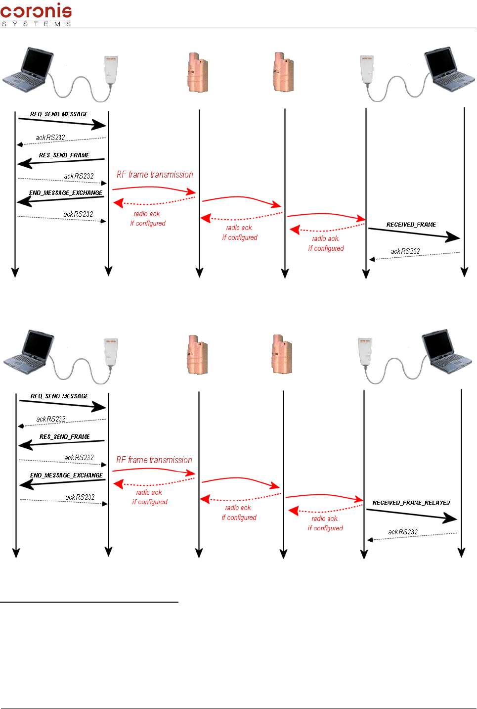
Document : XTLMOD -UserMan.sxw
With RELAY_ROUTE_STATUS parameter activated ( = 0x01 )
➢ Frame RECEPTION_ERROR format
With this command, the local WaveCard informs its host that a problem appeared at the time of the radio
exchange.
This command is forwarded only on the serial link, between the wavecard and its host, it thus does not
require an address of recipient.
XLTMOD Handbook page 50 of 74

Document : XTLMOD -UserMan.sxw
Note: The error messages are activated only if parameter EXCHANGE_STATUS is positioned with
0x01, or 0x03.
In 'Point-to-Point' mode
RECEPTION_ERROR
HEADER CMD DATA CRC ETX
3 bytes 1 byte 1 byte 1 byte 2 bytes 1 byte
0xFF ; 0x02 ;
0x06 0x31
EXCHANGE_MODE :
= 0x01 : Point-to-Point
mode
ERROR_TYPE :
= 0x01 : Distant equipment RF
acknowledge not received
(useful if acknowledge
mechanism is set)
= 0x02 : Distant equipment RF
response not received.
0x03
In 'relaying' mode
RECEPTION_ERROR
HEADER CMD DATA CRC ETX
3 bytes 1 byte 1 byte 1 byte 1 byte 2 bytes 1 byte
0xFF ;
0x02 ;
0x06
0x31
EXCHANGE_MODE
:
= 0x02 : relaying
mode
0x02
Default value
for relaying
mode
RELAY_COUNTER :
= 0x03 No response from the third
repeater;
= 0x02 No response from the second
repeater;
= 0x01 No response from the first
repeater;
= 0x00 No response from the final
equipment.
0x03
Note: In the MESSAGE mode, the error frame intervene only between the transmitter, and the first
repeater. Even if the other repeaters return errors, the transmitting module does not await an answer, and
proceeds to another action.
In both cases, the procedure of sending an error frame depends on parameter RADIO_ACKNOWLEDGE:
If RADIO_ACKNOWLEDGE is active, and the transmitter does not receive a radio
acknowledgement, then the request is re-emitted three times, before sending the error frame.
If RADIO_ACKNOWLEDGE is inactive, then the error frame is sent after time-out
RADIO_USER_TIMEOUT.
XLTMOD Handbook page 51 of 74

Document : XTLMOD -UserMan.sxw
XLTMOD Handbook page 52 of 74

Document : XTLMOD -UserMan.sxw
5.3- ’Polling’ Mode
This mode allows to address a request to a list of predefined distant equipment. The response is sent to the
host, transmitter of the request, when all the distant equipments responded; or on timeout. Two types of
exchanges in polling mode can be distinguished,
Not-selective Polling : all the distant equipments, configured in POLLING_ROUTE table, are
interrogated.
Selective Polling : only a given group of distant equipments, configured in POLLING_ROUTE
table, are interrogated.
5.3.1 - Configuration of the parameters relating to the 'Polling' mode
The parameters are accessible by commands REQ_READ_RADIO_PARAM, and REQ_WRITE_RADIO_PARAM
(all the parameters are developed in appendix 3).
NUM DESCRIPTION VALUE SIZE
(in bytes)
0x03
WAVECARD_POLLING_GROUP : Byte
containing the Polling Group of the
Wavecard.
Byte 1 : Polling_Group
by default, Polling_Group = 0x00 1
0x08
POLLING_ROUTE : Table containing the
list of modules radio address to be
addressed.
Byte 2 : number of equipments to
interrogate
IF Byte 2 != 0
Bytes 3 to 8 : radio address of the
first module..., and so on.
1 à 241
0x09
GROUP_NUMBER : Byte containing the
number of the group of radio equipment
to address in radio polling mode.
Group number
by default, GROUP_NUMBER = 0x00 1
0x0A POLLING_TIME : delay between two
consecutive emission in polling mode
Value in multiples of 100ms
By default, POLLING_TIME = 0x0A 1
Example of parameter setting: Writing of the list of the distant equipments, addressed by the
polling mode.
In our example, we have two distant pieces of equipment, whose addresses (on 6 bytes) are
0xAAAAAAAAAAAA; and 0xBBBBBBBBBBBB.
We launch a REQ_WRITE_RADIO_PARAM request, by positioning byte CMD with 0x40. Then, in the
DATA field, we specify the number of the parameter to be modified, and its corresponding data,
according to the following format.
DATA field
1 byte variable
Number of the parameter to
modify Parameter data
Thus,
REQ_WRITE_RADIO_PARAM
Header CMD DATA CRC ETX
3 bytes 1 byte 1 byte variable 2 bytes 1 byte
XLTMOD Handbook page 53 of 74

Document : XTLMOD -UserMan.sxw
0xFF ; 0x02 ; 0x11 0x40 0x08
0x02
0xAAAAAAAAAAAA;
0xBBBBBBBBBBBB
0xXXXX 0x03
5.3.2 - Description of the commands, and their formats
CMD NAME DESCRIPTION
0x21 RES_SEND_FRAME
Response from the radio board to the frame emission
(response to the request 0x20, 0x22, 0x24, 0x26, 0x28,
0x2A)
0x26 REQ_SEND_POLLING Request to send a radio frame with the polling mode.
0x32 RECEIVED_FRAME_POLLING Received radio frame following a REQ_SEND_POLLING
request
The format of the types of frame received by the host, are described as follow.
➢Request in 'Polling' mode
REQ_SEND_FRAME
HEADER CMD DATA CRC ETX
3 bytes 1 byte variable 2 bytes 1 byte
0xFF ; 0x02 ;
0xXX 0x26 n bytes of data to transmit
the maximum size is 152 bytes 0x03
Remark : in radio polling mode, it is not necessary to transmit the address of the modules to be
interrogated, since they must be configured by the intermediary of the parameter POLLING_ROUTE.
➢Acknowledgement of the request
RES_SEND_FRAME
HEADER CMD DATA CRC ETX
3 bytes 1 byte 1 byte 2 bytes 1 byte
0xFF ; 0x02 ;
0x05 0x21
Status
0x00 : transmission OK
0x01 : transmission error
0x03
➢Réponse à la requête de type 'Polling'
RECEIVED_FRAME_POLLING
HEADER CMD DATA CRC ETX
3 bytes 1 byte 1 byte 6 bytes variable 2 bytes 1 byte
XLTMOD Handbook page 54 of 74
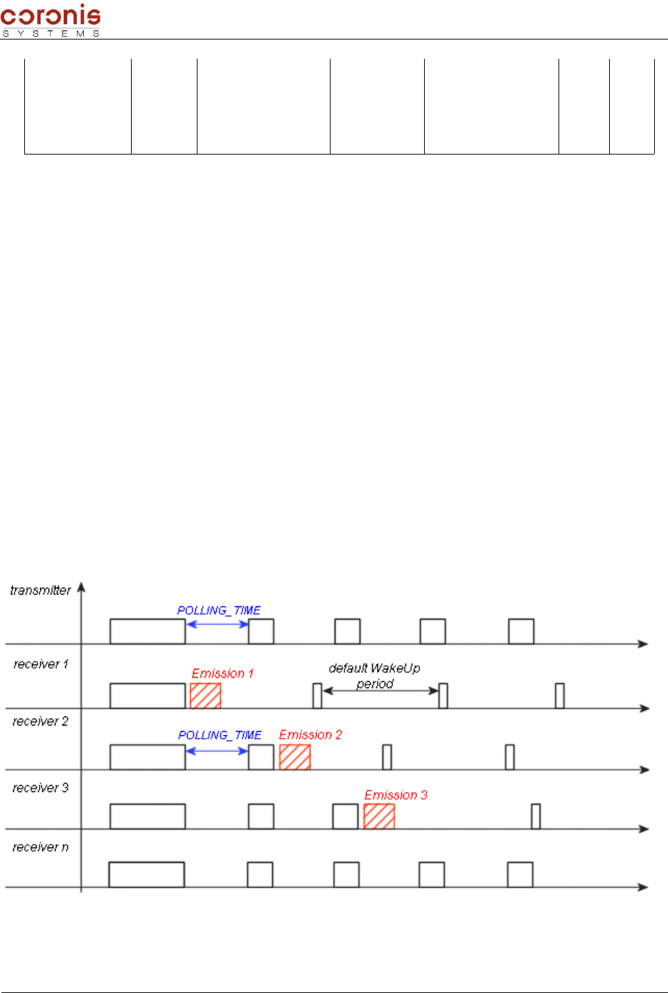
Document : XTLMOD -UserMan.sxw
0xFF ; 0x02 ;
0xXX 0x32
STATUT_RECEPTION :
= 0 : response OK
= 1 : no response from
the interrogated
equipment
Radio address
of the
interrogated
equipment
data from received
frame
the maximum size is
152 bytes
0x03
5.3.3 - Difference between selective, and not-selective Polling mode
Generally, the use of the polling mode (selective, or not-selective) requires the configuration of a table
containing the addresses of the modules to be interrogated (POLLING_ROUTE).
When using the selective polling mode, it is necessary to configure on the transmitter side, the group number
of modules to be interrogated.
In this way, when sending a request in selective polling mode, only the modules included in the table, with the
same group number as configured in the transmitter, will be interrogated.
Contrary to the not-selective polling mode, where all the modules included in the list will be interrogated.
➢Principle of the not-selective 'polling' mode
When using a not-selective polling, all the modules within radio range are synchronized on the transmitter
(short WakeUp, every POLLING_TIME), but only the interrogated modules respond.
After sending the response, the interrogated modules are re-initialized with their default Wake-Up
period.
The not-interrogated modules are re-initialized with their default WakeUp period, when the
transmitter stops its interrogation in Polling mode.
The procedure to initiate a request in not-selective polling mode, is as follows:
XLTMOD Handbook page 55 of 74
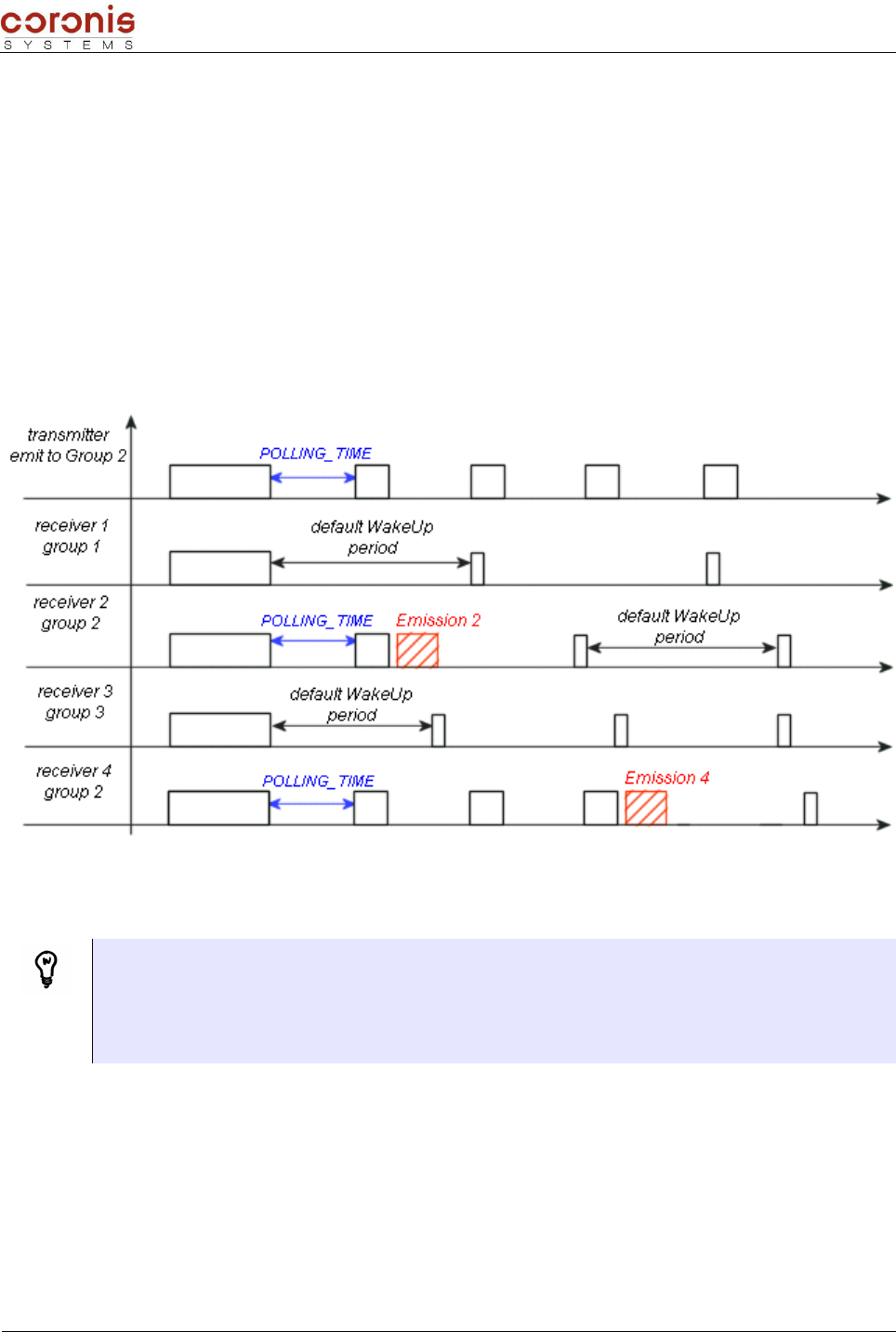
Document : XTLMOD -UserMan.sxw
Configure POLLING_ROUTE table, with all the addresses of modules to be interrogated
Launch a request of internal parameter modification
Launch a request in 'Polling' mode
➢Principle of the selective Polling mode
Only the modules which belong to the interrogated group are synchronized on the transmitter. A module will
respond to a selective polling request only on the following conditions :
it belongs to the interrogated group,
its radio address is contained in the list of the interrogated modules (POLLING_ROUTE).
Synchronization allows a faster response of the modules (Since it don't use Long WakeUp) and optimize
consumption.
Attention, when interrogating a WaveTherm module in Polling mode, the reading time of a temperature
can be much longer than the default POLLING_TIME value. In this case, this parameter shall be increased
consequently.
- DALLAS Probe: reading in 800ms by probe
- Probe PT100, PT1000: the reading time depends on the index of precision. (max. 3 seconds)
The procedure to be followed, to initiate a request in selective polling mode, is :
To configure table POLLING_ROUTE, with all the addresses of modules to be interrogated ;
by transmitting a request of modification of internal parameter
To configure the group number of each distant equipments contained in the table
(POLLING_ROUTE) ;
by transmitting a request of modification of internal parameter
To choose the group to interrogate, and transmit the polling request.
XLTMOD Handbook page 56 of 74

Document : XTLMOD -UserMan.sxw
When a WaveCard (or WavePort) is the receiver of a selective Polling request, the user must specify to
which group WaveCard belongs. For that, it is necessary to configure parameter
WAVECARD_POLLING_GROUP, with the number of selected group.
Attention not to confuse this parameter with the parameter GROUP_NUMBER which gives the number of
group to be reached, when WaveCard is transmitting a selective Polling request.
Example of a selective polling exchange :
WaveCard is configured like described below,
POLLING_ROUTE GROUP_NUMBER
Equipment A address 0x01
Equipment B address
Equipment C address
Equipment D address
Equipment E address
After transmitting the REQ_SEND_POLLING request, the distant equipments react in the following way:
•
Equipment A : responds to the request. PARTICULAR CASE, this module is the
first of table POLLING_ROUTE, and the first polling frame is sent in point-to-point mode;
•
Equipment B : responds to the request (belongs to the interrogated group)
•
Equipment C : responds to the request (belongs to the interrogated group)
•
Equipment D : responds to the request (belongs to the interrogated group)
•
Equipment E : no response (doesn't belong to the interrogated group).
XLTMOD Handbook page 57 of 74
Host WaveCard
A
Grp 2
B
Grp 1
C
Grp 1
D
Grp 1
E
Grp 2
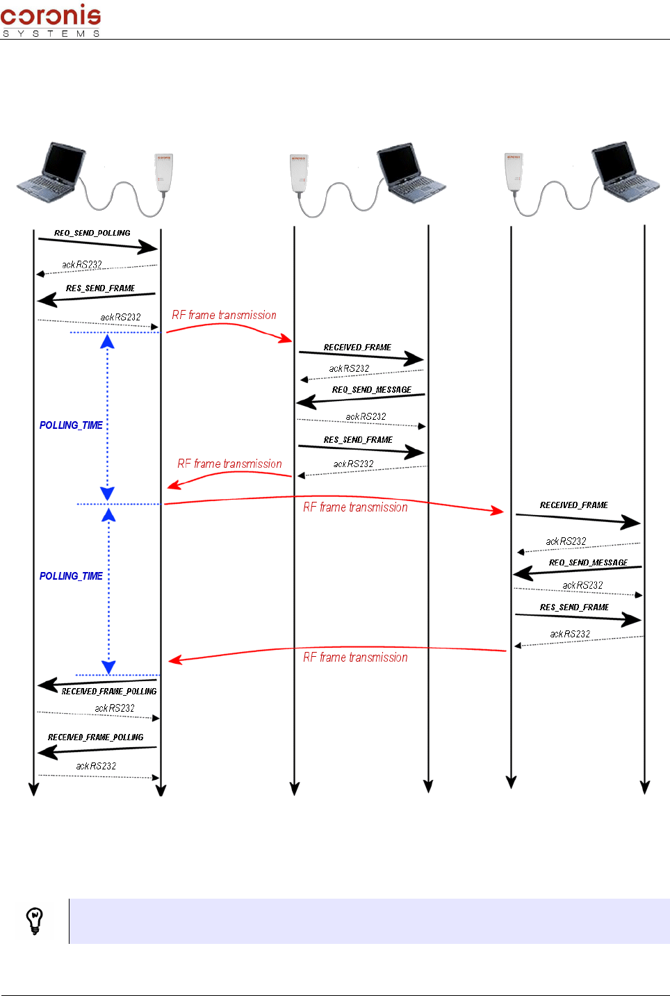
Document : XTLMOD -UserMan.sxw
5.3.4 - Diagram of an exchange in polling mode
the following example describes the typical case where the distant WaveCards communicate with their
respective host. Indeed, when sending a GET_TYPE request (see chapter XXX) in polling mode; distant
WaveCards respond without preliminary dialogue with their host.
POLLING_TIME : after transmitting the radio frame, a timeout is started (configured by POLLING_TIME
parameter); and if the equipment doesn't respond before the end of the timeout (1 second by default), then
the transmitter send the same radio frame to the next distant equipment. However, if the previous distant
equipment responded after this timeout; its response frame would be lost.
Parameter POLLING_TIME can be modified via the commands of parameter setting.
Remark: even if the distant equipment responds before the POLLING_TIME timeout, the next request is
sent only after the timeout, for synchronization considerations.
XLTMOD Handbook page 58 of 74
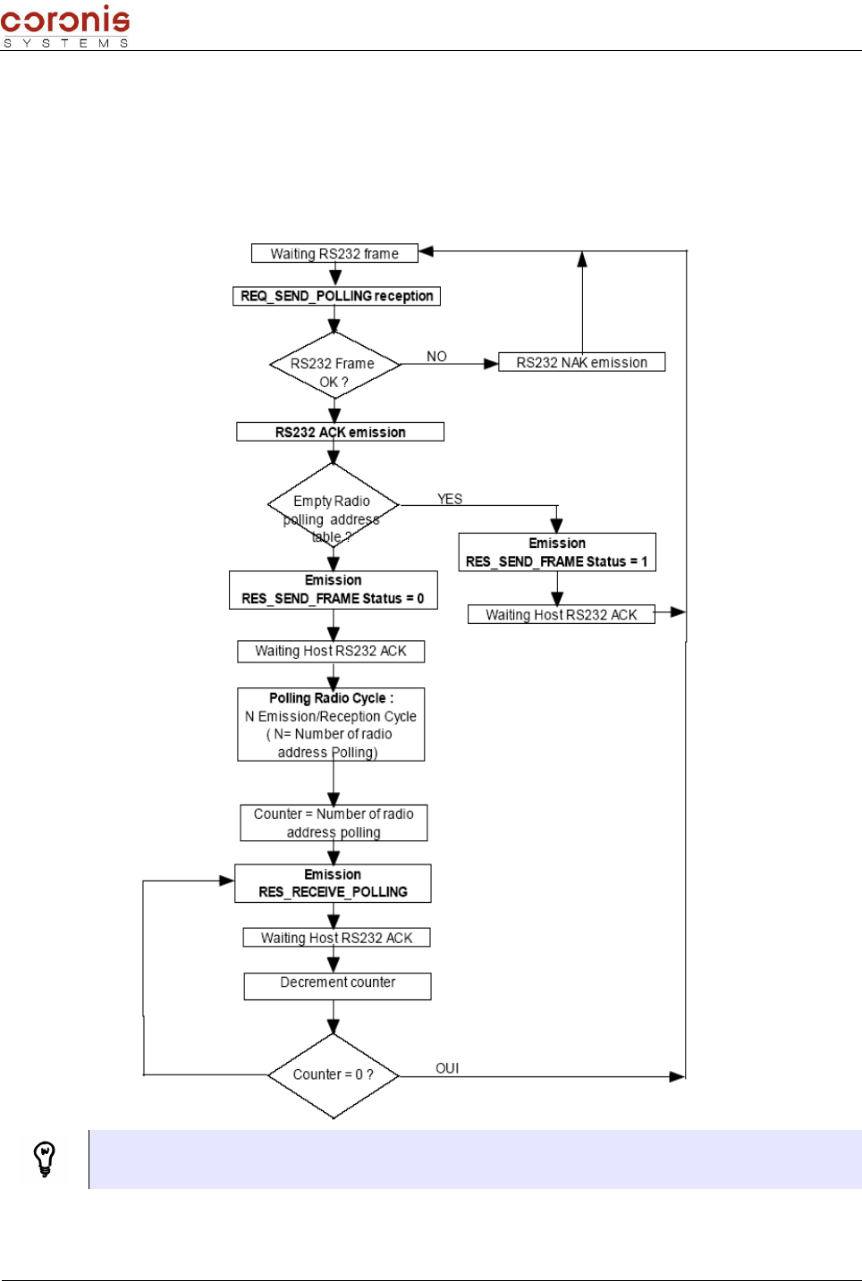
Document : XTLMOD -UserMan.sxw
The low level commands are necessary to recover the RECEIVED_FRAME_POLLING responses.
Indeed, an index is incremented with each reception of a polling response. And when the WaveCard,
instigator of the polling exchange does not await new responses anymore, it sends to its host a first
RECEIVED_FRAME_POLLING command ;and will await a low level acknowledgement to decrease its index,
and to send next RECEIVED_FRAME_POLLING command.
The following diagram describes the operations carried out by the WaveCard following the reception of a
REQ_SEND_POLLING command:
Remark : Whatever values configured in the RADIO_ACKNOWLEDGE parameter, it is not used
during an exchange in polling mode.
XLTMOD Handbook page 59 of 74

Document : XTLMOD -UserMan.sxw
5.4- ’Broadcast’ mode
This mode allows to address a request to all the equipments in radio range of the transmitter. Thus, it is not
necessary to specify the address of the distant equipment to reach.
Depending on the command used, the request can be sent with, or without awaiting for a response
( REQ_SEND_BROADCAST, or REQ_SEND_BROADCAST_MESSAGE commands).
In all cases, two types of exchanges in broacast mode can be distinguished,
Not-selective Broadcast : all the distant equipments in radio range of the transmitter, are
interrogated.
Selective Broadcast : only a given group of distant equipments in radio range of the transmitter,
are interrogated.
5.4.1 - Configuration of the parameters relating to the 'Broadcast' mode
The parameters are accessible by commands REQ_READ_RADIO_PARAM, and REQ_WRITE_RADIO_PARAM
(all the parameters are developed in appendix 3).
NUM DESCRIPTION VALUE
SIZE
(in
bytes)
0x0E
EXCHANGE_STATUS : parameter
relative to the error or status frame
management activation (see chapter ,
, et 5.4).
0 : status and error frame deactivated,
1 : error frame activated,
2 : status frame activated,
3 : both status and error frames activated,
by default, RECEPT_ERROR_STATUS = 0x00.
1
0x17
BCST_RECEPTION_TIMEOUT : timeout
used for the reception of CSMA frame
consecutively to
REQ_SEND_BROADCAST Command
emission (available from firmware
V2.01 version )
Valeur in multiples of100ms.
Default = 0x3C (6 seconds) 1
5.4.2 - 'BroadCast' mode without waiting for a response
This mode allows to address a request to all the equipments in radio range of the transmitter, without waiting
for a response. Depending to the setting of the EXCHANGE_STATUS parameter, the Wavecard will be
available for next RS232 serial link exchange :
After transmitting the broadcast request,
On reception of the END_MESSAGE_EXCHANGE command.
a) Description of the commands
CMD NAME DESCRIPTION
0x21 RES_SEND_FRAME Response from the radio board to the frame emission
(response to the request 0x20, 0x22,0x24, 0x26, 0x28,
0x2A )
0x2A REQ_SEND_BROADCAST_MESSAGE Request to send a radio frame in broadcast mode without
waiting for radio response.
0x37 END_MESSAGE_EXCHANGE
Frame indicating end of message exchange.This frame is
returned only after 0x22 & 0x24 & 0x2A Request command.
Reception of this frame is conditioned by the parameter
EXCHANGE_STATUS value.
XLTMOD Handbook page 60 of 74

Document : XTLMOD -UserMan.sxw
0x38 RECEIVED_BROADCAST_FRAME Received a radio frame transmitted in a broadcast mode
b) Example of operations during a broadcast exchange, without waiting for responses
Reception of the END_MESSAGE_EXCHANGE command depends on the activation of the
EXCHANGE_STATUS parameter (0x0E). This command allows the equipment host to know exactly the
moment from which WaveCard is available for communication RS232.
5.4.3 - 'BroadCast' mode with waiting for responses
After transmitting a broadcast request, the WaveCard begins a reception phase during which it will memorize
all the responses. This phase stops on a timeout configured by BCST_RECEPTION_TIMEOUT parameter
(0x17). With each reception of response frame, the timeout is re-initialized.
After timeout, the WaveCard send the responses towards its host, via the serial link connection, frame after
frame.
a) Description of the commands
CMD NAME DESCRIPTION
0x21 RES_SEND_FRAME Response from the radio board to the frame emission (response
to the request 0x20, 0x22,0x24, 0x26, 0x28, 0x2A )
0x24 REQ_SEND_BROADCAST_RESPONSE Request to send a radio frame in response to a broadcast frame
0x28 REQ_SEND_BROADCAST Request to send a radio frame in broadcast mode.
0x34 RECEIVED_BROADCAST_RESPONSE Received radio frame following a REQ_SEND_BROADCAST request
0x37 END_MESSAGE_EXCHANGE
Frame indicating end of message exchange.This frame is returned only
after 0x22 & 0x24 & 0x2A Request command. Reception of this frame
is conditioned by the parameter EXCHANGE_STATUS value.
XLTMOD Handbook page 61 of 74
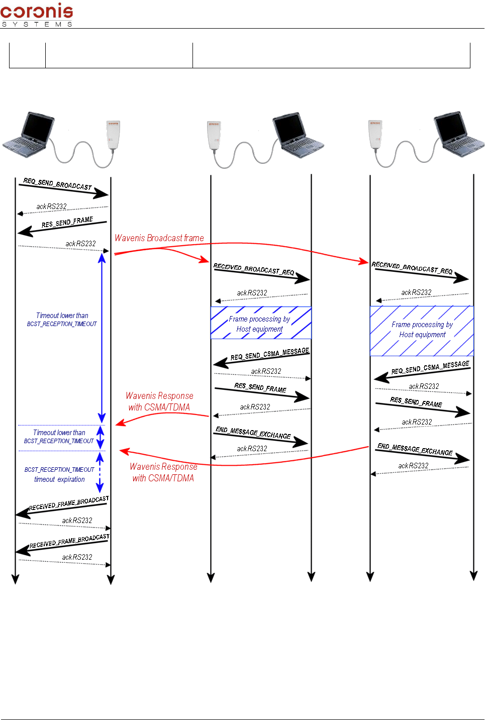
Document : XTLMOD -UserMan.sxw
0x38 RECEIVED_BROADCAST_FRAME Received a radio frame transmitted in a broadcast mode
b) Example of operations during a broadcast exchange, with waiting for responses
Reception of the END_MESSAGE_EXCHANGE command depends on the activation of the
EXCHANGE_STATUS parameter (0x0E). This command allows the equipment host to know exactly the
moment from which WaveCard is available for communication RS232.
XLTMOD Handbook page 62 of 74

Document : XTLMOD -UserMan.sxw
5.4.4 - Format of the commands – from the request transmitter side
➢Broadcast requests – 0x28 ou 0x2A (REQ_SEND_BROADCAST or
REQ_SEND_BROADCAST_MESSAGE)
REQ_SEND_BROADCAST ou REQ_SEND_BROADCAST_MESSAGE
HEADER CMD DATA CRC ETX
3 bytes 1 byte 6 bytes variable 2 bytes 1 byte
0xFF ; 0x02 ;
0xXX 0x28 Group number to interrogate
in broadcast mode
n bytes of data to transmit
the maximum size is 152
bytes
0x03
Group number to interrogate : Only the most significant byte (MSByte) really corresponds to the
number of group, the 5 other bytes are not significant.
Remark : if the number of group is 0xFF 0xXX 0xXX 0xXX 0xXX 0xXX, all the modules receiving the
broadcast frame are authorized to transmit a response.
➢Acknowledgement of the request – 0x21 (RES_SEND_FRAME)
RES_SEND_FRAME
HEADER CMD DATA CRC ETX
3 bytes 1 byte 1 byte 2 bytes 1 byte
0xFF ; 0x02 ;
0x05 0x21
Status
0x00 : transmission OK
0x01 : transmission error
0x03
➢Response to the broadcast request – 0x34 (RECEIVED_BROADCAST_RESPONSE)
RECEIVED_BROADCAST_RESPONSE
HEADER CMD DATA CRC ETX
3 bytes 1 byte 1 byte 1 byte 1 byte 6 bytes variable 2 bytes 1 byte
0xFF ; 0x02 ;
0xXX 0x34 Status
Total
number of
frames
received
Frames
Index
Radio address
of the
transmitter of
the response
Received
data
152 bytes
max.
0x03
Status : = 0 : reception Ok
= 1 : indicate that the number of received responses is higher than 255. in this case,
only the first 255 responses will be sent to the host.
Frames index : This index is used by the wavecard to know how many responses must be sent
to the host. this index is decreased on low level acknowledgement, when the wavecard send a
response to its host.
The host knows that all the responses was sent to him, when the frames index indicates 1.
XLTMOD Handbook page 63 of 74
Document : XTLMOD -UserMan.sxw
This index is also used to check that no frame was lost by ensuring that this value is well
decreased with each received frame.
5.4.5 - Format of the commands – from the request receiver side
➢Reception of a broadcast request – 0x38 (RECEIVED_BROADCAST_FRAME)
RECEIVED_BROADCAST_FRAME
HEADER CMD DATA CRC ETX
3 bytes 1 byte 6 bytes variable 2 bytes 1 byte
0xFF ; 0x02 ;
0xXX 0x38 Radio address of the
transmitter of the request
n bytes of data
the maximum size is 152
bytes
0x03
➢Transmission of the response to a broadcast request – 0x24
(REQ_SEND_BROADCAST_RESPONSE)
REQ_SEND_BROADCAST_RESPONSE
HEADER CMD DATA CRC ETX
3 bytes 1 byte 6 bytes variable 2 bytes 1 byte
0xFF ; 0x02 ;
0xXX 0x24 Radio address of the
transmitter of the request
n bytes of data to transmit
the maximum size is 152
bytes
0x03
Remark : This command can only be used after the reception of a broadcast frame
(RECEIVED_BROADCAST_FRAME = 0x38). So, destination radio address of this message could
only be this from the emitter of the Broadcast frame.
Use of this command in any other circumpstances could make the Wavecard not available during a
few seconds.
➢Status Message – 0x37 (END_MESSAGE_EXCHANGE)
END_MESSAGE_EXCHANGE
HEADER CMD DATA CRC ETX
3 bytes 1 byte 1 byte 2 bytes 1 byte
0xFF ; 0x02 ;
0xXX 0x37 0x00 0x03
Attention, use of this command depends on the activation of status message, in parameter
EXCHANGE_STATUS (0x0E).
5.4.6 - Use of the selective, or not-selective broadcast mode
To initiate a Broadcast request, either in selective or not-selective mode, there is no particular procedure. The
XLTMOD Handbook page 64 of 74

Document : XTLMOD -UserMan.sxw
user just has to ensure that the distant modules have their GROUP_NUMBER parameter configured.
Then, the user has to send a broadcast request (with, or without waiting for responses), by configuring 'group
number' to adjust selectivity.
Group number = 0xFF 0xXX 0xXX 0xXX 0xXX 0xXX not-selective mode
Group number = 0x01 0xXX 0xXX 0xXX 0xXX 0xXX selective mode
In this last case, all the equipments within radio range, having their group number configured with 0x01, will
receive the broadcast command.
XLTMOD Handbook page 65 of 74

Document : XTLMOD -UserMan.sxw
5.5- ’Multi frames' Mode
Multi frame mode allows multi frame exchange between the Wavecard/Waveport (considered like the master
of the exchange) and one of the telemetry equipments of the Coronis Systems product family ( WaveTherm,
WaveFlow, WaveSens, ...).
Le mode multitrames a été developpé pour permettre le dialogue entre une WaveCard/ WavePort et un
module CORONIS de télémétrie. Il n'est accessible dans la version du firmware actuelle, qu'aux utilisateurs
pilotant un réseau de modules de télémétrie CORONIS, depuis une WaveCard/ WavePort.
Restrictions relative to the use of multi frame mode: Current version of Wavecard does not allow multi
frame mode between two Wavecard/Waveport equipments.
In addition, the firmware version does not allow multi frame mode usage through repeaters.
5.5.1 - Principle
Wavecard equipment is able to manage reception of successive frames coming from an distant equipment.
Data are first stored in internal memory and restored to host equipment with serial link when RF reception is
ended.
The multi frame mechanism is initiate by distant equipment , depending on the quantity of data to transmit,
following a point to point request from Wavecard.
5.5.2 - Format of the received frames
➢Reception of a 'multi frame' – 0x36
RECEIVED_MULTIFRAME
HEADER CMD DATA CRC ETX
3 bytes 1 byte 1 byte 1 byte 1 byte 6 bytes variable 2 bytes 1 byte
0xFF ; 0x02 ;
0xXX 0x36 Status
Total
number of
received
frames
Frames
index
Radio address
of the
transmitter of
the response
Received
data
152 bytes
max.
0x03
Status : = 0 : reception Ok
= 1 : indicate that the number of received responses is higher than 255. in this case,
only the first 255 responses will be sent to the host.
Frames index : This index is used by the wavecard to know how many responses must be sent
to the host. this index is decreased on low level acknowledgement, when the wavecard send a
response to its host.
The host knows that all the responses was sent to him, when the frames index indicates 1.
This index is also used to check that no frame was lost by ensuring that this value is well
decreased with each received frame.
XLTMOD Handbook page 66 of 74
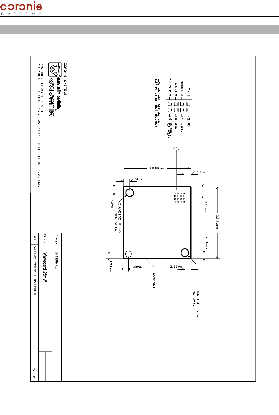
Document : XTLMOD -UserMan.sxw
APPENDIX 1 : Mechanical description of the WAVECARD
➢WaveCard - 25mW
XLTMOD Handbook page 67 of 74
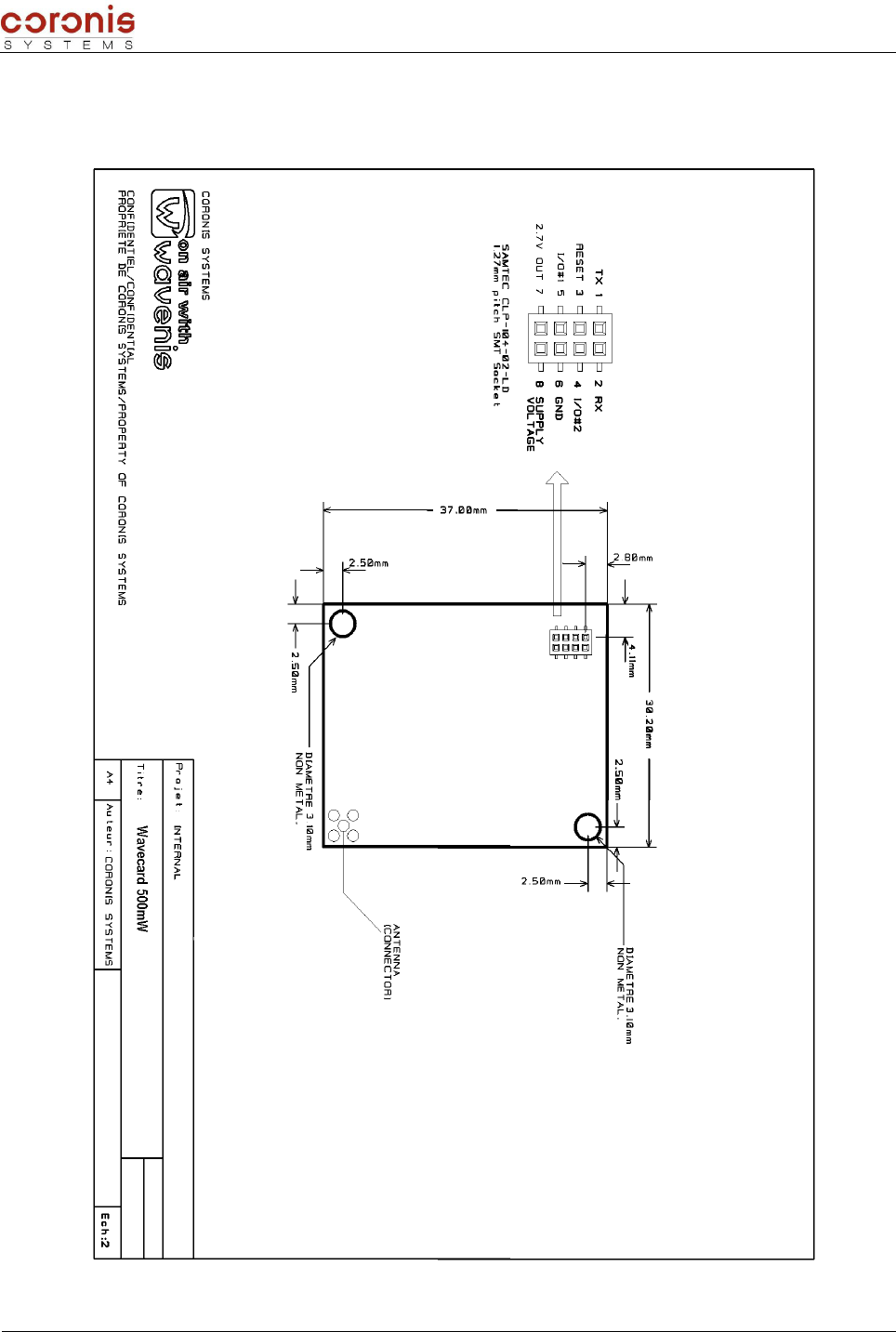
Document : XTLMOD -UserMan.sxw
➢WaveCard - 500mW
XLTMOD Handbook page 68 of 74

Document : XTLMOD -UserMan.sxw
APPENDIX 2 : Electric interface of the WAVECARD
➢WaveCard - 25mW
PIN # PIN NAME DESCRIPTION INPUT / OUTPUT
1 TX TX RS232 signal OUTPUT
2 RX RX RS232 signal INPUT
3 RESET RESET input (active to high level) INPUT
4 OUT2 Not used OUTPUT
5 OUT1 output active (level 1) when reception is on OUTPUT
6 GND ground OUTPUT
7 +3V OUT 3V regulated output voltage (10mA available) OUTPUT
8SUPPLY
VOLTAGE
input supply voltage (4V to 5.5V)
minimum current 45mA INPUT
➢WaveCard - 500mW
PIN # PIN NAME DESCRIPTION INPUT / OUTPUT
1 TX TX RS232 signal (0 ;+2,7Vmax) OUTPUT
2 RX RX RS232 signal (0 ;+2,7Vmax) INPUT
3 RESET RESET input (active to high level) INPUT
4 OUT2 Not used OUTPUT
5 OUT1 output active (high level) when periodic reception is on OUTPUT
6 GND ground OUTPUT
7 +2,7V OUT 2,7V regulated output voltage (10mA available) OUTPUT
8SUPPLY
VOLTAGE
input supply voltage [3V à 4,3V]
• 700mA minimum current peak INPUT
XLTMOD Handbook page 69 of 74

Document : XTLMOD -UserMan.sxw
APPENDIX 3 : List of the functional parameters
Paramete
r number
Description Value Size
(bytes)
0x00 AWAKENING_PERIOD : polling period of RF medium
radio, in multiples of 100ms
Period in multiples of 100ms
(by default, 0x0A for one second)
0 = quasi-permanent reception (every
20ms)
1
0x01 WAKEUP_TYPE : Wake Up type used during a frame
emission
0 : long Wake Up (default setting)
1 : short Wake Up = 50 ms 1
0x02
WAKEUP_LENGTH : duration of the Wake up when
long wake up is set up.
This value must be higher than the polling period of
RF medium radio. Value in multiples of 1ms, defined
LSB first
Default value : 1100 ms
min value = 20 ms (0x1400)
max value = 10 sec. (0x1027)
2
0x03 WAVECARD_POLLING_GROUP : Byte containing the
Polling Group of the Wavecard.
Byte 1 : Polling_Group
by default, Polling_Group = 0x00 1
0x04 RADIO_ACKNOWLEDGE : indicates if the radio
frames must be acknowledged by the receiver.
0 : no acknowledge (default value)
1 : acknowledge used 1
0x05 RADIO_ADDRESS : radio board address
This Value is issue from the
manufacturing.
In Reading only
6
0x06
RELAY_ROUTE_STATUS : Parameter relative to
Relay route transmission in each relayed frame
received.
0x00 : Relay route transmisson deactivated
0x01 : Relay route transmission activated
by default, Relay route transmisson
deactivated
1
0x07
RELAY_ROUTE : Table containing the radio
addresses for successive repeaters to use to reach
the final equipment.
BYTE 1 : number of repeaters in the route
Maximum repeater number = 3
If BYTE 1 != 0
BYTES 2 à 7 : First repeater radio
address
…, and so on.
1 à 19
0x08 POLLING_ROUTE : Table containing the list of
modules radio address to be addressed.
BYTE 2 : number of equipments to
interrogate
IF BYTE 2 != 0
BYTES 3 to 8 : radio address of the first
module..., and so on.
1 à 241
0x09
GROUP_NUMBER : Byte containing the number of
the group of radio equipment to address in radio
polling mode.
Group number
by default, GROUP_NUMBER = 0x00 1
0x0A POLLING_TIME : delay between two consecutive
emission in polling mode
Value in multiples of 100ms
By default, POLLING_TIME = 0x0A 1
0x0C RADIO_USER_TIMEOUT : time-out used for the
reception of a response frame
Value in multiples of 100ms
default value = 0x14 (2 seconds) 1
XLTMOD Handbook page 70 of 74

Document : XTLMOD -UserMan.sxw
0x0E EXCHANGE_STATUS : parameter relative to the
error or status frame management activation.
0 : status and error frame deactivated,
1 : error frame activated,
2 : status frame activated,
3 : both status and error frames activated,
by default, RECEPT_ERROR_STATUS =
0x00.
1
0x10
SWITCH_MODE_STATUS : automatic selection of
Radio physical mode used to address an equipment
depending on radio address
0 : automatic selection deactivated
1 : automatic selection activated
Default value, SWITCH_MODE_STATUS =
0x00
1
0x16
WAVECARD_MULTICAST_GROUP : Byte containing
the Multicast Group of the Wavecard (available from
V2.00 version ).
By default, no group selected = 0xFF 1
0x17
BCST_RECEPTION_TIMEOUT : timeout used for the
reception of CSMA frame consecutively to
REQ_SEND_BROADCAST Command emission
(available from firmware V2.01 version )
Valeur in multiples of100ms.
Default = 0x3C (6 seconds) 1
APPENDIX 4 : List of the commands of parameters setting
CMD Name Description
0x40 REQ_WRITE_RADIO_PARAM Request to update the radio parameters
0x41 RES_WRITE_RADIO_PARAM Response from the radio board to the radio parameters update
0x42 REQ_CHANGE_UART_BDRATE Request to update serial link Baudrate
0x43 RES_CHANGE_UART_BAUDRATE Response from the radio board to the serial link baudrate update. Serial Link
Baudrate is updated once the exchange is ended
0x44 REQ_CHANGE_TX_POWER(1) Request to update radio board emission power
0x45 RES_CHANGE_TX_POWER(1) Response from the radio board to the emission power update
0x46 REQ_WRITE_AUTOCORR_STATE Request to update WAVENIS RF ASIC RSSI Threshold autocorrection
state
0x47 RES_WRITE_AUTOCORR_STATE Response from the radio board to the WAVENIS RF ASIC
autocorrection state update
0x50 REQ_READ_RADIO_PARAM Request to read the radio parameters.
0x51 RES_READ_RADIO_PARAM Response from the radio board to a parameters reading.
0x54 REQ_READ_TX_POWER Request to read radio board emission power
0x55 RES_READ_TX_POWER Response from the radio board to the emission power reading
0x5A REQ_READ_AUTOCORR_STATE Request to read WAVENIS RF ASIC RSSI Threshold autocorrection
state
0x5B RES_READ_AUTOCORR_STATE Response from the radio board to the WAVENIS RF ASIC
autocorrection state reading.
0x60 REQ_SELECT_CHANNEL Request to select the radio operating channel when FHSS is deselected
0x61 RES_SELECT_CHANNEL Response to the channel selection request
0x62 REQ_READ_CHANNEL Request to read the radio operating channel when FHSS is deselected
0x63 RES_READ_CHANNEL Response to the read channel request
0x64 REQ_SELECT_PHYCONFIG Request to select the RF medium physical mode
0x65 RES_SELECT_PHYCONFIG Response to the physical mode selection request
XLTMOD Handbook page 71 of 74

Document : XTLMOD -UserMan.sxw
CMD Name Description
0x66 REQ_READ_PHYCONFIG Request to read the RF medium physical mode
0x67 RES_READ_PHYCONFIG Response to the physical mode reading request
0x68 REQ_READ_REMOTE_RSSI request to read RSSI level from remote equipment
0x69 RES_READ_REMOTE_RSSI Response to the read remote RSSI level request
0x6A REQ_READ_LOCAL_RSSI Request to read the Wavecard RSSI level on an exchange with a distant
equipment
0x6B RES_READ_LOCAL_RSSI Response to the read local RSSI level request
0xA0 REQ_FIRMWARE_VERSION Request to read the radio board firmware version.
0xA1 RES_FIRMWARE_VERSION Response from the radio board to the firmware version reading.
0xB0 MODE_TEST Put the Wavecard in a selected test mode
(1) : These commands are accessible only on 25mW Wavecard radio board.
XLTMOD Handbook page 72 of 74

Document : XTLMOD -UserMan.sxw
APPENDICE 5 : List of the commands of data transmission
CMD NAME DESCRIPTION
0x20 REQ_SEND_FRAME Request to send a radio frame with the waiting for the radio
response.
0x21 RES_SEND_FRAME Response from the radio board to the frame emission (response to
the request 0x20, 0x22,0x24, 0x26, 0x28, 0x2A )
0x22 REQ_SEND_MESSAGE Request to send a radio frame without the waiting for the radio response.
0x24 REQ_SEND_BROADCAST_RESPONS
ERequest to send a radio frame in response to a broadcast frame
0x26 REQ_SEND_POLLING Request to send a radio frame with the polling mode.
0x28 REQ_SEND_BROADCAST Request to send a radio frame in broadcast mode.
0x2A REQ_SEND_BROADCAST_MESSAGE Request to send a radio frame in broadcast mode without waiting for radio
response.
0x30 RECEIVED_FRAME Received radio frame by the radio board.
0x31 RECEPTION_ERROR Frame indicating error type detected at the issue of last exchange in point to
point or relaying mode.
0x32 RECEIVED_FRAME_POLLING Received radio frame following a REQ_SEND_POLLING request
0x34 RECEIVED_BROADCAST_RESPONSE Received radio frame following a REQ_SEND_BROADCAST request
0x35 RECEIVED_FRAME_RELAYED Received relayed radio frame by the radio board .Reception of this command
is possible only if RELAY_ROUTE_STATUS(0x06) parameter is set.
0x36 RECEIVED_MULTIFRAME Received radio frame in multi frame mode. Indicates that following frames
are pending.
0x37 END_MESSAGE_EXCHANGE
Frame indicating end of message exchange.This frame is returned only after
0x22 & 0x24 & 0x2A Request command. Reception of this frame is
conditioned by the parameter EXCHANGE_STATUS value.
0x38 RECEIVED_BROADCAST_FRAME Received a radio frame transmitted in a broadcast mode
XLTMOD Handbook page 73 of 74

Document : XTLMOD -UserMan.sxw
NOTE: This equipment has been tested and found to comply with the limits for a Class B digital device,
pursuant to Part 15 of the FCC Rules.
These limits are designed to provide reasonable protection against harmful interference in a residential
installation.
This equipment generates, uses, and can radiate radio frequency energy and, if not installed and used in
accordance with the instructions, may cause harmful interference to radio communications. However, there is
no guarantee that interference will not occur in a particular installation.
If this equipment does cause harmful interference to radio or television reception, which can be determined
by turning the equipment off and on, the user is encouraged to try to correct the interference by one or more
of the following measures:
- reorient or relocate the receiving antenna.
- increase the separation between the equipment and receiver.
- connect the equipment into an outlet on a circuit different from that to which the receiver is connected.
- consult the dealer or an experienced radio/TV technician for help.
XLTMOD Handbook page 74 of 74