ODF Optronics EBR1 Remote Video and Audio Device User Manual Eye Ball R1
ODF Optronics, Ltd. Remote Video and Audio Device Eye Ball R1
User Manual
EYE BALL R1
COMPACT WIRELESS
360° MOBILE DISPLAY SYSTEM
IMPORTANT!
READ ALL INSTRUCTIONS
IN THIS MANUAL BEFORE
USING THIS PRODUCT.
Page 2 .........Specifications
Page 3 .........About
Page 8 .........Charging
Page 10 .......Using
Page 21 .......Training
Page 22 .......Maintaining
OWNER’S MANUAL
Eye Ball FCC ID:TII-EBR1
This device complies with Part 15 of the FCC Rules. Operation is subject to the following two conditions: (1) this device may not cause harmful
interference, and (2) this device must accept any interference received, including interference that may cause undesired operation.
This device has been authorized by the Federal Communications Commission for sale only directly to law enforcement organizations that are
eligible for licensing under the provisions of Section 90.20 of the Commission’s rules. This device has not been authorized and may not be offered for
sale or lease, or sold or leased, to any other entities.
The Eyeball transmitters shall be used only by law enforcement agencies for emergencies involving safety-of -life and for training purposes. The
transmitters shall not be used for permanent or fixed operations . In order to comply with FCC radio frequency (RF) exposure limits, PDU antennas
should be held at a minimum of 7.9 inches (20 cm) or more from the body of all users. Please refer to page 11 of this manual.
This device operates at the 2.4 GHz band, a frequency band used by radio local area network equipment, cordless telephones, and other
unlicensed devices that are certified by the Federal Communications Commission (FCC). Such other devices operating in the same vicinity as the
Eyeball R1 could cause degradation or loss of its signal. Operation of this device could cause other 2.4 GHz devices and s ystems in the vicinity
to lose their ability to transmit packets or digital signals, or may slow packet transmission rates and their operation could interfere with this
device. Where repetitious use of the device is planned in a specific geographic area (e.g., a security perimeter), and when it will not compromise the
mission, frequency coordination with existing 2.4 GHz systems is desirable to minimize the potential for mutual interference. Where possible and not
mission compromising, Eye Ball R1 users should select a channel that is not in use by other 2.4 GHz devices in the vicinity, or should notify area 2.4
GHz users how to adjust frequencies if their systems experience degradation in packet delivery rates.
The Eye Ball R1 is developed and manufactured by ODF Optronics Ltd.

Eye Ball FCC ID:TII-EBR1
This device complies with Part 15 of the FCC Rules. Operation is subject to the following two conditions: (1) this device may not cause harmful
interference, and (2) this device must accept any interference received, including interference that may cause undesired operation.
This device has been authorized by the Federal Communications Commission for sale only directly to law enforcement organizations that are
eligible for licensing under the provisions of Section 90.20 of the Commission’s rules. This device has not been authorized and may not be offered for
sale or lease, or sold or leased, to any other entities.
The Eyeball transmitters shall be used only by law enforcement agencies for emergencies involving safety-of -life and for training purposes. The
transmitters shall not be used for permanent or fixed operations .
This device operates at the 2.4 GHz band, a frequency band used by radio local area network equipment, cordless telephones, and other
unlicensed devices that are certified by the Federal Communications Commission (FCC). Such other devices operating in the same vicinity as the
Eyeball R1 could cause degradation or loss of its signal. Operation of this device could cause other 2.4 GHz devices and s ystems in the vicinity
to lose their ability to transmit packets or digital signals, or may slow packet transmission rates and their operation could interfere with this
device. Where repetitious use of the device is planned in a specific geographic area (e.g., a security perimeter), and when it will not compromise the
mission, frequency coordination with existing 2.4 GHz systems is desirable to minimize the potential for mutual interference. Where possible and not
mission compromising, Eye Ball R1 users should select a channel that is not in use by other 2.4 GHz devices in the vicinity, or should notify area 2.4
GHz users how to adjust frequencies if their systems experience degradation in packet delivery rates.
The Eye Ball R1 is developed and manufactured by ODF Optronics Ltd.
Eye Ball FCC ID:TII EBR1
This device complies with Part 15 of the FCC Rules. Operation is subject to the following two conditions: (1) this device may not cause harmful
interference, and (2) this device must accept any interference received, including interference that may cause undesired operation.
This device has been authorized by the Federal Communications Commission for sale only directly to law enforcement organizations that are
eligible for licensing under the provisions of Section 90.20 of the Commission’s rules. This device has not been authorized and may not be offered for
sale or lease, or sold or leased, to any other entities.
The Eyeball transmitters shall be used only by law enforcement agencies for emergencies involving safety-of -life and for training purposes. The
transmitters shall not be used for permanent or fixed operations .
This device operates at the 2.4 GHz band, a frequency band used by radio local area network equipment, cordless telephones, and other
unlicensed devices that are certified by the Federal Communications Commission (FCC). Such other devices operating in the same vicinity as the
Eyeball R1 could cause degradation or loss of its signal. Operation of this device could cause other 2.4 GHz devices and s ystems in the vicinity
to lose their ability to transmit packets or digital signals, or may slow packet transmission rates and their operation could interfere with this
device. Where repetitious use of the device is planned in a specific geographic area (e.g., a security perimeter), and when it will not compromise the
mission, frequency coordination with existing 2.4 GHz systems is desirable to minimize the potential for mutual interference. Where possible and not
mission compromising, Eye Ball R1 users should select a channel that is not in use by other 2.4 GHz devices in the vicinity, or should notify area 2.4
GHz users how to adjust frequencies if their systems experience degradation in packet delivery rates.
The Eye Ball R1 is developed and manufactured by ODF Optronics Ltd.
3
About
General information
The Eye Ball R1 is a unique system that provides live video and audio surveillance of
indoor and outdoor locations that otherwise can’t be directly observed. The Eye Ball
R1 System reduces the danger associated with gathering information in small hazardous
and confined spaces, such as buildings, caves, tunnels and alleys. It is well-suited for
counter-terrorism and law enforcement operations in urban, rural and wilderness areas.
The Eye Ball R1 consists of two main components:
Remote Viewer (RV). Two RVs are supplied with the system.
Personal Display Unit (PDU).
About the size of a standard baseball, each rugged RV can be placed, rolled, dropped or
lowered into a hazardous location. When active, each RV sends video and audio to the
PDU, which enables a user to monitor the RV’s surroundings from a distance.
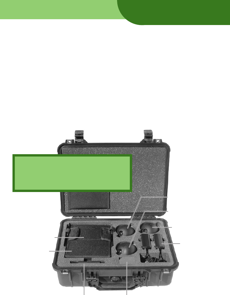
Remote Viewer #2
(RV2)
Training ball
Personal Display
Unit (PDU)
in pouch
Chargers (2)
Lens Brush
Charger AC
cords, carrying
strap and
manual
under PDU
Remote Viewer #1
(RV1)
Small parts and spares
IMPORTANT!
To obtain warranty service, you must mail the
Warranty Registration Card provided with the
Eye Ball RV1 System. You can also register
online at www.remingtonTD.com.

4
Remote Viewer
Slightly larger than a standard baseball. Can be tossed, rolled, dropped or lowered
into a hazardous location. Rugged construction prevents internal damage from
reasonable impact. (Note: The RV is not a breaching tool.)
Self-righting. Weighted base turns the RV upright from any orientation (unless there
are local obstacles).
Internal video camera provides 55° horizontal and 41° vertical field of view, and
user-controlled 2x digital zoom. Unlimited rotation in either direction enables full
360° surveillance.
Internal near-infrared (NIR) LEDs illuminate the scene. LEDs can be remotely set to
on, off or automatic (i.e., on or off as determined by the RV’s light sensor).
Internal microphone provides audio surveillance.
Powered by a rechargeable battery (up to 2 hours operation if illumination LEDs
are off, up to 2 hours operation if illumination LEDs are on, and up to 24 hours of
operation in Standby Mode).
Can be operated from charger (connected to 110/220VAC power source) for
continuous surveillance operations.
About
5
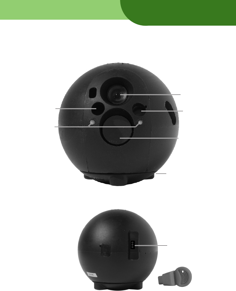
Microphone Auto
Illumination
Sensor
Illumination
LEDs
Camera
and Lens
Base
Front view
Ball Identifiers
(white = RV1,
black = RV2)
Rear view
Charging Jack (with
Pull Pin removed)
Pull Pin (remove from
Charging Jack when using
and charging RV)
About

6
About
Personal Display Unit
Lightweight handheld unit displays video received from one or two RVs, and
enables user to control one or two RVs.
Can be used up to 200 yards away from RV outdoors, line of sight; up to 40 yards
indoors through walls, floors and other obstructions.
Channel selection eliminates interference from other devices operating nearby.
Provides audio output through 3.5mm earphone jack.
Composite video output for connection to head up display or other video displays.
Powered by rechargeable battery (up to 3 hours of operation).
Can be operated from charger (connected to 110/220VAC power source) for
continuous surveillance operations.
Additional components supplied with the Eye Ball R1 include:
Two chargers (110/220VAC auto-sensing wall plug-in type).
PDU cover and shoulder sling.
Lowering wire adapter.
Pole/spike adapter.
Lens brush.
Cleaning cloth.
Spares: base screws, pull pins and lens cover.
Optional components (available from Remington Technologies Division,
301-208-8686, www.remingtonTD.com):
Telescoping pole.
RV spike.
RV duty belt and holsters.
Lowering wire holster.
Canvas carrying case.
Additional pull pins.
7
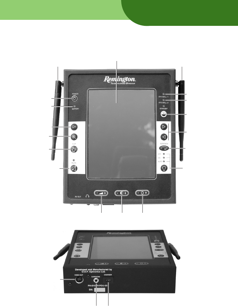
Bottom view
S-Video
Output Jack
(for use with
head-up display)
Charging JackHeadphone Jack
About
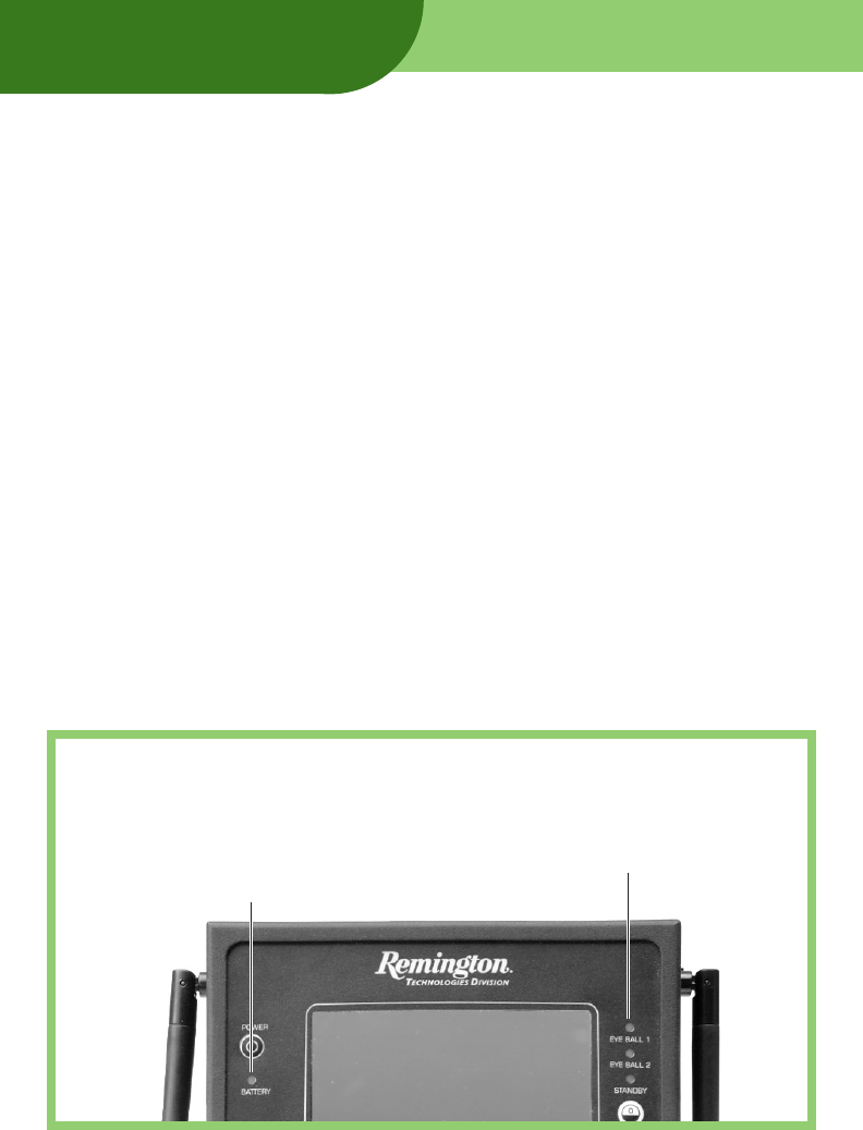
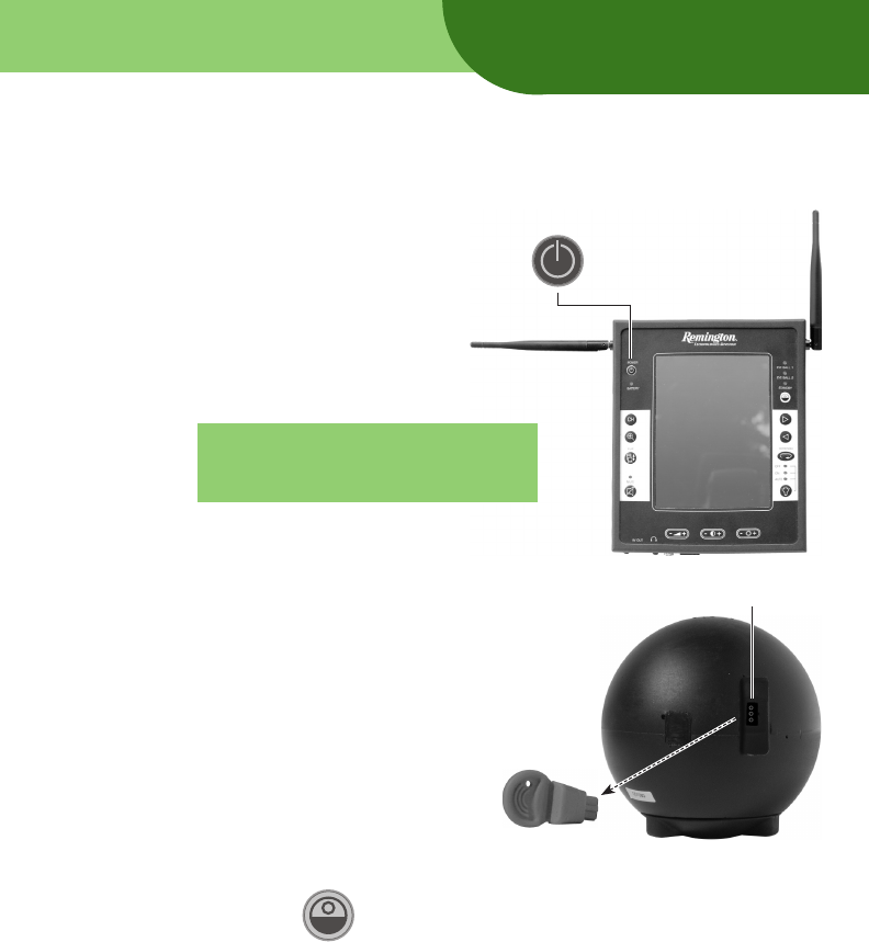
Front view
Data antenna
(shown in storage position)
Power
Display
Standby
Illumination
(off by default)
Channel Select
Zoom
Continuous
Rotation On/Off
Rotation
Direction
and Nudge
Mute
(on by default)
Volume BrightnessContrast
Video/audio antenna
(shown in storage position)
RV1 Status
RV2 Status
PDU Battery
Status
Flip View
8
Charging Jack
Using a charger
IMPORTANT: Use the chargers only within a temperature
range of 32°F to 113°F (0°C to 14°C).
Tip: The two chargers are identical. They can be used to
charge both the PDU and RVs.
Before charging: Attach the power cord to the charger. Do not connect the charger
to a power receptacle until directed to do so in the charging instructions.
After charging: Detach the power cord from the charger. Store the charger and
power cord in the R1 carrying case.
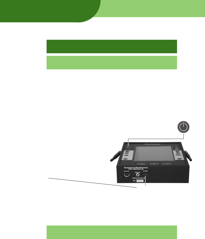
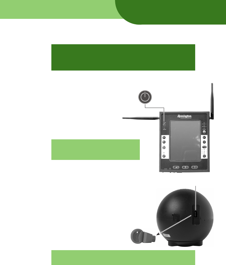
To charge the Personal Display Unit
1. If the Personal Display Unit (PDU) is on, turn it off: press the Power button
(in the upper left corner) for 2 seconds.
2. Connect the Charger Plug to the PDU’s
Charging Jack.
3. Plug the Charger into a 110 or 220VAC
receptacle (the charger automatically
adjusts to the available voltage).
4. Charge the PDU for at least 5½ hours. Charger LED is red during charge, and green
when finished. Charging will stop automatically when the battery is fully charged.
Tip: You can use the PDU while it is charging, but the PDU
must be off when the charger is first turned on.
5. Remove the Charger from the receptacle.
6. Disconnect the Charger Plug from the PDU.
Charging
9
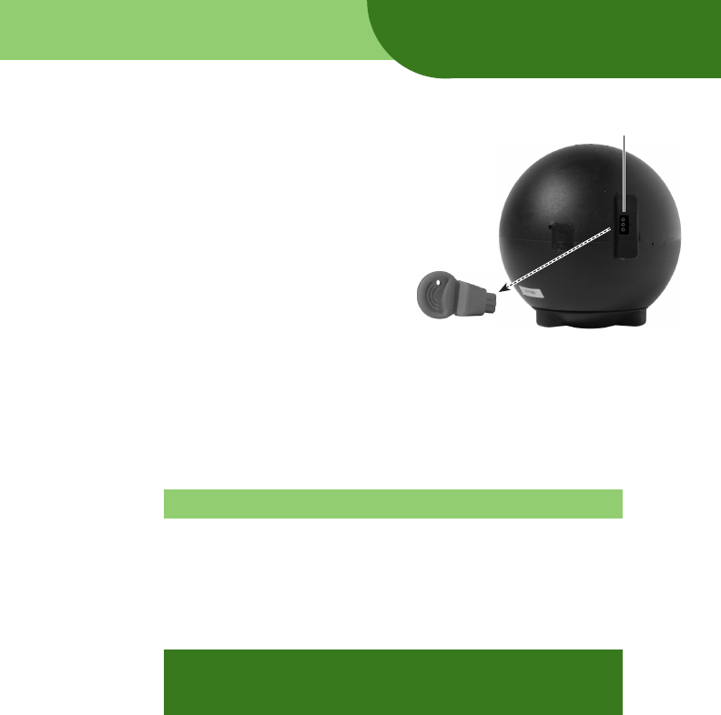
Charging Jack
Pull Pin
To charge a Remote Viewer
1. Remove the Pull Pin from the Charging Jack
on the rear of the RV.
Removing the Pull Pin turns on the RV. The
Illumination LEDs will flash briefly.
2. Connect the Charger Plug to the RV’s Charging Jack.
3. Plug the Charger into a 110 or 220VAC receptacle (the charger automatically adjusts
to the available voltage).
4. Charge the RV for at least 2 hours. Charger LED is red during charge, and green
when finished. Charging will stop automatically when the battery is fully charged.
Tip: You can use the RV while it is charging.
5. Remove the Charger from the receptacle.
6. Disconnect the Charger Plug from the RV.
7. Insert the Pull Pin in the Charging Jack on the rear of the RV.
IMPORTANT: When charging is complete, you must insert
the Pull Pin in the Charging Jack to turn off the RV. If you
leave the Pull Pin out the RV will discharge.
Charging
10
Five sections in this chapter provide step-by-step instructions for using the Eye Ball R1
System:
A. Check operation
B. Deploy the Remote Viewer
C. Optimize video reception
D. Control the Remote Viewer
E. Complete the mission
Using
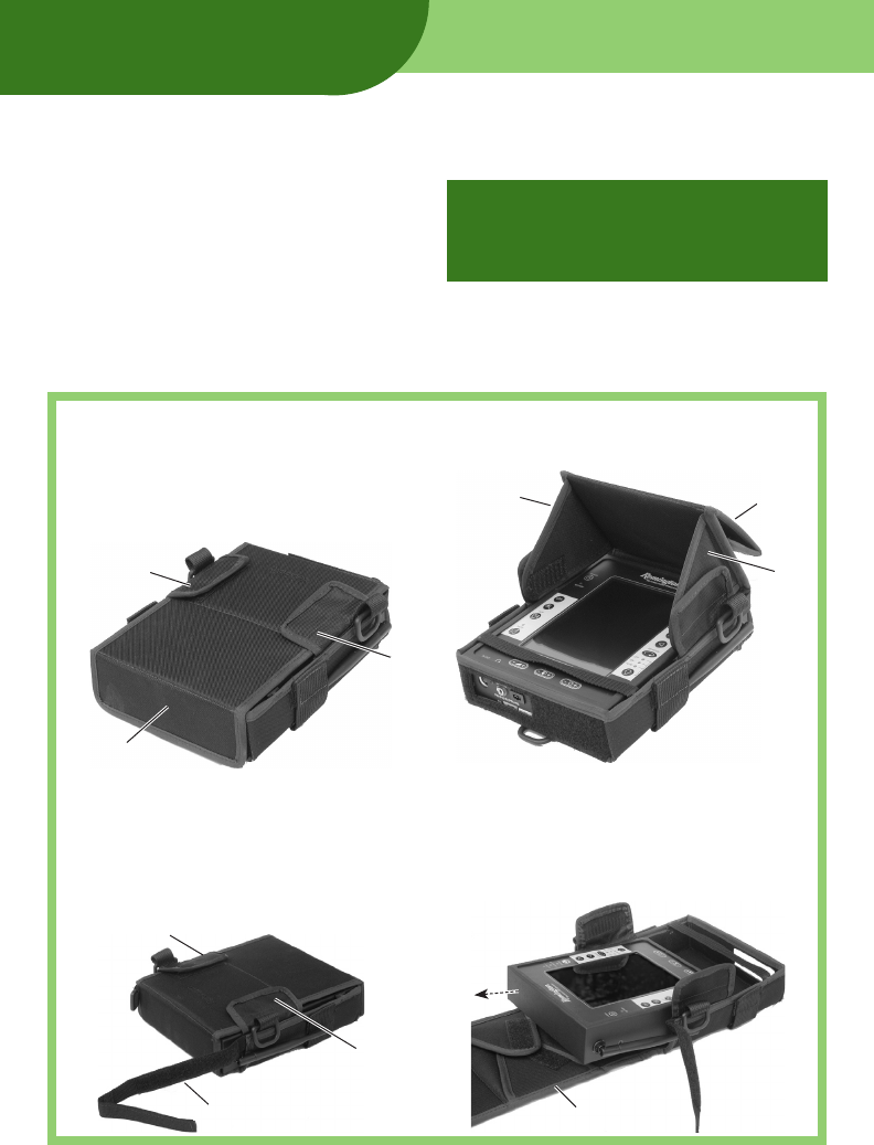
Removing the PDU from the pouch
1. Release strap across top of pouch.
2. Release side flaps.
3. Release and unfold front flap.
4. Slide PDU out of pouch.
Setting up the PDU hood
1. Release and lift side flaps.
2. Release and lift front flap.
3. Unfold inner flaps and stick them to side flaps.
4. Fold front flap back and stick it to itself.
3
3
4
1
1
2
IMPORTANT: Before using the Eye Ball
R1 System for the first time, charge the
PDU and both RVs. Instructions are in
the previous chapter.
1
2
2
3
4
11
A. Check operation
If the Eye Ball RV and PDU are fully charged, they should
be ready for use at any time (see section B). If conditions
permit, however, check system operation before deploying
the Remote Viewer.
1. Remove the Remote Viewer (RV) and the Personal Display Unit (PDU) from their
carrying case.
2. Turn on the PDU: press and hold the Power button (in the upper left
corner) for about 2 seconds.
3. Rotate the PDU antennas into the
approximate positions shown at right.
Notice: PDU antennas should be held at a minimum of 7.9 inches (20 cm) or more from the body of all users.
Note: Leaving the antennas folded
along the PDU sides drastically
reduces operating range.
4. Turn on one of the RVs: remove the Pull Pin from
the rear of the RV. The RV initializes, during which:
Illumination LEDs flash briefly.
RV transmits video and audio for about
2 seconds.
RV rotates right, then left.
RV enters Standby mode.
5. Repeat step 4 for the other RV.
Note: The Eye Ball R1 System is now ready for use. To
perform a more thorough check, continue with steps 6–13.
Using
continued
Charging Jack
Pull Pin
IMPORTANT: Before using the Eye Ball
R1 System for the first time, charge the
PDU and both RVs. Instructions are in
the previous chapter.
12
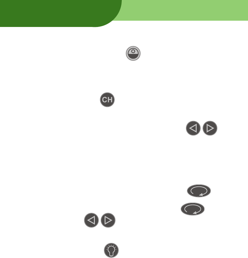
6. Select one RV: press the Standby button once, quickly (each press toggles
between the RVs).
If you don’t see video from the RV, verify that the RV and PDU are charged.
If there is video interference:
Reorient the video/audio antenna (on the right side of the PDU).
Press the Channel button on the PDU. (Each RV can operate on one of
four radio channels.)
7. Verify RV movement:
a. Nudge the RV by about 10º: momentarily press one Direction
button.
b. Repeat step a for the other direction.
c. Nudge the RV by about 30º: press one Direction button for about 2 seconds.
d. Repeat step c for the other direction.
8. Verify RV rotation:
a. Initiate continuous rotation: press the Rotation On/Off button .
The RV should rotate in the direction it was last nudged.
b. Stop continuous rotation: press the Rotation On/Off button , or
press either Direction button.
9. Verify illumination operation:
a. Place the RV in a dark area.
b. Press the Illumination button on the PDU to turn the Illumination LEDs on
(as indicated above the button). You should see the scene clearly on the PDU.
c. Press and hold the Illumination button (about 2 seconds) to select Auto
Illumination Mode (as indicated above the button). You should see the scene
clearly on the PDU.
Using
continued

13
d. Press the Illumination button to turn the Illumination LEDs off.
Tip: The RV camera is extremely sensitive, and illumination
may not be required in some low-light situations. Thus, there
may not be a noticeable change between images with and
without illumination.
10. Verify audio operation:
a. Verify that muting is off: the Mute Indicator (just above the Mute button)
should be off. If the Mute Indicator is on, press the Mute button once.
b. Plug headphones into the Headphone Jack on the PDU’s bottom panel. Have a
helper take the RV a few yards away and speak into the microphone on the front
of the RV. You should hear the helper’s speech in the headphones.
c. If you don’t hear audio, press the + button on the Volume Control to
increase audio volume. Test audio again.
11.
Check communication range:
a. Have a helper hold the RV and walk away from the PDU while you watch the
video image. You and the helper should be able to directly see each other during
this range check.
b. When the video image becomes poor, tell the helper to stop walking. Adjust the
antennas for best reception, then tell the helper to walk farther. When the video
image becomes poor, have the helper walk back toward you about 4 yards and
stop. This is the maximum reliable operating range for the Eye Ball R1 system
under good conditions.
Note: Useful range will vary depending on the presence of
walls, floors, vehicles and other obstructions, as well as PDU
antenna orientation, and distance between the PDU and RV.
Using
Common problems
If an RV fails to respond to a command, or if you see video from two RVs at the
same time, simply reissue the last command.
continued
14
12. Repeat steps 6 through 11 with the other RV.
13.
If you will not be using the system immediately:
a. Turn off the RVs.
b. Turn off the PDU.
Using
Status indicators
PDU Status Indicator
Fast flashing: PDU is communicating with an RV.
Pressing a PDU button during this time has no
effect.
Slow flashing: battery will power PDU for about 1
hour; if 120VAC is available, you can power PDU
using the Charger.
RV Status Indicators
Slow flashing: battery will power RV for
about 20–30 minutes.
Flashing only appears when the RV
is active.
15
Using
B. Deploy the Remote Viewer
1. Remove the Remote Viewer (RV) and the Personal Display Unit (PDU) from their
carrying case.
2. Turn on the PDU: press and hold the Power button (in the upper left
corner) for about 2 seconds.
3. Rotate the PDU antennas into the
approximate positions shown at right.
Notice that the antennas are not parallel.
Note: Leaving the antennas folded
along the PDU sides drastically
reduces operating range.
4. Turn on one of the RVs: remove the Pull Pin from
the rear of the RV. The RV initializes, during which:
Illumination LEDs turn on constantly or flash
(flashing indicates battery is nearly depleted,
and will power the RV for about ½ hour or less).
RV transmits video and audio for about
2 seconds.
RV rotates right, then left.
RV enters Standby mode.
5. Repeat step 4 for the other RV.
6. Press the Standby button once or twice to display video from the RV.
7. Verify that the PDU is receiving video from the RV.
continued
Charging Jack
Pull Pin
16
Using
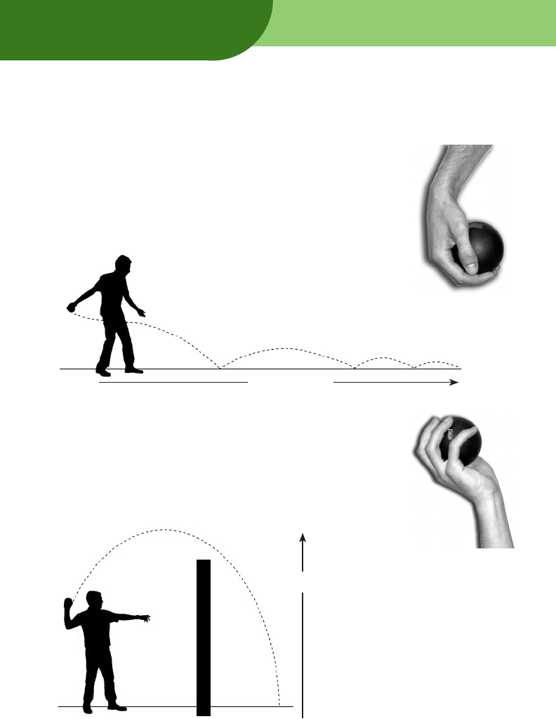
8. Deploy the RV as close as possible to the area of interest. You can:
Roll the RV into position.
When deploying the RV to a distant location (about 75 feet),
this method often results in the most accurate placement.
Hold the RV firmly as shown in the photo at right, then toss
it horizontally toward the destination (similar to throwing a
bowling ball) as shown below.
Toss the RV into position.
This method is useful when deploying the RV over a wall
or fence, or through an open window. Hold the RV firmly
as shown in the photo at right, then throw it upward at a 45º
angle toward the destination (similar to throwing a grenade)
as shown below.
continued
About 75 feet
About 7½ feet

17
Using
Note: The RV is not a breaching tool.
Note: Do not start rotation while the RV is in motion, as this
could damage the rotation mechanism. Wait until the RV is
in position to begin rotation.
Lower the RV into position. See “Lowering Wire Adapter” on page 20.
Raise the RV into position. See “Telescoping Pole” on page 20.
9. When the RV is in position, observe the video on the PDU. If you think the RV is
not upright, rotate it using the Rotation On/Off button . Rotating should
help the RV to roll onto its base.
C. Optimize video reception
If video from a selected RV is poor or not present:
Reorient the video antenna (on the right side of the PDU).
Move the PDU to a different location to minimize the effects of walls, floors,
vehicles and other obstructions.
Move the PDU closer to the selected RV.
18
Using
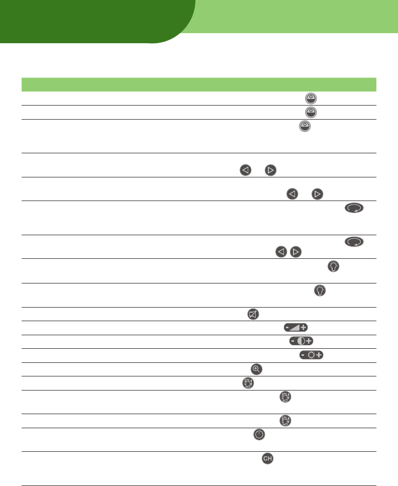
D. Control the Remote Viewer
To do this... Do this...
Switch between RVs Momentarily press Standby button .
Resume operation from Standby Momentarily press Standby button to select RV.
Reduce RV power consumption
when video isn’t needed
Press and hold Standby button (about 3
seconds) until Standby indicator is on (places
both RVs in Standby Mode).
Nudge RV about 10° While RV is not rotating, momentarily press a
Direction button or .
Nudge RV about 30° While RV is not rotating, press and hold (about 2
seconds) a Direction button or .
Start continuous rotation Momentarily press Rotation On/Off button .
(Rotation will be in last direction in which RV was
nudged.)
Stop continuous rotation or scan Momentarily press Rotation On/Off button
or either Direction button .
Turn illumination on or off Momentarily press Illumination button until
indicator shows desired state.
Set illumination to auto Press and hold Illumination button until Auto
indicator turns on.
Mute or hear audio Press Mute button .
Adjust audio volume Press – or + Volume button .
Adjust video contrast Press – or + Contrast button .
Adjust video brightness Press – or + Brightness button .
Zoom in or out Press Zoom button .
Flip display vertically Press Flip button .
Turn off display to conserve
power
Press and hold Flip button for 5 seconds.
Turn on display Press and hold Flip button for 1 second.
Turn off PDU and place RVs in
standby
Press Power button .
Change channel to optimize
video/audio or avoid interfering
with another device
Press Channel button (there are 4 channels).
19
Using
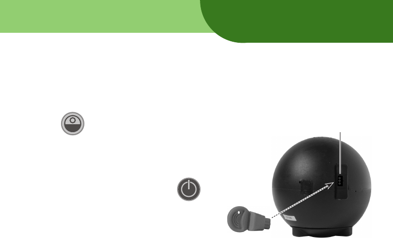
E. Complete the mission
1. When the RV deployment area is safe, retrieve all deployed RVs.
2. Switch system to Standby Mode: press and hold (about 3 seconds) the Standby
button until the Standby indicator turns on.
3. Turn off the RVs: insert the Pull Pins
into the Charging Jacks.
4. Turn off the PDU: press and hold
(about 2 seconds) the Power button .
5. As soon as possible, recharge the
PDU and RVs, so they will be
ready for the next mission.
Charging Jack
Pull Pin
20
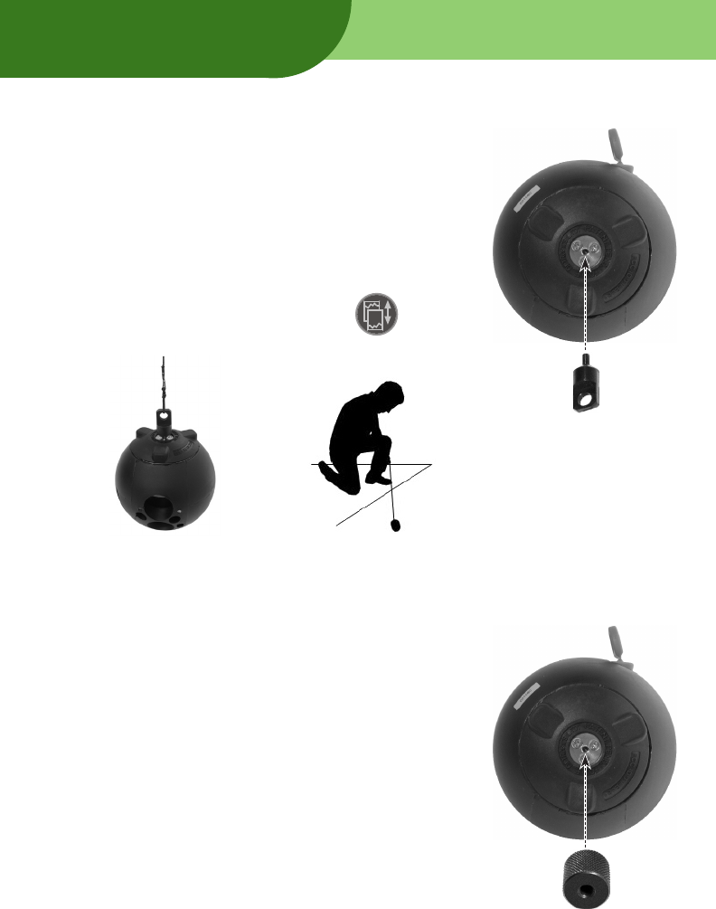
Lowering Wire Adapter
Use a lowering wire to perform surveillance from above a
scene.
1. Thread the Lowering Wire Adapter into the center hole
in the RV’s base. Tighten gently.
2. Securely attach a wire or string to the Adapter.
3. Lower the RV into the surveillance location.
4. On the PDU, press the Flip View button to view
the image right side up.
Using
Telescoping Pole
Use the Telescoping Pole to raise the RV to a higher position
and to bypass obstacles.
1. Thread the Pole Adapter into the center hole in the RV’s
base. Tighten gently.
2. Thread the Telescoping Pole into the Pole Adapter.
3. Move the RV into position with the Telescoping Pole.
Lowering Wire
Adapter
Pole Adapter

21
Training is essential for rapid and effective use of the Eye Ball R1 System during field
operations. This section suggests exercises to help users become familiar with Eye Ball
procedures, functions and deployment.
General system operation
Work with the RV nearby so you can see how the PDU’s controls affect the RV:
Learn how to set up the PDU hood.
Learn how to turn the RV on and off by removing and replacing the Pull Pin.
Learn how to turn the PDU on and off.
Learn how to check system operation.
Review and understand all PDU controls.
Learn how to control the RV with the PDU.
Learn how to charge the RV and PDU.
Deploy the Remote Viewer
The Training Ball is the same size and weight as the Remote Viewer, but it does not
contain electronics. Use the Training Ball during rolling, tossing, dropping and lower-
ing exercises.
Learn how to roll the Training Ball.
Learn how to toss the Training Ball.
Learn how to drop the Training Ball.
Learn how to lower the Training Ball using a lowering wire.
Learn how to elevate the Training Ball using the Telescoping Pole.
Simulate field operations
Work with the real RV and PDU to:
Learn how to deploy the RV so you can see what is around a corner.
Learn how to deploy the RV so you can see what is in an enclosed area, such as
inside a garage or in a fenced yard.
Learn how to deploy the RV through an open door or window so you can see what is
inside a room.
Training

22
Maintaining
Post-use maintenance
After each use:
Clean each RV’s external rubber surfaces with a clean cloth.
Clean each RV’s lens and illumination window with a lens cleaning cloth.
Make sure each RV’s base screws are tight.
Charge the PDU and both RVs.
Scheduled charging
IMPORTANT: Fully charge the PDU and both RVs every
three months. If this regular charging isn’t performed, the
units may be permanently damaged.
Internal inspection and cleaning
The Remote Viewer should be inspected and cleaned at the following times:
If the RV does not rotate, or rotates sluggishly, when directed by the PDU.
If the RV was exposed to mud, water, sand or heavy dust.
As part of annual preventive maintenance.
1. Using a Philips screwdriver, remove three screws securing the RV’s base.
2. Remove the base.
3. Clean accumulated dust, sand and dirt from the lower surface.
IMPORTANT: The RV is fully sealed. Do not lubricate!
4. Replace the base, then secure it using the three screws removed in step 1.
Note: For all other maintenance operations, return the
system to Remington Technologies Division for service.
Maintenance records
Use the table on the next page to record maintenance activities.

23
Maintenance record
Date Inspected Cleaned lens Cleaned base* Performed by
*Required only if RV deployed in dusty, sandy or muddy environment.
Maintaining

5 Choke Cherry Road, Suite 185
Rockville, MD 20850 U.S.A.
Phone: 301-208-8686
Fax: 301-208-8964
Web: www.remingtonTD.com
© 2005 Remington Technologies Division.