OEM Controls ST511 ST-511 Radio Primary User Manual Contents
OEM Controls, Inc. ST-511 Radio Primary Contents
User Manual
ii
10 Controls Drive, Shelton CT 06484
203.929.8431
www.oemdd.com
WARNING: It is the purchaser’s responsibility to determine the suitability of any OEM
Controls, Inc. product for an intended application and to ensure that it is installed and guarded in accordance
with all federal, state, local and private safety and health regulations, codes and standards.
We can advise you of the various features that are available, but we believe that our customer’s engineering
departments should be qualified experts in their own product field. If the product will be used in a safety critical
application, the customer must undertake appropriate testing and evaluation to prevent injury to the ultimate
user.
Should you have any questions or if any of the above warning is unclear, please contact OEM Controls, Inc. at
10 Controls Drive, Shelton, CT, 06484, FAX: 203.929.3867, TEL: 203.929.8431
WARNING: Changes or modifications not expressly approved by the party responsible for
compliance could void the user’s authority to operate the equipment.
NOTE: This equipment has been tested and found to comply with the limits for a Class A digital device,
pursuant to part 15 of the FCC Rules. These limits are designed to provide reasonable protection against harmful
interference when the equipment is operated in a commercial environment. This equipment generates, uses, and
can radiate radio frequency energy and, if not installed and used in accordance with the instruction manual, may
cause harmful interference to radio communications. Operation of this equipment in a residential area is likely to
cause harmful interference in which case the user will be required to correct the interference at his own expense.
This device complies with part 15 of the FCC Rules. Operation is subject to the following two conditions: (1) This
device may not cause harmful interference, and (2) this device must accept any interference received, including
interference that may cause undesired operation.
This equipment complies with the FCC RF radiation exposure limits set forth for an uncontrolled environment.
This equipment should be installed and operated with a minimum distance of 20 centimeters between the
radiator and your body.
This device complies with Industry Canada licence-exempt RSS standard(s). Operation is subject to the following
two conditions: (1) this device may not cause interference, and (2) this device must accept any interference,
including interference that may cause undesired operation of the device.
Le présent appareil est conforme aux CNR d'Industrie Canada applicables aux appareils radio exempts de
licence. L'exploitation est autorisée aux deux conditions suivantes : (1) l'appareil ne doit pas produire de
brouillage, et (2) l'utilisateur de l'appareil doit accepter tout brouillage radioélectrique subi, même si le brouillage
est susceptible d'en compromettre le fonctionnement.

iii
Contents
Section 1 1
Overview of the Mobile GoPOD Secure Fueling System .................... 1
The ST-542 Human Machine Interface (HMI) ....................................................................................................... 3
The Mobile STI GoPOD Assembly ........................................................................................................................ 3
Secure Fuel Bypass Controller STOB-100 ............................................................................................................. 4
Automated Ball Valve ............................................................................................................................................ 5
The Mobile GoPOD Secure Fueling Antennas ....................................................................................................... 6
Mobile GoPOD Complimentary Equipment .......................................................................................................... 7
Section 2 8
Installation Guidelines ........................................................................ 8
Mobile GoPOD Secure Fueling System ................................................................................................................. 8
Mobile GoPOD System Wiring Configuration....................................................................................................... 9
The GoPOD Electrical Connections ..................................................................................................................... 10
The Battery Cable for GoPOD ...................................................................................................................... 11
Power Supply Requirements ................................................................................................................................. 11
Installing the GoPOD CPU ................................................................................................................................. 12
ST-542 Outline Dimensions and Interface Connectors ........................................................................................ 13
Mounting the ST-542 (HMI) ................................................................................................................................ 14
Before starting: .............................................................................................................................................. 14
Installing the GPS Antenna .................................................................................................................................. 15
Electrical Wiring Termination for GPS Antenna .......................................................................................... 15
The Radio Antenna Installation Guidelines .......................................................................................................... 16
Installing the Secure By-Pass Controller .............................................................................................................. 17
Section 3 18
Testing and Troubleshooting ............................................................ 18
HMI (ST-542) Troubleshooting ........................................................................................................................... 18
Quick Check – For the STI GoPOD CPU ............................................................................................................ 18
IF – THEN: Using ST1-CPU LEDs to Diagnose the System ....................................................................... 19
Troubleshooting the Automated Ball Valve ......................................................................................................... 19
Using the Secure Fuel Controller to Troubleshoot ............................................................................................... 20
Section 4 21
Fueling with the HMI Touch Screen ................................................. 21
Selecting or Entering the Equipment Number ............................................................................................... 21
Using a Secure System Without a Service Tracker ....................................................................................... 21
Entering Data in a Secure System With a Service Tracker ........................................................................... 22
Mobile GoPOD Secure Fueling System Block Diagram ...................................................................................... 24
Section 5 25
Index ................................................................................................. 25
Figures
Figure 1.- Mobile GoPOD Secure Fueling Modules .............................................................................................. 2
Figure 2.- ST-542(HMI) ......................................................................................................................................... 3
Figure 3.- STI GoPOD Assembly ........................................................................................................................... 4
Figure 4.- Automated Ball Valve ............................................................................................................................ 5

Contents –STIB 22637 Rev. A
iv
Figure 5.- The Mobile GoPOD Secure Fueling Antennas ...................................................................................... 6
Figure 6.- Installation Guidelines ........................................................................................................................... 8
Figure 7.- Mobile GoPOD System Harness Installation ......................................................................................... 9
Figure 8.- The GoPOD Electrical Installation ...................................................................................................... 10
Figure 9.- Battery Cable Connection Instructions ................................................................................................ 11
Figure 10.- Installing the GoPOD Assembly ........................................................................................................ 12
Figure 11.- ST-542 Outline and Dimensions ........................................................................................................ 13
Figure 12.- GPS Antenna Installation Instructions ............................................................................................... 15
Figure 13.- GoPOD Radio Antenna ST-511 Installation Instructions .................................................................. 16
Figure 14.- Secure Fueling Controller STOB-100 Installation Instructions ......................................................... 17
Figure 15.- Troubleshooting the Secure Fuel Controller and Automated Ball Valve ........................................... 20
Figure 16.- Using the HMI to Fuel ...................................................................................................................... 23
Figure 17.- Mobile GoPOD Secure Fueling System Block Diagram ................................................................... 24
Document Revision History
OEM Controls Inc; All rights reserved.
Disclaimer and Limitation of Liability
Document Number:
Revision: B
Date of Release: 4/26/2011
About this guide:
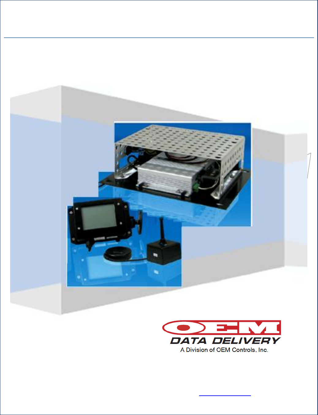
This guide provides basic instruction on the installation and use of the Mobile GoPOD Secure Fueling System.

| Confidential and Proprietary, Property of OEM Data Delivery a Division of OEM Controls, Inc| |
Section 1
1
Section 1
Overview of the Mobile GoPOD Secure
Fueling System
This document will serve the user of this equipment as a Manual of Operations and
basic troubleshooting guide, thereby allowing for the proper installation and use of
the of Mobile GoPOD Secure Fueling System.
The Mobile GoPOD system contains a group of stand- alone modules built by OEM
Data Delivery, Inc. that have been combined and engineered to provide the user with
complete system of mobile product delivery and information gathering.
In addition to controlled product dispensing, the system records information on
location, equipment being maintained, date/time, type of work and the specific task or
reason for service.
The heart of system is the STI GoPOD CPU module. It operates wireless and hands-
free to collect information passively, via drive-by, within a range of 200 ft. line of
site, and transmits data via secure radio link. It is then formatted, downloaded into a
web report each night, and made available on a password-protected website.
The system will track disposition of equipment and indirect costs and can be
configured for data management to generate e-mail alerts for specific events or
benchmarks i.e. maintenance is due, warranty is about to expire.
There is a Secure Fuel software option, visible to the operator at the ST-542 (HMI)
(Human Machine Interface) display. This Password required option is designed for
real-time tracking of dispensed product and will prevent theft or unauthorized use of
the system.
The By-Pass Key Controller module, in this system, is a hardwired option that serves
as a failsafe measure in the case of a computer failure, or system miscue by switching
to the system to battery power directly and allowing the operator to complete the
required transaction.
The system was designed to allow for user flexibility at the installation process.
Modules that make up the system can be placed in the most convenient location, for
the user, due to the flexible interconnecting wiring scheme and design philosophy.
The system will allow for additional information gathering pieces or dispensing
modules without compromising the basic design.
This document provides coverage for the following components: ST-542 (HMI), STI
GoPOD Assembly, ST-511 Radio Antenna, ST-560 GPS Antenna, and the
Automated Ball Valve.
Contents –STIB 22637 Rev. A
2
Section 1 | Overview and Technical Specifications
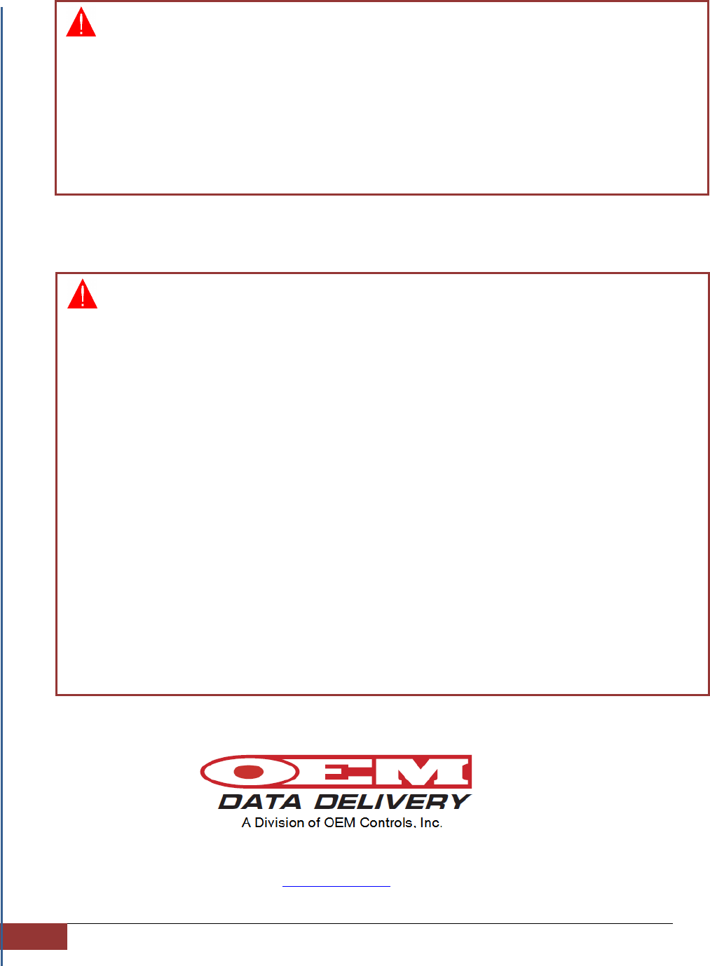
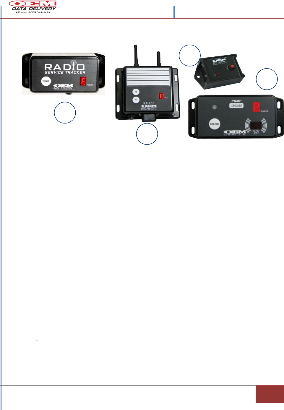
Figure 1.- Mobile GoPOD Secure Fueling Modules
Mobile GoPOD Secure Fueling System Assembly
PIN #
Description
OEM Part Number
Qty
1
HUMAN MACHINE INTERFACE (HMI) ST-542
ST-542-103
1
2
GPS ANTENNA WITH CABLE ASSEMBLY
ST-560-GPS
1
3
GPRS CELLULAR ANNTENA
CBA-3KT
1
4
RADIO ANNTENA
ST-511
1
5
GoPOD CPU ASSEMBLY
STI
1
6
SECURE BY-PASS CONTROLLER
STOB-100
1
7
AUTOMATED BALL VALVE &
ACTUATOR
DE305H
1
4
5
2
1
3
6
7
Contents –STIB 22637 Rev. A
Confidential and Proprietary, Property of OEM Data Delivery a Division of OEM Controls Inc.|
Section 1
3
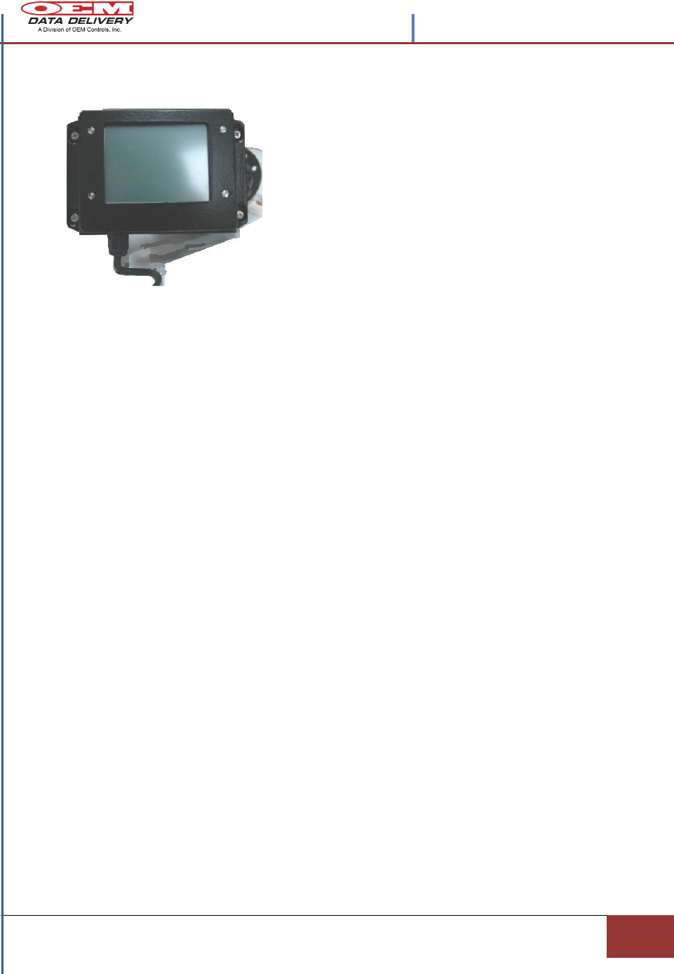
The ST-542 Human Machine Interface (HMI)
Display Type QVGA TFT LCD
Colors 18 bits (256 k)
Resolution 320 x 240
Size (diagonal) 5.87” (4:3)
View Angle (H°, V°) H: 140°, V: 120°
Brightness 320 nits by LED backlight
Touchscreen 4-wire resistive
Contrast Ratio 500
The ST-542-200 is a rugged LCD touch screen display that allows the operator to
directly interface, in real time with the operating Serial Pump Tracker GoPOD CPU,
through an OEM Data Delivery, Inc. design feature called the Human Machine
Interface (HMI).
This four (4) line- twenty (20) character LCD display, built by OEM Data Delivery,
Inc., is configured by the software and hardware links, to allow the operator to
directly input to and view all of the processes’ for the selected pump, as they are
happening, in real time.
This rugged LCD display must be hardwired to its GoPOD CPU. It should be
mounted as recommended, no more than 35 feet from the STI-GoPOD CPU with the
harness supplied by OEM Data Delivery, Inc., at a height convenient for the operator.
See the Block Diagram at Figure (2) for installation placement recommendations.
Figure 2.- ST-542(HMI)
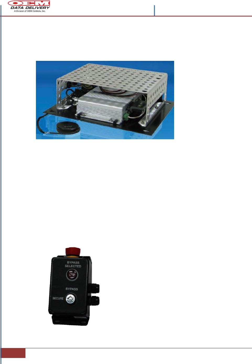
The Mobile STI GoPOD Assembly
This STI-GoPOD unit is the control center of the Serial Pump Tracker System.
The GoPOD assembly houses a ruggedized CPU configured with 512 MB Memory, 1
GB CF, Windows XP Embedded for ease of use. The fan-less housing was designed
to be installed in the cab of a lube or fuel truck, low boy truck, mechanics’ truck, or
supervisor’s vehicle. It is easily installed under the dash in the cab or on the passenger
side firewall or behind any seat. STI GoPOD is equipped with a GPS antenna, and a
radio antenna. Information is collected passively, and “hands-free”. GPS coordinates
are automatically stamped into the record as hourly data is collected. Information is
collected via drive-by, within a range of 300 ft. line of site, and transmitted via that
secure radio link.
From its external modem data is then downloaded into a web report each night, via
cellular WIFI connectivity and made available on a password-protected website.
Information easily integrates with any major back office management system and
Contents –STIB 22637 Rev. A
4
Section 1 | Overview and Technical Specifications
with dedicated ports on the CPU, for communication, there is never an interruption of
equipment operation.
At the GoPOD core is an Intel Celeron microprocessor that is equipped with (2x) RS-
232/422/485 ports by BIOS selectable, and (4x) USB ports. The 600MHz CPU allows
for real time updates when the operator is dispensing or capturing product.
Figure 3.- STI GoPOD Assembly
Secure Fuel Bypass Controller STOB-100
This key operated electro-mechanical controller option allows the user a second degree of
security, when wired between the GoPOD CPU and the Automated Ball Valve. (See Figure
7.- Installation Guidelines)
The Secure Fuel Bypass Controller sits in a passive state until the key switch is activated. At
that point power is applied directly to the Automated Ball Valve, in this system, and the
operator is able to complete the delivery manually.
The controller serves as a failsafe measure in the case of a
computer failure, or system miscue by switching to the
battery power directly and allowing the operator to complete
the required transaction.
It should not be used as a convenient method of product
delivery, from battery to pump, without computer control.
This override system will not record the transaction; it only
serves to complete the delivery in a timely manner.
It allows for convenient testing of the system, when time
allows and without the GoPOD CPU, without the stress of
delivery schedules.
Technical Specifications
Environment
• Temperature: -40 to
+70°C operating
Weather Resistance
• Sealed and tested for
dust and
water resistance to IP-65
or greater
GoPOD
• Power Consumption:
Typical wattage when
operating 13.5W
• Input Voltage: DC 9V ~
35V
Data Format
• Comma-Separated Value (CSV), Extensible
Markup Language (XML), Open Database
Connectivity (ODBC), and others.
Connectivity
• Cellular
• WiFi
Contents –STIB 22637 Rev. A
Confidential and Proprietary, Property of OEM Data Delivery a Division of OEM Controls Inc.|
Section 1
5
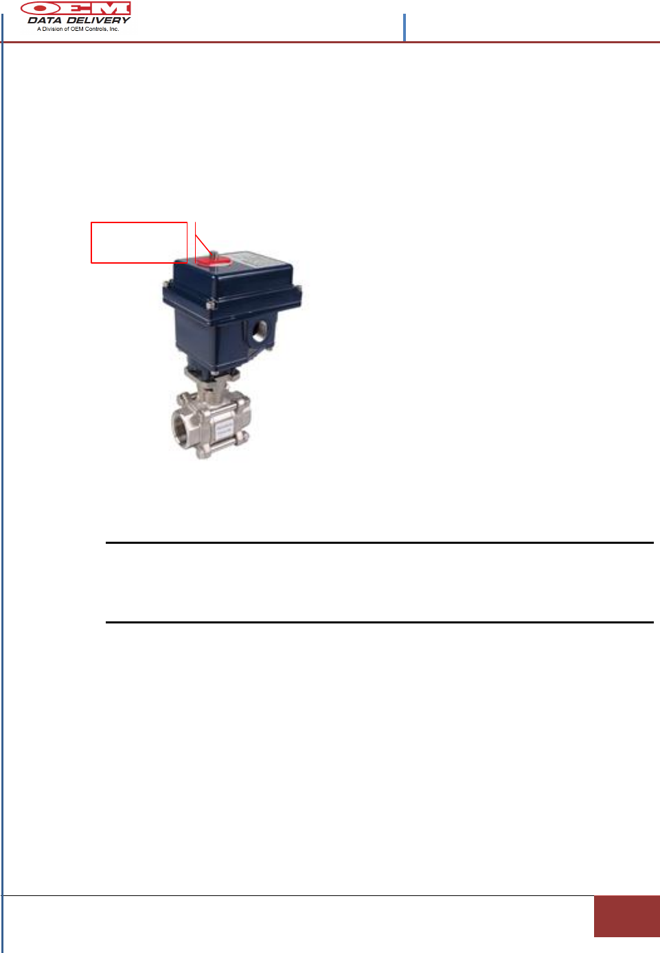
Automated Ball Valve
The Automated Ball Valve in the Service Tracker Pump System operates as the
computer driven, electronic controller between the product pump and the GoPOD CPU.
It operates as a secure fueling station when used in conjunction with the Secure Fuel
Bypass Controller. As configured in this system it operates with (+) 12VDC input
voltage.
This actuator can be mounted in any direction without consequence, however,
determine that the actuator, open or closed, matches the position of the equipment to
which it is mounted. Use the manual override to change the position, if necessary.
Note: Wiring power to terminals 1 & 2 will cause the camshaft to rotate counter -
clockwise. Rotating counter-clockwise opens the valve.
Wiring power to terminals 1 & 3 will cause the camshaft to rotate clockwise.
Rotating clockwise closes the valve.
1. Install the ball valve and actuator to a valve bracket or damper, ensuring that the
base of the actuator is flush with the top plate.
2. Insert bolts but do not tighten.
3. Use the manual override to move the stem of the valve or damper slightly to
correct for side thrust or misalignment.
4. Manually place the valve to either full travel positions and tighten the bolts using
a cross pattern scheme and equally draw the bolts down to finish.
Figure 4.- Automated Ball Valve
Modulating Controls
Accepts 0 - 5 VDC , or 0 - 12 VDC
control signal to position the valve at
various degrees of open/close.
Fail-Safe Backup
Battery backup system that allows
normal operation of actuator with 120
Volt AC but converts battery DC to AC
upon incoming AC power failure.
Spring-Return Fail-Safe
Fail-safe spring back-up system within
the electric actuator takes over upon loss
of power.
MANUAL
OVERRIDE
Contents –STIB 22637 Rev. A
6
Section 1 | Overview and Technical Specifications
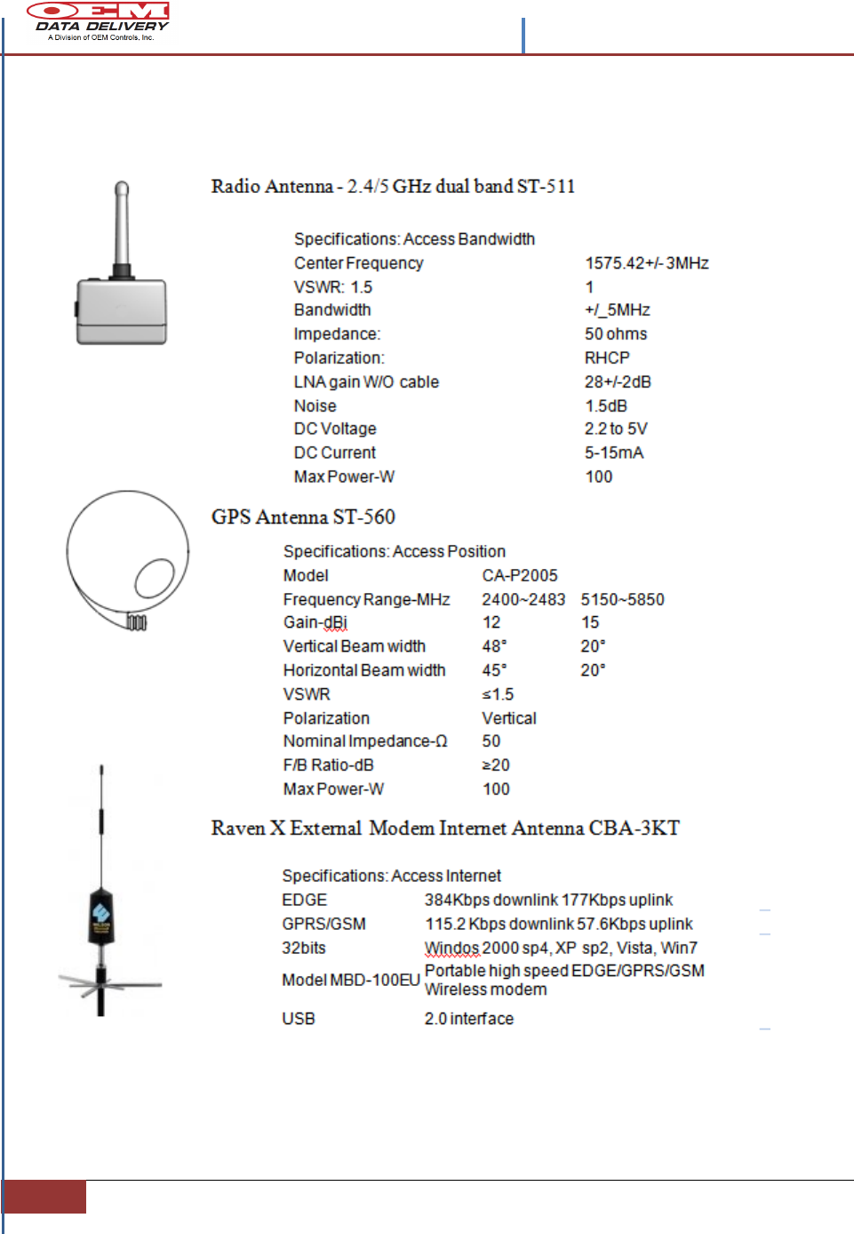
The Mobile GoPOD Secure Fueling Antennas
Figure 5.- The Mobile GoPOD Secure Fueling Antennas
Contents –STIB 22637 Rev. A
Confidential and Proprietary, Property of OEM Data Delivery a Division of OEM Controls Inc.|
Section 1
7
Mobile GoPOD Complimentary Equipment
1. ST-550 Radio Service Tracker: In the operation mode, an ST-550 mounted on the dash
board or on the top of a vehicle, has been logging in CMH (Cumulative Machine Hours), and
compiling maintenance service times on the vehicle. Each maintenance procedure is assigned
a Service Tracker number (up to seven different procedures can be tracked). The maintenance
issues are displayed as service alerts. Each service alert has a designated identifier number
(one through seven) that display on the “Power Box” of the ST-550. The number indicates
that a particular maintenance procedure should be completed. When the service alert is
satisfied the counter is reset with any supporting PDA (Personal Data Assistant). Retrieving
the ST-550 data, such as the profile, service alerts, work/ idle/ run/ count/duration logs is
accomplished with a supporting PDA.
2. ST-900 Service Tracker: is designed with GPS and cellular communications. It tracks
equipment activity at utility construction sites and during service calls, so that PTO (Power
Take-Off) credits can be obtained quickly for fuel used at the work site. The unit generates a
range of customized data logs, including machine hours, location and idling vs. work. It also
generates dump-load logs, seat belt logs, travel logs. It fully integrates with a fuel
management system, and can be used for allocating equipment between jobsites and for job
estimating. It is designed to communicate from remote areas to a drive by, line of sight
cellular device or by using the OEM Data Delivery manufactured mobile CPU called
GoPOD.
3. ST-570 Radio Frequency Identification Device (RFID) is mounted to a specific piece of
equipment and is profiled with an equipment serial number that identifies that equipment
piece. Transmitting data is accomplished via radio to a supporting PDA, or by using the
OEM Data Delivery manufactured mobile CPU called GoPOD. It only requires the operator
push the red transmit button.
4. Radio Pump Tracker: Is designed to work in conjunction with a supporting pulse flow-
meter to tally fuel or consumables. It is profiled to identify and display the equipment piece to
which it is mounted- with its location, specific equipment serial number and the amount of
consumable dispensed to it. After the transaction is complete, data is retrieved and stored at
the OEM Data Delivery mobile CPU called GoPOD , or to a hand-held supporting PDA
device that captures equipment hours, mileage and gallons dispensed.
2
1
3
4
8
Section 2 | | Confidential and Proprietary, Property of OEM Data Delivery a Division of OEM
Controls, Inc|
Section 2
Installation Guidelines
Mobile GoPOD Secure Fueling System
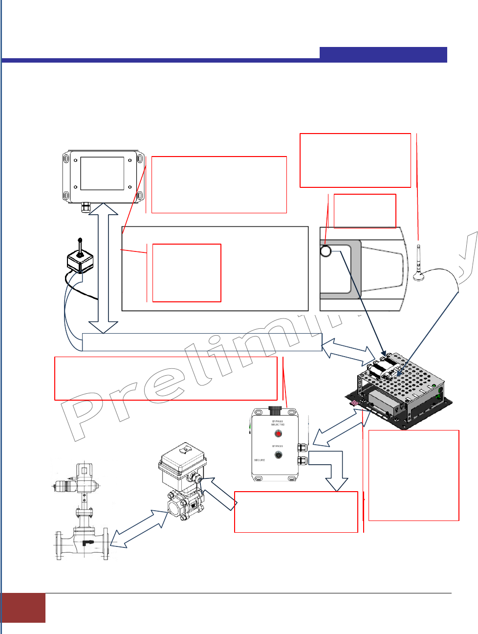
Figure 6.- Installation Guidelines
GPS
ANTENNA
INTERCONNECTION HARNESS TO THE GOPOD MODULE
INSTALL THE STI
GOPOD UNDER
THE DASH IN THE
CAB, OR ON THE
PASSENGER SIDE
FIREWALL, OR BE-
HIND THE SEAT.
INSTALL THE ST-542 TOUCH
SCREEN DISPLAY ON THE
BACK OF THE TRUCK WITHIN
35 FEET OF THE GOPOD.
INSTALL THE
GO POD
RADIO
ANTENNA
MOUNT THE RAVEN
X ANTENNA ON
EITHER OF THE CAB
SIDE MIRRORS
INSTALL THE SECURE BY-PASS CONTROLLER ON
ANY FLAT CONVENIENT LOCATION,THAT IS WITHIN
30 FEET OF THE FUEL DISPENSER ON THE TRUCK.
WIRING TO BATTERY (+)
(-) VOLTAGE DETECTOR
AUTOMATED BALL VALVE
AUTOMATED
BALL VALVE
TO PRODUCT
PUMP
Contents –STIB 22637 Rev. A
| Installation Guidelines| Section 2
9
Mobile GoPOD System Wiring Configuration
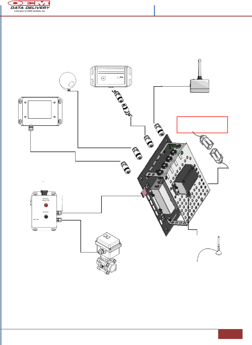
Figure 7.- Mobile GoPOD System Harness Installation
GOPOD RADIO ANTENNA
ST-511
2’ MOLDED
HARNESS
STOB-100 SECURE
BY-PASS CONTROLLER
WITH E-STOP
GPS ANTENNA
ST-560-200
HMI DISPLAY
AUTOMATED
BALL VALVE
30’ MAX
HARNESS
LENGTH
35’ MAX
LENGTH
(SUPPLIED)
SERVICE TRACKER/
PUMP TRACKER
RS-232 CONNECTION
30’ MAX
LENGTH
(SUPPLIED)
BATTERY CABLE
(5) AMP SUPPLY
(SUPPLIED)
+12VDC
SYSTEM
POWER
WIRING,
(SUPPLIED )
30’ MAX
HARNESS
LENGTH
WIFI ANTENNA
AND WIRING
30’ MAX
LENGTH
(SUPPLIED)
Contents –STIB 22637 Rev. A
10
Section 2 | | Confidential and Proprietary, Property of OEM Data Delivery a Division of OEM
Controls, Inc|
The GoPOD Electrical Connections
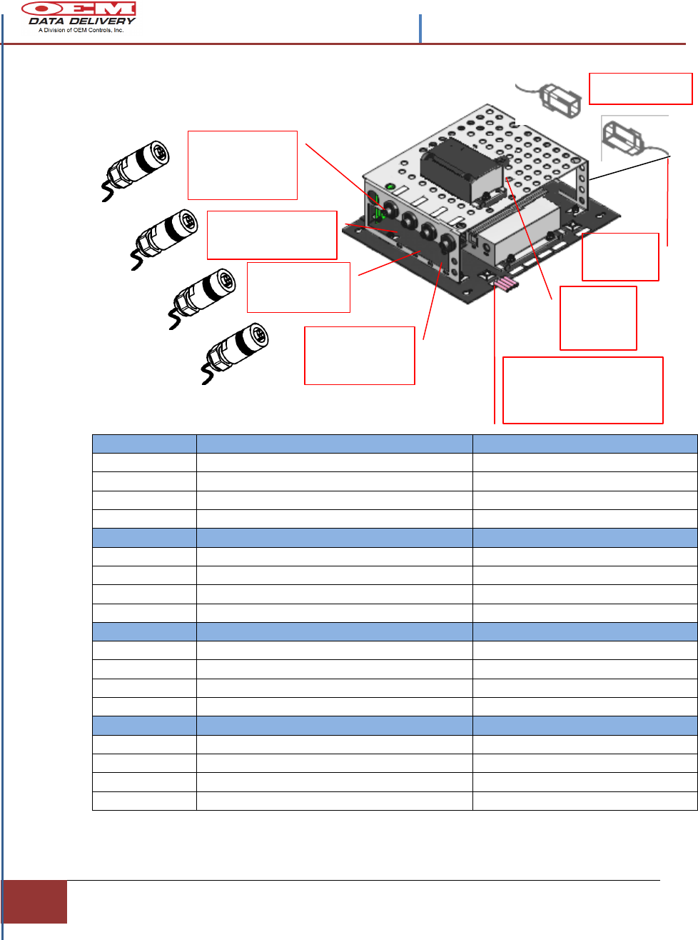
Figure 8.- The GoPOD Electrical Installation
ST-511-200
SIGNAL NAME -RADIO ANTENNA
COM1 AT GOPOD
RED
+12VDC
1
BLUE
TO RX1
2
WHITE
FROM TXD
3
BLACK
-12VDC
4
STI CPU
SIGNAL NAME –RS-232 WITH I/O
COM 2 AT GOPOD
RED
+12VDC
1
J2-33
RS 232 TXO
2
J2-22
RS 232 RXO
3
BLACK
-12VDC
4
ST-560-200
SIGNAL NAME – GPS ANTENNA
COM3 AT GOPOD
BROWN
+12VDC
1
BLUE
TO GPS RX1
2
WHITE
FROM GPS TXD
3
BLACK
-12VDC
4
ST-542Q
HMI DISPLAY
COM4 AT GOPOD
BROWN
+12VDC
1
BLUE
RS232 TXO
2
WHITE
RS232 RXO
3
BLACK
-12VDC
4
ST-511-200
GoPOD Radio
Antenna
RS-232 Interface
with ST11-CPU
ST-560-200
GPS Antenna
ST-542-200
HMI Display
Secure Pump Option
splice connectors.
See figure 13.
COM 1
COM 2
COM 3
COM 4
Modem
/WIFI
Antenna
+12VDC
Power
Battery cable
Contents –STIB 22637 Rev. A
| Installation Guidelines| Section 2
11
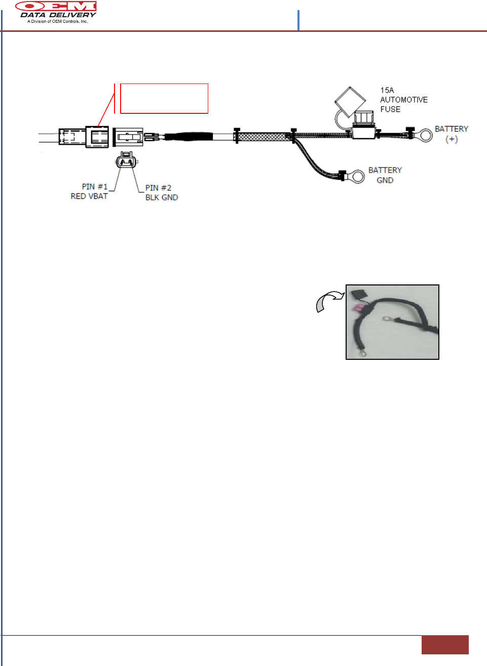
The Battery Cable for GoPOD
1. Connect the battery harness ring terminal “RED” wire to the battery
positive 12VDC or 24VDC post.
2. Connect the battery harness ring terminal “BLACK” wire to the ground
source on the battery.
3. Run the battery cable back to the GoPOD
enclosure and connect it to the power connector
installed on the perforated cover.
4. Put a 15 Amp Fuse in the fuse holder and close
the cap. A (Green) LED should be visible on the GoPOD CPU
Figure 9.- Battery Cable Connection Instructions
Power Supply Requirements
Typical Supply Voltage: 8-15 VDC
The OCI Modules can withstand the following conditions without any
permanent damage;
Reverse Polarity: The V-Bat and Ground terminals can be
INTERCHANGED
Short Circuit: Any Input or Output from the system can be shorted to
V-Bat or Ground.
GoPOD Power
Connector
Contents –STIB 22637 Rev. A
12
Section 2 | | Confidential and Proprietary, Property of OEM Data Delivery a Division of OEM
Controls, Inc|
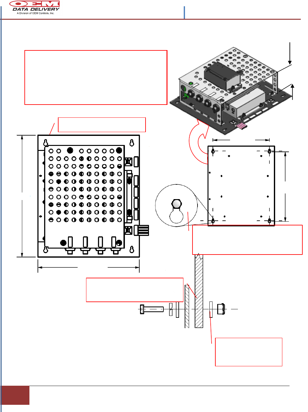
Installing the GoPOD CPU
Figure 10.- Installing the GoPOD Assembly
Note: For proper ventilation of system heat, the
GoPOD module must be mounted in a place
where it’s perforated cover is open to air
movement.
Recommend: Bulkhead mounting that will
support at least 15 LBS.
8.50
10.50
10.0
12.0
Slide the Mounting Plate’s keyholes
onto the pre-existing mounting
hardware and tighten bolts
Bulkhead, Flat
washer and ¼-20
Nut.
Mounting Plate, Flat washer,
Lock washer, and ¼-20 Bolt.
Mount with this End Up
3.58
Secure the GoPOD module as shown using the
mounting plate’s pre-drilled keyholes as a template to
position the mounting hardware properly.
Contents –STIB 22637 Rev. A
| Installation Guidelines| Section 2
13
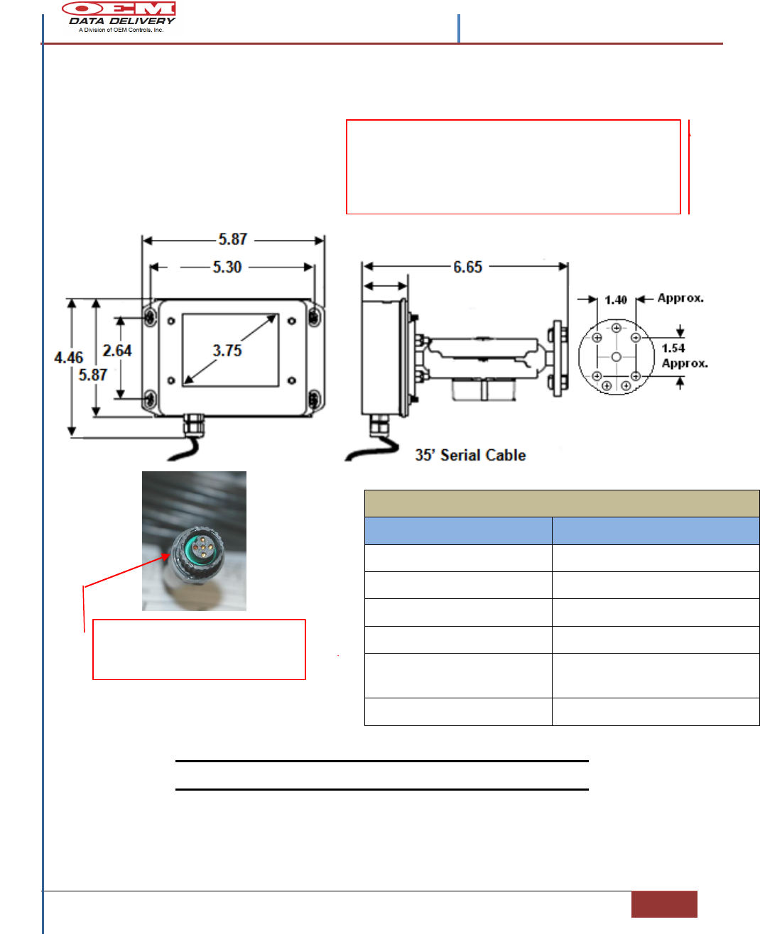
ST-542 Outline Dimensions and Interface
Connectors
Figure 11.- ST-542 Outline and Dimensions
Note: All dimensions are in inches.
ST-542-200 MECHANICAL SPECIFICATIONS
ITEM
DESCRIPTION
MATERIAL
ZINC IP67
MOUNTING HARDWARE
8-32 X LG (RECOMMENDED)
VIEWING ANGLE
H: 140°, V: 120°
DISPLAY TYPE
QVGA TFT LCD
ENVIRONMENTAL
TEMPERATURE
-40°C +70°C
OPERATING VOLTAGE
8 VDC to 24 VDC
ALIGN MATING CONNECTOR
KEYWAYS, BEFORE STARTING TO
MATE CONNECTORS.
Mounting
Plate
Dimensions
Mount the ST-542 with four (4) 8-32 Pan Head
or Round Head screws to a flat surface,
usually on the back of a fuel truck with easy
access for the equipment operator, using the
mounting holes provided.
Contents –STIB 22637 Rev. A
14
Section 2 | | Confidential and Proprietary, Property of OEM Data Delivery a Division of OEM
Controls, Inc|
Mounting the ST-542 (HMI)
Before starting:
Record the ST-542 SERIAL NUMBER, located on the side of the HMI and
the MACHINE NUMBER that you are installing the equipment on, for
reference purposes. This information must be reported back to OEM Data
Delivery for tracking purposes.
1. Turn off the engine and the master switch.
2. Visualize how to run the wires from the battery box and the engine to the
GoPOD CPU.
3. Mount the ST-542 on a flat surface convenient to the operator’s reach and
visibility.
4. If the ST-542 is mounted outside the vehicle, drill a hole (3) three inches below
the ST-542, and 1/2inch in diameter.
5. Pull the pigtail harness through this hole and route the cable to the GoPOD
CPU. This will protect the harness from the elements and road hazards.
6. Plug the connector (J1) from the pigtail on the ST-542 and push the cable
through the 1/2 inch drilled hole.
7. Secure the harness using cable-ties, leaving adequate slack in the wires.
Mobile radios and high power AC equipment or transmission lines are
potential sources of interference. If interference is a problem a shielded
cable which is connected to chassis ground is advised. Contact OEM
Controls for further assistance.
Installing the ST-542 harness: Be aware of moving parts, provide
adequate slack for wires around moving parts. Do not have unsecured or
hanging wires.
When mounting the ST-542 (HMI), beware of compartments that open;
Example: Where a radiator assembly lifts up, as in a bob cat or other skid
steers. Choosing a secure location will prevent damaging the ST-542.
Before drilling check for obstructions and sensitive equipment (e.g.
radiators, hydraulic tanks, fuse boxes etc.).
Recommended: Plug the drilled hole with a recognized
caulking compound (such as RTV) after routing the ST-542
harness through the opening.
Contents –STIB 22637 Rev. A
| Installation Guidelines| Section 2
15
Installing the GPS Antenna
Mount the Garmin GPS antenna on the roof, or highest flat non-operating surface
of the equipment. Be sure the antenna is in a horizontal position, with an
unobstructed view to the atmosphere.
Electrical Wiring Termination for GPS Antenna
Figure 12.- GPS Antenna Installation Instructions
GPS ANTENNA 30’ HARNESS
SIGNAL NAME
GOPOD (M1) P-19779
RED
+12VDC
COM4 -1
GREEN
TO GPS RX1
COM4 -2
WHITE
FROM GPS TXD
COM4 -3
BLACK
-12VDC
COM4 -4
NOTE: Align keyways of
mating connectors before
securing contacts
Contents –STIB 22637 Rev. A
16
Section 2 | | Confidential and Proprietary, Property of OEM Data Delivery a Division of OEM
Controls, Inc|
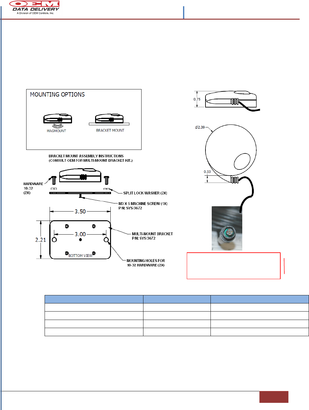
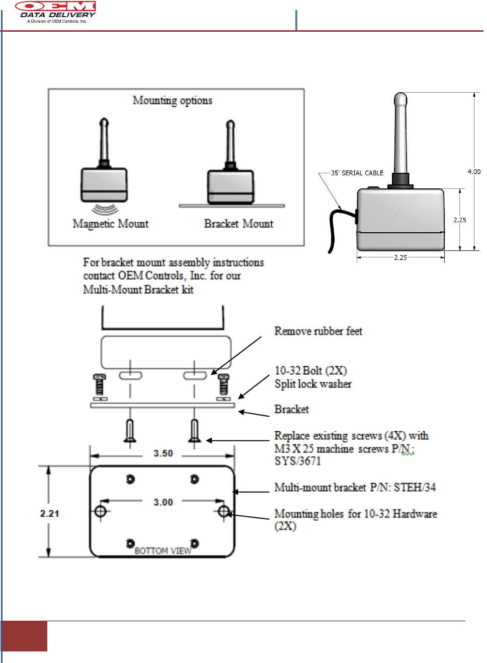
The Radio Antenna Installation Guidelines
Figure 13.- GoPOD Radio Antenna ST-511 Installation Instructions
Contents –STIB 22637 Rev. A
| Installation Guidelines| Section 2
17
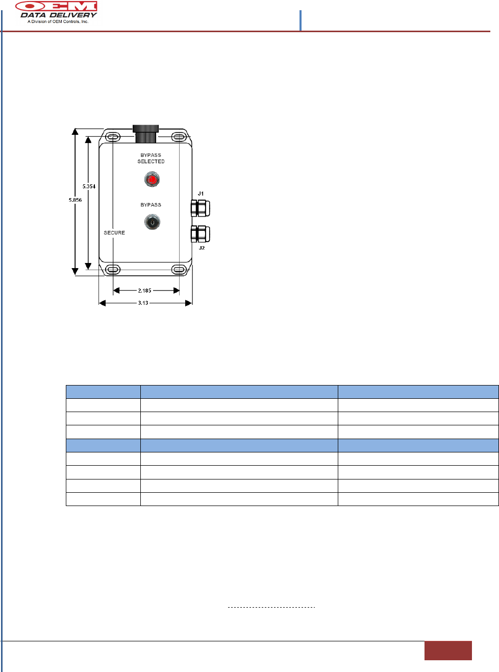
Installing the Secure By-Pass Controller
Turn off the engine and the master switch.
Figure 14.- Secure Fueling Controller STOB-100 Installation Instructions
For technical problems with the installation, contact OEM Data Delivery, and our
support team will respond with advice and support.
10 Controls Drive, Shelton CT 06484
203.929.8431 www.oemdd.com
J1
SIGNAL NAME
BALL VALVE ACTUATOR
BLACK
HOT
1
WHITE
NEUTRAL
2
GROUND
GROUND
3
J2
GOPOD ASSEMBLY SPLICES
WHITE
+12VDC
1-WHITE WIRE SPLICE
GREEN
DIGITAL INPUT
2-GREEN WIRE SPLICE
RED
DIGITAL OUTPUT
3-RED WIRE SPLICE
BLACK
GROUND
4-BLACK WIRE SPLICE
1. Visualize how to run the wires from the battery box
and the engine to the GoPOD CPU. (See figure 8.- for
the suggested wiring scheme.)
2. Mount the Secure By-Pass Controller on a flat surface
convenient to the operator’s reach and visibility.
3. If the By-Pass Controller is mounted outside the
vehicle, drill a hole (3) three inches below the
Controller, and 15/16 inch in diameter.
4. Pull the pigtail harnesses through this hole and route
the bottom cable (J2) to the GoPOD CPU assembly
and the top (J1) to the Ball Valve Actuator. This will
protect the harnesses from the elements and road
hazards.
5. Recommended: Plug the drilled hole with a recognized caulking compound (such
as RTV) after routing the (2) harnesses through the opening.
6. Secure each harness using cable ties, leaving adequate slack in the wires.
18
Section 3 | | Confidential and Proprietary, Property of OEM Data Delivery a Division of OEM
Controls, Inc|
Section 3
Testing and Troubleshooting
HMI (ST-582) Troubleshooting
Once the installation is complete, either stationary or mobile, and the GoPOD
CPU has power, the ST-542 (HMI) screen should have the entry screen visible
with commands for the
operator.
If the system is configured as a
secure system then a log-on
screen will be visible, if it is
non-secure then a
Miscellaneous entry screen will
be visible. If after the system is
powered and the (HMI)
remains blank, then a few
possible causes need to be
checked:
1. Check the HMI connection to the GoPOD assembly at COM 4, making sure
the connector has been seated correctly and fastened securely. (See Figure 9. -
for installation references)
2. Check for broken or crimped wires in the 35’ interconnection harness to the
GoPOD CPU.
3. Ensure that software as shipped is correct, check for version number and
contact OEM Data Delivery, Inc. for support.
4. Using a voltmeter check for full voltage (+12VDC) to the input side of the
CoPOD CPU. The HMI is powered from the GoPOD.
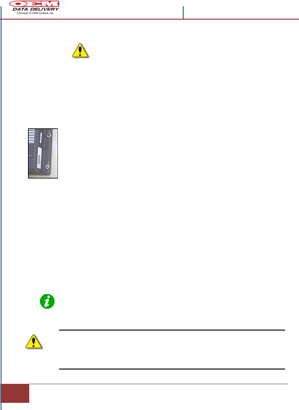
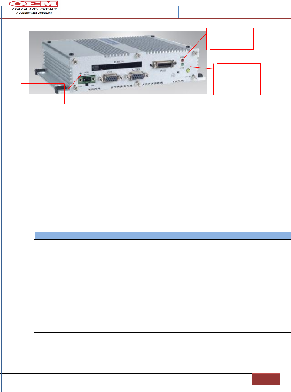
Quick Check – For the STI GoPOD CPU
The GoPOD CPU is shown without the GoPOD shield assembly. The CPU side
shown in the photo is visible and accessible through the opening in the GoPOD
perforated cover. To see how the CPU is mounted in the GoPOD perforated
cover: See Figure 3.- in the Overview Section 1.
If a wiring problem is suspected refer to the GoPOD Wiring Installation, Section
(2) for wiring information on this unit. Refer to Figures (7) and (8).
Contents –STIB 22637 Rev. A
| Testing and Troubleshooting| Section 3
19
IF – THEN: Using ST1-CPU LEDs to Diagnose the System
IF - A (Green) LED is visible, marked PWR (See photo above for location).
THEN - Good voltage and ground connections are in place.
IF – No (Green) LED .
THEN – Look for incorrect wiring from power source or improper input voltage
source. Voltage must be at least 3VDC at the CPU power.
Also check Power Switch for ON/OFF status (See photo above for location.
IF - A flashing (Red) LED is visible marked HDD (See photo above for location).
THEN – Hard disk and compact flash disc status is updating.
IF - No (Red) LED Check for secure connections at COM 1, 2,3 and 4 on the
GoPOD perforated cover mounting plate.
Troubleshooting the Automated Ball Valve
PROBLEM
CAUSE/ CORRECTIVE ACTION
BALL VALVE STOPS
WORKING
INTERRUPTED POWER. CHECK FOR BROKEN OR LOOSE
WIRES. BLOWN FUSES OR TRIPPED BREAKER. CHECK FOR
CORRECT VOLTAGE. ACTUATOR TO VALVE MISALIGNMENT.
DAMAGED HOUSING OR MOUNTING HARDWARE. WORN,
LOOSE OR SHIFTED PARTS DUE TO SHOCK, VIBRATION, ETC.
BALL VALVE IS
OVERHEATING
LOW VOLTAGE; MEASURE LINE VOLTAGE TO INSURE THAT
ACTUATOR IS RECEIVING FULL RATED VOLTAGE.
AMBIENT TEMPERATURE IS TOO HIGH AND HEAT IS BEING
CONDUCTED THROUGH MOUNTING HARDWARE.
MOTOR STALL. CHECK FOR FOREIGN OBSTRUCTION/
INCREASED LOAD DUE TO LINE PRESSURE.
LOW TORQUE OUTPUT
LOW VOLTAGE OR CURRENT, OVERHEATING
INCORRECT OPERATION
INCORRECT DURATION CYCLE, CHECK GOPOD SOFTWARE
DISPLAY TIME, INCORRECT CAM ADJUSTMENT.
Red LED
Green LED
Power
On/Off
Switch
Power
Connector
Contents –STIB 22637 Rev. A
20
Section 3 | Confidential and Proprietary, Property of OEM Data Delivery a Division of OEM
Controls, Inc|
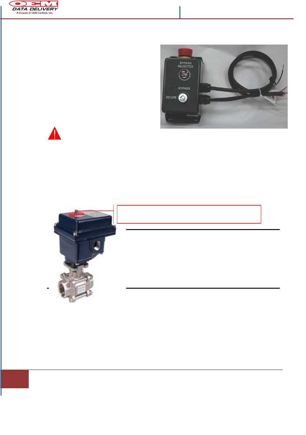
Using the Secure Fuel Controller to
Troubleshoot
Use this controller with the key
inserted and Bypass selected to check
the system without computer control.
Using the key select will directly link
the battery power to the Ball Valve
Actuator. If the Valve opens then the
GoPOD CPU or the wiring from it is
the problem.
WARNING: To perform
this test, remove any product from the system piping, and disconnect the ball
valve from the product pump.
This feature will also allow the actuator to be set if the operation of the valve is
incorrect without use of the GoPOD CPU.
This actuator can be mounted in any direction without consequence, however,
determine that the actuator, open or closed, matches the position of the equipment to
which it is mounted. Use the manual override to change the position, if necessary.
Note: Wiring power to terminals 1 & 2 will cause the
camshaft to rotate counter -clockwise. Rotating counter-
clockwise opens the valve.
Wiring power to terminals 1 & 3 will cause the
camshaft to rotate clockwise.
Rotating clockwise closes the valve.
Figure 15.- Troubleshooting the Secure Fuel Controller and Automated Ball Valve
A CRESCENT WRENCH WILL BE NEEDED TO CHANGE
THE FACTORY SETTING ON THE MANUAL OVERRIDE.

| Confidential and Proprietary, Property of OEM Data Delivery a Division of OEM Controls, Inc| |
Section 4
21
Section 4
Fueling with the HMI Touch Screen
Selecting or Entering the Equipment Number
If the equipment being serviced is not equipped with any of the
complimentary Service Trackers that communicate on command to the
GoPOD CPU, then servicing information may be entered manually via the
ST-542 (HMI) display.
This unit (ST-542) operates as an adjunct to the GoPOD CPU and servicing
information can be entered in the following manner.
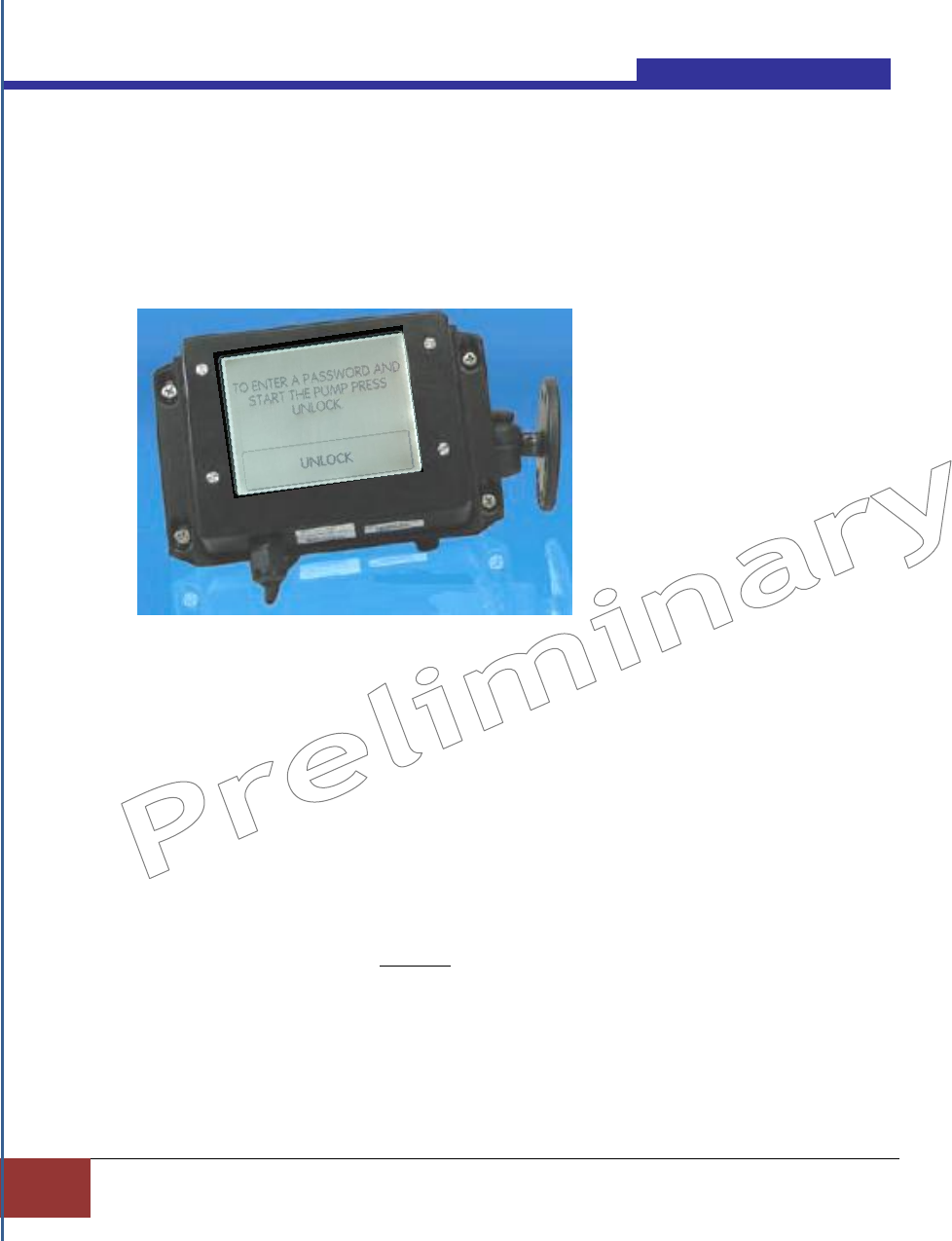
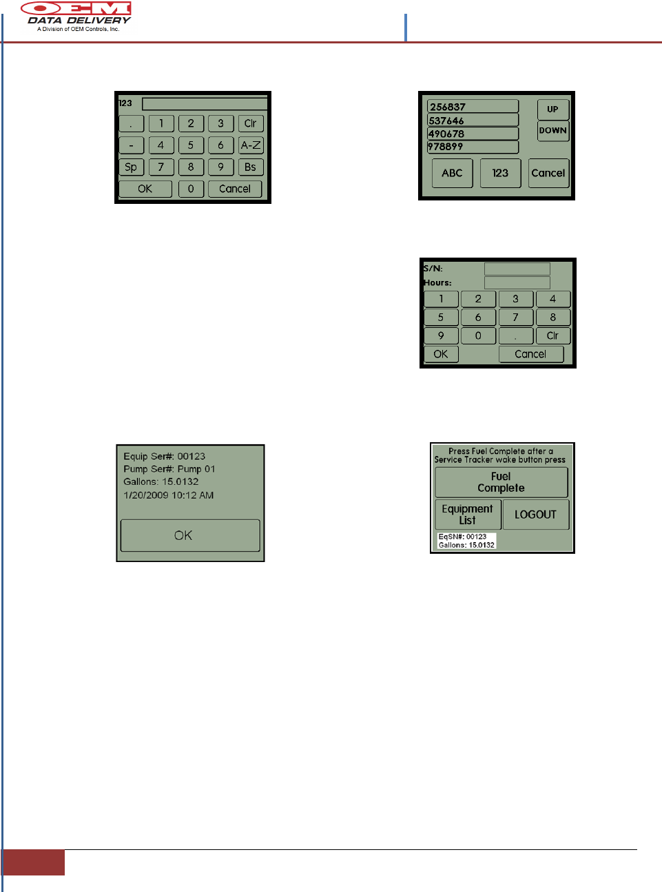
Using a Secure System Without a Service Tracker
If the system is configured as a secure
system, the user will need to enter a
password to unlock it.
When power is applied to the HMI
display, the secure Main Menu screen
will launch.
Step 1. Tap UNLOCK to enter a
password at the sign in screen.
Step 2. Enter the assigned PIN number
using the 1-2-3 screen and tap OK when
complete.
Step 3. Fuel the equipment.
Once the password is accepted the
Fueling screen will launch with the
Equipment List selection box.
Contents –STIB 22637 Rev. A
22
Section 4 |Using the HMI|
When the product is successfully dispensed, tap the Equipment List Box.
Step 4. Enter the Equipment Number using the 123 keypad on the display and tap
OK, or if previously entered select the Equipment Number from the list by tapping on
it.
The Equipment Number will be automatically
entered into the S/N field.
Step 5. Enter the Cumulative Machine Hours
(CMH) in the Hours field (optional) and tap OK.
Equipment Number and servicing data will
be displayed. This real time data will be requested by GoPOD and transferred via the
GoPOD radio antenna RT-511, to the home base as a permanent record of this
transaction.
Entering Data in a Secure System With a Service Tracker
Start with Steps 1. and 2. To unlock the GoPOD, Then fuel the equipment piece.
Step 6. When the
Summary screen
launches tap OK
Tap OK
The final part to the transaction will display the Equip/SN and the amount of
product pumped at the bottom of the screen. When transaction is complete, tap
LOGOUT. If there is no input to the HMI screen within (5) minutes the system
will timeout and return to the UNLOCK screen.
Contents –STIB 22637 Rev. A
| Confidential and Proprietary, Property of OEM Data Delivery a Division of OEM Controls, Inc||
Section 4
23
When the product is successfully dispensed the Equipment Number and
servicing data will be displayed. This real time data will be requested by
GoPOD and transferred via the GoPOD radio antenna RT-511, to Mobile
mounted GoPOD. This data will be downloaded via the WIFI connectivity to
the home base as a permanent record of this transaction. It is then formatted,
downloaded into a web report each night. Information easily integrates with
any major back office management system and with dedicated ports on the
CPU, for communication, there is never an interruption of equipment
operation.
The operator is now free to select a new Equipment Number.
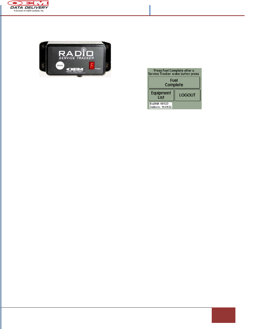
Figure 16.- Using the HMI to Fuel
Press and hold the “WAKE” button on the
Service Tracker until the F appears in the
POWER window.
Tap “Fuel Complete” when the product is
dispensed. The Equip/SN and gallons
pumped will display at the bottom of the
screen.
Contents –STIB 22637 Rev. A
24
Section 4 |Using the HMI|
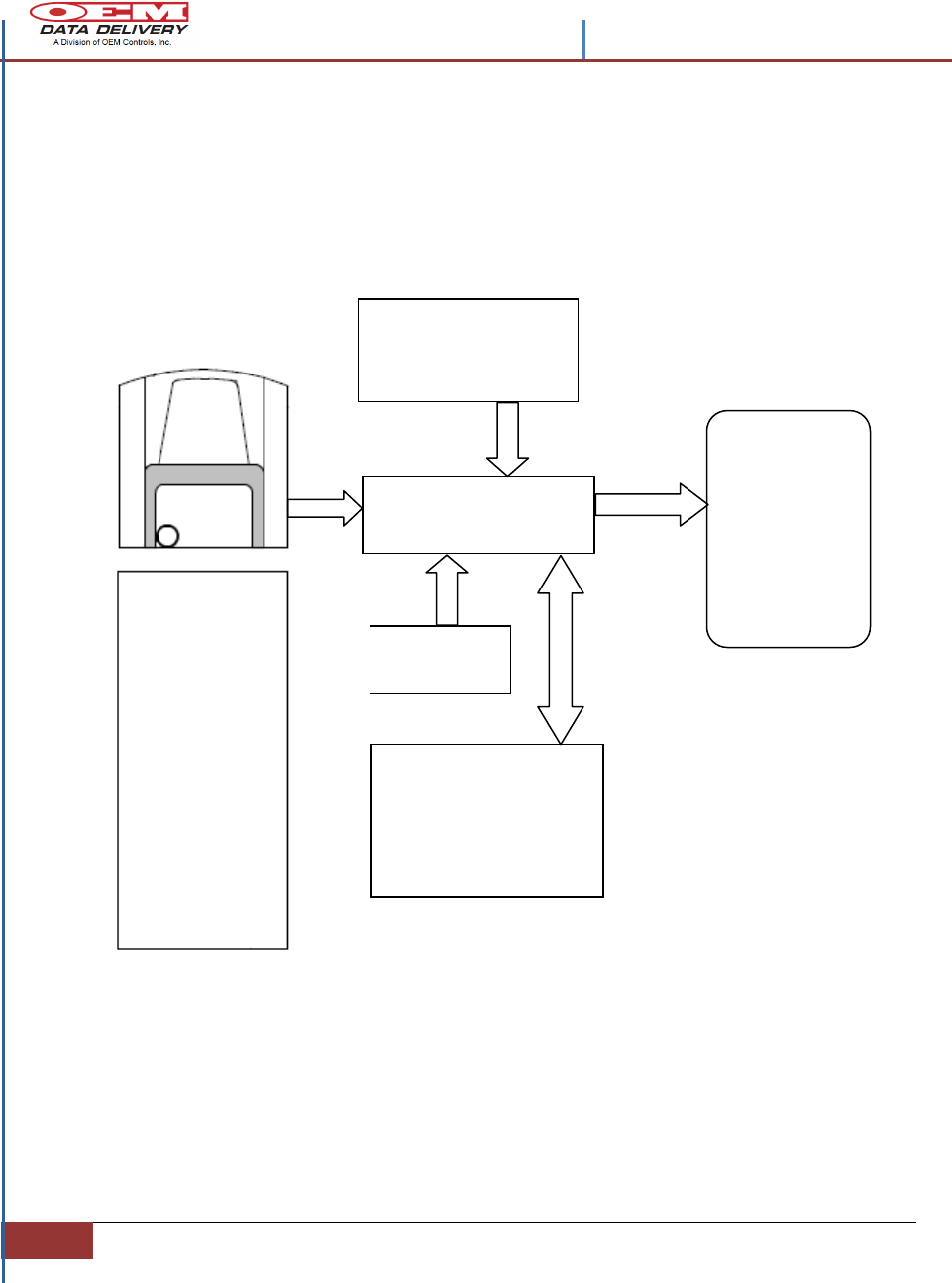
Mobile GoPOD Secure Fueling System
Block Diagram
Figure 17.- Mobile GoPOD Secure Fueling System Block Diagram
GPS ANTENNA
INTERNET ANTENNA
GOPOD RADIO
ANTENNA
ST11 GoPOD
CPU Assembly
Auxiliary Service
Tracker Modules
ST-550
ST-900
ST570
Pump Tracker
SECURE BY-
PASS
CONTROLLER
AUTOMATED
BALL VALVE
PRODUCT
PUMP
ST-542 HMI
Interface

| Confidential and Proprietary, Property of OEM Data Delivery a Division of OEM Controls, Inc| |
Section 5
25
Section 5
Index
A
Automated Ball Valve, 6
B
Battery cable, 12
C
Cumulative Machine Hours, 8
E
Electrical wiring scheme, 11
Entering data, 23
Equipment numbers, 25
G
GoPOD mechanical specifications, 13
GoPOD Radio antenna mechanical installation, 18
GPS Mechanical Installation, 17
I
Installation Guidelines, 10
O
Overview of the the Serial Pump Tracker, 1
R
Radio Pump Tracker, 8
Reverse polarity, 13
S
Secure Fuel By-Pass Controller, 4
Serial Pump antennas, 7
Short Circuit, 13
ST-542 (HMI), 3
ST-550 Service Tracker, 8
ST-900 Service Tracker, 8
STI-GoPOD, 3
STI-GoPOD technical specifications, 4
Supply Voltage, 13
T
Troubleshooting, 20
U
Unlocking (HMI), 24
W
WIFI, 4